-
This invention relates to mobile telephony, and in particular to systems for
use on board vehicles.
-
There has been considerable activity in recent years in proposals to allow the
use of mobile telephones in environments where conventional cellular telephony base
stations cannot provide coverage, in particular on board ships and aircraft. These
vehicles frequently travel beyond the range of land-based cellular base stations,
which typically have a range of the order of 1 to 10km.
-
There are also circumstances when temporary provision of cellular telephone
facilities is required at a remote location where such facilities are not normally
available, or are temporarily unavailable, for example when the fixed infrastructure
has been damaged by a natural disaster.
-
There are a number of special difficulties to be addressed if a standard
cellular telephone is to be used in an aircraft. Firstly, many cellular base stations have
antennas arranged for maximum gain in the horizontal plane, so an airborne cellular
telephone may not be able to obtain a signal from any base station, even when flying
over land served by a cellular base station network. If the range of the base stations
does extend to the normal flying height of aircraft, frequency re-use patterns, which
allow several base stations to use the same radio frequencies without interference,
are designed on the assumption that a mobile unit served by one base station is not
able to exchange radio signals with other base stations using the same frequency.
This assumption ceases to be valid if a mobile unit is several thousand metres above
the ground, since it may be in line-of-sight of a large number of base stations
simultaneously. Moreover, although reliable handover of a mobile unit can be
achieved from moving vehicles travelling at speeds of up to 200km/h, a typical
passenger aircraft travels at speeds approaching 1000 km/h. Airlines also impose
restrictions on the use of powerful radio signals on board, as a precaution against
possible interference with the aircraft's electronic systems.
-
For truly global coverage, satellite telephones are available. However, these
are expensive and much heavier than a cellular telephone. Both cellular telephones
and satellite telephones also suffer from the screening effect of being inside a metal
hulled vehicle. As with cellular telephones, the unrestricted use of a portable satellite
telephone within an aircraft may be prohibited.
-
A user without his own satellite telephone may use special facilities provided
on board, such as the service provided to several airlines by the applicant company
under the Registered Trade Mark "Skyphone". This uses onboard terminals
connected, through a satellite link between the aircraft and a satellite ground station,
to the telephone network. Another system, TFTS (terrestrial flight telephony system,
marketed as "Jetphone"), operates in a similar manner, but uses a direct link between
the aircraft and the ground station, without a satellite link. Similar systems are
provided on board ships. However payment for these services is generally at the
point of use (or prepaid), and may be in a foreign currency. Calls made to the user's
cellular telephone will not be successful unless the calls can be diverted to the
telephone number of the onboard user terminal (which will generally not be known to
the caller), and any special facilities offered by the user's cellular network will in
general be unavailable. A user with his own cellular telephone account which,
through "roaming" agreements between network operators, can be used in many
different countries, would therefore prefer to continue to use his cellular telephone
subscription when travelling within or between these countries on board an aircraft or
other vehicle.
-
Proposals have been made, for example EP0915577 (Rohde & Schwartz) for
a facility which would allow cellular telephones to make outgoing calls by way of the
aircraft's own onboard telephone system. This allows the aircraft's onboard systems
to impose power control on the mobile units and ensure that their radio transmissions
are kept within safe limits. However, the cellular telephone is not directly connected
to the cellular network, so conventional cellular radio location update processes
cannot be used to inform the user's home network of its current location and allow
incoming calls to be routed to the telephone.
-
Proposals have also been made to allow a user to use his own cellular radio
identity when using the satellite facility, instead of a special identity under the
satellite system. This would allow billing to be made through the user's normal
cellular radio account, and would also allow incoming calls made to his cellular
telephone number to be received whilst travelling. To this end, systems have been
developed which allow call diversions to be set up to allow calls made to the user's
cellular number to be transferred to a destination node of the tracking radio system.
The destination node may be an onboard handset temporarily allocated the user's
cellular identity, or it may be an onboard base station capable of wireless connection
to the user's own cellular telephone. Systems of this general kind have been
disclosed in International Patent Applications WO99/12227 (Nokia), WO94/28684
(Nordictel) and WO98/26521 (Ericsson); European Patent Applications 0920147
(Alcatel) and 0915577 (Rohde & Schwartz), and United Kingdom Patent Application
2310973 (Motorola). An onboard base station can be integrated with other onboard
systems, allowing local control of the base station's transmitter, and those of the
mobile units with which it is co-operating, so as to keep their power within permitted
limits.
-
This is made possible by an invention disclosed in the International
application filed on the same date as the present application, with applicant's
reference A25823 and priority date 14
th September 1999, which provides apparatus
for enabling a termination point of a first telecommunications system to initiate call
diversion instructions in the switching system of a second telecommunications
system such that calls initially directed to a telephone apparatus usable with the
second telecommunications system are diverted to the said termination point in the
first telecommunications system, the apparatus comprising means in the first
telecommunications system for identifying the telephone apparatus from which calls
are to be diverted and the termination point to which calls are to be diverted, and an
interface means between the first telecommunications system and the switching
system of the second telecommunications system, the interface means comprising:
- means to indicate to the switching system that the telephone apparatus is in a
specified operating condition, irrespective of the true operating condition of the
telephone apparatus,
- and means to generate an instruction to the switching system to divert calls,
intended for the telephone apparatus, to the said termination point of the fist
telecommunications system when the telephone apparatus is indicated as being in
the said predetermined operating condition.
-
-
In the preferred arrangement the first and second telecommunications systems
are a satellite telephone system and a cellular telephone system respectively, the
identification information being a user identity associated with the telephone
apparatus, and the network address of the termination point.
-
Other aspects of the invention disclosed in the aforementioned International
patent application provide the novel features of each of the individual
telecommunications systems which co-operate to form the complete system, and
methods of operation of these individual co-operating systems and of the complete
process.
-
A second arrangement, disclosed in the applicant's International Patent
Application having the same filing date as the present application and the applicant's
case reference A25937, claiming the priority date 25th August 1999, has apparatus
for providing telephone connection between one or more cellular radio telephones and
a fixed cellular radio switching system, comprising a moveable cellular system on
board a vehicle, a fixed cellular radio switching system, and a tracking radio link
providing radio connection between the moveable cellular switching system and the
fixed cellular switching system, the moveable cellular system comprising a moveable
telephone switching system connected to one or more base transceiver stations for
providing radio connection with the cellular radio telephones, and having means for
initiating a control call over the tracking radio link to the fixed cellular radio switching
system in response to the detection of the presence of a cellular radio telephone in
the area of coverage of base transceiver stations, and the fixed cellular radio
switching system having registration means responsive to such control calls to
indicate to other switching systems that calls to a cellular radio telephone currently
served by the moveable switching system should be initially directed to the fixed
cellular radio switching system, the fixed cellular radio switching system also having
call diversion means responsive to such control calls to allow incoming calls directed
to the cellular radio telephone to be diverted to the moveable cellular switching
system by way of the tracking radio link. In the embodiment described in that
application, the movable system has means for generating an association between a
destination node of the tracking radio link and an identity code of a cellular radio
telephone, and means for storing the said associated identities in stores associated
with the fixed and moveable cellular switching systems, thereby allowing both
cellular radio switching systems to translate between the cellular radio identity and
the node identity. The apparatus is arranged such that calls directed to a cellular
telephone currently co-operating with the moveable switching cellular system are
diverted by the fixed cellular switching system to a node of the tracking radio system
having the identity associated with the cellular radio identity, the node having means
for connecting the call to the moveable cellular switching system and the moveable
switching system having means for retrieving the cellular network identity associated
with the node and routing the call to the cellular telephone having that identity.
-
In the cellular telephone systems described in the aforementioned International
Patent applications the interface units are arranged to appear to the switching system
as a typical radio base station control system, to which the mobile handset is
currently working, although in fact no radio base stations are actually controlled by it.
This interface unit may therefore be considered to be a "Virtual" Base Site Controller.
The switching system itself requires no modification: it merely registers that the user
is working to the "Virtual" Base Site Controller and stores the user details in its
"Visitor Location Register" (VLR), in the same way as it would for a mobile unit
working to any real base site controller to which it is connected. The interface unit
also generates a call diversion instruction, which will appear to the switching system
to have come from the mobile handset, by way of the "Virtual" Base Site Controller.
This call diversion instruction is set up in the switching system such that if the
"Virtual" Base Site Controller responds to a call request directed to the mobile unit
with a "busy line" response (or some other specified condition), calls are to be
diverted, through normal network interconnects, to a specified directory number,
namely that of the satellite termination point to which the user is connected. The
interface unit does not in fact monitor the real condition of the user terminal, (which
is not operatively connected to the interface unit), but instead always returns the
"line busy" signal to the switching system.
-
The interface unit includes a store to record any diversion settings existing for
the telephone apparatus prior to the diversion to the second network being set up.
This allows these settings to be retrieved when the user disconnects from the first
telecommunications system, so that they can be reinstated in the switching system
of the second telecommunications system, or transferred to another
telecommunications system, when the telephone apparatus makes contact with a real
radio base station, thereby initiating a handover procedure from the "Virtual" Base
Site Controller to the real one.
-
Should a second call attempt to the user's cellular telephone be made whilst a
call is in progress to the onboard system, the switching system may be arranged to
divert it to another predetermined number, such as the user's "voicemail", or
automatic answering service, address.
-
If the user termination is in an aircraft or other vehicle connected to a ground
station (by satellite or otherwise), it may move from the area covered by one satellite
(or ground station) to that of another. In that case, the network address of the
termination changes. To accommodate this, the interface may be provided with
means to store the address of termination points in the first system, means to record
changes to the said addresses transmitted to it from the first system, and means to
modify the diversion instruction in the switching system when such a change takes
place. Alternatively, the termination point may be arranged simply to repeat the setup
process, causing the mobile unit to be re-registered with the interface unit, (which
will not be apparent to the switching system, as it will perceive the same "virtual"
base site controller), and to transmit a new call divert instruction to the revised
address of the termination point.
-
The inventions disclosed in the aforementioned International patent
applications allow the diversion of PSTN-compatible speech calls to the user's current
location in the first telecommunications network. However, modem cellular telephone
systems have other capabilities, in particular the data system known in the GSM
standard as "Short Message Service" (SMS). In the cellular network data messages
are carried over a separate data network and cannot be diverted to a different
directory number, such as that of the user's current satellite terminal, or the satellite
address currently associated with the user's terminal, in the same way as voice calls
because the PSTN cannot handle them. Moreover, with regard to arrangements in
which the call is routed to a standard satellite telephone terminal as provided in
aircraft, such terminals are not equipped to receive such messages.
-
A first aspect of the present invention provides a method of converting data
messages originally formatted for transmission over a first telecommunications
network for generation of a display on a display unit of a first type, such that
messages can be transmitted over another telecommunications network for display
by a selected display unit of a second type forming part of a server-based information
display system, wherein the address information in the original data message is
replaced by address information appropriate to the selected display unit to generate
an amended data message, and a new data message is created, addressed to the
server of the information display system and having the amended data message as
payload, and wherein the server converts the amended data message into control
instructions suitable to display the information content of the data message on the
information display unit identified in the amended data message.
-
A second aspect provides apparatus for converting data messages originally
formatted for transmission over a first telecommunications network for generation of
a display on a display unit of a first type, such that messages can be transmitted over
another telecommunications network for display by a selected display unit of a
second type forming part of a server-based information display system, comprising
means for replacing the address information in the original data message by
address information appropriate to the selected display unit to generate an amended
data message, and
means for creating a new data message addressed to the server of the
information display system and having the amended data message as payload.
-
A third aspect provides server apparatus forming part of a server-based
information display system for receiving messages generated by the apparatus
defined above, for display by a selected display unit, the server comprising means for
converting a data message formatted for display on a display unit of a first type into
control instructions suitable to display the information content of the data message
on an information display unit of a second type controlled by the server, the
information display unit being identified in the data message
-
In the described embodiment the data message is originally formatted for
transmission over a cellular telephone network for display by a cellular telephone
handset. The data message may be generated by the cellular switching system in
response to a message being deposited in a call answering system.
-
In one arrangement, prior to transmission of the amended original data
message to the server an alerting data message is created, indicative of the presence
of the original data message, addressed to the server of the information display
system, and carrying address information appropriate to the selected display unit,
thereby causing the server to generate control instructions suitable to display an
alerting message on the information display unit so identified, and wherein the
amended original data message is forwarded to the server in response to an
instruction from a termination point associated with the destination display unit. This
ensures that data messages are only transmitted when the user has accepted them,
thus allowing the network operator to charge the user for the service.
-
The amended data message may also include password data, the server being
arranged such that when it receives a data message it causes the display means to
indicate the presence of a data message, and displays the data message only if it
receives a predetermined input from a user terminal associated with the display
means.
-
Embodiments of the invention. will now be described with reference to the
Figures, in which:
- Figure 1 is a schematic diagram showing the functional relationships
between the systems which co-operate to form one embodiment of the invention
- Figure 2 is a more detailed schematic diagram of the network termination
and associated card reading equipment, which for illustrative purposes will be
assumed to be on board an aircraft
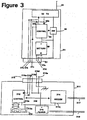
- Figure 3 is a diagram showing part of an alternative arrangement of network
termination, arranged for co-operation with a cellular telephone handset
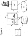
- Figure 4 is a schematic diagram showing the functional relationships
between the components of the fixed part of the first telecommunications system
which co-operate in the invention,
- Figure 5 is a schematic diagram of the switching system, interface unit, and
associated parts of the second telecommunications system;
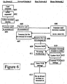
- Figure 6 is a flow chart showing the process by which a diversion is set up in
the second network to a termination connected to the first network
- Figure 7 is a flow chart showing the process by which a call coming in to the
second network is connected to a telephone connected to the first network
- Figure 8 is a flow chart showing the process by which the second network
restores the original settings for a telephone when it disconnects from the first
network.
- Figure 9 illustrates the forwarding process implemented to a data message.
- Figure 10 illustrates a conditional forwarding process for a data message.
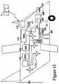
- Figures 11 and 12 show the general arrangement of the various components
which co-operate in a further embodiment of the invention: Figure 11 shows the
moveable vehicle-borne parts and Figure 12 the fixed, ground based, parts.
- Figures 13 and 14 show the method of operation of this embodiment
- Figure 15 is a flow chart showing a call diversion process, for use when the
system has to be temporarily shut down.
-
-
The following embodiments illustrate the invention using a standard switched
cellular network, using the terminology of the "GSM" standard for illustrative
purposes. However, the invention is applicable to other cellular networks, including
packet networks, which are used to carry data over a distributed computer network
such as the "Internet", carrying messages using formats such as the "Internet
Protocol" (IP). Thus, unless the context clearly demands otherwise, any reference in
this specification to switching includes the equivalent routing functions in a packet
network of this kind.
-
Figure 1 shows the general arrangement of the various components which
co-operate in this embodiment. Note that traffic links (which can carry speech, data,
etc) are shown as full lines, signalling links used only for call set up are shown as
broken lines.
-
The onboard part 2 (shown in more detail in Figure 2) comprises one or more
handsets 25 (which, in the alternative arrangement of Figure 3, are the users' own
cellular telephone handsets 31), connected to a termination point 20 of the satellite
network. The termination point 20 is in communication with a ground station 4,
shown in more detail in Figure 4. In this embodiment, the communication link is made
through an earth-orbiting satellite 6.
-
The principal components of the ground station 4 relevant to this invention
are an antenna 44 which communicates, by way of the satellite 6, with the onboard
system 2, an Access Control and Signalling Equipment (ACSE) 40 which carries out
call switching functions to allow calls to be placed through the public switched
telephone network (PSTN) 8 to other telephones 85, and a Card Management System
42 which authorises the use of an individual terminal 25 according to user identities
entered with respect to that terminal. There is also a register 43 of card identities, to
provide a correspondence between the user identities used by the satellite terminal
and the corresponding cellular telephone user identities (not necessary if the cellular
telephone identity is read directly by the terminal 20, as will be described with
reference to Figure 3), and to provide billing information.
-
The card management system 42 interacts with an interface unit 52 of a
"host" cellular telephone network 5, shown in more detail in Figure 5. This network 5
is connected to the public switched telephone network (PSTN) 8 and to other cellular
networks 7 through a switching centre 50. Associated with the interface unit 52
there is an "aircraft location register" 41 which monitors the terminals currently
served by each individual satellite, and modifies the functioning of the interface unit
52 when a terminal 20, for example on board an aircraft 2, moves from the coverage
area of one satellite 6 (and its ground station 44) to another
-
The cellular network 7 illustrates in simplified form the system architecture of
a "GSM"-standard cellular radio system, and the terminology used in this standard.
The network 7 has a switching system (MSC) 70 to allow connection of one or more
base transceiver sites (BTS) 74, through one or more base site control systems 72,
to the PSTN 8 and thus to other telephones 85. A mobile telephone 75 may establish
radio contact with one of the base stations 74 in order to make and receive
telephone calls. The network 7 also includes a "Visitor Location Register" 71, which
maintains details of those cellular telephones 75 currently co-operating with the
network 7. Mobile telephones according to the "GSM" standard are capable of co-operating
with different networks ("roaming" between networks). To allow this to
take place, when a mobile telephone 75 changes from one network to another, the
network to which it has moved retrieves data from a "Home Location Register" 73
permanently associated with the handset 75. The network 7 in which the Home
Location Register 73 associated with a given handset is to be found is identifiable
from the handset's identity code. The Home Location Register also records the
identity of the network 7 with which the mobile handset 75 is currently operating.
-
The "host" network 5 operates like conventional cellular network, but is
provided with an interface unit 52, which interacts with the mobile switching centre
50 as a base site controller would. This interface unit 52 may be in addition to one or
more base site controllers (not shown). The interface unit does not interact with any
base transceiver sites or mobile handsets, but obtains user details (in particular the
identity or a mobile handset) from the card management system 42 to allow it to
appear to the switching centre 50, and the HLR 73 in the user's home network, that
it is in radio communication with a mobile handset 25. It can then control the call
forwarding instructions stored in the host network's VLR 51, to cause incoming calls
directed to that handset to be diverted, through the switching system 40 of the
satellite network 4, to the satellite terminal 20.
-
Figures 2, 3 and 4 illustrate a first embodiment of the invention, applied to a
satellite telephone system such as that provided by the applicant company under the
Registered Trade Mark "Skyphone". Figure 2 shows a first embodiment of the mobile
part which has a standard card reader, whilst Figure 3 shows an alternative
arrangement which allows a user to use his cellular telephone handset. Figure 4
shows the ground station.
-
The onboard system 20 shown in Figure 2 comprises a plurality of user
terminals 21, 21a (only one shown in detail), connected by a multiplex and radio
interface unit 28 to an antenna 29 which provides radio communication with a
satellite 6. Each user terminal 21 has a card reading unit 23 into which an intending
user can insert a card 24 or other data carrier providing user identification data. The
data may give details of the user's credit card account, or a special account for the
use of the onboard telephone service. The card reader 23 may be adapted to read the
SIM (Subscriber Identity Module) of a GSM-standard cellular telephone. (It should be
noted that one variant of the method according to the invention does not make use
of the card reading apparatus 23,24,26, although it may nevertheless be present for
use by other customers of the satellite system).
-
Further user terminals 21a may be set aside for non-voice applications, for
example an onboard facsimile machine.
-
The user handset 25 provides the usual keypad, microphone and earphone to
allow the user to make telephone calls. The user handset 25 and the card reader 23
are both connected to a processor 26 which converts data read from the card 24,
and keystrokes input from the handset 25, into data signals for transmission over the
radio link 29. It also provides identification data indicative of which of the terminals
21 it is. A further processor 27 performs analogue/digital conversion of speech
signals from the handset 25.
-
The digitised signals from each terminal 21 are multiplexed and modulated
onto a radio carrier in a interface unit 28, and transmitted from the antenna 29.
-
The antenna 29 also receives signals which are demodulated and
demultiplexed in the unit 28. Data signals are processed in the processor 26, whilst
digitised speech is converted to analogue speech in the analogue/digital converter 27
and fed to the handset 25.
-
The interface unit 28 also includes a connection to the data bus 22 of the
aircraft 2 giving access to aircraft parameters such as undercarriage deployment,
"weight-on-wheels", time to destination, altitude, etc. When a predetermined
condition indicative of the impending end of a flight is met, the interface unit 28
transmits a signal to the ground station to cause a deregistration signal to be
transmitted to the card management system 42.
-
Because the onboard telephone system was originally designed for making
outgoing calls, the handsets 25 provided in existing terminals 21 are not equipped
with a suitable call alerting device. The handsets 25 could be modified to provide a
buzzer or light to alert the user to an incoming call. Alternatively, to avoid distracting
other passengers on the aircraft, the telephone terminal 21 may be connected to an
at-seat entertainment system 200, to provide an alert either through the earpieces
202 or on the screen 201.
-
Instead of the terminals 25, an altemative arrangement may be used as
shown in Figure 3. In this arrangement each onboard terminal 25 is replaced by an
onboard interface device 311 to which a user's own mobile radio telephone 31 can
be connected electrically, thereby allowing the mobile telephone to be used without
using its radio antenna. It is a modification of the system described in the applicant
company's International Patent Application WO97/36442, published on 2nd October
1997, to which the reader is referred for further details. In this modified version a
GSM (Global System for Mobile communication) mobile telephone 31 comprises r.f.
transceiver circuitry 32 coupled to an antenna 33, base band signal processing and
control circuitry 34, a rechargeable battery pack 35, a switch 36 and a socket 37.
The processing and control circuitry 34 has a data output terminal 34a coupled to
both the r.f. transceiver circuitry 32 and a first contact 37a of the socket 37. A data
input terminal 34b of the processing and control circuitry 34 is coupled to the r.f.
circuitry 32 and a second contact 37b of the socket 37. A third contact 37c of the
socket 37 is coupled to a control input of the processing and control circuitry 34.
Fourth and fifth contacts 37d, 37e of the socket 37, which are respectively for 0V
and +V power supply lines, power the telephone 31, and may also be arranged to
recharge its batteries 35. The +V terminal of the battery pack 35 is also connected
to the processing and control circuitry 34 and to an input terminal of the switch 36.
The output terminal of the switch 36 is coupled to a +V input terminal of the r.f.
circuitry 32. A control terminal of the switch 36 is coupled to an output of the
processing and control circuitry 34.
-
The interface unit 311 comprises a control circuit 312, a user input unit
313, including a keypad and a display, a V.24 33.6 kbit/s modem 314, a power
supply unit 315 and a plug 316. The plug 316 has five contacts 316a-316e which
correspond to contacts 37a-7e of the socket 37 of the mobile telephone 31. The
first contact 316a of the plug 316 is coupled to a data input terminal of the control
circuit 312 and the second contact 316b of the plug 316 is coupled to a data output
terminal of the control circuit 312. A bi-directional serial link 318 is provided
between the control circuit 312 and the modem 314 for modem control and data
signals. The third contact 316c and fifth contact 316e of the plug 316 are coupled
to the +V output of the power supply unit 315. The fourth contact 316d of the plug
316 is coupled to the interface unit's 0V supply wiring. The user input unit 313 is
coupled to the control circuit 312 for the input of user commands and the output of
display control signals from the control unit 312 to the user input unit 313. The +V
output of the power supply unit 315 is also coupled to + V input terminals 312a,
313a, 314a of the control circuit 312, the user input unit 313 and the modem 314.
The modem 314 is coupled to a telephone line 317 and the power supply unit 315 is
arranged to receive power from an electricity supply 319.
-
When the user wishes to connect to the interface unit 311, he connects the
plug 316 of the interface unit 311 to the socket 37 on his telephone 31 by a cable
(not shown). The voltage on the third contact 37c of the socket 37 is detected by
the processing and control circuitry 34 which thereby determines that the telephone
31 has been connected to the interface unit 311. The connection of the battery 35
to the power supply 315 by way of the connections 37d/316d and 37e/316e also
allows the battery to be recharged.
-
Once the processing and control circuitry 34 has determined that the
telephone 31 has been connected to the interface unit 311, it sends a control signal
to the switch 36, causing it to open, isolating the r.f. circuitry 32 from the battery
pack 35 and the power supply 315 in the interface unit 311. The processing and
control circuitry 34 also responds to the voltage on the third contact 37c of the
socket 37 by selecting alternative control programs or constant data to allow for
delays in the signal path from the telephone 31 to the controller 30 which are caused
by the use of the satellite link 6 and the modems 314, 32.
-
In this arrangement, instead of the need for a separate card reader 23, the
telephone 31 identifies itself to the telephone network 40/42 by generating its
terminal identity code (IMSI in the case of a GSM telephone). The registration signal
is not transmitted from the antenna 3 because the r.f. circuitry 32 is disabled.
Instead, it is output to the interface unit 311 via the first contacts 37a, 316a of the
socket 37 and plug 316
-
The operation of this onboard system will now be described with reference
to Figure 6. When the card reader 23 or interface unit 311 detects the presence of a
card 24 or handset 31 respectively, (step 601) it generates a prompt to indicate to
the user that he may wish to have calls diverted to the onboard system. If the user
requires this service, he enters a code on the keypad of the handset 25, 31 which
causes a divert request to be generated (step 602). The details from the card 23 (or
SIM of the handset 31) are then passed to the processor 26 which also provides the
identity of the terminal 21 (step 603) and transmits the data to the interface unit 28.
-
Alternatively, these steps (602, 603) may be activated by the user without a
card, by dialling an access code (divert request 602) followed by further keystrokes
to identify the account to be used (terminal identity step 603). These keystrokes may
include the user's MSISDN (which, as his own directory number would be known to
him). To prevent misuse of the system by unauthorised personnel, a security code
(Personal Identification Number: "PIN") may be added. This code may have been
issued previously to the user, or the user may request such a code by making a call
using the satellite system to his home network's customer service department and
providing personal details to the operator to prove his identity.
-
The user may select for the identity of a terminal 21a other than his own at
seat terminal 21 to be selected as the destination for incoming calls. For example, if
his MSISDN code (or one of them) relates to a facsimile machine having cellular
capability, he may request that incoming calls to that number be directed to an
onboard facsimile machine 21a.
-
The data received by the interface unit 28 is then transmitted to the ground
station 4 (step 604). The further steps (605-615) in the process are carried out by
the co-operating networks 4, 5 and will be described later.
-
If the user decides that he no longer Wishes to have his calls diverted to the
terminal 21, he may cancel the diversion instruction by entering a special code on the
keypad of the handset 25, 31. Disconnect codes may also be generated in the
interface unit 28 for all the termination points 21, either by the cabin crew or
automatically in response to a signal detected on the aircraft's data bus 22 which is
indicative of the imminent end of the journey, such as undercarriage deployment,
weight on wheels, low altitude, or time remaining to destination as determined by the
aircraft's flight management system. The disconnect instruction is transmitted (step
801, Figure 8) by way of the switching system 40 in the ground station 4, to the
interface unit 52 whose operation (steps 802 to 805) will be described later.
-
The Ground Station 4 shown in Figure 4 has a radio antenna system 44 for
communicating with the terminal 20, through a satellite link 6 or otherwise. Signals
are handled by an Access Control Signalling Equipment (ACSE) 40 which carries out
switching functions to route calls to or from the public switched telephone network
(PSTN) 8.
-
A card management system 42 comprises a data acquisition unit 47 which
reads data transmitted from the card reader 24, and/or keyed in by the user, to
identify the type of user, confirm the user's account details and arrange billing for
any calls made, through a billing system 45 which raises invoices, or interacts with
the systems of a credit card operator or bank.
-
In the existing onboard systems a user cannot receive calls, unless the caller
knows the unique "AES" number of the handset 21, 21a. This is unlikely, as the
number depends on the identity of the aircraft, the seat, and the serving satellite or
base station.
-
The equipment just described is augmented in the present embodiment by
an interface 46 with the host network 5, and through that to the Home Location
Register 73 of each network 7 (Figure 1) whose subscribers are to be given access to
the service, which stores a concordance between the card identities and the card-holder's
cellular radio telephone number (MSISDN: mobile systems integrated services
data network number), on request from the data acquisition unit 47, which is
arranged to recognise the card identities which require such translation. In a preferred
embodiment the concordance is supplied to a register 43 in the ground station by the
operator of user's home network 7, when the network operator provides the user
with the card. The operator of the home network 7 also records the concordance in
its own Home Location Register 73. This arrangement allows the existing card
readers 23 to be used on board the aircraft, without modification. If the users' mobile
subscriber identities are supplied from the onboard system, either by reading the
identity (reader 311) or by the user keying it in, the store 43 can be used for
verification, or omitted. Billing information is also returned to the user's home
network 7.
-
The operation of the ground station 4 will now be described with reference
to Figure 6. The data acquisition unit 47 receives the card details from the reader 23
(see steps 601 to 604 already discussed) and if it identifies as those details as
corresponding to a cellular user (step 605), it retrieves the cellular user identity from
the store 43 containing this concordance, or from the HLR 73 of the user's home
network, (step 606). (This step can be omitted if the user's mobile network identity
is provided by the onboard apparatus 20).
-
The data transmission unit 46 then generates a signal for transmission of the
cellular user identity, together with the identity of the terminal 21, to the cellular
network 5 acting as host to the interface (step 607). This host network 5 will, in
general, not be the same as the user's home network 7. The further steps (608 to
615) in this process will be described later, with reference to Figure 5.
-
If a cancellation signal is received from the aircraft in respect of a given
terminal 21, (step 801, previously discussed) the data transmission unit 46 transmits
a "cancellation" signal to the host network 5. As already discussed, the cancellation
signal may be generated either for an individual handset 21, by its user dialling a
special code, or for all handsets as the result signals received by the radio interface
unit 28 over the aircraft's data bus 22 indicative of the imminent end of the flight.
-
An embodiment of the host network 5 of the invention is shown in Figure 5.
Its operation will be discussed with reference to Figures 6, 7 and 8 in this network 5
an interface unit 52 is provided, which is arranged to appear to the switching system
50 as if it is a normal base station of the cellular radio system.
-
In order to do this, the interface unit 52 is provided with a data acquisition
unit 54 which receives from the card management system 42 of the ground station 4
the identity of the cellular telephone it is to represent, and the AES identity of the
onboard terminal 20 (step 608, Figure 6). Mobile telephones have three identification
codes: the equipment identity (IMEI, which will not be discussed further here), the
directory number (MSISDN) and the actual SIM identity (IMSI). In practice, for
security reasons, the IMSI is not made generally known, and a user is normally
identified by his MSISDN unless the SIM itself is used. If the SIM is used in the card
reader 23, or the user's telephone is used in the arrangement of Figure 3, (in which
case no concordance is required) the IMSI can be read directly from the data received
by the data acquisition unit 54. However, if the user keys in his own identification
data (step 603), or a concordance is provided by the card reader 23, the data
acquisition unit will receive the MSISDN, and not the IMSI. (There may also be a PIN
or other security code, which is checked by the data acquisition unit 54).
-
In the GSM standard it is possible to obtain an IMSI if the MSISDN is known
by interrogating the appropriate Home Location Register 73. To do this, the interface
unit 52 transmits a "request for routing information" signal, using the MSISDN (step
609). The standard HLR 73 responds to such a request with a signal which includes
the IMSI corresponding to the MSISDN in the request (step 610).
-
(The "request for routing information" signal was provided under the GSM
standard as a means of obtaining routing information for data messages intended for
a destination for which only the MSISDN number is known. However, it may be used
for other purposes, such as that described above).
-
The telephone identity (IMSI), whether obtained directly from the card reader
23 or handset 31, or indirectly as just described, is passed to a network registration
unit 55 which exchanges signals with the mobile switching centre 50 in the same
way that a real cellular telephone would do. The mobile switching centre therefore
informs the user's Home Location Register 73 that the mobile telephone is now
registered with the network 5 (step 611). The Home Location Register 73 records
that the mobile handset is now registered with host MSC 50 (step 612).
-
It should be noted that, although registered with the host MSC 50, the user's
mobile handset is not operatively connected to the host MSC 50 - in fact the mobile
handset may be switched off to allow the card 24 to be used, or it may be connected
to a user terminal 311. The user may be in an aircraft, anywhere in the world within
the coverage area of the satellite network.
-
The user's details, including any diversion instructions, are sent by the Home
Location Register 73 to the network's VLR 51 (step 613). A store 57 records a copy
of the details of these diversion instructions (step 614).
-
Conventionally, any incoming calls for a mobile user are sent in the first
instance to the user's home network 7, and the HLR 73 provides information to
identify the MSC 50 where the mobile handset can currently be found. Consequently,
in the present arrangement, any incoming calls intended for the mobile user will now
be directed to the network 5, as the mobile user is currently registered there.
-
The data acquisition unit 54 in the interface 52 now passes the directory
number of the termination point 21 to a call diversion instruction unit 56, which
generates a "divert on busy" instruction to the VLR 51 (step 615). This is a standard
divert arrangement, and operates such that should the mobile unit appear to be
engaged on another call when a call attempt is made to it, the call attempt is diverted
to a specified directory number, in this case the termination point 21 or 21a,
identified by its AES code. This diversion instruction replaces any previous instruction
held in the VLR 51. Further settings may be made in the call diversion instruction unit
56, such as the identification of a termination point 21 to which a data message is to
be sent when a call is diverted to another termination point 21 a.
-
Of course, there is in fact no mobile telephone connected to the interface
unit 52, and therefore it is unable to connect incoming calls to the mobile telephone
in the conventional way, or to identify the current true operating condition (switched
off, busy, ready for calls, etc) of the mobile handset. Instead, the system responds to
a call attempt as will now be described with reference to Figure 7.
-
When a call attempt is made (step 701), the home MSC 70 to which the call
is initially routed obtains from the HLR 73 the current location of the mobile
telephone (step 702), and on receiving the identity of the host MSC 50 (step 703),
directs the call there (step 703). The host MSC 50 in turn transmits the call attempt
to the currently serving base station, which is in fact the interface unit 52 (step 704).
If the disconnect procedure (to be described later with reference to Figure 8) has
been carried out - the call will not be connected to the onboard system (step 705),
and instead a signal is transmitted back to the home MSC 70. Otherwise, call
attempts received by the interface unit 52 are handled by a call request handling unit
58, which automatically returns a "busy" signal to any such request (step 706). The
MSC 50, on receiving the "busy" signal, retrieves the diversion information from the
VLR 51 (step 708) allowing it to route the call through the PSTN 8 to the user
terminal 21, 21a (step 710).
-
In the event that the destination terminal 21a is not the terminal 21 that
originated the instruction, the call request handling unit 58 of the ground-based
interface unit 52 may be arranged such that whenever a message addressed to the
user's MSISDN is diverted to the terminal 21a, the call request handling unit 58 also
generates a data message (step 711) for transmission to the instructing terminal 21
by way of the MSC 50, PSTN 8, and satellite system 4, 6 (step 712) either during
the call or after it ends. Such a message can be used for example to alert the user of
the terminal 21 that a facsimile message addressed to him has been sent to the
terminal 21a. As with the call alerting process described above, the message may be
displayed using the in flight entertainment system 200.
-
If a second call attempt is made, the ACSE 40 may identify that the divert
instruction will not work as it is currently handling a diverted call to that number. The
default condition in such cases is to arrange for the second call to be diverted to the
user's voicemail address (not shown) in his home network 7. The user may also be
sent a data message to inform him of the new voicemail message. This message
would normally be sent to the mobile unit, which appears to the MSC 50 to be co-operating
with the interface unit 52, so the MSC 50 transmits the data message to
the interface unit 52 (step 711). In order to inform the user of the new voice mail
message, the interface unit 52 now regenerates the data message for forwarding to
the user terminal 21 via the MSC 50, PSTN 8, and satellite system 4, 6 (step 712)
either during the call or after it ends. However, data messages are not suitable for
switching via the MSC 50 and PSTN 8, nor for handling by the on-board terminal 21
as it is only equipped for voice. Because the IMSI is recorded in the HLR 73 as being
registered with the "Virtual" BSC, or interface unit, 52, any other data messages
intended for the user will also be routed to the interface unit 52, and require
forwarding to the user. The way this is achieved, according to the invention, will be
discussed later, with reference to Figures 9 and 10. As with the call alerting process
described above, the message may be displayed using the in flight entertainment
system 200.
-
Generally, the detection of the same IMSI from two sources causes an HLR
to disconnect both callers as a fraud prevention measure. Since this system causes
the generation of an IMSI from the interface unit 52, instead of directly from the
mobile telephone to which that IMSI relates, the user's mobile telephone should be
switched off, or connected to an onboard interface device 311 which disconnects
the radio circuits, to prevent the network detecting the IMSI in two places, which
would disrupt the call routing processes in the HLR 73 and elsewhere.. If the user is
on board an aircraft, he should not be using his mobile handset in the conventional
manner, and so there should be no problem. However, if the user, having left the
aircraft, switches on his telephone 75 before the network 5 has reported a loss of
the mobile unit from its own network, the mobile unit may be perceived by the HLR
73 as being registered with two networks at once. To avoid this possibility, a
disconnection procedure is followed as described with reference to Figure 8.
-
As already discussed, to stop calls being diverted to the user termination
point 21, and restore the original call diversion settings, a disconnection signal may
be transmitted from the onboard system 28 to the host network's interface unit 52
(step 801). The disconnection signal may be activated by a special code entered by
the user, or it may be generated automatically by data collected from the aircraft's
data bus 22 indicative of the imminent end of the flight. Note that this disconnection
signal merely controls the interface 52 - it has no effect on calls in progress, which
is routed from the host MSC 50 by way of the PSTN 8.
-
The disconnect instruction is received by the interface unit 52 (step 802) and
causes the call diversion instruction unit 56 to retrieve the call diversion data stored
in the store 57 (step 803) and generate a call diversion instruction restoring the
original settings to the VLR 51 (step 804). This ensures no further calls are routed to
the onboard terminal 21.
-
The interface unit 52 next causes the network registration unit 55 in the
interface unit 5 to instruct the MSC 50 that the user is no longer connected to the
network 5 (step 805). This allows the mobile unit to register with another network 7
in the normal way. Call attempts to the user number will continue to be routed by the
Home HLR 73 to the MSC 50 with which the mobile unit was most recently
registered, (i.e. the host MSC 50) but as that MSC cannot now find the mobile unit,
any such incoming call will return a "not found" signal to the home MSC 70 which
will divert the call according to any diversion instructions set up, or fail the call.
Alternatively, the host MSC 50 may handle the diversion itself if the mobile unit is
"not found", using the original diversion instructions now in the VLR 51, having been
retrieved from the store 57 (step 804 above).
-
Having left the aircraft, the user may switch on his mobile telephone 75,
which will register with the local network (e.g.7) and will retrieve the original divert
information from the HLR 73 (note that in general the HLR 73 will not be in the same
network), and will cause all data relating to the user to be deleted from the VLR 51 in
the "host" network 5.
-
An alternative embodiment, in which voice calls are handled by a user's
cellular handset but data calls and call alerts are still handled by the onboard in-flight
entertainment system, is depicted in Figures 11 and 12.
-
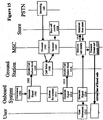
The system can be categorised into two main components: namely the
onboard part 101 (Figure 11) and the fixed part 102 (Figure 12), which communicate
with each other through a satellite connection 6. The onboard part (Figure 11)
comprises a moveable cellular system 111,112,114,116 and the onboard part 113 of
the tracking radio system. The fixed part 102 (Figure 12) is itself in two parts,
namely a satellite ground station 4, which is similar to that shown in Figure 1, and
the fixed "host" cellular network 104, which is a public land mobile network (PLMN)
104, in turn interconnected with other PLMNs 70 and conventional wired networks
(PSTN) 8 to allow calls to be made between users of different networks.
-
As shown in Figure 11, the system provides a cellular radio subscriber with
the ability to use his own handset 110 aboard an aircraft, located anywhere within
an agreed satellite coverage area. The coverage on board the aircraft can be
provided by any suitable means, using known radio repeater distribution systems 111
to provide radio coverage wherever required.
-
The distribution system 111 is fed by a base transceiver site 112, served by
a base site controller 114 and a mobile switching centre 116, which may have its
own visitor location register 117, for onward transmission to the satellite ground
station 4 via a satellite tracking system 113. The satellite tracking system may be a
conventional satellite telephone system as commonly used for ship-to-shore
communications, and for the airborne systems previously referred to, providing a
satellite link 6 from the aircraft or ship's satellite tracking system 113 to the satellite
ground station 4. The satellite ground station 4 is in turn connected to the mobile
switching centre (MSC) 141 of a conventional cellular telephone system, referred to
hereinafter as the "host" system 104 and shown in Figure 12.
-
The satellite link 4 - 6 - 113 is therefore between the onboard MSC 116 and
an MSC 141 (the "host" MSC) of the land-fixed "host" network 104. The user
record in the home location register (HLR) 73 of the user's home network identifies
the mobile unit 110 as currently served by the land-based network 104, and routes
the call to the host MSC 141, which will in turn recognise from its entry in the land
based VLR 144 that this mobile unit is currently being served by the onboard MSC
116. The way this is arranged will be described later.
-
This arrangement allows integration of the onboard MSC 116 with the
onboard switching capability associated with the conventional satellite telephone
system and the aircraft's internal communications system 115. In particular it
provides a simple means of providing passengers and crew with a "Wireless PBX"
facility, as users on board the aircraft can communicate with each other through the
BSC 114 without using the satellite link 4 - 6 - 113. When a call is made by a cellular
telephone 110, the onboard MSC 116 first consults its VLR 117 to establish whether
the called party is currently served by the same MSC 116. If this is the case, it
connects the call without the use of any inter-MSC links. Thus calls made between
two users both on board the aircraft 101 may be made without the use of the
satellite link 4 - 6 - 113. The satellite connection provides several voice channels
and a signalling channel (supervisory control - management channel), and can be
made by any connection of appropriate capacity.
-
The host network 104 may support one or more further base site controllers
142 controlling conventional base transceiver sites 74. The host Mobile Switching
Centre 141 also has an associated "Visitor Location Register" 144 which, in
conventional manner, records details of the cellular telephones currently co-operating
with the Mobile Switching Centre 141, so that details can be exchanged with the
Home Location Register 73 of the user's home network for billing purposes, and to
allow incoming calls to be routed correctly. These details include the identity of the
link 4, 142 to which the user is connected, allowing different call charges to be
applied for use in different cells, and in particular to distinguish between calls made
through the onboard base transceiver site 112 and calls made through conventional
base site controllers 142.
-
In the cellular mobile network 104, standard GSM functionality is used.
Users aboard the aircraft will be able to use this service provided they are subscribers
to the host network 104, or any other network 70 which has a "roaming" agreement
with the host network 104, provided the subscriber has the roaming capability
authorised by his service provider.
-
In this embodiment of the invention, the "host" network 104 operates like a
conventional cellular network, but is provided with an interface unit 148 for
interworking with the satellite ground station 4. This interface 148 allows the
switching centre 141 to obtain user details (in particular the identity of a mobile
handset) from the satellite system 4 to allow it to appear to the network 104, and
thus to the HLR 73 in the user's home network, that the mobile handset is in radio
communication with a base station under the control of the mobile switching centre
141 when in fact it is in communication with the onboard MSC 116. The mobile
switching centre can then arrange for call forwarding instructions to be stored in the
VLR 144, to cause incoming calls directed to that handset to be diverted, through the
switching system 40 of the satellite network 4, to the onboard MSC 116.
-
The operation of the system is as follows. When a mobile unit 110 first
makes contact with the onboard cellular system 101 it transmits its identity code
(IMSI) to the onboard MSC 116 in the usual way. The onboard MSC 116 can obtain
verification data from the user's HLR 73 (identified by the IMSI code) to verify the
authenticity of the user, and permit outgoing calls. However, because the onboard
MSC 116 is only contactable through the satellite system, incoming calls to the
mobile unit 110 cannot be reliably routed to the onboard MSC 116 over a
conventional link. In order to avoid a requirement for special facilities in each network
70 it is convenient to make the mobile unit 110 appear to be working to a
conventional mobile switching centre 141.
-
When the onboard MSC 116 detects a call attempt or registration attempt
from a mobile unit 110, it collects from the mobile unit its identity code (IMSI) and
passes it to a processor 118. If the processor 118 has not previously done so, it
generates a temporary onboard identity for association with the mobile identity code
(IMSI), and stores it in a memory 119. For aircraft fitted with at-seat satellite
telephone equipment, each handset has an identity code (generally related to the
number of the passenger seat to which the handset is fitted) to allow outgoing calls
to be billed to the correct user and to allow the system to be used to communicate
between passengers. Spare numbers in this system (referred to herein as "pseudo
seat numbers" - PSN) may be used as the temporary onboard identities allocated to
mobile handsets working to the onboard MSC 116. If the mobile handset 110 has
previously contacted the onboard MSC 116, and not subsequently de-registered, the
processor 118 now retrieves the PSN corresponding to the IMSI from the memory
119.
-
As with the arrangement of Figure 1, the present embodiment allows the
host network to translate the called party's IMSI to an AES code (including seat
number), which in this case is a pseudo-seat number (PSN) allocated randomly from
the numbers left spare after codes have been allocated for at-seat terminals. The
translation takes place in the host network, without the need for the caller to know
the AES code. The temporary onboard identity code PSN associated with the called
party's IMSI is returned to the onboard MSC 116 which sets up a call over the
satellite system to the host MSC 141 of the host network 104. The satellite system
requires certain authentication data on call set up, namely the AES code and a
subscriber identity code which normally identifies an individual subscriber to the
satellite system or, if the user does not have an account with the satellite system,
credit card details or other details to allow payment to be made. In the present case
the onboard MSC 116 provides the cellular telephone's code (IMSI) as the subscriber
identity code. For security reasons, this code may be encrypted. If an outgoing call
attempt is being made, a call attempt is then made to the number dialled; otherwise a
special code, referred to herein as the non-call code ("NCC") is used.
-
If the caller has not previously been registered, but a special non-call
registration code is used, the ACSE 40 of the ground station 4 recognises it as being
an authorised free call to the host MSC 141 and routes it accordingly. Calls using this
code are permitted even if the IMSI has not previously been registered with it.
-
The host network 104 will, in general, not be the same as the users home
network 70. In the host network 104 an interface unit 148 provides certain
additional functionality to co-operate with the satellite ground station 4.
-
When a call is received by the satellite ground station 4 using the non-call
code (NCC) the ACSE 40 retrieves the data and passes it to an interface unit 148,
which retrieves the identity (IMSI) of the cellular telephone, and the PSN associated
with it. The IMSI (de-encrypted if necessary), is passed to a network registration unit
145 which exchanges signals with the host mobile switching centre 141 in the same
way that a real cellular telephone would do if registering through one of its base
stations 74. The mobile switching centre therefore informs the user's Home Location
Register 73 that the mobile telephone is now registered with the network 104. The
Home Location Register 73 records that the mobile handset is now registered with
host MSC 141.
-
It should be noted that, although registered with the host MSC 141, the
user's mobile handset is not operatively connected to the host MSC 141. The user,
and the handset, may be on a suitably equipped vehicle anywhere in the world within
the coverage area of the satellite network 6.
-
The user's details, including any diversion instructions, are next sent by the
Home Location Register 73 to the network's VLR 144. A store 147 records a copy of
the details of these diversion instructions for subsequent retrieval when the mobile
unit deregisters.
-
Conventionally, any incoming calls for a mobile user are sent in the first
instance to the user's home network 70, and the HLR 73 provides information to
identify the MSC where the mobile handset is expected to be found, which is the
host MSC 141. Consequently, in the present arrangement, any incoming calls
intended for the mobile user will now be directed to the network 104, as the mobile
user is currently registered there.
-
The interface unit 148 passes the AES code to a call diversion instruction
unit 146, which generates a "divert on busy" instruction to the VLR 144. This is a
standard divert arrangement, and operates such that should the mobile unit appear to
be already engaged on a call when a new call attempt is made to it, the new call
attempt is diverted to a specified directory number, in this case the AES code
allocated to the mobile unit. This diversion instruction replaces any previous
instruction held in the VLR 144.
-
Finally, the registration process is closed by returning an authorisation code
from the host MSC 141 to the subscriber management system 42 of the satellite
system 4, to allow the IMSI to be recognised as a valid user identification for
subsequent outgoing calls.
-
The aircraft may have an at seat information system 200 with provision for
connection of the handset 110, similar to the hands-free sets commonly provided In
cars. This allows audio signals to be transferred to the at-seat system's headset 202,
preventing disturbance to other passengers. The at-seat system may also have means
for collecting ringing tone from the handset 110, and generating a visual alert on the
display screen 201 or an audible one on the headset 202.
-
The operation of the system will now be described with reference to Figure
13. When a mobile unit 10 first makes contact with the onboard cellular system 101
it transmits its identity code (IMSI) to the onboard MSC 116 in the usual way. The
onboard MSC 116 can obtain Verification data from the user's HLR 73 (identified by
the IMSI code) to verify the authenticity of the user, and permit outgoing call.
However, because the onboard MSC 116 is only contactable through the satellite
system, incoming calls to the mobile unit 110 cannot be reliably routed to the
onboard MSC 116 over a conventional link. In order to avoid a requirement for
special facilities in each network 70 it is convenient to make the mobile unit 110
appear to be working to a conventional mobile switching centre 141.
-
When the onboard MSC 116 detects a call attempt or registration attempt
from a mobile unit 110, (step 1601) it collects from the mobile unit its identity code
(IMSI) and passes it to a processor 118. If the processor 118 has not previously done
so, it generate, a temporary onboard identity for association with the mobile identity
code (IMSI), and stores it in a memory 119 (step 1602). For aircraft fitted with at-seat
satellite telephone equipment, each handset has an identity code (generally
related to the number of the passenger seat to which the handset is fitted) to allow
outgoing calls to be billed to the correct user and to allow the system to be used to
communicate between passengers. Spare numbers in this system (referred to herein
as "pseudo seat numbers" - PSN) may be used as the temporary onboard identities
allocated to mobile handsets working to the onboard MSC 116. If the mobile handset
110 has previously contacted the onboard MSC 116, and not subsequently de-registered,
the processor 118 retrieves the PSN corresponding to the IMSI from the
memory 119 (step 1603).
-
In existing onboard systems a user cannot receive calls unless the caller
knows the unique "AES" number of the at-seat terminal 201, which is made up of
the seat code and an identity code of the aircraft (which together make up a unique
"AES" code). It is unlikely, even for a normal satellite handset, that a caller would
know the AES code, as the number depends on the identity of the aircraft, the seat,
and the serving satellite or base station. (It should be noted that the passenger list of
an aircraft is not normally released to the general public until the flight has ended, for
security reasons). The present embodiment allows the host network to translate the
called party's IMSI to an AES code, which includes a pseudo-seat number (PSN),
which is allocated randomly from the numbers left spare after codes have been
allocated for at-seat terminals. The translation takes place in the host network,
without the need for the caller to know the AES code.
-
The temporary onboard identity code PSN associated with the called party's
IMSI is returned to the onboard MSC 116 which sets up a call over the satellite
system to the host MSC 141 of the host network 104 (step 1604). For a normal
satellite call, the satellite system requires certain authentication data on call set up,
namely the AES code and a subscriber identity code which normally identifies an
individual subscriber to the satellite system or, if the user does not have an account
with the satellite system, credit card details or other details to allow payment to be
made. In the present case the onboard MSC 116 provides the cellular telephone's
code (IMSI) as the subscriber identity code. For security reasons, this code may be
encrypted. If an outgoing call attempt is being made, a call attempt is then made to
the number dialled; otherwise a special code, referred to herein as the non-call code
("NCC") is used.
-
The satellite ground station 4 shown in Figure 4 has a radio antenna system
44 for communicating with the onboard system 101, through a satellite link 6 or
otherwise. Signals are handled by an Access Control Signalling Equipment (ACSE) 40
which carries out switching functions to route calls to or from the public switched
telephone network (PSTN) 8.
-
A subscriber management system 42 in the satellite ground station
comprises a data acquisition unit 47 which reads identification data transmitted from
the aircraft (step 1605) to identify the subscriber, confirm his account details and
arrange billing for any calls made, through a billing system 45 which raises invoices,
or interacts with the systems of a credit card operator, bank, or other telephone
operator. In the present case the card management system recognises the IMSI
transmitted as the subscriber identity. Provided the IMSI has previously been
registered with the subscriber management system 42 (as will shortly be described:
step 1616) the call is authorised using the satellite system's authorisation checking
and billing system as for any call from an onboard satellite terminal, and connected to
the PSTN 8 (step 1606), billing details being passed to the home network through
the host MSC 141.
-
If the caller has not previously been registered, but a special non-call
registration code is used, the ACSE 40 recognises it as being an authorised free call
to the host MSC 141 and processes it accordingly (step 1607) by retrieving the data
and forwarding it to the interface unit 52 in the host network 5 . Calls using this
code are permitted by the subscriber management system 42 even if the IMSI has
not previously been registered with it.
-
The host network 5, 104 will, in general, not be the same as the user's
home network 70. In the host network an interface unit 148 provides certain
additional functionality to co-operate with the satellite ground station 4.
-
When a call is received from the satellite ground station 4 using the non-call
code (NCC) the ACSE 40 transmits the data to the interface unit 148 (step 1608).
The interface unit 148 then retrieves the identity (IMSI) of the cellular telephone, and
the AES identity of the onboard terminal 201 (step 1608, Figure 13). The IMSI (de-encrypted
if necessary), is passed to a network registration unit 145 which
exchanges signals with the host mobile switching centre 141 in the same way that a
real cellular telephone would do if registering through one of its base stations 74. The
mobile switching centre therefore informs the user's Home Location Register 73 that
the mobile telephone is now registered with the network 104 (step 1611). The Home
Location Register 73 records that the mobile handset is now registered with host
MSC 141 (step 1612).
-
It should be noted that, although registered with the host MSC 141, the
user's mobile handset is not operatively connected to the host MSC 141. The user,
and the handset, may be on a suitably equipped vehicle anywhere in the world within
the coverage area of the satellite network 6.
-
The user's details, including any diversion instructions, are next sent by the
Home Location Register 73 to the host network's VLR 144 (step 1613). A store 147
records a copy of the details of these diversion instructions (step 1614).
-
Conventionally, any incoming calls for a mobile user are sent in the first
instance to the user's home network 70, and the HLR 73 provides information to
identify the MSC where the mobile handset is expected to be found, which is the
host MSC 141. Consequently, in the present arrangement, any incoming calls
intended for the mobile user will now be directed to the network 104, as the mobile
user is currently registered there.
-
The interface unit 148 passes the AES code to a call diversion instruction
unit 46, which generates a "divert on busy" instruction to the VLR 144 (step 1615).
This is a standard divert arrangement, and operates such that should the mobile unit
appear to be already engaged on a call when a new call attempt is made to it, the
new call attempt is diverted to a specified directory number, in this case the AES
code allocated to the mobile unit. This diversion instruction replaces any previous
instruction held in the VLR 144.
-
Finally, the registration process is closed by returning an authorisation code
from the host MSC 141 to the subscriber management system 42 (step 1616) to
allow the IMSI to be recognised as a valid user identification for subsequent outgoing
calls.
-
Of course, although the mobile telephone 10 is recorded in the home location
register 73 and in the host's visitor location register 144 as being connected to the
host MSC 141, it is not really there and therefore the host MSC 141 is unable to
connect incoming calls to the mobile telephone in the conventional way, or to identify
the current true operating condition (switched off, busy, ready for calls, etc) of the
mobile handset 110. Instead, the system responds to a call attempt as will now be
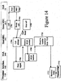
described with reference to Figure 14.
-
When a call attempt is made (step 1701), the MSC in the home network 70
to which the call is initially routed obtains from the HLR 73 the current location of the
mobile telephone (step 1702), and on receiving the identity of the host MSC 141,
directs the call there (step 1703). The host MSC 141 in turn attempts to transmit the
call attempt to the currently serving base station, which is in fact the interface unit
148 (step 1704). If the disconnect procedure already described with reference to
Figure 8) has been carried out, the call will not be connected (step 1705) and a signal
is transmitted back to the home MSC 70. Otherwise, the interface unit 148
automatically returns a "busy" signal to any such request (step 1706). Note that the
interface unit 148 has no information regarding the true operating state of the mobile
unit 110. It is merely arranged to emulate the target mobile unit's response to a call
attempt when the target mobile unit is in the "busy" condition.
-
The host MSC 141, on receiving the "busy" signal, checks whether any
incoming call currently in progress to that mobile handset has already been diverted
(step 1707). (This is a standard procedure, done to ensure that call diversions are not
attempted if they will not actually succeed). If there is no such diverted call in
progress, the host MSC 141 retrieves the diversion information (the AES) from the
VLR 144 (step 1708) allowing it to route the call through the PSTN 8 and the
satellite system 3 to the onboard system 101 (step 1710).
-
The onboard system 101 routes incoming calls to a node of the onboard
system according to the AES code. If the node is connected to a real at-seat terminal,
the call is simply routed to that terminal. However, in this case, the code corresponds
to a pseudo seat number, which the onboard satellite system switch 113 recognises
as meaning that the call is to be routed to a node connected to the onboard MSC
116. The onboard MSC 116 uses the processor 118 to retrieve from the memory
119 the cellular identity (IMSI) corresponding to the PSN, (step 1711) and then
connects the call to the mobile handset 110 having that identity in the conventional
manner (step 1712). Thus the interaction between the onboard MSC 116 and the
handset 110 is entirely conventional: ordinary handsets can be used and no initial
authorisation is required other than the standard procedures used to ensure that
international "roaming" is permitted.
-
If a second call attempt is made to a handset already in use, the ACSE 50
will identify that the divert instruction will not work as it is already handling a
diverted call to that number. The default condition in such cases is to arrange for the
second call to be diverted to the users' voicemail address (not shown) in his home
network 70. The user may also be sent a message to inform him of the new
voicemail message. This message would normally be sent to the mobile unit, which
appears to the host MSC 141 to be co-operating with the interface unit 148, so the
host MSC 141 transmits the data message to the interface unit 148 (step 1711). In
order to inform the user of the new voice mail message, the interface unit 148 now
regenerates the data message for forwarding to the onboard MSC 116 via the
satellite system 3 (step 1712) for alerting the user terminal 110 either during the call
or after it ends.
-
As the onboard system 101 is itself mobile, being on board an aircraft, call
routing to that termination may require revision from time to time. For example, the
"Inmarsat" satellite system comprises several geostationary satellites, which each
provide cover for part of the earth's surface. These areas of coverage overlap to a
large extent, but nevertheless on a long flight the aircraft may pass out of the area
covered by one satellite into that served by another. This causes a small but
significant change in the network address AES of any terminal on board the aircraft.
The aircraft location register 41 monitors the identity of all aircraft currently being
handled by the satellite ground station 4. When an aircraft moves into range of a
different satellite 6, the call diversion unit 146 responds by transmitting a new call
diversion instruction to the VLR 144. so that any further incoming call attempts are
diverted to the new network address (AES) of the node corresponding to the terminal
110. Note that the diversion store 147 is not updated.
-
Note also that this does not affect calls already in progress. There is usually
sufficient overlap in satellite coverage areas that handover from one satellite or base
station to another can be arranged to take place when no call is in progress
-
During the flight the user may decide that he no longer wishes to have his
calls diverted to the terminal 110, and switches it off. The onboard MSC 116 will
therefore fail to locate the mobile handset 110 at the next registration update. As
previously discussed, it is also desirable to disable the onboard system 101 when the
aircraft is on approach to landing, to avoid interference with aircraft systems at this
critical point in the flight (or distractions to passengers in the event of an
emergency), and also to avoid interference with base stations on the ground.
Disconnect codes may therefore be generated in the onboard MSC 116 for all the
handsets 110, either by the cabin crew or automatically in response to a signal
detected on the aircraft's data bus 22 which is indicative of the imminent end of the
journey, such as time remaining to destination (as determined by the aircraft's flight
management system), low altitude, deployment of, undercarriage, or weight on
wheels.
-
On receiving a de-registration signal (steps 801,802 Figure 8), the host
network 104 retrieves the original divert information from the store 147 (step 803)
and stores that in the VLR 144 (step 804), thereby restoring the user's own selected
divert instructions automatically.
-
Once he has left the aircraft, the user may switch on his mobile telephone
110, which will register with the local network (e.g. network 70), informing the
home location register 73 of the location update (note that in general the HLR 73 will
not be in the same network as the local network 70). The HLR 73 retrieves the user's
VLR settings from the previous host network 102. Because the original VLR data has
been restored (step 804), the temporary divert data used whilst the user was
connected to the onboard system is not fed back to the HLR. All data relating to the
user can then be deleted from the VLR 44 in the "host" network 102.
-
In use, both parties to a call, and most of the cellular network, operate
normally. The cellular telephone 110 co-operates with the base station 112 on the
aircraft as it would with any other base station 74. The home location register 73
identifies the cellular telephone 110 as currently served by the host MSC 141, and
routes incoming calls accordingly. This invention therefore allows connection to be
made to conventional handsets 110 'using standard cellular telephony equipment. The
operation of the host MSC 141 and the onboard MSC 116 are both largely
conventional except for the number translation functions carried out by the interface
units 118. 148. Using roaming capabilities, just one host MSC 141 can provide
connection to a large number of airborne MSCs 116, anywhere in the range of the
satellite system 4, 6.
-
To allow the use of the at seat display system 201 for data messages, not
suitable for transmission over the PSTN and satellite system in their original form the
interface unit 52 (Figure 5), 148 (Figure 12) is provided with a data handling
processor 53,149 for receiving data messages received over a packet data system 9
by way of the MSC 50,141 and intended for users currently associated with the
interface unit 52,148. These messages include SMS messages sent from other
callers, and SMS messages generated by the MSC 50,141 itself to alert the user that
a message has been sent to the voice mail system. The format of such a message is
shown'in Figure 9, and the process of sending and receiving it is shown in Figure 10.
-
The original message 900 basically consists of a data payload 901 and an
address 902, which is the IMSI of the destination mobile telephone (figure 9a).
-
When the interface unit 53,148 receives such a data message (step 990) it
retrieves from the data acquisition unit 54,149 the data network address of the at-seat
entertainment terminal 201 corresponding to the user's cellular identity which
was originally provided to the data acquisition unit 54,149 when the user carried out
the registration procedure (step 991). The interface unit 53,148 next generates a
data call to that address (step 992), in a form suitable for transmission by the MSC
50,141 (step 993) over the packet data network 9 to the aircraft, with an address
header corresponding to the data network address of the user's at-seat terminal
201,201. This data call may be a short message to indicate that a message is
awaiting delivery, and displaying on the screen 201 an invitation to the user to dial a
special code on his handset 25,110 to accept the message (step 994), and any
charge associated with it. This acceptance is transmitted back, by way of the MSC
50, 141 to the interface unit 53,148 (step 995). (These steps 992 - 995 may be
omitted if it is not required for users to acknowledge acceptance before receiving a
data message).
-
The interface unit 53,148 then replaces the address header (the IMSI) 902 in
the original data message with a code 912 identifying the terminal 201 and
encapsulates the message in a form suitable for transmission over the packet data
network 9 to the aircraft (step (996), with an address header 910 to send it to the
data network interface 28, 204 serving the onboard entertainment system 200, It
can thus be transmitted the interface 28, 204 over, the packet, data network 9
(step 997), effectively as a packet with an address header 910 and a payload made
up of the at-seat terminal number 912 and true payload 901 (Figure 9b).
-
On receipt of the data message, the on board data interface 28, 204 extracts
the data message payload 901, 912, (Figure 9c) (step998) and identifies the
individual at-seat terminal 201 identified by the address 912. It can then cause
display of the data message payload 901 on the screen 201 of the appropriate
terminal (step 999).
-
If password protection is required, for example to ensure that the user is
present when the message is displayed, the payload 901, 912 can also include a
password code 913, which causes the interface 28, 204 to withhold the remainder
of the payload until a predetermined sequence of keystrokes has been entered by the
user in the terminal 201.
-
In the embodiment of Figures 11 and 12 it is arranged that the MSC 141 has
similar features to those described for the MSC 50 and described with reference to
Figure 9 and 10. the invitation (step 992) is sent as a voice message to the user
terminal 110, and prompts the user to identify his at-seat terminal (in practice the
user will be asked for his seat number), either by key presses (using DTMF coding) or
by voice (step 995). The acceptance step is therefore performed over the voice
network, rather than the data network. The MSC uses this information to generate an
AES code identifying the user terminal, to be applied to the data message 910 (Figure
9). The host MSC may store this code for use with subsequent data messages,
allowing the host MSC 141 to process further data messages without requesting this
information from the user again. The request for the user's seat number may instead
be made when he first registers his telephone 110 with the onboard MSC 116.
-
As the termination is itself mobile, being on board an aircraft, call routing to
that termination may require revision from time to time. For example, the "Inmarsat"
satellite system comprises several geostationary satellites, which each provide cover
for part of the earth's surface. These areas of coverage overlap to a large extent, but
nevertheless on a long flight the aircraft may pass out of the area covered by one
satellite into that served by another. This causes a small but significant change in the
network address of any satellite terminal on board the aircraft. The aircraft location
register 41 monitors the identity of all aircraft currently being handled by each ground
station 4. When it an aircraft location is updated, it sends an instruction to the
interface unit 5, 148. The call diversion instruction unit 56, 146 responds by
transmitting a new call diversion instruction to the VLR 51,144 so that any further
incoming call attempts are diverted to the new network address of the terminal. Note
that the diversion store 57,147 is not updated. Note also that this does not affect
calls already in progress: there is usually sufficient overlap in coverage areas that
handover from one satellite or base station to another can be arranged to take place
when no call is in progress.
-
Figure 15 shows a process for intercepting calls when the onboard system 2,
101 is switched off at times when its operation could interfere with conventional
land-based cellular systems or with electronic control systems of the vehicle, to
enforce "quiet" periods on board, or to allow transfer of the satellite link from one
satellite to another. The control to switch the system off may be performed manually
or under the control of a sensor detecting interference from nearby radio base
stations 74, or an operational condition of the vehicle, such as deployment of the
aircraft undercarriage, low altitude, or "weight on wheels", communicated to the
onboard system by means of the control data bus 22. When such a disconnection
occurs (step 1501), a signal is generated in the onboard system 2, 101 (step 1502)
for transmission over the satellite link 6 to the ground station 4 (step 1503). This
signal causes the satellite ground station to invoke a call failure mode for any call
directed to the onboard system 2, 101 of the specified vehicle (step 1504).
-
Any call now diverted by the MSC 70, 141 to a number corresponding to a
node on board the vehicle (step 1505) will then receive a "call failed" indication from
the ground station (step 1506), without any signalling required over the satellite link
6, 206, 406, 506. Such failed calls will be re-routed according to the user's own
diversion instructions, stored by the host MSC 50, 141, 241, 470, 541 for use when
the user's handset is busy (step 1507). Generally, such instructions will be to divert
the call to a voicemail system in the user's home network. In addition, the host MSC
50, 141, 241, 470, 541 will record the existence, and possibly the origin (Calling line
identity - CLI) of any such call attempts (step 1508).
-
When the onboard system 2, 101 is re-activated (step 1511) a further signal
is transmitted by the onboard system (step 1512) for transmission over the satellite
link 6 to the ground station 4 (step 1513). This signal causes the satellite ground
station to revoke the call failure mode for calls directed to the onboard system 2, 101
of the specified vehicle (step 1514). When a user 25, 110 reconnects to the onboard
system 2, 101 (step 1515) the onboard system transmits a signal to the host MSC
70, 141 (step 1516) which causes the host MSC to retrieve the call attempt record
previously stored for that user (step 1518). If one or more such call attempts have
been made, the MSC returns a message to the user 25, 110 (step 1519), prompting
the user to retrieve his messages from the voicemail system should he so wish.