EP1327416A2 - Device for the ultrasound sonography - Google Patents
Device for the ultrasound sonography Download PDFInfo
- Publication number
- EP1327416A2 EP1327416A2 EP03000822A EP03000822A EP1327416A2 EP 1327416 A2 EP1327416 A2 EP 1327416A2 EP 03000822 A EP03000822 A EP 03000822A EP 03000822 A EP03000822 A EP 03000822A EP 1327416 A2 EP1327416 A2 EP 1327416A2
- Authority
- EP
- European Patent Office
- Prior art keywords
- unit
- digital
- signal
- mixer
- ultrasound
- Prior art date
- Legal status (The legal status is an assumption and is not a legal conclusion. Google has not performed a legal analysis and makes no representation as to the accuracy of the status listed.)
- Granted
Links
Images
Classifications
-
- A—HUMAN NECESSITIES
- A61—MEDICAL OR VETERINARY SCIENCE; HYGIENE
- A61B—DIAGNOSIS; SURGERY; IDENTIFICATION
- A61B8/00—Diagnosis using ultrasonic, sonic or infrasonic waves
- A61B8/06—Measuring blood flow
-
- A—HUMAN NECESSITIES
- A61—MEDICAL OR VETERINARY SCIENCE; HYGIENE
- A61B—DIAGNOSIS; SURGERY; IDENTIFICATION
- A61B8/00—Diagnosis using ultrasonic, sonic or infrasonic waves
- A61B8/08—Detecting organic movements or changes, e.g. tumours, cysts, swellings
- A61B8/0808—Detecting organic movements or changes, e.g. tumours, cysts, swellings for diagnosis of the brain
- A61B8/0816—Detecting organic movements or changes, e.g. tumours, cysts, swellings for diagnosis of the brain using echo-encephalography
-
- A—HUMAN NECESSITIES
- A61—MEDICAL OR VETERINARY SCIENCE; HYGIENE
- A61N—ELECTROTHERAPY; MAGNETOTHERAPY; RADIATION THERAPY; ULTRASOUND THERAPY
- A61N7/00—Ultrasound therapy
Landscapes
- Health & Medical Sciences (AREA)
- Life Sciences & Earth Sciences (AREA)
- Heart & Thoracic Surgery (AREA)
- Medical Informatics (AREA)
- Biophysics (AREA)
- Nuclear Medicine, Radiotherapy & Molecular Imaging (AREA)
- Pathology (AREA)
- Radiology & Medical Imaging (AREA)
- Engineering & Computer Science (AREA)
- Biomedical Technology (AREA)
- Veterinary Medicine (AREA)
- Physics & Mathematics (AREA)
- Molecular Biology (AREA)
- Surgery (AREA)
- Animal Behavior & Ethology (AREA)
- General Health & Medical Sciences (AREA)
- Public Health (AREA)
- Neurology (AREA)
- Hematology (AREA)
- Ultra Sonic Daignosis Equipment (AREA)
- Surgical Instruments (AREA)
Abstract
Description
Die vorliegende Erfindung betrifft eine Vorrichtung zur diagnostischen oder therapeutischen Ultraschallsonographie nach dem Oberbegriff des Hauptanspruchs.The present invention relates to a device for diagnostic or therapeutic ultrasound according to the preamble of the main claim.
Eine derartige Vorrichtung ist aus dem Stand der Technik, etwa durch Produkte der Anmelderin, allgemein bekannt und findet typischerweise Einsatz bei der intrakraniellen Gefäßbeobachtung und -diagnostik, etwa im Schädel eines Patienten.Such a device is from the prior art, for example by products of the applicant, generally known and is typically used for intracranial vascular observation and diagnostics, for example in the skull of a patient.
Genauer gesagt wird zu diesem Zweck eine geeignete Ultraschallsonde, typische Betriebsfrequenzen liegen im Bereich zwischen 2 und 2,5 MHz, am Kopf des Patienten befestigt, und eine Ultraschalleinheit erzeugt ein geeignetes Sendesignal für die Sonde. Das ebenfalls von der Sonde aufgenommene Empfangssignal wird dann einer analogen Mischereinheit zugeführt, mit dem Trägersignal gemischt, und das Dopplersignal als Mischprodukt wird dann mittels einer Tiefpaßfilterung abgetrennt und weiterer Verarbeitung zugeführt. Typischerweise wird dann aus diesem Dopplersignal eine visuelle Darstellung für ein in den Bildschirm einer Auswerteeinheit erzeugt, welche es der Bedienperson einer solchen Vorrichtung ermöglicht, Bewegungen (z.B. Blutfluß in den Gefäßen) zu erfassen und zu beurteilen. Auf einer derartigen Basisanwendung können dann zahlreiche weitere Diagnostiken und weitere Auswertungen aufgebaut sein, wie etwa das zusätzliche Erfassen von in einem Blutfluß auftretenden Embolien oder das gleichzeitige mehrkanalige Anzeigen einer Mehrzahl von Beobachtungstiefen.More specifically, a suitable ultrasound probe is used for this purpose, typical operating frequencies are in the range between 2 and 2.5 MHz, attached to the patient's head, and an ultrasonic unit generates a suitable transmit signal for the probe. The one also recorded by the probe Receive signal is then an analog mixer unit fed, mixed with the carrier signal, and the Doppler signal the mixed product is then by means of low-pass filtering separated and sent for further processing. typically, this Doppler signal then becomes a visual one Representation for an on the screen of an evaluation unit generated which it the operator of such Device enables movements (e.g. blood flow in the Vessels) to be recorded and assessed. On such The basic application can then be used for numerous other diagnostics and other evaluations, such as the additional detection of those occurring in a blood flow Embolism or simultaneous multi-channel display of one Majority of observation depths.
Jede dieser bekannten Ultraschallvorrichtungen weist jedoch das prinzipbedingte Problem auf, dass die verwendeten Mischer zur Erzeugung des Dopplersignals als niederfrequentes Nutzsignal nicht über einen gesamten, gewünschten Amplituden- und Frequenzgang linear arbeiten; hinzu kommen gerade in Grenzbereichen störend auftretende Rauschkomponenten.However, each of these known ultrasonic devices has the principle problem that the mixers used to generate the Doppler signal as a low frequency Useful signal over an entire, desired amplitude and frequency response work linearly; just add Noise components that can cause interference in border areas.
Zusätzlich ist es bei dieser bekannten, analogen Technik notwendig, jede vorgesehene Eindringtiefe (bestimmt durch die Laufzeit) separat aufzubauen, so dass der Hardware-Aufwand, insbesondere bei Vorrichtungen, die eine Mehrzahl von Tiefendarstellungen gleichzeitig vornehmen, beträchtlich ist, nicht zuletzt als für jede Tiefe (gate) zwei getrennte Kanäle (sinus und cosinus) für die Richtungserkennung der Blutflußgeschwindigkeit aufgebaut werden müssen.In addition, it is with this known, analog technology necessary, any intended penetration depth (determined by the runtime) separately, so that the hardware effort, especially in devices that have a plurality of depth representations at the same time, considerable is, not least as two separate for each depth (gate) Channels (sine and cosine) for direction detection the blood flow rate must be built up.
Hinzu kommen herstellungstechnische Probleme, denn jede so hardwaretechnisch realisierte Eindringtiefe (gate) ist nach der Fertigung zeitaufwendig abzugleichen (sogenannter Spiegelabgleich), was wiederum zu beträchtlichem Zeitaufwand führt.In addition, there are manufacturing problems, because each is like this Hardware penetration depth (gate) is after time-consuming adjustment of the production (so-called mirror adjustment), which in turn takes a considerable amount of time leads.
Aufgabe der vorliegenden Erfindung ist es daher, eine gattungsgemäße Vorrichtung zur diganostischen oder therapeutischen Ultraschallsonographie, insbesondere zur transkraniellen Gefäßdiagnostik, im Hinblick auf die Linearität des Amplituden- und Frequenzganges zu optimieren, Rauschen zu vermindern, und zusätzlich die Vorrichtung einfacher und effizienter sowie mit vermindertem Einstell- und Abgleichaufwand herstellen zu können.The object of the present invention is therefore a generic Device for diganostic or therapeutic Ultrasound sonography, especially for transcranial ones Vascular diagnostics, with regard to the linearity of the To optimize amplitude and frequency response, noise too reduce, and in addition, the device easier and more efficient and with less adjustment and adjustment effort to be able to manufacture.
Die Aufgabe wird durch die Vorrichtung mit den Merkmalen des Hauptanspruchs gelöst; vorteilhafte Weiterbildungen der Erfindung sind in den Unteransprüchen beschrieben.The task is accomplished by the device with the features of the main claim solved; advantageous developments of Invention are described in the subclaims.
In erfindungsgemäß vorteilhafter Weise sorgt der Einsatz eines empfangsseitig mittels eines AD-Wandlers unmittelbar an die Sonde angekoppelten, digitalen Mischers dafür, dass zunächst die Linearitätsprobleme analoger Mischer im Hinblick auf Frequenzgang und Amplitude überwunden werden; digital sind die Betriebsgrenzen sowie das Rauschen lediglich durch die Auflösung des Digitalsignals (bzw. dessen Signalfrequenz/bit-Rate) bestimmt und hängen mithin von der Leitungsfähigkeit und der Rechenkapazität der nachgeschalteten digitalen Signalverarbeitungselektronik ab. In ansonsten bekannter Weise besteht der digitale Mischer aus einem binären Multiplizierer, der innerhalb seiner Auflösung (bit-Breite) völlig linear ist, und dessen Bandbreite nur von der Abtastrate der zu mischenden Signale abhängt. Damit wird das System konfigurierbar, und während in besonders bevorzugter Weise typische Sondenfrequenzen zwischen 2 und 4 MHz digital unterstützt werden können, ist prinzipiell jede Sondenfrequenz möglich, da sowohl die Sendefrequenz als auch die Mischerfrequenz durch geeignete digitale Ansteuerung einstellbar sind; entsprechend lassen sich die eingesetzten digitalen Filter auf die Arbeitsfrequenz konfigurieren.The use provides an advantage in accordance with the invention one directly on the receiving side by means of an AD converter digital mixer coupled to the probe for First of all, the linearity problems of analog mixers be overcome on frequency response and amplitude; digital are the operating limits as well as the noise by the resolution of the digital signal (or its signal frequency / bit rate) determined and therefore depend on the ability to conduct and the computing capacity of the downstream digital signal processing electronics. Otherwise As is known, the digital mixer consists of a binary Multiplier within its resolution (bit width) is completely linear, and its bandwidth is only from depends on the sampling rate of the signals to be mixed. In order to the system becomes configurable, and while in particular preferred typical probe frequencies between 2 and In principle, 4 MHz can be supported digitally any probe frequency possible, since both the transmission frequency as well as the mixer frequency through suitable digital control are adjustable; accordingly Configure the digital filter used to the working frequency.
Die Mischfrequenz (Sinus-/Cosinus-Anteil) wird durch einen digitalen Frequenzgenerator als Impulsgenerator erzeugt, wobei sich hierfür ein Speicher mit Sinus-/Cosinus-Tabellenwerten als besonders bevorzugt herausgestellt hat, welcher dann mittels einer Zählereinheit ausgelesen wird. Sendeseitig wird bevorzugt dieses Digitalsignal des Impulsgenerators zur PRF-Erzeugung (PRF = Pulswiederholfrequenz) für das Sendesignal digital geformt und dann (über einen geeigneten Leistungsverstärker) sendeseitig an die Sonde angelegt.The mixing frequency (sine / cosine component) is determined by a digital frequency generator generated as a pulse generator, for this there is a memory with sine / cosine table values has shown to be particularly preferred, which is then read out by means of a counter unit. This digital signal of the pulse generator is preferred on the transmission side for PRF generation (PRF = pulse repetition frequency) digitally shaped for the transmission signal and then (via a suitable power amplifier) on the transmitter side to the probe created.
Beim Einsatz von Ultraschallsonden im typischen Bereich zwischen 2 und 4 (bzw. 8) MHz und geeignet eingestellter Abtastrate liegt ein typisches, empfangsseitig vom Analog-Digital-Wandler erzeugtes Eingangssignal in der Größenordnung von 12 MHz, wobei, nach der digitalen Mischung, mit Hilfe von digitalen Tiefpaßfiltern, diese Datenrate mehrstufig und schrittweise auf eine Größenordnung zwischen 1 und 2 MHz reduziert wird (eine Frequenz von 1,5 MHz entspricht einer Auflösung von ca. 1 mm, bezogen auf die Schallgeschwindigkeit in Wasser).When using ultrasonic probes in the typical range between 2 and 4 (or 8) MHz and suitably set Sampling rate is a typical one at the receiving end of the analog-to-digital converter generated input signal in the order of magnitude of 12 MHz, whereby, according to the digital mix, with With the help of digital low-pass filters, this data rate is multi-stage and gradually to an order of magnitude between 1 and 2 MHz is reduced (corresponds to a frequency of 1.5 MHz a resolution of approx. 1 mm, based on the Speed of sound in water).
Besonders bevorzugt ist es zudem im Rahmen der Erfindung, mit Hilfe der weiterbildungsgemäß vorgesehenen Signalaufbereitungseinheit bereits die gewünschten Tiefensignale aus dem Datenstrom abzutrennen, damit die nachfolgende Verarbeitung im Rechner vereinfacht (beschleunigt bzw. entlastet) werden kann; alternativ oder ergänzend ist es möglich, dieses abgetrennte Signal vorteilhaft zu verwenden, um eine sogenannte M-Mode-Darstellung (visuelle Darstellung des Amplitudenbetrages über der Tiefe) darzustellen. Hier zeigt sich jeweils der Vorteil der Erfindung durch erhöhte Genauigkeit bzw. Vermeidung von Nichtlinearitäten (etwa im Vergleich zu einem analogen Mischer). It is also particularly preferred in the context of the invention with the help of the signal processing unit provided according to the further training already have the desired depth signals separate the data stream so that the subsequent processing simplified in the computer (accelerated or relieved) can be; alternatively or in addition, it is possible to use this separated signal advantageously a so-called M-mode display (visual display of the amplitude amount over the depth). Here each shows the advantage of the invention by increased Accuracy or avoidance of non-linearities (e.g. in Compared to an analog mixer).
Im Ergebnis wird durch die vorliegende Erfindung vorteilhaft erreicht, dass optimierte bzw. voreinstellbare Rauscheigenschaften mit perfekter Linearität kombiniert werden, und, da durch rechnergesteuert einstellbare Mischer- und Sendefrequenz sowie Konfigurierung der Filter praktisch eine beliebige Einstellbarkeit auf gewünschte Tiefen möglich ist, wird durch die erfindungsgemäße Vorrichtung eine ungeahnte Flexibilität im Einsatz, verbunden mit geringstmöglichem Einstell- und manuellen Konfigurationsaufwand erreicht. Hinzu kommt der Vorteil, dass die Anzahl der darzustellenden Tiefen (letztendlich ja durchgehend im digitalen Dopplersignal enthalten) nur durch die vorhandene Rechnerleistung begrenzt ist, so dass auch hier mit geringstem Hardware- und Herstellungsaufwand beachtliche Vorteile realisiert werden können. As a result, the present invention is advantageous achieved that optimized or preset Noise characteristics combined with perfect linearity and, because by computer-controlled adjustable mixer and transmission frequency as well as configuration of the filters practically any adjustability to desired Depths is possible by the device according to the invention an unimagined flexibility in use with the least possible adjustment and manual configuration effort reached. Added to this is the advantage that the number the depths to be displayed (in the end, yes, continuously contained in the digital Doppler signal) only by the existing computing power is limited, so here too remarkable with the lowest hardware and manufacturing effort Advantages can be realized.
Weitere Vorteile, Merkmale und Einzelheiten der Erfindung ergeben sich aus der nachfolgenden Beschreibung bevorzugter Ausführungsbeispiele sowie anhand der einzigen Zeichnung; diese zeigt inFurther advantages, features and details of the invention emerge from the description below more preferred Exemplary embodiments and with reference to the single drawing; this shows in
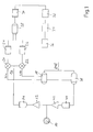
Fig. 1 ein schematisches Blockschaltbild der erfindungsgemäßen Vorrichtung zur analytischen oder therapeutischen Ultraschallsonographie gemäß einer bevorzugten Ausführungsform.Fig. 1 is a schematic block diagram of the invention Device for analytical or therapeutic ultrasound ultrasound according to a preferred embodiment.
Das Ausgangssignal einer in ansonsten bekannter Weise am
Kopf eines Patienten befestigten Ultraschallsonde 10 (typische
Betriebsfrequenz 2 oder 2,5 MHz) wird über einen Vorverstärker
12 auf der Empfangsseite einer Analog-Digital-Wandlereinheit
14 zugeführt, welche das verstärkte Empfangssignal
schnell und mit hoher Auflösung (typische Signalfrequenz
am Ausgang des AD-Wandlers 14: 12 MHz) digitalisiert
und einem digitalen Mischer 16 zuführt, welcher,
getrennt für einen Sinusanteil und einen Cosinusanteil, das
digitale Eingangssignal mit der Sinuskomponente bzw. der
Cosinuskomponente eines von einem Signalerzeuger 18 auf der
der Sondenfrequenz entsprechenden Trägerfrequenz erzeugten
Mischersignals mischt.The output signal in an otherwise known manner on
Head of a patient attached ultrasound probe 10 (typical
Operating frequency 2 or 2.5 MHz) is via a
Genauer gesagt wird in dem digitalen Mischer 16 mit Hilfe
von dem Sinus- bzw. dem Cosinuszweig jeweils zugeordneten
digitalen Multiplizierern 20, 22 das digitale Multiplikationsprodukt
des digitalisierten Empfangssignals (aus der
Einheit 14) sowie der Sinus- bzw. Cosinuskomponente des von
der Einheit 18 erzeugten Trägerfrequenzsignals gebildet, so
dass, in der bekannten Weise, am Ausgangs der Multiplizierer
20, 22 die Doppler-Mischfrequenzen gebildet werden, wobei
dann jeweils nachgeschaltete digitale Filtereinheiten
24, 26, als Tiefpaß wirkend, das gewünschte, dem Dopplershift
entsprechende Signal (entsprechend der Differenz
von Eingangssignal und Mischerfrequenz) erzeugen. Konkret
sind diese Filter als die Datenrate reduzierende FIR-Filter
realisiert und bewirken eine Reduzierung der Datenrate von
1:2, so dass einer nachgeschalteten digitalen Multiplexereinheit
28 zwei 6 MHz-Datenströme zufließen.More specifically, in the
Die Multiplexereinheit 28 erzeugt aus diesen Signalen ein 6
MHz Ausgangssignal, welches dann in einer nachgeschalteten
digitalen Tiefpaßfilterstufe 30 nochmals in der Datenrate
um 1:4 reduziert wird, so dass einer nachgeschalteten Sample-Speichereinheit
32 als Signalaufbereitungseinheit im
Sinne der Erfindung Digitalsignale einer Datenrate von ca.
1,5 MHz anliegen. Mit einer Auflösung von ca. einem Millimeter
(bezogen auf die Schallgeschwindigkeit in Wasser)
liegen typische, über einen verbundenen Hostrechner (nicht
gezeigt) einstellbare Tiefen der Ultraschallmessung zwischen
20 und 150 mm, wobei, wie beschrieben, die eingesetzte
digitale Mischertechnologie für vollständige Linearität
entlang dieses Bereiches sorgt. Besonders bevorzugt ist es,
geeignet vorgewählte bzw. voreingestellte Tiefen durch entsprechende
Ansteuerung dieser Sample-Speichereinheit als
Werte unmittelbar auszulesen und einer gesonderten Verarbeitung,
etwa zur M-Mode-Darstellung, zuzuleiten.The
Der Gesamtdatenstrom tritt zudem in einen nachgeschalteten
FIFO-Pufferspeicher 34 und von diesem in eine Rechnerschnittstelle
36 ein, welche, z.B. als PCI-Schnittstelle,
die Verbindung zu handelsüblicher PC-Rechnerinfrastruktur
herstellt und die vollständige signaltechnische Aufbereitung
und Darstellung des Dopplersignals in ansonsten bekannter
Weise ermöglicht.The total data stream also enters a downstream one
Senderseitig sorgt der digitale Signalerzeuger 18 zudem dafür,
das PRF-Signal für eine nachgeschaltete Signalformereinheit
38 zur Ansteuerung bereitzustellen, wobei das
Ausgangssignal dieser Einheit (sogenanntes Burstsignal)
dann über eine Digital-Analog-Wandlereinheit 40 und einen
nachgeschalteten Leistungsverstärker 42 an die Ultraschallsonde
10 angelegt wird.On the transmitter side, the
Genauer gesagt ist die mit der Einheit 38 realisierte digitale
Signalformung programmierbar und wird, ebenso wie die
Signalvorverarbeitung auf Empfangsseite wie obenstehend
beschrieben, durch die verbundene Hostrechnereinheit geeignet
programmtechnisch gesteuert. Die Einheiten 18 und 38
empfangen zudem eine geeignet gewählte Referenzfrequenz
fref (z.B. 48 MHz).More specifically, the digital one realized with the
Konkret wird in der praktischen Realisierung die digitale
Mischerelektronik (d.h. Einheiten 20, 22) samt Impulsgenerator
18 und digitalem Signalformer 38 als Digitalbaustein
integriert und liegt typischerweise als geeignet konfigurierter
Chip vor, so dass, zusammen mit geeignet durch den
Rechner implementierten Filtereinheiten bzw. der Multiplexer-
und der Sample-Speichereinheit, die erfindungsgemäße
Vorrichtung herstellungstechnisch einfach realisierbar ist
und praktisch keinen manuellen Kalibrierungs- bzw. Einstellaufwand
erfordert.In practice, the digital becomes concrete
Mixer electronics (
Im Ergebnis läßt sich durch die vorliegende Erfindung, verdeutlicht am Ausführungsbeispiel der Fig. 1, in überraschend einfacher und flexibler Weise eine Dopplerdemodulation realisieren, welche, in Abkehr von der bislang ausschließlich im Diagnostikbereich benutzten analogen Technologie in bisher ungeahnter Weise Linearität entlang des gesamten nutzbaren Amplituden- und Frequenzbereiches mit lediglich von der digitalen Auflösung bestimmter Rauscharmut kombiniert.The result can be illustrated by the present invention 1 in the embodiment of FIG Doppler demodulation in a simple and flexible manner realize which, in deviation from the so far exclusively analog technology used in diagnostics in an unprecedented way linearity along the entire usable amplitude and frequency range with only from the digital resolution of certain low noise levels combined.
Claims (12)
einer zum Verbinden mit einer Ultraschallsonde (10) zum Erzeugen von Ultraschallsignalen sowie zum Empfangen reflektierter Ultraschallsignale ausgebildeten Ultraschalleinheit,
die einen Impulsgenerator (18) für die sendeseitig erzeugten periodischen Ultraschallsignale sowie empfangsseitig eine Mischereinheit (16) und eine Filtereinheit (24,26,30) aufweist und zum Verbinden mit einer Signalauswerteeinheit (PC) zum Aufbereiten und visuellen Darstellen von aus den reflektierten Ultraschallsignalen erzeugten Daten eingerichtet ist,
dadurch gekennzeichnet, dass
der Ultraschallsonde empfangsseitig eine Analog-Digital-Wandlereinheit (14) nachgeschaltet ist, deren digitales Ausgangssignal in der als digitaler Mischer ausgebildeten Mischereinheit (16,20,22) mit einem Mischersignal des Impulsgenerators (18) digital gemischt werden kann.Device for diagnostic or therapeutic ultrasound ultrasound with
an ultrasound unit designed to connect to an ultrasound probe (10) for generating ultrasound signals and for receiving reflected ultrasound signals,
which has a pulse generator (18) for the periodic ultrasound signals generated on the transmission side and a mixer unit (16) and a filter unit (24,26,30) on the receiving side and for connection to a signal evaluation unit (PC) for processing and visual representation of those generated from the reflected ultrasound signals Data is set up
characterized in that
An analog-digital converter unit (14) is connected downstream of the ultrasound probe, the digital output signal of which can be digitally mixed in the mixer unit (16, 20, 22) designed as a digital mixer with a mixer signal from the pulse generator (18).
Applications Claiming Priority (2)
| Application Number | Priority Date | Filing Date | Title |
|---|---|---|---|
| DE20200617U DE20200617U1 (en) | 2002-01-15 | 2002-01-15 | Device for diagnostic or therapeutic ultrasound sonography |
| DE20200617U | 2002-01-15 |
Publications (3)
| Publication Number | Publication Date |
|---|---|
| EP1327416A2 true EP1327416A2 (en) | 2003-07-16 |
| EP1327416A3 EP1327416A3 (en) | 2005-03-30 |
| EP1327416B1 EP1327416B1 (en) | 2007-06-13 |
Family
ID=7966626
Family Applications (1)
| Application Number | Title | Priority Date | Filing Date |
|---|---|---|---|
| EP03000822A Expired - Lifetime EP1327416B1 (en) | 2002-01-15 | 2003-01-15 | Device for the ultrasound sonography |
Country Status (3)
| Country | Link |
|---|---|
| EP (1) | EP1327416B1 (en) |
| AT (1) | ATE364352T1 (en) |
| DE (3) | DE20200617U1 (en) |
Families Citing this family (1)
| Publication number | Priority date | Publication date | Assignee | Title |
|---|---|---|---|---|
| US20120165675A1 (en) * | 2003-05-21 | 2012-06-28 | Paul David Syme | Method For Diagnosis And Treatment Of Vessel Occulsion |
Citations (5)
| Publication number | Priority date | Publication date | Assignee | Title |
|---|---|---|---|---|
| US4975885A (en) * | 1988-09-30 | 1990-12-04 | Siemens Aktiengesellschaft | Digital input stage for an ultrasound apparatus |
| US5437281A (en) * | 1992-01-14 | 1995-08-01 | Diasonics Ultrasound, Inc. | Direct demodulation in ultrasound instruments |
| US5515727A (en) * | 1992-09-22 | 1996-05-14 | Hitachi Medical Corporation | Ultrasound signal processor |
| DE19716810A1 (en) * | 1997-04-22 | 1998-11-05 | Dwl Elektron Systeme Gmbh | Device and method for detecting ultrasound signals reflected on a fluid stream |
| US6248071B1 (en) * | 2000-01-28 | 2001-06-19 | U-Systems, Inc. | Demodulating wide-band ultrasound signals |
-
2002
- 2002-01-15 DE DE20200617U patent/DE20200617U1/en not_active Expired - Lifetime
-
2003
- 2003-01-15 AT AT03000822T patent/ATE364352T1/en not_active IP Right Cessation
- 2003-01-15 DE DE10301337A patent/DE10301337A1/en not_active Withdrawn
- 2003-01-15 EP EP03000822A patent/EP1327416B1/en not_active Expired - Lifetime
- 2003-01-15 DE DE50307441T patent/DE50307441D1/en not_active Expired - Lifetime
Patent Citations (5)
| Publication number | Priority date | Publication date | Assignee | Title |
|---|---|---|---|---|
| US4975885A (en) * | 1988-09-30 | 1990-12-04 | Siemens Aktiengesellschaft | Digital input stage for an ultrasound apparatus |
| US5437281A (en) * | 1992-01-14 | 1995-08-01 | Diasonics Ultrasound, Inc. | Direct demodulation in ultrasound instruments |
| US5515727A (en) * | 1992-09-22 | 1996-05-14 | Hitachi Medical Corporation | Ultrasound signal processor |
| DE19716810A1 (en) * | 1997-04-22 | 1998-11-05 | Dwl Elektron Systeme Gmbh | Device and method for detecting ultrasound signals reflected on a fluid stream |
| US6248071B1 (en) * | 2000-01-28 | 2001-06-19 | U-Systems, Inc. | Demodulating wide-band ultrasound signals |
Also Published As
| Publication number | Publication date |
|---|---|
| EP1327416A3 (en) | 2005-03-30 |
| DE50307441D1 (en) | 2007-07-26 |
| ATE364352T1 (en) | 2007-07-15 |
| DE20200617U1 (en) | 2002-06-13 |
| DE10301337A1 (en) | 2003-09-18 |
| EP1327416B1 (en) | 2007-06-13 |
Similar Documents
| Publication | Publication Date | Title |
|---|---|---|
| DE3829999C2 (en) | ||
| DE3827513C2 (en) | ||
| DE2811544C3 (en) | Ultrasonic transmitter / receiver | |
| DE3734571C2 (en) | Ultrasound diagnostic device | |
| DE3702355C2 (en) | ||
| DE3241670C2 (en) | Device and method for determining the blood flow rate and for displaying biological tissue structures | |
| DE2645738A1 (en) | ULTRASONIC BEAM SCANNING | |
| DE10039346B4 (en) | A method and apparatus for dynamic noise reduction for a Doppler audio output signal | |
| EP0204192B1 (en) | Circuit arrangement for registering heart beat motion | |
| DE2920826A1 (en) | ULTRASONIC IMAGING SYSTEM | |
| EP1795890A1 (en) | Method and device for ultrasonically detecting discontinuities in a material area | |
| DE112010003150T5 (en) | Ultrasonografievorrichtung | |
| DE19526210C2 (en) | Medical Doppler ultrasound machine | |
| EP1474708A1 (en) | Locating device and corresponding method | |
| DE19733091B4 (en) | Device and method for embolic detection | |
| DE3121781A1 (en) | METHOD AND DEVICE FOR MEASURING THE LEVEL OF A FLOWING GOOD OR MATERIAL | |
| DE2843985C3 (en) | Ultrasonic diagnostic device | |
| EP1327416B1 (en) | Device for the ultrasound sonography | |
| DE1473699A1 (en) | Measuring device working on the basis of the propagation of sound waves in the media to be examined | |
| DE2919024A1 (en) | Ultrasonic direction and depth indicator - uses beam scanning providing intersecting picture display on screen for injection needle or probe | |
| DE19757466A1 (en) | Ultrasonic imaging device operating method for preventing aliasing | |
| DE19521197A1 (en) | Arrangement and method for simultaneous real-time ultrasound imaging of biological tissues and for measuring the speed of the blood flow | |
| DE1812017C3 (en) | Arrangement for measuring the internal dimensions of cavities in the living body | |
| DE19716810B4 (en) | Apparatus and method for detecting ultrasonic signals reflected from a fluid stream | |
| DE3219223A1 (en) | Device for ultrasonic scanning |
Legal Events
| Date | Code | Title | Description |
|---|---|---|---|
| PUAI | Public reference made under article 153(3) epc to a published international application that has entered the european phase |
Free format text: ORIGINAL CODE: 0009012 |
|
| AK | Designated contracting states |
Designated state(s): AT BE BG CH CY CZ DE DK EE ES FI FR GB GR HU IE IT LI LU MC NL PT SE SI SK TR |
|
| AX | Request for extension of the european patent |
Extension state: AL LT LV MK RO |
|
| PUAL | Search report despatched |
Free format text: ORIGINAL CODE: 0009013 |
|
| AK | Designated contracting states |
Kind code of ref document: A3 Designated state(s): AT BE BG CH CY CZ DE DK EE ES FI FR GB GR HU IE IT LI LU MC NL PT SE SI SK TR |
|
| AX | Request for extension of the european patent |
Extension state: AL LT LV MK RO |
|
| 17P | Request for examination filed |
Effective date: 20050922 |
|
| AKX | Designation fees paid |
Designated state(s): AT BE BG CH CY CZ DE DK EE ES FI FR GB GR HU IE IT LI LU MC NL PT SE SI SK TR |
|
| RAP1 | Party data changed (applicant data changed or rights of an application transferred) |
Owner name: COMPUMEDICS GERMANY GMBH |
|
| GRAP | Despatch of communication of intention to grant a patent |
Free format text: ORIGINAL CODE: EPIDOSNIGR1 |
|
| GRAS | Grant fee paid |
Free format text: ORIGINAL CODE: EPIDOSNIGR3 |
|
| GRAA | (expected) grant |
Free format text: ORIGINAL CODE: 0009210 |
|
| AK | Designated contracting states |
Kind code of ref document: B1 Designated state(s): AT BE BG CH CY CZ DE DK EE ES FI FR GB GR HU IE IT LI LU MC NL PT SE SI SK TR |
|
| REG | Reference to a national code |
Ref country code: GB Ref legal event code: FG4D Free format text: NOT ENGLISH |
|
| REG | Reference to a national code |
Ref country code: CH Ref legal event code: EP |
|
| REG | Reference to a national code |
Ref country code: IE Ref legal event code: FG4D Free format text: LANGUAGE OF EP DOCUMENT: GERMAN |
|
| REF | Corresponds to: |
Ref document number: 50307441 Country of ref document: DE Date of ref document: 20070726 Kind code of ref document: P |
|
| PG25 | Lapsed in a contracting state [announced via postgrant information from national office to epo] |
Ref country code: SE Free format text: LAPSE BECAUSE OF FAILURE TO SUBMIT A TRANSLATION OF THE DESCRIPTION OR TO PAY THE FEE WITHIN THE PRESCRIBED TIME-LIMIT Effective date: 20070913 |
|
| GBT | Gb: translation of ep patent filed (gb section 77(6)(a)/1977) |
Effective date: 20070829 |
|
| REG | Reference to a national code |
Ref country code: CH Ref legal event code: NV Representative=s name: HIEBSCH & PEEGE AG PATENTANWAELTE |
|
| NLV1 | Nl: lapsed or annulled due to failure to fulfill the requirements of art. 29p and 29m of the patents act | ||
| REG | Reference to a national code |
Ref country code: IE Ref legal event code: FD4D |
|
| PG25 | Lapsed in a contracting state [announced via postgrant information from national office to epo] |
Ref country code: BG Free format text: LAPSE BECAUSE OF FAILURE TO SUBMIT A TRANSLATION OF THE DESCRIPTION OR TO PAY THE FEE WITHIN THE PRESCRIBED TIME-LIMIT Effective date: 20070913 Ref country code: SI Free format text: LAPSE BECAUSE OF FAILURE TO SUBMIT A TRANSLATION OF THE DESCRIPTION OR TO PAY THE FEE WITHIN THE PRESCRIBED TIME-LIMIT Effective date: 20070613 Ref country code: NL Free format text: LAPSE BECAUSE OF FAILURE TO SUBMIT A TRANSLATION OF THE DESCRIPTION OR TO PAY THE FEE WITHIN THE PRESCRIBED TIME-LIMIT Effective date: 20070613 Ref country code: IE Free format text: LAPSE BECAUSE OF FAILURE TO SUBMIT A TRANSLATION OF THE DESCRIPTION OR TO PAY THE FEE WITHIN THE PRESCRIBED TIME-LIMIT Effective date: 20070613 Ref country code: ES Free format text: LAPSE BECAUSE OF FAILURE TO SUBMIT A TRANSLATION OF THE DESCRIPTION OR TO PAY THE FEE WITHIN THE PRESCRIBED TIME-LIMIT Effective date: 20070924 Ref country code: CZ Free format text: LAPSE BECAUSE OF FAILURE TO SUBMIT A TRANSLATION OF THE DESCRIPTION OR TO PAY THE FEE WITHIN THE PRESCRIBED TIME-LIMIT Effective date: 20070613 Ref country code: PT Free format text: LAPSE BECAUSE OF FAILURE TO SUBMIT A TRANSLATION OF THE DESCRIPTION OR TO PAY THE FEE WITHIN THE PRESCRIBED TIME-LIMIT Effective date: 20071113 |
|
| REG | Reference to a national code |
Ref country code: CH Ref legal event code: PFA Owner name: COMPUMEDICS GERMANY GMBH Free format text: COMPUMEDICS GERMANY GMBH#JOSEF-SCHUETTLER-STRASSE 2#78224 SINGEN (DE) -TRANSFER TO- COMPUMEDICS GERMANY GMBH#JOSEF-SCHUETTLER-STRASSE 2#78224 SINGEN (DE) |
|
| EN | Fr: translation not filed | ||
| PG25 | Lapsed in a contracting state [announced via postgrant information from national office to epo] |
Ref country code: SK Free format text: LAPSE BECAUSE OF FAILURE TO SUBMIT A TRANSLATION OF THE DESCRIPTION OR TO PAY THE FEE WITHIN THE PRESCRIBED TIME-LIMIT Effective date: 20070613 |
|
| PLBE | No opposition filed within time limit |
Free format text: ORIGINAL CODE: 0009261 |
|
| STAA | Information on the status of an ep patent application or granted ep patent |
Free format text: STATUS: NO OPPOSITION FILED WITHIN TIME LIMIT |
|
| PG25 | Lapsed in a contracting state [announced via postgrant information from national office to epo] |
Ref country code: IT Free format text: LAPSE BECAUSE OF FAILURE TO SUBMIT A TRANSLATION OF THE DESCRIPTION OR TO PAY THE FEE WITHIN THE PRESCRIBED TIME-LIMIT Effective date: 20070613 Ref country code: DK Free format text: LAPSE BECAUSE OF FAILURE TO SUBMIT A TRANSLATION OF THE DESCRIPTION OR TO PAY THE FEE WITHIN THE PRESCRIBED TIME-LIMIT Effective date: 20070613 Ref country code: GR Free format text: LAPSE BECAUSE OF FAILURE TO SUBMIT A TRANSLATION OF THE DESCRIPTION OR TO PAY THE FEE WITHIN THE PRESCRIBED TIME-LIMIT Effective date: 20070914 |
|
| 26N | No opposition filed |
Effective date: 20080314 |
|
| BERE | Be: lapsed |
Owner name: COMPUMEDICS GERMANY G.M.B.H. Effective date: 20080131 |
|
| PG25 | Lapsed in a contracting state [announced via postgrant information from national office to epo] |
Ref country code: FR Free format text: LAPSE BECAUSE OF FAILURE TO SUBMIT A TRANSLATION OF THE DESCRIPTION OR TO PAY THE FEE WITHIN THE PRESCRIBED TIME-LIMIT Effective date: 20080208 |
|
| PG25 | Lapsed in a contracting state [announced via postgrant information from national office to epo] |
Ref country code: MC Free format text: LAPSE BECAUSE OF NON-PAYMENT OF DUE FEES Effective date: 20080131 |
|
| PG25 | Lapsed in a contracting state [announced via postgrant information from national office to epo] |
Ref country code: EE Free format text: LAPSE BECAUSE OF FAILURE TO SUBMIT A TRANSLATION OF THE DESCRIPTION OR TO PAY THE FEE WITHIN THE PRESCRIBED TIME-LIMIT Effective date: 20070613 |
|
| PG25 | Lapsed in a contracting state [announced via postgrant information from national office to epo] |
Ref country code: FI Free format text: LAPSE BECAUSE OF FAILURE TO SUBMIT A TRANSLATION OF THE DESCRIPTION OR TO PAY THE FEE WITHIN THE PRESCRIBED TIME-LIMIT Effective date: 20070613 Ref country code: BE Free format text: LAPSE BECAUSE OF NON-PAYMENT OF DUE FEES Effective date: 20080131 |
|
| PG25 | Lapsed in a contracting state [announced via postgrant information from national office to epo] |
Ref country code: AT Free format text: LAPSE BECAUSE OF NON-PAYMENT OF DUE FEES Effective date: 20080115 |
|
| PG25 | Lapsed in a contracting state [announced via postgrant information from national office to epo] |
Ref country code: CY Free format text: LAPSE BECAUSE OF FAILURE TO SUBMIT A TRANSLATION OF THE DESCRIPTION OR TO PAY THE FEE WITHIN THE PRESCRIBED TIME-LIMIT Effective date: 20070613 |
|
| PG25 | Lapsed in a contracting state [announced via postgrant information from national office to epo] |
Ref country code: HU Free format text: LAPSE BECAUSE OF FAILURE TO SUBMIT A TRANSLATION OF THE DESCRIPTION OR TO PAY THE FEE WITHIN THE PRESCRIBED TIME-LIMIT Effective date: 20071214 Ref country code: LU Free format text: LAPSE BECAUSE OF NON-PAYMENT OF DUE FEES Effective date: 20080115 |
|
| PG25 | Lapsed in a contracting state [announced via postgrant information from national office to epo] |
Ref country code: TR Free format text: LAPSE BECAUSE OF FAILURE TO SUBMIT A TRANSLATION OF THE DESCRIPTION OR TO PAY THE FEE WITHIN THE PRESCRIBED TIME-LIMIT Effective date: 20070613 |
|
| PGFP | Annual fee paid to national office [announced via postgrant information from national office to epo] |
Ref country code: GB Payment date: 20180306 Year of fee payment: 16 Ref country code: CH Payment date: 20180306 Year of fee payment: 16 |
|
| PGFP | Annual fee paid to national office [announced via postgrant information from national office to epo] |
Ref country code: DE Payment date: 20190131 Year of fee payment: 17 |
|
| REG | Reference to a national code |
Ref country code: CH Ref legal event code: PL |
|
| GBPC | Gb: european patent ceased through non-payment of renewal fee |
Effective date: 20190115 |
|
| PG25 | Lapsed in a contracting state [announced via postgrant information from national office to epo] |
Ref country code: GB Free format text: LAPSE BECAUSE OF NON-PAYMENT OF DUE FEES Effective date: 20190115 Ref country code: CH Free format text: LAPSE BECAUSE OF NON-PAYMENT OF DUE FEES Effective date: 20190131 Ref country code: LI Free format text: LAPSE BECAUSE OF NON-PAYMENT OF DUE FEES Effective date: 20190131 |
|
| REG | Reference to a national code |
Ref country code: DE Ref legal event code: R119 Ref document number: 50307441 Country of ref document: DE |
|
| PG25 | Lapsed in a contracting state [announced via postgrant information from national office to epo] |
Ref country code: DE Free format text: LAPSE BECAUSE OF NON-PAYMENT OF DUE FEES Effective date: 20200801 |