EP1329204B1 - Endoluminal vascular prosthesis - Google Patents
Endoluminal vascular prosthesis Download PDFInfo
- Publication number
- EP1329204B1 EP1329204B1 EP03250104A EP03250104A EP1329204B1 EP 1329204 B1 EP1329204 B1 EP 1329204B1 EP 03250104 A EP03250104 A EP 03250104A EP 03250104 A EP03250104 A EP 03250104A EP 1329204 B1 EP1329204 B1 EP 1329204B1
- Authority
- EP
- European Patent Office
- Prior art keywords
- prosthesis
- stent
- artery
- aneurysm
- matrix
- Prior art date
- Legal status (The legal status is an assumption and is not a legal conclusion. Google has not performed a legal analysis and makes no representation as to the accuracy of the status listed.)
- Expired - Lifetime
Links
- 230000002792 vascular Effects 0.000 title description 3
- 206010002329 Aneurysm Diseases 0.000 claims abstract description 84
- 210000001367 artery Anatomy 0.000 claims abstract description 76
- 238000011144 upstream manufacturing Methods 0.000 claims abstract description 29
- 239000000463 material Substances 0.000 claims description 96
- 239000011159 matrix material Substances 0.000 claims description 39
- 238000004873 anchoring Methods 0.000 claims description 31
- 239000012530 fluid Substances 0.000 description 60
- 238000000034 method Methods 0.000 description 27
- 239000008280 blood Substances 0.000 description 26
- 210000004369 blood Anatomy 0.000 description 26
- 208000002223 abdominal aortic aneurysm Diseases 0.000 description 22
- 239000003566 sealing material Substances 0.000 description 21
- 208000007474 aortic aneurysm Diseases 0.000 description 20
- 210000002254 renal artery Anatomy 0.000 description 20
- 239000000835 fiber Substances 0.000 description 17
- 210000003090 iliac artery Anatomy 0.000 description 16
- 238000007789 sealing Methods 0.000 description 15
- 239000010432 diamond Substances 0.000 description 14
- 230000010339 dilation Effects 0.000 description 13
- 210000000709 aorta Anatomy 0.000 description 12
- 230000008439 repair process Effects 0.000 description 11
- 239000003550 marker Substances 0.000 description 8
- 238000001356 surgical procedure Methods 0.000 description 8
- 229910003460 diamond Inorganic materials 0.000 description 7
- 239000006260 foam Substances 0.000 description 7
- 230000006870 function Effects 0.000 description 7
- 238000005192 partition Methods 0.000 description 7
- 229920000728 polyester Polymers 0.000 description 7
- -1 polyethylene Polymers 0.000 description 7
- 229920002635 polyurethane Polymers 0.000 description 7
- 239000004814 polyurethane Substances 0.000 description 7
- 238000013461 design Methods 0.000 description 6
- 230000037361 pathway Effects 0.000 description 6
- 239000005020 polyethylene terephthalate Substances 0.000 description 6
- 239000002243 precursor Substances 0.000 description 6
- 239000000853 adhesive Substances 0.000 description 5
- 230000001070 adhesive effect Effects 0.000 description 5
- 210000000702 aorta abdominal Anatomy 0.000 description 5
- 239000013060 biological fluid Substances 0.000 description 5
- 210000001736 capillary Anatomy 0.000 description 5
- 230000000295 complement effect Effects 0.000 description 5
- 210000001105 femoral artery Anatomy 0.000 description 5
- 210000000056 organ Anatomy 0.000 description 5
- 210000003462 vein Anatomy 0.000 description 5
- 229920004934 Dacron® Polymers 0.000 description 4
- 238000002399 angioplasty Methods 0.000 description 4
- 210000002376 aorta thoracic Anatomy 0.000 description 4
- 230000008901 benefit Effects 0.000 description 4
- 230000017531 blood circulation Effects 0.000 description 4
- 210000004204 blood vessel Anatomy 0.000 description 4
- 210000004027 cell Anatomy 0.000 description 4
- 229920000295 expanded polytetrafluoroethylene Polymers 0.000 description 4
- 238000001727 in vivo Methods 0.000 description 4
- 229910001000 nickel titanium Inorganic materials 0.000 description 4
- 239000010935 stainless steel Substances 0.000 description 4
- 229910001220 stainless steel Inorganic materials 0.000 description 4
- 210000000115 thoracic cavity Anatomy 0.000 description 4
- 102000008186 Collagen Human genes 0.000 description 3
- 108010035532 Collagen Proteins 0.000 description 3
- 201000008982 Thoracic Aortic Aneurysm Diseases 0.000 description 3
- 230000009286 beneficial effect Effects 0.000 description 3
- 229920001436 collagen Polymers 0.000 description 3
- 238000004891 communication Methods 0.000 description 3
- 210000003038 endothelium Anatomy 0.000 description 3
- 239000006261 foam material Substances 0.000 description 3
- 210000002216 heart Anatomy 0.000 description 3
- 230000007774 longterm Effects 0.000 description 3
- 230000007246 mechanism Effects 0.000 description 3
- 229910052751 metal Inorganic materials 0.000 description 3
- 239000002184 metal Substances 0.000 description 3
- HLXZNVUGXRDIFK-UHFFFAOYSA-N nickel titanium Chemical compound [Ti].[Ti].[Ti].[Ti].[Ti].[Ti].[Ti].[Ti].[Ti].[Ti].[Ti].[Ni].[Ni].[Ni].[Ni].[Ni].[Ni].[Ni].[Ni].[Ni].[Ni].[Ni].[Ni].[Ni].[Ni] HLXZNVUGXRDIFK-UHFFFAOYSA-N 0.000 description 3
- 229920001343 polytetrafluoroethylene Polymers 0.000 description 3
- 210000005166 vasculature Anatomy 0.000 description 3
- 239000002033 PVDF binder Substances 0.000 description 2
- 239000004743 Polypropylene Substances 0.000 description 2
- 239000004809 Teflon Substances 0.000 description 2
- 229920006362 Teflon® Polymers 0.000 description 2
- 208000007536 Thrombosis Diseases 0.000 description 2
- 230000003187 abdominal effect Effects 0.000 description 2
- 230000001154 acute effect Effects 0.000 description 2
- 229910045601 alloy Inorganic materials 0.000 description 2
- 239000000956 alloy Substances 0.000 description 2
- 210000003484 anatomy Anatomy 0.000 description 2
- 230000010102 embolization Effects 0.000 description 2
- 238000005516 engineering process Methods 0.000 description 2
- 239000003292 glue Substances 0.000 description 2
- 239000011796 hollow space material Substances 0.000 description 2
- 239000007943 implant Substances 0.000 description 2
- 210000003141 lower extremity Anatomy 0.000 description 2
- 210000001165 lymph node Anatomy 0.000 description 2
- 238000004519 manufacturing process Methods 0.000 description 2
- 229910001092 metal group alloy Inorganic materials 0.000 description 2
- 230000005012 migration Effects 0.000 description 2
- 238000013508 migration Methods 0.000 description 2
- 210000003463 organelle Anatomy 0.000 description 2
- 230000036961 partial effect Effects 0.000 description 2
- 230000001575 pathological effect Effects 0.000 description 2
- BASFCYQUMIYNBI-UHFFFAOYSA-N platinum Chemical compound [Pt] BASFCYQUMIYNBI-UHFFFAOYSA-N 0.000 description 2
- 229920000139 polyethylene terephthalate Polymers 0.000 description 2
- 229920001155 polypropylene Polymers 0.000 description 2
- 229920001296 polysiloxane Polymers 0.000 description 2
- 239000004810 polytetrafluoroethylene Substances 0.000 description 2
- 229920002981 polyvinylidene fluoride Polymers 0.000 description 2
- 230000002265 prevention Effects 0.000 description 2
- 238000011084 recovery Methods 0.000 description 2
- 230000002829 reductive effect Effects 0.000 description 2
- 229920006395 saturated elastomer Polymers 0.000 description 2
- 229910052715 tantalum Inorganic materials 0.000 description 2
- GUVRBAGPIYLISA-UHFFFAOYSA-N tantalum atom Chemical compound [Ta] GUVRBAGPIYLISA-UHFFFAOYSA-N 0.000 description 2
- 210000001519 tissue Anatomy 0.000 description 2
- 238000011282 treatment Methods 0.000 description 2
- 238000003466 welding Methods 0.000 description 2
- 229910000619 316 stainless steel Inorganic materials 0.000 description 1
- 102000009027 Albumins Human genes 0.000 description 1
- 108010088751 Albumins Proteins 0.000 description 1
- 208000017667 Chronic Disease Diseases 0.000 description 1
- 208000034657 Convalescence Diseases 0.000 description 1
- 208000002251 Dissecting Aneurysm Diseases 0.000 description 1
- 208000005189 Embolism Diseases 0.000 description 1
- 208000001750 Endoleak Diseases 0.000 description 1
- 102000009123 Fibrin Human genes 0.000 description 1
- 108010073385 Fibrin Proteins 0.000 description 1
- BWGVNKXGVNDBDI-UHFFFAOYSA-N Fibrin monomer Chemical compound CNC(=O)CNC(=O)CN BWGVNKXGVNDBDI-UHFFFAOYSA-N 0.000 description 1
- 206010016717 Fistula Diseases 0.000 description 1
- 206010022680 Intestinal ischaemia Diseases 0.000 description 1
- 208000019693 Lung disease Diseases 0.000 description 1
- 241001465754 Metazoa Species 0.000 description 1
- 206010033799 Paralysis Diseases 0.000 description 1
- 239000004698 Polyethylene Substances 0.000 description 1
- 229910001260 Pt alloy Inorganic materials 0.000 description 1
- 208000001647 Renal Insufficiency Diseases 0.000 description 1
- 208000002847 Surgical Wound Diseases 0.000 description 1
- 229910001362 Ta alloys Inorganic materials 0.000 description 1
- HZEWFHLRYVTOIW-UHFFFAOYSA-N [Ti].[Ni] Chemical compound [Ti].[Ni] HZEWFHLRYVTOIW-UHFFFAOYSA-N 0.000 description 1
- 210000000683 abdominal cavity Anatomy 0.000 description 1
- 230000002159 abnormal effect Effects 0.000 description 1
- 210000004381 amniotic fluid Anatomy 0.000 description 1
- 238000013459 approach Methods 0.000 description 1
- 230000000712 assembly Effects 0.000 description 1
- 238000000429 assembly Methods 0.000 description 1
- 239000000560 biocompatible material Substances 0.000 description 1
- 230000015572 biosynthetic process Effects 0.000 description 1
- 230000000903 blocking effect Effects 0.000 description 1
- 230000036760 body temperature Effects 0.000 description 1
- 210000002302 brachial artery Anatomy 0.000 description 1
- 210000003850 cellular structure Anatomy 0.000 description 1
- 230000008859 change Effects 0.000 description 1
- 230000035602 clotting Effects 0.000 description 1
- 239000011248 coating agent Substances 0.000 description 1
- 238000000576 coating method Methods 0.000 description 1
- 210000002808 connective tissue Anatomy 0.000 description 1
- 239000000470 constituent Substances 0.000 description 1
- 238000010276 construction Methods 0.000 description 1
- 230000007797 corrosion Effects 0.000 description 1
- 238000005260 corrosion Methods 0.000 description 1
- 230000001419 dependent effect Effects 0.000 description 1
- 238000011161 development Methods 0.000 description 1
- 230000000916 dilatatory effect Effects 0.000 description 1
- 230000000694 effects Effects 0.000 description 1
- 210000002889 endothelial cell Anatomy 0.000 description 1
- 230000001856 erectile effect Effects 0.000 description 1
- 230000003628 erosive effect Effects 0.000 description 1
- 208000003457 familial thoracic 1 aortic aneurysm Diseases 0.000 description 1
- 229950003499 fibrin Drugs 0.000 description 1
- 230000003890 fistula Effects 0.000 description 1
- 230000002496 gastric effect Effects 0.000 description 1
- PCHJSUWPFVWCPO-UHFFFAOYSA-N gold Chemical compound [Au] PCHJSUWPFVWCPO-UHFFFAOYSA-N 0.000 description 1
- 229910052737 gold Inorganic materials 0.000 description 1
- 239000010931 gold Substances 0.000 description 1
- 208000019622 heart disease Diseases 0.000 description 1
- 238000010438 heat treatment Methods 0.000 description 1
- 238000002513 implantation Methods 0.000 description 1
- 201000001881 impotence Diseases 0.000 description 1
- 230000006872 improvement Effects 0.000 description 1
- 208000015181 infectious disease Diseases 0.000 description 1
- 230000002401 inhibitory effect Effects 0.000 description 1
- 230000010354 integration Effects 0.000 description 1
- 230000002452 interceptive effect Effects 0.000 description 1
- 229910052741 iridium Inorganic materials 0.000 description 1
- GKOZUEZYRPOHIO-UHFFFAOYSA-N iridium atom Chemical compound [Ir] GKOZUEZYRPOHIO-UHFFFAOYSA-N 0.000 description 1
- 210000003734 kidney Anatomy 0.000 description 1
- 208000017169 kidney disease Diseases 0.000 description 1
- 201000006370 kidney failure Diseases 0.000 description 1
- 201000002818 limb ischemia Diseases 0.000 description 1
- 210000004185 liver Anatomy 0.000 description 1
- 208000019423 liver disease Diseases 0.000 description 1
- 210000004072 lung Anatomy 0.000 description 1
- 210000002751 lymph Anatomy 0.000 description 1
- 210000001365 lymphatic vessel Anatomy 0.000 description 1
- 230000036244 malformation Effects 0.000 description 1
- 238000007726 management method Methods 0.000 description 1
- 230000013011 mating Effects 0.000 description 1
- 238000002844 melting Methods 0.000 description 1
- 230000008018 melting Effects 0.000 description 1
- 239000000203 mixture Substances 0.000 description 1
- 230000004660 morphological change Effects 0.000 description 1
- 208000031225 myocardial ischemia Diseases 0.000 description 1
- 239000005445 natural material Substances 0.000 description 1
- 229910052697 platinum Inorganic materials 0.000 description 1
- 229920000573 polyethylene Polymers 0.000 description 1
- 239000002861 polymer material Substances 0.000 description 1
- 239000011148 porous material Substances 0.000 description 1
- 230000001737 promoting effect Effects 0.000 description 1
- 102000004169 proteins and genes Human genes 0.000 description 1
- 108090000623 proteins and genes Proteins 0.000 description 1
- 238000011160 research Methods 0.000 description 1
- 238000002271 resection Methods 0.000 description 1
- 238000009958 sewing Methods 0.000 description 1
- 208000020431 spinal cord injury Diseases 0.000 description 1
- 238000011272 standard treatment Methods 0.000 description 1
- 230000007847 structural defect Effects 0.000 description 1
- 238000011477 surgical intervention Methods 0.000 description 1
- 229920002994 synthetic fiber Polymers 0.000 description 1
- 230000009885 systemic effect Effects 0.000 description 1
- 238000009941 weaving Methods 0.000 description 1
Images


Classifications
-
- A—HUMAN NECESSITIES
- A61—MEDICAL OR VETERINARY SCIENCE; HYGIENE
- A61F—FILTERS IMPLANTABLE INTO BLOOD VESSELS; PROSTHESES; DEVICES PROVIDING PATENCY TO, OR PREVENTING COLLAPSING OF, TUBULAR STRUCTURES OF THE BODY, e.g. STENTS; ORTHOPAEDIC, NURSING OR CONTRACEPTIVE DEVICES; FOMENTATION; TREATMENT OR PROTECTION OF EYES OR EARS; BANDAGES, DRESSINGS OR ABSORBENT PADS; FIRST-AID KITS
- A61F2/00—Filters implantable into blood vessels; Prostheses, i.e. artificial substitutes or replacements for parts of the body; Appliances for connecting them with the body; Devices providing patency to, or preventing collapsing of, tubular structures of the body, e.g. stents
- A61F2/02—Prostheses implantable into the body
- A61F2/04—Hollow or tubular parts of organs, e.g. bladders, tracheae, bronchi or bile ducts
- A61F2/06—Blood vessels
- A61F2/07—Stent-grafts
-
- A—HUMAN NECESSITIES
- A61—MEDICAL OR VETERINARY SCIENCE; HYGIENE
- A61F—FILTERS IMPLANTABLE INTO BLOOD VESSELS; PROSTHESES; DEVICES PROVIDING PATENCY TO, OR PREVENTING COLLAPSING OF, TUBULAR STRUCTURES OF THE BODY, e.g. STENTS; ORTHOPAEDIC, NURSING OR CONTRACEPTIVE DEVICES; FOMENTATION; TREATMENT OR PROTECTION OF EYES OR EARS; BANDAGES, DRESSINGS OR ABSORBENT PADS; FIRST-AID KITS
- A61F2/00—Filters implantable into blood vessels; Prostheses, i.e. artificial substitutes or replacements for parts of the body; Appliances for connecting them with the body; Devices providing patency to, or preventing collapsing of, tubular structures of the body, e.g. stents
- A61F2/82—Devices providing patency to, or preventing collapsing of, tubular structures of the body, e.g. stents
- A61F2/848—Devices providing patency to, or preventing collapsing of, tubular structures of the body, e.g. stents having means for fixation to the vessel wall, e.g. barbs
-
- A—HUMAN NECESSITIES
- A61—MEDICAL OR VETERINARY SCIENCE; HYGIENE
- A61F—FILTERS IMPLANTABLE INTO BLOOD VESSELS; PROSTHESES; DEVICES PROVIDING PATENCY TO, OR PREVENTING COLLAPSING OF, TUBULAR STRUCTURES OF THE BODY, e.g. STENTS; ORTHOPAEDIC, NURSING OR CONTRACEPTIVE DEVICES; FOMENTATION; TREATMENT OR PROTECTION OF EYES OR EARS; BANDAGES, DRESSINGS OR ABSORBENT PADS; FIRST-AID KITS
- A61F2/00—Filters implantable into blood vessels; Prostheses, i.e. artificial substitutes or replacements for parts of the body; Appliances for connecting them with the body; Devices providing patency to, or preventing collapsing of, tubular structures of the body, e.g. stents
- A61F2/82—Devices providing patency to, or preventing collapsing of, tubular structures of the body, e.g. stents
- A61F2/86—Stents in a form characterised by the wire-like elements; Stents in the form characterised by a net-like or mesh-like structure
- A61F2/89—Stents in a form characterised by the wire-like elements; Stents in the form characterised by a net-like or mesh-like structure the wire-like elements comprising two or more adjacent rings flexibly connected by separate members
-
- A—HUMAN NECESSITIES
- A61—MEDICAL OR VETERINARY SCIENCE; HYGIENE
- A61F—FILTERS IMPLANTABLE INTO BLOOD VESSELS; PROSTHESES; DEVICES PROVIDING PATENCY TO, OR PREVENTING COLLAPSING OF, TUBULAR STRUCTURES OF THE BODY, e.g. STENTS; ORTHOPAEDIC, NURSING OR CONTRACEPTIVE DEVICES; FOMENTATION; TREATMENT OR PROTECTION OF EYES OR EARS; BANDAGES, DRESSINGS OR ABSORBENT PADS; FIRST-AID KITS
- A61F2/00—Filters implantable into blood vessels; Prostheses, i.e. artificial substitutes or replacements for parts of the body; Appliances for connecting them with the body; Devices providing patency to, or preventing collapsing of, tubular structures of the body, e.g. stents
- A61F2/82—Devices providing patency to, or preventing collapsing of, tubular structures of the body, e.g. stents
- A61F2/86—Stents in a form characterised by the wire-like elements; Stents in the form characterised by a net-like or mesh-like structure
- A61F2/90—Stents in a form characterised by the wire-like elements; Stents in the form characterised by a net-like or mesh-like structure characterised by a net-like or mesh-like structure
- A61F2/91—Stents in a form characterised by the wire-like elements; Stents in the form characterised by a net-like or mesh-like structure characterised by a net-like or mesh-like structure made from perforated sheet material or tubes, e.g. perforated by laser cuts or etched holes
- A61F2/915—Stents in a form characterised by the wire-like elements; Stents in the form characterised by a net-like or mesh-like structure characterised by a net-like or mesh-like structure made from perforated sheet material or tubes, e.g. perforated by laser cuts or etched holes with bands having a meander structure, adjacent bands being connected to each other
-
- A—HUMAN NECESSITIES
- A61—MEDICAL OR VETERINARY SCIENCE; HYGIENE
- A61F—FILTERS IMPLANTABLE INTO BLOOD VESSELS; PROSTHESES; DEVICES PROVIDING PATENCY TO, OR PREVENTING COLLAPSING OF, TUBULAR STRUCTURES OF THE BODY, e.g. STENTS; ORTHOPAEDIC, NURSING OR CONTRACEPTIVE DEVICES; FOMENTATION; TREATMENT OR PROTECTION OF EYES OR EARS; BANDAGES, DRESSINGS OR ABSORBENT PADS; FIRST-AID KITS
- A61F2/00—Filters implantable into blood vessels; Prostheses, i.e. artificial substitutes or replacements for parts of the body; Appliances for connecting them with the body; Devices providing patency to, or preventing collapsing of, tubular structures of the body, e.g. stents
- A61F2/02—Prostheses implantable into the body
- A61F2/04—Hollow or tubular parts of organs, e.g. bladders, tracheae, bronchi or bile ducts
- A61F2/06—Blood vessels
- A61F2002/061—Blood vessels provided with means for allowing access to secondary lumens
-
- A—HUMAN NECESSITIES
- A61—MEDICAL OR VETERINARY SCIENCE; HYGIENE
- A61F—FILTERS IMPLANTABLE INTO BLOOD VESSELS; PROSTHESES; DEVICES PROVIDING PATENCY TO, OR PREVENTING COLLAPSING OF, TUBULAR STRUCTURES OF THE BODY, e.g. STENTS; ORTHOPAEDIC, NURSING OR CONTRACEPTIVE DEVICES; FOMENTATION; TREATMENT OR PROTECTION OF EYES OR EARS; BANDAGES, DRESSINGS OR ABSORBENT PADS; FIRST-AID KITS
- A61F2/00—Filters implantable into blood vessels; Prostheses, i.e. artificial substitutes or replacements for parts of the body; Appliances for connecting them with the body; Devices providing patency to, or preventing collapsing of, tubular structures of the body, e.g. stents
- A61F2/02—Prostheses implantable into the body
- A61F2/04—Hollow or tubular parts of organs, e.g. bladders, tracheae, bronchi or bile ducts
- A61F2/06—Blood vessels
- A61F2002/065—Y-shaped blood vessels
- A61F2002/067—Y-shaped blood vessels modular
-
- A—HUMAN NECESSITIES
- A61—MEDICAL OR VETERINARY SCIENCE; HYGIENE
- A61F—FILTERS IMPLANTABLE INTO BLOOD VESSELS; PROSTHESES; DEVICES PROVIDING PATENCY TO, OR PREVENTING COLLAPSING OF, TUBULAR STRUCTURES OF THE BODY, e.g. STENTS; ORTHOPAEDIC, NURSING OR CONTRACEPTIVE DEVICES; FOMENTATION; TREATMENT OR PROTECTION OF EYES OR EARS; BANDAGES, DRESSINGS OR ABSORBENT PADS; FIRST-AID KITS
- A61F2/00—Filters implantable into blood vessels; Prostheses, i.e. artificial substitutes or replacements for parts of the body; Appliances for connecting them with the body; Devices providing patency to, or preventing collapsing of, tubular structures of the body, e.g. stents
- A61F2/02—Prostheses implantable into the body
- A61F2/04—Hollow or tubular parts of organs, e.g. bladders, tracheae, bronchi or bile ducts
- A61F2/06—Blood vessels
- A61F2/07—Stent-grafts
- A61F2002/075—Stent-grafts the stent being loosely attached to the graft material, e.g. by stitching
-
- A—HUMAN NECESSITIES
- A61—MEDICAL OR VETERINARY SCIENCE; HYGIENE
- A61F—FILTERS IMPLANTABLE INTO BLOOD VESSELS; PROSTHESES; DEVICES PROVIDING PATENCY TO, OR PREVENTING COLLAPSING OF, TUBULAR STRUCTURES OF THE BODY, e.g. STENTS; ORTHOPAEDIC, NURSING OR CONTRACEPTIVE DEVICES; FOMENTATION; TREATMENT OR PROTECTION OF EYES OR EARS; BANDAGES, DRESSINGS OR ABSORBENT PADS; FIRST-AID KITS
- A61F2230/00—Geometry of prostheses classified in groups A61F2/00 - A61F2/26 or A61F2/82 or A61F9/00 or A61F11/00 or subgroups thereof
- A61F2230/0002—Two-dimensional shapes, e.g. cross-sections
- A61F2230/0004—Rounded shapes, e.g. with rounded corners
- A61F2230/0013—Horseshoe-shaped, e.g. crescent-shaped, C-shaped, U-shaped
-
- A—HUMAN NECESSITIES
- A61—MEDICAL OR VETERINARY SCIENCE; HYGIENE
- A61F—FILTERS IMPLANTABLE INTO BLOOD VESSELS; PROSTHESES; DEVICES PROVIDING PATENCY TO, OR PREVENTING COLLAPSING OF, TUBULAR STRUCTURES OF THE BODY, e.g. STENTS; ORTHOPAEDIC, NURSING OR CONTRACEPTIVE DEVICES; FOMENTATION; TREATMENT OR PROTECTION OF EYES OR EARS; BANDAGES, DRESSINGS OR ABSORBENT PADS; FIRST-AID KITS
- A61F2230/00—Geometry of prostheses classified in groups A61F2/00 - A61F2/26 or A61F2/82 or A61F9/00 or A61F11/00 or subgroups thereof
- A61F2230/0002—Two-dimensional shapes, e.g. cross-sections
- A61F2230/0028—Shapes in the form of latin or greek characters
- A61F2230/005—Rosette-shaped, e.g. star-shaped
-
- A—HUMAN NECESSITIES
- A61—MEDICAL OR VETERINARY SCIENCE; HYGIENE
- A61F—FILTERS IMPLANTABLE INTO BLOOD VESSELS; PROSTHESES; DEVICES PROVIDING PATENCY TO, OR PREVENTING COLLAPSING OF, TUBULAR STRUCTURES OF THE BODY, e.g. STENTS; ORTHOPAEDIC, NURSING OR CONTRACEPTIVE DEVICES; FOMENTATION; TREATMENT OR PROTECTION OF EYES OR EARS; BANDAGES, DRESSINGS OR ABSORBENT PADS; FIRST-AID KITS
- A61F2230/00—Geometry of prostheses classified in groups A61F2/00 - A61F2/26 or A61F2/82 or A61F9/00 or A61F11/00 or subgroups thereof
- A61F2230/0063—Three-dimensional shapes
- A61F2230/0067—Three-dimensional shapes conical
-
- A—HUMAN NECESSITIES
- A61—MEDICAL OR VETERINARY SCIENCE; HYGIENE
- A61F—FILTERS IMPLANTABLE INTO BLOOD VESSELS; PROSTHESES; DEVICES PROVIDING PATENCY TO, OR PREVENTING COLLAPSING OF, TUBULAR STRUCTURES OF THE BODY, e.g. STENTS; ORTHOPAEDIC, NURSING OR CONTRACEPTIVE DEVICES; FOMENTATION; TREATMENT OR PROTECTION OF EYES OR EARS; BANDAGES, DRESSINGS OR ABSORBENT PADS; FIRST-AID KITS
- A61F2230/00—Geometry of prostheses classified in groups A61F2/00 - A61F2/26 or A61F2/82 or A61F9/00 or A61F11/00 or subgroups thereof
- A61F2230/0063—Three-dimensional shapes
- A61F2230/0073—Quadric-shaped
- A61F2230/0078—Quadric-shaped hyperboloidal
-
- A—HUMAN NECESSITIES
- A61—MEDICAL OR VETERINARY SCIENCE; HYGIENE
- A61F—FILTERS IMPLANTABLE INTO BLOOD VESSELS; PROSTHESES; DEVICES PROVIDING PATENCY TO, OR PREVENTING COLLAPSING OF, TUBULAR STRUCTURES OF THE BODY, e.g. STENTS; ORTHOPAEDIC, NURSING OR CONTRACEPTIVE DEVICES; FOMENTATION; TREATMENT OR PROTECTION OF EYES OR EARS; BANDAGES, DRESSINGS OR ABSORBENT PADS; FIRST-AID KITS
- A61F2250/00—Special features of prostheses classified in groups A61F2/00 - A61F2/26 or A61F2/82 or A61F9/00 or A61F11/00 or subgroups thereof
- A61F2250/0014—Special features of prostheses classified in groups A61F2/00 - A61F2/26 or A61F2/82 or A61F9/00 or A61F11/00 or subgroups thereof having different values of a given property or geometrical feature, e.g. mechanical property or material property, at different locations within the same prosthesis
- A61F2250/0037—Special features of prostheses classified in groups A61F2/00 - A61F2/26 or A61F2/82 or A61F9/00 or A61F11/00 or subgroups thereof having different values of a given property or geometrical feature, e.g. mechanical property or material property, at different locations within the same prosthesis differing in height or in length
Definitions
- the present invention relates to devices for repairing aneurysm, and more particularly, to percutaneously and/or intraluminally delivered devices for repairing aneurysms, such as abdominal aortic aneurysms and thoracic aortic aneurysms.
- the other two dilations are located in the iliac arteries between the aortic bifurcation and the bifurcations between the external iliacs and the internal iliacs.
- the iliac arteries are healthy between the iliac bifurcation and the aneurysms.
- a Type II C aneurysm also comprises three dilations. However, in a Type II C aneurysm, the dilations in the iliac arteries extend to the iliac bifurcation.
- endoprostheses represent a significant improvement over conventional surgical techniques
- One concern with the use of endoprostheses is the prevention of endo-leaks and the disruption of the normal fluid dynamics of the vasculature.
- the system of the present invention is intended for use when section 101 of the artery is unsuitable for anchoring a portion of the system.
- section 101 of the artery includes a junction with a second artery 103, and/or includes one or more angled sections 104 of artery.
- the stent of the first prosthesis is a collapsible, flexible, and self-expanding lattice or matrix formed from a metal or metal alloy, such as nitinol or stainless steel. Structures formed from stainless steel may be made self-expanding by configuring the stainless steel in a predetermined manner, for example, by twisting it into a braided configuration. More preferably, the stent is a tubular frame that supports a sealing material.
- the term tubular refers to any shape having a sidewall or sidewalls defining a hollow space or lumen extending therebetween; the shape may be generally cylindrical, elliptic, oval, rectangular, triangular, or any other shape. Furthermore, the shape may change or be deformable as a consequence of various forces that may press against the stent or prosthesis.
- the sealing material or gasket member may comprise any suitable material.
- Exemplary materials are composed of a biodurable and biocompatible material, including but are not limited to, open cell foam materials and closed cell foam materials.
- Exemplary materials include polyurethane, polyethylene, polytetrafluroethylene; and other various polymer materials, preferably woven or knitted, that provide a flexible structure, such as a polyester (such as that sold under the trade mark Dacron).
- Highly compressible foams are particularly preferred, preferably to keep the crimped profile low for better delivery.
- the sealing material or foam is preferably substantially impervious to blood when in a compressed state.
- the sealing material may cover one or more surfaces of the stent i.e., may be located along an interior or exterior wall, or both, and preferably extends across the proximal end or a proximal portion of the stent.
- the sealing material helps impede any blood trying to flow around the first prosthesis, e.g., between the first prosthesis and the arterial wall, and around one or more bypass prostheses after they have been deployed within the lumen of the first prosthesis (described in more detail below).
- the sealing material may be attached to the stent by any of a variety of connectors, including a plurality of conventional sutures of polyvinylidene fluoride, polypropylene, polyester (such as that sold under the trade mark Dacron), or any other suitable material and attached thereto.
- Other methods of attaching the sealing material to the stent include adhesives, ultrasonic welding, mechanical interference fit and staples.
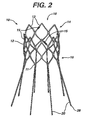
- FIGS 1 to 3 show an exemplary infra-renal sealing prosthesis 10 useful for understanding the present invention.
- Sealing prosthesis 10 includes a cylindrical or oval cross-sectional self-expanding lattice, support, or stent 12, typically made from a plurality of interconnected struts 13.
- Stent 12 defines an interior space or lumen 18 having two open ends, a proximal end 14 and a distal end 16.
- One or more markers may be optionally disposed in or on the stent between the proximal end 14 and the distal end 16.
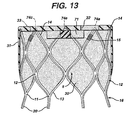
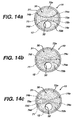
- the exemplary embodiments illustrated in Figures 13 and 14 include a thicker partition 71 in roughly an hourglass shape, although other shapes and sizes may be used.
- the partition defines at least one section 72 within the prosthesis having less material or the like, these sections being configured for receiving a proximal end of a second prosthesis, as is described in more detail below.
- partition 71 defines a first section 72a and a second section 72b; first section 72a is configured to receive a first second prosthesis 11a, and second section 72b is configured to receive a second prosthesis 11b, as described below.
- fibres, threads, filaments, straps, or the like may be desirable to include one or more fibres, threads, filaments, straps, or the like for further defining a section 72.
- the word fibre will be used as a shorthand descriptor for the element that includes fibres, threads, filaments, straps, or the like.
- the fibre, etc. assists in positioning a second prosthesis 11a or b.
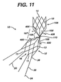
- Figures 8 , 9 , 10 and 11 show alternative configurations of a stent 10 intended for use with arterial sections unsuitable for use with a typical stent, such as that shown in Figure 2 . These stents are utilized for supra-renal anchoring.
- the stent configurations shown in Figures 8 , 9 , 10 and 11 include a first portion or matrix 12 configured to engage a downstream portion of an artery 101 (upstream of an aneurysm), and a second portion or matrix 106 configured to engage an upstream portion of the artery 302.
- matrix 106 may be configured to engage a portion of the artery 302 upstream of a second artery, such as a renal artery 103.
- the struts 13 of matrix 12 include a proximally extending bridge 107 comprising at least one elongated strut 108 that communicates with or connects to the matrix 106.
- the exemplary embodiment of the invention shown in Figure 10 includes a plurality of struts 108, for example, eight, that in combination form a straight bridge.
- the exemplary embodiment of the invention shown in Figure 11 includes a plurality of struts 108, for example, eight, that in combination form a jointed bridge, described in more detail below.
- the upstream portion, component, or prosthesis of the system may be variously configured to achieve a highly flexible structure suitable for accommodating one or more highly angled sections of an artery.
- the flexibility is achieved without creating kinks in the structure.
- the upstream portion, component, or prosthesis of the system may include open or unattached diamonds or struts, resilient struts, or the like as explained in detail subsequently.
- the stent or matrix configuration is flexible both longitudinally and radially. As used herein, longitudinal flexibility refers to the ability for a stent or matrix to shorten or elongate as needed.
- gasket material 30 engages or covers bridge 107, but in this exemplary embodiment of the invention, the section of gasket material 30 that engages bridge 107 is porous, even more preferably, highly porous. It is intended that these various configurations of the stent and gasket material should not impede or substantially impede the flow of blood through the first prosthesis and into arteries 103.
- first matrix 12 and second matrix 106 may comprise similar or the same structures or elements.
- second matrix 106 may be configured to achieve a greater outwardly radial force to anchor the system against or within the artery.
- the first matrix 12 may not need to achieve a similar outwardly radial force since this section may receive one or more second prostheses which provide, when expanded or deployed, sufficient outwardly radial force to anchor the system in the artery.
- an intermediate section of the bridge 107 includes a pivot 120 or hinge.
- Pivot 120 in Figure 12c allow some degree of movement between the struts of the bridge, i.e., the angles between adjacent struts are moveable or changeable.
- the present invention also includes a prosthesis or stent having an intermediate section of the bridge 107 that comprises a joint, junction, or hub 121 in which the struts are fixed together at the intermediate section as illustrated in Figure 12a .
- the present invention also includes a prosthesis or stent having an intermediate section of the bridge 107 that comprises a narrow or corseted configuration 122 in which a portion of the struts 108 are positioned in close proximity to a portion of another strut.
- the exemplary embodiment in Figure 12b shows an intermediate portion of the struts in close proximity to each other.
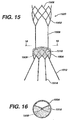
- FIG. 15 illustrates an alternate exemplary supra-renal anchoring stent gasket 1500.
- the supra-renal anchoring stent gasket 1500 comprises an anchoring portion 1502 and a sealing and anchoring portion 1504.
- the anchoring portion anchors the stent gasket 1500 in healthy tissue above cross-arteries, for example, the renal arteries.
- the sealing and anchoring portion 1504 seals and anchors the second prostheses, described in detail below.
- the anchoring portion 1502 and the sealing and anchoring portion 1504 are connected by a plurality of struts or bridges 1506 and both portions comprise a plurality of struts 1508 which may be interconnected in any number of suitable geometric patterns such as diamonds.
- struts forming the geometric pattern may be deformed out of the circumferential plane towards the centre of the lumen to create flaps.
- the sealing and anchoring portion 1504 is covered with a sealing material or gasket 1510 which serves as a sealing means for the second prostheses.
- These flaps act similarly to the stitching illustrated in Figures 14a-c .
- the supra-renal anchoring stent gasket comprises recapture legs 1512 with flanges 1514 as described above.
- the second prosthesis is a bypass conduit or the like that is typically deployed in an arterial passageway upstream of an aneurysm, and establishes a fluid flow path through the system or a portion thereof.
- the second prosthesis defines a fluid flow path that passes through the arterial segment having the aneurysm, e.g., bypassing the aneurysm.
- the second prosthesis extends from a healthy portion of the artery, through the arterial segment having the aneurysm, and into another healthy portion of the artery or another artery.
- the second prosthesis defines a fluid flow path from one portion of the system, e.g., a proximal portion or end, to another portion, e.g., a distal portion or end, or an intermediate portion.
- the second prosthesis functions to bypass the aneurysm, and to properly position and/or anchor the distal end of the system in an artery.
- the second prosthesis may also include one or more structures for positioning and anchoring the second prosthesis in the artery or in the first prosthesis.
- the second prosthesis is adapted to engage the first prosthesis.
- One or more markers may be optionally disposed in or on the stent between the proximal end and the distal end.
- two or more markers are sized and/or positioned to identify a location on the prosthesis, or to identify the position of the prosthesis, or a portion thereof, in relation to an anatomical feature or another system component.
- fluoroscopically identifiable sutures or staples are used; these sutures or staples may also attach the graft material to the stent.
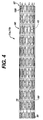
- FIGS 1 , 4 , 8 , 9 show exemplary second or bypass prostheses 11a, 11b of the present invention.
- Second prosthesis 11a, 11b includes a substantially cylindrical self-expanding lattice, support, or stent 40, typically made from a plurality of interconnected struts 44.
- Lattice 40 defines an interior space having two open ends, a proximal end 41 and a distal end 42.
- the interior and/or exterior surfaces of lattice 40 may be covered by or support at least one graft material 60.
- the second prosthesis typically includes a support matrix or stent that supports a graft material.
- One end of the second prosthesis is typically adapted to engage one or more portions of a first prosthesis.
- the proximal end of second prosthesis is adapted to matingly engage a proximal portion of the first prosthesis.
- the second prosthesis may optionally include at least one attachment structure on its distal end for engaging and securing the prosthesis in a portion of an artery downstream of the aneurysm.
- any of the stents of the present invention form a support or lattice structure suitable for supporting a graft material.
- the stent defines a channel through which a fluid, such as blood, may flow.
- a typical stent comprises an expandable lattice or network of interconnected struts.
- the lattice is laser cut from an integral tube of material.
- the diamond pattern for the anchors, as well as the other hoops, provide the hoops with radial and longitudinal stiffness.
- the longitudinal strength provides for better mechanical fixation of stent 40 to a graft material (described below).
- the radial strength provides the proximal hoop 45 with better attachment and sealing to the gasket material, and provides the distal hoop 46 with better fixation and sealing to the arterial wall. Further, the distal hoop may be flared, and may be exposed after the graft material has been attached to the stent.
- the proximal and distal hoops have greater radial and longitudinal strength than the hoops therebetween.
- the stiffer ends may be accomplished by changing the dimensions of the struts for the end hoops, or by varying the heat treatment of the end hoops during manufacture.
- the rings allow the stent to bend more easily, and generally provide for more flexibility when the stent is being delivered through a tortuous vessel.
- the strength of the diamond hoops scaffolds any graft folding into the blood flow lumen, while maintaining a tight kink radius.
- the proximal and/or distal end of a stent may include one or more anchors and/or one or more struts of the stent configured into an anchor.
- One or more anchors commonly referred to as recapture legs, may also be configured to releasably engage a delivery device, such as a catheter, or a portion thereof.
- the distal end of the stent is preferably configured to engage a complementary structure on a delivery device, such as a catheter or a portion thereof.
- the distal end of the stent may include one or more keys that engage, preferably releasably engage, a corresponding latch on the catheter.
- An exemplary configuration is shown in Figure 7 . It is intended that the invention should not be limited by the precise structures used to engage the stent to the delivery device.
- any of the stents of the present invention may be formed from any material suitable for functioning in vivo as a support for graft material.
- a stent of the present invention may be formed from a wide variety of materials, all of which are well known to those skilled in the art.
- the stent is formed from a metal or metal alloy.
- the stent is formed from superelastic Nickel Titanium alloys (Nitinol). Descriptions of medical devices which use such alloys can be found in US-4665906 and EP-A-928606 .
- a stent according to the present invention is preferably laser cut from a tubular piece of nitinol and thereafter treated so as to exhibit shape memory properties at body temperature.
- the stent material is expandable or collapsible, i.e., moveable from a first closed position to a second open position, or vice versa.
- pleats 61 help facilitate stent graft manufacture, in that they indicate the direction parallel to the longitudinal axis, allowing stent to graft attachment along these lines, and thereby inhibiting accidental twisting of the graft relative to the stent after attachment.
- the force required to push the stent-graft out of the delivery system may also be reduced, in that only the pleated edges of the graft make frictional contact with the inner surface of the delivery system.
- One further advantage of the pleats is that blood tends to coagulate generally uniformly in the troughs of the pleats, discouraging asymmetric or large clot formation on the graft surface, thereby reducing embolus risk.
- the graft material may also include one or more, and preferably a plurality of, radially oriented pleat interruptions 70.
- the pleat interruptions are typically substantially circular and are oriented perpendicular to longitudinal axis.
- Pleat interruptions 70 allow the graft and prosthesis to bend better at selective points. This design provides for a graft material that has good crimpability and improved kink resistance.
- the graft material may be impervious or substantially impervious to the flow of blood, or may be porous.
- a graft material is impervious if it prevents blood from passing through the graft material on contact with blood or after the graft material is saturated with blood.
- Choice of the flow characteristics of a graft material are well known to those skilled in the art, and are tied in part to the intended function of the prosthesis or portion of the prosthesis. For example, it may be desirable for the graft material that forms the cover of the first prosthesis to be impervious or substantially impervious to the flow of blood. Alternately, it may be desirable for a graft material to be porous or partially porous to promote biofusion.
- a graft material that limits or eliminates the amount of blood that passes between the graft and the arterial wall, to provide a catheter-delivered graft or prosthesis that extends through a longer portion of an artery, to improving the anchoring mechanisms between two prostheses, to improving the anchoring mechanism between the prosthesis and the arterial wall or an interluminal cavity within an artery, and to improve the fluid dynamic and performance characteristics if the implanted prosthesis.
- the number, location, and size of the markers may vary, and the markers may be used alone or in combination to identify the position of a particular portion of the prosthesis.
- a proximal marker adjacent aperture 32 may be five mm long and the proximal marker adjacent hole 33 may be two mm long.
- two distal markers may be one hundred eighty degrees apart, and a proximal marker may be positioned equidistant from each of the distal markers. In this exemplary configuration, the proximal marker then aids proper rotational positioning of the device.
- a method of using a device includes delivering and positioning a system or component of a system in a fluid conduit, such as an aorta.
- a fluid conduit such as an aorta.
- the components described above permit intraluminal delivery into an aorta. This is accomplished by percutaneously inserting the prostheses into the same or different arteries, e.g., a femoral artery, and navigating them to the site of the aneurysm. This type of procedure is similar to delivery of angioplasty catheters and guiding catheters into the human vasculature.
Abstract
Description
- The present invention relates to devices for repairing aneurysm, and more particularly, to percutaneously and/or intraluminally delivered devices for repairing aneurysms, such as abdominal aortic aneurysms and thoracic aortic aneurysms.
- An aneurysm is an abnormal dilation of a layer or layers of an arterial wall, usually caused by a systemic collagen synthetic or structural defect. An abdominal aortic aneurysm is an aneurysm in the abdominal portion of the aorta, usually located in or near one or both of the two iliac arteries or near the renal arteries. The aneurysm often arises in the infrarenal portion of the diseased aorta, for example, below the kidneys. A thoracic aortic aneurysm is an aneurysm in the thoracic portion of the aorta. When left untreated, the aneurysm may rupture, usually causing rapid fatal haemorrhaging.
- Aneurysms may be classified or typed by their position as well as by the number of aneurysms in a cluster. Typically, abdominal aortic aneurysms may be classified into five types. A Type I aneurysm is a single dilation located between the renal arteries and the iliac arteries. Typically, in a Type I aneurysm, the aorta is healthy between the renal arteries and the aneurysm and between the aneurysm and the iliac arteries.
- A Type II A aneurysm is a single dilation located between the renal arteries and the iliac arteries. In a Type II A aneurysm, the aorta is healthy between the renal arteries and the aneurysm, but not healthy between the aneurysm and the iliac arteries. In other words, the dilation extends to the aortic bifurcation. A Type II B aneurysm comprises three dilations. One dilation is located between the renal arteries and the iliac arteries. Like a Type II A aneurysm, the aorta is healthy between the aneurysm and the renal arteries, but not healthy between the aneurysm and the iliac arteries. The other two dilations are located in the iliac arteries between the aortic bifurcation and the bifurcations between the external iliacs and the internal iliacs. The iliac arteries are healthy between the iliac bifurcation and the aneurysms. A Type II C aneurysm also comprises three dilations. However, in a Type II C aneurysm, the dilations in the iliac arteries extend to the iliac bifurcation.
- A Type III aneurysm is a single dilation located between the renal arteries and the iliac arteries. In a Type III aneurysm, the aorta is not healthy between the renal arteries and the aneurysm. In other words, the dilation extends to the renal arteries.
- A ruptured abdominal aortic aneurysm is presently the thirteenth leading cause of death in the United States. The routine management of abdominal aortic aneurysms has been surgical bypass, with the placement of a graft in the involved or dilated segment. Although resection with a synthetic graft via transperitoneal or retroperitoneal procedure has been the standard treatment, it is associated with significant risk. For example, complications include perioperative myocardial ischemia, renal failure, erectile impotence, intestinal ischemia, infection, lower limb ischemia, spinal cord injury with paralysis, aorta-enteric fistula, and death. Surgical treatment of abdominal aortic aneurysms is associated with an overall mortality rate of five percent in asymptomatic patients, sixteen to nineteen percent in symptomatic patients, and is as high as fifty percent in patients with ruptured abdominal aortic aneurysms.
- Disadvantages associated with conventional surgery, in addition to the high mortality rate, include an extended recovery period associated with the large surgical incision and the opening of the abdominal cavity, difficulties in suturing the graft to the aorta, the loss of the existing thrombosis to support and reinforce the graft, the unsuitability of the surgery for many patients having abdominal aortic aneurysms, and the problems associated with performing the surgery on an emergency basis after the aneurysm has ruptured. Further, the typical recovery period is from one to two weeks in the hospital, and a convalescence period at home from two to three months or more, if complications ensue. Since many patients having abdominal aortic aneurysms have other chronic illnesses, such as heart, lung, liver and/or kidney disease, coupled with the fact that many of these patients are older, they are less than ideal candidates for surgery.
- The occurrence of aneurysms is not confined to the abdominal region. While abdominal aortic aneurysms are generally the most common, aneurysms in other regions of the aorta or one of its branches are possible. For example, aneurysms may occur in the thoracic aorta. As is the case with abdominal aortic aneurysms, the widely accepted approach to treating an aneurysm in the thoracic aorta is surgical repair, involving replacing the aneurysmal segment with a prosthetic device. This surgery, as described above, is a major undertaking, with associated high risks and with significant mortality and morbidity.
- Over the past five years, there has been a great deal of research directed at developing less invasive, endovascular, i.e. catheter directed, techniques for the treatment of aneurysms, specifically abdominal aortic aneurysms. This has been facilitated by the development of vascular stents, which can and have been used in conjunction with standard or thin-wall graft material in order to create a stent-graft or endograft. The potential advantages of less invasive treatments have included reduced surgical morbidity and mortality along with shorter hospital and intensive care unit stays.
- Stent-grafts or endoprostheses are now FDA approved and commercially available. Their delivery procedure typically involves advanced angiographic techniques performed through vascular accesses gained via surgical cutdown of a remote artery, which may include the common femoral or brachial arteries. Over a guidewire, the appropriate size introducer will be placed. The catheter and guidewire are passed through the aneurysm. Through the introducer, the stent-graft will be advanced to the appropriate position. Typical deployment of the stent-graft device requires withdrawal of an outer sheath while maintaining the position of the stent-graft with an inner-stabilizing device. Most stent-grafts are self-expanding; however, an additional angioplasty procedure, e.g., balloon angioplasty, may be required to secure the position of the stent-graft. Following the placement of the stent-graft, standard angiographic views may be obtained.
- Due to the large diameter of the above-described devices, typically greater than twenty French (3F=1 mm), arteriotomy closure typically requires open surgical repair. Some procedures may require additional surgical techniques, such as hypogastric artery embolization, vessel ligation, or surgical bypass, in order to adequately treat the aneurysm or to maintain flow to both lower extremities. Likewise, some procedures will require additional, advanced catheter directed techniques, such as angioplasty, stent placement, and embolization, in order to successfully exclude the aneurysm and efficiently manage leaks.
- While the above-described endoprostheses represent a significant improvement over conventional surgical techniques, there is a need to improve the endoprostheses, their method of use and their applicability to varied biological conditions. Accordingly, in order to provide a safe and effective alternate means for treating aneurysms, including abdominal aortic aneurysms and thoracic aortic aneurysms, a number of difficulties associated with currently known endoprostheses and their delivery systems must be overcome. One concern with the use of endoprostheses is the prevention of endo-leaks and the disruption of the normal fluid dynamics of the vasculature. Devices using any technology should preferably be simple to position and reposition as necessary, should preferably provide an acute fluid tight seal, and should preferably be anchored to prevent migration without interfering with normal blood flow in both the aneurysmal vessel as well as branching vessels. In addition, devices using the technology should preferably be able to be anchored, sealed, and maintained in bifurcated vessels, tortuous vessels, highly angulated vessels, partially diseased vessels, calcified vessels, odd shaped vessels, short vessels, and long vessels. In order to accomplish this, the endoprostheses should preferably be extendable and re-configurable while maintaining acute and long term fluid tight seals and anchoring positions.
- The endoprostheses should also preferably be able to be delivered percutaneously utilizing catheters, guidewires and other devices which substantially eliminate the need for open surgical intervention. Accordingly, the diameter of the endoprostheses in the catheter is an important factor. This is especially true for aneurysms in the larger vessels, such as the thoracic aorta.
- As will be recognized by those skilled in the art, placing a prosthesis upstream of an aneurysm requires a sufficient length of suitable artery within which to anchor an upstream portion of the prosthesis. For some patients, a suitable length of artery upstream of the aneurysm is not available. For example, a Schumacher Type III abdominal aortic aneurysm is typically characterized by a short infra-renal neck (i.e., the section of the artery downstream of the renal arteries and upstream of an aneurysm is typically less than about 15 mm) and/or a high angulated neck (greater than about 45). In both of these circumstances, it is typically not possible to implant a prosthesis upstream of the aneurysm without blocking one or both of the renal arteries. Also, the shape, angle, or length of the existing artery may prevent achieving a fluid tight connection between the prosthesis and the arterial wall.
-
EP-A-0947179 discusses a precursor stent. The stent comprises a first expandable member and a second expandable member connected to the first expandable member by struts. -
US-A-2001/0053930 discusses an aortic stent comprising cranial and caudal zones connected by an intermediate zone comprising multiple longitudinal struts already adress these type of aneurysms. - a need exists for a prosthesis specifically designed to accommodate a highly angulated section of artery.
- The suprarenal anchoring prosthesis of the present invention provides a means for overcoming the problems associated with anchoring and/or sealing a prosthesis in an artery that is highly angulated, too short for proper positioning and/or otherwise diseased as briefly described above.
- According to the present invention, there is provided a system for bypassing an aneurysm as defined in appended claim 1.
- A prosthesis according to the present invention is specifically adapted and configured for an unsuitable section of artery or the like upstream of an aneurysm.
- A system according to the present invention is intended for repairing or bypassing an aneurysm, preferably an aortic aneurysm. The system may also be used to direct fluid flow from one portion of a fluid pathway to another. The system may also be used for repairing or bypassing aneurysms having an upstream portion unsuitable for anchoring or using a typical prosthesis.
- A portion of the second matrix may or may not include graft material engaging the second matrix.
- The present invention also includes a first prosthesis adapted to engage or seat at least one second prosthesis, the first prosthesis comprising a stent; the stent comprising a first portion suitable for engaging a section of a first artery downstream of a junction between a first artery and a second artery; the stent comprising a second portion suitable for engaging an upstream portion of the first artery, the second portion being adapted to engage a section of the first artery upstream of the junction between the first and second arteries; the stent including elongated struts interconnecting the first portion with the second portion.
- An intermediate portion of the stent or prosthesis may be configured into a highly flexible bridge, pivot, joint, axis, juncture, hinge, hub or the like.
- In exemplary embodiments of the invention, any intermediate portion described above may be open, i.e., freely permits fluid cross flow, or is free of any graft material.
- Any of the prostheses or stents described above may form a component or portion of a system or kit for repairing or bypassing an aneurysm.
- The present invention is also directed to a system for repairing and/or replacing an aneurysm, said system being variously configured and/or assembled using components described in more detail below. Typical systems according to this aspect of the invention include one or more first prostheses or a sealing component, one or more second, or bypass, prostheses or a fluid flow component, and, optionally, one or more component receptacles, assemblies, or connectors for matingly engaging one component with another. Preferred embodiments of a system of the present invention include a second matrix configured to engage two fluid flow path components, or bypass prostheses.
- Any of the prostheses, stents, systems, or kits described above may be incorporated in a method for treating an aneurysm. The prostheses, stents, systems, or kits are used to treat an aortic aneurysm, even more preferably, an abdominal aortic aneurysm.
- A device according to the present invention may be used in a typical method for positioning which includes positioning a first portion of a stent or first prosthesis in a first section of an artery, positioning a second portion of the stent or first prosthesis in a second section of the artery, the second section being upstream of an aneurysm, and engaging at least one second prosthesis with the stent or first prosthesis, the second prosthesis forming a fluid flow path that bypasses the aneurysm. In preferred embodiments of the invention, the method includes anchoring the system using the second prosthesis in its expanded configuration. The method may further include anchoring the most upstream portion of the system using the first portion of the stent, matrix, or first prosthesis.
- Other embodiments of the invention will be evident from the description provided below.
- As used herein, aortic aneurysm refers to any failure of a conduit, such as an aortic wall, typically characterized by an undesirable dilation of a portion of the artery, vessel malformation, or an occlusion. The system and structures of the present invention may be used to treat, repair, replace, or bypass any blood vessel (e.g., artery, vein, capillary); any fluid carrying vessel (e.g., lymphatic vessels); any organ or portion thereof that includes a blood or fluid vessel; or any junction between blood vessels, between fluid vessels, and between organs and blood vessels. An exemplary use of a system of the present invention is to repair an aortic aneurysm , and the use of such term is not intended to limit the use of the structures or systems of the present invention to repair or replace other conduit failures. The prosthesis of the present invention may also be utilized in the thoracic aorta, and may be used to repair thoracic aneurysms or thoracic dissecting aneurysms. Accordingly, use of the term "aortic aneurysm" is intended to relate to and include other aneurysms, including but not limited to both abdominal aortic aneurysms and thoracic aneurysms.
- The system and structures may be used to treat, repair, replace, or bypass an abdominal aortic aneurysm.
- As used herein fluid pathway refers to any in vivo structure through which a biological fluid passes. A preferred fluid pathway is an artery. Fluid pathways include, but are not limited to channels formed by an artery, a vein, a capillary, lymph nodes and channels, and arteries, veins, and capillaries within an organ or organelle.
- As used herein fluid or biological fluid refers to any fluid produced by an animal, including a human. Exemplary biological fluids include but are not limited to blood, oxygenated blood, de-oxygenated blood, gastric fluids, amniotic fluid, spinal fluid, and lymph. The preferred fluid is blood or oxygenated blood.
- As used herein, conduit typically refers to any structure used to convey a biological fluid. The conduit may be formed of natural or synthetic materials or combinations thereof. Exemplary conduits include but are not limited to an artery, a vein, a capillary, lymph nodes and channels, and arteries, veins, capillaries within an organ or organelle, and a prosthesis or system according to the invention.
- As used herein, "biofusion" refers to the ability of cells, proteins, fibrin, and other biological molecules to incorporate into the pore structure of a material, such as a foam or gasket material, or a graft material. It is believed that this feature promotes a long term stable biological interface that cannot be separated about six weeks after implantation.
- The biofusion effect has many advantages. It has the potential to obviate late endo-leakage by preventing areas of non-organized clot from being displaced or recanalised. It is also believed that biofusion creates a connective tissue collar around the prosthesis that may prevent the aortic neck from dilating over time. Restricting neck dilation avoids leakage pathways and implant migration that can be caused by an insufficient fit with the aorta.
- As used herein, adapted for communication, communicating, or similar terms refer to any means, structures, or methods for establishing operational association between two elements of the system. Similarly, engaging, adapted to engage, or similar terms refer to means, structures, or methods for contacting a first component, structure, or portion thereof with a second component, structure, or portion thereof. Exemplary structures are shown in the Figures. Typically, all of these terms and phrases refer to at least one structure in or on a first component configured to engage a complementary structure in or on a second component, and the use of these inter-engaging features to link a first prosthesis or component with a second prosthesis or component. The engagement or communication may be matingly (e.g., permanent) and/or releasably (e.g., temporary). In preferred embodiments of the invention, communication or engagement may be fluid tight, substantially fluid tight, or fluid tight to an extent so as to not substantially compromise the intended function of the structure.
- For example, a connector may be adapted to receive or connect to a complementary connector on another prosthesis. As used herein, connector refers to any structure used to form a joint or to join itself to another component or portion thereof. These connectors or connections establish a fluid flow path through various elements of the apparatus, assembly, or system. The system is intended to establish at least one fluid flow path through a vessel, conduit, organ, or portions thereof. Typical connections include but are not limited to mating connections, such as Luer-type, screw-type, friction-type, or connectors that are bonded together.
- As used herein, distal is used in accordance with its ordinary dictionary definition, e.g., referring to a position farthest from the beginning; in human anatomy, this term is commonly equivalent to caudal or inferior. Proximal is used in accordance with its ordinary dictionary definition, e.g., referring to a position nearest the beginning; in human anatomy, this term is commonly equivalent to cranial or superior. The terms distal and proximal are intended to convey opposite ends or portions of a device, channel, element, or structure. In relation to a fluid flow path, distal will typically refer to a downstream location in the fluid flow path, and proximal will typically refer to an upstream location, unless otherwise specifically noted. Anatomically, distal generally refers to "away from the heart" and proximal generally refers to "toward the heart."
- A system for treating an aortic aneurysm according to the present invention typically includes a first prosthesis or precursor stent and at least one second, or bypass, prosthesis. The components of the system may be delivered intraluminally to the site of the aneurysm using a catheter or the like. One skilled in the art will therefore recognize that it is beneficial to deliver the components of the system in a closed or first position, and to deploy the component in its functional location by expanding the component into an open or second position.
- Jointed stent, as used herein, refers to any stent structure or configuration that permits one section of the stent to be angled in relation to another section. The angled configuration may be fixed or moveable, flexible or non-flexible, preferably to accommodate the angle of the artery in which the prosthesis is placed. An exemplary embodiment is shown in
Figure 11 . Although the angle may be any angle, the preferred stent and first prosthesis of the present invention is capable of achieving a greater than about a forty-five degree angle between the two sections. A flexible stent structure, wherein the flexibility is derived from the bridge and/or strut configuration itself, may provide sufficient flexibility and/or articulation to accommodate extreme angulations in an artery's shape. These various flexible stent structures are also included in the meaning of jointed stent. - Embodiments of the invention will now be described by way of example with reference to the accompanying drawings, in which:
-
Figure 1 is an elevation view of a fully deployed aortic repair system for infra-renal use. -
Figure 2 is a perspective view of a stent for a infra-renal first prosthesis, shown for clarity in an expanded state. -
Figure 3 is a perspective view of a infra-renal first prosthesis having a stent covered by a gasket material. -
Figure 4 is a side elevation of a second prosthesis having a stent covered by a graft material. -
Figure 5 is an elevation view of a fully deployed first infra-renal prosthesis and an exemplary delivery system. -
Figure 6 is an end view of the graft material illustrating the graft material in its unexpanded or crimped configuration, and in its fully expanded configuration. -
Figure 7 is a partial, exploded perspective view of the distal end of a second prosthesis of the present invention illustrating an anchoring and delivery system. -
Figure 8 is an elevation view of an exemplary embodiment of a fully deployed supra-renal aortic repair system configured with a proximal extension anchor. -
Figure 9 is an elevation view of an exemplary embodiment of a fully deployed supra-renal aortic repair system of the present invention configured for use in a high angle fluid flow path. -
Figure 10 is a side elevation of an exemplary embodiment of a supra-renal stent having a proximal extension anchor. -
Figure 11 is a side elevation of an exemplary embodiment of a supra-renal stent of the present invention having an angled or jointed proximal extension anchor. -
Figures 12a to 12c show alternative exemplary embodiments of an angle junction for the stent ofFigure 11 . -
Figure 13 is a side cross section of a first infra-renal prosthesis according to the present invention. -
Figure 14a to 14c are a top view of alternate exemplary embodiments of a cover on a first infra-renal prosthesis according to the present invention. -
Figure 15 is a front elevational view of an alternate supra-renal anchoring device. -
Figure 16 is a top sectional view of the supra-renal anchoring device ofFigure 15 taken along section line 16-16. - An infra-renal and supra-renal system may include one or more prostheses. Exemplary infra-renal and supra-renal systems are shown in
Figures 1 and8 respectively. The system includes afirst prosthesis 10 and twosecond prostheses aneurysm 100. A proximal portion of the system may be positioned in asection 101 of an artery upstream of theaneurysm 100, and a distal portion of the system may be positioned in adownstream section 102 of the artery or a different artery. - As shown most clearly in
Figure 9 , the system of the present invention is intended for use whensection 101 of the artery is unsuitable for anchoring a portion of the system. As noted above, these circumstances exist when the length ofsection 101 is diseased, too short, includes a junction with asecond artery 103, and/or includes one or moreangled sections 104 of artery. - Under these and other circumstances, it may be desirable to provide a system, first prosthesis, or stent having a proximal portion that extends into an
upstream portion 105 of the artery. This proximal portion anchors the system or prosthesis in a section of the artery that is suitable for engaging and anchoring the system or prosthesis. - A prosthesis of the present invention includes a support, stent, or lattice of interconnected struts defining an interior space having an open proximal end and an open distal end. The lattice also defines an interior surface and an exterior surface. The interior and/or exterior surfaces of the lattice, or a portion of the lattice, may be covered by or support at least one covering material, such as a foam or graft material.
- As noted in more detail below in relation to specific system components, some prostheses of the present invention may be configured to seal and/or anchor the system in place, and/or to receive and position other prostheses. Typically these prostheses do not themselves define a fluid flow path. Other prostheses may be configured to define at least one fluid flow path. Typically, these prostheses define a channel or the like through which fluid, such as blood, flows. This channel or fluid flow path typically begins upstream of, or in an upstream portion of, a component of the system. The fluid flow path bypasses the aneurysm.
- A prosthesis may be moveable between an expanded or inflated position and an unexpanded or deflated position, and any position therebetween. This feature is shown in
Figure 6 . It may be desirable to provide a prosthesis that moves only from fully collapsed to fully expanded. It may be desirable to expand the prosthesis, then collapse or partially collapse the prosthesis. Such capability is beneficial to the surgeon to properly position or re-position the prosthesis. The prosthesis may be self-expanding, or may be expandable using an inflatable device, such as a balloon or the like. A delivery apparatus may be provided for a self-expanding prosthesis. The apparatus includes an outer sheath, comprising an elongated tubular member having distal and proximal ends, and an inner shaft located coaxially within the outer sheath, the shaft having a distal end and a proximal end. The distal end of the shaft further including at least two grooves disposed thereon. The flanges of the first prosthesis are configured to releasably engage the grooves of a portion of the delivery device. - An exemplary embodiment of infra and supra-renal systems for treating an abdominal aortic aneurysm according to the present invention is shown in
Figure 9 . For the purpose of the infra-renal embodiment, the system is deployed in theinfrarenal neck 101 of the abdominal aorta, upstream of where the artery splits into right and left common iliac arteries (also known as first and second iliac arteries).Figure 1 shows astent gasket 10 positioned in theinfrarenal neck 101; two prostheses, 11a and 11b, the proximal ends of which matingly engage aproximal portion 14 ofstent gasket 10, and the distal ends of which extend into aniliac artery 1 or 2. As illustrated, the body of the prosthesis forms a conduit or fluid flow path that passes through the location of theaneurysm 100. The components of the system define a fluid flow path that bypasses the section of the artery where the aneurysm is located. In the supra-renal systems, an anchoring portion may be positioned in healthy tissue above cross-arteries and a sealing portion below the cross-arteries as illustrated inFigure 9 . - These and other features of the prosthetic devices and systems of the present invention will be described in more detail below.
- The first prosthesis includes a support matrix or stent that supports a sealing material or foam, at least a portion of which is positioned across a biological fluid flow path, e.g., across a blood flow path. In some exemplary preferred embodiments of the invention, the first prosthesis, the stent, and the sealing material are radially expandable, and define a hollow space between a proximal portion of the prosthesis and a distal portion of the prosthesis. The first prosthesis may also include one or more structures for positioning and anchoring the prosthesis in the artery, and one or more structures for engaging and fixing at least one second prosthesis in place, e.g., a bypass prosthesis.
- The support matrix or stent of the first prosthesis may be formed from a wide variety of materials, may be configured in a wide variety of shapes, and their shapes and uses are well known in the art. Exemplary prior art stents are disclosed in
US-4733665 (Palmaz ),US-4739762 (Palmaz ) andUS-4776337 (Palmaz ). - In preferred embodiments of the invention, the stent of the first prosthesis is a collapsible, flexible, and self-expanding lattice or matrix formed from a metal or metal alloy, such as nitinol or stainless steel. Structures formed from stainless steel may be made self-expanding by configuring the stainless steel in a predetermined manner, for example, by twisting it into a braided configuration. More preferably, the stent is a tubular frame that supports a sealing material. The term tubular, as used herein, refers to any shape having a sidewall or sidewalls defining a hollow space or lumen extending therebetween; the shape may be generally cylindrical, elliptic, oval, rectangular, triangular, or any other shape. Furthermore, the shape may change or be deformable as a consequence of various forces that may press against the stent or prosthesis.
- The sealing material or gasket member supported by the stent may be formed of a wide variety of materials, may be configured in a wide variety of shapes, and their shapes and uses are well known in the art. Exemplary materials for use with this aspect of the invention are disclosed in
US-4739762 (Palmaz ) andUS-4776337 (Palmaz ). - The sealing material or gasket member may comprise any suitable material. Exemplary materials are composed of a biodurable and biocompatible material, including but are not limited to, open cell foam materials and closed cell foam materials. Exemplary materials include polyurethane, polyethylene, polytetrafluroethylene; and other various polymer materials, preferably woven or knitted, that provide a flexible structure, such as a polyester (such as that sold under the trade mark Dacron). Highly compressible foams are particularly preferred, preferably to keep the crimped profile low for better delivery. The sealing material or foam is preferably substantially impervious to blood when in a compressed state.
- The sealing material may cover one or more surfaces of the stent i.e., may be located along an interior or exterior wall, or both, and preferably extends across the proximal end or a proximal portion of the stent. The sealing material helps impede any blood trying to flow around the first prosthesis, e.g., between the first prosthesis and the arterial wall, and around one or more bypass prostheses after they have been deployed within the lumen of the first prosthesis (described in more detail below).
- In some exemplary embodiments of the invention, the sealing material stretches or covers a portion of the proximal end of the stent and along at least a portion of the outside wall of the stent.
- In some exemplary embodiments of the invention, it may be desirable for the portion of the sealing material covering the proximal portion of the stent to include one or more holes, apertures, points, slits, sleeves, flaps, weakened spots, guides, or the like for positioning a guidewire, for positioning a system component, such as a second prosthesis, and/or for engaging, preferably matingly engaging, one or more system components, such as a second prosthesis. For example, a sealing material configured as a cover or the like, and having a hole, may partially occlude the stent lumen.
- These openings may be variously configured, primarily to conform to its use. These structures promote proper side by side placement of one or more, preferably multiple, prostheses within the first prosthesis, and, in some exemplary embodiments of the invention, the sealing material may be configured or adapted to assist in maintaining a certain shape of the fully deployed system or component. Further, these openings may exist prior to deployment of the prosthesis, or may be formed in the prosthesis as part of a deployment procedure. The various functions of the openings will be evident from the description below. In exemplary embodiments of the invention, the sealing material is a foam cover that has a single hole.
- The sealing material may be attached to the stent by any of a variety of connectors, including a plurality of conventional sutures of polyvinylidene fluoride, polypropylene, polyester (such as that sold under the trade mark Dacron), or any other suitable material and attached thereto. Other methods of attaching the sealing material to the stent include adhesives, ultrasonic welding, mechanical interference fit and staples.
- One or more markers may be optionally disposed in or on the stent between the proximal end and the distal end. Preferably, two or more markers are sized and/or positioned to identify a location on the prosthesis, or to identify the position of the prosthesis, or a portion thereof, in relation to an anatomical feature or another system component.
- First prosthesis is typically deployed in an arterial passageway upstream of an aneurysm, and functions to open and/or expand the artery, to properly position and anchor the various components of the system, and, in combination with other components, seal the system or portions thereof from fluid leaks. For example, the sealing prosthesis may be deployed within the infrarenal neck, between an abdominal aortic aneurysm and the renal arteries of a patient, to assist in repairing an abdominal aortic aneurysm.
-
Figures 1 to 3 show an exemplary infra-renal sealing prosthesis 10 useful for understanding the present invention. Sealingprosthesis 10 includes a cylindrical or oval cross-sectional self-expanding lattice, support, orstent 12, typically made from a plurality ofinterconnected struts 13.Stent 12 defines an interior space orlumen 18 having two open ends, aproximal end 14 and adistal end 16. One or more markers may be optionally disposed in or on the stent between theproximal end 14 and thedistal end 16. -
Stent 12 may further include at least two, but preferably eight (as shown inFigure 2 ), spaced apartlongitudinal legs 20. Preferably, there is a leg extending from each apex 11 of diamonds formed bystruts 13. At least one leg, but preferably each leg, includes aflange 28 adjacent its distal end which, as is described in greater detail below, allows for the stent to be retrievable into its delivery apparatus after partial or nearly full deployment ofstent 12 so that it may be turned, or otherwise repositioned for proper alignment. -
Figure 3 shows the sealingmaterial 30 covering the proximal end ofstent gasket 10. In the exemplary embodiment shown inFigure 3 , sealingprosthesis 10 includes a sealingmaterial 30 having a first opening orhole 32 and a second opening or slit 33. - The gasket or sealing material covers at least a portion of the interior or exterior of the stent, and most preferably covers substantially all of the exterior of the stent. For example,
gasket material 30 may be configured to coverstent 12 from theproximal end 16 to thedistal end 14, but preferably not coveringlongitudinal legs 20. - The sealing material helps impede any blood trying to flow around
bypass prostheses Figure 1 ), and from flowing around the stent gasket itself. For this exemplary embodiment, sealingmaterial 30 is a compressible member or gasket located along the exterior of thestent 12 and at least a portion of the interior of thestent 12. - Exemplary embodiments of the invention are illustrated in
Figures 13 and14a to 14c. These Figures show afirst prosthesis 10 having agasket material 30 that covers at least a portion of the proximal end of thefirst prosthesis 10. Thegasket material 30 preferably includes a partition that extends approximately across the diameter of the cross section of thefirst prosthesis 10, wherein the partition includes a thicker gasket material, or further includes a foam or the like. The partition may be formed from any of the gasket or foam materials described above. - The exemplary embodiments illustrated in
Figures 13 and14 include athicker partition 71 in roughly an hourglass shape, although other shapes and sizes may be used. The partition defines at least one section 72 within the prosthesis having less material or the like, these sections being configured for receiving a proximal end of a second prosthesis, as is described in more detail below. In the exemplary embodiments shown inFigures 14 (a-c),partition 71 defines afirst section 72a and asecond section 72b;first section 72a is configured to receive a firstsecond prosthesis 11a, andsecond section 72b is configured to receive asecond prosthesis 11b, as described below. - It may be desirable to include one or more fibres, threads, filaments, straps, or the like for further defining a section 72. In the description below, the word fibre will be used as a shorthand descriptor for the element that includes fibres, threads, filaments, straps, or the like. In preferred embodiments of the invention, the fibre, etc., assists in positioning a
second prosthesis 11a or b. - The fibre or thread may be formed from any material and/or comprise any construction suitable for use in a biological environment, e.g., suitable for use in a blood vessel. The fibre may be woven or non-woven, formed of a synthetic or natural material, and/or single or multi-filament. Exemplary materials for forming the fibre or thread include but are not limited to polyester, polyester (such as that sold under the trade mark Dacron), polytetrafluoroethylene (such as that sold under the trade mark Teflon), polyurethane, porous polyurethane, expanded polyurethane, silicone, polyethylene terephthalate, and expanded polytetrafluoroethylene (ePTFE). The fibre or thread may also take on other forms. For example, the fibre or thread may be formed from glues or adhesives, or by melting sections of the gasket material. In addition, the fibre or thread may comprise struts deformed out of the circumferential plane.
- The end or ends of the fibre may be unattached or attached. In a preferred embodiment of the invention, both ends of the fibre are attached or fixed. For example, the ends may be sewn or fixed to the
cover 31. In a preferred embodiment of the invention, the ends of the fibre are fixed to astrut 13, even more preferably to a proximal portion ofstent 12. One or more ends of the fibre may be fixed to thestent 12 or thestrut 13 by threading, knotting, sewing, with adhesives, or any other mechanism for fixing the end of the fibre in place. - In the exemplary embodiments of the invention illustrated in
Figures 14a to 14c , fibre 73 may be variously configured. InFigure 14a ,fibres cover 31, and define or formfirst section 72a and asecond section 72b, as noted above. As shown, the ends of the fibres may be fixed to a strut; see 74a, 74b, 74c, and 74d. InFigure 14b , asingle fibre 73c may be positioned across the diameter of thecover 31, and is fixed to a strut at 74e and 74f. InFigure 14c , one or more crossedfibres partitions stent 12 at 74a, 74b, 74c, and 74d. - In some exemplary embodiments it may be desirable to use a fibre that is frangible or breakable. In these exemplary embodiments of the invention, the fibre breaks as the unexpanded prosthesis is expanded to its fully deployed position. Alternately, the ends of the fibres may be releasably fixed to the stent or strut when the prosthesis is in a collapsed condition, with one or more ends releasing as the prosthesis expands to its fully deployed position.
- These structures promote proper side by side placement of one or more, preferably multiple, prostheses within the
first prosthesis 10. -
Figures 8 ,9 ,10 and11 show alternative configurations of astent 10 intended for use with arterial sections unsuitable for use with a typical stent, such as that shown inFigure 2 . These stents are utilized for supra-renal anchoring. The stent configurations shown inFigures 8 ,9 ,10 and11 include a first portion ormatrix 12 configured to engage a downstream portion of an artery 101 (upstream of an aneurysm), and a second portion ormatrix 106 configured to engage an upstream portion of theartery 302. In arterial networks that are configured the same as or similar to the abdominal aorta network illustrated inFigure 8 ,matrix 106 may be configured to engage a portion of theartery 302 upstream of a second artery, such as arenal artery 103. - In these examples, of which
Figures 9 and11 are embodiments according to the invention, thestruts 13 ofmatrix 12 include aproximally extending bridge 107 comprising at least oneelongated strut 108 that communicates with or connects to thematrix 106. The exemplary embodiment of the invention shown inFigure 10 includes a plurality ofstruts 108, for example, eight, that in combination form a straight bridge. The exemplary embodiment of the invention shown inFigure 11 includes a plurality ofstruts 108, for example, eight, that in combination form a jointed bridge, described in more detail below. - In accordance with the present invention, the upstream portion, component, or prosthesis of the system may be variously configured to achieve a highly flexible structure suitable for accommodating one or more highly angled sections of an artery. In exemplary embodiments of the invention, the flexibility is achieved without creating kinks in the structure. In addition to the exemplary configurations shown in
Figures 8 ,9 ,10 ,11 ,12a-c , the upstream portion, component, or prosthesis of the system may include open or unattached diamonds or struts, resilient struts, or the like as explained in detail subsequently. In certain exemplary embodiments of the invention, the stent or matrix configuration is flexible both longitudinally and radially. As used herein, longitudinal flexibility refers to the ability for a stent or matrix to shorten or elongate as needed. - In the exemplary embodiments of the invention that include a stent configured as those shown in
Figures 9 and11 ,gasket material 30 preferably engages only thefirst portion 12 ofstent 10. Alternately,gasket material 30 may also engagesecond portion 106 ofstent 10. In the certain exemplary embodiments of the invention,bridge 107 is open or allows fluid cross flow, as is depicted by the arrows inFigures 8-11 . In these exemplary embodiments of the invention,gasket material 30 does not engagebridge 107, or the amount of gasket material that engagesbridge 107 does not prevent fluid cross flow. In other exemplary embodiments of the invention (not shown),gasket material 30 engages or coversbridge 107, but in this exemplary embodiment of the invention, the section ofgasket material 30 that engagesbridge 107 is porous, even more preferably, highly porous. It is intended that these various configurations of the stent and gasket material should not impede or substantially impede the flow of blood through the first prosthesis and intoarteries 103. - As noted above, the bridge section interposed between the
first matrix 12 and thesecond matrix 106 may be configured to accommodate a bend or highly angulated portion of an artery. In accordance with the present invention,bridge section 107 may be variously configured to allow a prosthesis to have an angled or flexible conformation. One skilled in the art will readily recognize that the need for a prosthesis having an angled conformation may be dependent on a number of factors, including but not limited to, the specific pathological condition of the patient, the flexibility of a given prosthesis, stent, or assembly, and the purpose for which the prosthesis is being used, among others. - In accordance with the present invention,
first matrix 12 andsecond matrix 106 may comprise similar or the same structures or elements. In some exemplary embodiments of the invention,second matrix 106 may be configured to achieve a greater outwardly radial force to anchor the system against or within the artery. In these exemplary embodiments of the invention, thefirst matrix 12 may not need to achieve a similar outwardly radial force since this section may receive one or more second prostheses which provide, when expanded or deployed, sufficient outwardly radial force to anchor the system in the artery. - One skilled in the art will recognize that a pathological or biological condition having a fluid flow path from a slight deflection to a wide angle (e.g., from about forty-five degrees to about ninety degrees) may warrant the use of a prosthesis according to the invention, having a structural configuration or element that allows the prosthesis to achieve the angled configuration. In these situations, it is believed that the following are exemplary embodiments of the invention that would provide beneficial results in achieving a fluid flow path through a tortuous channel.
- A prosthesis having an angled configuration may be achieved by interposing one or more flexible struts, flexible diamonds, open diamonds, pivots, joints, axes, junctions, hinges, narrows, hubs, or the like, in the
struts 108 or thebridge 107 betweenmatrix 12 andmatrix 106. Individual struts 108 may be joined or connected at this joint, as is shown inFigures 11 ,12a, and 12b , in various configurations that allow a prosthesis or stent to achieve an angled configuration. - In some exemplary embodiments of the invention, an intermediate section of the
bridge 107 includes apivot 120 or hinge.Pivot 120 inFigure 12c , and similar configurations, allow some degree of movement between the struts of the bridge, i.e., the angles between adjacent struts are moveable or changeable. - The present invention also includes a prosthesis or stent having an intermediate section of the
bridge 107 that comprises a joint, junction, orhub 121 in which the struts are fixed together at the intermediate section as illustrated inFigure 12a . - The present invention also includes a prosthesis or stent having an intermediate section of the
bridge 107 that comprises a narrow orcorseted configuration 122 in which a portion of thestruts 108 are positioned in close proximity to a portion of another strut. The exemplary embodiment inFigure 12b shows an intermediate portion of the struts in close proximity to each other. -
Figure 15 illustrates an alternate exemplary supra-renalanchoring stent gasket 1500. In this exemplary embodiment, the supra-renalanchoring stent gasket 1500 comprises ananchoring portion 1502 and a sealing and anchoringportion 1504. The anchoring portion anchors thestent gasket 1500 in healthy tissue above cross-arteries, for example, the renal arteries. The sealing and anchoringportion 1504 seals and anchors the second prostheses, described in detail below. The anchoringportion 1502 and the sealing and anchoringportion 1504 are connected by a plurality of struts orbridges 1506 and both portions comprise a plurality ofstruts 1508 which may be interconnected in any number of suitable geometric patterns such as diamonds. As illustrated inFigure 16 , struts forming the geometric pattern may be deformed out of the circumferential plane towards the centre of the lumen to create flaps. The sealing and anchoringportion 1504 is covered with a sealing material orgasket 1510 which serves as a sealing means for the second prostheses. These flaps act similarly to the stitching illustrated inFigures 14a-c . As in the other designs, the supra-renal anchoring stent gasket comprises recapturelegs 1512 withflanges 1514 as described above. - The second prosthesis is a bypass conduit or the like that is typically deployed in an arterial passageway upstream of an aneurysm, and establishes a fluid flow path through the system or a portion thereof. In some embodiments of the invention, the second prosthesis defines a fluid flow path that passes through the arterial segment having the aneurysm, e.g., bypassing the aneurysm. In these embodiments of the invention, the second prosthesis extends from a healthy portion of the artery, through the arterial segment having the aneurysm, and into another healthy portion of the artery or another artery. In some embodiments of the invention, the second prosthesis defines a fluid flow path from one portion of the system, e.g., a proximal portion or end, to another portion, e.g., a distal portion or end, or an intermediate portion.
- The second prosthesis functions to bypass the aneurysm, and to properly position and/or anchor the distal end of the system in an artery. The second prosthesis may also include one or more structures for positioning and anchoring the second prosthesis in the artery or in the first prosthesis. In one exemplary embodiment of the invention, the second prosthesis is adapted to engage the first prosthesis.
- One or more markers may be optionally disposed in or on the stent between the proximal end and the distal end. Preferably, two or more markers are sized and/or positioned to identify a location on the prosthesis, or to identify the position of the prosthesis, or a portion thereof, in relation to an anatomical feature or another system component. In preferred embodiments of the invention, fluoroscopically identifiable sutures or staples are used; these sutures or staples may also attach the graft material to the stent.
-
Figures 1 ,4 ,8 ,9 show exemplary second orbypass prostheses Second prosthesis stent 40, typically made from a plurality of interconnected struts 44.Lattice 40 defines an interior space having two open ends, a proximal end 41 and a distal end 42. The interior and/or exterior surfaces oflattice 40 may be covered by or support at least onegraft material 60. - The second prosthesis typically includes a support matrix or stent that supports a graft material. One end of the second prosthesis is typically adapted to engage one or more portions of a first prosthesis. In preferred embodiments of the invention, the proximal end of second prosthesis is adapted to matingly engage a proximal portion of the first prosthesis. The second prosthesis may optionally include at least one attachment structure on its distal end for engaging and securing the prosthesis in a portion of an artery downstream of the aneurysm. These and other features of the second prosthesis will be described in more detail below.
- Any of the stents of the present invention form a support or lattice structure suitable for supporting a graft material. In preferred embodiments of the invention, the stent defines a channel through which a fluid, such as blood, may flow. A typical stent comprises an expandable lattice or network of interconnected struts. In preferred embodiments of the invention, the lattice is laser cut from an integral tube of material.
- In accordance with the present invention, the stent may be variously configured. For example, the stent may be configured with struts or the like that form repeating geometric shapes. One skilled in the art will readily recognize that a stent may be configured or adapted to include certain features and/or to perform a certain function(s), and that alternate designs may be used to promote that feature or function.
- In some exemplary embodiments of the invention, the struts of the stent gasket form a matrix having diamond shapes. In the exemplary embodiment of the invention shown in
Figure 2 , the matrix or struts ofstent 10 is configured into a diamond shapes, preferably having approximately eight diamonds. In a most preferred embodiment of the invention, the fully expanded diamond pattern of a first prosthesis has angles of about forty-five to fifty-five degrees at their distal and proximal ends. In the exemplary embodiment of the invention shown inFigure 4 , the matrix or struts ofstent 40 may be configured into at least two hoops 43, each hoop 43 comprising a number of struts 44 having a diamond shape, having approximately nine diamonds. A second prosthesis, such assecond prosthesis 40, may further include a zigzag shapedring 50 for connecting adjacent hoops to one another. The zigzag shaped rings may be formed from a number of alternating struts 52, wherein each ring has fifty-four struts. - The diamond pattern for the anchors, as well as the other hoops, provide the hoops with radial and longitudinal stiffness. The longitudinal strength provides for better mechanical fixation of
stent 40 to a graft material (described below). The radial strength provides the proximal hoop 45 with better attachment and sealing to the gasket material, and provides thedistal hoop 46 with better fixation and sealing to the arterial wall. Further, the distal hoop may be flared, and may be exposed after the graft material has been attached to the stent. - In one preferred embodiment, the proximal and distal hoops have greater radial and longitudinal strength than the hoops therebetween. This creates a stent graft having stiff ends for anchoring, but a more flexible body for navigation through the vasculature. The stiffer ends may be accomplished by changing the dimensions of the struts for the end hoops, or by varying the heat treatment of the end hoops during manufacture. The rings allow the stent to bend more easily, and generally provide for more flexibility when the stent is being delivered through a tortuous vessel. When a non-compliant graft is attached to a stent, the strength of the diamond hoops scaffolds any graft folding into the blood flow lumen, while maintaining a tight kink radius.
- In accordance with some embodiments of the present invention, the proximal and/or distal end of a stent may include one or more anchors and/or one or more struts of the stent configured into an anchor. One or more anchors, commonly referred to as recapture legs, may also be configured to releasably engage a delivery device, such as a catheter, or a portion thereof. The distal end of the stent is preferably configured to engage a complementary structure on a delivery device, such as a catheter or a portion thereof. For example, the distal end of the stent may include one or more keys that engage, preferably releasably engage, a corresponding latch on the catheter. An exemplary configuration is shown in
Figure 7 . It is intended that the invention should not be limited by the precise structures used to engage the stent to the delivery device. - In the exemplary embodiments of the invention shown in
Figures 2 ,4 ,7 ,10 and11 , the stent may include one ormore anchors 46 configured to engage a corresponding structure on adelivery device 130. In accordance with the present invention, the delivery apparatus may include a collar having one or more grooves or the like adapted to releasably engage one or more complementary structures on a stent or prosthesis of the present invention. For example, the delivery apparatus shown inFigure 7 includes eightgrooves 144 to configure the delivery device to releasably engage both thefirst prosthesis 10 inFigure 1 (having eight anchors 46) and thesecond prosthesis 11a,b inFigure 7 (having three anchors 46). Such an anchor/delivery device configuration is particularly suited to partially deploying a prosthesis of the present invention, and to position or re-position the prosthesis. - Any of the stents of the present invention may be formed from any material suitable for functioning in vivo as a support for graft material. A stent of the present invention may be formed from a wide variety of materials, all of which are well known to those skilled in the art. In some embodiments of the invention, the stent is formed from a metal or metal alloy. In preferred embodiments of the invention, the stent is formed from superelastic Nickel Titanium alloys (Nitinol). Descriptions of medical devices which use such alloys can be found in
US-4665906 andEP-A-928606 - An inner or outer surface of a stent of the present invention may be covered by or support a graft material.
Graft material 60 can be made from any number of materials known to those skilled in the art, including woven polyester, polyester (such as that sold under the trade mark Dacron), polytetrafluoroethylene (such as that sold under the trade mark Teflon), polyurethane, porous polyurethane, silicone, polyethylene terephthalate, expanded polytetrafluoroethylene (ePTFE) and blends of various materials. - In some embodiments of the invention, it may be desirable to incorporate a biodegradable, or degradable material, such as albumin, collagen or any type of collagen. A graft material that is biodegradable would erode or dissolve over time; however, it is believed that the eroding graft material may be replaced by one or more biofusion constituents, or alternately, a layer of endothelium may grow as the graft material erodes. It is further believed that these new layers of endothelium may provide a new, fluid impervious lining within the aneurysm.
- It is preferred that all of the foregoing materials be porous to allow for an intimal layer to form a biofusion structure or matrix.
- The graft material may be variously configured, preferably to achieve predetermined mechanical properties. For example, the graft material may incorporate a single or multiple weaving and/or pleating patterns, or may be pleated or unpleated. For example, the graft may be configured into a plain weave, a satin weave, include continuous longitudinal pleats, interrupted pleats, annular helical pleats, radially oriented pleats, or combinations thereof. Alternatively, the graft material may be knitted or braided. In the embodiments of the invention in which the graft material is pleated, the pleats may be continuous or discontinuous. Also, the pleats may be oriented longitudinally, circumferentially, or combinations thereof.
- As shown in
Figure 4 ,graft material 60 may include a plurality oflongitudinal pleats 61 extending along its surface, generally parallel to the longitudinal axis of the prosthesis. As shown inFigure 6 , the pleats allow the prosthesis to collapse around its centre, much as it would be when it is delivered into a patient. As illustrated, the pleats come together as a series of radially oriented regular folds that pack together efficiently. This provides a relatively low profile delivery system, and provides for a controlled and consistent deployment therefrom. It is believed that this configuration minimizes wrinkling and other geometric irregularities. Upon subsequent expansion, the prosthesis assumes its natural cylindrical shape, and the pleats or folds uniformly and symmetrically open. - In addition, pleats 61 help facilitate stent graft manufacture, in that they indicate the direction parallel to the longitudinal axis, allowing stent to graft attachment along these lines, and thereby inhibiting accidental twisting of the graft relative to the stent after attachment. The force required to push the stent-graft out of the delivery system may also be reduced, in that only the pleated edges of the graft make frictional contact with the inner surface of the delivery system. One further advantage of the pleats is that blood tends to coagulate generally uniformly in the troughs of the pleats, discouraging asymmetric or large clot formation on the graft surface, thereby reducing embolus risk.
- As shown in
Figures 4 and9 , the graft material may also include one or more, and preferably a plurality of, radially orientedpleat interruptions 70. The pleat interruptions are typically substantially circular and are oriented perpendicular to longitudinal axis.Pleat interruptions 70 allow the graft and prosthesis to bend better at selective points. This design provides for a graft material that has good crimpability and improved kink resistance. - As noted above, the extension prosthesis may be pleated longitudinally, axially, or combinations of both. Under typical conditions, these pleats will form a relatively consistent pattern, e.g., pleats all of a certain length. In the exemplary embodiments of the present invention for use in a highly angulated artery, it may be desirable to vary the pattern or patterns of pleats. For example, in the area of greatest angle, it may be desirable to provide an extension prosthesis having one or two (or more, as needed) pleat interruptions or axially pleated sections separated by a shorter longitudinally pleated section or sections. It is believed that increasing the number of axial pleats in the highly angulated section of the artery reduces stress on the prosthesis, and may promote a more fluid tight fit of the system.
- The graft material as described above is preferably highly compressible, which also promotes a low crimped profile for better delivery characteristics.
- In accordance with the present invention, the graft material may be impervious or substantially impervious to the flow of blood, or may be porous. A graft material is impervious if it prevents blood from passing through the graft material on contact with blood or after the graft material is saturated with blood. Choice of the flow characteristics of a graft material are well known to those skilled in the art, and are tied in part to the intended function of the prosthesis or portion of the prosthesis. For example, it may be desirable for the graft material that forms the cover of the first prosthesis to be impervious or substantially impervious to the flow of blood. Alternately, it may be desirable for a graft material to be porous or partially porous to promote biofusion.
- In addition, it is preferable that the gasket member be substantially impervious to the flow of blood, at least when in a partially compressed state. When used throughout for the present invention, materials which are substantially impervious to the flow of blood include materials which become substantially impervious to the flow of blood after being saturated with blood.
- The foregoing graft materials may be knitted or woven, and may be warp or weft knitted. If the material is warp knitted, it may be provided with a velour, or towel like surface, which is believed to speed the formation of blood clots, thereby promoting the integration of a prosthesis or prosthesis component into the surrounding cellular structure.
- A graft material may be attached to a stent or to another graft material by any number of structures or methods known to those skilled in the art, including adhesives, such as polyurethane glue; a plurality of conventional sutures of polyvinylidene fluoride, polypropylene, polyester, or any other suitable material; ultrasonic welding; mechanical interference fit; and staples.
- As stated above, a stent preferably has a graft member attached thereto. The graft member covers at least a portion of the interior or exterior of the stent, and most preferably covers substantially all of the exterior of the stent. In some embodiments of the invention, prosthesis 1 1a,b includes
graft material 60 that covers only a portion of the distal end 42 ofmatrix 40. See, for example,Figure 4 . - In an alternate design, graft material may not be utilized on either end of the stent. For example, on any endolgegs, prosthesis, extension cuffs, stent gaskets or other covered stents, both ends thereof may be left uncovered. The biological body has the ability to cover the exposed portions of the stent with endothelial cells and thus these exposed portions become endothelialized or incorporated into the vessel wall. This may be an important factor in the long term stability of the system. Essentially, over long periods of time, the aneurysmal sac can and will shrink if it is totally excluded from blood flow. This shrinkage changes the morphology of the aortic region that has been treated with the bypass prosthesis. If all ends of the system are firmly anchored in the actual vessel, as is the case when the ends are covered with endothelium cells, the system will be better able to withstand these morphological changes.
- In accordance with the present invention, it may be highly desirable to provide a graft material that limits or eliminates the amount of blood that passes between the graft and the arterial wall, to provide a catheter-delivered graft or prosthesis that extends through a longer portion of an artery, to improving the anchoring mechanisms between two prostheses, to improving the anchoring mechanism between the prosthesis and the arterial wall or an interluminal cavity within an artery, and to improve the fluid dynamic and performance characteristics if the implanted prosthesis.
- As noted above, a stent and/or prosthesis of the present invention may include one or more markers. One skilled in the art will recognize that one or more markers may be positioned on the stent, the graft material, or on the prosthesis. In preferred embodiments of the invention, the markers are used to identify the position of the stent or prosthesis in relation to a body part and/or in relation to another stent or prosthesis, and/or to identify the position of one part of the prosthesis relative to another part. In most preferred embodiments of the invention, the marker(s) is used to identify a position in vivo.
- As shown in
Figures 2 and3 , a stent, such asstents 12 and/or 40 (Figure 4 ), preferably includes one or moreradiopaque markers 15. Exemplary materials for forming markers include but are not limited to tantalum, platinum, iridium, and gold. As shown,markers 15 are coils of radiopaque metal, wrapped around the struts of the stent.Markers 15 are preferably made from 0.19 mm (0.0075 inch) diameter tantalum (Ta) wire wrapped tightly around the struts. - The number, location, and size of the markers may vary, and the markers may be used alone or in combination to identify the position of a particular portion of the prosthesis. For example, a proximal marker
adjacent aperture 32 may be five mm long and the proximal markeradjacent hole 33 may be two mm long. Also, two distal markers may be one hundred eighty degrees apart, and a proximal marker may be positioned equidistant from each of the distal markers. In this exemplary configuration, the proximal marker then aids proper rotational positioning of the device. - Some exemplary embodiments of a prosthesis according to the present invention may include one or more connectors. In some embodiments of the invention, the connectors are used to engage or connect one prosthesis or component to another. In some embodiments of the invention, the connectors may be used to attach the gasket material or graft material to a stent or lattice.
- As noted above, one skilled in the art will recognize that a variety of materials and methodologies may be used to connect one prosthesis to another, or to attach the graft material to a stent. Exemplary connectors include but are not limited to sutures, staples, rivets, or the like. In preferred embodiments of the invention, the connector is a suture or staple, even more preferably, having a knotted or nub end. Further, a connector may be formed from a radiopaque material or a fluorescent material, each of which allow the connector to be used as a marker.
- In accordance with the present invention, it may be desirable to incorporate in a prosthesis a connector adapted for use with a lattice-like stent. A first connector 54, an exemplary embodiment of which is shown in
Figure 4 , may be configured for use at an end portion of a stent, preferably at an end portion of a strut 44. Asecond connector 56, an exemplary embodiment of which is shown inFigures 4 and7 , may be configured for use at an internal portion of a stent, preferably at the junction between two struts 44. - A connector configured for receiving a rivet, staple, suture, or the like, may include two apertures, each aperture configured to receive a leg of the rivet, staple, suture, or the like. In this embodiment of the invention, the end of each leg is preferably formed into a knot, nub or spherical end that is of larger diameter than the diameter of the aperture. Preferably, all of the elements noted above are assembled, the legs are passed through the apertures, and the end of each leg is formed into a nub. Alternatively, one end may be formed into a nub prior to placement through the aperture, with the second end being formed into a nub after assembly of all the elements.
- The number of connectors and staples are typically dictated by the size and structure of a particular stent; it is intended that the invention should not be limited thereby. The illustrated embodiments show six first connectors and three second connectors.
- The above staple aperture design or connector assembly has many advantages for attaching gasket material or a graft material to a stent. Because the legs of the staple are folded around and imbedded within a pocket or the like, any risk of puncturing an inflation balloon is minimized. In addition, the structural integrity of the prosthesis is increased because staples more securely attach the graft material to the stent, as compared to prior art designs which use suture or adhesives to attach the graft to the stent.
-
Staples 90 and 120 may be made from any number of materials known in the art, including tantalum alloys, platinum alloys or stainless steel, such as a grade of type 316 stainless steel. The staples may take on other configurations and shapes, and can be coated for lubricity purposes, wear resistance and for the prevention of corrosion. Essentially, the coating may be used for increased durability. The staples may be formed from a radiopaque material to identify the location of the staple, and to act as a marker to identify the location of a portion of the prosthesis. Using a different number of radiopaque staples on a distal end of a stent as compared to a proximal end further assists in identifying the position of the prosthesis. - A method of using a device according to the present invention includes delivering and positioning a system or component of a system in a fluid conduit, such as an aorta. The components described above permit intraluminal delivery into an aorta. This is accomplished by percutaneously inserting the prostheses into the same or different arteries, e.g., a femoral artery, and navigating them to the site of the aneurysm. This type of procedure is similar to delivery of angioplasty catheters and guiding catheters into the human vasculature. Upon proper positioning, the system components may be deployed either through a radially, outwardly extending force, e.g., expanding a balloon, or, if a self-expanding stent, by releasing the stent anchors from a constraint. Once fully deployed, at least one passageway is formed bypassing the aneurysm. As shown in
Figure 1 , it may be desirable to form two fluid flow paths bypassing the aneurysm, each fluid flow path extending into a separate downstream artery. - In preferred embodiments of the invention, the first prosthesis is a stent gasket, even more preferably, a stent gasket that expands automatically against the wall of the artery. As the stent gasket expands, proximal longitudinal legs allow the stent gasket diamond rings to expand, thereby anchoring the stent in place. The method also includes delivering and positioning at least one second prosthesis. In preferred embodiments of the invention, the second prosthesis is a bypass conduit for extending through an aneurysm. The second prosthesis is typically positioned within the first prosthesis, preferably into and through a hole in the first prosthesis cover. In most preferred embodiments of the invention, the hole is slightly smaller in diameter than the expanded diameter of the second prosthesis, thus sealingly engaging the second prosthesis in the first prosthesis. The sealed configuration of the second prosthesis within the first prosthesis forms a fluid pathway through the assembly or system, thereby bypassing the aneurysm.
-
Figures 9 generally shows how the system of the present invention may be deployed in vivo. One skilled in the art will readily recognize that a typical delivery device, such as a catheter, includes a guidewire or the like that passes through an aperture in the cover of the first prosthesis, and a collar or the like that releasably engages at least one anchor on the prosthesis. Once the anchors are released from the collar, the first prosthesis can expand, preferably automatically. The portion of the delivery device containing the collar can then be removed from the artery, typically leaving the guidewire in place, i.e., still positioned in an aperture of the first prosthesis cover. The guidewire can then be used to guide another prosthesis or prostheses into position. - In some embodiments of the invention, the collar of the delivery device, engaged to the prosthesis, may be positioned within a sheath or the like until the prosthesis is delivered. In preferred embodiments of the invention, a portion of the prosthesis may be partially deployed and/or positioned. Once it is determined that the prosthesis is in its proper position, the collar can be pushed out of the sheath, thereby releasing the anchors from the collar. If the prosthesis is a self-expanding prosthesis, release of the flanges will allow the prosthesis to deploy automatically. If the prosthesis is not self-expanding, a deflated balloon or the like may be delivered to the interior of the prosthesis using the guidewire. When the balloon is inflated, it will expand the prosthesis into its fully deployed position, i.e., fully expanded radially.
- As is evident to one skilled in the art, precisely placing a component(s) of the system may be critical. The physician must have precise placement of the components to ensure adequate repair of the aneurysm. The present invention allows the physician to fully deploy a component within the body without fully releasing the entire component from the delivery device. The anchors releasably interlock with complementary structures, such as grooves, on the delivery device, and, if the physician decides that the placement of the component is incorrect, the outer member of the delivery device may be moved relative to an inner member, thereby resulting in the prosthesis being retrieved or retracted within the delivery device. The extended legs and anchors allow the physician to temporarily position the prosthesis before full deployment. Once the physician is satisfied with a prosthesis' position, the
legs 20 may be released from their engagement with the delivery device. - In order to prevent the physician from prematurely completely deploying a prosthesis, a releasable stop may be preferably placed on the delivery device.
- In preferred embodiments of the invention, the system is used to bypass an abdominal aortic aneurysm (AAA). A method for treating or bypassing an AAA includes delivering, preferably percutaneously, a first prosthesis or precursor stent, or one of its components (e.g., the gasket member may be delivered separately, if desired). The components of the system are typically delivered through one of the femoral arteries and deployed within the infrarenal neck , between an abdominal aortic aneurysm and the renal arteries of a patient. Once the first prosthesis is properly positioned or re-positioned, the legs and anchors are fully released from the delivery device. The delivery device for the precursor stent may then be removed, without removing the guidewire, and another guidewire may be inserted through the other femoral artery and into first prosthesis. If the second guidewire is on the wrong side of the interior of first prosthesis, it will contact the occlusive member and be prevented from easily advancing. The physician may then properly reposition the guidewire through
hole 32. - Thereafter each delivery apparatus, each containing a sheathed second prosthesis, is inserted into femoral arteries and by sliding them over the guide wires; each of the two second prostheses are then positioned in the first prosthesis. Thereafter, the second prostheses may be either separately or simultaneously deployed.
- After proper delivery,
precursor stent 10 and prostheses 11(a) and 11(b) should appear as they do inFigures 1 ,8 , and9 .First prosthesis 10 along with its attachedgasket material 30 is firmly secured within an arterial section that includes theinfrarenal neck 101, and may or may not include a portion of the abdominal aorta upstream of the renal arteries. In a preferred embodiment of the invention, a proximal portion of the first prosthesis is positioned upstream of the renal arteries, a distal portion of the first prosthesis is positioned downstream of the renal arteries, for example, in the infrarenal neck region, and an intermediate portion of the first prosthesis is positioned across the junction between the renal arteries and the abdominal aorta. The outward force of thesecond prostheses 11a,b on theprecursor stent 10 helps to secure the device within the body. The distal ends of the second prosthesis may be firmly attached to theiliac arteries 1 and 2. Thereafter blood will flow from theabdominal aorta 302, through an exemplary system of the present invention comprising a first prosthesis and two second prostheses 11(a) and 11(b), and intoiliac arteries 1 and 2, thereby bypassing theaneurysm 100. - In accordance with the present invention, a system for bypassing an aneurysm may establish one, and possible multiple, fluid flow paths through the system. When the system is placed in an artery upstream of a junction with one or more other arteries, the system permits fluid, such as blood, to flow through the proximal end of the system, and a portion of the blood may flow out of the system into one of the cross arteries. Another portion of the fluid will continue within the system, bypassing the aneurysm and out of the system into one or more downstream arteries. A method of using the device of the present invention therefore includes establishing one or more fluid flow paths. In a preferred embodiment of the invention, the method includes establishing a first fluid flow path through the system, wherein the first fluid flow path bypasses the aneurysm. The method may further include establishing at least one second fluid flow path, wherein the second fluid flow path passes through a portion of the system, and passes out of an intermediate portion of the system into an artery or arteries.
- It is important to note that even though self-expanding stents are utilized, balloons may be utilized to over expand the stents for tacking them into position if necessary.
Claims (15)
- A system for bypassing an aneurysm comprising:a first prosthesis (10); andat least one bypass prosthesis (11a, 11b) communicating with the first prosthesis (10);wherein said first prosthesis (10) comprises a stent comprising a first matrix (12), a second matrix (106) and a plurality of longitudinally extending struts (108) connecting the first matrix (12) to the second matrix (106), wherein the first matrix (12) is configured to engage an unsuitable section of artery (101) upstream of an aneurysm, characterised in that the plurality of struts (108) include an intermediate section in which the plurality of longitudinally extending struts (108) are in closer proximity to each other than where they are connected to the first (12) and second (106) matrix.
- The system of claim 1 wherein said first matrix (12) is configured to receive at least one bypass prosthesis (11a, 11b).
- The system of claim 2 wherein a proximal portion of said first matrix (12) is configured to receive a proximal portion of said bypass prosthesis (11a, 11b).
- The system of claim 2 wherein said first matrix (12) is configured to receive two bypass prostheses (11a, 11b).
- The system of claim 1 wherein the plurality of struts (108) are configured to bridge a section of the artery unsuitable for anchoring the prosthesis (10).
- The system of claim 5 wherein a section of the artery unsuitable for anchoring the prosthesis comprises at least one of a short length of artery, and angulated artery, a section of artery containing a junction with another artery, and combinations thereof.
- The system of claim 1 further comprising a gasket material 30 configured to engage the first matrix (12).
- The system of claim 1 wherein the second matrix (106) is configured to anchor the prosthesis (10) in an artery.
- The system of claim 1 wherein the intermediate section comprises a joint.
- The system of claim 1 wherein the intermediate section comprises a hinge (120).
- The system of claim 1 wherein the intermediate section comprises an axis.
- The system of claim 1 wherein the intermediate section comprises a hub (121).
- The system of claim 1 wherein the intermediate section is configured to allow the first prosthesis to bend.
- The system of claim 1 wherein the intermediate section is configured into an angle.
- The system of claim 14 wherein the angle is greater than about 45 degrees.
Applications Claiming Priority (2)
| Application Number | Priority Date | Filing Date | Title |
|---|---|---|---|
| US10/041,116 US7326237B2 (en) | 2002-01-08 | 2002-01-08 | Supra-renal anchoring prosthesis |
| US41116 | 2002-01-08 |
Publications (3)
| Publication Number | Publication Date |
|---|---|
| EP1329204A2 EP1329204A2 (en) | 2003-07-23 |
| EP1329204A3 EP1329204A3 (en) | 2003-08-20 |
| EP1329204B1 true EP1329204B1 (en) | 2008-02-27 |
Family
ID=21914833
Family Applications (1)
| Application Number | Title | Priority Date | Filing Date |
|---|---|---|---|
| EP03250104A Expired - Lifetime EP1329204B1 (en) | 2002-01-08 | 2003-01-08 | Endoluminal vascular prosthesis |
Country Status (8)
| Country | Link |
|---|---|
| US (1) | US7326237B2 (en) |
| EP (1) | EP1329204B1 (en) |
| JP (1) | JP4350383B2 (en) |
| AT (1) | ATE387156T1 (en) |
| AU (1) | AU2002320656B2 (en) |
| CA (1) | CA2415735C (en) |
| DE (1) | DE60319290T2 (en) |
| MX (1) | MXPA03000267A (en) |
Families Citing this family (148)
| Publication number | Priority date | Publication date | Assignee | Title |
|---|---|---|---|---|
| US20060292206A1 (en) | 2001-11-26 | 2006-12-28 | Kim Steven W | Devices and methods for treatment of vascular aneurysms |
| US7029440B2 (en) * | 2002-03-13 | 2006-04-18 | Scimed Life Systems, Inc. | Distal protection filter and method of manufacture |
| US7756583B2 (en) | 2002-04-08 | 2010-07-13 | Ardian, Inc. | Methods and apparatus for intravascularly-induced neuromodulation |
| US8347891B2 (en) | 2002-04-08 | 2013-01-08 | Medtronic Ardian Luxembourg S.A.R.L. | Methods and apparatus for performing a non-continuous circumferential treatment of a body lumen |
| WO2004026183A2 (en) | 2002-09-20 | 2004-04-01 | Nellix, Inc. | Stent-graft with positioning anchor |
| US7481821B2 (en) | 2002-11-12 | 2009-01-27 | Thomas J. Fogarty | Embolization device and a method of using the same |
| US9125733B2 (en) | 2003-01-14 | 2015-09-08 | The Cleveland Clinic Foundation | Branched vessel endoluminal device |
| EP1583487B1 (en) * | 2003-01-14 | 2016-11-02 | The Cleveland Clinic Foundation | Branched vessel endoluminal device |
| US20040260382A1 (en) | 2003-02-12 | 2004-12-23 | Fogarty Thomas J. | Intravascular implants and methods of using the same |
| WO2004093746A1 (en) | 2003-03-26 | 2004-11-04 | The Foundry Inc. | Devices and methods for treatment of abdominal aortic aneurysm |
| US6945992B2 (en) * | 2003-04-22 | 2005-09-20 | Medtronic Vascular, Inc. | Single-piece crown stent |
| US20050033416A1 (en) * | 2003-05-02 | 2005-02-10 | Jacques Seguin | Vascular graft and deployment system |
| US20050015110A1 (en) | 2003-07-18 | 2005-01-20 | Fogarty Thomas J. | Embolization device and a method of using the same |
| US8721710B2 (en) * | 2003-08-11 | 2014-05-13 | Hdh Medical Ltd. | Anastomosis system and method |
| EP3045136B1 (en) | 2003-09-12 | 2021-02-24 | Vessix Vascular, Inc. | Selectable eccentric remodeling and/or ablation of atherosclerotic material |
| ATE440564T1 (en) * | 2003-10-10 | 2009-09-15 | Cleveland Clinic Foundation | ENDOLUMINAL PROSTHESIS WITH CONNECTABLE MODULES |
| US20050171597A1 (en) * | 2003-11-08 | 2005-08-04 | Boatman Scott E. | Helical stent for branched vessel prosthesis |
| US20050177224A1 (en) * | 2004-02-11 | 2005-08-11 | Fogarty Thomas J. | Vascular fixation device and method |
| DE602005025324D1 (en) | 2004-03-31 | 2011-01-27 | Cook Inc | STENT STORAGE DEVICE |
| US8048140B2 (en) * | 2004-03-31 | 2011-11-01 | Cook Medical Technologies Llc | Fenestrated intraluminal stent system |
| US8048145B2 (en) | 2004-07-22 | 2011-11-01 | Endologix, Inc. | Graft systems having filling structures supported by scaffolds and methods for their use |
| US9283099B2 (en) * | 2004-08-25 | 2016-03-15 | Advanced Cardiovascular Systems, Inc. | Stent-catheter assembly with a releasable connection for stent retention |
| US8920414B2 (en) | 2004-09-10 | 2014-12-30 | Vessix Vascular, Inc. | Tuned RF energy and electrical tissue characterization for selective treatment of target tissues |
| US8396548B2 (en) | 2008-11-14 | 2013-03-12 | Vessix Vascular, Inc. | Selective drug delivery in a lumen |
| US9713730B2 (en) | 2004-09-10 | 2017-07-25 | Boston Scientific Scimed, Inc. | Apparatus and method for treatment of in-stent restenosis |
| WO2006072835A2 (en) * | 2004-11-03 | 2006-07-13 | Jacques Seguin | Vascular graft and deployment system |
| US8048144B2 (en) * | 2004-11-30 | 2011-11-01 | Scimed Life Systems, Inc. | Prosthesis fixation device and method |
| WO2006079006A2 (en) * | 2005-01-21 | 2006-07-27 | Gen 4, Llc | Modular stent graft employing bifurcated graft and leg locking stent elements |
| WO2006113501A1 (en) | 2005-04-13 | 2006-10-26 | The Cleveland Clinic Foundation | Endoluminal prosthesis |
| US7666220B2 (en) | 2005-07-07 | 2010-02-23 | Nellix, Inc. | System and methods for endovascular aneurysm treatment |
| WO2007035619A1 (en) * | 2005-09-15 | 2007-03-29 | Cappella Inc. | Segmented ostial protection device |
| US20070150041A1 (en) * | 2005-12-22 | 2007-06-28 | Nellix, Inc. | Methods and systems for aneurysm treatment using filling structures |
| US8702785B2 (en) * | 2005-12-30 | 2014-04-22 | Cordis Corporation | Migration resistant prosthetic stent graft for treatment of abdominal aortic aneurysm |
| US8900287B2 (en) * | 2006-01-13 | 2014-12-02 | Aga Medical Corporation | Intravascular deliverable stent for reinforcement of abdominal aortic aneurysm |
| US8778008B2 (en) * | 2006-01-13 | 2014-07-15 | Aga Medical Corporation | Intravascular deliverable stent for reinforcement of vascular abnormalities |
| CN101484090B (en) * | 2006-04-19 | 2011-04-27 | 威廉A·库克澳大利亚有限公司 | Twin bifurcated stent graft |
| US8019435B2 (en) | 2006-05-02 | 2011-09-13 | Boston Scientific Scimed, Inc. | Control of arterial smooth muscle tone |
| AU2007258592B2 (en) | 2006-06-06 | 2012-10-25 | Cook Incorporated | Stent with a crush-resistant zone |
| EP2992850A1 (en) | 2006-10-18 | 2016-03-09 | Vessix Vascular, Inc. | Inducing desirable temperature effects on body tissue |
| EP2076194B1 (en) | 2006-10-18 | 2013-04-24 | Vessix Vascular, Inc. | System for inducing desirable temperature effects on body tissue |
| WO2009082654A1 (en) * | 2007-12-21 | 2009-07-02 | Cleveland Clinic Foundation | Prosthesis for implantation in aorta |
| AU2009240419A1 (en) | 2008-04-25 | 2009-10-29 | Nellix, Inc. | Stent graft delivery system |
| US20100305686A1 (en) * | 2008-05-15 | 2010-12-02 | Cragg Andrew H | Low-profile modular abdominal aortic aneurysm graft |
| US20090287145A1 (en) * | 2008-05-15 | 2009-11-19 | Altura Interventional, Inc. | Devices and methods for treatment of abdominal aortic aneurysms |
| CA2726596A1 (en) * | 2008-06-04 | 2009-12-10 | Nellix, Inc. | Sealing apparatus and methods of use |
| CA2743992A1 (en) | 2008-11-17 | 2010-05-20 | Minnow Medical, Inc. | Selective accumulation of energy with or without knowledge of tissue topography |
| US8858613B2 (en) | 2010-09-20 | 2014-10-14 | Altura Medical, Inc. | Stent graft delivery systems and associated methods |
| AU2010315417B2 (en) | 2009-10-28 | 2016-12-15 | Neograft Technologies, Inc. | Bioerodible wraps and uses therefor |
| US9572652B2 (en) * | 2009-12-01 | 2017-02-21 | Altura Medical, Inc. | Modular endograft devices and associated systems and methods |
| US20110276078A1 (en) | 2009-12-30 | 2011-11-10 | Nellix, Inc. | Filling structure for a graft system and methods of use |
| EP2519188A4 (en) | 2009-12-31 | 2017-03-22 | Neograft Technologies, Inc. | Graft devices and methods of fabrication |
| CN103068330B (en) | 2010-04-09 | 2016-06-29 | Vessix血管股份有限公司 | Power for treating tissue occurs and controls device |
| US9192790B2 (en) | 2010-04-14 | 2015-11-24 | Boston Scientific Scimed, Inc. | Focused ultrasonic renal denervation |
| US8473067B2 (en) | 2010-06-11 | 2013-06-25 | Boston Scientific Scimed, Inc. | Renal denervation and stimulation employing wireless vascular energy transfer arrangement |
| US10360817B2 (en) * | 2010-06-30 | 2019-07-23 | Stuart Charles Segall | Wearable partial task surgical simulator |
| US11688303B2 (en) | 2010-06-30 | 2023-06-27 | Strategic Operations, Inc. | Simulated torso for an open surgery simulator |
| US11854427B2 (en) | 2010-06-30 | 2023-12-26 | Strategic Operations, Inc. | Wearable medical trainer |
| US11495143B2 (en) | 2010-06-30 | 2022-11-08 | Strategic Operations, Inc. | Emergency casualty care trainer |
| WO2012012407A2 (en) | 2010-07-19 | 2012-01-26 | Neograft Technologies, Inc. | Graft devices and methods of use |
| US9408661B2 (en) | 2010-07-30 | 2016-08-09 | Patrick A. Haverkost | RF electrodes on multiple flexible wires for renal nerve ablation |
| US9358365B2 (en) | 2010-07-30 | 2016-06-07 | Boston Scientific Scimed, Inc. | Precision electrode movement control for renal nerve ablation |
| US9463062B2 (en) | 2010-07-30 | 2016-10-11 | Boston Scientific Scimed, Inc. | Cooled conductive balloon RF catheter for renal nerve ablation |
| US9155589B2 (en) | 2010-07-30 | 2015-10-13 | Boston Scientific Scimed, Inc. | Sequential activation RF electrode set for renal nerve ablation |
| US9084609B2 (en) | 2010-07-30 | 2015-07-21 | Boston Scientific Scime, Inc. | Spiral balloon catheter for renal nerve ablation |
| USD654170S1 (en) | 2010-09-20 | 2012-02-14 | St. Jude Medical, Inc. | Stent connections |
| USD652927S1 (en) | 2010-09-20 | 2012-01-24 | St. Jude Medical, Inc. | Surgical stent |
| USD654169S1 (en) | 2010-09-20 | 2012-02-14 | St. Jude Medical Inc. | Forked ends |
| USD684692S1 (en) | 2010-09-20 | 2013-06-18 | St. Jude Medical, Inc. | Forked ends |
| USD653342S1 (en) | 2010-09-20 | 2012-01-31 | St. Jude Medical, Inc. | Stent connections |
| USD653343S1 (en) * | 2010-09-20 | 2012-01-31 | St. Jude Medical, Inc. | Surgical cuff |
| USD652926S1 (en) | 2010-09-20 | 2012-01-24 | St. Jude Medical, Inc. | Forked end |
| USD653341S1 (en) | 2010-09-20 | 2012-01-31 | St. Jude Medical, Inc. | Surgical stent |
| USD648854S1 (en) | 2010-09-20 | 2011-11-15 | St. Jude Medical, Inc. | Commissure points |
| USD660433S1 (en) * | 2010-09-20 | 2012-05-22 | St. Jude Medical, Inc. | Surgical stent assembly |
| USD660432S1 (en) | 2010-09-20 | 2012-05-22 | St. Jude Medical, Inc. | Commissure point |
| USD660967S1 (en) | 2010-09-20 | 2012-05-29 | St. Jude Medical, Inc. | Surgical stent |
| US8974451B2 (en) | 2010-10-25 | 2015-03-10 | Boston Scientific Scimed, Inc. | Renal nerve ablation using conductive fluid jet and RF energy |
| US9220558B2 (en) | 2010-10-27 | 2015-12-29 | Boston Scientific Scimed, Inc. | RF renal denervation catheter with multiple independent electrodes |
| US9028485B2 (en) | 2010-11-15 | 2015-05-12 | Boston Scientific Scimed, Inc. | Self-expanding cooling electrode for renal nerve ablation |
| US9668811B2 (en) | 2010-11-16 | 2017-06-06 | Boston Scientific Scimed, Inc. | Minimally invasive access for renal nerve ablation |
| US9089350B2 (en) | 2010-11-16 | 2015-07-28 | Boston Scientific Scimed, Inc. | Renal denervation catheter with RF electrode and integral contrast dye injection arrangement |
| US9326751B2 (en) | 2010-11-17 | 2016-05-03 | Boston Scientific Scimed, Inc. | Catheter guidance of external energy for renal denervation |
| US9060761B2 (en) | 2010-11-18 | 2015-06-23 | Boston Scientific Scime, Inc. | Catheter-focused magnetic field induced renal nerve ablation |
| US9192435B2 (en) | 2010-11-22 | 2015-11-24 | Boston Scientific Scimed, Inc. | Renal denervation catheter with cooled RF electrode |
| US9023034B2 (en) | 2010-11-22 | 2015-05-05 | Boston Scientific Scimed, Inc. | Renal ablation electrode with force-activatable conduction apparatus |
| US20120157993A1 (en) | 2010-12-15 | 2012-06-21 | Jenson Mark L | Bipolar Off-Wall Electrode Device for Renal Nerve Ablation |
| US9220561B2 (en) | 2011-01-19 | 2015-12-29 | Boston Scientific Scimed, Inc. | Guide-compatible large-electrode catheter for renal nerve ablation with reduced arterial injury |
| US8801768B2 (en) | 2011-01-21 | 2014-08-12 | Endologix, Inc. | Graft systems having semi-permeable filling structures and methods for their use |
| WO2012139054A1 (en) | 2011-04-06 | 2012-10-11 | Endologix, Inc. | Method and system for endovascular aneurysm treatment |
| CA2832311A1 (en) | 2011-04-08 | 2012-11-29 | Covidien Lp | Iontophoresis drug delivery system and method for denervation of the renal sympathetic nerve and iontophoretic drug delivery |
| CN103930061B (en) | 2011-04-25 | 2016-09-14 | 美敦力阿迪安卢森堡有限责任公司 | Relevant low temperature sacculus for restricted conduit wall cryogenic ablation limits the device and method disposed |
| CN103813745B (en) | 2011-07-20 | 2016-06-29 | 波士顿科学西美德公司 | In order to visualize, be directed at and to melt transcutaneous device and the method for nerve |
| CN103813829B (en) | 2011-07-22 | 2016-05-18 | 波士顿科学西美德公司 | There is the neuromodulation system of the neuromodulation element that can be positioned in spiral guiding piece |
| WO2013055826A1 (en) | 2011-10-10 | 2013-04-18 | Boston Scientific Scimed, Inc. | Medical devices including ablation electrodes |
| US10085799B2 (en) | 2011-10-11 | 2018-10-02 | Boston Scientific Scimed, Inc. | Off-wall electrode device and methods for nerve modulation |
| US9420955B2 (en) | 2011-10-11 | 2016-08-23 | Boston Scientific Scimed, Inc. | Intravascular temperature monitoring system and method |
| US9364284B2 (en) | 2011-10-12 | 2016-06-14 | Boston Scientific Scimed, Inc. | Method of making an off-wall spacer cage |
| EP2768563B1 (en) | 2011-10-18 | 2016-11-09 | Boston Scientific Scimed, Inc. | Deflectable medical devices |
| EP2768568B1 (en) | 2011-10-18 | 2020-05-06 | Boston Scientific Scimed, Inc. | Integrated crossing balloon catheter |
| CN108095821B (en) | 2011-11-08 | 2021-05-25 | 波士顿科学西美德公司 | Orifice renal nerve ablation |
| US9119600B2 (en) | 2011-11-15 | 2015-09-01 | Boston Scientific Scimed, Inc. | Device and methods for renal nerve modulation monitoring |
| US9119632B2 (en) | 2011-11-21 | 2015-09-01 | Boston Scientific Scimed, Inc. | Deflectable renal nerve ablation catheter |
| US9265969B2 (en) | 2011-12-21 | 2016-02-23 | Cardiac Pacemakers, Inc. | Methods for modulating cell function |
| EP2793724B1 (en) | 2011-12-23 | 2016-10-12 | Vessix Vascular, Inc. | Apparatuses for remodeling tissue of or adjacent to a body passage |
| CN104135958B (en) | 2011-12-28 | 2017-05-03 | 波士顿科学西美德公司 | By the apparatus and method that have the new ablation catheter modulation nerve of polymer ablation |
| US9050106B2 (en) | 2011-12-29 | 2015-06-09 | Boston Scientific Scimed, Inc. | Off-wall electrode device and methods for nerve modulation |
| WO2013169927A1 (en) | 2012-05-08 | 2013-11-14 | Boston Scientific Scimed, Inc. | Renal nerve modulation devices |
| CA2881535A1 (en) | 2012-08-10 | 2014-02-13 | Altura Medical, Inc. | Stent delivery systems and associated methods |
| CN104540465A (en) | 2012-08-24 | 2015-04-22 | 波士顿科学西美德公司 | Intravascular catheter with a balloon comprising separate microporous regions |
| CN104780859B (en) | 2012-09-17 | 2017-07-25 | 波士顿科学西美德公司 | Self-positioning electrode system and method for renal regulation |
| US10549127B2 (en) | 2012-09-21 | 2020-02-04 | Boston Scientific Scimed, Inc. | Self-cooling ultrasound ablation catheter |
| WO2014047411A1 (en) | 2012-09-21 | 2014-03-27 | Boston Scientific Scimed, Inc. | System for nerve modulation and innocuous thermal gradient nerve block |
| US10835305B2 (en) | 2012-10-10 | 2020-11-17 | Boston Scientific Scimed, Inc. | Renal nerve modulation devices and methods |
| WO2014163987A1 (en) | 2013-03-11 | 2014-10-09 | Boston Scientific Scimed, Inc. | Medical devices for modulating nerves |
| US9693821B2 (en) | 2013-03-11 | 2017-07-04 | Boston Scientific Scimed, Inc. | Medical devices for modulating nerves |
| US9808311B2 (en) | 2013-03-13 | 2017-11-07 | Boston Scientific Scimed, Inc. | Deflectable medical devices |
| BR112015022688B1 (en) | 2013-03-14 | 2020-10-06 | Endologix, Inc. | METHOD FOR FORMING A MATERIAL IN SITU THROUGH INCREASING THE VOLUME OF AN EXPANDABLE MEMBER OF A MEDICAL DEVICE |
| JP6220044B2 (en) | 2013-03-15 | 2017-10-25 | ボストン サイエンティフィック サイムド,インコーポレイテッドBoston Scientific Scimed,Inc. | Medical device for renal nerve ablation |
| US9297845B2 (en) | 2013-03-15 | 2016-03-29 | Boston Scientific Scimed, Inc. | Medical devices and methods for treatment of hypertension that utilize impedance compensation |
| US10265122B2 (en) | 2013-03-15 | 2019-04-23 | Boston Scientific Scimed, Inc. | Nerve ablation devices and related methods of use |
| WO2014144809A1 (en) | 2013-03-15 | 2014-09-18 | Altura Medical, Inc. | Endograft device delivery systems and associated methods |
| US10022182B2 (en) | 2013-06-21 | 2018-07-17 | Boston Scientific Scimed, Inc. | Medical devices for renal nerve ablation having rotatable shafts |
| JP2016523147A (en) | 2013-06-21 | 2016-08-08 | ボストン サイエンティフィック サイムド,インコーポレイテッドBoston Scientific Scimed,Inc. | Renal denervation balloon catheter with a riding-type electrode support |
| US9707036B2 (en) | 2013-06-25 | 2017-07-18 | Boston Scientific Scimed, Inc. | Devices and methods for nerve modulation using localized indifferent electrodes |
| WO2015002787A1 (en) | 2013-07-01 | 2015-01-08 | Boston Scientific Scimed, Inc. | Medical devices for renal nerve ablation |
| EP3019105B1 (en) | 2013-07-11 | 2017-09-13 | Boston Scientific Scimed, Inc. | Devices for nerve modulation |
| US10413357B2 (en) | 2013-07-11 | 2019-09-17 | Boston Scientific Scimed, Inc. | Medical device with stretchable electrode assemblies |
| CN105682594B (en) | 2013-07-19 | 2018-06-22 | 波士顿科学国际有限公司 | Helical bipolar electrodes renal denervation dominates air bag |
| EP3024405A1 (en) | 2013-07-22 | 2016-06-01 | Boston Scientific Scimed, Inc. | Renal nerve ablation catheter having twist balloon |
| EP3024406B1 (en) | 2013-07-22 | 2019-06-19 | Boston Scientific Scimed, Inc. | Medical devices for renal nerve ablation |
| WO2015027096A1 (en) | 2013-08-22 | 2015-02-26 | Boston Scientific Scimed, Inc. | Flexible circuit having improved adhesion to a renal nerve modulation balloon |
| USD730520S1 (en) | 2013-09-04 | 2015-05-26 | St. Jude Medical, Cardiology Division, Inc. | Stent with commissure attachments |
| USD730521S1 (en) | 2013-09-04 | 2015-05-26 | St. Jude Medical, Cardiology Division, Inc. | Stent with commissure attachments |
| US9895194B2 (en) | 2013-09-04 | 2018-02-20 | Boston Scientific Scimed, Inc. | Radio frequency (RF) balloon catheter having flushing and cooling capability |
| EP3043733A1 (en) | 2013-09-13 | 2016-07-20 | Boston Scientific Scimed, Inc. | Ablation balloon with vapor deposited cover layer |
| US9687166B2 (en) | 2013-10-14 | 2017-06-27 | Boston Scientific Scimed, Inc. | High resolution cardiac mapping electrode array catheter |
| US11246654B2 (en) | 2013-10-14 | 2022-02-15 | Boston Scientific Scimed, Inc. | Flexible renal nerve ablation devices and related methods of use and manufacture |
| US9770606B2 (en) | 2013-10-15 | 2017-09-26 | Boston Scientific Scimed, Inc. | Ultrasound ablation catheter with cooling infusion and centering basket |
| US9962223B2 (en) | 2013-10-15 | 2018-05-08 | Boston Scientific Scimed, Inc. | Medical device balloon |
| EP3057521B1 (en) | 2013-10-18 | 2020-03-25 | Boston Scientific Scimed, Inc. | Balloon catheters with flexible conducting wires |
| US10271898B2 (en) | 2013-10-25 | 2019-04-30 | Boston Scientific Scimed, Inc. | Embedded thermocouple in denervation flex circuit |
| EP3091922B1 (en) | 2014-01-06 | 2018-10-17 | Boston Scientific Scimed, Inc. | Tear resistant flex circuit assembly |
| EP3424453A1 (en) | 2014-02-04 | 2019-01-09 | Boston Scientific Scimed, Inc. | Alternative placement of thermal sensors on bipolar electrode |
| US11000679B2 (en) | 2014-02-04 | 2021-05-11 | Boston Scientific Scimed, Inc. | Balloon protection and rewrapping devices and related methods of use |
| US10709490B2 (en) | 2014-05-07 | 2020-07-14 | Medtronic Ardian Luxembourg S.A.R.L. | Catheter assemblies comprising a direct heating element for renal neuromodulation and associated systems and methods |
| US20180071076A1 (en) * | 2016-09-13 | 2018-03-15 | Lifetech Scientific (Shenzhen) Co., Ltd. | Aneurysm Treatment Method |
| EP3648705A4 (en) | 2017-07-07 | 2021-03-24 | Endologix LLC | Endovascular graft systems and methods for deployment in main and branch arteries |
| WO2020191203A1 (en) | 2019-03-20 | 2020-09-24 | inQB8 Medical Technologies, LLC | Aortic dissection implant |
Family Cites Families (158)
| Publication number | Priority date | Publication date | Assignee | Title |
|---|---|---|---|---|
| US3585707A (en) | 1966-04-13 | 1971-06-22 | Cordis Corp | Method of making tubular products |
| US3657744A (en) | 1970-05-08 | 1972-04-25 | Univ Minnesota | Method for fixing prosthetic implants in a living body |
| CA962021A (en) * | 1970-05-21 | 1975-02-04 | Robert W. Gore | Porous products and process therefor |
| US4169464A (en) | 1977-12-16 | 1979-10-02 | Cordis Corporation | Catheter for selective catheterization of aortic branches |
| JPS6037734B2 (en) | 1978-10-12 | 1985-08-28 | 住友電気工業株式会社 | Tubular organ prosthesis material and its manufacturing method |
| US4317451A (en) * | 1980-02-19 | 1982-03-02 | Ethicon, Inc. | Plastic surgical staple |
| DE3019996A1 (en) | 1980-05-24 | 1981-12-03 | Institute für Textil- und Faserforschung Stuttgart, 7410 Reutlingen | HOHLORGAN |
| US4388735A (en) * | 1980-11-03 | 1983-06-21 | Shiley Inc. | Low profile prosthetic xenograft heart valve |
| US4604762A (en) | 1981-02-13 | 1986-08-12 | Thoratec Laboratories Corporation | Arterial graft prosthesis |
| CA1204643A (en) | 1981-09-16 | 1986-05-20 | Hans I. Wallsten | Device for application in blood vessels or other difficulty accessible locations and its use |
| SE445884B (en) * | 1982-04-30 | 1986-07-28 | Medinvent Sa | DEVICE FOR IMPLANTATION OF A RODFORM PROTECTION |
| US4503569A (en) * | 1983-03-03 | 1985-03-12 | Dotter Charles T | Transluminally placed expandable graft prosthesis |
| CA1232814A (en) | 1983-09-16 | 1988-02-16 | Hidetoshi Sakamoto | Guide wire for catheter |
| US4665906A (en) | 1983-10-14 | 1987-05-19 | Raychem Corporation | Medical devices incorporating sim alloy elements |
| US4787899A (en) | 1983-12-09 | 1988-11-29 | Lazarus Harrison M | Intraluminal graft device, system and method |
| US5275622A (en) * | 1983-12-09 | 1994-01-04 | Harrison Medical Technologies, Inc. | Endovascular grafting apparatus, system and method and devices for use therewith |
| US5104399A (en) * | 1986-12-10 | 1992-04-14 | Endovascular Technologies, Inc. | Artificial graft and implantation method |
| EP0152766A1 (en) * | 1984-01-24 | 1985-08-28 | Shiley Incorporated | Reduction of an arteriosclerotic lesion by selective absorption of electromagnetic energy in a component thereof |
| US4562596A (en) * | 1984-04-25 | 1986-01-07 | Elliot Kornberg | Aortic graft, device and method for performing an intraluminal abdominal aortic aneurysm repair |
| US4617932A (en) | 1984-04-25 | 1986-10-21 | Elliot Kornberg | Device and method for performing an intraluminal abdominal aortic aneurysm repair |
| US4580568A (en) * | 1984-10-01 | 1986-04-08 | Cook, Incorporated | Percutaneous endovascular stent and method for insertion thereof |
| US4728328A (en) * | 1984-10-19 | 1988-03-01 | Research Corporation | Cuffed tubular organic prostheses |
| ES8705239A1 (en) * | 1984-12-05 | 1987-05-01 | Medinvent Sa | A device for implantation and a method of implantation in a vessel using such device. |
| US4705517A (en) | 1985-09-03 | 1987-11-10 | Becton, Dickinson And Company | Percutaneously deliverable intravascular occlusion prosthesis |
| US4733665C2 (en) * | 1985-11-07 | 2002-01-29 | Expandable Grafts Partnership | Expandable intraluminal graft and method and apparatus for implanting an expandable intraluminal graft |
| US5102417A (en) | 1985-11-07 | 1992-04-07 | Expandable Grafts Partnership | Expandable intraluminal graft, and method and apparatus for implanting an expandable intraluminal graft |
| US4681110A (en) | 1985-12-02 | 1987-07-21 | Wiktor Dominik M | Catheter arrangement having a blood vessel liner, and method of using it |
| SE454482B (en) | 1986-09-30 | 1988-05-09 | Medinvent Sa | DEVICE FOR IMPLANTATION |
| US4800882A (en) | 1987-03-13 | 1989-01-31 | Cook Incorporated | Endovascular stent and delivery system |
| US4907336A (en) * | 1987-03-13 | 1990-03-13 | Cook Incorporated | Method of making an endovascular stent and delivery system |
| US5041126A (en) | 1987-03-13 | 1991-08-20 | Cook Incorporated | Endovascular stent and delivery system |
| US4769029A (en) | 1987-06-19 | 1988-09-06 | Patel Jayendrakumar I | Prosthetic graft for arterial system repair |
| US4969458A (en) | 1987-07-06 | 1990-11-13 | Medtronic, Inc. | Intracoronary stent and method of simultaneous angioplasty and stent implant |
| US5131908A (en) | 1987-09-01 | 1992-07-21 | Herbert Dardik | Tubular prosthesis for vascular reconstructive surgery and process for preparing same |
| US4990131A (en) * | 1987-09-01 | 1991-02-05 | Herbert Dardik | Tubular prostheses for vascular reconstructive surgery and process for preparing same |
| US5133732A (en) | 1987-10-19 | 1992-07-28 | Medtronic, Inc. | Intravascular stent |
| US4886062A (en) | 1987-10-19 | 1989-12-12 | Medtronic, Inc. | Intravascular radially expandable stent and method of implant |
| FR2622429A1 (en) | 1987-11-16 | 1989-05-05 | Blagoveschensky G | SURGICAL SUTURE APPARATUS |
| US4822341A (en) * | 1987-11-20 | 1989-04-18 | Impra, Inc. | Vascular access fistula |
| US5192307A (en) * | 1987-12-08 | 1993-03-09 | Wall W Henry | Angioplasty stent |
| US5266073A (en) | 1987-12-08 | 1993-11-30 | Wall W Henry | Angioplasty stent |
| SE8803444D0 (en) * | 1988-09-28 | 1988-09-28 | Medinvent Sa | A DEVICE FOR TRANSLUMINAL IMPLANTATION OR EXTRACTION |
| US5304197A (en) | 1988-10-04 | 1994-04-19 | Cordis Corporation | Balloons for medical devices and fabrication thereof |
| CA1322628C (en) * | 1988-10-04 | 1993-10-05 | Richard A. Schatz | Expandable intraluminal graft |
| US5019085A (en) | 1988-10-25 | 1991-05-28 | Cordis Corporation | Apparatus and method for placement of a stent within a subject vessel |
| US4913141A (en) * | 1988-10-25 | 1990-04-03 | Cordis Corporation | Apparatus and method for placement of a stent within a subject vessel |
| US4950227A (en) | 1988-11-07 | 1990-08-21 | Boston Scientific Corporation | Stent delivery system |
| US4856516A (en) | 1989-01-09 | 1989-08-15 | Cordis Corporation | Endovascular stent apparatus and method |
| US5078726A (en) * | 1989-02-01 | 1992-01-07 | Kreamer Jeffry W | Graft stent and method of repairing blood vessels |
| US5163958A (en) | 1989-02-02 | 1992-11-17 | Cordis Corporation | Carbon coated tubular endoprosthesis |
| US5035694A (en) | 1989-05-15 | 1991-07-30 | Advanced Cardiovascular Systems, Inc. | Dilatation catheter assembly with heated balloon |
| US5114423A (en) | 1989-05-15 | 1992-05-19 | Advanced Cardiovascular Systems, Inc. | Dilatation catheter assembly with heated balloon |
| US4990155A (en) * | 1989-05-19 | 1991-02-05 | Wilkoff Howard M | Surgical stent method and apparatus |
| US4994071A (en) * | 1989-05-22 | 1991-02-19 | Cordis Corporation | Bifurcating stent apparatus and method |
| US5100422A (en) * | 1989-05-26 | 1992-03-31 | Impra, Inc. | Blood vessel patch |
| US5152782A (en) | 1989-05-26 | 1992-10-06 | Impra, Inc. | Non-porous coated ptfe graft |
| US5104400A (en) | 1989-05-26 | 1992-04-14 | Impra, Inc. | Blood vessel patch |
| US4955899A (en) | 1989-05-26 | 1990-09-11 | Impra, Inc. | Longitudinally compliant vascular graft |
| US5045072A (en) | 1989-06-13 | 1991-09-03 | Cordis Corporation | Catheter having highly radiopaque, flexible tip |
| US5015253A (en) | 1989-06-15 | 1991-05-14 | Cordis Corporation | Non-woven endoprosthesis |
| US5171262A (en) | 1989-06-15 | 1992-12-15 | Cordis Corporation | Non-woven endoprosthesis |
| US5207695A (en) | 1989-06-19 | 1993-05-04 | Trout Iii Hugh H | Aortic graft, implantation device, and method for repairing aortic aneurysm |
| US5084065A (en) * | 1989-07-10 | 1992-01-28 | Corvita Corporation | Reinforced graft assembly |
| DE9010130U1 (en) | 1989-07-13 | 1990-09-13 | American Medical Systems, Inc., Minnetonka, Minn., Us | |
| US5292331A (en) * | 1989-08-24 | 1994-03-08 | Applied Vascular Engineering, Inc. | Endovascular support device |
| CA2026604A1 (en) | 1989-10-02 | 1991-04-03 | Rodney G. Wolff | Articulated stent |
| US5035706A (en) | 1989-10-17 | 1991-07-30 | Cook Incorporated | Percutaneous stent and method for retrieval thereof |
| US5176660A (en) * | 1989-10-23 | 1993-01-05 | Cordis Corporation | Catheter having reinforcing strands |
| IL94138A (en) | 1990-04-19 | 1997-03-18 | Instent Inc | Device for the treatment of constricted fluid conducting ducts |
| US5123917A (en) | 1990-04-27 | 1992-06-23 | Lee Peter Y | Expandable intraluminal vascular graft |
| US5578071A (en) * | 1990-06-11 | 1996-11-26 | Parodi; Juan C. | Aortic graft |
| US5159920A (en) | 1990-06-18 | 1992-11-03 | Mentor Corporation | Scope and stent system |
| US5064435A (en) | 1990-06-28 | 1991-11-12 | Schneider (Usa) Inc. | Self-expanding prosthesis having stable axial length |
| US5236447A (en) | 1990-06-29 | 1993-08-17 | Nissho Corporation | Artificial tubular organ |
| US5122154A (en) | 1990-08-15 | 1992-06-16 | Rhodes Valentine J | Endovascular bypass graft |
| AR246020A1 (en) | 1990-10-03 | 1994-03-30 | Hector Daniel Barone Juan Carl | A ball device for implanting an intraluminous aortic prosthesis, for repairing aneurysms. |
| DE9117152U1 (en) * | 1990-10-09 | 1996-07-11 | Cook Inc | Stent |
| US5222971A (en) | 1990-10-09 | 1993-06-29 | Scimed Life Systems, Inc. | Temporary stent and methods for use and manufacture |
| US5217483A (en) | 1990-11-28 | 1993-06-08 | Numed, Inc. | Intravascular radially expandable stent |
| US5163951A (en) | 1990-12-27 | 1992-11-17 | Corvita Corporation | Mesh composite graft |
| US5178618A (en) * | 1991-01-16 | 1993-01-12 | Brigham And Womens Hospital | Method and device for recanalization of a body passageway |
| US5258027A (en) | 1991-01-24 | 1993-11-02 | Willy Rusch Ag | Trachreal prosthesis |
| US5156620A (en) | 1991-02-04 | 1992-10-20 | Pigott John P | Intraluminal graft/stent and balloon catheter for insertion thereof |
| US5135536A (en) | 1991-02-05 | 1992-08-04 | Cordis Corporation | Endovascular stent and method |
| US5116365A (en) | 1991-02-22 | 1992-05-26 | Cordis Corporation | Stent apparatus and method for making |
| US5282847A (en) * | 1991-02-28 | 1994-02-01 | Medtronic, Inc. | Prosthetic vascular grafts with a pleated structure |
| US5254107A (en) | 1991-03-06 | 1993-10-19 | Cordis Corporation | Catheter having extended braid reinforced transitional tip |
| CA2065634C (en) * | 1991-04-11 | 1997-06-03 | Alec A. Piplani | Endovascular graft having bifurcation and apparatus and method for deploying the same |
| US5304200A (en) | 1991-05-29 | 1994-04-19 | Cordis Corporation | Welded radially expandable endoprosthesis and the like |
| US5151105A (en) | 1991-10-07 | 1992-09-29 | Kwan Gett Clifford | Collapsible vessel sleeve implant |
| US5290305A (en) * | 1991-10-11 | 1994-03-01 | Kanji Inoue | Appliance collapsible for insertion into human organs and capable of resilient restoration |
| US5282860A (en) * | 1991-10-16 | 1994-02-01 | Olympus Optical Co., Ltd. | Stent tube for medical use |
| US5387235A (en) * | 1991-10-25 | 1995-02-07 | Cook Incorporated | Expandable transluminal graft prosthesis for repair of aneurysm |
| US5720776A (en) * | 1991-10-25 | 1998-02-24 | Cook Incorporated | Barb and expandable transluminal graft prosthesis for repair of aneurysm |
| US5211658A (en) | 1991-11-05 | 1993-05-18 | New England Deaconess Hospital Corporation | Method and device for performing endovascular repair of aneurysms |
| US5192297A (en) * | 1991-12-31 | 1993-03-09 | Medtronic, Inc. | Apparatus and method for placement and implantation of a stent |
| US5258021A (en) | 1992-01-27 | 1993-11-02 | Duran Carlos G | Sigmoid valve annuloplasty ring |
| US5282823A (en) * | 1992-03-19 | 1994-02-01 | Medtronic, Inc. | Intravascular radially expandable stent |
| JPH07505316A (en) * | 1992-03-31 | 1995-06-15 | ボストン サイエンティフィック コーポレーション | medical wire |
| US5246452A (en) | 1992-04-13 | 1993-09-21 | Impra, Inc. | Vascular graft with removable sheath |
| WO1995014500A1 (en) * | 1992-05-01 | 1995-06-01 | Beth Israel Hospital | A stent |
| US5383927A (en) * | 1992-05-07 | 1995-01-24 | Intervascular Inc. | Non-thromogenic vascular prosthesis |
| US5496365A (en) * | 1992-07-02 | 1996-03-05 | Sgro; Jean-Claude | Autoexpandable vascular endoprosthesis |
| US5306294A (en) | 1992-08-05 | 1994-04-26 | Ultrasonic Sensing And Monitoring Systems, Inc. | Stent construction of rolled configuration |
| US5382261A (en) * | 1992-09-01 | 1995-01-17 | Expandable Grafts Partnership | Method and apparatus for occluding vessels |
| ES2089342T3 (en) * | 1992-10-31 | 1996-10-01 | Schneider Europ Ag | DISPOSITION OF INTRODUCTION OF A SELF-EXPANDING ENDOPROTESIS. |
| BE1006440A3 (en) * | 1992-12-21 | 1994-08-30 | Dereume Jean Pierre Georges Em | Luminal endoprosthesis AND METHOD OF PREPARATION. |
| US5480423A (en) * | 1993-05-20 | 1996-01-02 | Boston Scientific Corporation | Prosthesis delivery |
| US5380328A (en) * | 1993-08-09 | 1995-01-10 | Timesh, Inc. | Composite perforated implant structures |
| US5609624A (en) * | 1993-10-08 | 1997-03-11 | Impra, Inc. | Reinforced vascular graft and method of making same |
| US5723004A (en) * | 1993-10-21 | 1998-03-03 | Corvita Corporation | Expandable supportive endoluminal grafts |
| US5855598A (en) * | 1993-10-21 | 1999-01-05 | Corvita Corporation | Expandable supportive branched endoluminal grafts |
| US5389106A (en) * | 1993-10-29 | 1995-02-14 | Numed, Inc. | Impermeable expandable intravascular stent |
| US5607444A (en) * | 1993-12-02 | 1997-03-04 | Advanced Cardiovascular Systems, Inc. | Ostial stent for bifurcations |
| US5609627A (en) * | 1994-02-09 | 1997-03-11 | Boston Scientific Technology, Inc. | Method for delivering a bifurcated endoluminal prosthesis |
| US6039749A (en) * | 1994-02-10 | 2000-03-21 | Endovascular Systems, Inc. | Method and apparatus for deploying non-circular stents and graftstent complexes |
| US5591196A (en) * | 1994-02-10 | 1997-01-07 | Endovascular Systems, Inc. | Method for deployment of radially expandable stents |
| US5453090A (en) * | 1994-03-01 | 1995-09-26 | Cordis Corporation | Method of stent delivery through an elongate softenable sheath |
| US5824044A (en) * | 1994-05-12 | 1998-10-20 | Endovascular Technologies, Inc. | Bifurcated multicapsule intraluminal grafting system |
| US5683451A (en) * | 1994-06-08 | 1997-11-04 | Cardiovascular Concepts, Inc. | Apparatus and methods for deployment release of intraluminal prostheses |
| US5728068A (en) * | 1994-06-14 | 1998-03-17 | Cordis Corporation | Multi-purpose balloon catheter |
| US5857998A (en) * | 1994-06-30 | 1999-01-12 | Boston Scientific Corporation | Stent and therapeutic delivery system |
| US5397355A (en) * | 1994-07-19 | 1995-03-14 | Stentco, Inc. | Intraluminal stent |
| US5723003A (en) * | 1994-09-13 | 1998-03-03 | Ultrasonic Sensing And Monitoring Systems | Expandable graft assembly and method of use |
| US5549662A (en) * | 1994-11-07 | 1996-08-27 | Scimed Life Systems, Inc. | Expandable stent using sliding members |
| DK175166B1 (en) * | 1995-01-03 | 2004-06-21 | Cook William Europ | Method of manufacturing an assembly for placing an embolization coil in the vascular system and such assembly as well as an apparatus for advancing the assembly |
| US5755770A (en) * | 1995-01-31 | 1998-05-26 | Boston Scientific Corporatiion | Endovascular aortic graft |
| US5591197A (en) * | 1995-03-14 | 1997-01-07 | Advanced Cardiovascular Systems, Inc. | Expandable stent forming projecting barbs and method for deploying |
| US5591228A (en) * | 1995-05-09 | 1997-01-07 | Edoga; John K. | Methods for treating abdominal aortic aneurysms |
| US5728131A (en) * | 1995-06-12 | 1998-03-17 | Endotex Interventional Systems, Inc. | Coupling device and method of use |
| US5725568A (en) * | 1995-06-27 | 1998-03-10 | Scimed Life Systems, Inc. | Method and device for recanalizing and grafting arteries |
| US5758562A (en) * | 1995-10-11 | 1998-06-02 | Schneider (Usa) Inc. | Process for manufacturing braided composite prosthesis |
| US5591195A (en) * | 1995-10-30 | 1997-01-07 | Taheri; Syde | Apparatus and method for engrafting a blood vessel |
| US5665117A (en) * | 1995-11-27 | 1997-09-09 | Rhodes; Valentine J. | Endovascular prosthesis with improved sealing means for aneurysmal arterial disease and method of use |
| US6017363A (en) * | 1997-09-22 | 2000-01-25 | Cordis Corporation | Bifurcated axially flexible stent |
| US5871537A (en) * | 1996-02-13 | 1999-02-16 | Scimed Life Systems, Inc. | Endovascular apparatus |
| DE19614160A1 (en) * | 1996-04-10 | 1997-10-16 | Variomed Ag | Stent for transluminal implantation in hollow organs |
| NZ331269A (en) * | 1996-04-10 | 2000-01-28 | Advanced Cardiovascular System | Expandable stent, its structural strength varying along its length |
| US5718159A (en) * | 1996-04-30 | 1998-02-17 | Schneider (Usa) Inc. | Process for manufacturing three-dimensional braided covered stent |
| FR2748199B1 (en) * | 1996-05-02 | 1998-10-09 | Braun Celsa Sa | TRANSCUTANEOUS SURGICAL ANASTOMOSABLE VASCULAR PROSTHESIS |
| US5728065A (en) * | 1996-06-21 | 1998-03-17 | Medtronic, Inc. | Self-venting elastomeric balloon catheter |
| US5860998A (en) * | 1996-11-25 | 1999-01-19 | C. R. Bard, Inc. | Deployment device for tubular expandable prosthesis |
| US6015431A (en) * | 1996-12-23 | 2000-01-18 | Prograft Medical, Inc. | Endolumenal stent-graft with leak-resistant seal |
| US5858556A (en) * | 1997-01-21 | 1999-01-12 | Uti Corporation | Multilayer composite tubular structure and method of making |
| US6152956A (en) * | 1997-01-28 | 2000-11-28 | Pierce; George E. | Prosthesis for endovascular repair of abdominal aortic aneurysms |
| WO1998032399A1 (en) * | 1997-01-29 | 1998-07-30 | Endovascular Technologies, Inc. | Bell-bottom modular stent-graft |
| US5720735A (en) * | 1997-02-12 | 1998-02-24 | Dorros; Gerald | Bifurcated endovascular catheter |
| US6027529A (en) * | 1997-04-15 | 2000-02-22 | Schneider (Usa) Inc | Protheses with selectively welded crossing strands |
| US6306164B1 (en) * | 1997-09-05 | 2001-10-23 | C. R. Bard, Inc. | Short body endoprosthesis |
| US6033435A (en) * | 1997-11-03 | 2000-03-07 | Divysio Solutions Ulc | Bifurcated stent and method for the manufacture and delivery of same |
| US6015432A (en) * | 1998-02-25 | 2000-01-18 | Cordis Corporation | Wire reinforced vascular prosthesis |
| US6019778A (en) * | 1998-03-13 | 2000-02-01 | Cordis Corporation | Delivery apparatus for a self-expanding stent |
| US6290731B1 (en) * | 1998-03-30 | 2001-09-18 | Cordis Corporation | Aortic graft having a precursor gasket for repairing an abdominal aortic aneurysm |
| US6036725A (en) * | 1998-06-10 | 2000-03-14 | General Science And Technology | Expandable endovascular support device |
| US6036697A (en) * | 1998-07-09 | 2000-03-14 | Scimed Life Systems, Inc. | Balloon catheter with balloon inflation at distal end of balloon |
| US6344056B1 (en) * | 1999-12-29 | 2002-02-05 | Edwards Lifesciences Corp. | Vascular grafts for bridging a vessel side branch |
| US6280466B1 (en) * | 1999-12-03 | 2001-08-28 | Teramed Inc. | Endovascular graft system |
| AU780393B2 (en) * | 2000-11-16 | 2005-03-17 | Cordis Corporation | An improved stent for use in a stent graft |
-
2002
- 2002-01-08 US US10/041,116 patent/US7326237B2/en not_active Expired - Lifetime
- 2002-12-20 AU AU2002320656A patent/AU2002320656B2/en not_active Expired
-
2003
- 2003-01-07 CA CA2415735A patent/CA2415735C/en not_active Expired - Fee Related
- 2003-01-07 JP JP2003001538A patent/JP4350383B2/en not_active Expired - Lifetime
- 2003-01-08 AT AT03250104T patent/ATE387156T1/en not_active IP Right Cessation
- 2003-01-08 DE DE60319290T patent/DE60319290T2/en not_active Expired - Lifetime
- 2003-01-08 EP EP03250104A patent/EP1329204B1/en not_active Expired - Lifetime
- 2003-01-08 MX MXPA03000267A patent/MXPA03000267A/en active IP Right Grant
Also Published As
| Publication number | Publication date |
|---|---|
| JP2003235880A (en) | 2003-08-26 |
| AU2002320656B2 (en) | 2008-09-18 |
| US7326237B2 (en) | 2008-02-05 |
| CA2415735A1 (en) | 2003-07-08 |
| EP1329204A2 (en) | 2003-07-23 |
| DE60319290T2 (en) | 2009-03-05 |
| JP4350383B2 (en) | 2009-10-21 |
| ATE387156T1 (en) | 2008-03-15 |
| DE60319290D1 (en) | 2008-04-10 |
| CA2415735C (en) | 2010-07-13 |
| MXPA03000267A (en) | 2005-02-14 |
| EP1329204A3 (en) | 2003-08-20 |
| US20030130724A1 (en) | 2003-07-10 |
Similar Documents
| Publication | Publication Date | Title |
|---|---|---|
| EP1329204B1 (en) | Endoluminal vascular prosthesis | |
| EP1332728B1 (en) | Supra-renal prosthesis and renal artery bypass | |
| EP1325716B1 (en) | Thoracic aneurysm repair prosthesis and system | |
| EP1719474B1 (en) | Bilateral extension prosthesis | |
| EP1338252B1 (en) | Sealing prosthesis | |
| EP1325717B1 (en) | Stent graft with branch leg | |
| EP1325715B1 (en) | Extension prosthesis for an arterial repair | |
| US20030130720A1 (en) | Modular aneurysm repair system |
Legal Events
| Date | Code | Title | Description |
|---|---|---|---|
| PUAI | Public reference made under article 153(3) epc to a published international application that has entered the european phase |
Free format text: ORIGINAL CODE: 0009012 |
|
| PUAL | Search report despatched |
Free format text: ORIGINAL CODE: 0009013 |
|
| AK | Designated contracting states |
Designated state(s): AT BE BG CH CY CZ DE DK EE ES FI FR GB GR HU IE IT LI LU MC NL PT SE SI SK TR |
|
| AX | Request for extension of the european patent |
Extension state: AL LT LV MK RO |
|
| AK | Designated contracting states |
Designated state(s): AT BE BG CH CY CZ DE DK EE ES FI FR GB GR HU IE IT LI LU MC NL PT SE SI SK TR |
|
| AX | Request for extension of the european patent |
Extension state: AL LT LV MK RO |
|
| 17P | Request for examination filed |
Effective date: 20031031 |
|
| AKX | Designation fees paid |
Designated state(s): AT BE BG CH CY CZ DE DK EE ES FI FR GB GR HU IE IT LI LU MC NL PT SE SI SK TR |
|
| GRAP | Despatch of communication of intention to grant a patent |
Free format text: ORIGINAL CODE: EPIDOSNIGR1 |
|
| GRAS | Grant fee paid |
Free format text: ORIGINAL CODE: EPIDOSNIGR3 |
|
| GRAA | (expected) grant |
Free format text: ORIGINAL CODE: 0009210 |
|
| AK | Designated contracting states |
Kind code of ref document: B1 Designated state(s): AT BE BG CH CY CZ DE DK EE ES FI FR GB GR HU IE IT LI LU MC NL PT SE SI SK TR |
|
| REG | Reference to a national code |
Ref country code: GB Ref legal event code: FG4D |
|
| REG | Reference to a national code |
Ref country code: CH Ref legal event code: EP |
|
| REG | Reference to a national code |
Ref country code: IE Ref legal event code: FG4D |
|
| REF | Corresponds to: |
Ref document number: 60319290 Country of ref document: DE Date of ref document: 20080410 Kind code of ref document: P |
|
| REG | Reference to a national code |
Ref country code: CH Ref legal event code: NV Representative=s name: E. BLUM & CO. AG PATENT- UND MARKENANWAELTE VSP |
|
| PG25 | Lapsed in a contracting state [announced via postgrant information from national office to epo] |
Ref country code: FI Free format text: LAPSE BECAUSE OF FAILURE TO SUBMIT A TRANSLATION OF THE DESCRIPTION OR TO PAY THE FEE WITHIN THE PRESCRIBED TIME-LIMIT Effective date: 20080227 Ref country code: ES Free format text: LAPSE BECAUSE OF FAILURE TO SUBMIT A TRANSLATION OF THE DESCRIPTION OR TO PAY THE FEE WITHIN THE PRESCRIBED TIME-LIMIT Effective date: 20080607 |
|
| PG25 | Lapsed in a contracting state [announced via postgrant information from national office to epo] |
Ref country code: AT Free format text: LAPSE BECAUSE OF FAILURE TO SUBMIT A TRANSLATION OF THE DESCRIPTION OR TO PAY THE FEE WITHIN THE PRESCRIBED TIME-LIMIT Effective date: 20080227 |
|
| PG25 | Lapsed in a contracting state [announced via postgrant information from national office to epo] |
Ref country code: SI Free format text: LAPSE BECAUSE OF FAILURE TO SUBMIT A TRANSLATION OF THE DESCRIPTION OR TO PAY THE FEE WITHIN THE PRESCRIBED TIME-LIMIT Effective date: 20080227 |
|
| ET | Fr: translation filed | ||
| PG25 | Lapsed in a contracting state [announced via postgrant information from national office to epo] |
Ref country code: DK Free format text: LAPSE BECAUSE OF FAILURE TO SUBMIT A TRANSLATION OF THE DESCRIPTION OR TO PAY THE FEE WITHIN THE PRESCRIBED TIME-LIMIT Effective date: 20080227 Ref country code: PT Free format text: LAPSE BECAUSE OF FAILURE TO SUBMIT A TRANSLATION OF THE DESCRIPTION OR TO PAY THE FEE WITHIN THE PRESCRIBED TIME-LIMIT Effective date: 20080721 Ref country code: CZ Free format text: LAPSE BECAUSE OF FAILURE TO SUBMIT A TRANSLATION OF THE DESCRIPTION OR TO PAY THE FEE WITHIN THE PRESCRIBED TIME-LIMIT Effective date: 20080227 Ref country code: SE Free format text: LAPSE BECAUSE OF FAILURE TO SUBMIT A TRANSLATION OF THE DESCRIPTION OR TO PAY THE FEE WITHIN THE PRESCRIBED TIME-LIMIT Effective date: 20080527 Ref country code: SK Free format text: LAPSE BECAUSE OF FAILURE TO SUBMIT A TRANSLATION OF THE DESCRIPTION OR TO PAY THE FEE WITHIN THE PRESCRIBED TIME-LIMIT Effective date: 20080227 |
|
| PLBE | No opposition filed within time limit |
Free format text: ORIGINAL CODE: 0009261 |
|
| STAA | Information on the status of an ep patent application or granted ep patent |
Free format text: STATUS: NO OPPOSITION FILED WITHIN TIME LIMIT |
|
| 26N | No opposition filed |
Effective date: 20081128 |
|
| PG25 | Lapsed in a contracting state [announced via postgrant information from national office to epo] |
Ref country code: EE Free format text: LAPSE BECAUSE OF FAILURE TO SUBMIT A TRANSLATION OF THE DESCRIPTION OR TO PAY THE FEE WITHIN THE PRESCRIBED TIME-LIMIT Effective date: 20080227 Ref country code: BG Free format text: LAPSE BECAUSE OF FAILURE TO SUBMIT A TRANSLATION OF THE DESCRIPTION OR TO PAY THE FEE WITHIN THE PRESCRIBED TIME-LIMIT Effective date: 20080527 |
|
| PG25 | Lapsed in a contracting state [announced via postgrant information from national office to epo] |
Ref country code: CY Free format text: LAPSE BECAUSE OF FAILURE TO SUBMIT A TRANSLATION OF THE DESCRIPTION OR TO PAY THE FEE WITHIN THE PRESCRIBED TIME-LIMIT Effective date: 20080227 |
|
| PG25 | Lapsed in a contracting state [announced via postgrant information from national office to epo] |
Ref country code: MC Free format text: LAPSE BECAUSE OF NON-PAYMENT OF DUE FEES Effective date: 20090131 |
|
| PG25 | Lapsed in a contracting state [announced via postgrant information from national office to epo] |
Ref country code: GR Free format text: LAPSE BECAUSE OF FAILURE TO SUBMIT A TRANSLATION OF THE DESCRIPTION OR TO PAY THE FEE WITHIN THE PRESCRIBED TIME-LIMIT Effective date: 20080528 |
|
| PG25 | Lapsed in a contracting state [announced via postgrant information from national office to epo] |
Ref country code: LU Free format text: LAPSE BECAUSE OF NON-PAYMENT OF DUE FEES Effective date: 20090108 |
|
| PG25 | Lapsed in a contracting state [announced via postgrant information from national office to epo] |
Ref country code: HU Free format text: LAPSE BECAUSE OF FAILURE TO SUBMIT A TRANSLATION OF THE DESCRIPTION OR TO PAY THE FEE WITHIN THE PRESCRIBED TIME-LIMIT Effective date: 20080828 |
|
| PG25 | Lapsed in a contracting state [announced via postgrant information from national office to epo] |
Ref country code: TR Free format text: LAPSE BECAUSE OF FAILURE TO SUBMIT A TRANSLATION OF THE DESCRIPTION OR TO PAY THE FEE WITHIN THE PRESCRIBED TIME-LIMIT Effective date: 20080227 |
|
| REG | Reference to a national code |
Ref country code: FR Ref legal event code: PLFP Year of fee payment: 14 |
|
| REG | Reference to a national code |
Ref country code: FR Ref legal event code: PLFP Year of fee payment: 15 |
|
| PGFP | Annual fee paid to national office [announced via postgrant information from national office to epo] |
Ref country code: NL Payment date: 20170126 Year of fee payment: 15 |
|
| PGFP | Annual fee paid to national office [announced via postgrant information from national office to epo] |
Ref country code: CH Payment date: 20170127 Year of fee payment: 15 Ref country code: DE Payment date: 20170125 Year of fee payment: 15 Ref country code: FR Payment date: 20170125 Year of fee payment: 15 |
|
| PGFP | Annual fee paid to national office [announced via postgrant information from national office to epo] |
Ref country code: BE Payment date: 20170127 Year of fee payment: 15 Ref country code: IE Payment date: 20170127 Year of fee payment: 15 Ref country code: GB Payment date: 20170127 Year of fee payment: 15 |
|
| PGFP | Annual fee paid to national office [announced via postgrant information from national office to epo] |
Ref country code: IT Payment date: 20170124 Year of fee payment: 15 |
|
| REG | Reference to a national code |
Ref country code: GB Ref legal event code: 732E Free format text: REGISTERED BETWEEN 20180614 AND 20180620 |
|
| REG | Reference to a national code |
Ref country code: DE Ref legal event code: R119 Ref document number: 60319290 Country of ref document: DE |
|
| REG | Reference to a national code |
Ref country code: CH Ref legal event code: PL |
|
| REG | Reference to a national code |
Ref country code: NL Ref legal event code: MM Effective date: 20180201 |
|
| GBPC | Gb: european patent ceased through non-payment of renewal fee |
Effective date: 20180108 |
|
| PG25 | Lapsed in a contracting state [announced via postgrant information from national office to epo] |
Ref country code: DE Free format text: LAPSE BECAUSE OF NON-PAYMENT OF DUE FEES Effective date: 20180801 Ref country code: FR Free format text: LAPSE BECAUSE OF NON-PAYMENT OF DUE FEES Effective date: 20180131 |
|
| REG | Reference to a national code |
Ref country code: IE Ref legal event code: MM4A |
|
| REG | Reference to a national code |
Ref country code: FR Ref legal event code: ST Effective date: 20180928 |
|
| REG | Reference to a national code |
Ref country code: BE Ref legal event code: MM Effective date: 20180131 |
|
| PG25 | Lapsed in a contracting state [announced via postgrant information from national office to epo] |
Ref country code: GB Free format text: LAPSE BECAUSE OF NON-PAYMENT OF DUE FEES Effective date: 20180108 Ref country code: BE Free format text: LAPSE BECAUSE OF NON-PAYMENT OF DUE FEES Effective date: 20180131 Ref country code: LI Free format text: LAPSE BECAUSE OF NON-PAYMENT OF DUE FEES Effective date: 20180131 Ref country code: CH Free format text: LAPSE BECAUSE OF NON-PAYMENT OF DUE FEES Effective date: 20180131 Ref country code: NL Free format text: LAPSE BECAUSE OF NON-PAYMENT OF DUE FEES Effective date: 20180201 |
|
| PG25 | Lapsed in a contracting state [announced via postgrant information from national office to epo] |
Ref country code: IE Free format text: LAPSE BECAUSE OF NON-PAYMENT OF DUE FEES Effective date: 20180108 |
|
| PG25 | Lapsed in a contracting state [announced via postgrant information from national office to epo] |
Ref country code: IT Free format text: LAPSE BECAUSE OF NON-PAYMENT OF DUE FEES Effective date: 20180108 |