EP1329393A2 - Plastic closure, container equipped with it and method of manufacture - Google Patents
Plastic closure, container equipped with it and method of manufacture Download PDFInfo
- Publication number
- EP1329393A2 EP1329393A2 EP02258167A EP02258167A EP1329393A2 EP 1329393 A2 EP1329393 A2 EP 1329393A2 EP 02258167 A EP02258167 A EP 02258167A EP 02258167 A EP02258167 A EP 02258167A EP 1329393 A2 EP1329393 A2 EP 1329393A2
- Authority
- EP
- European Patent Office
- Prior art keywords
- closure
- disk
- liner
- set forth
- base
- Prior art date
- Legal status (The legal status is an assumption and is not a legal conclusion. Google has not performed a legal analysis and makes no representation as to the accuracy of the status listed.)
- Granted
Links
Images

Classifications
-
- B—PERFORMING OPERATIONS; TRANSPORTING
- B29—WORKING OF PLASTICS; WORKING OF SUBSTANCES IN A PLASTIC STATE IN GENERAL
- B29C—SHAPING OR JOINING OF PLASTICS; SHAPING OF MATERIAL IN A PLASTIC STATE, NOT OTHERWISE PROVIDED FOR; AFTER-TREATMENT OF THE SHAPED PRODUCTS, e.g. REPAIRING
- B29C70/00—Shaping composites, i.e. plastics material comprising reinforcements, fillers or preformed parts, e.g. inserts
- B29C70/68—Shaping composites, i.e. plastics material comprising reinforcements, fillers or preformed parts, e.g. inserts by incorporating or moulding on preformed parts, e.g. inserts or layers, e.g. foam blocks
- B29C70/78—Moulding material on one side only of the preformed part
- B29C70/80—Moulding sealing material into closure members
-
- B—PERFORMING OPERATIONS; TRANSPORTING
- B65—CONVEYING; PACKING; STORING; HANDLING THIN OR FILAMENTARY MATERIAL
- B65D—CONTAINERS FOR STORAGE OR TRANSPORT OF ARTICLES OR MATERIALS, e.g. BAGS, BARRELS, BOTTLES, BOXES, CANS, CARTONS, CRATES, DRUMS, JARS, TANKS, HOPPERS, FORWARDING CONTAINERS; ACCESSORIES, CLOSURES, OR FITTINGS THEREFOR; PACKAGING ELEMENTS; PACKAGES
- B65D41/00—Caps, e.g. crown caps or crown seals, i.e. members having parts arranged for engagement with the external periphery of a neck or wall defining a pouring opening or discharge aperture; Protective cap-like covers for closure members, e.g. decorative covers of metal foil or paper
- B65D41/02—Caps or cap-like covers without lines of weakness, tearing strips, tags, or like opening or removal devices
- B65D41/04—Threaded or like caps or cap-like covers secured by rotation
- B65D41/0435—Threaded or like caps or cap-like covers secured by rotation with separate sealing elements
- B65D41/045—Discs
Definitions
- the present invention is directed to plastic closures for beverage, food, juice, pharmaceutical and like applications, and more particularly to a closure and method of manufacture that are particularly well suited for high-temperature (e.g., pasteurization, hot fill, asceptic fill and retort) applications.
- high-temperature e.g., pasteurization, hot fill, asceptic fill and retort
- U.S. Patent 4,984,703 discloses a plastic closure that comprises a shell having a base wall with a peripheral skirt and a thread for securing the closure to a container finish, and a sealing liner compression molded in situ on the interior of the shell base wall.
- U.S. Patent 5,451,360 discloses a method and apparatus for compression molding the liner in situ within the closure shell. It has also been proposed to provide plastic resin barrier materials within the sealing liner for resisting transmission of gases (e.g., carbon dioxide and oxygen), water vapor and/or flavorants through the liner.
- gases e.g., carbon dioxide and oxygen
- EP 0926078A1 discloses a plastic closure and method of manufacture in which the liner is compression molded in situ on the interior surface of the closure base wall, and includes a multiplicity of alternating layers of matrix polymer such as EVA and barrier polymer such as EVOH
- EP 0926215A1 discloses a plastic closure and method of manufacture in which the liner is compression molded in situ on the interior surface of the closure base wall, and includes a dispersion of barrier polymer platelets, such as EVOH, dispersed within matrix polymer such as EVA.
- closures, the methods of manufacture, and the closure and container packages disclosed in the noted documents have addressed problems theretofore extent in the art, further improvements remain desirable.
- high-temperature applications include, for example, applications in which the container is filled with product while the product is hot, such as so-called hot fill and asceptic fill applications.
- High-temperature applications also include applications in which the filled package is subjected to pasteurization or retort after filling. During retort applications, for example, the filled package may be subjected to a temperature of 265° F. for fifteen minutes.
- High-temperatures situations can also occur when a package is filled with a carbonated beverage and subjected to storage under high-temperature conditions, in which the internal pressure within the container can increase dramatically.
- the container closure is subjected to elevated internal pressure, which tends to distort or dome the closure base wall and lift the sealing liner away from sealing engagement with the container finish. It is an objective of the present invention to provide a closure, preferably a barrier closure, a method of closure manufacture, and a closure and container package that are particularly well suited for such high-temperature applications, and specifically in which the sealing liner of the closure remains in sealing engagement with the container finish during high-temperature situations.
- the present invention contemplates a number of different aspects or features, which may be implemented separately from or more preferably in combination with each other.
- a two-piece plastic closure in accordance with a first aspect of the present invention comprises a plastic closure shell that includes a base wall and a peripheral skirt with an internal thread or bead for securing the closure to a container finish.
- a plastic disk is loosely retained within the closure shell parallel to but separate from the base wall.
- a resilient sealing liner is secured to the disk for sealing engagement with a container finish.
- the plastic disk preferably includes an annular ring underlying the liner on a side of the disk remote from the base wall. The ring is spaced from the closure skirt for urging the liner against the radially inner edge around the mouth of a container finish when the closure is secured to the container finish.
- the disk in the preferred embodiments of this first aspect of the invention preferably includes a flat circular base from which the annular ring extends coaxially with the circular disk periphery.
- the ring preferably has an S-shaped radially outwardly facing surface, including a rounded convex portion that extends from an axial edge of the ring and a rounded concave portion that extends from the convex portion to a flat axially facing surface on the base of the disk.
- the liner is urged against the axially facing sealing surface of the container finish and against the radially inner edge of the container finish by this S-shaped ring surface.
- the base of the disk has a central portion within the ring and a peripheral portion outside of the ring.
- the liner is preferably of uniform thickness over the central portion of the disk, over the ring and over the peripheral portion of the disk.
- the disk preferably includes an axially extending bead around a peripheral portion of the disk base to space the disk base from the base wall of the liner.
- the closure preferably includes a bead extending radially inwardly from the closure skirt adjacent to but spaced from the base wall, and the periphery of the disk is preferably loosely captured between the skirt bead and the base wall.
- the disk further includes an annular rib around a radially outer edge of the disk base extending axially away from the base wall of the closure shell and underlying the liner for engaging the liner against a radially outer edge of the container finish.
- the closure shell preferably has a bead extending radially inwardly from the skirt adjacent to but spaced from the base wall of the closure shell, and the annular rib on the disk preferably has a concave radially outwardly directed surface portion received over the skirt bead for holding the disk and liner in position within the closure.
- a method of making a plastic closure includes providing a plastic closure shell having a base wall and a peripheral skirt with an internal thread or bead for securing the closure to a container finish.
- a plastic disk is placed within the closure shell against the base wall, and a resilient plastic liner is compression molded in situ onto the disk for sealing engagement with a container finish.
- a closure and container package in accordance with a further aspect of the present invention includes a plastic container having a body and a finish with an external thread, and a plastic closure that includes a shell with a base wall and a peripheral skirt with an internal thread securing the closure to the container finish. A plastic disk is retained within the closure shell.
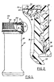
- FIGS. 1 - 3 illustrate a closure and container package 20 in accordance with one presently preferred embodiment of the invention as comprising a container 22 having a body 24 from which a cylindrical finish 26 integrally extends.
- a closure 28 includes a base wall 30 and a cylindrical peripheral skirt 32 having one or more internal threads 34 received over one or more external threads 36 on container finish 26.
- Closure 28 preferably, but not necessarily, additionally includes a tamper - indicating band 38 connected by frangible bridges or a frangible web to the lower edge of skirt 32.
- a stop flange 40 extends from tamper-indicating band 38 into engagement with a bead 42 on container finish 26 so that, when closure 28 is removed from container 22, band 38 is separated from the closure skirt by rupture of the frangible ribs or web.
- closure 28 and package 20 are of generally conventional construction.
- the closure is preferably of molded plastic construction.
- the container may be of glass or plastic construction.
- a liner disk subassembly 44 is loosely captured within closure 28 adjacent to base wall 30.
- Liner disk subassembly 44 includes a plastic circular disk 46 onto the undersurface of which a flexible resilient sealing liner 48 is secured.
- liner 48 does not extend to the peripheral edge of disk 46.
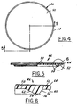
- disk 46 includes a generally flat circular base having a central portion 50 and a peripheral edge 52.
- the disk base, including central portion 50 and peripheral edge portion 52, is of generally uniform thickness in the axial direction, and peripheral edge of the disk extends at constant radius entirely around the axis of the disk.
- a circumferentially continuous annular ring 54 extends axially downwardly from the disk base coaxially with the disk base. Ring 54 is adjacent to but spaced radially inwardly from the peripheral edge of disk 46, effectively separating central portion 50 from peripheral portion 52. As best seen in FIG. 6, ring 54 has a generally S-shaped radially outwardly facing surface formed by a convex portion 56 that extends from the rounded axial edge of ring 54, and a concave portion 58 that extends from convex portion 56 to the flat axially facing surface 60 of disk peripheral portion 52.
- the radially inwardly facing surface 62 of ring 54 is conical.
- a bead 64 extends axially upwardly from peripheral portion 52 around the peripheral edge of the disk for engagement with the opposing undersurface of closure base wall 30 (FIG. 2) to position the body of the disk parallel to but spaced from the opposing surface of the closure base wall.
- Bead 64 may be circumferentially continuous or segmented,
- disk 46 has a nominal outside diameter of 1.477 inches
- ring 54 has a nominal radial thickness of 0.148 inch.
- Surfaces 58, 56 both have a nominal radius of curvature of 0.030 inch, and the portion of ring 54 where surface 56 blends into surface 58 has a nominal angle of 120° with respect to the plane of the disk base.
- Surface 62 has a nominal angle of 27° with respect to the disk plane.
- Bead 64 has a nominal axial height of 0.003 inch.
- Disk base 50 has a nominal thickness of 0.036 inch, and the overall height of the disk base plus ring 54 has a nominal dimension of 0.084 inch.
- Peripheral portion 52 has a nominal radial dimension of 0.081 inch.
- a rounded bead 66 extends radially inwardly from closure skirt 32 adjacent to but spaced from the undersurface of closure base wall 30.
- Bead 66 may be circumferentially continuous or segmented,
- the peripheral portion 52 of disk 46 is loosely captured between bead 66 and base wall 30.
- Liner disk subassembly 44 is loosely captured within the closure shell until the closure is secured to the container finish, at which point the liner disk is tightly clamped between the closure base wall and the container finish.
- Liner 48 is preferably compression molded in situ onto disk 46 while the disk is captured within the closure.
- liner 48 is then compression molded in situ onto the disk.
- the liner may be compression molded onto the disk, and the liner disk subassembly then assembled to the closure.
- Liner 48 may be of any suitable material construction.
- liner 48 is of resin construction, and most preferably includes a barrier material to resist permeation of gases, water vapor and flavorants through the liner.
- the liner is most preferably provided in accordance with the disclosure of one of the European publications noted above, the disclosures of which are incorporated herein by reference.
- Other suitable barrier liners or non-barrier liners may alternatively be provided.
- liner 48 extends over the entire undersurface of disk 46 that is exposed in assembly to the interior of container 22.
- the liner extends over ring 54 and surfaces 56, 58, and onto flat surface 60 for at least a distance sufficient to engage the axial end of container finish 26 when closure 28 is secured to container 22.
- Ring 54 additionally urges the liner into sealing engagement with the radially inner edge of the container finish mouth, so that the liner normally is in sealing engagement with both the axial end and the radially inner edge of the container finish.
- the phantom line 48a shows compression of the peripheral portion of the liner in sealing engagement with the container finish.
- Liner 48 is preferably of uniform thickness over the central portion of disk 46, over ring 54 and onto surface 60.
- liner 48 may have a nominal thickness of 0.025 inch.
- the axial spacing between bead 66 and base wall 30 preferably is such that flange 40 of band 38 abuts bead 42 on finish 26, and fractures the frangible bridges or web, before bead 66 lifts liner disk subassembly 44 out of sealing engagement with the container finish. In this way, the closure will indicate tampering before the seal is broken.
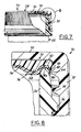
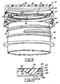
- FIGS. 8 - 10 illustrate a closure and container package 70 in accordance with a modified embodiment of the invention.
- the liner disk subassembly 72 comprises a circular disk 74 and a flexible resilient liner 76 molded thereon.
- Disk 74 includes a central base portion 50 and a peripheral portion 52, from which a circumferentially continuous annular rib 78 integrally extends.
- Rib 78 is disposed at the outer peripheral edge of peripheral disk portion 52, and extends axially therefrom coaxially with the disk base.
- the inner surface 80 of rib 78 is conical, extending axially and radially outwardly from flat surface 60 of disk 74.
- rib 78 has a concave recess or depression 82 that is received by snap fit in assembly over bead 66 on closure skirt 32.
- rib 78 has a nominal axial dimension of 0.060 inch
- surface 82 has a nominal radius of 0.035 inch
- bead 64 has a nominal axial dimension of 0.006 inch
- Liner 76 is molded over the entire undersurface of disk 74, including inside surface 80 of rib 78. As best seen in FIG.
- the liner has a uniform thickness along the central portion of the disk, along ring 54 and along peripheral portion 52, but tapers in thickness axially along surface 80 of rib 78.
- Surfaces 56, 58, 60 and 80 of disk 74 urge liner 76 into sealing engagement with the radially inner edge, the axial end, and the radially outer edge of the container finish.
Abstract
Description
- The present invention is directed to plastic closures for beverage, food, juice, pharmaceutical and like applications, and more particularly to a closure and method of manufacture that are particularly well suited for high-temperature (e.g., pasteurization, hot fill, asceptic fill and retort) applications.
- It has heretofore been proposed to provide a plastic closure for a container, which comprises a plastic cap or shell with an interior liner for sealing engagement with the sealing surface of the container finish. For example, U.S. Patent 4,984,703 discloses a plastic closure that comprises a shell having a base wall with a peripheral skirt and a thread for securing the closure to a container finish, and a sealing liner compression molded in situ on the interior of the shell base wall. U.S. Patent 5,451,360 discloses a method and apparatus for compression molding the liner in situ within the closure shell. It has also been proposed to provide plastic resin barrier materials within the sealing liner for resisting transmission of gases (e.g., carbon dioxide and oxygen), water vapor and/or flavorants through the liner. For example, EP 0926078A1 discloses a plastic closure and method of manufacture in which the liner is compression molded in situ on the interior surface of the closure base wall, and includes a multiplicity of alternating layers of matrix polymer such as EVA and barrier polymer such as EVOH, EP 0926215A1 discloses a plastic closure and method of manufacture in which the liner is compression molded in situ on the interior surface of the closure base wall, and includes a dispersion of barrier polymer platelets, such as EVOH, dispersed within matrix polymer such as EVA.
- Although the closures, the methods of manufacture, and the closure and container packages disclosed in the noted documents have addressed problems theretofore extent in the art, further improvements remain desirable. For example, it is desirable to provide a closure and liner construction, a method of closure manufacture, and a closure and container package that are particularly well adapted for high-temperature applications. Such high-temperature applications include, for example, applications in which the container is filled with product while the product is hot, such as so-called hot fill and asceptic fill applications, High-temperature applications also include applications in which the filled package is subjected to pasteurization or retort after filling. During retort applications, for example, the filled package may be subjected to a temperature of 265° F. for fifteen minutes. High-temperatures situations can also occur when a package is filled with a carbonated beverage and subjected to storage under high-temperature conditions, in which the internal pressure within the container can increase dramatically. In all of such high-temperature situations, the container closure is subjected to elevated internal pressure, which tends to distort or dome the closure base wall and lift the sealing liner away from sealing engagement with the container finish. It is an objective of the present invention to provide a closure, preferably a barrier closure, a method of closure manufacture, and a closure and container package that are particularly well suited for such high-temperature applications, and specifically in which the sealing liner of the closure remains in sealing engagement with the container finish during high-temperature situations.
- The present invention contemplates a number of different aspects or features, which may be implemented separately from or more preferably in combination with each other.
- A two-piece plastic closure in accordance with a first aspect of the present invention comprises a plastic closure shell that includes a base wall and a peripheral skirt with an internal thread or bead for securing the closure to a container finish. A plastic disk is loosely retained within the closure shell parallel to but separate from the base wall. A resilient sealing liner is secured to the disk for sealing engagement with a container finish. The plastic disk preferably includes an annular ring underlying the liner on a side of the disk remote from the base wall. The ring is spaced from the closure skirt for urging the liner against the radially inner edge around the mouth of a container finish when the closure is secured to the container finish. Thus, even if the closure base wall is distorted or domed outwardly during a high-temperature situation, the annular ring maintains the liner in sealing engagement with the radially inner edge of the container finish.
- The disk in the preferred embodiments of this first aspect of the invention preferably includes a flat circular base from which the annular ring extends coaxially with the circular disk periphery. The ring preferably has an S-shaped radially outwardly facing surface, including a rounded convex portion that extends from an axial edge of the ring and a rounded concave portion that extends from the convex portion to a flat axially facing surface on the base of the disk. The liner is urged against the axially facing sealing surface of the container finish and against the radially inner edge of the container finish by this S-shaped ring surface. The base of the disk has a central portion within the ring and a peripheral portion outside of the ring. The liner is preferably of uniform thickness over the central portion of the disk, over the ring and over the peripheral portion of the disk. The disk preferably includes an axially extending bead around a peripheral portion of the disk base to space the disk base from the base wall of the liner. The closure preferably includes a bead extending radially inwardly from the closure skirt adjacent to but spaced from the base wall, and the periphery of the disk is preferably loosely captured between the skirt bead and the base wall.
- In some preferred embodiments in accordance with this first aspect of the invention, the disk further includes an annular rib around a radially outer edge of the disk base extending axially away from the base wall of the closure shell and underlying the liner for engaging the liner against a radially outer edge of the container finish. Thus, in this embodiment, even if the liner becomes separated from the container finish around the radially inner edge of the finish, sealing engagement is maintained between the liner and the container finish around the radially outer edge of the finish. The closure shell preferably has a bead extending radially inwardly from the skirt adjacent to but spaced from the base wall of the closure shell, and the annular rib on the disk preferably has a concave radially outwardly directed surface portion received over the skirt bead for holding the disk and liner in position within the closure.
- In accordance with yet another aspect of the present invention, a method of making a plastic closure includes providing a plastic closure shell having a base wall and a peripheral skirt with an internal thread or bead for securing the closure to a container finish. A plastic disk is placed within the closure shell against the base wall, and a resilient plastic liner is compression molded in situ onto the disk for sealing engagement with a container finish.
- A closure and container package in accordance with a further aspect of the present invention includes a plastic container having a body and a finish with an external thread, and a plastic closure that includes a shell with a base wall and a peripheral skirt with an internal thread securing the closure to the container finish. A plastic disk is retained within the closure shell.
- The invention, together with additional objects, features and advantages thereof, will be best understood from the following description, the appended claims and the accompanying drawings in which:
- FIG. I is a partially sectioned elevational view of a closure and container package in accordance with one presently preferred embodiment of the invention;
- FIG. 2 is a fragmentary sectional view of the portion of the package within the
circle 2 in FIG. 1; - FIG. 3 is a fragmentary exploded perspective view of the container finish and closure in the embodiment of FIG. 1;
- FIG. 4 is a top plan view of the plastic disk in the closure of FIGS. 1 - 3;
- FIG. 5 is a sectional view taken substantially along the line 5 - 5 in FIG. 4;
- FIG. 6 is an enlarged fragmentary sectional view of the portion of the disk within
the
circle 6 in FIG. 5; - FIG. 7 is a fragmentary partially sectioned elevational view of a closure and container package in accordance with a modified embodiment of the invention;
- FIG. 8 is a fragmentary sectional view on an enlarged scale of the portion of the
package within the
circle 8 in FIG. 7; - FIG. 9 is a fragmentary exploded perspective view of the container finish and closure in the package of FIGS. 7 - 8; and
- FIG. 10 is a fragmentary sectional view similar to that of FIG. 6 but illustrating a portion of the closure disk in the package of FIGS. 7 - 9.
-
- FIGS. 1 - 3 illustrate a closure and
container package 20 in accordance with one presently preferred embodiment of the invention as comprising acontainer 22 having abody 24 from which acylindrical finish 26 integrally extends. Aclosure 28 includes abase wall 30 and a cylindricalperipheral skirt 32 having one or moreinternal threads 34 received over one or moreexternal threads 36 oncontainer finish 26. Closure 28 preferably, but not necessarily, additionally includes a tamper - indicatingband 38 connected by frangible bridges or a frangible web to the lower edge ofskirt 32. (Directional words such as "lower" are employed by way of description and not limitation with respect to the upright orientation of the packages illustrated in the drawings, and directional words such as "axially" and "radially" are taken with respect to the axis of the container finish or closure skirt, as applicable. All dimensions are provided by way of example and not limitation.) Astop flange 40 extends from tamper-indicatingband 38 into engagement with abead 42 oncontainer finish 26 so that, whenclosure 28 is removed fromcontainer 22,band 38 is separated from the closure skirt by rupture of the frangible ribs or web. Other types of tamper indicating means may be employed. To the extent thus far described,closure 28 andpackage 20 are of generally conventional construction. The closure is preferably of molded plastic construction. The container may be of glass or plastic construction. - In accordance with one aspect of the present invention, a
liner disk subassembly 44 is loosely captured withinclosure 28 adjacent tobase wall 30.Liner disk subassembly 44 includes a plasticcircular disk 46 onto the undersurface of which a flexibleresilient sealing liner 48 is secured. In the embodiment of FIGS. 1 - 3,liner 48 does not extend to the peripheral edge ofdisk 46. Referring to FIGS. 4 - 6,disk 46 includes a generally flat circular base having acentral portion 50 and aperipheral edge 52. The disk base, includingcentral portion 50 andperipheral edge portion 52, is of generally uniform thickness in the axial direction, and peripheral edge of the disk extends at constant radius entirely around the axis of the disk. A circumferentially continuousannular ring 54 extends axially downwardly from the disk base coaxially with the disk base.Ring 54 is adjacent to but spaced radially inwardly from the peripheral edge ofdisk 46, effectively separatingcentral portion 50 fromperipheral portion 52. As best seen in FIG. 6,ring 54 has a generally S-shaped radially outwardly facing surface formed by aconvex portion 56 that extends from the rounded axial edge ofring 54, and aconcave portion 58 that extends fromconvex portion 56 to the flataxially facing surface 60 of diskperipheral portion 52. The radially inwardly facingsurface 62 ofring 54 is conical. Abead 64 extends axially upwardly fromperipheral portion 52 around the peripheral edge of the disk for engagement with the opposing undersurface of closure base wall 30 (FIG. 2) to position the body of the disk parallel to but spaced from the opposing surface of the closure base wall.Bead 64 may be circumferentially continuous or segmented, In one presently preferred but exemplary embodiment of the invention for a 40mm retortable closure,disk 46 has a nominal outside diameter of 1.477 inches, andring 54 has a nominal radial thickness of 0.148 inch.Surfaces ring 54 wheresurface 56 blends intosurface 58 has a nominal angle of 120° with respect to the plane of the disk base.Surface 62 has a nominal angle of 27° with respect to the disk plane.Bead 64 has a nominal axial height of 0.003 inch.Disk base 50 has a nominal thickness of 0.036 inch, and the overall height of the disk base plusring 54 has a nominal dimension of 0.084 inch.Peripheral portion 52 has a nominal radial dimension of 0.081 inch. - Returning to FIGS. 1 - 3, a
rounded bead 66 extends radially inwardly fromclosure skirt 32 adjacent to but spaced from the undersurface ofclosure base wall 30.Bead 66 may be circumferentially continuous or segmented, Theperipheral portion 52 ofdisk 46 is loosely captured betweenbead 66 andbase wall 30. (Liner disk subassembly 44 is loosely captured within the closure shell until the closure is secured to the container finish, at which point the liner disk is tightly clamped between the closure base wall and the container finish.)Liner 48 is preferably compression molded in situ ontodisk 46 while the disk is captured within the closure. That is,disk 46 is first placed within the closure shell and captured betweenbead 66 andbase wall 30, andliner 48 is then compression molded in situ onto the disk. Alternatively, but less preferably, the liner may be compression molded onto the disk, and the liner disk subassembly then assembled to the closure.Liner 48 may be of any suitable material construction. In accordance with the preferred embodiments of the invention,liner 48 is of resin construction, and most preferably includes a barrier material to resist permeation of gases, water vapor and flavorants through the liner. The liner is most preferably provided in accordance with the disclosure of one of the European publications noted above, the disclosures of which are incorporated herein by reference. Other suitable barrier liners or non-barrier liners may alternatively be provided. It will be noted in FIGS. 1 and 2 thatliner 48 extends over the entire undersurface ofdisk 46 that is exposed in assembly to the interior ofcontainer 22. The liner extends overring 54 and surfaces 56, 58, and ontoflat surface 60 for at least a distance sufficient to engage the axial end ofcontainer finish 26 whenclosure 28 is secured tocontainer 22.Ring 54 additionally urges the liner into sealing engagement with the radially inner edge of the container finish mouth, so that the liner normally is in sealing engagement with both the axial end and the radially inner edge of the container finish. In FIG. 2, the phantom line 48a shows compression of the peripheral portion of the liner in sealing engagement with the container finish.Liner 48 is preferably of uniform thickness over the central portion ofdisk 46, overring 54 and ontosurface 60. By way of example,liner 48 may have a nominal thickness of 0.025 inch. In a tamper-indicating closure, the axial spacing betweenbead 66 andbase wall 30 preferably is such thatflange 40 ofband 38 abutsbead 42 onfinish 26, and fractures the frangible bridges or web, beforebead 66 liftsliner disk subassembly 44 out of sealing engagement with the container finish. In this way, the closure will indicate tampering before the seal is broken. - FIGS. 8 - 10 illustrate a closure and
container package 70 in accordance with a modified embodiment of the invention. (In all embodiments, identical reference numerals are employed to indicate identical or functionally related elements.) Inpackage 70, theliner disk subassembly 72 comprises acircular disk 74 and a flexibleresilient liner 76 molded thereon.Disk 74 includes acentral base portion 50 and aperipheral portion 52, from which a circumferentially continuousannular rib 78 integrally extends.Rib 78 is disposed at the outer peripheral edge ofperipheral disk portion 52, and extends axially therefrom coaxially with the disk base. Theinner surface 80 ofrib 78 is conical, extending axially and radially outwardly fromflat surface 60 ofdisk 74. The radially outer surface ofrib 78 has a concave recess ordepression 82 that is received by snap fit in assembly overbead 66 onclosure skirt 32. In a presently preferred embodiment ofdisk 74 for a 40mm retortable closure,rib 78 has a nominal axial dimension of 0.060 inch,surface 82 has a nominal radius of 0.035 inch, andbead 64 has a nominal axial dimension of 0.006 inch, All other dimensions are the same as those provided in connection withdisk 46 in FIGS. 4 - 6.Liner 76 is molded over the entire undersurface ofdisk 74, including inside surface 80 ofrib 78. As best seen in FIG. 8 with reference tophantom line 76a that shows the initial uncompressed geometry of the liner, the liner has a uniform thickness along the central portion of the disk, alongring 54 and alongperipheral portion 52, but tapers in thickness axially alongsurface 80 ofrib 78.Surfaces disk 74urge liner 76 into sealing engagement with the radially inner edge, the axial end, and the radially outer edge of the container finish. Thus, even if pressure within the container is sufficient to distort or domeclosure base wall 30 anddisk 74 sufficiently for loss of sealing engagement at the radially inner edge of the container finish, sealing engagement is maintained along the radially outer edge of the container finish bydisk rib 78 and the portion of the liner underlying the disk rib. - There have thus been described several embodiments of a plastic closure, a method of making such a closure, and a closure and container package, which fully satisfy all of the objects and aims previously set forth. All of the closures and packages possess superior sealing capability, particularly in high-temperature applications such as hot fill, asceptic fill, pasteurization and retort applications. The closures and packages also achieve superior barrier properties when barrier materials are included in the sealing liners of the closures. The invention has been described in conjunction with a number of aspects and embodiments, and a number of modifications and variations have been discussed. Other modifications and variations will readily suggest themselves to persons of ordinary skill in the art. The invention is intended to embrace all such modifications and variations as fall within the spirt and broad scope of the appended claims.
Claims (18)
- A two-piece plastic closure that includes:a plastic closure shell including abase wall and a peripheral skin with internal means for securing the closure over a container finish, anda plastic disk loosely retained within said shell parallel to but separate from said base wall. and a resilient sealing liner secured to said disk for sealing engagement with a container finish.
- The closure set forth in claim 1 wherein said disk includes an annular ring underlying said liner on a aide of said disk remote from said base wall, said ring being spaced from said skin for urging said liner against a radially inner edge of a container finish when said closure is secured to the container finish.
- The closure set forth in claim 2 wherein said disk comprises a flat base form while said annular ring extends.
- The closure set forth in claim 3 wherein said ring has an S-shaped radially outwardly facing surface, including a rounded convex portion that extends from an axial edge of said ring and a rounded concave portion that extends from said convex portion to a flat axially facing surface of said base.
- The closure set forth in claim 4 wherein said disk base has a central portion within said ring and a peripheral portion outside of said ring, said central and peripheral portions being of identical thickness.
- The closure set forth in claim 5 wherein said liner is of uniform thickness over said central portion. said ring and said peripheral portion of said disk.
- The closure set forth in claim 6 wherein said liner includes a barrier resin material to resist migration of gases, water vapor or flavorants through said liner.
- The closure set forth in claim 5 wherein said disk further includes an axially extending bead around a peripheral portion of said disk base to space said disk base from said base wall of said shell.
- The closure set forth in claim 3 wherein said disk further includes an annular rib around a radially outer edge of said disk base extending away from said base wall and underlying said liner for engaging said liner against a radially outer edge of a container finish when said closure is secured to the container finish.
- The closure set forth in claim 9 wherein said annular rib has a radially inwardly directed surface, onto which a peripheral portion of said liner is molded, that extends axially and radially outwardly from said base of said disk.
- The closure set forth in claim 10 wherein thickness of said liner on said radially inwardly directed surface of said rib is less than the thickness of said liner on said disk base and said ring.
- The closure set forth in claim 10 wherein said closure shell has a bead extending radially inwardly from said skirt adjacent to but spaced from said base wall, and wherein said annular rib has a concave radially outwardly directed surface portion received over said bead.
- The closure set forth in any preceding claim wherein said closure shell includes a bead extending radially inwardly from said skirt at a position spaced from said base wall, and wherein said disk and liner are loosely captured between said bead and said base wall.
- The closure set forth in claim 13 wherein said closure shell further includes a tamper-indicating band connected by frangible means to a lower edge of said skirt for abutment with a stop on the container finish, spacing between said bead and said base wall being such that said band abuts the stop and fractures said frangible means before said bead lifts said disk and liner from sealing engagement with the container finish.
- The closure set forth in any preceding claim wherein said liner includes a barrier material against migration of gases, water vapor or flavorants through said liner.
- The closure set forth in any preceding claim wherein said liner is molded in situ onto said disk within said closure.
- A closure and container package that includes;a container including a body and a finish with an external thread, anda plastic closure as set forth in any preceding claim.
- A method of making a two-piece plastic closure as set forth in any preceding claim that includes:(a) providing a plastic closure shell that includes a base wall and a peripheral skirt with internal means for securing the closure to a container finish.(b) placing a plastic disk within said closure shell against said base wall, and(c) compression molding a resilient plastic liner in situ onto said disk for sealing engagement with a container finish.
Applications Claiming Priority (2)
| Application Number | Priority Date | Filing Date | Title |
|---|---|---|---|
| US09/994,554 US20030098286A1 (en) | 2001-11-27 | 2001-11-27 | Plastic closure, method of manufacture, and closure and container package for high-temperature applications |
| US994554 | 2001-11-27 |
Publications (3)
| Publication Number | Publication Date |
|---|---|
| EP1329393A2 true EP1329393A2 (en) | 2003-07-23 |
| EP1329393A3 EP1329393A3 (en) | 2003-08-06 |
| EP1329393B1 EP1329393B1 (en) | 2006-09-13 |
Family
ID=25540793
Family Applications (1)
| Application Number | Title | Priority Date | Filing Date |
|---|---|---|---|
| EP02258167A Expired - Lifetime EP1329393B1 (en) | 2001-11-27 | 2002-11-27 | Plastic closure, container equipped with it and method of manufacture |
Country Status (16)
| Country | Link |
|---|---|
| US (1) | US20030098286A1 (en) |
| EP (1) | EP1329393B1 (en) |
| JP (1) | JP4165696B2 (en) |
| CN (1) | CN1294055C (en) |
| AT (1) | ATE339367T1 (en) |
| AU (1) | AU2002306198B2 (en) |
| BR (1) | BR0204777B1 (en) |
| CA (1) | CA2412357C (en) |
| DE (1) | DE60214662T2 (en) |
| ES (1) | ES2273975T3 (en) |
| HU (1) | HU226940B1 (en) |
| MX (1) | MXPA02011665A (en) |
| NZ (1) | NZ522784A (en) |
| PL (1) | PL205128B1 (en) |
| SG (1) | SG112861A1 (en) |
| TW (1) | TW200300400A (en) |
Families Citing this family (54)
| Publication number | Priority date | Publication date | Assignee | Title |
|---|---|---|---|---|
| US7669390B2 (en) | 2004-03-08 | 2010-03-02 | Medical Instill Technologies, Inc. | Method for molding and assembling containers with stoppers and filling same |
| US7243689B2 (en) | 2000-02-11 | 2007-07-17 | Medical Instill Technologies, Inc. | Device with needle penetrable and laser resealable portion and related method |
| US7707807B2 (en) * | 2004-03-08 | 2010-05-04 | Medical Instill Technologies, Inc. | Apparatus for molding and assembling containers with stoppers and filling same |
| WO2003028785A2 (en) * | 2001-10-03 | 2003-04-10 | Medical Instill Technologies, Inc. | Syringe and reconstitution syringe |
| WO2003033363A1 (en) * | 2001-10-16 | 2003-04-24 | Medical Instill Technologies, Inc. | Dispenser with sealed chamber and one-way valve for providing metered amounts of substances |
| US7798185B2 (en) | 2005-08-01 | 2010-09-21 | Medical Instill Technologies, Inc. | Dispenser and method for storing and dispensing sterile food product |
| JP3994146B2 (en) * | 2001-12-18 | 2007-10-17 | 株式会社吉野工業所 | Synthetic resin container body and preform mold equipment |
| FR2837173B1 (en) * | 2002-03-13 | 2004-05-28 | Tetra Laval Holdings & Finance | DEVICE FOR SEALING A CONTAINER AND CONTAINER PROVIDED WITH SUCH A DEVICE |
| US20030222046A1 (en) * | 2002-04-11 | 2003-12-04 | Schenck Timothy T. | Plastic barrier closure and method of fabrication |
| CA2489804C (en) | 2002-06-19 | 2008-03-25 | Medical Instill Technologies, Inc. | Sterile filling machine having needle filling station within e-beam chamber |
| US6874647B2 (en) * | 2002-08-12 | 2005-04-05 | Owens-Illinois Closure Inc. | Plastic closure, closure and container package, and method of manufacture |
| US7611026B1 (en) | 2002-08-12 | 2009-11-03 | Rexam Closure Systems Inc. | Tamper-evident closure having a sealing disk and package for high-temperature applications |
| MXPA05002458A (en) * | 2002-09-03 | 2005-09-30 | Medical Instill Tech Inc | Sealed containers and methods of making and filling same. |
| EP1716053B1 (en) * | 2004-01-23 | 2007-05-16 | Owens-Illinois Closure, Inc. | Plastic closure, closure and container package, and method of manufacture |
| GB2412366B (en) * | 2004-03-24 | 2006-09-06 | Spreckelsen Mcgeough Ltd | Closure with integral gas barrier |
| CN101005997A (en) * | 2004-06-18 | 2007-07-25 | 希尔康白帽美国有限公司 | Composite closure with barrier end panel |
| US20060073293A1 (en) * | 2004-10-04 | 2006-04-06 | Nahill Thomas E | Finish assembly, preform assembly, container assembly, and method of manufacture |
| US20060163191A1 (en) * | 2005-01-19 | 2006-07-27 | Laveault Richard A | Sealing liner for a closure |
| JP4657739B2 (en) * | 2005-01-25 | 2011-03-23 | 吉田プラ工業株式会社 | Positioning container |
| US20060278601A1 (en) * | 2005-06-10 | 2006-12-14 | Owens-Illinois Closure Inc. | Plastic closure, closure and container package, and method of manufacture |
| US8071009B2 (en) * | 2005-10-17 | 2011-12-06 | Medical Instill Technologies, Inc. | Sterile de-molding apparatus and method |
| JP2009522179A (en) * | 2005-12-28 | 2009-06-11 | シルガン・ホワイト・キャップ・アメリカズ・エルエルシー | Retort package with plastic closure cap |
| JP4753806B2 (en) * | 2006-06-29 | 2011-08-24 | 株式会社吉野工業所 | Plastic cap |
| US7942281B2 (en) * | 2007-03-29 | 2011-05-17 | Rexam Closure Systems, Inc. | Closure and package with flexible base wall panel |
| DE102007033621B4 (en) * | 2007-07-17 | 2022-06-15 | Krones Aktiengesellschaft | Plastic container with grip groove |
| US20100065528A1 (en) * | 2008-02-29 | 2010-03-18 | Universal Can Corporation | Liner-provided cap and cap-provided threaded container |
| JP5341369B2 (en) * | 2008-02-29 | 2013-11-13 | ユニバーサル製缶株式会社 | Cap with liner and bottle with cap |
| US20100176134A1 (en) * | 2008-07-22 | 2010-07-15 | Cramer Kenneth M | Retortable Closures and Containers |
| FR2950035B1 (en) | 2009-09-15 | 2011-09-02 | Raymond A & Cie | LOCKING COIFFE FOR CONTAINER WITH COLLAR |
| FR2950865B1 (en) | 2009-10-01 | 2011-10-28 | Raymond A & Cie | LOCKING CAP FOR A COLLARED CONTAINER WITH A FASTENING CAPSULE |
| JP5414616B2 (en) | 2010-05-14 | 2014-02-12 | ユニバーサル製缶株式会社 | Metal cap and bottle with cap |
| USD760911S1 (en) | 2011-12-15 | 2016-07-05 | Shahid Sheikh | Ice bag cap |
| US9650179B2 (en) | 2011-12-15 | 2017-05-16 | Proseries Llc | Cap with overmolded gasket anchoring system |
| US20130158637A1 (en) * | 2011-12-15 | 2013-06-20 | Shahid Sheikh | Ice Bag Closures and Methods for Manufacturing Ice Bag Closures |
| USD766717S1 (en) | 2011-12-15 | 2016-09-20 | Shahid Sheikh | Ice bag cap |
| EP2607252B1 (en) * | 2011-12-19 | 2016-11-02 | KISIKO Kirchner, Simon & Co. GmbH | Assembly of a container made of tubing glass and a one piece closure for the container |
| FR2986782B1 (en) | 2012-02-13 | 2014-03-07 | Raymond A & Cie | PLUG LOCKING DEVICE ON FLANGE CONTAINER, PLUG-IN CLOSURE FLANGE CONTAINER PROVIDED WITH SUCH LATCHING DEVICE |
| US9682805B2 (en) | 2012-10-26 | 2017-06-20 | Berry Plastics Corporation | Closure for container |
| BR112015014263A2 (en) * | 2012-12-20 | 2017-07-11 | Abbott Lab | perfected bottle |
| JP6164606B2 (en) * | 2013-03-14 | 2017-07-19 | ユニバーサル製缶株式会社 | Container with cap |
| JP5843807B2 (en) * | 2013-05-31 | 2016-01-13 | ユニバーサル製缶株式会社 | Cap with liner and method for producing bottle with cap |
| US10689164B2 (en) | 2014-01-03 | 2020-06-23 | Sonoco Development, Inc. | Container with heat-sealed composite plastic and metal screw closure |
| CN104367094B (en) * | 2014-10-21 | 2017-01-11 | 杭州康永生物技术有限公司 | Sealing ring and cup cover |
| MX2017013903A (en) | 2015-04-30 | 2018-03-01 | Berry Plastics Corp | Container closure. |
| USD805395S1 (en) | 2015-09-02 | 2017-12-19 | Abbott Laboratories | Bottle |
| GB201601789D0 (en) * | 2016-02-01 | 2016-03-16 | Obrist Closures Switzerland | Improvements in or relating to tamper-evident closures |
| US10793326B2 (en) * | 2016-10-06 | 2020-10-06 | Closure Systems International Inc. | Closure for a package |
| US11305923B2 (en) | 2016-10-06 | 2022-04-19 | Closure Systems International Inc. | Closure for a package |
| CN111108045B (en) * | 2017-09-22 | 2022-01-11 | 大和制罐株式会社 | Cap, mold, and cap manufacturing method |
| CN108163350A (en) * | 2018-02-02 | 2018-06-15 | 台山市凯德利盖业有限公司 | A kind of seal bottle cap |
| JP2020015548A (en) * | 2018-07-27 | 2020-01-30 | 大和製罐株式会社 | cap |
| JP7203570B2 (en) | 2018-10-31 | 2023-01-13 | 大和製罐株式会社 | cap |
| JP2022180910A (en) * | 2021-05-25 | 2022-12-07 | サーモス株式会社 | Cap unit and container with cap |
| DE102022108162A1 (en) | 2022-04-05 | 2023-10-05 | Schoeller Allibert Gmbh | Container with a screw cap |
Citations (4)
| Publication number | Priority date | Publication date | Assignee | Title |
|---|---|---|---|---|
| US4984703A (en) | 1989-10-03 | 1991-01-15 | Owens-Illinois Closure Inc. | Plastic closure with compression molded sealing liner |
| US5451360A (en) | 1993-10-14 | 1995-09-19 | Owens-Illinois Closure Inc. | Method and apparatus for compression molding closure liners |
| EP0926078A1 (en) | 1997-12-24 | 1999-06-30 | Owens-Illinois Closure Inc. | Plastic closure with compression molded sealing/barrier liner |
| EP0926215A1 (en) | 1997-12-24 | 1999-06-30 | Owens-Illinois Closure Inc. | Plastic closure with compression molded barrier liner |
Family Cites Families (22)
| Publication number | Priority date | Publication date | Assignee | Title |
|---|---|---|---|---|
| US3425579A (en) * | 1967-06-15 | 1969-02-04 | Braun Co W | Means for effectively sealing a bottle or container |
| US3433380A (en) * | 1967-10-23 | 1969-03-18 | Loy Bros Proprietary Ltd | Container closure |
| US3536224A (en) * | 1969-07-14 | 1970-10-27 | Kerr Glass Mfg Corp | Molded-in liner for a closure |
| US4093094A (en) * | 1977-03-28 | 1978-06-06 | Owens-Illinois, Inc. | Home canning system |
| US4717034A (en) * | 1982-07-06 | 1988-01-05 | Owens-Illinois Closure Inc. | One-piece thermoplastic closure having press-on screw off structure including spaced vertical ribs in the skirt of the closure |
| US4674642A (en) * | 1984-09-07 | 1987-06-23 | Tbl Development Corporation | Pressure-indicative container closure |
| US4640428A (en) * | 1985-09-03 | 1987-02-03 | Owens-Illinois, Inc. | High gas barrier plastic closure |
| US4896782A (en) * | 1989-02-13 | 1990-01-30 | Sunbeam Plastics Corporation | Closure with insert for enhanced sealing |
| US5031787A (en) * | 1989-09-01 | 1991-07-16 | Anchor Hocking Packaging Company | Low height floating disk closure |
| IT1236687B (en) * | 1989-11-09 | 1993-03-26 | Guala Spa | WARRANTY CLOSURE, FOR LIQUOR BOTTLES AND SIMILAR. |
| US5346082A (en) * | 1992-06-12 | 1994-09-13 | Anchor Hocking Packaging Co. | Composite closure with sealing force indicating means and ratchet operated tamper indicating band |
| US5285913A (en) * | 1992-11-24 | 1994-02-15 | H-C Industries, Inc. | Closure assembly with insert liner |
| US5356021A (en) * | 1993-09-30 | 1994-10-18 | H-C Industries, Inc. | Container closure with multiple liner seals |
| JP2943048B2 (en) * | 1994-08-06 | 1999-08-30 | 日本山村硝子株式会社 | Pill fur proof cap made of synthetic resin |
| US5839592A (en) * | 1995-06-09 | 1998-11-24 | Anchor Hocking Packaging Co. | Plastic closure |
| US5997684A (en) * | 1997-10-31 | 1999-12-07 | Owens-Illinois Closure Inc. | Method and apparatus for assembling a sealing liner to a plastic closure |
| FR2783240B1 (en) * | 1998-09-16 | 2000-12-08 | Novembal Sa | CAP WITH A SEALING GASKET, PROCESS FOR MAKING SUCH A CAP AND ASSEMBLY INCLUDING A CONTAINER AND THE SAID PLUG WITH A SEAL |
| US6500376B1 (en) * | 2000-01-27 | 2002-12-31 | Visteon Global Technologies, Inc. | Multiple injection compression molding process |
| US6491175B1 (en) * | 2000-06-28 | 2002-12-10 | Saad Taha | Single piece closure for a pressurized container |
| US6761275B1 (en) * | 2000-07-14 | 2004-07-13 | Alcoa Closure Systems International | Domed liner disc for closure |
| EP1318949A2 (en) * | 2000-09-20 | 2003-06-18 | Alcoa Closure Systems International, Inc. | Venting plastic closure |
| US6874647B2 (en) * | 2002-08-12 | 2005-04-05 | Owens-Illinois Closure Inc. | Plastic closure, closure and container package, and method of manufacture |
-
2001
- 2001-11-27 US US09/994,554 patent/US20030098286A1/en not_active Abandoned
-
2002
- 2002-11-22 CA CA002412357A patent/CA2412357C/en not_active Expired - Fee Related
- 2002-11-26 NZ NZ522784A patent/NZ522784A/en not_active IP Right Cessation
- 2002-11-26 MX MXPA02011665A patent/MXPA02011665A/en active IP Right Grant
- 2002-11-26 CN CNB021281718A patent/CN1294055C/en not_active Expired - Fee Related
- 2002-11-26 HU HU0204067A patent/HU226940B1/en not_active IP Right Cessation
- 2002-11-26 TW TW091134371A patent/TW200300400A/en unknown
- 2002-11-27 JP JP2002382720A patent/JP4165696B2/en not_active Expired - Fee Related
- 2002-11-27 SG SG200207199A patent/SG112861A1/en unknown
- 2002-11-27 BR BRPI0204777-2A patent/BR0204777B1/en not_active IP Right Cessation
- 2002-11-27 AU AU2002306198A patent/AU2002306198B2/en not_active Ceased
- 2002-11-27 DE DE60214662T patent/DE60214662T2/en not_active Expired - Lifetime
- 2002-11-27 EP EP02258167A patent/EP1329393B1/en not_active Expired - Lifetime
- 2002-11-27 ES ES02258167T patent/ES2273975T3/en not_active Expired - Lifetime
- 2002-11-27 AT AT02258167T patent/ATE339367T1/en not_active IP Right Cessation
- 2002-11-27 PL PL357404A patent/PL205128B1/en not_active IP Right Cessation
Patent Citations (4)
| Publication number | Priority date | Publication date | Assignee | Title |
|---|---|---|---|---|
| US4984703A (en) | 1989-10-03 | 1991-01-15 | Owens-Illinois Closure Inc. | Plastic closure with compression molded sealing liner |
| US5451360A (en) | 1993-10-14 | 1995-09-19 | Owens-Illinois Closure Inc. | Method and apparatus for compression molding closure liners |
| EP0926078A1 (en) | 1997-12-24 | 1999-06-30 | Owens-Illinois Closure Inc. | Plastic closure with compression molded sealing/barrier liner |
| EP0926215A1 (en) | 1997-12-24 | 1999-06-30 | Owens-Illinois Closure Inc. | Plastic closure with compression molded barrier liner |
Also Published As
| Publication number | Publication date |
|---|---|
| CN1426930A (en) | 2003-07-02 |
| HU226940B1 (en) | 2010-03-29 |
| HUP0204067A2 (en) | 2003-07-28 |
| NZ522784A (en) | 2003-11-28 |
| HUP0204067A3 (en) | 2004-06-28 |
| PL205128B1 (en) | 2010-03-31 |
| HU0204067D0 (en) | 2003-01-28 |
| JP4165696B2 (en) | 2008-10-15 |
| CA2412357C (en) | 2008-12-30 |
| US20030098286A1 (en) | 2003-05-29 |
| TW200300400A (en) | 2003-06-01 |
| ATE339367T1 (en) | 2006-10-15 |
| JP2003200960A (en) | 2003-07-15 |
| PL357404A1 (en) | 2003-06-02 |
| MXPA02011665A (en) | 2004-09-03 |
| SG112861A1 (en) | 2005-07-28 |
| EP1329393A3 (en) | 2003-08-06 |
| DE60214662T2 (en) | 2007-09-27 |
| AU2002306198B2 (en) | 2009-04-02 |
| EP1329393B1 (en) | 2006-09-13 |
| CN1294055C (en) | 2007-01-10 |
| DE60214662D1 (en) | 2006-10-26 |
| BR0204777A (en) | 2004-06-15 |
| CA2412357A1 (en) | 2003-05-27 |
| ES2273975T3 (en) | 2007-05-16 |
| BR0204777B1 (en) | 2011-01-25 |
Similar Documents
| Publication | Publication Date | Title |
|---|---|---|
| EP1329393B1 (en) | Plastic closure, container equipped with it and method of manufacture | |
| US6874647B2 (en) | Plastic closure, closure and container package, and method of manufacture | |
| US7611026B1 (en) | Tamper-evident closure having a sealing disk and package for high-temperature applications | |
| EP1470054B1 (en) | Composite closure having disk tightening feature | |
| US5265747A (en) | Plastic beverage closure | |
| WO2007015751A1 (en) | Child-resistant closure and package convertible to non-child-resistant operation | |
| US20020162818A1 (en) | Beverage container closure | |
| WO2006062896A2 (en) | Threaded container closure | |
| NZ545492A (en) | A conduit threading device and method of introducing electrical wire or communications cable, or both, into a conduit | |
| US7922017B2 (en) | Child-resistant closure, container and package convertible to non-child-resistant operation | |
| US6769559B2 (en) | Venting plastic closure | |
| EP1716053B1 (en) | Plastic closure, closure and container package, and method of manufacture | |
| MXPA03001548A (en) | Tamper-indicating closure and package. | |
| EP1048583A1 (en) | Lined closure for containers of differing finish configurations | |
| US20070163988A1 (en) | Container package having improved seal | |
| WO1997031834A1 (en) | A screw cap of plastics material | |
| WO1996041751A1 (en) | Closure | |
| MX2008001071A (en) | Child-resistant closure and package convertible to non-child-resistant operation | |
| JPH04128252U (en) | Synthetic resin cap |
Legal Events
| Date | Code | Title | Description |
|---|---|---|---|
| PUAI | Public reference made under article 153(3) epc to a published international application that has entered the european phase |
Free format text: ORIGINAL CODE: 0009012 |
|
| PUAL | Search report despatched |
Free format text: ORIGINAL CODE: 0009013 |
|
| AK | Designated contracting states |
Designated state(s): AT BE BG CH CY CZ DE DK EE ES FI FR GB GR IE IT LI LU MC NL PT SE SK TR |
|
| AX | Request for extension of the european patent |
Extension state: AL LT LV MK RO SI |
|
| AK | Designated contracting states |
Designated state(s): AT BE BG CH CY CZ DE DK EE ES FI FR GB GR IE IT LI LU MC NL PT SE SK TR |
|
| AX | Request for extension of the european patent |
Extension state: AL LT LV MK RO SI |
|
| RIC1 | Information provided on ipc code assigned before grant |
Ipc: 7B 29C 70/80 B Ipc: 7B 65D 41/04 A |
|
| AKX | Designation fees paid | ||
| 17P | Request for examination filed |
Effective date: 20040126 |
|
| RBV | Designated contracting states (corrected) |
Designated state(s): AT BE BG CH LI |
|
| REG | Reference to a national code |
Ref country code: DE Ref legal event code: 8566 |
|
| RBV | Designated contracting states (corrected) |
Designated state(s): AT BE BG CH CY CZ DE DK EE ES FI FR GB GR IE IT LI LU MC NL PT SE SK TR |
|
| GRAP | Despatch of communication of intention to grant a patent |
Free format text: ORIGINAL CODE: EPIDOSNIGR1 |
|
| GRAS | Grant fee paid |
Free format text: ORIGINAL CODE: EPIDOSNIGR3 |
|
| GRAA | (expected) grant |
Free format text: ORIGINAL CODE: 0009210 |
|
| AK | Designated contracting states |
Kind code of ref document: B1 Designated state(s): AT BE BG CH CY CZ DE DK EE ES FI FR GB GR IE IT LI LU MC NL PT SE SK TR |
|
| PG25 | Lapsed in a contracting state [announced via postgrant information from national office to epo] |
Ref country code: IT Free format text: LAPSE BECAUSE OF FAILURE TO SUBMIT A TRANSLATION OF THE DESCRIPTION OR TO PAY THE FEE WITHIN THE PRESCRIBED TIME-LIMIT;WARNING: LAPSES OF ITALIAN PATENTS WITH EFFECTIVE DATE BEFORE 2007 MAY HAVE OCCURRED AT ANY TIME BEFORE 2007. THE CORRECT EFFECTIVE DATE MAY BE DIFFERENT FROM THE ONE RECORDED. Effective date: 20060913 Ref country code: CH Free format text: LAPSE BECAUSE OF FAILURE TO SUBMIT A TRANSLATION OF THE DESCRIPTION OR TO PAY THE FEE WITHIN THE PRESCRIBED TIME-LIMIT Effective date: 20060913 Ref country code: LI Free format text: LAPSE BECAUSE OF FAILURE TO SUBMIT A TRANSLATION OF THE DESCRIPTION OR TO PAY THE FEE WITHIN THE PRESCRIBED TIME-LIMIT Effective date: 20060913 Ref country code: SK Free format text: LAPSE BECAUSE OF FAILURE TO SUBMIT A TRANSLATION OF THE DESCRIPTION OR TO PAY THE FEE WITHIN THE PRESCRIBED TIME-LIMIT Effective date: 20060913 Ref country code: BE Free format text: LAPSE BECAUSE OF FAILURE TO SUBMIT A TRANSLATION OF THE DESCRIPTION OR TO PAY THE FEE WITHIN THE PRESCRIBED TIME-LIMIT Effective date: 20060913 Ref country code: NL Free format text: LAPSE BECAUSE OF FAILURE TO SUBMIT A TRANSLATION OF THE DESCRIPTION OR TO PAY THE FEE WITHIN THE PRESCRIBED TIME-LIMIT Effective date: 20060913 Ref country code: CZ Free format text: LAPSE BECAUSE OF FAILURE TO SUBMIT A TRANSLATION OF THE DESCRIPTION OR TO PAY THE FEE WITHIN THE PRESCRIBED TIME-LIMIT Effective date: 20060913 Ref country code: AT Free format text: LAPSE BECAUSE OF FAILURE TO SUBMIT A TRANSLATION OF THE DESCRIPTION OR TO PAY THE FEE WITHIN THE PRESCRIBED TIME-LIMIT Effective date: 20060913 |
|
| REG | Reference to a national code |
Ref country code: GB Ref legal event code: FG4D |
|
| REG | Reference to a national code |
Ref country code: CH Ref legal event code: EP |
|
| REG | Reference to a national code |
Ref country code: IE Ref legal event code: FG4D |
|
| REF | Corresponds to: |
Ref document number: 60214662 Country of ref document: DE Date of ref document: 20061026 Kind code of ref document: P |
|
| RAP2 | Party data changed (patent owner data changed or rights of a patent transferred) |
Owner name: OWENS-ILLINOIS CLOSURE, INC. |
|
| PG25 | Lapsed in a contracting state [announced via postgrant information from national office to epo] |
Ref country code: IE Free format text: LAPSE BECAUSE OF NON-PAYMENT OF DUE FEES Effective date: 20061127 |
|
| PG25 | Lapsed in a contracting state [announced via postgrant information from national office to epo] |
Ref country code: MC Free format text: LAPSE BECAUSE OF NON-PAYMENT OF DUE FEES Effective date: 20061130 |
|
| PG25 | Lapsed in a contracting state [announced via postgrant information from national office to epo] |
Ref country code: BG Free format text: LAPSE BECAUSE OF FAILURE TO SUBMIT A TRANSLATION OF THE DESCRIPTION OR TO PAY THE FEE WITHIN THE PRESCRIBED TIME-LIMIT Effective date: 20061213 Ref country code: DK Free format text: LAPSE BECAUSE OF FAILURE TO SUBMIT A TRANSLATION OF THE DESCRIPTION OR TO PAY THE FEE WITHIN THE PRESCRIBED TIME-LIMIT Effective date: 20061213 Ref country code: SE Free format text: LAPSE BECAUSE OF FAILURE TO SUBMIT A TRANSLATION OF THE DESCRIPTION OR TO PAY THE FEE WITHIN THE PRESCRIBED TIME-LIMIT Effective date: 20061213 |
|
| NLT2 | Nl: modifications (of names), taken from the european patent patent bulletin |
Owner name: OWENS-ILLINOIS CLOSURE, INC. Effective date: 20061115 |
|
| PG25 | Lapsed in a contracting state [announced via postgrant information from national office to epo] |
Ref country code: PT Free format text: LAPSE BECAUSE OF FAILURE TO SUBMIT A TRANSLATION OF THE DESCRIPTION OR TO PAY THE FEE WITHIN THE PRESCRIBED TIME-LIMIT Effective date: 20070226 |
|
| NLV1 | Nl: lapsed or annulled due to failure to fulfill the requirements of art. 29p and 29m of the patents act | ||
| REG | Reference to a national code |
Ref country code: CH Ref legal event code: PL |
|
| ET | Fr: translation filed | ||
| REG | Reference to a national code |
Ref country code: ES Ref legal event code: FG2A Ref document number: 2273975 Country of ref document: ES Kind code of ref document: T3 |
|
| PLBE | No opposition filed within time limit |
Free format text: ORIGINAL CODE: 0009261 |
|
| STAA | Information on the status of an ep patent application or granted ep patent |
Free format text: STATUS: NO OPPOSITION FILED WITHIN TIME LIMIT |
|
| 26N | No opposition filed |
Effective date: 20070614 |
|
| PG25 | Lapsed in a contracting state [announced via postgrant information from national office to epo] |
Ref country code: GR Free format text: LAPSE BECAUSE OF FAILURE TO SUBMIT A TRANSLATION OF THE DESCRIPTION OR TO PAY THE FEE WITHIN THE PRESCRIBED TIME-LIMIT Effective date: 20061214 |
|
| PG25 | Lapsed in a contracting state [announced via postgrant information from national office to epo] |
Ref country code: FI Free format text: LAPSE BECAUSE OF FAILURE TO SUBMIT A TRANSLATION OF THE DESCRIPTION OR TO PAY THE FEE WITHIN THE PRESCRIBED TIME-LIMIT Effective date: 20060913 Ref country code: EE Free format text: LAPSE BECAUSE OF FAILURE TO SUBMIT A TRANSLATION OF THE DESCRIPTION OR TO PAY THE FEE WITHIN THE PRESCRIBED TIME-LIMIT Effective date: 20060913 |
|
| PG25 | Lapsed in a contracting state [announced via postgrant information from national office to epo] |
Ref country code: LU Free format text: LAPSE BECAUSE OF NON-PAYMENT OF DUE FEES Effective date: 20061127 Ref country code: TR Free format text: LAPSE BECAUSE OF FAILURE TO SUBMIT A TRANSLATION OF THE DESCRIPTION OR TO PAY THE FEE WITHIN THE PRESCRIBED TIME-LIMIT Effective date: 20060913 |
|
| REG | Reference to a national code |
Ref country code: FR Ref legal event code: CD Ref country code: FR Ref legal event code: CA |
|
| PG25 | Lapsed in a contracting state [announced via postgrant information from national office to epo] |
Ref country code: CY Free format text: LAPSE BECAUSE OF FAILURE TO SUBMIT A TRANSLATION OF THE DESCRIPTION OR TO PAY THE FEE WITHIN THE PRESCRIBED TIME-LIMIT Effective date: 20060913 |
|
| PGFP | Annual fee paid to national office [announced via postgrant information from national office to epo] |
Ref country code: ES Payment date: 20091201 Year of fee payment: 8 |
|
| PGFP | Annual fee paid to national office [announced via postgrant information from national office to epo] |
Ref country code: IT Payment date: 20091119 Year of fee payment: 8 |
|
| PGFP | Annual fee paid to national office [announced via postgrant information from national office to epo] |
Ref country code: DE Payment date: 20101124 Year of fee payment: 9 |
|
| PGFP | Annual fee paid to national office [announced via postgrant information from national office to epo] |
Ref country code: GB Payment date: 20101124 Year of fee payment: 9 |
|
| PG25 | Lapsed in a contracting state [announced via postgrant information from national office to epo] |
Ref country code: IT Free format text: LAPSE BECAUSE OF NON-PAYMENT OF DUE FEES Effective date: 20101127 |
|
| REG | Reference to a national code |
Ref country code: ES Ref legal event code: FD2A Effective date: 20120305 |
|
| PG25 | Lapsed in a contracting state [announced via postgrant information from national office to epo] |
Ref country code: ES Free format text: LAPSE BECAUSE OF NON-PAYMENT OF DUE FEES Effective date: 20101128 |
|
| PGFP | Annual fee paid to national office [announced via postgrant information from national office to epo] |
Ref country code: FR Payment date: 20121113 Year of fee payment: 11 |
|
| GBPC | Gb: european patent ceased through non-payment of renewal fee |
Effective date: 20121127 |
|
| REG | Reference to a national code |
Ref country code: DE Ref legal event code: R119 Ref document number: 60214662 Country of ref document: DE Effective date: 20130601 |
|
| PG25 | Lapsed in a contracting state [announced via postgrant information from national office to epo] |
Ref country code: DE Free format text: LAPSE BECAUSE OF NON-PAYMENT OF DUE FEES Effective date: 20130601 |
|
| PG25 | Lapsed in a contracting state [announced via postgrant information from national office to epo] |
Ref country code: GB Free format text: LAPSE BECAUSE OF NON-PAYMENT OF DUE FEES Effective date: 20121127 |
|
| REG | Reference to a national code |
Ref country code: FR Ref legal event code: ST Effective date: 20140731 |
|
| PG25 | Lapsed in a contracting state [announced via postgrant information from national office to epo] |
Ref country code: FR Free format text: LAPSE BECAUSE OF NON-PAYMENT OF DUE FEES Effective date: 20131202 |