EP1332364B1 - In vivo detection of biomolecule concentrations using fluorescent tags - Google Patents
In vivo detection of biomolecule concentrations using fluorescent tags Download PDFInfo
- Publication number
- EP1332364B1 EP1332364B1 EP01986125A EP01986125A EP1332364B1 EP 1332364 B1 EP1332364 B1 EP 1332364B1 EP 01986125 A EP01986125 A EP 01986125A EP 01986125 A EP01986125 A EP 01986125A EP 1332364 B1 EP1332364 B1 EP 1332364B1
- Authority
- EP
- European Patent Office
- Prior art keywords
- optical radiation
- fluorescently labelled
- vivo
- tissue
- antibodies
- Prior art date
- Legal status (The legal status is an assumption and is not a legal conclusion. Google has not performed a legal analysis and makes no representation as to the accuracy of the status listed.)
- Expired - Lifetime
Links
Images


Classifications
-
- A—HUMAN NECESSITIES
- A61—MEDICAL OR VETERINARY SCIENCE; HYGIENE
- A61B—DIAGNOSIS; SURGERY; IDENTIFICATION
- A61B5/00—Measuring for diagnostic purposes; Identification of persons
- A61B5/0059—Measuring for diagnostic purposes; Identification of persons using light, e.g. diagnosis by transillumination, diascopy, fluorescence
- A61B5/0071—Measuring for diagnostic purposes; Identification of persons using light, e.g. diagnosis by transillumination, diascopy, fluorescence by measuring fluorescence emission
-
- A—HUMAN NECESSITIES
- A61—MEDICAL OR VETERINARY SCIENCE; HYGIENE
- A61B—DIAGNOSIS; SURGERY; IDENTIFICATION
- A61B5/00—Measuring for diagnostic purposes; Identification of persons
- A61B5/0059—Measuring for diagnostic purposes; Identification of persons using light, e.g. diagnosis by transillumination, diascopy, fluorescence
- A61B5/0082—Measuring for diagnostic purposes; Identification of persons using light, e.g. diagnosis by transillumination, diascopy, fluorescence adapted for particular medical purposes
- A61B5/0084—Measuring for diagnostic purposes; Identification of persons using light, e.g. diagnosis by transillumination, diascopy, fluorescence adapted for particular medical purposes for introduction into the body, e.g. by catheters
-
- A—HUMAN NECESSITIES
- A61—MEDICAL OR VETERINARY SCIENCE; HYGIENE
- A61K—PREPARATIONS FOR MEDICAL, DENTAL OR TOILETRY PURPOSES
- A61K49/00—Preparations for testing in vivo
- A61K49/001—Preparation for luminescence or biological staining
- A61K49/0013—Luminescence
- A61K49/0017—Fluorescence in vivo
- A61K49/005—Fluorescence in vivo characterised by the carrier molecule carrying the fluorescent agent
- A61K49/0058—Antibodies
Definitions
- the present invention relates to the field of sensors, and more particularly, to biomolecular sensors.
- tumors may have periods in which they are more susceptible to treatment by radiation or drug therapy.
- Providing a monitoring system which can continuously or semi-continuously monitor and potentially identify such a susceptible condition could provide increases in tumor destruction rates.
- TSA tumor specific antigens
- sigma-2 receptors found on the surface of cells of the 9L rat brain tumor cell line, the mouse mammary adenocarcinoma lines 66 (diploid) and 67 (aneuploid), and the MCF-7 human breast tumor cell line may be markers of tumor cell proliferation. See Mach RH et al., Sigma 2 receptors as potential biomarkers of proliferation in breast cancer.
- the ex vivo detection of biomolecules can be useful in predicting the timing for advantageous treatment of tumors.
- Many of these techniques use a "hybridization event" to alter the physical or chemical properties associated with the biomolecules.
- the biomolecules having the altered property can be detected, for example, by optical or chemical means.
- Enzyme-Linked Immunosorbent Assay involves the detection of binding between a biomolecule and an enzyme-labeled antibody specific for the biomolecule.
- Other methods of detecting biomolecules utilize immunofluorescence, involving the use of a fluorescently labeled antibody to indicate the presence of the biomolecule.
- the in vivo use of these techniques may involve an invasive introduction of a sensor into the in vivo site to be analyzed. Moreover, these techniques may not be reliable if the surface where the sensor and the tissue interact is not clean. In particular, in vivo use can cause a sensor to become "bio-fouled” over time such that the operational properties of the sensor may change.
- proteins may begin to develop on the sensor within minutes of insertion of the sensor into the tissue, which may cause the sensor to operate improperly.
- circuits, compositions of matter, and methods which can be used to, inter alia, detect biomolecular concentrations in vivo.
- U.S. Patent No. 5,833,603 to Kovacs et al. relates to a biosensing transponder for implantation in an organism including a human which includes a biosensor for sensing one or more physical properties related to the organism after the device has been implanted.
- U.S. Patent No. 5,939,4532 to Heller et al. relates to PEG-POE, PEG-POE-PEG, and POE-PEG-POE block copolymers having both hydrophilic and hydrophobic blocks.
- Methods may include providing labeled antibodies in vivo to tissue having antigens that specifically bind the labeled antibody.
- a first optical radiation is emitted into the tissue in vivo to provide excite the labeled antibody bound to the antigen in vivo.
- a second optical radiation that is emitted by the excited labeled antibody in response to the excitation thereof can be detected in vivo .
- the labeled antibodies may be fluorescently labeled antibodies.
- the step of providing may include releasing the labeled antibodies in vivo from a matrix material over time.
- the step of providing may include releasing the labeled antibodies in vivo from a matrix material responsive to a control circuit located in vivo .
- the step of exciting may include emitting the first optical radiation through a bio-fouling tissue.
- the step of detecting can include detecting the second optical radiation through a bio-fouling tissue.
- labeled antibodies can bind antigens associated with tumor cells.
- a radiation source can be used to excite the labeled antibodies bound to the antigens.
- the labeled antibodies emit a second optical radiation in response to the excitation.
- a sensor can be used to detect a level of the optical radiation emitted by the labeled antibodies, The level of the second optical radiation can be used to determine the concentration of antigens present. The growth or proliferation of the tumor cells may be approximated from the concentration of antigen.
- the invention advantageously integrates the ability to probe fluorescently tagged entities with an implantable sensor platform, thus allowing accurate, real time deteriminations of antigen concentration in vivo.
- tissue can include cells, organs, bodily fluids, and other biological matter in a biological sample or the body of a subject.
- tissue can be used to describe cells, organs and/or other biological matter in a human body.
- biomolecule can include tumor specific antigens (TSA), such as proteins associated with particular types of tumor cells.
- TSA tumor specific antigens
- biomolecules e.g., antigens
- hyperproliferative cells including tumors, cancers, and neoplastic tissue, along with pre-malignant and non-neoplastic or non-malignant hyperproliferative cells
- tumors are generally understood in the art to mean an abnormal mass of undifferentiated cells within a multicellular organism. Tumors can be malignant or benign.
- embodiments of the inventions disclosed herein are used to detect biomolecules associated with malignant tumors.
- tumors, cancers, and neoplastic tissue associated with the biomolecules that can be detected by embodiments of the present invention include but are not limited to malignant tumors such as breast cancers; osteosarcomas; angiosarcomas; fibrosarcomas and other sarcomas; sinus tumors; ovarian, uretal, bladder, prostate and other genitourinary cancers; colon esophageal and stomach cancers and other gastrointestinal cancers; lung cancers; myelomas; pancreatic cancers; liver cancers; kidney cancers; endocrine cancers; skin cancers; and brain or central and peripheral nervous (CNS) system tumors, malignant or benign, including gliomas and neuroblastomas.
- malignant tumors such as breast cancers; osteosarcomas; angiosarcomas; fibrosarcomas and other sarcomas; sinus tumors; ovarian, uretal, bladder, prostate and other genitourinary cancer
- Biomolecules associated with premalignant and non-neoplastic or non-malignant hyperproliferative tissue include but are not limited to biomolecules associated with myelodysplastic disorders; cervical carcinoma-in-situ; familial intestinal polyposes such as Gardner syndrome; oral leukoplakias; histiocytoses; keloids; hemangiomas; psoriasis; and cells made hyperproliferative by viral infections (e.g., warts).
- the present invention is described herein with reference to the detection of antigens associated with tumor and other hyperproliferative cells, the present invention may also be utilized for the measurement of glucose, cell necrosis byproducts, cell signaling proteins, and the like.
- the embodiments of the present invention are primarily concerned with use in human subjects, but the embodiments of the invention may also be used with animal subjects, particularly mammalian subjects such as primates, mice, rats, dogs, cats, livestock and horses for veterinary purposes, and for drug screening and drug development purposes.
- optical radiation can include radiation that can be used to transmit signals in tissue, such as radiation in the visible, ultraviolet, infrared and/or other portions of the electromagnetic radiation spectrum.
- fluorescent labels e.g ., fluorescein, rhodamine
- radioactive labels e.g ., 35 S, 125 I, 131 I
- bioluminescent labels e.g ., biotin-streptavidin, green fluorescent protein (GFP)
- enzyme labels e.g ., horseradish peroxidase, alkaline phosphatase.
- the present invention may also be used with other molecules that bind the biomolecules to be detected.
- the present invention is described with reference to detecting concentrations of antigens, the present invention may also be used to detect the concentration of any biomolecules whose detention is desired, including but not limited to proteins, polypeptides, nucleic acids, polysaccharides, and the like.
- antibody is understood to encompass all antibodies as that term is understood in the art, including but not limited to polyclonal, monoclonal, chimeric, and single chain antibodies, Fab fragments, and fragments produced by a Fab expression library.
- Monoclonal antibodies may be prepared using any technique which provides for the production of antibody molecules by continuous cell lines in culture. These include, but are not limited to, the hybridoma technique, the human B-cell hybridoma technique, and the EBV-hybridoma technique. See, e.g., G. Kohler et.al. (1975) Nature 256, 495-497 ; D. Kozbor et al. (1985) J. Immunol.
- Chimeric antibodies may be produced according to methods set forth in, for example, S. L. Morrison et al. (1984) Proc. Natl. Acad. Sci. 81, 6851-6855 ; M. S. Neuberger et al. (1984) Nature 312, 604-608 ; and S. Takeda et al. (1985) Nature 314, 452-454 ).
- techniques described for the production of single chain antibodies may be adapted, using methods known in the art, to produce antigen-specific single chain antibodies.
- Antibodies may also be produced by inducing in vivo production in the lymphocyte population or by screening immunoglobulin libraries or panels of highly specific binding reagents as disclosed in the literature. See, e.g., R.
- Antibodies with related specificity, but of distinct idiotypic composition may be generated by chain shuffling from random combinatorial immunoglobulin libraries. See e.g., D. R. Burton (1991) Proc. Natl. Acad. Sci. 88,11120-11123 ).
- Antibody fragments which contain specific binding sites for antigens can also be used.
- such fragment include, but are not limited to, the F(ab')2 fragments which can be produced by pepsin digestion of the antibody molecule and the Fab fragments which can be generated by reducing the disulfide bridges of the F(ab')2 fragments.
- Fab expression libraries may be constructed to allow rapid and easy identification of monoclonal Fab fragments with the desired specificity. See W. D. Huse et al. (1989) Science 254,1275-1281 .
- Fluorescence-based assays are well established for ex vivo studies and a number of fluorophores and tagged antibody systems are commercially available.
- An extensive list of commercially available pH-dependent fluorophores useful in the practice of the present invention can be found in R. P. Haugland, Chapter 23 ("pH Indicators") of Handbook of Fluorescent Probes and Research Chemicals, Sixth Edition (Molecular Probes, Inc. Eugene, Oregon, (1996 ), and HTML version located at www.probes.com).
- fluorescently labeled binding molecules such as antibodies
- An optical radiation source can be used to excite the fluorescently labeled antibodies bound to the antigens.
- the fluorescently labeled antibodies emit a second optical radiation in response to the excitation.
- a sensor can be used to detect a level of the optical radiation emitted by the fluorescently labeled antibodies.
- the level of emitted optical radiation can be used to determine the concentration of antigens present. The concentration of antigen may then be correlated to the amount, or the presence, or the growth or proliferation behavior of the tumor cells based on known relationships between concentration of tumor specific antigen and these parameters, or according to relationships that may be determined by the skilled artisan.
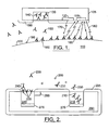
- FIG.1 is a schematic illustration of embodiments according to the present invention that can be used to determine antigen levels of in vivo tumor tissue 110.
- the tumor tissue 110 may be characterized by a type of tumor specific antigen (TSA) 195 located at the surface 100 of the tumor tissue 110.
- TSA tumor specific antigen
- a TSA 195 may be found on the surface of cell tissue 110.
- suitable biomolecules i.e. , TSAs
- suitable biomolecules indicative of tumor cell proliferation are essentially independent of many of the biological, physiological, and/or environmental properties that are found in solid tumors.
- TSAs tumor specific antigen
- the phase of the tumor tissue 110 may be detected based on a concentration level of the TSA 195 at the surface 100.
- a "growth" phase of the tumor may be characterized by relatively high concentrations of the TSA 195 and a "remission” phase may be characterized by relatively low concentrations of TSA 195.
- a platform 105 is located in vivo proximate to the tumor tissue 110 and may or may not become bio-fouled with a bio-fouling tissue 190 over time.
- the platform 105 carries a matrix material 140 that can include fluorescently labeled antibodies 130 that are suspended in the matrix material 140.
- the matrix material 140 can be soluble so that the fluorescently labeled antibodies 130 can be released from the matrix material 140 over time.
- the matrix material 140 can be in the shape of a cylinder as shown, for example, in FIGS. 3 and 4 . Other shapes may be used.
- the platform 105 can also include a telemetry system that transmits and receive signals to and from systems which are ex vivo.
- the fluorescently labeled antibodies 130 are selected to specifically interact or bind with the TSA 195 that characterizes the tumor tissue 110, but is not associated with normal tissue. More than one TSA 195 may characterize a the tumor tissue 110.
- the fluorescently labeled antibodies 130 are released from the matrix material 140, some of the fluorescently labeled antibodies 130 bind with the TSA 195 on the surface 100 proximate to the platform 105 to form a binding complex 160.
- the unbound fluorescently labeled antibodies 150 may dissipate over time to become remote from the platform 105.
- An optical radiation source 120 emits a first optical radiation 170 that excites the fluorescent labels of the binding complexes 160 to a higher energy state.
- the first optical radiation is emitted through a biofouling tissue 190.
- the fluorescent labels of the bound complexes emit a second optical radiation 180.
- the respective wavelengths of the first optical radiation 170 and the second optical 180 may be selected to promote penetration of the bio-fouling tissue 190.
- the optical radiation source can be, for example, a laser diode, a high power Light Emitting Diode (LED), or the like, as described further herein.
- An optical radiation detector 115 can detect the second optical radiation 180 through bio-fouling tissue 190 thereby avoiding some of the drawbacks associated with conventional techniques.
- a time interval between the emission of the first optical radiation 170 and detection of the second optical radiation 180 can be selected to allow the fluorescently labeled antibodies 130 to bind with the TSA 195 on the surface 100.
- the optical radiation detector 115 can be a photodiode or a phototransistor. Other devices as described further herein and/or known to those skilled in the art and may be also be used.
- the optical radiation detector 115 can include an optical absorption filter to reduce the effects of background noise.
- the optical radiation source 120 and the optical radiation detector 115 can be separated by a shield that reduces the amount of the first optical radiation 170 that reaches the optical radiation detector 115.
- the optical radiation detector 115 is located about 500 micrometers from the bound complexes 160.
- the optical radiation detector 115 includes a lens that collects and focuses the second optical radiation 180 so that the separation between the optical radiation detector 115 and the bound complexes 160 may be increased.
- the intensity of the second optical radiation 180 can be used to determine the concentration of the TSA 195.
- the TSA 195 that is proximate to the platform 105 may have fluorescently labeled antibodies 130 bound thereto. Accordingly, the fluorescent labels may emit the second optical radiation 180 after the excitation of the first optical radiation 170.
- FIG. 2 is a schematic illustration of embodiments according to the present invention.
- a platform 200 can be located in vivo proximate to tissue 290 that includes antigens 205.
- a bio-fouling tissue 225 may develop on portions of the platform 200 over time.
- the platform 200 can include first and second matrix materials 240 and 215, respectively.
- the first matrix material 240 can include unlabeled antibodies 220.
- the second matrix material 215 can include fluorescently labeled antibodies 210.
- additional matrix materials can be used.
- the matrix materials may include different concentrations of antibodies and/or mixtures of antibodies wherein some antibodies may be labeled and others may not be labeled.
- the unlabeled and fluorescently labeled antibodies 220, 210 can be released continuously over time or in phases as described herein.
- the release of the respective antibodies may be out of phase with respect to each other.
- unlabeled antibodies 220 may be released during a first time interval and the fluorescently labeled antibodies 210 may be released during a second time interval
- the antibodies may also be released using an apparatus 270 coupled to the respective matrix material, as described further herein.
- the apparatus 270 coupled to each matrix material may be different.
- the apparatus 270 may be used to control the rate of release of the unlabeled and/or labeled antibodies.
- the use of a controlled release strategy can be employed to provide a continuous source of fluorescently-labeled antibody 230, which can be advantageous in the dynamic biological environment in which the platform 200 must function.
- the unlabeled antibodies 220 are released into the tissue 290 to provide free unlabeled antibodies 235
- the fluorescently labeled antibodies 210 are released to provide free fluorescently labeled antibodies 230.
- Some of the free fluorescently labeled antibodies 230 bind to the antigens 205 to provide bound antigens 231.
- Some of the bound antigens 231 become bound to the unlabeled antibodies 220 at the surface of the first matrix material 240 to provide bound structures 290 at the surface of the first matrix material 240.
- An optical radiation emitter/detector 285 is adjacent to the first matrix material 240 and can be used to excite the bound structures 290 and detect a signal as discussed above.
- FIG. 3 is a schematic illustration of compositions of matter according to the present invention.
- fluorescently labeled antibodies 330 are released from a matrix material 335 over time.
- the matrix material can be selected based on factors such as biocompatibility, time release characteristics, degradation, interaction with the fluorescently labeled antibodies 330 suspended therein, lack of autofluorescence, etc.
- fluorescently labeled antibodies may be included in the matrix material 335 to provide a mixture of different types of antibodies.
- the term "different types of antibodies” will be understood to meant that one type of antibody may have more than kind of label, i.e. , label A and label B. Alternatively, more than one type of antibody (i.e. , antibody A and antibody B) may have the same label.
- the matrix material 335 can include type A and type B fluorescently labeled antibodies 330.
- the A and B type fluorescently labeled antibodies 330 may have different concentrations.
- the A type fluorescently labeled antibodies 330 can comprise 20% of the fluorescently labeled antibodies 330 and the type B fluorescently labeled antibodies 330 can comprise 80% of the fluorescently labeled antibodies 330. Additional types of fluorescently labeled antibodies 330 may also be included in varying concentrations.
- the matrix material 335 may comprise one or more of several polymers.
- the choice of polymer can be determined empirically as encapsulation, degradation and release characteristics of polymers in tissue may vary from subject to subject, or from cell type to cell type, or from sample to sample, and the like. Suitable biodegradable polymers can be based on hydrolysis of ester linkages in the polymer, and a variety of polymers of this type are commercially available and well characterized.
- the matrix material 335 is a mixture of different materials such as a combination of polylactic acid and polyglycolic acid.
- the different materials can occur in a range of concentrations.
- the matrix material 335 can comprise between about 0 and about 50% polylactic acid and/or between about 10 and about 50% polyglycolic acid.
- time release of the fluorescently labeled antibodies 330 may be controlled by selecting the matrix material 335 based on the biocompatibility of the material 335 with the antibody or biomolecule to be detected, polymer type, polymer structure ( e.g. , the physical size and porosity of the polymer release bead), the molecular weight of the matrix material 335, the porosity of the matrix material 335, and/or other material parameters.
- the matrix material 335 may be coupled to an apparatus 350 that can affect the rate at which the matrix material 335 releases the fluorescently labeled antibodies 330.
- the apparatus 350 can be a piezoelectric circuit that vibrates the matrix material 335, thereby causing the fluorescently labeled antibodies 330 to be released at varying rates.
- several parameters e.g ., polymer structure, molecular weight, porosity, etc.
- the polymer may be mounted on top of a piezoelectric element, whereby the actuation of the element (e.g.
- Another option for modulating release rate is to blend the matrix material 335 with an electrically conducting polymer (e.g ., polypyrrole) and, by oxidizing and reducing the polymer electrochemically, modulate the porosity of the blend ( Kontturi et al., "Polypyrrole as a model membrane for drug delivery", Journal of Electroanalytical Chemistry, 1998, 453(1-2), 231-238 , Hepel, M.
- an electrically conducting polymer e.g ., polypyrrole
- FIG. 4 is a schematic illustration of compositions of matter according to the present invention.
- fluorescently labeled antibodies 430 are released within the first, second, and third matrix material sections 435,440,445.
- the first and second matrix material sections 435,440 are separated by a first separator material 450 that can be devoid of the fluorescently labeled antibodies 430.
- the second and third matrix material sections 440,445 are separated by a second separator material 455 that can be devoid of the fluorescently labeled antibodies 430.
- the different matrix material sections can provide for "pulses" of labeled material to be released at different times. In particular, after a barrier dissolves, the underlying matrix section can provide for a pulsed release of the labeled antibody.
- first, second, and third matrix materials sections 435,440,445 can each have different compositions of fluorescently labeled antibodies 430 to provide different rates of release over time.
- FIG. 5 is a diagram that illustrates embodiments of in vivo circuits and systems according to the present invention.
- a matrix material 530 includes the fluorescently labeled antibodies that are released in a tissue 500 as described, for example, in reference to FIGs. 3 and 4 .
- the matrix material 530 can be coupled to an apparatus 580 that can vary the rate of release of the fluorescently labeled antibodies as described, for example, in reference to FIGs. 3 and 4 .
- An optical radiation source 505 can include an amplifier that responds to a control input A to provide an output current that passes through a high power light emitting diode that emits optical radiation 515.
- the optical radiation 515 can pass through a bio-fouling tissue 570 and excite the fluorescent labels on the fluorescently labeled antibodies.
- the excited fluorescent labels can emit an optical radiation 520 that can pass through the bio-fouling tissue 570 to reach an optical radiation detector 510.
- the optical radiation 520 impinges a photodetector.
- the photodetector can generate a current that can be converted to a voltage level that represents the level of the optical radiation 520.
- the photodetector is a photomultiplier.
- the optical radiation detector 510 can include an absorption filter to reduce background noise.
- the optical radiation source 505, the optical radiation detector 510, and the matrix material 530 can operate in conjunction with a processor circuit 525.
- the processor circuit 525 can control the release of the fluorescently labeled antibodies from the matrix material 530 by controlling the apparatus 580 that, for example, vibrates the matrix material 530 to vary the rate of release of the fluorescently labeled antibodies.
- the processor circuit 525 can provide an input to the optical radiation source 505.
- the processor circuit 525 can monitor an output signal C from the optical radiation source 505 to determine, for example, the power output thereof. Other functions may be monitored and/or controlled.
- the processor circuit 525 can receive a voltage level B from the optical radiation detector 510 to determine, for example, the intensity of the optical radiation 520.
- the processor can provide an output E to a telemetry system (526).
- the telemetry system 526 can transmit/receive data to/from an ex vivo system (not shown).
- the ex vivo system can control the release of the fluorescently labeled antibodies by transmitting a signal into the body for reception by the in vivo system.
- the in vivo system can release fluorescently labeled antibodies in response to the signal from the ex vivo system.
- Other signals can be transmitted from the ex vivo system.
- the transmitted/received data is digitally encoded. Other types of data transmission may be used.
- the in vivo system can transmit data to the ex vivo system.
- the in vivo system can transmit data associated with the intensity of the optical radiation 520.
- the in vivo system can transmit other data to the ex vivo system.
- the in vivo system can be implanted for in vivo use whereby the ex vivo system can control operations of the in vivo system including receiving data from the in vivo system without an associated invasive procedure.
- the in vivo system is powered remotely through the tissue in which it is implanted.
- the in vivo system can include an inductor that provides power to the in vivo system via an inductively coupled power signal from the ex vivo system.
- the in vivo system has a diameter of approximately 2 mm.
- a light emitting diode (LED) or laser diode (for greater excitation intensity) can be used as the excitation source and a photodiode can be used to detect the corresponding emission signal.
- Integral emission and absorption filters can be introduced as needed in the form of dielectric coatings on the diode elements.
- Light emitting diodes, and photodetectors are now commonly available. These devices can be extremely compact, with a laser diode being typically less than 100 pm. Thin film deposition and fiber optic technologies known to the skilled artisan permit the construction of extremely sharp optical filters.
- An external sensor package for the optical implant apparatus described above may be about 2 mm x 10 mm in the form of a rounded cylinder. This configuration may ease insertion into a subject when used in conjunction with a device similar to a biopsy needle.
- the standardization of package size and geometry may enable a diverse range of coatings such as diamond like carbon (DLC) or glasses of various compositions and plastics.
- the inner portion of the package can be used to provide a hermetic seal isolating the device from the effects of moisture and attack by the body.
- laser diodes are mounted on a heat sink and emit light from front and rear facets perpendicular to the circuit board.
- the optical power from the rear facet can be measured by a photodetector mounted on the opposite side of the circuit board. This permits feed back control of the optical power.
- a signal photodiode receives the return fluorescence or the absorption signal to be ratioed, as in the case of oxygen measurements.
- An optical rejection filter can be deposited on the photodetector to reduce background noise.
- the telemetry coil, drivers and other electronics can be distributed on either side of the circuit board.
- the embodiments of the invention described herein may afford effective baseline correction, a potentially important consideration in the practice of the present invention.
- Changes in diode laser output as a function of time can be accommodated through the use of standard photodiode feedback techniques. Measurements before and after insertion can be used to provide an initial baseline. This may be helpful in assessing background fluorescence and the degree of non-specific binding. The influence of external lighting as a parameter may also be assessed.
- the lifetime of the implant may be as long as six months or even more in some cases.
- One advantage of this detection scheme is that it may be relatively resistant to the accretion of material on the outer surface of the sensor ("biofouling").
- One aspect of the invention provides for emission and absorption wavelengths through whatever over layer covers the sensor surface. Although close proximity of the target fluorophore to the sensor is desirable, significant leeway is obtained for detection of signals away from the site of sensor implantation.
- one embodiment includes a time-released, tagged antibody or event-activated hybridization reaction. Continuous monitoring of the implanted sensor is possible so that kinetics of the reaction can also be assessed.
- a lens system may or may not be present, but the detector is preferably placed in close proximity (e.g., about 500 micrometers) to the source of fluorescence. In this way, the detector may become the image plane.
- the sensor may alternatively be non-imaging and accordingly may be used as a binary-state detector for the presence or absence of fluorescent signal.
- fluorescently labeled antibodies can be coupled to antigens associated with tumor cells.
- An optical radiation source can be used to excite the fluorescently labeled antibodies coupled to the antigens.
- the fluorescently labeled antibodies emit optical radiation in response to the excitation.
- a sensor can be used to detect a level of the optical radiation emitted by the fluorescently labeled antibodies.
- the level of optical radiation can be used to determine the concentration of antigens present on the surface of the tissue. The concentration of antigens may then be correlated to the proliferative state or growth behavior of the tissue.
Abstract
Description
- The present invention relates to the field of sensors, and more particularly, to biomolecular sensors.
- The ex vivo study of malignant cell populations has established some general principles by which clinical treatment protocols are developed. These principles have established differences between malignant and normal cell populations and have been employed in the treatment of malignant disease. There have been attempts to exploit these differences, both in pre-clinical and clinical studies, to obtain total tumor cell kills and improved cure rates.
- One of the major obstacles in achieving this goal has been the difficulty in minimizing normal tissue toxicity while increasing tumor cell kill (therapeutic index). Thus, some treatment strategies employ an empirical approach in the treatment of malignant disease. In particular, the time of delivery and dose of cytotoxic agents can be guided more by the response and toxicity to normal tissue than by the effects on the malignant cell population.
- Unfortunately, this approach may not provide accurate information on the changes during treatment of a malignant cell population. Making this information available may allow clinicians to exploit the differences between malignant and normal cells, and hence improve the treatment procedures.
- There have been a number of attempts to study changes that occur within a cell population. However, these attempts have not shown the ability to monitor the changes on a real time basis. Indeed, these methods typically provide information at one point in time and most are designed to provide information on one particular function or parameter. In addition, most of the conventional methods can be expensive as well as time consuming. This can be problematic for patients undergoing extended treatment periods typical of radiation and chemotherapy, especially when it is desirable to follow changes both during an active treatment and subsequent to the active treatment.
- In addition, tumors may have periods in which they are more susceptible to treatment by radiation or drug therapy. Providing a monitoring system which can continuously or semi-continuously monitor and potentially identify such a susceptible condition could provide increases in tumor destruction rates.
- Numerous tumor specific antigens (TSA) have been identified and antibodies specific for a number of these TSA's are known. For example, it has been demonstrated that sigma-2 receptors found on the surface of cells of the 9L rat brain tumor cell line, the mouse mammary adenocarcinoma lines 66 (diploid) and 67 (aneuploid), and the MCF-7 human breast tumor cell line may be markers of tumor cell proliferation. See Mach RH et al., Sigma 2 receptors as potential biomarkers of proliferation in breast cancer. Cancer Res 1997 Jan 1;57(1):156-61; Al-Nabulsi I et al., Effect of ploidy, recruitment, environmental factors, and tamoxifen treatment on the expression of sigma-2 receptors in proliferating and quiescent tumour cells. Br J Cancer 1999 Nov;81(6):925-33. Such markers may be amenable to detection by non-invasive imaging procedures. Accordingly, ligands that selectively bind sigma-2 receptors may be used to assess the proliferative status of tumors, although in vivo techniques utilizing such ligands have heretofore not been known. Although the field of tumor-specific treatment is still relatively unsettled, various researchers have proposed several potentially important techniques useful in such treatment. For example, the ex vivo detection of biomolecules can be useful in predicting the timing for advantageous treatment of tumors. Many of these techniques use a "hybridization event" to alter the physical or chemical properties associated with the biomolecules. The biomolecules having the altered property can be detected, for example, by optical or chemical means.
- One known technique for the detection of biomolecules, called Enzyme-Linked Immunosorbent Assay (ELISA), involves the detection of binding between a biomolecule and an enzyme-labeled antibody specific for the biomolecule. Other methods of detecting biomolecules utilize immunofluorescence, involving the use of a fluorescently labeled antibody to indicate the presence of the biomolecule. The in vivo use of these techniques may involve an invasive introduction of a sensor into the in vivo site to be analyzed. Moreover, these techniques may not be reliable if the surface where the sensor and the tissue interact is not clean. In particular, in vivo use can cause a sensor to become "bio-fouled" over time such that the operational properties of the sensor may change. In particular, proteins may begin to develop on the sensor within minutes of insertion of the sensor into the tissue, which may cause the sensor to operate improperly. In view of the foregoing, there remains a need for circuits, compositions of matter, and methods which can be used to, inter alia, detect biomolecular concentrations in vivo.
-
U.S. Patent No. 5,833,603 to Kovacs et al. relates to a biosensing transponder for implantation in an organism including a human which includes a biosensor for sensing one or more physical properties related to the organism after the device has been implanted.U.S. Patent No. 5,939,4532 to Heller et al. - According to an aspect of the present invention there is provided apparatus as defined by
claim 1. - Methods may include providing labeled antibodies in vivo to tissue having antigens that specifically bind the labeled antibody. A first optical radiation is emitted into the tissue in vivo to provide excite the labeled antibody bound to the antigen in vivo. A second optical radiation that is emitted by the excited labeled antibody in response to the excitation thereof can be detected in vivo. The labeled antibodies may be fluorescently labeled antibodies.
- The step of providing may include releasing the labeled antibodies in vivo from a matrix material over time. The step of providing may include releasing the labeled antibodies in vivo from a matrix material responsive to a control circuit located in vivo.
- The step of exciting may include emitting the first optical radiation through a bio-fouling tissue. The step of detecting can include detecting the second optical radiation through a bio-fouling tissue.
- Accordingly, labeled antibodies can bind antigens associated with tumor cells. A radiation source can be used to excite the labeled antibodies bound to the antigens. The labeled antibodies emit a second optical radiation in response to the excitation. A sensor can be used to detect a level of the optical radiation emitted by the labeled antibodies, The level of the second optical radiation can be used to determine the concentration of antigens present. The growth or proliferation of the tumor cells may be approximated from the concentration of antigen. The invention advantageously integrates the ability to probe fluorescently tagged entities with an implantable sensor platform, thus allowing accurate, real time deteriminations of antigen concentration in vivo.
-
-
FIG.1 is a schematic illustration of embodiments according to the present invention. -
FIG. 2 is a schematic illustration of embodiments according to the present invention. -
FIG. 3 is a schematic illustration of matrix compositions of matter according to the present invention. -
FIG. 4 is a schematic illustration of matrix compositions of matter according to the present invention. -
FIG. 5 is a circuit diagram that illustrates embodiments according to the present invention. - The present invention now will be described more fully hereinafter with reference to the accompanying drawings, in which preferred embodiments of the invention are shown. This invention may, however, be embodied in many different forms and should not be construed as limited to the embodiments set forth herein; rather, these embodiments are provided so that this disclosure will be thorough and complete, and will fully convey the scope of the invention to those skilled in the art. Like numbers refer to like elements throughout. In the figures, certain layers, regions, or components may be exaggerated or enlarged for clarity.
- The terminology used in the description of the invention herein is for the purpose of describing particular embodiments only and is not intended to be limiting of the invention. As used in the description of the invention and the appended claims, the singular forms "a", "an" and "the" are intended to include the plural forms as well, unless the context clearly indicates otherwise.
- Unless otherwise defined, all technical and scientific terms used herein have the same meaning as commonly understood by one of ordinary skill in the art to which this invention belongs. All publications, patent applications, patents, and other references mentioned herein are incorporated by reference in their entirety. The term "tissue," as used herein, can include cells, organs, bodily fluids, and other biological matter in a biological sample or the body of a subject. For example, the term tissue can be used to describe cells, organs and/or other biological matter in a human body. The term "biomolecule" can include tumor specific antigens (TSA), such as proteins associated with particular types of tumor cells. It will be understood that the present invention may be used for in vivo use or for ex vivo use. It will also be understood that the term "in vivo" is specifically intended to encompass in situ applications.
- In a preferred embodiment of the present invention, biomolecules (e.g., antigens) associated with hyperproliferative cells (including tumors, cancers, and neoplastic tissue, along with pre-malignant and non-neoplastic or non-malignant hyperproliferative cells) are detected. The term "tumor" is generally understood in the art to mean an abnormal mass of undifferentiated cells within a multicellular organism. Tumors can be malignant or benign. Preferably, embodiments of the inventions disclosed herein are used to detect biomolecules associated with malignant tumors. Examples of tumors, cancers, and neoplastic tissue associated with the biomolecules that can be detected by embodiments of the present invention include but are not limited to malignant tumors such as breast cancers; osteosarcomas; angiosarcomas; fibrosarcomas and other sarcomas; sinus tumors; ovarian, uretal, bladder, prostate and other genitourinary cancers; colon esophageal and stomach cancers and other gastrointestinal cancers; lung cancers; myelomas; pancreatic cancers; liver cancers; kidney cancers; endocrine cancers; skin cancers; and brain or central and peripheral nervous (CNS) system tumors, malignant or benign, including gliomas and neuroblastomas. Biomolecules associated with premalignant and non-neoplastic or non-malignant hyperproliferative tissue include but are not limited to biomolecules associated with myelodysplastic disorders; cervical carcinoma-in-situ; familial intestinal polyposes such as Gardner syndrome; oral leukoplakias; histiocytoses; keloids; hemangiomas; psoriasis; and cells made hyperproliferative by viral infections (e.g., warts).
- Although the present invention is described herein with reference to the detection of antigens associated with tumor and other hyperproliferative cells, the present invention may also be utilized for the measurement of glucose, cell necrosis byproducts, cell signaling proteins, and the like.
- The embodiments of the present invention are primarily concerned with use in human subjects, but the embodiments of the invention may also be used with animal subjects, particularly mammalian subjects such as primates, mice, rats, dogs, cats, livestock and horses for veterinary purposes, and for drug screening and drug development purposes.
- As used herein, the term "optical radiation" can include radiation that can be used to transmit signals in tissue, such as radiation in the visible, ultraviolet, infrared and/or other portions of the electromagnetic radiation spectrum.
- Although the embodiments described herein refer to fluorescently labeled binding molecules (i.e., antibodies), it will be understood that the present invention may be used with any type label, including fluorescent labels (e.g., fluorescein, rhodamine), radioactive labels (e.g., 35S, 125I, 131I), bioluminescent labels (e.g., biotin-streptavidin, green fluorescent protein (GFP)), and enzyme labels (e.g., horseradish peroxidase, alkaline phosphatase).
- It will also be understood that while embodiments described herein refer specifically to antibodies, the present invention may also be used with other molecules that bind the biomolecules to be detected. Furthermore, although the present invention is described with reference to detecting concentrations of antigens, the present invention may also be used to detect the concentration of any biomolecules whose detention is desired, including but not limited to proteins, polypeptides, nucleic acids, polysaccharides, and the like.
- As used herein, the term "antibody" is understood to encompass all antibodies as that term is understood in the art, including but not limited to polyclonal, monoclonal, chimeric, and single chain antibodies, Fab fragments, and fragments produced by a Fab expression library. Monoclonal antibodies may be prepared using any technique which provides for the production of antibody molecules by continuous cell lines in culture. These include, but are not limited to, the hybridoma technique, the human B-cell hybridoma technique, and the EBV-hybridoma technique. See, e.g., G. Kohler et.al. (1975) Nature 256, 495-497; D. Kozbor et al. (1985) J. Immunol. Methods 81, 31-42; R. J. Cote et al. (1983) Proc. Natl. Acad. Sci. USA 80, 2026-2030; and S. P. Cole et al.(1984) Mol. Cell Biol. 62,109-120.
- Chimeric antibodies may be produced according to methods set forth in, for example, S. L. Morrison et al. (1984) Proc. Natl. Acad. Sci. 81, 6851-6855; M. S. Neuberger et al. (1984) Nature 312, 604-608; and S. Takeda et al. (1985) Nature 314, 452-454). Alternatively, techniques described for the production of single chain antibodies may be adapted, using methods known in the art, to produce antigen-specific single chain antibodies. Antibodies may also be produced by inducing in vivo production in the lymphocyte population or by screening immunoglobulin libraries or panels of highly specific binding reagents as disclosed in the literature. See, e.g., R. Orlandi et al. (1989) Proc. Natl. Acad. Sci, 86, 3833-3837; and G. Winter et al. (1991) Nature 349,293-299. Antibodies with related specificity, but of distinct idiotypic composition, may be generated by chain shuffling from random combinatorial immunoglobulin libraries. See e.g., D. R. Burton (1991) Proc. Natl. Acad. Sci. 88,11120-11123).
- Antibody fragments which contain specific binding sites for antigens can also be used. For example, such fragment include, but are not limited to, the F(ab')2 fragments which can be produced by pepsin digestion of the antibody molecule and the Fab fragments which can be generated by reducing the disulfide bridges of the F(ab')2 fragments. Alternatively, Fab expression libraries may be constructed to allow rapid and easy identification of monoclonal Fab fragments with the desired specificity. See W. D. Huse et al. (1989) Science 254,1275-1281.
- Fluorescence-based assays are well established for ex vivo studies and a number of fluorophores and tagged antibody systems are commercially available. An extensive list of commercially available pH-dependent fluorophores useful in the practice of the present invention can be found in R. P. Haugland, Chapter 23 ("pH Indicators") of Handbook of Fluorescent Probes and Research Chemicals, Sixth Edition (Molecular Probes, Inc. Eugene, Oregon, (1996), and HTML version located at www.probes.com).
- According to embodiments of the present invention, fluorescently labeled binding molecules, such as antibodies, can be bound to biomolecules, such as antigens, associated with tumor cells. An optical radiation source can be used to excite the fluorescently labeled antibodies bound to the antigens. The fluorescently labeled antibodies emit a second optical radiation in response to the excitation. A sensor can be used to detect a level of the optical radiation emitted by the fluorescently labeled antibodies. The level of emitted optical radiation can be used to determine the concentration of antigens present. The concentration of antigen may then be correlated to the amount, or the presence, or the growth or proliferation behavior of the tumor cells based on known relationships between concentration of tumor specific antigen and these parameters, or according to relationships that may be determined by the skilled artisan.
-
FIG.1 is a schematic illustration of embodiments according to the present invention that can be used to determine antigen levels of invivo tumor tissue 110. Thetumor tissue 110 may be characterized by a type of tumor specific antigen (TSA) 195 located at thesurface 100 of thetumor tissue 110. For example, aTSA 195 may be found on the surface ofcell tissue 110. In general, suitable biomolecules (i.e., TSAs) indicative of tumor cell proliferation are essentially independent of many of the biological, physiological, and/or environmental properties that are found in solid tumors. Although only a single surface oftissue 110 is shown, it will be understood that embodiments according to the present invention may be utilized to detect biomolecule concentrations for a plurality oftissue 110. - The phase of the
tumor tissue 110 may be detected based on a concentration level of theTSA 195 at thesurface 100. For example, a "growth" phase of the tumor may be characterized by relatively high concentrations of theTSA 195 and a "remission" phase may be characterized by relatively low concentrations ofTSA 195. - A
platform 105 is located in vivo proximate to thetumor tissue 110 and may or may not become bio-fouled with abio-fouling tissue 190 over time. Theplatform 105 carries amatrix material 140 that can include fluorescently labeledantibodies 130 that are suspended in thematrix material 140. Thematrix material 140 can be soluble so that the fluorescently labeledantibodies 130 can be released from thematrix material 140 over time. Thematrix material 140 can be in the shape of a cylinder as shown, for example, inFIGS. 3 and4 . Other shapes may be used. Theplatform 105 can also include a telemetry system that transmits and receive signals to and from systems which are ex vivo. - The fluorescently labeled
antibodies 130 are selected to specifically interact or bind with theTSA 195 that characterizes thetumor tissue 110, but is not associated with normal tissue. More than oneTSA 195 may characterize a thetumor tissue 110. When the fluorescently labeledantibodies 130 are released from thematrix material 140, some of the fluorescently labeledantibodies 130 bind with theTSA 195 on thesurface 100 proximate to theplatform 105 to form a bindingcomplex 160. The unbound fluorescently labeledantibodies 150 may dissipate over time to become remote from theplatform 105. - An optical radiation source 120 emits a first
optical radiation 170 that excites the fluorescent labels of thebinding complexes 160 to a higher energy state. In one embodiment of the invention, the first optical radiation is emitted through abiofouling tissue 190. Once excited, the fluorescent labels of the bound complexes emit a secondoptical radiation 180. The respective wavelengths of the firstoptical radiation 170 and the second optical 180 may be selected to promote penetration of thebio-fouling tissue 190. The optical radiation source can be, for example, a laser diode, a high power Light Emitting Diode (LED), or the like, as described further herein. - An optical radiation detector 115 can detect the second
optical radiation 180 throughbio-fouling tissue 190 thereby avoiding some of the drawbacks associated with conventional techniques. A time interval between the emission of the firstoptical radiation 170 and detection of the secondoptical radiation 180 can be selected to allow the fluorescently labeledantibodies 130 to bind with theTSA 195 on thesurface 100. The optical radiation detector 115 can be a photodiode or a phototransistor. Other devices as described further herein and/or known to those skilled in the art and may be also be used. - The optical radiation detector 115 can include an optical absorption filter to reduce the effects of background noise. The optical radiation source 120 and the optical radiation detector 115 can be separated by a shield that reduces the amount of the first
optical radiation 170 that reaches the optical radiation detector 115. In some embodiments, the optical radiation detector 115 is located about 500 micrometers from the boundcomplexes 160. In other embodiments, the optical radiation detector 115 includes a lens that collects and focuses the secondoptical radiation 180 so that the separation between the optical radiation detector 115 and the boundcomplexes 160 may be increased. - The intensity of the second
optical radiation 180 can be used to determine the concentration of theTSA 195. In particular, theTSA 195 that is proximate to theplatform 105 may have fluorescently labeledantibodies 130 bound thereto. Accordingly, the fluorescent labels may emit the secondoptical radiation 180 after the excitation of the firstoptical radiation 170. -
FIG. 2 is a schematic illustration of embodiments according to the present invention. According toFIG. 2 , aplatform 200 can be located in vivo proximate totissue 290 that includesantigens 205. Abio-fouling tissue 225 may develop on portions of theplatform 200 over time. Theplatform 200 can include first andsecond matrix materials first matrix material 240 can includeunlabeled antibodies 220. Thesecond matrix material 215 can include fluorescently labeledantibodies 210. In some embodiments, additional matrix materials can be used. As described herein, the matrix materials may include different concentrations of antibodies and/or mixtures of antibodies wherein some antibodies may be labeled and others may not be labeled. - The unlabeled and fluorescently labeled
antibodies unlabeled antibodies 220 may be released during a first time interval and the fluorescently labeledantibodies 210 may be released during a second time interval, The antibodies may also be released using anapparatus 270 coupled to the respective matrix material, as described further herein. Theapparatus 270 coupled to each matrix material may be different. In some embodiments, theapparatus 270 may be used to control the rate of release of the unlabeled and/or labeled antibodies. The use of a controlled release strategy can be employed to provide a continuous source of fluorescently-labeledantibody 230, which can be advantageous in the dynamic biological environment in which theplatform 200 must function. - The
unlabeled antibodies 220 are released into thetissue 290 to provide freeunlabeled antibodies 235, The fluorescently labeledantibodies 210 are released to provide free fluorescently labeledantibodies 230. Some of the free fluorescently labeledantibodies 230 bind to theantigens 205 to provide boundantigens 231. Some of the boundantigens 231 become bound to theunlabeled antibodies 220 at the surface of thefirst matrix material 240 to provide boundstructures 290 at the surface of thefirst matrix material 240. An optical radiation emitter/detector 285 is adjacent to thefirst matrix material 240 and can be used to excite the boundstructures 290 and detect a signal as discussed above. -
FIG. 3 is a schematic illustration of compositions of matter according to the present invention. According toFIG. 3 , fluorescently labeledantibodies 330 are released from amatrix material 335 over time. The matrix material can be selected based on factors such as biocompatibility, time release characteristics, degradation, interaction with the fluorescently labeledantibodies 330 suspended therein, lack of autofluorescence, etc. - It will be understood that other fluorescently labeled antibodies may be included in the
matrix material 335 to provide a mixture of different types of antibodies. The term "different types of antibodies" will be understood to meant that one type of antibody may have more than kind of label, i.e., label A and label B. Alternatively, more than one type of antibody (i.e., antibody A and antibody B) may have the same label. For example, thematrix material 335 can include type A and type B fluorescently labeledantibodies 330. Moreover, the A and B type fluorescently labeledantibodies 330 may have different concentrations. For example, the A type fluorescently labeledantibodies 330 can comprise 20% of the fluorescently labeledantibodies 330 and the type B fluorescently labeledantibodies 330 can comprise 80% of the fluorescently labeledantibodies 330. Additional types of fluorescently labeledantibodies 330 may also be included in varying concentrations. - It is preferable that the
matrix material 335 not react with or damage the fluorescently labeledantibodies 330 suspended therein. It is also preferable that thematrix material 335 not promote bio-fouling at the interaction surface 340 so that the fluorescently labeledantibodies 330 may be released over time without undue interference. Thematrix material 335 may comprise one or more of several polymers. The choice of polymer can be determined empirically as encapsulation, degradation and release characteristics of polymers in tissue may vary from subject to subject, or from cell type to cell type, or from sample to sample, and the like. Suitable biodegradable polymers can be based on hydrolysis of ester linkages in the polymer, and a variety of polymers of this type are commercially available and well characterized. Many of these polymers degrade into small, non-toxic molecules. Some of the most common biodegradable polymers are poly(lactic acid) and poly(glycolic acid). Fried, Joel R. Polymer Science and Technology, Englewood Cliffs, NJ, Prentice Hall, 1995, pp. 246-249. In some embodiments according to the present invention, thematrix material 335 is a mixture of different materials such as a combination of polylactic acid and polyglycolic acid. The different materials can occur in a range of concentrations. For example, thematrix material 335 can comprise between about 0 and about 50% polylactic acid and/or between about 10 and about 50% polyglycolic acid. - In some embodiments, time release of the fluorescently labeled
antibodies 330 may be controlled by selecting thematrix material 335 based on the biocompatibility of the material 335 with the antibody or biomolecule to be detected, polymer type, polymer structure (e.g., the physical size and porosity of the polymer release bead), the molecular weight of thematrix material 335, the porosity of thematrix material 335, and/or other material parameters. - In other embodiments, the
matrix material 335 may be coupled to anapparatus 350 that can affect the rate at which thematrix material 335 releases the fluorescently labeledantibodies 330. For example, theapparatus 350 can be a piezoelectric circuit that vibrates thematrix material 335, thereby causing the fluorescently labeledantibodies 330 to be released at varying rates. Although several parameters (e.g., polymer structure, molecular weight, porosity, etc.) are available to control the rate and time course of release, other techniques for controlling release may be used. For example, the polymer may be mounted on top of a piezoelectric element, whereby the actuation of the element (e.g., mechanically shaking the polymer with a sinusoidal input to the piezoelectric) increases the rate of release. Another option for modulating release rate is to blend thematrix material 335 with an electrically conducting polymer (e.g., polypyrrole) and, by oxidizing and reducing the polymer electrochemically, modulate the porosity of the blend (Kontturi et al., "Polypyrrole as a model membrane for drug delivery", Journal of Electroanalytical Chemistry, 1998, 453(1-2), 231-238, Hepel, M. et al., "Application of the electrochemical quartz crystal microbalance for electrochemically controlled binding and release of chlorpromazine from conductive polymer matrix", Microchemical Journal, 1997, 56, 54-64, Yano, S. et al., "Extracellular release of a recombinant gene product by osmotic shock from immobilized microalga in electroconductive membrane" Bioelectrochemistry and Bioenergetics, 1996, 39, 89-93, Bidan et al., "Incorporation of Sulfonated Cyclodextrins into Polypyrrole - An Approach for the Electro-controlled delivering of Neutral-Drugs", Biosensors & Bioelectronics, 1995, 10, 219-229, Hepel, M. et al., "Electrorelease of Drugs from Composite Polymer-Films" ACS Symposium Series, 1994, 545, 79-97. -
FIG. 4 is a schematic illustration of compositions of matter according to the present invention. According toFIG. 4 , fluorescently labeledantibodies 430 are released within the first, second, and third matrix material sections 435,440,445. The first and second matrix material sections 435,440 are separated by afirst separator material 450 that can be devoid of the fluorescently labeledantibodies 430. The second and third matrix material sections 440,445 are separated by asecond separator material 455 that can be devoid of the fluorescently labeledantibodies 430. The different matrix material sections can provide for "pulses" of labeled material to be released at different times. In particular, after a barrier dissolves, the underlying matrix section can provide for a pulsed release of the labeled antibody. This could be used, for example, to measure a level of antigen expression over time. Moreover, the first, second, and third matrix materials sections 435,440,445 can each have different compositions of fluorescently labeledantibodies 430 to provide different rates of release over time. -
FIG. 5 is a diagram that illustrates embodiments of in vivo circuits and systems according to the present invention. Amatrix material 530 includes the fluorescently labeled antibodies that are released in atissue 500 as described, for example, in reference toFIGs. 3 and4 . Thematrix material 530 can be coupled to anapparatus 580 that can vary the rate of release of the fluorescently labeled antibodies as described, for example, in reference toFIGs. 3 and4 . - An
optical radiation source 505 can include an amplifier that responds to a control input A to provide an output current that passes through a high power light emitting diode that emitsoptical radiation 515. Theoptical radiation 515 can pass through abio-fouling tissue 570 and excite the fluorescent labels on the fluorescently labeled antibodies. - The excited fluorescent labels can emit an
optical radiation 520 that can pass through thebio-fouling tissue 570 to reach anoptical radiation detector 510. For example, theoptical radiation 520 impinges a photodetector. In response, the photodetector can generate a current that can be converted to a voltage level that represents the level of theoptical radiation 520. In some embodiments according to the present invention, the photodetector is a photomultiplier. Theoptical radiation detector 510 can include an absorption filter to reduce background noise. - The
optical radiation source 505, theoptical radiation detector 510, and thematrix material 530 can operate in conjunction with aprocessor circuit 525. Theprocessor circuit 525 can control the release of the fluorescently labeled antibodies from thematrix material 530 by controlling theapparatus 580 that, for example, vibrates thematrix material 530 to vary the rate of release of the fluorescently labeled antibodies. - The
processor circuit 525 can provide an input to theoptical radiation source 505. Theprocessor circuit 525 can monitor an output signal C from theoptical radiation source 505 to determine, for example, the power output thereof. Other functions may be monitored and/or controlled. - The
processor circuit 525 can receive a voltage level B from theoptical radiation detector 510 to determine, for example, the intensity of theoptical radiation 520. The processor can provide an output E to a telemetry system (526). Thetelemetry system 526 can transmit/receive data to/from an ex vivo system (not shown). The ex vivo system can control the release of the fluorescently labeled antibodies by transmitting a signal into the body for reception by the in vivo system. The in vivo system can release fluorescently labeled antibodies in response to the signal from the ex vivo system. Other signals can be transmitted from the ex vivo system. In some embodiments, the transmitted/received data is digitally encoded. Other types of data transmission may be used. - The in vivo system can transmit data to the ex vivo system. For example, the in vivo system can transmit data associated with the intensity of the
optical radiation 520. The in vivo system can transmit other data to the ex vivo system. Accordingly, the in vivo system can be implanted for in vivo use whereby the ex vivo system can control operations of the in vivo system including receiving data from the in vivo system without an associated invasive procedure. - In some embodiments, the in vivo system is powered remotely through the tissue in which it is implanted. For example, the in vivo system can include an inductor that provides power to the in vivo system via an inductively coupled power signal from the ex vivo system. In some embodiments, the in vivo system has a diameter of approximately 2 mm.
- In the embodiments of the invention described above, a light emitting diode (LED) or laser diode (for greater excitation intensity) can be used as the excitation source and a photodiode can be used to detect the corresponding emission signal. Integral emission and absorption filters can be introduced as needed in the form of dielectric coatings on the diode elements. Light emitting diodes, and photodetectors are now commonly available. These devices can be extremely compact, with a laser diode being typically less than 100 pm. Thin film deposition and fiber optic technologies known to the skilled artisan permit the construction of extremely sharp optical filters.
- An external sensor package for the optical implant apparatus described above may be about 2 mm x 10 mm in the form of a rounded cylinder. This configuration may ease insertion into a subject when used in conjunction with a device similar to a biopsy needle. The standardization of package size and geometry may enable a diverse range of coatings such as diamond like carbon (DLC) or glasses of various compositions and plastics. The inner portion of the package can be used to provide a hermetic seal isolating the device from the effects of moisture and attack by the body.
- In some embodiments, laser diodes are mounted on a heat sink and emit light from front and rear facets perpendicular to the circuit board. The optical power from the rear facet can be measured by a photodetector mounted on the opposite side of the circuit board. This permits feed back control of the optical power. On one side of the optical barrier dividing the cylinder, a signal photodiode receives the return fluorescence or the absorption signal to be ratioed, as in the case of oxygen measurements. An optical rejection filter can be deposited on the photodetector to reduce background noise. The telemetry coil, drivers and other electronics can be distributed on either side of the circuit board.
- The embodiments of the invention described herein may afford effective baseline correction, a potentially important consideration in the practice of the present invention. Changes in diode laser output as a function of time can be accommodated through the use of standard photodiode feedback techniques. Measurements before and after insertion can be used to provide an initial baseline. This may be helpful in assessing background fluorescence and the degree of non-specific binding. The influence of external lighting as a parameter may also be assessed. The lifetime of the implant may be as long as six months or even more in some cases.
- One advantage of this detection scheme is that it may be relatively resistant to the accretion of material on the outer surface of the sensor ("biofouling"). One aspect of the invention provides for emission and absorption wavelengths through whatever over layer covers the sensor surface. Although close proximity of the target fluorophore to the sensor is desirable, significant leeway is obtained for detection of signals away from the site of sensor implantation. As discussed herein, one embodiment includes a time-released, tagged antibody or event-activated hybridization reaction. Continuous monitoring of the implanted sensor is possible so that kinetics of the reaction can also be assessed.
- In embodiments of the present invention, a lens system may or may not be present, but the detector is preferably placed in close proximity (e.g., about 500 micrometers) to the source of fluorescence. In this way, the detector may become the image plane. The sensor may alternatively be non-imaging and accordingly may be used as a binary-state detector for the presence or absence of fluorescent signal.
- As disclosed above, according to embodiments of the present invention, fluorescently labeled antibodies can be coupled to antigens associated with tumor cells. An optical radiation source can be used to excite the fluorescently labeled antibodies coupled to the antigens. The fluorescently labeled antibodies emit optical radiation in response to the excitation. A sensor can be used to detect a level of the optical radiation emitted by the fluorescently labeled antibodies. The level of optical radiation can be used to determine the concentration of antigens present on the surface of the tissue. The concentration of antigens may then be correlated to the proliferative state or growth behavior of the tissue.
Claims (18)
- An implantable apparatus comprising:an optical radiation source (120, 285, 505) configured for in vivo use to emit first optical radiation (170, 515);an optical radiation detector (115, 285) configured for in vivo use to detect second optical radiation (180, 510) ;a processor circuit (525), coupled to the optical radiation source and the optical radiation detector, that controls the release, from the apparatus, of fluorescently labelled antibodies (130, 210, 330, 430) for binding with predetermined tumour specific antigens (195, 205) to form local fluorescently labelled binding complexes (160, 231),and that controls the emission of the first optical radiation to excite the local fluorescently labelled binding complexes,and that receives an intensity signal as a voltage level associated with an intensity of second optical radiation emitted by the excited local fluorescently labelled binding complexes,and that transmits a signal associated with the intensity of the second optical radiation to an ex vivo system,
wherein a time interval between the emission of the first optical radiation and detection of the second optical radiation can be selected to allow the fluorescently labelled antibodies to bind with the tumour specific antigens to form the local fluorescently labelled binding complexes and allow unbound fluorescently labelled antibodies to dissipate remote from the apparatus. - An apparatus according to claim 1 further comprising:a supply of the fluorescently labelled binding molecules configured to be excited by the first optical radiation, the supply being encapsulated by a material (140, 215, 335, 435, 440, 445) that dissolves over time to release the fluorescently labelled binding molecules in vivo proximate to the target biomolecules to which the fluorescently labelled binding molecules are configured to bind.
- An apparatus according to claims 1 or 2, wherein the fluorescently labelled antibodies are selected to bind to the tumour specific antigens but not antigens associated with normal tissue.
- An apparatus according to claim 1, wherein the biomolecule is a sigma-2 receptor.
- An apparatus according to claim 1, wherein the optical radiation source emits the first optical radiation through a bio-fouling tissue (190, 225, 570).
- An apparatus according to claim 1, wherein the optical radiation detector detects the second optical radiation through a bio-fouling tissue.
- An apparatus according to claim 1, wherein the optical radiation source is selected from a group consisting of a high powered LED and a laser.
- An apparatus according to claim 1, wherein the optical radiation detector is selected from a group consisting of a phototransistor, a photodiode, and a photomultiplier.
- An apparatus according to claim 1, wherein the first optical radiation has a first frequency and the second optical radiation has a second frequency.
- An apparatus according to claim 9, wherein the first frequency is greater than the second frequency.
- An apparatus according to claim 1 further comprising:an emission filter coupled to the optical radiation source; andan absorption filter coupled to the optical radiation detector.
- An apparatus according to claim 1, further comprising:an inductor coupled to the processor circuit, wherein the inductor provides power to the circuit in response to a power signal received from the ex vivo system.
- An apparatus according to claim 1, further comprising a platform (105) having a diameter of about 2.0 mm, wherein the processor circuit is provided on the platform.
- An apparatus according to claim 12, wherein the signal is digitally encoded via the inductor.
- An apparatus according to claim 2, wherein the supply of the fluorescently labelled antibodies comprises:first and second portions that include the fluorescently labelled antibodies; anda separator portion that separates the first portion from the second portion.
- An apparatus according to claim 15, wherein the separator portion is less soluble in tissue than the first and second portions.
- An apparatus according to claim 15, wherein the first and second portions include first and second fluorescently labelled antigens that are molecules of different compositions.
- An apparatus according to claim 3, wherein the fluorescently labelled antigens are located on a platform with the optical radiation source, the optical radiation detector, and the processor circuit.
Applications Claiming Priority (3)
| Application Number | Priority Date | Filing Date | Title |
|---|---|---|---|
| US24757400P | 2000-11-09 | 2000-11-09 | |
| US247574P | 2000-11-09 | ||
| PCT/US2001/047373 WO2002039112A2 (en) | 2000-11-09 | 2001-11-07 | In vivo detection of biomolecule concentrations using fluorescent tags |
Publications (2)
| Publication Number | Publication Date |
|---|---|
| EP1332364A2 EP1332364A2 (en) | 2003-08-06 |
| EP1332364B1 true EP1332364B1 (en) | 2009-08-26 |
Family
ID=22935419
Family Applications (1)
| Application Number | Title | Priority Date | Filing Date |
|---|---|---|---|
| EP01986125A Expired - Lifetime EP1332364B1 (en) | 2000-11-09 | 2001-11-07 | In vivo detection of biomolecule concentrations using fluorescent tags |
Country Status (8)
| Country | Link |
|---|---|
| US (3) | US7378056B2 (en) |
| EP (1) | EP1332364B1 (en) |
| JP (1) | JP3981328B2 (en) |
| AT (1) | ATE441110T1 (en) |
| AU (2) | AU2002236590B2 (en) |
| CA (1) | CA2429127A1 (en) |
| DE (1) | DE60139705D1 (en) |
| WO (1) | WO2002039112A2 (en) |
Families Citing this family (19)
| Publication number | Priority date | Publication date | Assignee | Title |
|---|---|---|---|---|
| JP4607859B2 (en) * | 2003-02-19 | 2011-01-05 | サイセル・テクノロジーズ,インコーポレイテッド | In vivo fluorescent sensor, system and related methods operating in conjunction with a fluorescent analyte |
| JP4733918B2 (en) | 2003-10-01 | 2011-07-27 | オリンパス株式会社 | Capsule dosing system |
| CN100428912C (en) * | 2004-03-25 | 2008-10-29 | 奥林巴斯株式会社 | In-vivo information acquisition apparatus and in-vivo information acquisition apparatus system |
| US20060027756A1 (en) * | 2004-08-09 | 2006-02-09 | Ian Thomson | Dosimeter having an array of sensors for measuring ionizing radiation, and dosimetry system and method using such a dosimeter |
| US7415482B2 (en) * | 2005-02-11 | 2008-08-19 | Rivet Software, Inc. | XBRL enabler for business documents |
| US20060270919A1 (en) * | 2005-05-11 | 2006-11-30 | Mytek, Llc | Biomarkers sensing |
| GB0712109D0 (en) * | 2007-06-22 | 2007-08-01 | Edinburgh Instr | Fluorescence lifetime and fluorescence assays |
| EP2095762B1 (en) * | 2008-02-26 | 2011-05-11 | Biostems Ltd. | Device for in vivo micro-invasive investigation comprising a metal guide |
| CA2891990C (en) | 2008-05-20 | 2022-07-26 | Ralph Sebastian Dacosta | Device and method for fluorescence-based imaging and monitoring |
| US20100249550A1 (en) * | 2009-03-25 | 2010-09-30 | Neilcor Puritan Bennett LLC | Method And Apparatus For Optical Filtering Of A Broadband Emitter In A Medical Sensor |
| US11861696B1 (en) | 2013-02-14 | 2024-01-02 | Capital Confirmation, Inc. | Systems and methods for obtaining accountant prepared financial statement confirmation |
| DK3171765T3 (en) | 2014-07-24 | 2021-11-01 | Univ Health Network | COLLECTION AND ANALYSIS OF DATA FOR DIAGNOSTIC PURPOSES |
| US11013436B2 (en) | 2017-09-06 | 2021-05-25 | Medtronic, Inc. | Marker monitoring via a medical device |
| WO2019060298A1 (en) | 2017-09-19 | 2019-03-28 | Neuroenhancement Lab, LLC | Method and apparatus for neuroenhancement |
| US11717686B2 (en) | 2017-12-04 | 2023-08-08 | Neuroenhancement Lab, LLC | Method and apparatus for neuroenhancement to facilitate learning and performance |
| WO2019133997A1 (en) | 2017-12-31 | 2019-07-04 | Neuroenhancement Lab, LLC | System and method for neuroenhancement to enhance emotional response |
| US11364361B2 (en) | 2018-04-20 | 2022-06-21 | Neuroenhancement Lab, LLC | System and method for inducing sleep by transplanting mental states |
| EP3849410A4 (en) | 2018-09-14 | 2022-11-02 | Neuroenhancement Lab, LLC | System and method of improving sleep |
| US11786694B2 (en) | 2019-05-24 | 2023-10-17 | NeuroLight, Inc. | Device, method, and app for facilitating sleep |
Family Cites Families (152)
| Publication number | Priority date | Publication date | Assignee | Title |
|---|---|---|---|---|
| JPS36022343B1 (en) | 1959-12-24 | 1961-11-18 | Univ Tokyo | |
| US3638640A (en) | 1967-11-01 | 1972-02-01 | Robert F Shaw | Oximeter and method for in vivo determination of oxygen saturation in blood using three or more different wavelengths |
| US3972320A (en) | 1974-08-12 | 1976-08-03 | Gabor Ujhelyi Kalman | Patient monitoring system |
| US4163380A (en) | 1977-10-11 | 1979-08-07 | Lockheed Corporation | Forming of preconsolidated metal matrix composites |
| USRE32361E (en) | 1979-05-14 | 1987-02-24 | Medtronic, Inc. | Implantable telemetry transmission system for analog and digital data |
| US4326535A (en) | 1980-05-13 | 1982-04-27 | Akron City Hospital | Circuit and method for the radiotelemetry of esophageal pH in an ECG radiotelemetry system |
| US4494545A (en) | 1980-05-27 | 1985-01-22 | Cordis Corporation | Implant telemetry system |
| US4361153A (en) | 1980-05-27 | 1982-11-30 | Cordis Corporation | Implant telemetry system |
| US4556063A (en) | 1980-10-07 | 1985-12-03 | Medtronic, Inc. | Telemetry system for a medical device |
| US4523279A (en) | 1980-11-24 | 1985-06-11 | Oximetrix, Inc. | Apparatus for determining oxygen saturation levels in blood |
| US4397313A (en) | 1981-08-03 | 1983-08-09 | Clini-Therm Corporation | Multiple microwave applicator system and method for microwave hyperthermia treatment |
| US4397314A (en) | 1981-08-03 | 1983-08-09 | Clini-Therm Corporation | Method and apparatus for controlling and optimizing the heating pattern for a hyperthermia system |
| US4416283A (en) | 1981-08-31 | 1983-11-22 | Cordis Corporation | Programming and telemetry system for biomedical implantable device |
| CA1188431A (en) | 1981-10-02 | 1985-06-04 | Canadian Astronautics Limited | Direct reading dosimeter |
| US4431004A (en) | 1981-10-27 | 1984-02-14 | Bessman Samuel P | Implantable glucose sensor |
| US5186172A (en) | 1982-03-22 | 1993-02-16 | Mountpelier Investments, S.A. | Remote sensing tonometric catheter apparatus |
| US4571292A (en) | 1982-08-12 | 1986-02-18 | Case Western Reserve University | Apparatus for electrochemical measurements |
| US4571589A (en) | 1982-11-22 | 1986-02-18 | Cordis Corporation | Biomedical implant with high speed, low power two-way telemetry |
| US4961422A (en) | 1983-01-21 | 1990-10-09 | Marchosky J Alexander | Method and apparatus for volumetric interstitial conductive hyperthermia |
| AU577519B2 (en) | 1983-01-21 | 1988-09-29 | Jose A. Marchosky | Implantable hyperthermia device and system |
| US4575676A (en) | 1983-04-04 | 1986-03-11 | Advanced Research And Applications Corporation | Method and apparatus for radiation testing of electron devices |
| GB2140563B (en) | 1983-04-27 | 1987-03-04 | Critikon Inc | Method and apparatus for zero calibration of oxygen-sensing polarographic devices |
| US4543953A (en) | 1983-07-18 | 1985-10-01 | Cordis Corporation | Analog telemetry system for biomedical implant |
| US4655880A (en) | 1983-08-01 | 1987-04-07 | Case Western Reserve University | Apparatus and method for sensing species, substances and substrates using oxidase |
| US4519401A (en) | 1983-09-20 | 1985-05-28 | Case Western Reserve University | Pressure telemetry implant |
| FI68734C (en) | 1983-11-11 | 1985-10-10 | Seppo Saeynaejaekangas | FOER FARAND FOR ORORDING FOR TELEMETRIC MAINTENANCE AV HANDLING FOR ECG SIGNAL WITH ANALYTICAL AV ETT MAGNETISKT NAERFAELT |
| GB8422876D0 (en) | 1984-09-11 | 1984-10-17 | Secr Defence | Silicon implant devices |
| US4638436A (en) | 1984-09-24 | 1987-01-20 | Labthermics Technologies, Inc. | Temperature control and analysis system for hyperthermia treatment |
| US4681111A (en) | 1985-04-05 | 1987-07-21 | Siemens-Pacesetter, Inc. | Analog and digital telemetry system for an implantable device |
| US4651741A (en) | 1985-05-30 | 1987-03-24 | Baxter Travenol Laboratories, Inc. | Method and apparatus for determining oxygen saturation in vivo |
| US5012411A (en) | 1985-07-23 | 1991-04-30 | Charles J. Policastro | Apparatus for monitoring, storing and transmitting detected physiological information |
| CA1204885A (en) | 1985-09-18 | 1986-05-20 | Thomson & Nielson Electronics Ltd. | Dosimeter |
| US4703756A (en) | 1986-05-06 | 1987-11-03 | The Regents Of The University Of California | Complete glucose monitoring system with an implantable, telemetered sensor module |
| AU585162B2 (en) | 1986-07-01 | 1989-06-08 | Terumo Kabushiki Kaisha | Biological information measurement apparatus |
| US4976266A (en) | 1986-08-29 | 1990-12-11 | United States Department Of Energy | Methods of in vivo radiation measurement |
| DE3700119A1 (en) | 1987-01-03 | 1988-07-14 | Inst Diabetestechnologie Gemei | IMPLANTABLE ELECTROCHEMICAL SENSOR |
| GB8701432D0 (en) * | 1987-01-22 | 1987-02-25 | Unilever Plc | Assays |
| US4804847A (en) | 1987-01-27 | 1989-02-14 | Medrad, Inc. | Radiation detector with an ionizable gas atop an integrated circuit |
| US4769547A (en) | 1987-01-27 | 1988-09-06 | Medrad, Inc. | Personal dosimeter having a volume of gas atop an integrated circuit |
| US4970391A (en) | 1987-01-27 | 1990-11-13 | Medrad, Inc. | Radiation detector with an ionizable gas atop an integrated circuit |
| US4935345A (en) | 1987-04-07 | 1990-06-19 | Arizona Board Of Regents | Implantable microelectronic biochemical sensor incorporating thin film thermopile |
| US4750495A (en) | 1987-06-05 | 1988-06-14 | Medtronic, Inc. | Oxygen sensing pacemaker |
| US4796641A (en) | 1987-07-06 | 1989-01-10 | Data Sciences, Inc. | Device and method for chronic in-vivo measurement of internal body pressure |
| US4847617A (en) | 1987-08-14 | 1989-07-11 | Siemens-Pacesetter, Inc. | High speed digital telemetry system for implantable devices |
| GB8726933D0 (en) | 1987-11-18 | 1987-12-23 | Cadell T E | Telemetry system |
| US4989601A (en) | 1988-05-02 | 1991-02-05 | Medical Engineering & Development Institute, Inc. | Method, apparatus, and substance for treating tissue having neoplastic cells |
| US4846191A (en) | 1988-05-27 | 1989-07-11 | Data Sciences, Inc. | Device for chronic measurement of internal body pressure |
| US4900422A (en) | 1988-07-05 | 1990-02-13 | Bryan Avron I | System for monitoring and reporting the operability and calibration status of a dissolved oxygen sensor |
| US5098547A (en) | 1988-10-11 | 1992-03-24 | Bryan Avron I | Dissolved oxygen sensor calibration, monitoring and reporting system |
| EP0372122A1 (en) * | 1988-12-08 | 1990-06-13 | Koninklijke Philips Electronics N.V. | Dental X-ray image detection system |
| US5354314A (en) | 1988-12-23 | 1994-10-11 | Medical Instrumentation And Diagnostics Corporation | Three-dimensional beam localization apparatus and microscope for stereotactic diagnoses or surgery mounted on robotic type arm |
| WO1990009208A1 (en) | 1989-02-14 | 1990-08-23 | Siemens-Elema Ab | In a living body implantable electromedical device |
| US5264843A (en) | 1989-04-05 | 1993-11-23 | Siemens Pacesetter, Inc. | High speed reflected impedance telemetry system for implantable medical device |
| US5166073A (en) | 1989-05-05 | 1992-11-24 | The Dow Chemical Company | Miniaturized sensor for ionizing radiation |
| US4944299A (en) | 1989-08-08 | 1990-07-31 | Siemens-Pacesetter, Inc. | High speed digital telemetry system for implantable device |
| US5354319A (en) | 1990-01-22 | 1994-10-11 | Medtronic, Inc. | Telemetry system for an implantable medical device |
| US5127404A (en) | 1990-01-22 | 1992-07-07 | Medtronic, Inc. | Telemetry format for implanted medical device |
| US5109850A (en) | 1990-02-09 | 1992-05-05 | Massachusetts Institute Of Technology | Automatic blood monitoring for medication delivery method and apparatus |
| US5008546A (en) | 1990-06-18 | 1991-04-16 | The Regents Of The University Of California | Intraoperative beta probe and method of using the same |
| US5117113A (en) | 1990-07-06 | 1992-05-26 | Thompson And Nielson Electronics Ltd. | Direct reading dosimeter |
| US5137022A (en) | 1990-07-13 | 1992-08-11 | Cook Pacemaker Corporation | Synchronous telemetry system and method for an implantable medical device |
| US5252962A (en) | 1990-08-03 | 1993-10-12 | Bio Medic Data Systems | System monitoring programmable implantable transponder |
| US5163380A (en) | 1990-08-09 | 1992-11-17 | United States Of America | Method and apparatus for assessing metabolic behavioral and physiological status of animals |
| US5438989A (en) * | 1990-08-10 | 1995-08-08 | Hochman; Darryl | Solid tumor, cortical function, and nerve tissue imaging methods and device |
| KR930002824B1 (en) | 1990-08-21 | 1993-04-10 | 손병기 | Biosensor using ion sensitive field effect transistor |
| US5117824A (en) | 1990-11-14 | 1992-06-02 | Medtronic, Inc. | Apparatus for monitoring electrical physiologic signals |
| JP2646848B2 (en) | 1990-11-30 | 1997-08-27 | 日本電気株式会社 | Glucose sensor measurement method |
| FR2671405B1 (en) * | 1991-01-04 | 1994-07-08 | Inst Nat Sante Rech Med | DEVICE FOR MEASURING THE PH OF A TARGET, METHOD OF USING SAID DEVICE AND ITS APPLICATIONS. |
| US5205294A (en) | 1991-02-19 | 1993-04-27 | Pacific Communications, Inc. | Apparatus and methodology for digital telemetry of biomedical signals |
| US5318023A (en) | 1991-04-03 | 1994-06-07 | Cedars-Sinai Medical Center | Apparatus and method of use for a photosensitizer enhanced fluorescence based biopsy needle |
| US5377676A (en) | 1991-04-03 | 1995-01-03 | Cedars-Sinai Medical Center | Method for determining the biodistribution of substances using fluorescence spectroscopy |
| US5159262A (en) | 1991-07-09 | 1992-10-27 | Cascade Microtech, Inc. | Method for measuring the electrical and optical performance of on-wafer microwave devices |
| DE4139122C1 (en) | 1991-11-28 | 1993-04-08 | Fenzlein, Paul-Gerhard, 8500 Nuernberg, De | |
| NL9200207A (en) | 1992-02-05 | 1993-09-01 | Nedap Nv | IMPLANTABLE BIOMEDICAL SENSOR DEVICE, IN PARTICULAR FOR MEASUREMENT OF THE GLUCOSE CONCENTRATION. |
| US6217869B1 (en) * | 1992-06-09 | 2001-04-17 | Neorx Corporation | Pretargeting methods and compounds |
| US5444254A (en) | 1992-06-12 | 1995-08-22 | Thomson And Nielsen Electronics Ltd. | Flexible radiation probe |
| US5355880A (en) * | 1992-07-06 | 1994-10-18 | Sandia Corporation | Reliable noninvasive measurement of blood gases |
| US5676651A (en) * | 1992-08-06 | 1997-10-14 | Electric Boat Corporation | Surgically implantable pump arrangement and method for pumping body fluids |
| US5330634A (en) | 1992-08-28 | 1994-07-19 | Via Medical Corporation | Calibration solutions useful for analyses of biological fluids and methods employing same |
| DE69331664T2 (en) | 1992-11-09 | 2002-10-17 | Ilife Systems Inc | DEVICE AND METHOD FOR REMOTELY MEASURING PHYSIOLOGICAL SIZES |
| US5620479A (en) * | 1992-11-13 | 1997-04-15 | The Regents Of The University Of California | Method and apparatus for thermal therapy of tumors |
| US5383909A (en) | 1993-01-29 | 1995-01-24 | Medtronic, Inc. | Diagnostic telemetry system for an apparatus for detection and treatment of tachycardia and fibrillation |
| US5383912A (en) | 1993-05-05 | 1995-01-24 | Intermedics, Inc. | Apparatus for high speed data communication between an external medical device and an implantable medical device |
| US5431171A (en) | 1993-06-25 | 1995-07-11 | The Regents Of The University Of California | Monitoring fetal characteristics by radiotelemetric transmission |
| US5324315A (en) | 1993-08-12 | 1994-06-28 | Medtronic, Inc. | Closed-loop downlink telemetry and method for implantable medical device |
| US5497772A (en) | 1993-11-19 | 1996-03-12 | Alfred E. Mann Foundation For Scientific Research | Glucose monitoring system |
| DE4444577B4 (en) | 1993-12-15 | 2005-02-10 | Bridgestone Corp. | Method for producing an optical waveguide |
| US5476488A (en) | 1993-12-15 | 1995-12-19 | Pacesetter, Inc. | Telemetry system power control for implantable medical devices |
| SE9400622D0 (en) | 1994-02-23 | 1994-02-23 | Siemens Elema Ab | Medical implant |
| NL9400534A (en) * | 1994-04-05 | 1995-11-01 | Rijksuniversiteit | System for determining a composition of radionuclides. |
| US5507786A (en) | 1994-04-14 | 1996-04-16 | Pacesetter, Inc. | System and method for measuring and storing parametric data pertaining to operating characteristics of an implantable medical device |
| US5549654A (en) | 1994-04-15 | 1996-08-27 | Medtronic, Inc. | Interactive interpretation of event markers in body-implantable medical device |
| SE9401402D0 (en) * | 1994-04-25 | 1994-04-25 | Siemens Elema Ab | Medical implant |
| US5470345A (en) | 1994-06-16 | 1995-11-28 | Medtronic, Inc. | Implantable medical device with multi-layered ceramic enclosure |
| US6093381A (en) * | 1994-07-13 | 2000-07-25 | Neoprobe Corporation | Modulation of the sensitivity of tumor cells to chemotherapeutics |
| US5466246A (en) | 1994-07-29 | 1995-11-14 | Pacesetter, Inc. | Telemetry receiver for implantable device, incorporating digital signal processing |
| US5626862A (en) * | 1994-08-02 | 1997-05-06 | Massachusetts Institute Of Technology | Controlled local delivery of chemotherapeutic agents for treating solid tumors |
| US5571148A (en) | 1994-08-10 | 1996-11-05 | Loeb; Gerald E. | Implantable multichannel stimulator |
| US5572996A (en) | 1994-09-19 | 1996-11-12 | Pdt Systems, Inc. | In vivo pharmacokinetics of photosensitive drugs and method |
| US5626630A (en) * | 1994-10-13 | 1997-05-06 | Ael Industries, Inc. | Medical telemetry system using an implanted passive transponder |
| US5591217A (en) | 1995-01-04 | 1997-01-07 | Plexus, Inc. | Implantable stimulator with replenishable, high value capacitive power source and method therefor |
| US5606163A (en) * | 1995-01-11 | 1997-02-25 | The United States Of America As Represented By The Secretary Of The Navy | All-optical, rapid readout, fiber-coupled thermoluminescent dosimeter system |
| US5620472A (en) * | 1995-01-12 | 1997-04-15 | Pacesetter, Inc. | Apparatus and method for dynamically interpreting and displaying a real-time telemetry link |
| US5562713A (en) | 1995-01-18 | 1996-10-08 | Pacesetter, Inc. | Bidirectional telemetry apparatus and method for implantable device |
| US5593430A (en) | 1995-01-27 | 1997-01-14 | Pacesetter, Inc. | Bus system for interconnecting an implantable medical device with a plurality of sensors |
| EP0724859B1 (en) * | 1995-02-04 | 1997-11-12 | Baumann & Haldi S.A. | Personal device for measurement, processing and transmission of substantially physiological data |
| US5596199A (en) * | 1995-02-06 | 1997-01-21 | Clemson University | Passive solid state microdosimeter with electronic readout |
| US5517313A (en) | 1995-02-21 | 1996-05-14 | Colvin, Jr.; Arthur E. | Fluorescent optical sensor |
| US5556421A (en) | 1995-02-22 | 1996-09-17 | Intermedics, Inc. | Implantable medical device with enclosed physiological parameter sensors or telemetry link |
| US5564434A (en) | 1995-02-27 | 1996-10-15 | Medtronic, Inc. | Implantable capacitive absolute pressure and temperature sensor |
| US5535752A (en) | 1995-02-27 | 1996-07-16 | Medtronic, Inc. | Implantable capacitive absolute pressure and temperature monitor system |
| US5633161A (en) * | 1995-03-29 | 1997-05-27 | Millennium Pharmaceuticals, Inc. | Murine gene fomy030 coding for tumor progression inhibitor |
| US5856174A (en) * | 1995-06-29 | 1999-01-05 | Affymetrix, Inc. | Integrated nucleic acid diagnostic device |
| US5720771A (en) * | 1995-08-02 | 1998-02-24 | Pacesetter, Inc. | Method and apparatus for monitoring physiological data from an implantable medical device |
| US5759199A (en) * | 1995-08-02 | 1998-06-02 | Pacesetter, Inc. | System and method for ambulatory monitoring and programming of an implantable medical device |
| US5857463A (en) * | 1995-10-13 | 1999-01-12 | Neoprobe Corporation | Remotely controlled apparatus and system for tracking and locating a source of photoemissions |
| US5732704A (en) * | 1995-10-13 | 1998-03-31 | Neoprobe Corporation | Radiation based method locating and differentiating sentinel nodes |
| JP3796635B2 (en) * | 1996-03-06 | 2006-07-12 | 富士写真フイルム株式会社 | Fluorescence detection device |
| US5833603A (en) * | 1996-03-13 | 1998-11-10 | Lipomatrix, Inc. | Implantable biosensing transponder |
| US6076009A (en) * | 1997-05-05 | 2000-06-13 | The University Of Michigan | Solid state beta-sensitive surgical probe |
| US5744805A (en) * | 1996-05-07 | 1998-04-28 | University Of Michigan | Solid state beta-sensitive surgical probe |
| JP3896176B2 (en) * | 1996-05-21 | 2007-03-22 | 浜松ホトニクス株式会社 | Near-infrared fluorescent tracer and fluorescent imaging method |
| DE19621996C2 (en) * | 1996-05-31 | 1998-04-09 | Siemens Ag | Method for producing a combination of a pressure sensor and an electrochemical sensor |
| WO1998022820A1 (en) * | 1996-11-21 | 1998-05-28 | Lawrence Livermore National Laboratory | Detection of biological molecules using boronate-based chemical amplification and optical sensors |
| US6119031A (en) * | 1996-11-21 | 2000-09-12 | Boston Scientific Corporation | Miniature spectrometer |
| USD424453S (en) * | 1997-03-18 | 2000-05-09 | Neoprobe Corporation | Detector unit for radiation detecting probe |
| USD423377S (en) * | 1997-03-18 | 2000-04-25 | Neoprobe Corporation | Radiation detecting probe |
| CA2215369C (en) * | 1997-09-12 | 2008-11-18 | Nicholas Garry Tarr | Method of monitoring radiation using a floating gate field effect transistor dosimeter, and dosimeter for use therein |
| US5928150A (en) * | 1997-10-04 | 1999-07-27 | Neoprobe Corporation | System for locating and detecting a source of photon emissions |
| US5916167A (en) * | 1997-10-10 | 1999-06-29 | Neoprobe Corporation | Surgical probe apparatus and system |
| US6240312B1 (en) * | 1997-10-23 | 2001-05-29 | Robert R. Alfano | Remote-controllable, micro-scale device for use in in vivo medical diagnosis and/or treatment |
| US5891179A (en) * | 1997-11-20 | 1999-04-06 | Paceseter, Inc. | Method and apparatus for monitoring and displaying lead impedance in real-time for an implantable medical device |
| US6239724B1 (en) * | 1997-12-30 | 2001-05-29 | Remon Medical Technologies, Ltd. | System and method for telemetrically providing intrabody spatial position |
| US6289229B1 (en) * | 1998-01-20 | 2001-09-11 | Scimed Life Systems, Inc. | Readable probe array for in vivo use |
| US6087666A (en) * | 1998-02-18 | 2000-07-11 | The United States Of America As Represented By The Secretary Of The Navy | Optically stimulated luminescent fiber optic radiation dosimeter |
| US6363940B1 (en) * | 1998-05-14 | 2002-04-02 | Calypso Medical Technologies, Inc. | System and method for bracketing and removing tissue |
| US6047214A (en) * | 1998-06-09 | 2000-04-04 | North Carolina State University | System and method for powering, controlling, and communicating with multiple inductively-powered devices |
| US6015390A (en) * | 1998-06-12 | 2000-01-18 | D. Krag Llc | System and method for stabilizing and removing tissue |
| DE19828840C1 (en) * | 1998-06-27 | 1999-10-28 | Sartorius Gmbh | Pressurized filter housing has spacer and rod separation arrangement |
| ES2306525T3 (en) * | 1998-08-26 | 2008-11-01 | Sensors For Medicine And Science, Inc. | OPTICAL-BASED DETECTION DEVICES. |
| US6076666A (en) * | 1998-10-08 | 2000-06-20 | Santa-Maria; Toni M. | Garment bag |
| US6259095B1 (en) * | 1998-10-23 | 2001-07-10 | Neoprobe Corporation | System and apparatus for detecting and locating sources of radiation |
| US6242741B1 (en) * | 1998-10-23 | 2001-06-05 | United States Surgical Corporation | Radiation detection apparatus |
| JP2002531194A (en) * | 1998-12-02 | 2002-09-24 | ユーティー−バトル,エルエルシー | In vivo biosensor device and method of use |
| US8636648B2 (en) * | 1999-03-01 | 2014-01-28 | West View Research, Llc | Endoscopic smart probe |
| US6491666B1 (en) * | 1999-11-17 | 2002-12-10 | Microchips, Inc. | Microfabricated devices for the delivery of molecules into a carrier fluid |
| WO2001064344A2 (en) * | 2000-03-02 | 2001-09-07 | Microchips, Inc. | Microfabricated devices for the storage and selective exposure of chemicals and devices |
| EP1339312B1 (en) * | 2000-10-10 | 2006-01-04 | Microchips, Inc. | Microchip reservoir devices using wireless transmission of power and data |
| EP1536731A2 (en) * | 2002-08-01 | 2005-06-08 | The Johns Hopkins University | Techniques for identifying molecular structures and treating cell types lining a body lumen using fluorescence |
| US7510551B2 (en) * | 2002-08-16 | 2009-03-31 | Microchips, Inc. | Controlled release device and method using electrothermal ablation |
| US8738106B2 (en) * | 2005-01-31 | 2014-05-27 | Given Imaging, Ltd | Device, system and method for in vivo analysis |
| US7616111B2 (en) * | 2005-06-20 | 2009-11-10 | Carestream Health, Inc. | System to monitor the ingestion of medicines |
-
2001
- 2001-11-07 AT AT01986125T patent/ATE441110T1/en not_active IP Right Cessation
- 2001-11-07 AU AU2002236590A patent/AU2002236590B2/en not_active Ceased
- 2001-11-07 WO PCT/US2001/047373 patent/WO2002039112A2/en active Application Filing
- 2001-11-07 EP EP01986125A patent/EP1332364B1/en not_active Expired - Lifetime
- 2001-11-07 CA CA002429127A patent/CA2429127A1/en not_active Abandoned
- 2001-11-07 JP JP2002541386A patent/JP3981328B2/en not_active Expired - Fee Related
- 2001-11-07 AU AU3659002A patent/AU3659002A/en active Pending
- 2001-11-07 DE DE60139705T patent/DE60139705D1/en not_active Expired - Lifetime
- 2001-11-07 US US10/005,889 patent/US7378056B2/en not_active Expired - Lifetime
-
2008
- 2008-05-23 US US12/126,500 patent/US20080228049A1/en not_active Abandoned
-
2011
- 2011-06-09 US US13/157,032 patent/US20110237909A1/en not_active Abandoned
Also Published As
| Publication number | Publication date |
|---|---|
| AU3659002A (en) | 2002-05-21 |
| JP2004523257A (en) | 2004-08-05 |
| WO2002039112A2 (en) | 2002-05-16 |
| US20080228049A1 (en) | 2008-09-18 |
| CA2429127A1 (en) | 2002-05-16 |
| US20110237909A1 (en) | 2011-09-29 |
| JP3981328B2 (en) | 2007-09-26 |
| AU2002236590B2 (en) | 2006-05-25 |
| US7378056B2 (en) | 2008-05-27 |
| DE60139705D1 (en) | 2009-10-08 |
| EP1332364A2 (en) | 2003-08-06 |
| WO2002039112A3 (en) | 2003-02-06 |
| ATE441110T1 (en) | 2009-09-15 |
| US20020102212A1 (en) | 2002-08-01 |
Similar Documents
| Publication | Publication Date | Title |
|---|---|---|
| US20080228049A1 (en) | Systems, Circuits and Apparatus For In Vivo Detection of Biomolecule Concentrations Using Fluorescent Tags | |
| AU2002236590A1 (en) | In vivo detection of biomolecule concentrations using fluorescent tags | |
| JP4280629B2 (en) | Optical sensor containing particles for INSITU measurement of analyte | |
| US7244232B2 (en) | Process for identifying cancerous and/or metastatic cells of a living organism | |
| JP5981142B2 (en) | Devices and systems for bleeding detection | |
| CN100512746C (en) | Optical sensor for in vivo detection of analyte and preparation method thereof | |
| JP2007521072A (en) | System, device and method for detecting a specimen by operating a sensor | |
| JP4607859B2 (en) | In vivo fluorescent sensor, system and related methods operating in conjunction with a fluorescent analyte | |
| JP4331404B2 (en) | Optical sensor for in situ measurement of analytes | |
| JP2019088807A (en) | Tissue deposition sensor | |
| WO2000002048A1 (en) | Optical sensor for in situ measurement of analytes | |
| EP1744664A2 (en) | Percutaneous chemical sensor based on fluorescence resonant energy transfer (fret) | |
| CN105828715A (en) | Non-invasive analyte detection system with modulation source | |
| USRE38525E1 (en) | Optical sensor for in situ measurement of analytes | |
| CN105828714A (en) | Modulation of a response signal to distinguish between analyte and background signals | |
| Nazempour et al. | Emerging applications of optical fiber-based devices for brain research | |
| US20030060695A1 (en) | Implantable artificial organ devices | |
| US20110184279A1 (en) | Self-contained detection capsule for insertion in a human or animal body | |
| WO2009008932A2 (en) | Implantable wireless cmos biosensor | |
| KR101320097B1 (en) | Microscoping apparatus for detecting or imaging protein using probe for intrinsic fluorescence resonance energy transfer and method for detecting or imaging protein using the same | |
| US9788776B1 (en) | Protein M-based in vivo diagnostic system and detection method | |
| CN105828713A (en) | Spatial modulation of magnetic particles in vasculature by external magnetic field |
Legal Events
| Date | Code | Title | Description |
|---|---|---|---|
| PUAI | Public reference made under article 153(3) epc to a published international application that has entered the european phase |
Free format text: ORIGINAL CODE: 0009012 |
|
| 17P | Request for examination filed |
Effective date: 20030529 |
|
| AK | Designated contracting states |
Designated state(s): AT BE CH CY DE DK ES FI FR GB GR IE IT LI LU MC NL PT SE TR |
|
| AX | Request for extension of the european patent |
Extension state: AL LT LV MK RO SI |
|
| 17Q | First examination report despatched |
Effective date: 20080808 |
|
| GRAP | Despatch of communication of intention to grant a patent |
Free format text: ORIGINAL CODE: EPIDOSNIGR1 |
|
| GRAS | Grant fee paid |
Free format text: ORIGINAL CODE: EPIDOSNIGR3 |
|
| GRAA | (expected) grant |
Free format text: ORIGINAL CODE: 0009210 |
|
| AK | Designated contracting states |
Kind code of ref document: B1 Designated state(s): AT BE CH CY DE DK ES FI FR GB GR IE IT LI LU MC NL PT SE TR |
|
| REG | Reference to a national code |
Ref country code: GB Ref legal event code: FG4D |
|
| REG | Reference to a national code |
Ref country code: CH Ref legal event code: EP |
|
| REG | Reference to a national code |
Ref country code: IE Ref legal event code: FG4D |
|
| REF | Corresponds to: |
Ref document number: 60139705 Country of ref document: DE Date of ref document: 20091008 Kind code of ref document: P |
|
| PG25 | Lapsed in a contracting state [announced via postgrant information from national office to epo] |
Ref country code: AT Free format text: LAPSE BECAUSE OF FAILURE TO SUBMIT A TRANSLATION OF THE DESCRIPTION OR TO PAY THE FEE WITHIN THE PRESCRIBED TIME-LIMIT Effective date: 20090826 Ref country code: FI Free format text: LAPSE BECAUSE OF FAILURE TO SUBMIT A TRANSLATION OF THE DESCRIPTION OR TO PAY THE FEE WITHIN THE PRESCRIBED TIME-LIMIT Effective date: 20090826 Ref country code: SE Free format text: LAPSE BECAUSE OF FAILURE TO SUBMIT A TRANSLATION OF THE DESCRIPTION OR TO PAY THE FEE WITHIN THE PRESCRIBED TIME-LIMIT Effective date: 20090826 |
|
| PGFP | Annual fee paid to national office [announced via postgrant information from national office to epo] |
Ref country code: DE Payment date: 20091127 Year of fee payment: 9 |
|
| NLV1 | Nl: lapsed or annulled due to failure to fulfill the requirements of art. 29p and 29m of the patents act | ||
| PG25 | Lapsed in a contracting state [announced via postgrant information from national office to epo] |
Ref country code: NL Free format text: LAPSE BECAUSE OF FAILURE TO SUBMIT A TRANSLATION OF THE DESCRIPTION OR TO PAY THE FEE WITHIN THE PRESCRIBED TIME-LIMIT Effective date: 20090826 |
|
| PG25 | Lapsed in a contracting state [announced via postgrant information from national office to epo] |
Ref country code: CY Free format text: LAPSE BECAUSE OF FAILURE TO SUBMIT A TRANSLATION OF THE DESCRIPTION OR TO PAY THE FEE WITHIN THE PRESCRIBED TIME-LIMIT Effective date: 20090826 Ref country code: PT Free format text: LAPSE BECAUSE OF FAILURE TO SUBMIT A TRANSLATION OF THE DESCRIPTION OR TO PAY THE FEE WITHIN THE PRESCRIBED TIME-LIMIT Effective date: 20091228 |
|
| PG25 | Lapsed in a contracting state [announced via postgrant information from national office to epo] |
Ref country code: ES Free format text: LAPSE BECAUSE OF FAILURE TO SUBMIT A TRANSLATION OF THE DESCRIPTION OR TO PAY THE FEE WITHIN THE PRESCRIBED TIME-LIMIT Effective date: 20091207 Ref country code: DK Free format text: LAPSE BECAUSE OF FAILURE TO SUBMIT A TRANSLATION OF THE DESCRIPTION OR TO PAY THE FEE WITHIN THE PRESCRIBED TIME-LIMIT Effective date: 20090826 |
|
| PGFP | Annual fee paid to national office [announced via postgrant information from national office to epo] |
Ref country code: FR Payment date: 20091201 Year of fee payment: 9 Ref country code: GB Payment date: 20091125 Year of fee payment: 9 |
|
| PG25 | Lapsed in a contracting state [announced via postgrant information from national office to epo] |
Ref country code: BE Free format text: LAPSE BECAUSE OF FAILURE TO SUBMIT A TRANSLATION OF THE DESCRIPTION OR TO PAY THE FEE WITHIN THE PRESCRIBED TIME-LIMIT Effective date: 20090826 Ref country code: MC Free format text: LAPSE BECAUSE OF NON-PAYMENT OF DUE FEES Effective date: 20091130 |
|
| REG | Reference to a national code |
Ref country code: CH Ref legal event code: PL |
|
| PLBE | No opposition filed within time limit |
Free format text: ORIGINAL CODE: 0009261 |
|
| STAA | Information on the status of an ep patent application or granted ep patent |
Free format text: STATUS: NO OPPOSITION FILED WITHIN TIME LIMIT |
|
| 26N | No opposition filed |
Effective date: 20100527 |
|
| PG25 | Lapsed in a contracting state [announced via postgrant information from national office to epo] |
Ref country code: CH Free format text: LAPSE BECAUSE OF NON-PAYMENT OF DUE FEES Effective date: 20091130 Ref country code: LI Free format text: LAPSE BECAUSE OF NON-PAYMENT OF DUE FEES Effective date: 20091130 Ref country code: IE Free format text: LAPSE BECAUSE OF NON-PAYMENT OF DUE FEES Effective date: 20091107 Ref country code: GR Free format text: LAPSE BECAUSE OF FAILURE TO SUBMIT A TRANSLATION OF THE DESCRIPTION OR TO PAY THE FEE WITHIN THE PRESCRIBED TIME-LIMIT Effective date: 20091127 |
|
| PG25 | Lapsed in a contracting state [announced via postgrant information from national office to epo] |
Ref country code: IT Free format text: LAPSE BECAUSE OF FAILURE TO SUBMIT A TRANSLATION OF THE DESCRIPTION OR TO PAY THE FEE WITHIN THE PRESCRIBED TIME-LIMIT Effective date: 20090826 |
|
| PG25 | Lapsed in a contracting state [announced via postgrant information from national office to epo] |
Ref country code: LU Free format text: LAPSE BECAUSE OF NON-PAYMENT OF DUE FEES Effective date: 20091107 |
|
| GBPC | Gb: european patent ceased through non-payment of renewal fee |
Effective date: 20101107 |
|
| REG | Reference to a national code |
Ref country code: FR Ref legal event code: ST Effective date: 20110801 |
|
| PG25 | Lapsed in a contracting state [announced via postgrant information from national office to epo] |
Ref country code: TR Free format text: LAPSE BECAUSE OF FAILURE TO SUBMIT A TRANSLATION OF THE DESCRIPTION OR TO PAY THE FEE WITHIN THE PRESCRIBED TIME-LIMIT Effective date: 20090826 |
|
| REG | Reference to a national code |
Ref country code: DE Ref legal event code: R119 Ref document number: 60139705 Country of ref document: DE Effective date: 20110601 Ref country code: DE Ref legal event code: R119 Ref document number: 60139705 Country of ref document: DE Effective date: 20110531 |
|
| PG25 | Lapsed in a contracting state [announced via postgrant information from national office to epo] |
Ref country code: FR Free format text: LAPSE BECAUSE OF NON-PAYMENT OF DUE FEES Effective date: 20101130 |
|
| PG25 | Lapsed in a contracting state [announced via postgrant information from national office to epo] |
Ref country code: GB Free format text: LAPSE BECAUSE OF NON-PAYMENT OF DUE FEES Effective date: 20101107 |
|
| PG25 | Lapsed in a contracting state [announced via postgrant information from national office to epo] |
Ref country code: DE Free format text: LAPSE BECAUSE OF NON-PAYMENT OF DUE FEES Effective date: 20110531 |