EP1332659A2 - Ortungssystem an selbstfahrenden landwirtschaftlichen Arbeitsmaschinen - Google Patents
Ortungssystem an selbstfahrenden landwirtschaftlichen Arbeitsmaschinen Download PDFInfo
- Publication number
- EP1332659A2 EP1332659A2 EP03001062A EP03001062A EP1332659A2 EP 1332659 A2 EP1332659 A2 EP 1332659A2 EP 03001062 A EP03001062 A EP 03001062A EP 03001062 A EP03001062 A EP 03001062A EP 1332659 A2 EP1332659 A2 EP 1332659A2
- Authority
- EP
- European Patent Office
- Prior art keywords
- locating device
- location system
- working machine
- guide variable
- locating
- Prior art date
- Legal status (The legal status is an assumption and is not a legal conclusion. Google has not performed a legal analysis and makes no representation as to the accuracy of the status listed.)
- Granted
Links
- 238000001514 detection method Methods 0.000 claims description 82
- 239000004459 forage Substances 0.000 claims description 39
- 230000008859 change Effects 0.000 claims description 16
- 230000001419 dependent effect Effects 0.000 claims description 8
- 238000012545 processing Methods 0.000 description 26
- 238000011156 evaluation Methods 0.000 description 6
- 230000011514 reflex Effects 0.000 description 6
- 230000001681 protective effect Effects 0.000 description 5
- 238000003860 storage Methods 0.000 description 4
- 238000012546 transfer Methods 0.000 description 4
- 238000002604 ultrasonography Methods 0.000 description 4
- 238000003306 harvesting Methods 0.000 description 3
- 238000003754 machining Methods 0.000 description 3
- 238000005259 measurement Methods 0.000 description 3
- 238000000034 method Methods 0.000 description 3
- 230000008569 process Effects 0.000 description 3
- 241001124569 Lycaenidae Species 0.000 description 2
- 230000006978 adaptation Effects 0.000 description 2
- 230000009286 beneficial effect Effects 0.000 description 2
- 230000008901 benefit Effects 0.000 description 2
- 230000005540 biological transmission Effects 0.000 description 2
- 230000003111 delayed effect Effects 0.000 description 2
- 238000011161 development Methods 0.000 description 2
- 210000005069 ears Anatomy 0.000 description 2
- 230000006870 function Effects 0.000 description 2
- 239000000463 material Substances 0.000 description 2
- 238000005070 sampling Methods 0.000 description 2
- 229910000831 Steel Inorganic materials 0.000 description 1
- 238000011157 data evaluation Methods 0.000 description 1
- 238000013461 design Methods 0.000 description 1
- 238000002592 echocardiography Methods 0.000 description 1
- 230000000694 effects Effects 0.000 description 1
- 230000002996 emotional effect Effects 0.000 description 1
- 238000013507 mapping Methods 0.000 description 1
- 239000003550 marker Substances 0.000 description 1
- 239000010959 steel Substances 0.000 description 1
- 239000010902 straw Substances 0.000 description 1
- 230000007704 transition Effects 0.000 description 1
Images


Classifications
-
- A—HUMAN NECESSITIES
- A01—AGRICULTURE; FORESTRY; ANIMAL HUSBANDRY; HUNTING; TRAPPING; FISHING
- A01D—HARVESTING; MOWING
- A01D43/00—Mowers combined with apparatus performing additional operations while mowing
- A01D43/06—Mowers combined with apparatus performing additional operations while mowing with means for collecting, gathering or loading mown material
- A01D43/07—Mowers combined with apparatus performing additional operations while mowing with means for collecting, gathering or loading mown material in or into a trailer
- A01D43/073—Mowers combined with apparatus performing additional operations while mowing with means for collecting, gathering or loading mown material in or into a trailer with controllable discharge spout
-
- A—HUMAN NECESSITIES
- A01—AGRICULTURE; FORESTRY; ANIMAL HUSBANDRY; HUNTING; TRAPPING; FISHING
- A01D—HARVESTING; MOWING
- A01D41/00—Combines, i.e. harvesters or mowers combined with threshing devices
- A01D41/12—Details of combines
- A01D41/127—Control or measuring arrangements specially adapted for combines
- A01D41/1278—Control or measuring arrangements specially adapted for combines for automatic steering
-
- G—PHYSICS
- G05—CONTROLLING; REGULATING
- G05D—SYSTEMS FOR CONTROLLING OR REGULATING NON-ELECTRIC VARIABLES
- G05D1/00—Control of position, course or altitude of land, water, air, or space vehicles, e.g. automatic pilot
- G05D1/02—Control of position or course in two dimensions
- G05D1/021—Control of position or course in two dimensions specially adapted to land vehicles
- G05D1/0231—Control of position or course in two dimensions specially adapted to land vehicles using optical position detecting means
- G05D1/0238—Control of position or course in two dimensions specially adapted to land vehicles using optical position detecting means using obstacle or wall sensors
- G05D1/024—Control of position or course in two dimensions specially adapted to land vehicles using optical position detecting means using obstacle or wall sensors in combination with a laser
Definitions
- the invention relates to a location system on a self-propelled agricultural Working machine, such as combine harvesters, forage harvesters or Tractor, with at least one contactless locating device and with at least one adjusting device for adjusting the orientation of the locating device towards the work machine.
- a self-propelled agricultural Working machine such as combine harvesters, forage harvesters or Tractor
- Locating devices on self-propelled agricultural machines serve to relieve the strain on the operators of the machines and to increase the machine utilization during work. This is achieved in particular by ascertaining a relative position of a transport vehicle, a processing edge or guide variable with respect to the work vehicle and the controls or regulations of setting parameters which are dependent thereon or automatic tracking.
- Some non-contact locating devices have become known from the prior art.
- DE 195 08 942 A1 describes a reflex locating device on an agricultural machine in the form of an ultrasound sensor, which is attached above a grain edge in the direction of travel and is attached to a cutting unit of a combine in a forward-looking direction and determines the relative position of the grain edge to the cutting unit.
- the emitted ultrasound pulse prepares itself in the shape of a club in the direction of the grain edge and, when correctly aligned, is reflected on the ear surface and on the stubble surface.
- the two echoes occur at a spacing in time on the locating device and are correspondingly converted into a relative position of the grain edge to the locating device or agricultural machine.
- the signal determined is fed to an automatic steering system on the agricultural machine, which automatically generates a steering angle on the steering axis from it such that the agricultural machine follows the grain edge.
- the area around the grain edge detected by the locating device is determined, among other things, by the directional characteristic and the scanning distance of the ultrasonic sensor.
- This maximum possible detection range is limited, so that larger changes in the course of the grain edge cannot be detected by this locating device and stable automatic steering can no longer be ensured.
- Another disadvantage arises from the sluggish reaction of the agricultural machine to a steering movement. A change in the relative position of the grain edge to the agricultural machine, which is detected by the locating device, is converted directly into a steering movement by the automatic steering of the agricultural machine, and due to the inertia of the agricultural machine causes a delayed, sluggish reaction to the change in the direction of travel of the agricultural machine. It can then be disadvantageous that the detection area of the locating device no longer detects the grain edge and automatic steering of the agricultural machine is then no longer possible in a stable manner.
- a laser distance measuring device is attached to the agricultural machine, which uses a scanning laser beam pivoted in a scanning plane inclined to the processing field to determine a contour of the processing field from the attachment position and the respective distance signals in connection with the swivel angle of the scanning beam.
- the pivoting of a scanning laser steel by means of a laser distance measuring device attached to the agricultural machine in a manner oscillating about a vertical pivot axis or by means of a movable swivel optics in a laser distance measuring device arranged fixed on the agricultural machine is disclosed.
- the high scanning distance of the laser distance measuring device enables a scanning of the contour over a large width in front of the agricultural machine as well as early detection of changes in the course of a guide variable determined from the contour and fed to a downstream automatic tracking system.
- This wide scanning of the contour also allows large deviations in the guide variable to be recognized and, furthermore, even if the agricultural machine reacts sluggishly to this, the guide variable cannot leave the scanning range.
- the agricultural machine can be foresightedly aligned to the guide variable, but thereby loses direct reference to the current position of the guide variable with regard to the catchment area of the working elements of the agricultural machine. There may therefore be insufficient utilization of a cutting unit or crop loss due to the feed area moving past the standing or lying crop.
- DE 197 19 939 A1 proposes a locating device on a steerable harvesting machine which, in the forward direction, scans a leading variable, such as a grain edge, on the one hand, far in advance and, on the other hand, also scans the feed area of the working elements of the agricultural machine.
- the downstream steering controller thus receives a distant and a close signal about the relative position of the guide variable to the harvesting machine and can then initiate the steering movement in such a way that a sufficiently reliable crop pick-up is achieved with simultaneous early alignment of the harvesting machine along the guide variable.
- the remote locating device After a major change in the guide variable, a greater steering movement is necessary, this is recognized by the remote locating device, but advantageously limited by the nearby scanning signal. So that the distant scanning signal does not lose the guide variable, the widest possible coverage of the area transverse to the guide variable is required. This disadvantageously increases the cost of the locating device for this remote scanning and requires a higher scanning rate of the device and a longer data evaluation of the larger amount of data.
- a location system which is characterized in that the location device senses a detection area containing the guide variable and the position of the detection area with respect to the machine can be changed and the change takes place as a function of the change in the guide variable.
- the locating device advantageously loses the guide variable even in the event of major changes in the course of the guide variable.
- the detection range of the locating device is advantageously decoupled from the movement of the working machine and remains aligned with the guide variable.
- the guide variable can advantageously be restricted to a small area and location devices with a design-related narrow detection area, such as the ultrasound location device described in the prior art, can also be used.
- the use of a narrow detection area of the locating devices in conjunction with the proposed solution provides the further advantages described below.
- the locating devices are less expensive. This is achieved in particular by the possibility of using simple swiveling devices for the contactlessly operating scanning signal.
- such locating devices can advantageously be oriented specifically to a guide variable and are then not influenced by any other guide variables that may be similar in the vicinity of the guide variable or other existing co-detected contour changes.
- the locating device with a small detection range for example for initializing the locating system, for example for automatically adapting to different working widths of the front attachments or tools or for finding a guide variable, can advantageously be swiveled automatically or manually over an area by means of the actuating device provided according to the invention, and then to use the found or selected position of a reference variable in relation to the machine as a basic orientation or zero position.
- the negligible mass of the locating device which is negligible compared to the entire working machine, advantageously makes it possible to adjust the relative orientation of the locating device on the working machine with high dynamics.
- a direct tracking of the locating device, due to a change in the position of the guide variable relative to the machine, can hereby advantageously be carried out without any significant delay and control deviation.
- the detection range is from one in a scanning beam which can be pivoted between two area boundaries or from a flat scanning beam.
- a contour through a distance measurement in connection with a transit time measurement between a transmitted and received signal, sampled at points.
- the contour is composed of individual points and then out the course of the contour a guide variable and its relative position to the locating device determined.
- a laser beam is particularly suitable for this purpose one level is pivoted.
- the detection area is also covered by an area scanning beams formed. This beam is, for example, from a sound lobe of an ultrasonic sensor is formed.
- the duration of an acoustic wave and the intensity of the echo is evaluated here.
- the duration and the intensity of the echo is determined by the area on which the acoustic wave reflects becomes.
- the intensity of the echo results in connection with one Comparison value an evaluable measure for the position of the guide variable with respect to the locating device.
- the central detection area of the locating device by means of at least one control device, automatically to the guide variable aligned. This makes it advantageous to record the subsequent changes in the course or the change in the position of the guide variable on both sides the guide variable by the same amount.
- the locating device is on the work machine approximately at least one by means of the at least one adjusting device vertical axis arranged pivotably with respect to the working machine.
- hereby can be an adjustment of the orientation of the detection range of the locating device to a variety of benchmarks and machines, through a Simple bracket with a vertical axis and a steep device that engages it achieve inexpensive.
- a horizontal tracking of the detection area the locating device for reliable detection of the position of the guide variable required because a scan on both sides of the guide variable for the detection the same is necessary.
- Adjusting the orientation of the locator around a vertical axis advantageously provides a simple detection of the alignment inexpensive and well-known sensors.
- the pivoting of the detection area that occurs here the locating device away from the existing edge can be advantageous by a fixed or opposite swiveling corresponding to the slope the locating device controlled manually or automatically about the vertical axis be resolved.
- various tasks can be carried out at Track guidance, solve with the proposed tracking system. For example, kick when plowing the guide variable "furrow" alternately, the corresponding necessary Alignment of the detection area, by a simple back and forth pivot the locating device can be realized without additional effort.
- the solution according to the invention makes a versatile positioning system for the detection of different guide variables, such as a stock edge and / or a swath and / or a furrow and / or a loading container edge and for a wide range of applications on agricultural machines or work vehicles created.
- the individual guide variables are advantageously based on a associated evaluation criterion recognized, wherein a locating device, for example a laser reflex location device for the detection of several guide variables and in different Alignments and attachments used on a work machine and with different evaluation methods for recognizing different reference variables be equipped.
- the locating device detected position of the guide variable relative to the locating device and / or the orientation of the locating device with respect to the machine when setting at least one parameter of the working machine is taken into account.
- the absolute position of the guide variable can advantageously be evaluated by evaluating the recorded guide variable with regard to the working machine at any time and for an adjustment of the Use the work machine.
- the machine requires a certain adjustment time from the actuating device.
- An addition of the individual orientations, guide variable to the locating device, locating device to the machine can also be used during the adjustment determine absolute position.
- This embodiment of the invention is particularly advantageous if the locating device only with a guide variable that has reached the area boundary the detection area is again centered on the guide variable.
- the setting of the machine depending on the guide variable with high accuracy to be able to execute.
- the orientation of the locating device in particular the vertical angle a, d relative to the machine for automatic Tracking of the working machine used.
- the use of the location system is known to provide enormous relief for the machine operator and also achieves one particularly when used on a cutter Combine harvester, higher utilization of the cutting unit and consequently also the combine harvester itself.
- the entire detection area stands for tracking of the location device, regardless of the current Alignment of the work machine with the leading variable. A detection of the guide variable is therefore possible at any time with little expense.
- the location detected by the locating device is also the guide variable compared to the locating device, for automatic tracking of the Machine used.
- This also makes small changes advantageous in the course of the guide variable, which does not oppose an adjustment of the locating device the machine, taken into account when tracking.
- the still existing reaction and positioning times for the tracking of the locating device then especially in the case of larger deviations in the guide variable
- the orientation of the work machine with regard to the guide variable in the feed area of the working machine, of at least Another location device detected and additionally in the automatic Tracking taken into account advantageously makes an assignment of the current Alignment of the work machine with the reference variable in connection with the future ensures the previous course of the guide variable, which improves track guidance can be achieved.
- the additional recording of the guide variable by another Locating device advantageously ensures that the automatic Tracking the work machine the feed elements in the immediate feed area sufficiently used with the crop and furthermore no crop losses caused.
- the orientation of the locating device, in particular the angle a, d with respect to the machine, in an automatic Control of at least one setting variable of an overloader a working machine, such as the direction of overloading, is taken into account.
- the guide variable recorded here is, for example, a vertical edge of the loading container and advantageously indicates the position of a work vehicle with respect to the work machine.
- the determined direction of the transport vehicle can change the overload direction of the overloader can be controlled automatically. From the sensed detection area can advantageously determine the distance and the supercharging width of the supercharger can be controlled automatically. This use relieves the operator and easy detection and tracking of different transport containers.
- the relative orientation of the locating device, in particular the Angle a, d relative to the working machine, in a further embodiment of the invention, for the automatic coordination of a work vehicle can be an advantageous coordination through, the reliable early detection of the course the guide variable, in the form of a crop edge or crop swath and further the advantageous detection of the loading container can be carried out.
- the locating device is equipped with a Navigation device equipped.
- the absolute position of the Locating device can be determined on a processing field.
- the from the location system detected position of the guide variable can also be advantageous with regard to the position the locating device determined in advance and for further use can be saved, for example, in a processing field map.
- the locating device recorded position of the guide variable relative to the locating device and the orientation the locating device opposite the work machine in conjunction with that of the Navigation device determined position of the locating device, in at least one Device for planning and / or control along a route for the working machine and / or a work vehicle.
- the recognized course of the The guideline also includes planning a route for the work machine and an automatic one Tracking based on the planned and current position of the working machine on the editing panel. Also a dependent, forward-looking planning of the route and a subsequent automatic lane guidance system for a parallel vehicle Work vehicle can be carried out advantageously.
- the reference orientation of the Detection range of the locating device of at least one setting of the working machine depending on given represents a zero position of the Alignment of the locating device on the machine, which is then used as a reference value to determine the control deviation for one of the alignment of the detection area and in particular the position of the reference variable with respect to the work machine dependent use.
- this makes a presetting advantageous the alignment of the detection area with respect to the working machine possible.
- the location device can advantageously be dependent a preselected cutting height of the cutting unit, to a certain inclination to Stock can be preset.
- the orientation of the locating device for scanning a loading container, from the intended direction of transfer be preset based on the setting of the overloader.
- This has the advantage that when changing the loading direction, for example from left to right, even while swiveling the overloader, too the detection range of the location device, to the approximate expected new Position of the guide variable with respect to the machine is set.
- This can be beneficial by applying an offset to an absolute basic setting of the Position of the locating device with respect to the sensor signal determined on the machine respectively.
- the control of the actuating device then regulates the one generated thereby Control deviation, without the guide variables recognized by the locating device to be evaluated or observed in the detection area.
- a so-called Learning the reference orientation has proven to be beneficial.
- a locating device is particularly dependent on the use various agricultural machines or through versatile use on a work machine particularly inexpensive.
- the detection range of the locating device can be connected can be adapted to this with the guide variable to be located. This does the detection different guide variables from a scanned contour, by one of the Different scanning widths depending on the guide variable.
- the detection of the middle of a swath as a guide variable requires coverage across the entire width Swath cross section.
- a machining edge on the other hand, can be reduced Detection area can be reliably recognized.
- the advantageous adaptation enables a limited amount of data that is determined depending on the recorded guide variable.
- a targeted processing edge or container edge is marked by a Distance jump determined in the scanned contour. Can be advantageous by an adjustment or a restriction made in certain areas the scanning distance, neighboring further but more distant guide variables hidden and thereby enables a reliable detection of the desired guide variable become.
- FIG. 1 a combine harvester 1 with a, by means of a lifting cylinder 8 by horizontal axis swiveling, height-adjustable on this arranged cutting unit 2 and a locating device 3 attached to it are shown in a side view.
- the locating device 3 is above a grain edge on a holding tube 9 about at least one vertical pivot axis 11, opposite the holding tube 9 and the Combine 1, automatically pivoted, this pivot angle Can be 360 °.
- the angle c inclined locating device 3 scans the by means of a scanning beam 4 Distance of the locating device 3 to the inventory 6 and processing field 10.
- Any non-contact reflex locating devices known to the person skilled in the art can be used for this purpose be used. In particular, this removal is by means of a transit time measurement between a transmitted and received radar, sound or Light pulse determined.
- a locating device 3 a laser reflex locating device shown. This is vertical about an axis 11 with respect to the holder tube 9 pivotally attached. The one that can be generated by an adjusting device, not shown here A maximum of 11 possible swivel angles around the vertical axis can be up to Amount to 360 °.
- the scanning beam 4 with respect to an approximately vertical axis the locating device 3, oscillating back and forth in a horizontal plane. The scanning beam 4 scans the contour of a stock 6 or the Processing field 10 in the current detection range.
- the contour is there from the range signals in connection with the relative orientation of the scanning beam 4 determined with respect to the working machine, this orientation using the relative orientation of the locating device 3 with respect to the holding tube 9 and from the relative orientation of the scanning beam 4 with respect to the locating device 3 is calculated becomes.
- the maximum possible swivel angle around the vertical axis 11 is only then drive through if within the contour scanned by the scanning beam 4, no guide variable can be recognized.
- the scanning beam 4 is first compared to the locating device 3 pivoted by about 15 ° and the individual Scanning distances evaluated as a contiguous contour. Distance jumps or extreme values, such as depths or heights in the contour, are used as a guide recognized.
- the locating device 3 by means of Actuator pivoted about the vertical axis 11 and again the contour in this Scanned area. This process is repeated until the location device 3 a guide variable is recognized.
- the pivoting of the locating device 3 about the vertical axis 11 can be done automatically or manually. This process is advantageous when the machine 1 is at a standstill and in the correct position performed against the guide variable.
- the locating device 3 is then in this Initialization step with the detection area so aligned to the guide variable that the guide variable is recognized in the central area of the detection area.
- the emerging Alignment of the locating device 3 with respect to the work machine 1 then as a basic orientation, for example as a target variable for an automatic steering device on the combine harvester 1 used.
- the laser reflection locating device used can also be a locating device 3, which works with a scanning laser beam 4 that is stationary relative to the locating device.
- the locating device 3 is then pivoted by the actuating device over a larger angle, for example 360 °, about the vertical axis 11.
- the distance values recognized in this process are considered to be contours and evaluated in accordance with the characteristic of the guide variable sought. If a guide variable such as a furrow, crop edge, swath is recognized in the scanned contour, the position of the guide variable is stored as the basic alignment and the scanning beam 4 is moved oscillating at a small angle around the basic alignment, ie the guide variable and the adjacent area are continuously scanned.
- a laser reflex location device can also be used, which pivots a scanning beam 4 over a large angle, up to 360 °. If a guide variable is then recognized as described above, the scanned area is restricted to a few degrees (15 °) and the locating device 3 is then aligned with the guide variable by means of the actuating device.
- the use of a known ultrasound location device is also possible.
- the locating device 3 is attached to the holding tube 9 with its sound lobe aligned with the existing edge from above. In an initialization step, the basic alignment is aligned in such a way that the echo signal sensed in this way corresponds to approximately half an echo signal which arises when the sound lobe is fully aligned with the stock.
- a change in the position of the guide variable with respect to the combine harvester 1 or the combine 1 with respect to the guide variable causes the detection range of the locating device 3 to be tracked according to the invention by means of the actuating device, whereby the scanning beam 4 or the sound lobe always scans the neighboring areas to the guide variable in approximately equal parts.
- the changing alignment of the locating device 3 with respect to the combine harvester 1 is detected by a sensor system and fed to a downstream device, such as the automatic tracking, as an actual signal.
- the control device determines a control deviation and generates a corresponding actuating signal for adjusting the steering wheels.
- the direction of travel 12 of the combine harvester 1 is influenced such that the combine harvester 1 follows the changed course of the crop edge.
- the detection area of the locating device 3 is moved relative to the crop edge.
- the orientation of the locating device 3 is adjusted by the locating system in the direction of the reference orientation, which simultaneously reduces the control deviation.
- the control deviation then becomes zero when the locating device 3 detects the crop edge again with the previously determined reference orientation to the combine harvester 1.
- the locating device 3 can also be fastened to the holding tube 9 so as to be pivotable about a horizontal axis.
- This possibility serves for a one-time adjustment of the locating device 3 on the holding tube 9, with respect to the inclination on the cutting unit 2 towards the stock 6.
- this setting option can also be carried out automatically by a control device to maintain a constant distance, for example from the processing field 10, by remote control.
- This horizontal actuating function can be used in particular to adapt the orientation of the locating device 3 to different stock heights and / or cutting heights of the cutting unit 2.
- a further locating device 7 is arranged transversely to the direction of travel 12 of the combine harvester 1 on the cutting unit 2 in the feed area. This locating device 7 determines the utilization of the cutting unit 2 on the basis of the distance between the holding arm 23 of the straw divider 22, which is guided past the crop 6, and the crop 6.
- a navigation antenna 5 is arranged on top of the locating device 3. This determines the absolute position of the locating device 3 on the processing field 10. The positions of the guide variable to the cutting unit 2 determined by the locating devices 3 and 7 can be assigned to the absolute position of the locating device 3 according to the invention and, if necessary, stored in a storage device.
- the course of the guide variable can then be recorded with respect to the processing field 10, used for direct tracking of the combine harvester 1 and also serve as the basis for a subsequent track-guided travel along the same or another work machine on an existing edge.
- the navigation antenna 5 can also be attached to the combine harvester 1 at a distance from the locating device 3 and can, for example, provide the position data for tracking and / or yield mapping of the combine harvester 1.
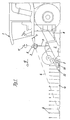
- FIG. 2 shows a plan view of a combine harvester 1 in use.
- the combine harvester 1 and the cutting unit 2 cut grain from the processing field 10 over a width determined therefrom.
- the existing stock edge 14 is shifted parallel to the direction of travel 12 by the actual working width of the cutting unit 2 into a new machining edge 20.
- This new processing edge 20 is decisive for the tracking of a subsequent combine harvester or the next time the combine harvester 1 travels along as a new existing edge 20.
- the task of the operator of a combine harvester 1 is to guide the cutting unit 2 with the highest possible utilization and without the crop material remaining along the existing edge 14. For this purpose, automatic steering systems on agricultural machines 1 have proven to be particularly effective.
- a downstream steering controller detects the generated locating signal and uses an electrohydraulic steering device known to the person skilled in the art to control the steering wheels 25 on a steering axle 24 of the combine harvester 1 in such a way that the control deviation detected by the locating device 3 is corrected , It has proven to be particularly advantageous to also measure the utilization of the cutting unit 2 as an actual utilization of the cutting unit 2 by means of a locating device 7 arranged in the feed area. As a result, the course of the crop edge 14 in relation to the direction of travel 12 of the combine harvester 1 can be scanned in advance at two spaced apart locations.
- absolute coordinates can be assigned to the existing edge 14 and transversely to the direction of travel 12 also to the new machining edge 20.
- the locating device 3 is mounted on the right-hand cutting unit wall above the existing edge 14, inclined towards the latter. In the illustrated standing edge 14, 20, a change in the course is shown, which must result in a transition from a straight drive into a cornering of the combine harvester 1.
- the locating device 3 was pivoted by the actuating device at an angle a with respect to the longitudinal axis 26 in the direction of travel 12 of the combine harvester 1 about the vertical axis 11 to the existing edge 14, this angle a being present as a control deviation on the steering controller, but the steering wheels 25 still not Show change of direction to track upcoming cornering.
- the steering controller can be designed such that a steering wheel movement is only permitted when the locating device 7 indicates compliance with load limits that could be exceeded due to the intended necessary steering movement.
- the detection area 13 of the locating device 3 was pivoted according to the invention with the middle detection area 19 onto the existing edge 14.
- the scanning beam 4 shown scans a point on the stubble and is located in the stubble 15 sensing area.
- This area lies between the right area boundary 18 and the middle area 19.
- the ears 16 sensing area lies between the middle area 19 and the left area boundary 17.
- the locating device 3 detects the stubble 15 sensing area from the ears 16 sensing area by different distances.
- the contour 27 scanned over the opening angle b has a greater distance in the detection area 13 of the locating device 3, in the stubble area 15, than in the ear area 16.
- the guide variable "standing edge 14" is determined by the locating device 3 based on the sudden change in the distance signal between the Areas 15, 16 recognized and tracked by the location system according to the invention.
- the absolute distance and the difference in the distances with respect to the two scanning areas 15, 16 have no influence on the determination of the position of the guide variable 14.
- FIG. 3 shows a top view of a forage harvester 30 with two locating systems according to the invention arranged thereon and two associated locating devices 28, 50 and a transport vehicle 36 traveling in parallel.
- the forage harvester 30 picks up crop lying on the processing field 10 in swath 34, processed it and then overloads it by means of an overloading elbow 32 onto a loading container 38, 39 pulled by the towing vehicle 37.
- the distance between the locating device 28 and the swath 34 is scanned in a contactless manner by the locating device 28 fixedly arranged on the longitudinal axis 35 of the forage harvester 30, on the driver's cab thereof, by means of a scanning beam which is oscillating in a detection area 13.
- the guide variable is recognized by determining the shortest distance between the swath 34 and the locating device 28, and the detection area 13 of the locating device 28 is pivoted by the actuating device mounted inside the housing of the locating device 28 such that the guide variable im middle detection area 19 of the locating device 28 is recognized.
- the size of the resulting angle a, between the longitudinal axis 35 of the forage harvester 30 and the area center 19 of the detection area 13, is fed to an automatic steering device known to the person skilled in the art and used by the latter to track the forage harvester 30.
- two locating devices 7 are arranged in the feed area on both sides transversely to the working direction.
- the positions of the swath 34 which are spaced apart from one another by the locating devices 7 and 28, with respect to the forage harvester 30, can be fed to an automatic steering device provided on the forage harvester 30 and enable the swath 34 to be tracked automatically and precisely Locating device 7 for localizing the position of the swath 34.
- a navigation antenna 42 is also arranged on the cabin roof of the forage harvester 30.
- the absolute position of the forage harvester 30 with respect to the processing field 10 can hereby be determined.
- the individual positions show the lane of the forage harvester 30 in the course and can be stored in a memory.
- the positions of the swath 34 detected by the locating device 28, 7, assigned to the navigated positions of the forage harvester 30, can be stored. From the known distance between the navigation antenna 42 and the locating device 30 on the forage harvester 30, the absolute orientation of the longitudinal axis 35 with respect to the processing field 10, the angle a and the distance between the contour 29 and the locating device 28, Predictively determine the absolute position of the swath 34.
- Advantageous tracking of the forage harvester 30 on the basis of the recorded absolute position of the swath 34, in conjunction with the current navigated position of the forage harvester 30 on the processing field 10, can hereby be carried out according to the invention.
- the position of the swath 34 in the pick-up area of the pickup 31 of the forage harvester 30 can also be calculated in relation to the navigated position of the forage harvester 30 and used directly for tracking or can be stored in a storage device for this purpose.
- a route planning system 40 is also installed on the forage harvester 30. This can generate a route for the forage harvester 30 and, according to the invention, can also control the route 41 for the transport vehicle 36.
- the towing vehicle 37 is equipped with a right-of-way control 46 and a steering control 47. These controls 46, 47 are connected to the route planning system 40 by means of a data transmission link 39.
- the forage harvester 30 and the towing vehicle 37 each have, for example, a radio transmission and reception device and associated radio antennas 43, 44.
- a steering angle and a driving speed for the towing vehicle 37 are determined from the determined absolute position of the swath 34 by the route planning system 40 and transmitted to the controls 46, 47 in such a way that crops can be safely overloaded onto the loading containers 38, 39 ,
- a navigation antenna 44 is located on the towing vehicle 37 to determine the absolute position on the processing field 10.
- the route 41 for the transport vehicle 36 can be specified by the route planning system 40 by transmitting an absolute route 41 with respect to the processing field 10.
- a tracking of the transport vehicle 36 along the swath 34 in connection with the position of the forage harvester 30 can also be carried out automatically by a device on the towing vehicle 37.
- the current position of the forage harvester 30 and the determined position of the swath 34 are then transmitted to the towing vehicle 37 for this purpose.
- the operator of the towing vehicle 37 can operate or at least monitor the automatic tracking of the transport vehicle 36 by means of an operating device 48.
- a further locating device 50 for detecting a relative position of the loading container 38, 39 with respect to the forage harvester 30 is attached to the forage harvester 30 shown in FIG.
- This locating device 50 is fastened in the rear area on the longitudinal axis 35 of the forage harvester 30 so as to be pivotable about a vertical axis 53.
- the detection area 13 of this locating device 50 can therefore be pivoted by approximately 360 ° to find and track a guide variable by an actuating device. In this way, guide variables to the left, to the right of or behind the forage harvester 30 can be sampled according to the invention.
- a locating device 50 designed as a laser reflex locating device is used here, the detection area 58 being shown aligned with a vertically standing rear loading container edge 54.
- the locating system aligns the locating device 50 by means of the actuating device on the forage harvester 30 in such a way that the recognized edge of the loading container 54, 55 is detected in the central detection area 19 of the detection area 58 of the locating device 3.
- the position of the guide variable 54 recognized by the location system is used according to the invention to control the setting of the supercharger manifold 32.
- the overloader 32 can be pivoted remotely by the operator of the forage harvester 30 about a vertical axis of rotation, so that different angles between the longitudinal axis 35 of the forage harvester 30 and the longitudinal axis 51 of the overloader 32 can be set. In this way, the crop can be overloaded on loading containers 38, 39 which are located to the right, left of or behind the forage harvester 30.
- the relative orientation of the locating device 50 on the forage harvester 30, in particular the angle d, is used according to the invention to adjust the orientation of the longitudinal axis 51 of the overloader 32 relative to the longitudinal axis 51 of the forage harvester 30 defined as zero position for automatic control of the overloader 32.
- At least one overload flap 57 is attached to the well-dispensing side of the overloader 32, which can be remotely pivoted about an approximately horizontal axis lying transversely to the longitudinal axis 51. With this, the relative discharge direction of the crop and, in connection therewith, also the loading width in the direction of the longitudinal axis 51 can be controlled.
- the distance between the forage harvester 30 and the loading container wall 49 can be determined, for example, from the relative position of the loading container edge 54, 55 to the forage harvester 30 recognized by the locating device 50, based on the distance signal present at the right-hand area boundary 18. This distance is used according to the invention to control the loading flap 57. If the transport vehicle 36 now moves relative to the forage harvester 30 on the processing field 10, the setting of the overloading elbow 32 is changed according to the movement in such a way that the crop is overloaded to approximately the same location in the loading container 38, 39. The respective setting of the supercharger bend 32 is detected by sensors and related to the signals of the locating device 50 in a device.
- This device can also be connected to the control elements for manual control of the supercharger manifold 32 and can also supply control signals for the setting of the location system.
- the detection area 58 of the locating device 50 is automatically aligned in an initialization step in connection with the transfer direction selected by the operator, parallel to the longitudinal axis 51 of the transfer manifold 32.
- the locating system uses the scanned contour 56 to search for a loading container edge 54, 55 by the adjusting device adjusting the angle d over a larger area until the required jump in distance in the contour 56 is recognized.
- the angle d occurring here and the determined distance are assigned to the current setting of the supercharger bend 32 as the basic orientation and an automatic control of the supercharger bend 32 dependent on this is started, the detection area 58 of the locating device 50 according to the invention by means of an actuating device of the loading container edge 54, 55 is tracked.
- the automatic control now automatically compensates for the relative movements between the forage harvester 30 and the transport vehicle 36, a manually generated override of the setting of the overloader 32, for example by the operator, interrupting the automatic control only during the manual adjustment, the new setting of the overloader 32 is automatically converted into a corrected new basic alignment and then continues to be executed.
- the location system can recognize from the individual distance values and in particular from the values at the area boundaries 17 and 18 whether the load container edge 54, 55 found is a rear load container edge 54 or a front load container edge 55.
- a rear loading container edge 54 is recognized by the shorter distance signal at the right area boundary 18 compared to the distance signal at the left area boundary 17.
- the loading container 38 shown is already partially filled with crop 52 in the front area, so that further filling can only be continued in the rear part of the loading container 38. It has proven to be particularly advantageous to sight a front loading container edge 55 when filling the front region of the loading container 38, 39 and to target the rear loading container edge 54 when filling in the rear part of the loading container 38, 39.
- a change can be manually controlled, activated by an operator or carried out automatically depending on the angle d. If, for example, the locating device 50 comes close to an actuating stop during the tracking of the front loading container edge 55 according to the invention, the control of the overloader 32 according to the invention is automatically interrupted, a rear loading container edge 54 is searched for, the new basic orientation of the locating device 50 between the loading container edge 54 and the The setting of the supercharger manifold 32 is assigned in a corrected manner and the automatic control is resumed.
- the scanning distance or also the width of the detection area 58 can be varied according to the invention, in order first to quickly find a loading container 38, 39 or a loading container edge 54 by scanning a larger area To get 55. After a loading container 38, 39 or a loading container edge 54, 55 has been found, the detection area can be restricted according to the position according to the invention and adjusted accordingly. This adaptation is advantageously done adaptively.
- the locating device 50 and / or the guide variable to be recorded can also be connected to a navigation antenna 42.
- the absolute position of the guide variable in particular the approximate position of the edge of a loading container 54, 55, can then be determined, and a faster search for the guide variable can be carried out by the locating system through a specific search area.
- FIG. 4 shows a side view of a locating device 3, 28, 50 which can be pivoted on a holding tube 9 about a vertical axis 62 and horizontal axis 61.
- the locating device 3, 28, 50 is shown arranged on a rotating ring 68 and a bearing 69 arranged coaxially to the vertical axis 62 within a protective housing 71.
- the turntable 68 has, on the circumference, at least in some areas, a set of teeth 70, in which a gear wheel 72 driven by a servomotor 60 engages.
- the servomotor 60 is articulated to the protective housing 71 and enables the locating device 3, 28, 50 to be given away remotely about the vertical axis 62 with respect to the protective housing 71 or the holding tube 9.
- the detection area can be covered by this swivel drive 60, 68, 69, 70, 72 13.58 of the locating device 3.28.50 are tracked according to the invention to a guide value 14.34.54.55.
- a sensor 63 is mounted in the protective housing 71, axially aligned with the vertical axis 62, which detects the pivoting of the locating device 3, 28, 50 with respect to the holding tube 9 by means of a lever 67.
- a further servomotor 65 is articulated on the holding tube 9, by means of which the entire protective housing 71 can be pivoted about the horizontal axis 61. This makes it possible to adjust the inclination of the scanning beam 4, for example toward an existing edge 14, or to adapt a setting of the scanning distance that is dependent on the driving speed.
- a changed inclination is indicated by the dash-dot line representation 64.
- the relative orientation of the locating device 3, 28, 50 is detected by a position sensor 66, which determines the travel of the servomotor 65.
- the control of the servomotors 60, 65 and the evaluation of the sensor signals of the sensors 63, 66 is carried out by devices, not shown, which are arranged within the locating device 3, 28, 50.
- the axes 61, 63 can also be arranged within the locating device 3, 28, 50 and the detection area 13, 58 of the locating device 3, 28, 50 can be tracked according to the invention by the guide devices 14, 14, 54, 54, 55 present there.
- the exemplary embodiments described show particularly advantageous applications of the location system according to the invention, the invention not being limited to these is.
- the use of the location system on other well-known agricultural used machines, such as a tractor, a work vehicle or a towing vehicle 37, for locating and / or automatically tracking a Guide variable, such as a stock edge 14.20, one of a track marker generated track, a swath 34, a plow furrow, a tramline or different processing edge, is at the discretion of the specialist and will covered by the invention.
- the location system can also be operated on a processing device, such as using a plow and adjusting the Processing device and / or for tracking the processing device and / or the use the corresponding towing vehicle 37.
Abstract
Description
Die DE 197 26 917 A1 beschreibt eine Vorrichtung an einer Landmaschine zur berührungslosen Abtastung von sich über den Boden erstreckenden Konturen. An der Landmaschine ist in Fahrtrichtung vorausschauend, eine Laserentfernungsmessvorrichtung angebracht, die mittels eines in einer zum Bearbeitungsfeld geneigten Abtast-Ebenen verschwenkten Abtast- Laserstrahls, eine Kontur des Bearbeitungsfeldes aus der Anbringungsposition und den jeweiligen Entfernungssignalen in Verbindung mit dem Schwenkwinkel des Abtaststrahl ermittelt. Die Verschwenkung eines Abtast- Laserstahls mittels einer um eine vertikale Schwenkachse pendelnd an der Landmaschine angebrachten Laserentfernungsmessvorrichtung oder mittels einer beweglichen Schwenkoptik in einer fest an der Landmaschine angeordneten Laserentfernungsmessvorrichtung wird offenbart. Die hohe Abtastentfernung der Laserentfernungsmessvorrichtung ermöglicht eine Abtastung der Kontur über eine große Breite vor der Landmaschine sowie eine frühe Erkennung von Änderungen im Verlauf einer aus der Kontur ermittelten, einer nachgeschalteten automatischen Spurführung zugeführten Leitgröße. Durch diese breite Abtastung der Kontur können ferner große Abweichungen der Leitgröße erkannt werden und wobei ferner auch bei einer trägen Reaktion der Landmaschine hierauf, die Leitgröße den Abtastbereich nicht verlassen kann. Durch die frühe Abtastung kann die Landmaschine vorausschauend auf die Leitgröße ausgerichtet werden, verliert aber hierdurch den direkten Bezug zur momentanen Lage der Leitgröße bezüglich des Einzugsbereichs der Arbeitsorgane der Landmaschine. Es kann daher zur ungenügenden Auslastung eines Scheidwerks oder zu Erntegutverlusten, durch ein Vorbeifahren des Einzugsbereichs an dem stehenden oder liegenden Erntegut, kommen. Der große Erfassungsbereich der Laserentfemungsmessvorrichtung erfordert nachteilig eine hohe Abtastgeschwindigkeit des Laserstrahls und führt ferner zur Speicherung einer größeren Datenmenge und längeren Auswertedauer der Daten.
In der DE 197 19 939 A1 wird eine Ortungseinrichtung an einer lenkbaren Erntemaschine vorgeschlagen, die in Fahrtrichtung vorausschauend eine Leitgröße, wie beispielsweise eine Getreidekante, zum einen weit voraus und zum anderen zusätzlich im Einzugsbereich der Arbeitsorgane der Landmaschine abtastet. Der nachgeschaltete Lenkregler erhält somit ein fernes und ein nahes Signal über die relative Lage der Leitgröße zur Erntemaschine und kann dann die Lenkbewegung so veranlassen, dass eine ausreichend zuverlässige Erntegutaufnahme bei gleichzeitiger frühzeitiger Ausrichtung der Erntemaschine entlang der Leitgröße erzielt wird. Auf eine größere Änderung der Leitgröße ist folgend eine größere Lenkbewegung notwendig, diese wird von der fernen Ortungsvorrichtung erkannt, aber von dem nahen Abtastsignal vorteilhaft beschränkt. Damit nun das ferne Abtastsignal hierbei die Leitgröße nicht verliert, ist eine möglichst breite Erfassung des Bereichs quer zur Leitgröße erforderlich. Dies verteuert nachteilig die Ortungsvorrichtung für diese Fernabtastung und bedingt eine höhere Abtastrate der Vorrichtung sowie eine längere Datenauswertung der anfallenden höheren Datenmenge.
Vorteilhaft verliert die Ortungsvorrichtung selbst bei größeren Änderungen im Verlauf der Leitgröße, die Leitgröße nie. Der Erfassungsbereich der Ortungsvorrichtung wird vorteilhaft hierdurch von der Bewegung der Arbeitsmaschine entkoppelt und bleibt auf die Leitgröße ausgerichtet. Weiterhin kann die Leitgröße vorteilhaft auf einen geringen Bereich eingeschränkt und es können ferner Ortungsvorrichtungen mit einem bauartbedingten schmalen Erfassungsbereich, wie beispielsweise die im Stand der Technik beschriebene Ultraschall- Ortungsvorrichtung, verwendet werden. Die Verwendung eines schmalen Erfassungsbereichs der Ortungsvorrichtungen erbringt in Verbindung mit der vorgeschlagenen Lösung, die weiteren nachfolgend beschriebenen Vorteile. Die Ortungsvorrichtungen sind hierdurch kostengünstiger. Dies wird insbesondere durch die Verwendungsmöglichkeit einfacher Schwenkeinrichtung für das berührungslos arbeitende Abtastsignal erreicht. Weiterhin lassen sich derartige Ortungsvorrichtungen vorteilhaft gezielt auf eine Leitgröße ausrichten und werden dann nicht durch weitere im Umfeld der Leitgröße vorhandene eventuell ähnliche Leitgrößen oder weitere vorhandene miterfasste Konturänderungen beeinflusst. Ferner ergibt sich die Möglichkeit eine höhere Abtastrate bei einer vergleichbar geringeren Datenmenge zu erzielen. Die Zuverlässigkeit der Erkennung der Leitgrößen wird hierdurch merklich erhöht.
Vorteilhaft lässt sich die Ortungsvorrichtung mit geringem Erfassungsbereich, beispielsweise zur Initialisierung des Ortungssystems, beispielsweise zur automatischen Anpassung an unterschiedliche Arbeitsbreiten der Vorsatz- oder Arbeitsgeräte oder zur Findung einer Leitgröße, zunächst automatisch oder manuell über einen Bereich, mittels der erfindungsgemäß vorhandenen Stelleinrichtung, verschwenken um dann die hierbei gefundene oder ausgewählte Lage einer Leitgröße gegenüber der Arbeitsmaschine, als Basisausrichtung oder Nulllage zu verwenden.
Durch die gegenüber der gesamten Arbeitsmaschine vernachlässigbaren Eigenmasse der Ortungsvorrichtung wird vorteilhaft, eine Verstellung der relativen Ausrichtung der Ortungsvorrichtung an der Arbeitsmaschine mit einer hohen Dynamik möglich. Eine direkte Nachführung der Ortungsvorrichtung, aufgrund einer Änderung der Lage der Leitgröße gegenüber der Arbeitsmaschine, kann hierdurch ohne nennenswerte Verzögerung und Regelabweichung vorteilhaft durchgeführt werden.
- Figur 1
- ein Mähdrescher mit am Schneidwerk angeordneter Ortungsvorrichtung in einer Seitenansicht,
- Figur 2
- eine Draufsicht auf einen im Arbeitseinsatz befindlichen Mähdrescher,
- Figur 3
- eine Draufsicht auf einen Feldhäcksler mit zwei daran angeordneten Ortungsvorrichtungen und ein parallelfahrendes Transportfahrzeug und
- Figur 4
- eine Seitenansicht eines an einem Halterohr um eine vertikal und horizontale Achse schwenkbare Ortungsvorrichtung.
Es kann ferner eine Laserreflexortungsvorrichtung verwendet werden, die einen Abtaststrahl 4 über eine großen Winkel, bis zu 360° verschwenkt. Wird dann eine Leitgröße wie zuvor beschrieben erkannt, wird der abgetastet Bereich auf wenige Grad (15°) eingeschränkt und die Ortungsvorrichtung 3 dann mittels der Stelleinrichtung auf die Leitgröße ausgerichtet.
Die Verwendung einer bekannten Ultraschallortungsvorrichtung ist weiterhin möglich. Dabei wird die Ortungsvorrichtung 3 auf dem Halterohr 9 mit ihrer Schallkeule von oben auf die Bestandskante ausgerichtet angebracht. In einem Initialisierungsschritt wird die der Basisausrichtung so ausgerichtet, dass das dabei sensierte Echosignal, etwa einem halben Echosignal entspricht, welches bei einer voll auf den Bestand ausgerichteten Schallkeule entsteht.
Unabhängig der verwendeten Ortungsvorrichtung 3 beziehungsweise des Start- oder Initialisierungsschritts, bewirkt während dem Arbeitsbetrieb des Mähdreschers 1, eine sich veränderte Lage der Leitgröße bezüglich des Mähdreschers 1 oder des Mähdreschers 1 bezüglich der Leitgröße, eine erfindungsgemäße Nachführung des Erfassungsbereichs der Ortungsvorrichtung 3 mittels der Stelleinrichtung, wobei der Abtaststrahl 4 oder die Schallkeule stets etwa zu gleichen Teilen die benachbarten Bereiche zur Leitgröße abtastet. Die sich einstellende veränderte Ausrichtung der Ortungsvorrichtung 3 bezüglich des Mähdreschers 1 wird von einer Sensorik erfasst und einer nachgeschalteten Einrichtung, wie beispielsweise der automatischen Spurführung als Ist-Signal zugeführt. Anhand der Bezugsausrichtung wird von der Einrichtung zur Spurführung eine Regelabweichung ermittelt und ein entsprechendes Stellsignal zur Verstellung der Lenkräder erzeugt. Hierdurch wird die Fahrtrichtung 12 des Mähdreschers 1 derart beeinflusst, dass der Mähdrescher 1 dem geänderten Verlauf der Bestandskante folgt. Verursacht durch die Änderung der Fahrtrichtung 12 des Mähdreschers 1 wird der Erfassungsbereich der Ortungsvorrichtung 3 relativ zur Bestandskante bewegt. Die Ausrichtung der Ortungsvorrichtung 3 wird erfindungsgemäß durch das Ortungssystem in Richtung der Bezugsausrichtung verstellt, wodurch gleichzeitig eine Reduzierung der Regelabweichung erfolgt. Die Regelabweichung wird dann zu Null, wenn die Ortungsvorrichtung 3 die Bestandkante wieder mit der zuvor bestimmten Bezugausrichtung zum Mähdrescher 1 erfasst.
Die Ortungsvorrichtung 3 kann ferner um eine horizontale Achse, an dem Halterohr 9 schwenkbar befestigt sein. Diese Möglichkeit dient einer einmaligen Justage der Ortungsvorrichtung 3 an dem Halterohr 9, bezüglich der Neigung an dem Schneidwerk 2 zum Bestand 6 hin. Ferner kann diese Einstellmöglichkeit auch von einer Stelleinrichtung automatisch, zur Einhaltung einer konstanten Entfernung, beispielsweise zum Bearbeitungsfeld 10, ferngesteuert durchgeführt werden. Besonders zur Anpassung der Ausrichtung der Ortungsvorrichtung 3 an verschiedene Bestandshöhen und/oder Schnitthöhen des Schneidwerks 2, kann diese horizontale Stellfunktion Verwendung finden. Weiterhin ist es besonders vorteilhaft die Vorausschau der Ortungsvorrichtung 3, zum Ausgleich von wellenförmigen Verläufen entlang der Bestandskante beziehungsweise zur Stabilisierung des Lenkregelkreises, an unterschiedliche Fahrgeschwindigkeiten, durch unterschiedliche Neigungen einzustellen. Eine höhere Fahrgeschwindigkeit bewirkt dann eine weitere Vorausschau der Ortungsvorrichtung 3.
An dem Schneidwerk 2 ist im Einzugsbereich eine weitere Ortungsvorrichtung 7 quer zur Fahrtrichtung 12 des Mähdreschers 1 ausgerichtet angeordnet. Diese Ortungsvorrichtung 7 ermittelt die Auslastung des Schneidwerks 2 anhand des Abstandes zwischen dem am Bestand 6 vorbeigeführten Haltearm 23 des Halmteilers 22 und dem Bestand 6. An der Ortungsvorrichtung 3 ist obenauf eine Navigationsantenne 5 angeordnet. Diese ermittelt die absolute Position der Ortungsvorrichtung 3 auf dem Bearbeitungsfeld 10. Die von den Ortungsvorrichtungen 3 und 7 ermittelten Lagen der Leitgröße zum Schneidwerk 2, lassen sich erfindungsgemäß der absoluten Position der Ortungsvorrichtung 3 zuordnen und gegebenenfalls in einer Speichereinrichtung hinterlegen. Der Verlauf der Leitgröße kann dann bezüglich des Bearbeitungsfeldes 10 aufgezeichnet, zur direkten Spurführung des Mähdreschers 1 verwendet und ferner als Basis einer nachfolgenden spurgeführten Entlangfahrt der selben oder einer anderen Arbeitsmaschine an einer Bestandskante dienen. Die Navigationsantenne 5 kann auch von der Ortungsvorrichtung 3 beabstandet an dem Mähderscher 1 angebracht werden und beispielsweise die Positionsdaten für eine Spurführung und/oder Ertragskartierung des Mähdreschers 1 liefern.
Die Ortungsvorrichtung 3 ist an der rechten Schneidwerkswand oberhalb der Bestandskante 14 zu dieser hin geneigt angebracht. In der dargestellten Bestandskante 14, 20 wird eine Änderung im Verlauf gezeigt, der einen Übergang von einer Geradeausfahrt in eine Kurvenfahrt des Mähdreschers 1 zur Folge haben muss. Erfindungsgemäß wurde die Ortungsvorrichtung 3 von der Stelleinrichtung mit einem Winkel a gegenüber der Längsachse 26 in Fahrtrichtung 12 des Mähdreschers 1 um die vertikale Achse 11 zur Bestandskante 14 hin verschwenkt, wobei an dem Lenkregler dieser Winkel a als Regelabweichung ansteht, jedoch die Lenkräder 25 noch keine Veränderung der Laufrichtung zur Verfolgung der bevorstehenden Kurvenfahrt anzeigen. Der Lenkregler kann dabei so ausgelegt sein, dass erst dann eine Lenkräderbewegung zugelassen wird, wenn die Ortungsvorrichtung 7 die Einhaltung von Auslastungsgrenzen, die aufgrund der beabsichtigten notwendigen Lenkbewegung überschritten werden könnten, anzeigt.
Der Erfassungsbereich 13 der Ortungsvorrichtung 3 wurde erfindungsgemäß, mit dem mittleren Erfassungsbereich 19 auf die Bestandkante 14 verschwenkt. Der gezeigte Abtaststrahl 4, tastet einen Punkt auf den Stoppeln ab und befindet sich dabei im Tastbereich Stoppeln 15. Dieser Bereich liegt zwischen der rechten Bereichsgrenze 18 und der Bereichsmitte 19. Der Tastbereich Ähren 16 liegt zwischen der Bereichsmitte 19 und der linken Bereichsgrenze 17. Beide Bereiche 15,16 zusammen ergeben in einer Ebene gesehen, den Erfassungsbereich 13 der Ortungsvorrichtung 3. Von der Ortungsvorrichtung 3 wird der Tastbereich Stoppeln 15 von dem Tastbereich Ähren 16 durch unterschiedliche Entfernungen erkannt. Die über den Öffnungswinkel b abgetastete Kontur 27, besitzt im Erfassungsbereich 13 der Ortungsvorrichtung 3, im Tastbereich Stoppeln 15, eine größere Entfernung als im Tastbereich Ähren 16. Die Leitgröße "Bestandskante 14" wird von der Ortungsvorrichtung 3 anhand der sprunghaften Änderung des Entfernungssignals zwischen den Bereichen 15,16 erkannt und von dem Ortungssystem erfindungsgemäß verfolgt. Die absolute Entfernung sowie der Unterschied in den Entfernungen bezüglich der beiden Tastbereiche 15,16 haben keinen Einfluss auf die Bestimmung der Lage der Leitgröße 14.
An der gezeigten Pickup 31 sind im Einzugsbereich beidseitig quer zur Arbeitsrichtung ausgerichtet, zwei Ortungsvorrichtungen 7 anbracht. Diese tasten in einer bestimmten Höhe mit je einem Abtaststrahl 33, jeweils zum in der Regel von der Pickup 31 mittig aufgenommenen Schwad 34, den Abstand zum Schwad 34 ab. Diese Abstände zeigen die Lage des Schwads 34 im Einzugsbereich der Pickup 31 an. Die von den Ortungseinrichtungen 7 und 28 ermittelten voneinander beabstandeten Lagen des Schwads 34, bezüglich des Feldhäckslers 30, können einer auf dem Feldhäcksler 30 vorhanden automatischen Lenkeinrichtung zugeführt werden und ermöglichen eine automatische genaue Verfolgung des Schwads 34. Dabei dient die Ortungsvorrichtung 28 zur vorausschauenden und die Ortungsvorrichtung 7 zur nahen Ortung der Lage des Schwades 34.
Auf dem Kabinendach des Feldhäckslers 30 ist weiterhin eine Navigationsantenne 42 angeordnet. Die absolute Position des Feldhäckslers 30 bezüglich des Bearbeitungsfeldes 10 kann hiermit ermittelt werden. Die einzelnen Positionen zeigen im Verlauf die Fahrspur des Feldhäckslers 30 an und können in einem Speicher angespeichert werden. Erfindungsgemäß können die von der Ortungseinrichtung 28,7 erfassten Lagen des Schwades 34, den navigierten Positionen des Feldhäckslers 30 zugeordnet abgespeichert werden. Aus der bekannten Entfernung, zwischen der Navigationsantenne 42 und der Ortungsvorrichtung 30 an dem Feldhäcksler 30, der absoluten Ausrichtung der Längsachse 35 bezogen auf das Bearbeitungsfeld 10, dem Winkel a und der Entfernung zwischen der Kontur 29 und der Ortungsvorrichtung 28, lässt sich erfindungsgemäß, die absolute Position des Schwades 34 vorausschauend ermitteln. Eine vorteilhafte Spurführung des Feldhäckslers 30 anhand der aufgezeichneten absoluten Lage des Schwades 34, in Verbindung mit der aktuellen navigierten Position des Feldhäckslers 30 auf dem Bearbeitungsfeld 10, lässt sich hiermit erfindungsgemäß durchführen. Auch die Lage des Schwades 34 im Einzugsbereich der Pickup 31 des Feldhäckslers 30 kann in bezug auf die navigierte Position des Feldhäckslers 30 berechnet und direkt zur Spurführung verwendet oder hierfür in eine Speichereinrichtung hinterlegt werden.
Auf dem Feldhäcksler 30 ist weiterhin ein Routenplanungssystem 40 installiert. Dieses kann eine Fahrtroute für den Feldhäcksler 30 erzeugen und erfindungsgemäß auch die Steuerung der Fahrtroute 41 für das Transportfahrzeug 36 übernehmen. Das Zugfahrzeug 37 ist hierzu mit einer Vorfahrtsteuerung 46 und einer Lenksteuerung 47 ausgestattet. Diese Steuerungen 46,47 sind mittels einer Datenübertragungsstrecke 39 mit dem Routenplanungssystem 40 verbunden. Hierzu besitzen der Feldhäcksler 30 und das Zugfahrzeug 37 jeweils beispielsweise eine Funksende- und -empfangseinrichtung sowie zugehörige Funkantennen 43,44. Erfindungsgemäß wird aus der ermittelten absoluten Lage des Schwades 34, von dem Routenplanungssystem 40, ein Lenkwinkel und eine Fahrgeschwindigkeit für das Zugfahrzeug 37 so ermittelt und an die Steuerungen 46,47 übertragen, dass eine sicher Überladung von Erntegut auf die Ladebehälter 38,39 erfolgen kann. Auf dem Zugfahrzeug 37 befindet sich zur Ermittlung der absoluten Position auf dem Bearbeitungsfeld 10 hierzu eine Navigationsantenne 44. Ferner kann die Fahrtroute 41 für das Transportfahrzeug 36, durch die Übertragung einer absoluten Fahrtroute 41 bezüglich des Bearbeitungsfeldes 10 von dem Routenplanungssystem 40 vorgegeben werden. Eine Spurführung des Transportfahrzeuges 36, entlang des Schwades 34 in Verbindung mit der Position des Feldhäckslers 30, kann auch von einer Einrichtung auf dem Zugfahrzeug 37 selbsttätig durchgeführt werden. Die aktuelle Position des Feldhäckslers 30 und die ermittelte Lage des Schwades 34, wird dann hierfür an das Zugfahrzeug 37 übermittelt. Der Bediener des Zugfahrzeugs 37 kann mittels einer Bedieneinrichtung 48 die automatische Spurführung des Transportfahrzeuges 36 bedienen beziehungsweise zumindest überwachen.
An dem in der Figur 3 dargestellten Feldhäcksler 30 ist eine weitere Ortungsvorrichtung 50, zur Erfassung einer relativen Lage des Ladebehälters 38,39 bezüglich des Feldhäckslers 30 befestigt. Diese Ortungsvorrichtung 50 ist im Heckbereich auf der Längsachse 35 des Feldhäckslers 30 um eine vertikale Achse 53 schwenkbar befestigt. Der Erfassungsbereich 13 dieser Ortungsvorrichtung 50 kann daher um annähernd 360° zur Findung und Verfolgung einer Leitgröße von einer Stelleinrichtung verschwenkt werden. Hierdurch lassen sich Leitgrößen links, rechts neben oder hinter dem Feldhäcksler 30 erfindungsgemäß abtasten. Eine als Laserreflexortungsvorrichtung ausgebildete Ortungsvorrichtung 50 wird hier verwendet, wobei der Erfassungsbereich 58 auf eine senkrecht stehende hintere Ladebehälterkante 54 ausgerichtet dargestellt wird. Von einem in einer Ebene oszillierend verschwenkten Laserstrahl, werden bei unterschiedlichen Schwenkwinkeln bezüglich der Ortungsvorrichtung 50, Abstandswerte aus der Laufzeit eines gesendeten und empfangenen Laserimpulses zwischen der Ortungsvorrichtung 50 und der abgetasteten Kontur 56 in Verbindung mit dem Schwenkwinkel ermittelt. Befindet sich im Erfassungsbereich 58 eine Ladebehälterkante 54,55 so wird diese anhand eines Entfernungssprungs in der abgetasteten Kontur 56, von der Ortungsvorrichtung 50 erkannt und als Leitgröße definiert. Erfindungsgemäß richtet das Ortungssystem die Ortungsvorrichtung 50 so mittels der Stellvorrichtung an dem Feldhäcksler 30 aus, dass die erkannte Ladebehälterkante 54,55 im mittleren Erfassungsbereich 19 des Erfassungsbereichs 58 der Ortungsvorrichtung 3 erfasst wird. Die von dem Ortungssystem erkannte Lage der Leitgröße 54 wird erfindungsgemäß zur Steuerung der Einstellung des Überladekrümmers 32 verwendet. Der Überladekrümmer 32 kann von dem Bediener des Feldhäckslers 30 ferngesteuert um eine vertikale Drehachse geschwenkt werden, so dass unterschiedliche Winkel zwischen der Längsachse 35 des Feldhäckslers 30 und der Längsachse 51 des Überladekrümmers 32 eingestellt werden können. Somit kann eine Überladung von Erntegut auf Ladebehältern 38,39 erfolgen, die sich rechts, links neben oder hinter dem Feldhäcksler 30 befinden. Die relative Ausrichtung der Ortungsvorrichtung 50 an dem Feldhäcksler 30, insbesondere der Winkel d, wird erfindungsgemäß zur Einstellung der Ausrichtung der Längsachse 51 des Überladekrümmers 32 gegenüber der als Nulllage definierten Längsachse 51 des Feldhäckslers 30 für eine automatische Steuerung des Überladekrümmers 32 verwendet.
An der gutabgebenden Seite des Überladekrümmers 32, ist wenigstens eine Überladeklappe 57 angebracht, die um eine annähernd horizontale und quer zur Längsachse 51 liegende Achse ferngesteuert verschwenkt werden kann. Hiermit kann die relative Abgaberichtung des Emtegutes und in Verbindung damit auch die Überladeweite in Richtung der Längsachse 51 gesteuert werden. Aus der von der Ortungsvorrichtung 50 erkannten relativen Lage der Ladebehälterkante 54,55 zum Feldhäcksler 30 hin, kann beispielsweise anhand des an der rechten Bereichsgrenze 18 vorhandenen Entfernungssignals, der Abstand zwischen dem Feldhäcksler 30 und der Ladebehälterwand 49 ermittelt werden. Dieser Abstand wird erfindungsgemäß zur Steuerung der Überladeklappe 57 verwendet. Bewegt sich nun das Transportfahrzeug 36 relativ zum Feldhäcksler 30 auf dem Bearbeitungsfeld 10, wird erfindungsgemäß die Einstellung des Überladekrümmers 32 entsprechend der Bewegung so verändert, dass das Erntegut in etwa auf die gleiche Stelle im Ladebehälter 38,39 überladen wird.
Die jeweilige Einstellung des Überladekrümmers 32 wird von Sensoren erfasst und in einer Einrichtung mit den Signalen der Ortungsvorrichtung 50 in Beziehung gesetzt. Diese Einrichtung kann weiterhin mit den Bedienelementen für eine manuelle Steuerung des Überladekrümmers 32 in Verbindung stehen und ferner auch Stellsignale für die Einstellung des Ortungssystems liefern. So wird beispielsweise der Erfassungsbereich 58 der Ortungsvorrichtung 50 zu Beginn einer automatischen Steuerung in einem Initialisierungsschritt automatisch in Verbindung mit der von dem Bediener gewählten Überladerichtung parallel zur Längsachse 51 des Überladekrümmers 32 ausgerichtet. Nachfolgend sucht das Ortungssystem anhand der abgetasteten Kontur 56 eine Ladebehälterkante 54,55, indem die Stelleinrichtung den Winkel d über einen größeren Bereich so lange verstellt, bis der erforderliche Entfernungssprung in der Kontur 56 erkannt wird. Anschließend wird der hierbei auftretende Winkel d und der ermittelte Abstand, der aktuellen Einstellung des Überladekrümmers 32 als Basisausrichtung zugeordnet und eine erfindungsgemäße, hiervon abhängige automatische Steuerung des Überladekrümmers 32 gestartet, wobei der Erfassungsbereich 58 der Ortungsvorrichtung 50 erfindungsgemäß mittels einer Stelleinrichtung der Ladebehälterkante 54,55 nachgeführt wird. Die automatische Steuerung gleicht nun die relativen Bewegungen zwischen dem Feldhäcksler 30 und dem Transportfahrzeug 36 automatisch aus, wobei eine manuell erzeugte Übersteuerung der Einstellung des Überladekrümmers 32, beispielsweise durch den Bediener, die automatische Steuerung nur während der manuellen Verstellung unterbricht, die neue Einstellung des Überladekrümmers 32 automatisch in eine korrigierte neue Basisausrichtung überführt und dann weiter ausgeführt wird.
Das Ortungssystem kann aus den einzelnen Entfernungswerten und insbesondere aus den Werten an den Bereichsgrenzen 17 und 18 erkennen, ob es sich bei der gefunden Ladebehälterkante 54,55 um eine hintere Ladebehälterkante 54 oder eine vordere Ladebehälterkante 55 handelt. In der gezeigten Ausrichtung des Erfassungsbereiches 58 wird durch das kürzere Entfernungssignal an der rechten Bereichsgrenze 18 gegenüber dem Entfernungssignal an der linken Bereichsgrenze 17 eine hintere Ladebehälterkante 54 erkannt. Der gezeigte Ladebehälter 38 ist schon zum Teil im vorderen bereich mit Erntegut 52 befüllt, so dass die weitere Befüllung nur im hinteren Teil des Ladebehälters 38 fortgeführt werden kann. Es hat sich als besonders vorteilhaft herausgestellt, bei der Befüllung des vorderen Bereiches des Ladebehälters 38,39 eine vordere Ladebehälterkante 55 und bei einer Befüllung im hinteren Teil des Ladebehälters 38,39, die hintere Ladebehälterkante 54 anzuvisieren. Ein Wechsel kann von einem Bediener manuell gesteuert, aktiviert oder auch in Abhängigkeit des Winkels d automatisch vorgenommen werden. Gelangt beispielsweise die Ortungsvorrichtung 50 bei der erfindungsgemäßen Verfolgung der vorderen Ladebehälterkante 55 in die Nähe eines Stell-Anschlags, wird automatisch die erfindungsgemäße Steuerung des Überladekrümmers 32 unterbrochen, nach einer hinteren Ladebehälterkante 54 gesucht, die neue Basisausrichtung der Ortungsvorrichtung 50 zwischen der Ladebehälterkante 54 und der Einstellung des Überladekrümmers 32 korrigiert zugeordnet und die automatische Steuerung wieder aufgenommen.
Während der Suche eines Ladebehälters 38,39 oder einer Ladebehälterkante 54,55 kann die Abtastentfernung beziehungsweise auch die Breite des Erfassungsbereich 58 erfindungsgemäß variiert werden, um zunächst durch die Abtastung eines größeren Bereiches, zu einer raschen Findung eines Ladebehälters 38,39 oder einer Ladebehälterkante 54,55 zu gelangen. Nachdem ein Ladebehälter 38,39 beziehungsweise eine Ladebehälterkante 54,55 gefunden wurde, kann der Erfassungsbereich entsprechend der Lage erfindungsgemäß eingeschränkt und entsprechend nachgeführt werden. Diese Anpassung erfolgt vorteilhaft adaptiv.
Die Ortungsvorrichtung 50 und/oder die zu erfassende Leitgröße kann ferner mit einer Navigationsantenne 42 in Verbindung gebracht werden. Anhand der aktuellen Position 45 des Transportfahrzeuges 36 kann dann die absolute Lage der Leitgröße insbesondere die ungefähre Lage einer Ladebehälterkante 54,55 bestimmt werden und so durch einen bestimmten Suchbereich eine schnellere Findung der Leitgröße von dem Ortungssystem herbeigeführt werden.
Die Steuerung der Stellmotoren 60,65 und die Auswertung der Sensorsignale der Sensoren 63,66 wird von nicht näher dargestellten, innerhalb der Ortungsvorrichtung 3,28,50 angeordneten Einrichtungen vorgenommen. Ferner können auch die Achsen 61,63 innerhalb der Ortungsvorrichtung 3,28,50 angeordnet und der Erfassungsbereich 13,58 der Ortungsvorrichtung 3,28,50 durch dort vorhandene Stelleinrichtungen, der Leitgröße 14,34,54,55 erfindungsgemäß nachgeführt werden.
- 1.
- Mähdrescher
- 2.
- Schneidwerk
- 3.
- Ortungsvorrichtung
- 4.
- Abtaststrahl
- 5.
- Navigationsantenne
- 6.
- Bestand
- 7.
- Ortungsvorrichtung
- 8.
- Hubzylinder
- 9.
- Halterohr
- 10.
- Bearbeitungsfeld
- 11.
- vertikale Achse
- 12.
- Fahrtrichtung
- 13.
- Erfassungsbereich
- 14.
- Bestandskante
- 15.
- Tastbereich Stoppeln
- 16.
- Tastbereich Ähren
- 17.
- linke Bereichsgrenze
- 18.
- rechte Bereichsgrenze
- 19.
- mittlerer Erfassungsbereich
- 20.
- Bearbeitungskante
- 22.
- Halmteiler
- 23.
- Haltearm
- 24.
- Lenkachse
- 25.
- Lenkräder
- 26.
- Längsachse
- 27.
- abgetastete Kontur
- 28.
- Ortungsvorrichtung
- 29.
- Schwadkontur
- 30.
- Feldhäcksler
- 31.
- Pickup
- 32.
- Überladekrümmer
- 33.
- Abtastsignal
- 34.
- Schwad
- 35.
- Längsachse
- 36.
- Transportfahrzeug
- 37.
- Zugfahrzeug
- 38.
- Ladebehälter
- 39.
- Ladebehälter
- 40.
- Routenplanungssystem
- 41.
- Fahrtroute
- 42.
- Navigationsantenne
- 43.
- Antenne
- 44.
- Antenne
- 45.
- Navigationsantenne
- 46.
- Vorfahrtsteuerung
- 47.
- Lenksteuerung
- 48.
- Bedieneinrichtung
- 49.
- Ladebehälterwand
- 50.
- Ortungsvorrichtung
- 51.
- Längsachse Überladekrümmer
- 52.
- überladenes Erntegut
- 53.
- vertikale Achse
- 54.
- hintere Ladebehälterkante
- 55.
- vordere Ladebehälterkante
- 56.
- abgetastete Kontur
- 57.
- Überladeklappe
- 58.
- Erfassungsbereich
- 60.
- Stellmotor
- 61.
- horizontale Achse
- 62.
- vertikale Achse
- 63.
- Sensor
- 64.
- geneigte Stellung
- 65.
- Stellmotor
- 66.
- Lagesensor
- 67.
- Hebel
- 68.
- Drehkranz
- 69.
- Lagerung
- 70.
- Verzahnung
- 71.
- Schutzgehäuse
- 72.
- Zahnrad
Claims (16)
- Ortungssystem an einer selbstfahrenden landwirtschaftlichen Arbeitsmaschine, wie beispielsweise Mähdrescher (1), Feldhäcksler (30) oder Zugfahrzeug (37), mit wenigstens einer berührungslos arbeitenden Ortungsvorrichtung (3,7,28,50) und mit wenigstens einer Stelleinrichtung (60,65), zur Verstellung der Ausrichtung der Ortungsvorrichtung (3,28,50) gegenüber der Arbeitsmaschine (1,30,37),
dadurch gekennzeichnet, dass
die Ortungsvorrichtung (3,28,50) einen die Leitgröße (14,34,54,55) beinhaltenden Erfassungsbereich (13,58) sensiert und die Lage des Erfassungsbereichs (13,58) gegenüber der Arbeitsmaschine (1,30,37) änderbar ist und die Änderungen in Abhängigkeit von der Änderung der Leitgröße (14,34,54,55) erfolgt. - Ortungssystem nach Anspruch 1,
dadurch gekennzeichnet, dass
der Erfassungsbereich (13,58) von einem in einer Ebene zwischen zwei Bereichsgrenzen (17,18) verschwenkbaren Abtaststrahl (4) oder von einem flächig abtastenden Strahlenbündel gebildet wird. - Ortungssystem nach wenigstens einem der Ansprüche 1 oder 2,
dadurch gekennzeichnet, dass
der Erfassungsbereich (13,58) der Ortungsvorrichtung (3,28,50) nur dann von zumindest einer Stelleinrichtung (60,65) gegenüber der Arbeitsmaschine (1,30,37) erneut ausgerichtet wird, wenn sich die erfasste Leitgröße (14,34,54,55) an die Bereichsgrenze (17,18) des Erfassungsbereichs (13,58) der Ortungsvorrichtung (3,28,50) bewegt. - Ortungssystem nach wenigstens einem der Ansprüche 1 bis 3,
dadurch gekennzeichnet, dass
der mittlere Erfassungsbereich (19) der Ortungsvorrichtung (3,28,50), mittels zumindest einer Stelleinrichtung (60,65), auf die Leitgröße (14,34,54,55) automatisch ausgerichtet wird. - Ortungssystem nach wenigstens einem der Ansprüche 1 bis 4,
dadurch gekennzeichnet, dass
die Ortungsvorrichtung (3,28,50) an der Arbeitsmaschine (1,30,37) mittels der zumindest einen Stelleinrichtung (60) um wenigstens eine annähernd vertikale Achse (11,53,62) gegenüber der Arbeitsmaschine (1,30,37) schwenkbar angeordnet ist. - Ortungssystem nach wenigstens einem der Ansprüche 1 bis 5,
dadurch gekennzeichnet, dass
die Leitgröße beispielsweise eine Bestandskante (14) und/oder ein Schwad (34) und/oder eine Furche und/oder eine Ladebehälterkante (54,55) ist. - Ortungssystem nach wenigstens einem der Ansprüche 1 bis 6,
dadurch gekennzeichnet, dass
die von der Ortungsvorrichtung (3,7,28,50) erfasste Lage der Leitgröße (14,34,54,55) gegenüber der Ortungsvorrichtung (3,7,28,50) und/oder die Ausrichtung der Ortungsvorrichtung (3,7,28,50) gegenüber der Arbeitsmaschine (1,30,37) bei der Einstellung wenigstens eines Parameters der Arbeitsmaschine (1,30,37) berücksichtigt wird. - Ortungssystem nach wenigstens einem der Ansprüche 1 bis 7,
dadurch gekennzeichnet, dass
die Ausrichtung der Ortungsvorrichtung (3,28,50), insbesondere der vertikale Winkel (a,d) gegenüber der Arbeitsmaschine (1,30,37) zur automatischen Spurführung der Arbeitsmaschine (1,30,37) verwendet wird. - Ortungssystem nach wenigstens einem der Ansprüche 1 bis 8,
dadurch gekennzeichnet, dass
zusätzlich die von der Ortungsvorrichtung (3,28,50) erfasste Lage der Leitgröße (14,34,54,55) gegenüber der Ortungsvorrichtung (3,28,50) zur automatischen Spurführung der Arbeitsmaschine (1,30,37) verwendet wird. - Ortungssystem nach wenigstens einem der Ansprüche 1 bis 9,
dadurch gekennzeichnet, dass
die Ausrichtung der Arbeitsmaschine (1,30,37) bezüglich der Leitgröße (14,34,54,55) im Einzugsbereich der Arbeitsmaschine (1,30,37) von wenigstens einer weiteren Ortungsvorrichtung (7) erfasst und zusätzlich bei der automatischen Spurführung mit berücksichtigt wird. - Ortungssystem nach wenigstens einem der Ansprüche 1 bis 10,
dadurch gekennzeichnet dass,
die Ausrichtung der Ortungsvorrichtung (3,28,50), insbesondere der Winkel (a,d) gegenüber der Arbeitsmaschine (1,30,37), bei einer automatischen Steuerung, wenigstens einer Einstellgröße eines Überladekrümmers (32) an einer Arbeitsmaschine (30), wie beispielsweise die Überladerichtung (51), berücksichtigt wird. - Ortungssystem nach wenigstens einem der Ansprüche 1 bis 11,
dadurch gekennzeichnet, dass
die Ausrichtung der Ortungsvorrichtung (3,28,50), insbesondere der vertikale Stellwinkel (a,d), gegenüber der Arbeitsmaschine (1,30,37), zur automatischen Koordination eines Arbeitsfahrzeugs (36) verwendet wird. - Ortungssystem nach wenigstens einem der Ansprüche 1 bis 12,
dadurch gekennzeichnet, dass
die Ortungsvorrichtung (3,7,28,50) mit einer Navigationsantenne (5) ausgestattet ist. - Ortungssystem nach wenigstens einem der Ansprüche 1 bis 13,
dadurch gekennzeichnet, dass
die von der Ortungsvorrichtung (3,7,28,50) erfasste Lage der Leitgröße (14,34,54,55) gegenüber der Ortungsvorrichtung (3,7,28,50) und die Ausrichtung der Ortungsvorrichtung (3,7,28,50) gegenüber der Arbeitsmaschine (1,30,37), in Verbindung mit der von der Navigationsantenne (5) ermittelten Position der Ortungsvorrichtung (3,7,28,50), in wenigstens einer Einrichtung zur Planung (40) und/oder Steuerung (46,47) entlang einer Fahrtroute (41) für die Arbeitsmaschine (1,30,37) und/oder eines Arbeitsfahrzeugs (36) verwendet wird. - Ortungssystem nach wenigstens einem der Ansprüche 1 bis 14,
dadurch gekennzeichnet, dass
die Bezugsausrichtung des Erfassungsbereichs (13,58) der Ortungsvorrichtung (3,28,50) von wenigstens einer Einstellung der Arbeitsmaschine (1,30,37) abhängig vorgegeben wird. - Ortungssystem nach wenigstens einem der Ansprüche 1 bis 15,
dadurch gekennzeichnet, dass
der Erfassungsbereich (13,58) der Ortungsvorrichtung (3,28,50) in Verbindung mit der zu ortenden Leitgröße (14,34,54,55) an diese angepasst werden kann.
Applications Claiming Priority (2)
| Application Number | Priority Date | Filing Date | Title |
|---|---|---|---|
| DE10204702 | 2002-02-05 | ||
| DE10204702A DE10204702A1 (de) | 2002-02-05 | 2002-02-05 | Ortungssystem an selbstfahrenden landwirtschaftlichen Arbeitsmaschinen |
Publications (3)
| Publication Number | Publication Date |
|---|---|
| EP1332659A2 true EP1332659A2 (de) | 2003-08-06 |
| EP1332659A3 EP1332659A3 (de) | 2004-08-25 |
| EP1332659B1 EP1332659B1 (de) | 2011-04-06 |
Family
ID=7713714
Family Applications (1)
| Application Number | Title | Priority Date | Filing Date |
|---|---|---|---|
| EP03001062A Revoked EP1332659B1 (de) | 2002-02-05 | 2003-01-18 | Ortungssystem an selbstfahrenden landwirtschaftlichen Arbeitsmaschinen |
Country Status (4)
| Country | Link |
|---|---|
| US (1) | US7155888B2 (de) |
| EP (1) | EP1332659B1 (de) |
| AT (1) | ATE504195T1 (de) |
| DE (2) | DE10204702A1 (de) |
Cited By (11)
| Publication number | Priority date | Publication date | Assignee | Title |
|---|---|---|---|---|
| EP1520461A1 (de) * | 2003-10-02 | 2005-04-06 | CLAAS Selbstfahrende Erntemaschinen GmbH | Transformationsvorrichtung innerhalb einer landwirtschaftlichen Maschine |
| EP1790207A1 (de) * | 2005-11-25 | 2007-05-30 | CLAAS Selbstfahrende Erntemaschinen GmbH | Verteileinrichtung für Gutstrom |
| EP1862049A1 (de) * | 2006-06-01 | 2007-12-05 | Alois Pöttinger Maschinenfabrik GmbH | Landmaschine |
| EP1977640A1 (de) * | 2007-04-04 | 2008-10-08 | CLAAS Selbstfahrende Erntemaschinen GmbH | Selbstfahrende landwirtschaftliche Erntemaschine mit steuerbarer Überladeeinrichtung |
| WO2009115404A1 (de) * | 2008-03-20 | 2009-09-24 | Deere & Company | Verfahren und vorrichtung zur lenkung einer zweiten landwirtschaftlichen maschine, die parallel fahrend zu einer ersten landwirtschaftlichen maschine über ein feld lenkbar ist |
| WO2011101458A1 (en) * | 2010-02-21 | 2011-08-25 | Cnh Belgium N.V. | Method for directing an unloading apparatus of a harvesting machine to a container |
| DE102011100054A1 (de) * | 2011-04-29 | 2012-10-31 | Alois Pöttinger Maschinenfabrik Gmbh | Landwirtschaftliche Maschine |
| CN106034436A (zh) * | 2016-05-23 | 2016-10-26 | 葛洲坝中固科技股份有限公司 | 一种恢复热脱附后土壤耕作性的方法 |
| EP3165062A1 (de) * | 2015-11-03 | 2017-05-10 | CLAAS Selbstfahrende Erntemaschinen GmbH | Umfelddetektionseinrichtung für landwirtschaftliche arbeitsmaschine |
| EP3289852A1 (de) * | 2016-08-29 | 2018-03-07 | CLAAS Selbstfahrende Erntemaschinen GmbH | Transportfahrzeug |
| EP4342279A1 (de) * | 2022-09-26 | 2024-03-27 | Agco Corporation | System und verfahren bezüglich eines landwirtschaftlichen geräts mit abbildungssystem |
Families Citing this family (27)
| Publication number | Priority date | Publication date | Assignee | Title |
|---|---|---|---|---|
| US7916898B2 (en) * | 2003-09-15 | 2011-03-29 | Deere & Company | Method and system for identifying an edge of a crop |
| DE102004010772A1 (de) | 2004-03-05 | 2005-10-06 | Deere & Company, Moline | Austrageinrichtung mit einer Messeinrichtung |
| DE102004052298A1 (de) * | 2004-10-06 | 2006-06-08 | Claas Selbstfahrende Erntemaschinen Gmbh | Überladeassistenzsystem |
| US7404355B2 (en) * | 2006-01-31 | 2008-07-29 | Deere & Company | Tractor and baler combination with automatic baling and tractor halt control |
| EP2020168A1 (de) * | 2007-08-03 | 2009-02-04 | AGROCOM GmbH & Co. Agrarsystem KG | Steuerungssystem für landwirtschaftliche Arbeitsmaschinen |
| ATE546991T1 (de) * | 2007-08-03 | 2012-03-15 | Agrocom Gmbh & Co Agrarsystem Kg | Landwirtschaftliche arbeitsmaschine |
| DE102009024062A1 (de) * | 2009-06-05 | 2010-12-09 | Valeo Schalter Und Sensoren Gmbh | Vorrichtung und Verfahren zur Anzeige von Objekten in einer Fahrzeugumgebung |
| US8602135B2 (en) * | 2009-06-25 | 2013-12-10 | Deere & Company | Drive quad module |
| US8738238B2 (en) | 2009-11-12 | 2014-05-27 | Deere & Company | Coordination of vehicle movement in a field |
| DE102009047585A1 (de) * | 2009-12-07 | 2011-06-09 | Deere & Company, Moline | Kombination aus einem Zugfahrzeug und einem Gerät |
| DE102010038661B4 (de) | 2010-07-29 | 2020-07-02 | Deere & Company | Erntemaschine mit einem an einem Fluggerät befestigten Sensor |
| US9002591B2 (en) * | 2011-02-18 | 2015-04-07 | Cnh Industrial America Llc | Harvester spout control system and method |
| US8606454B2 (en) | 2011-02-18 | 2013-12-10 | Cnh America Llc | System and method for synchronized control of a harvester and transport vehicle |
| DE102011002071A1 (de) * | 2011-04-15 | 2012-10-18 | Claas Selbstfahrende Erntemaschinen Gmbh | System und Verfahren zur Steuerung der Erntegutüberladung |
| US9169973B2 (en) * | 2012-12-18 | 2015-10-27 | Agco Corporation | Zonal operator presence detection |
| US9188986B2 (en) * | 2013-10-01 | 2015-11-17 | Jaybridge Robotics, Inc. | Computer-implemented method and system for dynamically positioning a vehicle relative to another vehicle in motion for on-the-fly offloading operations |
| EP3057398B1 (de) * | 2013-10-14 | 2020-07-08 | Kinze Manufacturing, Inc. | Autonome systeme, verfahren und vorrichtung für landwirtschaftliche tätigkeiten |
| BR102015013228B1 (pt) | 2014-06-13 | 2020-11-24 | Cnh Industrial America Llc | SISTEMA E METODO DE CONTROLE PARA UM VEfCULO AGRiCOLA |
| EP3162179A4 (de) * | 2014-06-30 | 2018-03-21 | Yanmar Co., Ltd. | Paralleles reisearbeitssystem |
| US9585309B2 (en) * | 2015-07-14 | 2017-03-07 | Cnh Industrial America Llc | Header height control system for an agricultural harvester |
| US9706697B2 (en) * | 2015-07-29 | 2017-07-18 | Claas Omaha, Inc. | Agricultural system with a baler and tow tractor and a steering arrangement by which the baler is steered autonomously |
| BE1024928B1 (nl) * | 2017-05-09 | 2018-08-13 | Cnh Industrial Belgium Nv | Verbeteringen in of met betrekking tot tractor/balenpers- combinaties |
| DE102018221250A1 (de) * | 2018-12-07 | 2020-06-10 | Robert Bosch Gmbh | Verfahren und System zur Steuerung einer landwirtschaftlichen Maschine |
| CN109392462B (zh) * | 2018-12-18 | 2023-11-17 | 北方民族大学 | 采摘黄花菜的机器人及方法 |
| DE102019211579A1 (de) * | 2019-08-01 | 2021-02-04 | Robert Bosch Gmbh | Verfahren und Vorrichtung zum Berechnen einer zu befahrenden Trajektorie für ein landwirtschaftliches Fahrzeug, Computerprogramm und maschinenlesbares Speichermedium |
| US20210185916A1 (en) * | 2019-12-23 | 2021-06-24 | Cnh Industrial America Llc | Sensor assembly for an agricultural header |
| US11533847B2 (en) * | 2019-12-23 | 2022-12-27 | Cnh Industrial America Llc | Control of a header of a harvester during a non-harvesting mode |
Citations (3)
| Publication number | Priority date | Publication date | Assignee | Title |
|---|---|---|---|---|
| DE19508942A1 (de) | 1995-03-13 | 1996-09-19 | Claas Ohg | Reflex-Ortungsvorrichtung |
| DE19719939A1 (de) | 1997-05-13 | 1998-11-19 | Claas Ohg | Automatisch lenkbare Erntemaschine |
| DE19726917A1 (de) | 1997-06-25 | 1999-01-07 | Claas Selbstfahr Erntemasch | Vorrichtung an Landmaschinen zur berührungslosen Abtastung von sich über den Boden erstreckenden Konturen |
Family Cites Families (11)
| Publication number | Priority date | Publication date | Assignee | Title |
|---|---|---|---|---|
| FR2240678B1 (de) * | 1973-08-14 | 1978-01-13 | Fahr Ag Maschf | |
| DD155157A1 (de) * | 1980-12-09 | 1982-05-19 | Bernd Kaempfe | Positioniereinrichtung,insbesondere zwischen erntemaschinen und transportfahrzeugen |
| JPS6434202A (en) * | 1987-07-30 | 1989-02-03 | Kubota Ltd | Working wagon of automatic conduct type |
| DE19508944A1 (de) * | 1995-03-13 | 1996-09-19 | Claas Ohg | Selbstlenkvorrichtung |
| EP0801885B1 (de) * | 1996-04-19 | 2002-01-09 | Carnegie-Mellon University | Erntegutlinie-Ortungsvorrichtung mit Bildverarbeitung |
| DE19743884C2 (de) * | 1997-10-04 | 2003-10-09 | Claas Selbstfahr Erntemasch | Vorrichtung und Verfahren zur berührungslosen Erkennung von Bearbeitungsgrenzen oder entsprechenden Leitgrößen |
| DE19845666B4 (de) * | 1998-10-05 | 2005-08-25 | Claas Selbstfahrende Erntemaschinen Gmbh | Lenkautomatik mit Ultraschall-Ortungsvorrichtung |
| DE19853085B4 (de) * | 1998-11-18 | 2014-03-20 | Claas Selbstfahrende Erntemaschinen Gmbh | Verfahren zum Justieren einer an einer Feldmaschine befestigten Sensoreinheit sowie eine Justiereinrichtung und eine Feldmaschine |
| US6216071B1 (en) * | 1998-12-16 | 2001-04-10 | Caterpillar Inc. | Apparatus and method for monitoring and coordinating the harvesting and transporting operations of an agricultural crop by multiple agricultural machines on a field |
| DE10064862A1 (de) * | 2000-12-23 | 2002-07-11 | Claas Selbstfahr Erntemasch | Vorrichtung und Verfahren zur Koordination und Einstellung von landwirtschaftlichen Fahrzeugen |
| US6615570B2 (en) * | 2001-06-28 | 2003-09-09 | Deere & Company | Header position control with forward contour prediction |
-
2002
- 2002-02-05 DE DE10204702A patent/DE10204702A1/de not_active Withdrawn
-
2003
- 2003-01-18 AT AT03001062T patent/ATE504195T1/de active
- 2003-01-18 DE DE50313592T patent/DE50313592D1/de not_active Expired - Lifetime
- 2003-01-18 EP EP03001062A patent/EP1332659B1/de not_active Revoked
- 2003-02-05 US US10/358,460 patent/US7155888B2/en not_active Expired - Fee Related
Patent Citations (3)
| Publication number | Priority date | Publication date | Assignee | Title |
|---|---|---|---|---|
| DE19508942A1 (de) | 1995-03-13 | 1996-09-19 | Claas Ohg | Reflex-Ortungsvorrichtung |
| DE19719939A1 (de) | 1997-05-13 | 1998-11-19 | Claas Ohg | Automatisch lenkbare Erntemaschine |
| DE19726917A1 (de) | 1997-06-25 | 1999-01-07 | Claas Selbstfahr Erntemasch | Vorrichtung an Landmaschinen zur berührungslosen Abtastung von sich über den Boden erstreckenden Konturen |
Cited By (21)
| Publication number | Priority date | Publication date | Assignee | Title |
|---|---|---|---|---|
| EP1520461A1 (de) * | 2003-10-02 | 2005-04-06 | CLAAS Selbstfahrende Erntemaschinen GmbH | Transformationsvorrichtung innerhalb einer landwirtschaftlichen Maschine |
| EP1790207A1 (de) * | 2005-11-25 | 2007-05-30 | CLAAS Selbstfahrende Erntemaschinen GmbH | Verteileinrichtung für Gutstrom |
| EP1862049A1 (de) * | 2006-06-01 | 2007-12-05 | Alois Pöttinger Maschinenfabrik GmbH | Landmaschine |
| EP1977640A1 (de) * | 2007-04-04 | 2008-10-08 | CLAAS Selbstfahrende Erntemaschinen GmbH | Selbstfahrende landwirtschaftliche Erntemaschine mit steuerbarer Überladeeinrichtung |
| US8755976B2 (en) | 2008-03-20 | 2014-06-17 | Deere & Company | Method and device for steering a second agricultural machine, which can be steered to drive over a field parallel to a first agricultural machine |
| WO2009115404A1 (de) * | 2008-03-20 | 2009-09-24 | Deere & Company | Verfahren und vorrichtung zur lenkung einer zweiten landwirtschaftlichen maschine, die parallel fahrend zu einer ersten landwirtschaftlichen maschine über ein feld lenkbar ist |
| EA017165B1 (ru) * | 2008-03-20 | 2012-10-30 | Дир Энд Компани | Способ и устройство управления второй сельскохозяйственной машиной, управляемой по полю с обеспечением ее перемещения параллельно первой сельскохозяйственной машине |
| WO2011101458A1 (en) * | 2010-02-21 | 2011-08-25 | Cnh Belgium N.V. | Method for directing an unloading apparatus of a harvesting machine to a container |
| BE1019192A3 (nl) * | 2010-02-21 | 2012-04-03 | Cnh Belgium Nv | Werkwijze voor het richten van een ontlaadtoestel van een oogstmachine naar een container. |
| CN102762090B (zh) * | 2010-02-21 | 2016-02-24 | Cnh比利时股份有限公司 | 用于将收割机器的卸载设备导引到容器的方法 |
| CN102762090A (zh) * | 2010-02-21 | 2012-10-31 | Cnh比利时股份有限公司 | 用于将收割机器的卸载设备导引到容器的方法 |
| EP2517543A3 (de) * | 2011-04-29 | 2012-11-07 | Alois Pöttinger Maschinenfabrik Ges. m.b.H. | Landwirtschaftliche Maschine |
| DE102011100054A1 (de) * | 2011-04-29 | 2012-10-31 | Alois Pöttinger Maschinenfabrik Gmbh | Landwirtschaftliche Maschine |
| EP3165062A1 (de) * | 2015-11-03 | 2017-05-10 | CLAAS Selbstfahrende Erntemaschinen GmbH | Umfelddetektionseinrichtung für landwirtschaftliche arbeitsmaschine |
| RU2731733C2 (ru) * | 2015-11-03 | 2020-09-08 | КЛААС Зельбстфаренде Эрнтемашинен ГмбХ | Сельскохозяйственная рабочая машина с устройством детектирования окружающего пространства |
| US11122740B2 (en) | 2015-11-03 | 2021-09-21 | CLAAS Scibstfahrende Erntemaschinen GmbH | Surroundings detection device for agricultural work machines |
| US11716930B2 (en) | 2015-11-03 | 2023-08-08 | Claas Selbstfahrende Erntemaschinen Gmbh | Surroundings detection device for agricultural work machines |
| CN106034436A (zh) * | 2016-05-23 | 2016-10-26 | 葛洲坝中固科技股份有限公司 | 一种恢复热脱附后土壤耕作性的方法 |
| CN106034436B (zh) * | 2016-05-23 | 2018-03-23 | 葛洲坝中固科技股份有限公司 | 一种恢复热脱附后土壤耕作性的方法 |
| EP3289852A1 (de) * | 2016-08-29 | 2018-03-07 | CLAAS Selbstfahrende Erntemaschinen GmbH | Transportfahrzeug |
| EP4342279A1 (de) * | 2022-09-26 | 2024-03-27 | Agco Corporation | System und verfahren bezüglich eines landwirtschaftlichen geräts mit abbildungssystem |
Also Published As
| Publication number | Publication date |
|---|---|
| EP1332659A3 (de) | 2004-08-25 |
| ATE504195T1 (de) | 2011-04-15 |
| US20030145571A1 (en) | 2003-08-07 |
| US7155888B2 (en) | 2007-01-02 |
| DE10204702A1 (de) | 2003-08-14 |
| DE50313592D1 (de) | 2011-05-19 |
| EP1332659B1 (de) | 2011-04-06 |
Similar Documents
| Publication | Publication Date | Title |
|---|---|---|
| EP1332659B1 (de) | Ortungssystem an selbstfahrenden landwirtschaftlichen Arbeitsmaschinen | |
| EP3165062B1 (de) | Landwirtschaftliche arbeitsmaschine mit einer umfelddetektionseinrichtung | |
| EP1630574B1 (de) | Vorrichtung an Landmaschinen zur berührungslosen Abtastung von sich über dem Boden erstreckenden Konturen | |
| EP0878121B2 (de) | Automatisch lenkbare Erntemaschine | |
| EP0906720B1 (de) | Vorrichtung und Verfahren zur berührungslosen Erkennung von Bearbeitungsgrenzen oder entsprechenden Leitgrössen | |
| EP1266554B1 (de) | Einrichtung zur selbsttätigen Lenkung eines landwirtschaftlichen Arbeitsfahrzeugs | |
| EP3305052B1 (de) | Steueranordnung, zugmaschine mit einer steueranordnung und verfahren für eine steueranordnung | |
| EP1356729B1 (de) | Messeinrichtung an einer landwirtschaftlichen Maschine | |
| EP1266553B1 (de) | Einrichtung zur selbsttätigen Lenkung eines landwirtschaftlichen Arbeitsfahrzeugs | |
| EP1374661B1 (de) | Vorrichtung und Verfahren zur Lagesteuerung eines Erntegutaufnahmegerätes landwirtschaftlicher Erntemaschinen | |
| EP1219159B1 (de) | Vorrichtung und Verfahren zur automatischen Steuerung einer Überladeeinrichtung an landwirtschaftlichen Erntemaschinen | |
| EP2517543B1 (de) | Landwirtschaftliche Maschine | |
| EP2278869A1 (de) | Verfahren und vorrichtung zur lenkung einer zweiten landwirtschaftlichen maschine, die parallel fahrend zu einer ersten landwirtschaftlichen maschine über ein feld lenkbar ist | |
| EP1685759B1 (de) | Vorrichtung zur gleichmässigen Beschickung von Arbeitsmaschinen | |
| EP1219153A2 (de) | Vorrichtung und Verfahren zur Koordination und Einstellung von landwirtschaftlichen Fahrzeugen | |
| EP1269823A1 (de) | System zur Verstellung eines Erntevorsatzes einer Erntemaschine | |
| EP3300561A1 (de) | Selbstfahrende landwirtschaftliche arbeitsmaschine | |
| EP1338186A2 (de) | Spurführungssystem an einer landwirtschaftlichen Arbeitsmaschine | |
| US20220279696A1 (en) | Compensating device for working on a slope in viticulture | |
| EP4052551B1 (de) | Landwirtschaftliche maschine mit einem bodenbearbeitungswerkzeug und verfahren zur steuerung eines bodenbearbeitungswerkzeuges |
Legal Events
| Date | Code | Title | Description |
|---|---|---|---|
| PUAI | Public reference made under article 153(3) epc to a published international application that has entered the european phase |
Free format text: ORIGINAL CODE: 0009012 |
|
| AK | Designated contracting states |
Designated state(s): AT BE BG CH CY CZ DE DK EE ES FI FR GB GR HU IE IT LI LU MC NL PT SE SI SK TR |
|
| AX | Request for extension of the european patent |
Extension state: AL LT LV MK RO |
|
| PUAL | Search report despatched |
Free format text: ORIGINAL CODE: 0009013 |
|
| AK | Designated contracting states |
Kind code of ref document: A3 Designated state(s): AT BE BG CH CY CZ DE DK EE ES FI FR GB GR HU IE IT LI LU MC NL PT SE SI SK TR |
|
| AX | Request for extension of the european patent |
Extension state: AL LT LV MK RO |
|
| RIC1 | Information provided on ipc code assigned before grant |
Ipc: 7A 01B 69/00 A Ipc: 7A 01D 41/127 B |
|
| 17P | Request for examination filed |
Effective date: 20050225 |
|
| AKX | Designation fees paid |
Designated state(s): AT BE BG CH CY CZ DE DK EE ES FI FR GB GR HU IE IT LI LU MC NL PT SE SI SK TR |
|
| 17Q | First examination report despatched |
Effective date: 20071121 |
|
| GRAP | Despatch of communication of intention to grant a patent |
Free format text: ORIGINAL CODE: EPIDOSNIGR1 |
|
| GRAS | Grant fee paid |
Free format text: ORIGINAL CODE: EPIDOSNIGR3 |
|
| GRAA | (expected) grant |
Free format text: ORIGINAL CODE: 0009210 |
|
| AK | Designated contracting states |
Kind code of ref document: B1 Designated state(s): AT BE BG CH CY CZ DE DK EE ES FI FR GB GR HU IE IT LI LU MC NL PT SE SI SK TR |
|
| REG | Reference to a national code |
Ref country code: GB Ref legal event code: FG4D Free format text: NOT ENGLISH |
|
| REG | Reference to a national code |
Ref country code: CH Ref legal event code: EP |
|
| REG | Reference to a national code |
Ref country code: IE Ref legal event code: FG4D |
|
| REF | Corresponds to: |
Ref document number: 50313592 Country of ref document: DE Date of ref document: 20110519 Kind code of ref document: P |
|
| REG | Reference to a national code |
Ref country code: DE Ref legal event code: R096 Ref document number: 50313592 Country of ref document: DE Effective date: 20110519 |
|
| REG | Reference to a national code |
Ref country code: NL Ref legal event code: VDEP Effective date: 20110406 |
|
| PG25 | Lapsed in a contracting state [announced via postgrant information from national office to epo] |
Ref country code: SI Free format text: LAPSE BECAUSE OF FAILURE TO SUBMIT A TRANSLATION OF THE DESCRIPTION OR TO PAY THE FEE WITHIN THE PRESCRIBED TIME-LIMIT Effective date: 20110406 |
|
| REG | Reference to a national code |
Ref country code: IE Ref legal event code: FD4D |
|
| PG25 | Lapsed in a contracting state [announced via postgrant information from national office to epo] |
Ref country code: PT Free format text: LAPSE BECAUSE OF FAILURE TO SUBMIT A TRANSLATION OF THE DESCRIPTION OR TO PAY THE FEE WITHIN THE PRESCRIBED TIME-LIMIT Effective date: 20110808 Ref country code: SE Free format text: LAPSE BECAUSE OF FAILURE TO SUBMIT A TRANSLATION OF THE DESCRIPTION OR TO PAY THE FEE WITHIN THE PRESCRIBED TIME-LIMIT Effective date: 20110406 |
|
| PG25 | Lapsed in a contracting state [announced via postgrant information from national office to epo] |
Ref country code: ES Free format text: LAPSE BECAUSE OF FAILURE TO SUBMIT A TRANSLATION OF THE DESCRIPTION OR TO PAY THE FEE WITHIN THE PRESCRIBED TIME-LIMIT Effective date: 20110717 Ref country code: GR Free format text: LAPSE BECAUSE OF FAILURE TO SUBMIT A TRANSLATION OF THE DESCRIPTION OR TO PAY THE FEE WITHIN THE PRESCRIBED TIME-LIMIT Effective date: 20110707 Ref country code: CY Free format text: LAPSE BECAUSE OF FAILURE TO SUBMIT A TRANSLATION OF THE DESCRIPTION OR TO PAY THE FEE WITHIN THE PRESCRIBED TIME-LIMIT Effective date: 20110406 Ref country code: FI Free format text: LAPSE BECAUSE OF FAILURE TO SUBMIT A TRANSLATION OF THE DESCRIPTION OR TO PAY THE FEE WITHIN THE PRESCRIBED TIME-LIMIT Effective date: 20110406 |
|
| PLBI | Opposition filed |
Free format text: ORIGINAL CODE: 0009260 |
|
| PG25 | Lapsed in a contracting state [announced via postgrant information from national office to epo] |
Ref country code: NL Free format text: LAPSE BECAUSE OF FAILURE TO SUBMIT A TRANSLATION OF THE DESCRIPTION OR TO PAY THE FEE WITHIN THE PRESCRIBED TIME-LIMIT Effective date: 20110406 |
|
| 26 | Opposition filed |
Opponent name: DEERE & COMPANY Effective date: 20111208 |
|
| PG25 | Lapsed in a contracting state [announced via postgrant information from national office to epo] |
Ref country code: EE Free format text: LAPSE BECAUSE OF FAILURE TO SUBMIT A TRANSLATION OF THE DESCRIPTION OR TO PAY THE FEE WITHIN THE PRESCRIBED TIME-LIMIT Effective date: 20110406 Ref country code: IE Free format text: LAPSE BECAUSE OF FAILURE TO SUBMIT A TRANSLATION OF THE DESCRIPTION OR TO PAY THE FEE WITHIN THE PRESCRIBED TIME-LIMIT Effective date: 20110406 Ref country code: CZ Free format text: LAPSE BECAUSE OF FAILURE TO SUBMIT A TRANSLATION OF THE DESCRIPTION OR TO PAY THE FEE WITHIN THE PRESCRIBED TIME-LIMIT Effective date: 20110406 |
|
| PLAX | Notice of opposition and request to file observation + time limit sent |
Free format text: ORIGINAL CODE: EPIDOSNOBS2 |
|
| PG25 | Lapsed in a contracting state [announced via postgrant information from national office to epo] |
Ref country code: SK Free format text: LAPSE BECAUSE OF FAILURE TO SUBMIT A TRANSLATION OF THE DESCRIPTION OR TO PAY THE FEE WITHIN THE PRESCRIBED TIME-LIMIT Effective date: 20110406 |
|
| REG | Reference to a national code |
Ref country code: DE Ref legal event code: R026 Ref document number: 50313592 Country of ref document: DE Effective date: 20111208 |
|
| PLBB | Reply of patent proprietor to notice(s) of opposition received |
Free format text: ORIGINAL CODE: EPIDOSNOBS3 |
|
| PG25 | Lapsed in a contracting state [announced via postgrant information from national office to epo] |
Ref country code: MC Free format text: LAPSE BECAUSE OF NON-PAYMENT OF DUE FEES Effective date: 20120131 |
|
| REG | Reference to a national code |
Ref country code: CH Ref legal event code: PL |
|
| PG25 | Lapsed in a contracting state [announced via postgrant information from national office to epo] |
Ref country code: LI Free format text: LAPSE BECAUSE OF NON-PAYMENT OF DUE FEES Effective date: 20120131 Ref country code: CH Free format text: LAPSE BECAUSE OF NON-PAYMENT OF DUE FEES Effective date: 20120131 |
|
| REG | Reference to a national code |
Ref country code: AT Ref legal event code: MM01 Ref document number: 504195 Country of ref document: AT Kind code of ref document: T Effective date: 20120118 |
|
| PGFP | Annual fee paid to national office [announced via postgrant information from national office to epo] |
Ref country code: DE Payment date: 20121205 Year of fee payment: 11 Ref country code: GB Payment date: 20130122 Year of fee payment: 11 Ref country code: FR Payment date: 20130213 Year of fee payment: 11 |
|
| PGFP | Annual fee paid to national office [announced via postgrant information from national office to epo] |
Ref country code: BE Payment date: 20130128 Year of fee payment: 11 |
|
| RDAF | Communication despatched that patent is revoked |
Free format text: ORIGINAL CODE: EPIDOSNREV1 |
|
| PG25 | Lapsed in a contracting state [announced via postgrant information from national office to epo] |
Ref country code: AT Free format text: LAPSE BECAUSE OF NON-PAYMENT OF DUE FEES Effective date: 20120118 Ref country code: BG Free format text: LAPSE BECAUSE OF FAILURE TO SUBMIT A TRANSLATION OF THE DESCRIPTION OR TO PAY THE FEE WITHIN THE PRESCRIBED TIME-LIMIT Effective date: 20110706 |
|
| REG | Reference to a national code |
Ref country code: DE Ref legal event code: R103 Ref document number: 50313592 Country of ref document: DE Ref country code: DE Ref legal event code: R064 Ref document number: 50313592 Country of ref document: DE |
|
| RDAG | Patent revoked |
Free format text: ORIGINAL CODE: 0009271 |
|
| STAA | Information on the status of an ep patent application or granted ep patent |
Free format text: STATUS: PATENT REVOKED |
|
| 27W | Patent revoked |
Effective date: 20130629 |
|
| GBPR | Gb: patent revoked under art. 102 of the ep convention designating the uk as contracting state |
Effective date: 20130629 |
|
| REG | Reference to a national code |
Ref country code: DE Ref legal event code: R107 Ref document number: 50313592 Country of ref document: DE Effective date: 20131224 |
|
| REG | Reference to a national code |
Ref country code: AT Ref legal event code: MA03 Ref document number: 504195 Country of ref document: AT Kind code of ref document: T Effective date: 20131106 |
|
| PG25 | Lapsed in a contracting state [announced via postgrant information from national office to epo] |
Ref country code: LU Free format text: LAPSE BECAUSE OF NON-PAYMENT OF DUE FEES Effective date: 20120118 |
|
| PG25 | Lapsed in a contracting state [announced via postgrant information from national office to epo] |
Ref country code: IT Free format text: LAPSE BECAUSE OF FAILURE TO SUBMIT A TRANSLATION OF THE DESCRIPTION OR TO PAY THE FEE WITHIN THE PRESCRIBED TIME-LIMIT Effective date: 20110406 |
|
| PG25 | Lapsed in a contracting state [announced via postgrant information from national office to epo] |
Ref country code: TR Free format text: LAPSE BECAUSE OF FAILURE TO SUBMIT A TRANSLATION OF THE DESCRIPTION OR TO PAY THE FEE WITHIN THE PRESCRIBED TIME-LIMIT Effective date: 20110406 |