EP1333537A1 - Connector assembly for a standard electrical or optical cable - Google Patents
Connector assembly for a standard electrical or optical cable Download PDFInfo
- Publication number
- EP1333537A1 EP1333537A1 EP03290164A EP03290164A EP1333537A1 EP 1333537 A1 EP1333537 A1 EP 1333537A1 EP 03290164 A EP03290164 A EP 03290164A EP 03290164 A EP03290164 A EP 03290164A EP 1333537 A1 EP1333537 A1 EP 1333537A1
- Authority
- EP
- European Patent Office
- Prior art keywords
- plug
- cord
- adapter
- cable gland
- gland
- Prior art date
- Legal status (The legal status is an assumption and is not a legal conclusion. Google has not performed a legal analysis and makes no representation as to the accuracy of the status listed.)
- Granted
Links
Images


Classifications
-
- H—ELECTRICITY
- H01—ELECTRIC ELEMENTS
- H01R—ELECTRICALLY-CONDUCTIVE CONNECTIONS; STRUCTURAL ASSOCIATIONS OF A PLURALITY OF MUTUALLY-INSULATED ELECTRICAL CONNECTING ELEMENTS; COUPLING DEVICES; CURRENT COLLECTORS
- H01R13/00—Details of coupling devices of the kinds covered by groups H01R12/70 or H01R24/00 - H01R33/00
- H01R13/46—Bases; Cases
- H01R13/516—Means for holding or embracing insulating body, e.g. casing, hoods
Definitions
- the subject of the present invention is a plug device for a standard electrical or optical connection cord provided with at least one of its ends of a plug having a body provided with a lock external mechanical.
- Ethernet which is a network already used in the world of office automation to connect computers and peripherals these meet these conditions.
- the connection used is called the RJ45.
- This connection consists of a shielded or unshielded cord standard at the ends of which plugs are also mounted standard with a body fitted with an external mechanical lock which can be retracted by a pressure action on the end of the lock. This lock is of course used for mechanical fixing during connection with a base.
- cord 10 and its plug 12 which has a body 14 generally overmolded on the cord 10.
- a mechanical lock 16 is provided which can be brought into non-active position by a tongue 18 forming a control lever.
- connection meets the conditions of the Ethernet standard, it is not at all suitable for the environment of industrial production in which projections of liquid, shocks, untimely pulls on the cord, vibrations, electromagnetic disturbances, etc.
- the cords of RJ45 or RJ11 connection have the additional advantage that they are today standard cords already calibrated with, at their ends, two RJ45 or RJ11 plugs overmolded at the end of the cord.
- a solution to adapt RJ45 connectors to requirements linked to the industrial environment would consist in separating the cord standard sheets and replace these with type sheets used in an industrial environment.
- the plug adapter is shaped so that it maintains the mechanical lock of the cord plug in the inactive position.
- the connection between the plug and the corresponding base is made of classic way simply by the plug body.
- said plug adapter insulator consists of two separate parts, each defining a part of the internal profile capable of receiving said body of the cord plug, whereby the two parts of said adapter can be put in place successively on the body of the cord plug.
- the assembly of the cord plug in the insulating adapter is easy since each of the pieces can be placed successively according to a lateral direction relative to the body of the cord plug.
- each piece of the plug adapter has a relief forming a stop capable of cooperating with part of the cord plug lock when said lock is in the inactive position.
- Figures 2 to 8 illustrate the construction of the plug body for an electric cord, preferably.
- plug body 20 It includes a plug body 20, a plug adapter 22 for plug 10 of the cord, which preferably consists of two separate parts 24 and 26, a connecting part 28 and a body of cable gland 30 fitted with a cylindrical cable gland 32.
- the plug body 20 can have any shape and internally comprises means for axially and radially securing the plug adapter 22. It further comprises means by bayonet of connection to a base body not shown.
- the plug body 20 further comprises at its rear part 20a a thread.
- the connecting piece 28 has a front part 28a and a rear part 28b provided with reverse threads 34 and 36.
- the gland body 30 includes a thread 38 and a rear wall 40 pierced with an axial opening of sufficient dimensions to allow passage of the plug 12 of the cord 10.
- the connecting piece 28 and the cable gland 32 has sufficient axial passage to allow the passage of the plug 12 of the cord 10.
- the adapter 22 can be made of an insulating material possibly metallized with a nickel or cadmium alloy for the electro-magnetic protection.
- the parts 24 and 26 forming the adapter 22 can be joined together by clipping members 42 and 44.
- Each part 24, 26 has internal profiles 24a, 24b, which, once both assembled parts, define a recess 46 for receiving the body of plug 12 surmounted by a groove 48 intended to receive the lever control 18 of the plug 12 when the latter is in the lowered position corresponding to deactivation of latch 16.
- each piece 26 (24) has on its front face 26b (24b) an extension 50 in the form of beam protruding from the anterior face.
- the extensions 50 are positioned so that when the body 14 of the plug 12 is introduced into the recess 46 of the adapter 22 and when the latch 16 is in the deactivated position, the ends 50a of the extensions 50 are in stop against the locks 16. This is best shown in FIG. 6.
- the connecting piece 28, the cable gland 32 and the body of cable gland 30 are engaged in the cord 10 beyond the plug 12 as shown in Figure 2.
- the part 26 is mounted the adapter 22.
- the second part 24 of the adapter is mounted on the plug body 14, which simultaneously causes the locking of the parts 24 and 26.
- the adapter 22 is then fixed on the body 14 of the plug 12, as shown in Figure 7.
- the plug 12 and the adapter 22 are introduced into the plug body 20.
- the external wall 24c, 26c of the adapter has a boss and the internal wall 20b of the plug body 20 has four notches offset by 90 degrees.
- the adapter 22 is thus immobilized in rotation in the plug body 20 and it can occupy one of four coding positions.
- the workpiece link 28 is screwed onto the plug body 20, which immobilizes translation of the adapter 22 relative to the plug body.
- the body of cable gland 30 is screwed onto the thread 36 of the connecting piece, which causes compression of the cable gland 32 and tightening of it on the cord 10.
- the sheet 12 is immobilized in translation relative to the adapter 22 because the ends 50a of the extensions 50 of the adapter 22 abuts on the latch 16 in position disabled.
- the latch 16 has standardized standard dimensions. The device plug according to the invention can therefore be used with all cords including the files include a lock conforming to this standard.
- the connecting piece 28 is provided on its second end of an O-ring capable of cooperating with said body gland.
- the optical cord 60 has its end which is mounted on a cord plug body 62 and secured thereto by a ferrule 64.
- the cord plug body has a latch on its outer face mechanical 64 which will be described later in more detail.
- the plug device itself comprises first of all a plug body 66 fitted on its external face with a fixing nut 67 with the combined optical connection element.
- the plug device also includes a plug adapter 68, 70 for mounting in the plug body 66.
- the plug device also includes a tubular connection piece 72, a first end of which is intended to be made integral with the plug body 66 and the other end of which 72b is intended to be secured to a cable gland not shown on the figure.
- the plug body 66 comprises, in its internal face 66a a shoulder 74 able to cooperate with a conjugated shoulder 76 formed in the external face of the adapter 70, in order to immobilize the latter in forward translation.
- the adapter 70 can be immobilized in the plug body 66 by putting in place of a mechanical locking system in translation 78.
- the adapter 70 has a axial recess 80 whose contour allows the insertion of the end of the cord plug body 62a. This profile also defines a groove upper 80 to allow the passage of the mechanical lock 64 of the plug body of the optical cord. More specifically, as shown in the FIG. 10A, the end of the latch 64 has a projection 64a which can cooperate with a shoulder 82 formed in the axial passage 80 of the adapter. The cooperation of the projection 64a and the shoulder 82 allows the attachment of the plug body 62 of the cord with the adapter. It is necessary add that the shoulder 82 defines a profile such that the latch 64 is held in its disabled position.
- the connecting piece 72 has, at its first end 72a, a thread capable of cooperating with a thread 86 formed at the end rear of the plug body 66.
- the second end 72b of the piece of link 72 defines a housing 88 of increased diameter and a shoulder 90 intended to receive a cable gland 92.
- This cable gland 92 at rest, as shown in FIG. 10A, has an axial passage 94 allowing the free passage of the plug body 62 of the optical cord.
- the plug device comprises, finally, a tightening nut 96, the internal thread 98 can cooperate with an external thread 100 provided for the end 72b of the connecting piece 72.
- This nut 76 has an orifice axial 102 whose diameter, or more generally the dimensions are sufficient to allow free passage of the plug body 62 of the cord optical.
- the use of the plug device intended to be mounted on the plug 62 of the optical cord 60 is as follows. At first, the connecting piece 72, the cable gland 92 and the clamping nut 96 are wound up around the optical cord 66. Then, the front part 62a of the body plug 62 is engaged in the axial passage 80 of the adapter 70, the mechanical lock 64 being lowered to the inactive position. After insertion of the cord plug body in the adapter 70, the lock 64, thanks to its projecting part 64a cooperating with the shoulder 62, ensures the securing the cord plug body and the adapter. This set is placed in the plug body 70 and immobilized by the insertion of the translational locking device 78.
Abstract
Description
La présente invention a pour objet un dispositif de fiche pour un cordon standard de liaison électrique ou optique muni à au moins l'une de ses extrémités d'une fiche présentant un corps muni d'un verrou mécanique externe.The subject of the present invention is a plug device for a standard electrical or optical connection cord provided with at least one of its ends of a plug having a body provided with a lock external mechanical.
Actuellement, dans le domaine des installations électriques, les principaux standards de réseaux de terrain industriel ont été créés par des fournisseurs d'automates PROFIBUS par Siemens, FIP par télémécanique, etc.Currently, in the field of electrical installations, the main industrial field network standards have been created by PROFIBUS PLC suppliers by Siemens, FIP by telemechanics, etc.
La tendance actuelle est de s'affranchir des contraintes liées à ces fournisseurs d'automates en utilisant sur le site un réseau de transfert d'informations ouvert, c'est-à-dire non dépendant d'un fournisseur d'automates et qui soit un réel standard mondial.The current trend is to get rid of the constraints linked to these PLC suppliers using a transfer network on the site open information, i.e. not dependent on a supplier which is a real world standard.
Ethernet, qui est un réseau déjà utilisé dans le monde de la bureautique pour relier entre eux les ordinateurs et les périphériques de ceux-ci, remplit ces conditions. La connectique utilisée est dénommée le RJ45. Cette connectique est constituée par un cordon blindé ou non standard aux extrémités duquel sont montées des fiches également standard présentant un corps muni d'un verrou mécanique externe qui peut être escamoté par une action de pression sur l'extrémité du verrou. Ce verrou sert bien sûr pour la fixation mécanique lors de la connexion avec une embase.Ethernet, which is a network already used in the world of office automation to connect computers and peripherals these meet these conditions. The connection used is called the RJ45. This connection consists of a shielded or unshielded cord standard at the ends of which plugs are also mounted standard with a body fitted with an external mechanical lock which can be retracted by a pressure action on the end of the lock. This lock is of course used for mechanical fixing during connection with a base.
Sur la figure 1 annexée, on a représenté l'extrémité d'un cordon standard équipé d'une fiche de type également standard du type RJ45 ou RJ11.In Figure 1 attached, there is shown the end of a cord standard fitted with a plug type also standard of type RJ45 or RJ11.
On y a fait figurer le cordon 10 et sa fiche 12 qui comporte un
corps 14 en général surmoulé sur le cordon 10. Sur la face externe du
corps 14, est prévu un verrou mécanique 16 qui peut être amené en
position non active par une languette 18 formant levier de commande.It included the
Si ce type de connectique répond bien aux conditions de la norme Ethernet, il n'est pas du tout adapté à l'environnement de production industriel dans lequel on peut rencontrer des projections de liquide, des chocs, des tractions intempestives sur le cordon, des vibrations, des perturbations électromagnétiques, etc. Les cordons de connexion du type RJ45 ou RJ11 présentent l'avantage supplémentaire qu'ils sont aujourd'hui des cordons standards déjà calibrés avec, à leurs extrémités, deux fiches RJ45 ou RJ11 surmoulées à l'extrémité du cordon. If this type of connection meets the conditions of the Ethernet standard, it is not at all suitable for the environment of industrial production in which projections of liquid, shocks, untimely pulls on the cord, vibrations, electromagnetic disturbances, etc. The cords of RJ45 or RJ11 connection have the additional advantage that they are today standard cords already calibrated with, at their ends, two RJ45 or RJ11 plugs overmolded at the end of the cord.
Une solution pour adapter la connectique RJ45 aux impératifs liés à l'environnement industriel consisterait à désolidariser le cordon standard des fiches et à remplacer celles-ci par des fiches de type classique utilisées dans un environnement industriel.A solution to adapt RJ45 connectors to requirements linked to the industrial environment would consist in separating the cord standard sheets and replace these with type sheets used in an industrial environment.
On comprend cependant qu'une telle solution présente un
double inconvénient :
Il existe donc un réel besoin de pouvoir transformer un cordon standard électrique muni de fiche du type RJ45 ou analogue en un cordon standard équipé de fiche compatible avec l'environnement industriel, en évitant les inconvénients de la solution rappelée ci-dessus.There is therefore a real need to be able to transform a cord electric standard with RJ45 plug or similar in a cord standard fitted with plug compatible with the industrial environment, in avoiding the drawbacks of the solution recalled above.
Dans le domaine des transmissions d'informations par des signaux lumineux, il existe des problèmes similaires ou identiques. En effet, on dispose de cordons standard à fibres optiques qui comportent à au moins une de leurs extrémités un corps de fiche muni d'un verrou mécanique. Comme dans le cas des cordons électriques, les cordons optiques de ce type ne sont pas adaptés à une utilisation ou à un environnement de fabrication industriel.In the field of information transmission by light signals, there are similar or identical problems. In Indeed, we have standard fiber optic cords which include at least one of their ends a plug body provided with a lock mechanical. As in the case of electrical cords, the cords optics of this type are not suitable for use or industrial manufacturing environment.
Il existe donc le même besoin de transformer un cordon standard de connexion optique en cordon équipé d'une fiche compatible avec l'environnement industriel.There is therefore the same need to transform a cord optical cord connection standard fitted with a compatible plug with the industrial environment.
Pour atteindre ce but, selon l'invention, le dispositif de fiche pour cordon standard de connexion électrique ou optique muni à une extrémité d'une fiche de cordon solidaire du cordon ayant un corps comportant un verrou mécanique externe, est caractérisé en ce que ledit dispositif de fiche comprend :
- un corps de fiche ;
- un adaptateur de fiche distinct du corps de fiche comportant des moyens externes de solidarisation dans ledit corps de fiche ;
- un corps de presse-étoupe comportant un presse-étoupe de forme cylindrique ; et
- une pièce de liaison ayant une première extrémité de solidarisation avec ledit corps de fiche et une deuxième extrémité munie d'un filet de vissage pour coopérer avec un filet de vissage dudit corps de presse-étoupe ;
ledit corps de presse-étoupe, le presse-étoupe au repos et ladite pièce de liaison définissant un passage interne suffisant pour permettre le passage du corps de la fiche du cordon ;
le vissage du corps du presse-étoupe sur ladite pièce de liaison provoquant la compression dudit presse-étoupe et le serrage dudit presse-étoupe sur le cordon standard.To achieve this object, according to the invention, the plug device for standard electrical or optical connection cord provided at one end with a cord plug integral with the cord having a body comprising an external mechanical lock, is characterized in that said plug device includes:
- a plug body;
- a plug adapter separate from the plug body comprising external means for securing in said plug body;
- a gland body having a cylindrical gland; and
- a connecting piece having a first end for securing with said plug body and a second end provided with a screw thread for cooperating with a screw thread for said cable gland body;
said cable gland body, the cable gland at rest and said connecting piece defining an internal passage sufficient to allow the body of the cord plug to pass;
screwing the body of the cable gland onto said connecting piece causing compression of said cable gland and tightening of said cable gland on the standard cord.
On comprend que grâce à l'invention, il est possible d'insérer la fiche du cordon dans l'ensemble des éléments constitutifs du dispositif de fiche pour amener le corps de la fiche dans l'adaptateur de fiche isolant. En outre, l'adaptateur de fiche est conformé de telle manière qu'il maintient le verrou mécanique de la fiche du cordon en position inactive. Ainsi, la liaison entre la fiche et l'embase correspondante est réalisée de façon classique simplement par le corps de fiche.It is understood that thanks to the invention, it is possible to insert the cord plug in all of the components of the plug to bring the plug body into the insulating plug adapter. In addition, the plug adapter is shaped so that it maintains the mechanical lock of the cord plug in the inactive position. Thus, the connection between the plug and the corresponding base is made of classic way simply by the plug body.
Il faut également souligner que grâce à la compression du presse-étoupe, on obtient non seulement une étanchéité de l'ensemble du dispositif de fiche mais également la solidarisation mécanique entre le cordon standard et le dispositif de fiche qui complète la solidarisation principale résultant de la coopération de la fiche du cordon avec l'adaptateur de fiche.It should also be emphasized that thanks to the compression of the cable gland, not only does the whole assembly become watertight plug device but also the mechanical connection between the standard cord and the plug device which completes the connection main resulting from the cooperation of the cord plug with the plug adapter.
Enfin et surtout, grâce à l'invention, il est possible d'adapter le cordon à un environnement industriel sans avoir à désolidariser la fiche du cordon. Ces avantages concernent aussi bien les cordons optiques que les cordons électriques.Finally and above all, thanks to the invention, it is possible to adapt the cord to an industrial environment without having to separate the plug from the cord. These advantages concern both optical cords and electrical cords.
Selon un mode de réalisation préféré, ledit adaptateur de fiche isolant est constitué par deux pièces distinctes définissant chacune une partie du profil interne apte à recevoir ledit corps de la fiche du cordon, par quoi les deux pièces dudit adaptateur peuvent être mises en place successivement sur le corps de la fiche du cordon. According to a preferred embodiment, said plug adapter insulator consists of two separate parts, each defining a part of the internal profile capable of receiving said body of the cord plug, whereby the two parts of said adapter can be put in place successively on the body of the cord plug.
On comprend que grâce à ce mode de réalisation préféré, le montage de la fiche du cordon dans l'adaptateur isolant, est facilité puisque chacune des pièces peut être mise en place successivement selon une direction latérale par rapport au corps de la fiche du cordon.It is understood that thanks to this preferred embodiment, the assembly of the cord plug in the insulating adapter is easy since each of the pieces can be placed successively according to a lateral direction relative to the body of the cord plug.
De préférence encore, chaque pièce de l'adaptateur de fiche comporte un relief formant butée apte à coopérer avec une partie du verrou de la fiche du cordon lorsque ledit verrou est en position inactive. Cette caractéristique est particulièrement intéressante car ainsi, la solidarisation axiale de la fiche du cordon et de l'adaptateur de fiche est obtenue par une partie de la fiche qui a des dimensions normalisées. L'adaptateur de fiche pourra donc être utilisé quel que soit le type ou le fabriquant du cordon.More preferably, each piece of the plug adapter has a relief forming a stop capable of cooperating with part of the cord plug lock when said lock is in the inactive position. This characteristic is particularly interesting because thus, the axial connection of the cord plug and the plug adapter is obtained by a part of the file which has standardized dimensions. The plug adapter can therefore be used regardless of the type or manufacturer of the cord.
D'autres caractéristiques et avantages de l'invention apparaítront mieux à la lecture de la description qui suit de plusieurs modes de réalisation de l'invention donnés à titre d'exemple non limitatifs.Other characteristics and advantages of the invention will appear better on reading the following description of several embodiments of the invention given by way of nonlimiting example.
La description se réfère aux figures annexées sur lesquelles :
Les figures 2 à 8 illustrent la réalisation du corps de fiche pour un cordon électrique, de préférence. Figures 2 to 8 illustrate the construction of the plug body for an electric cord, preferably.
En se référant tout d'abord à la figure 2, on va décrire l'ensemble du dispositif de fiche selon l'invention.Referring first to Figure 2, we will describe the entire plug device according to the invention.
Il comprend un corps de fiche 20, un adaptateur de fiche 22
pour la fiche 10 du cordon, qui est de préférence constitué par deux
pièces distinctes 24 et 26, une pièce de liaison 28 et un corps de
presse-étoupe 30 équipé d'un presse-étoupe 32 de forme cylindrique.It includes a
Le corps de fiche 20 peut avoir une forme quelconque et
comporte intérieurement des moyens de solidarisation axiale et radiale de
l'adaptateur de fiche 22. Il comporte en outre des moyens par baïonnette
de connexion à un corps d'embase non représenté. Le corps de fiche 20
comporte en outre à sa partie postérieure 20a un taraudage.The
La pièce de liaison 28 comporte une partie antérieure 28a et
une partie postérieure 28b munies des filetages inversés 34 et 36.The connecting
Le corps de presse-étoupe 30 comprend un taraudage 38 et une
paroi postérieure 40 percée d'un orifice axial de dimensions suffisantes
pour permettre le passage de la fiche 12 du cordon 10.The
De la même manière, la pièce de liaison 28 et le
presse-étoupe 32 présentent un passage axial suffisant pour autoriser le
passage de la fiche 12 du cordon 10.Similarly, the connecting
En se référant maintenant aux figures 3 à 6, on va décrire un
mode préféré de réalisation de l'adaptateur de fiche 22 et la façon dont il
est rendu solidaire de la fiche 12.Referring now to Figures 3 to 6, we will describe a
preferred embodiment of the
L'adaptateur 22 peut être réalisé en un matériau isolant
éventuellement métallisé avec un alliage de Nickel ou de Cadmium pour la
protection électro-magnétique.The
Les pièces 24 et 26 formant l'adaptateur 22 peuvent être
solidaires entre elles par des organes de clipsage 42 et 44. Chaque
pièce 24, 26 présente des profils internes 24a, 24b, qui, une fois les deux
pièces assemblées, définissent un évidement 46 pour recevoir le corps de
fiche 12 surmonté par une rainure 48 destinée à recevoir le levier de
commande 18 de la fiche 12 lorsque celui-ci est en position abaissée
correspondant à la désactivation du verrou 16.The
Comme le montre mieux la figure 5, chaque pièce 26 (24)
comporte sur sa face antérieure 26b (24b) une extension 50 en forme de
poutre qui fait saillie hors de la face antérieure. Les extensions 50 sont
positionnées de telle manière que, lorsque le corps 14 de la fiche 12 est
introduit dans l'évidement 46 de l'adaptateur 22 et lorsque le verrou 16
est en position désactivée, les extrémités 50a des extensions 50 soient en
butée contre les verrous 16. C'est ce que montre mieux la figure 6.As best shown in Figure 5, each piece 26 (24)
has on its
En se référant maintenant aux figures 2, 7, 8A et 8B, on va
décrire le montage du dispositif de fiche sur la fiche 12 du cordon 10.Referring now to Figures 2, 7, 8A and 8B, we will
describe the mounting of the plug device on
La pièce de liaison 28, le presse-étoupe 32 et le corps de
presse-étoupe 30 sont engagés dans le cordon 10 au-delà de la fiche 12
comme cela est représenté sur la figure 2. Puis, après avoir rabattu le
levier 18 du verrou 16 de la fiche 12, on monte la pièce 26 de
l'adaptateur 22. Ensuite, on monte la deuxième pièce 24 de l'adaptateur
sur le corps de fiche 14, ce qui provoque simultanément l'encliquetage des
pièces 24 et 26. L'adaptateur 22 est alors fixé sur le corps 14 de la fiche
12, comme le montre la figure 7.The connecting
Ensuite, la fiche 12 et l'adaptateur 22 sont introduits dans le
corps de fiche 20. De préférence, la paroi externe 24c, 26c de l'adaptateur
comporte un bossage et la paroi interne 20b du corps de fiche 20
comporte quatre encoches décalées de 90 degrés. L'adaptateur 22 est
ainsi immobilisé en rotation dans le corps de fiche 20 et il peut occuper
une parmi quatre positions de codage.Then, the
Enfin, comme le montrent les figures 8A et 8B, la pièce de
liaison 28 est vissée sur le corps de fiche 20, ce qui immobilise en
translation l'adaptateur 22 par rapport au corps de fiche. Puis, le corps de
presse-étoupe 30 est vissé sur le filetage 36 de la pièce de liaison, ce qui
provoque la compression du presse-étoupe 32 et le serrage de celui-ci sur
le cordon 10.Finally, as shown in Figures 8A and 8B, the
Il faut souligner que la fiche 12 est immobilisée en translation
par rapport à l'adaptateur 22 du fait que les extrémités 50a des extensions
50 de l'adaptateur 22 viennent en butée sur le verrou 16 en position
désactivée. Or, le verrou 16 a des cotes standard normalisés. Le dispositif
de fiche selon l'invention peut donc être utilisé avec tous les cordons dont
les fiches comportent un verrou conforme à cette norme.It should be noted that the
De préférence, la pièce de liaison 28 est munie sur sa deuxième
extrémité d'un joint torique apte à coopérer avec ledit corps de
presse-étoupe. Preferably, the connecting
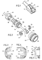
En se référant maintenant aux figures 9 et 10, on va décrire un mode de réalisation du dispositif de fiche plus particulièrement adapté à un cordon optique.Referring now to Figures 9 and 10, we will describe a embodiment of the plug device more particularly adapted to an optical cord.
Sur la figure 9, on a représenté en vue en perspective éclatée les différents éléments constitutifs du dispositif de fiche pour la version optique, ainsi que le cordon optique.In Figure 9, there is shown in exploded perspective view the various components of the plug device for the version optic, as well as the optical cord.
Le cordon optique 60 a son extrémité qui est montée sur un
corps de fiche de cordon 62 et solidarisée à celui-ci par une férule 64. Le
corps de fiche du cordon comporte sur sa face externe un verrou
mécanique 64 qui sera décrit ultérieurement plus en détail.The
Le dispositif de fiche proprement dit comporte tout d'abord un
corps de fiche 66 équipé sur sa face externe d'un écrou de solidarisation
67 avec l'élément conjugué de connexion optique. Le dispositif de fiche
comporte également un adaptateur de fiche 68, 70 destiné à être monté
dans le corps de fiche 66. Le dispositif de fiche comporte également une
pièce tubulaire de connexion 72 dont une première extrémité est destinée
à être rendue solidaire du corps de fiche 66 et dont l'autre extrémité 72b
est destinée à être rendue solidaire d'un presse-étoupe non représenté sur
la figure.The plug device itself comprises first of all a
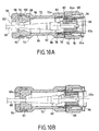
En se référant maintenant à la figure 10A, on va décrire plus en
détail le dispositif de fiche selon l'invention. Le corps de fiche 66
comporte, dans sa face interne 66a un épaulement 74 apte à coopérer
avec un épaulement conjugué 76 ménagé dans la face externe de
l'adaptateur 70, afin d'immobiliser celui-ci en translation vers l'avant.
L'adaptateur 70 peut être immobilisé dans le corps de fiche 66 par la mise
en place d'un système mécanique de verrouillage en translation 78.Referring now to FIG. 10A, we will describe more in
detail the plug device according to the invention. The
Comme on le voit sur cette figure, l'adaptateur 70 comporte un
évidement axial 80 dont le contour permet l'insertion de l'extrémité du
corps de fiche de cordon 62a. Ce profil définit également une rainure
supérieure 80 pour permettre le passage du verrou mécanique 64 du
corps de fiche du cordon optique. Plus précisément, comme le montre la
figure 10A, l'extrémité du verrou 64 comporte une saillie 64a qui peut
coopérer avec un épaulement 82 ménagé dans le passage axial 80 de
l'adaptateur. La coopération de la saillie 64a et de l'épaulement 82 permet
la solidarisation du corps de fiche 62 du cordon avec l'adaptateur. Il faut
ajouter que l'épaulement 82 définit un profil tel que le verrou 64 est
maintenu dans sa position désactivée.As seen in this figure, the
La pièce de liaison 72 comporte, à sa première extrémité 72a,
un taraudage apte à coopérer avec un filetage 86 ménagé à l'extrémité
arrière du corps de fiche 66. La deuxième extrémité 72b de la pièce de
liaison 72 définit un logement 88 de diamètre accru et un épaulement 90
destiné à recevoir un presse-étoupe 92. Ce presse-étoupe 92, au repos,
comme représenté sur la figure 10A, présente un passage axial 94
permettant le libre-passage du corps de fiche 62 du cordon optique. Le
dispositif de fiche comporte, enfin, un écrou de serrage 96 dont le
taraudage 98 peut coopérer avec un filetage externe 100 prévu à
l'extrémité 72b de la pièce de liaison 72. Cet écrou 76 présente un orifice
axial 102 dont le diamètre, ou plus généralement les dimensions sont
suffisantes pour permettre le libre-passage du corps de fiche 62 du cordon
optique.The connecting
L'utilisation du dispositif de fiche destiné à être monté sur la
fiche 62 du cordon optique 60 est le suivant. Dans un premier temps, la
pièce de liaison 72, le presse-étoupe 92 et l'écrou de serrage 96 sont
remontés autour du cordon optique 66. Puis, la partie avant 62a du corps
de fiche 62 est engagé dans le passage axial 80 de l'adaptateur 70, le
verrou mécanique 64 étant abaissé en position inactive. Après l'insertion
du corps de fiche de cordon dans l'adaptateur 70, le verrou 64, grâce à sa
partie en saillie 64a coopérant avec l'épaulement 62, assure la
solidarisation du corps de fiche de cordon et de l'adaptateur. Cet ensemble
est mis en place dans le corps de fiche 70 et immobilisé par l'insertion du
dispositif de verrouillage en translation 78. Dans une étape ultérieure, la
pièce de liaison 72 est vissée sur la partie arrière du corps de fiche 66.
Enfin, l'écrou 66 est vissé sur l'extrémité arrière 72b de la pièce de liaison
72 pour provoquer la déformation du presse-étoupe 92 qui vient ainsi
serrer la face externe 60a du cordon optique 60. On obtient ainsi, non
seulement l'étanchéité du volume interne défini par la pièce de liaison 72
et le corps de fiche 66, mais également la solidarisation mécanique du
cordon optique 60 avec le dispositif de fiche, grâce au serrage mentionné
précédemment. La figure 10B montre le dispositif de fiche monté sur la
fiche 62 du cordon optique 60.The use of the plug device intended to be mounted on the
Claims (9)
ledit corps de presse-étoupe, le presse-étoupe au repos et ladite pièce de liaison définissant un passage interne suffisant pour permettre le passage du corps de la fiche du cordon ;
le vissage du corps du presse-étoupe sur ladite pièce de liaison provoquant la compression dudit presse-étoupe et le serrage dudit presse-étoupe sur le cordon standard.Plug device for standard electrical or optical connection cord provided at one end with a cord plug integral with the cord having a body comprising an external mechanical lock, characterized in that said plug device comprises
said cable gland body, the cable gland at rest and said connecting piece defining an internal passage sufficient to allow the body of the cord plug to pass;
screwing the body of the cable gland onto said connecting piece causing compression of said cable gland and tightening of said cable gland on the standard cord.
Applications Claiming Priority (4)
| Application Number | Priority Date | Filing Date | Title |
|---|---|---|---|
| FR0201321 | 2002-02-05 | ||
| FR0201321A FR2835658B1 (en) | 2002-02-05 | 2002-02-05 | PLUG DEVICE FOR STANDARD ELECTRICAL CONNECTION CORD |
| FR0215512A FR2835657B1 (en) | 2002-02-05 | 2002-12-09 | PLUG DEVICE FOR A STANDARD CORD OF ELECTRIC OR OPTICAL LINK |
| FR0215512 | 2002-12-09 |
Publications (2)
| Publication Number | Publication Date |
|---|---|
| EP1333537A1 true EP1333537A1 (en) | 2003-08-06 |
| EP1333537B1 EP1333537B1 (en) | 2005-04-13 |
Family
ID=26213332
Family Applications (1)
| Application Number | Title | Priority Date | Filing Date |
|---|---|---|---|
| EP03290164A Expired - Lifetime EP1333537B1 (en) | 2002-02-05 | 2003-01-23 | Connector assembly for a standard electrical or optical cable |
Country Status (7)
| Country | Link |
|---|---|
| EP (1) | EP1333537B1 (en) |
| JP (1) | JP4267932B2 (en) |
| AT (1) | ATE293298T1 (en) |
| CA (1) | CA2418376C (en) |
| DE (1) | DE60300484T2 (en) |
| ES (1) | ES2242146T3 (en) |
| FR (1) | FR2835657B1 (en) |
Cited By (11)
| Publication number | Priority date | Publication date | Assignee | Title |
|---|---|---|---|---|
| WO2005026799A1 (en) * | 2003-09-08 | 2005-03-24 | Adc Telecommunications, Inc. | Ruggedized fiber optic connection |
| FR2906089A1 (en) * | 2006-09-18 | 2008-03-21 | Legrand France | HOOD FOR PREDETERMINED INFORMATION NETWORK SHEET, ASSEMBLY AND SYSTEM COMPRISING SAME |
| EP1566674B1 (en) * | 2004-02-19 | 2009-05-06 | Reichle & De-Massari AG | Plug housing of an optical plug connector for industrial environment |
| US7677814B2 (en) | 2007-05-06 | 2010-03-16 | Adc Telecommunications, Inc. | Mechanical interface converter for making non-ruggedized fiber optic connectors compatible with a ruggedized fiber optic adapter |
| US7686519B2 (en) | 2007-06-18 | 2010-03-30 | Adc Telecommunications, Inc. | Hardened fiber optic housing and cable assembly |
| US7722258B2 (en) | 2007-05-06 | 2010-05-25 | Adc Telecommunications, Inc. | Interface converter for SC fiber optic connectors |
| US7744286B2 (en) | 2007-12-11 | 2010-06-29 | Adc Telecommunications, Inc. | Hardened fiber optic connection system with multiple configurations |
| US8770862B2 (en) | 2007-01-24 | 2014-07-08 | Adc Telecommunications, Inc. | Hardened fiber optic connector |
| CN105870698A (en) * | 2016-05-16 | 2016-08-17 | 苏州博豪精密机械有限公司 | Disc shell for plug |
| EP3106904A1 (en) * | 2015-06-16 | 2016-12-21 | Nexans | Optical fibre connector device |
| US10444443B2 (en) | 2013-06-27 | 2019-10-15 | CommScope Connectivity Belgium BVBA | Fiber optic cable anchoring device for use with fiber optic connectors and methods of using the same |
Families Citing this family (11)
| Publication number | Priority date | Publication date | Assignee | Title |
|---|---|---|---|---|
| CN100364182C (en) * | 2005-04-12 | 2008-01-23 | 中航光电科技股份有限公司 | Small volume fast separating RJ 45 electric connector |
| JP4771523B2 (en) * | 2005-08-18 | 2011-09-14 | 株式会社三桂製作所 | hood |
| DE202006011910U1 (en) * | 2005-11-09 | 2007-03-22 | Weidmüller Interface GmbH & Co. KG | Adapter for receiving a plug part |
| DE102007018389B4 (en) * | 2007-04-17 | 2012-01-12 | Mc Technology Gmbh | Connectors |
| JP5892600B2 (en) * | 2012-05-22 | 2016-03-23 | 日本航空電子工業株式会社 | Connector device |
| JP5866734B2 (en) | 2012-12-27 | 2016-02-17 | ヒロセ電機株式会社 | Connector, connector device using the connector, and connector member used for the connector |
| CN103594862A (en) * | 2013-11-25 | 2014-02-19 | 济南中维世纪科技有限公司 | Video camera tail circuit connector |
| EP2960695B1 (en) * | 2014-06-24 | 2020-08-12 | TE Connectivity Nederland B.V. | Connector for a cable and connector assembly |
| US9450338B2 (en) * | 2014-08-06 | 2016-09-20 | Molex, Llc | High speed connector with ruggedized exterior structure and shielding |
| JP6805408B2 (en) * | 2015-10-30 | 2020-12-23 | 群馬県 | Power generation equipment and power generation method using fuel cells |
| KR102395601B1 (en) * | 2021-09-13 | 2022-05-10 | 주식회사유비씨에스 | Waterproof assembly for electric cable |
Citations (3)
| Publication number | Priority date | Publication date | Assignee | Title |
|---|---|---|---|---|
| FR1409281A (en) * | 1964-05-06 | 1965-08-27 | Connector for coaxial cables and shielded cables with one or more conductors | |
| US6257923B1 (en) * | 2000-02-03 | 2001-07-10 | Phillips & Temro Industries Inc. | Dual media connector for a vehicle |
| WO2001057965A1 (en) * | 2000-02-03 | 2001-08-09 | Matsushita Electric Industrial Co., Ltd. | Cable connector |
-
2002
- 2002-12-09 FR FR0215512A patent/FR2835657B1/en not_active Expired - Lifetime
-
2003
- 2003-01-23 AT AT03290164T patent/ATE293298T1/en active
- 2003-01-23 EP EP03290164A patent/EP1333537B1/en not_active Expired - Lifetime
- 2003-01-23 ES ES03290164T patent/ES2242146T3/en not_active Expired - Lifetime
- 2003-01-23 DE DE60300484T patent/DE60300484T2/en not_active Expired - Lifetime
- 2003-02-04 CA CA2418376A patent/CA2418376C/en not_active Expired - Lifetime
- 2003-02-04 JP JP2003026654A patent/JP4267932B2/en not_active Expired - Lifetime
Patent Citations (3)
| Publication number | Priority date | Publication date | Assignee | Title |
|---|---|---|---|---|
| FR1409281A (en) * | 1964-05-06 | 1965-08-27 | Connector for coaxial cables and shielded cables with one or more conductors | |
| US6257923B1 (en) * | 2000-02-03 | 2001-07-10 | Phillips & Temro Industries Inc. | Dual media connector for a vehicle |
| WO2001057965A1 (en) * | 2000-02-03 | 2001-08-09 | Matsushita Electric Industrial Co., Ltd. | Cable connector |
Cited By (31)
| Publication number | Priority date | Publication date | Assignee | Title |
|---|---|---|---|---|
| USRE42522E1 (en) | 2003-09-08 | 2011-07-05 | Adc Telecommunications, Inc. | Ruggedized fiber optic connection |
| US6962445B2 (en) | 2003-09-08 | 2005-11-08 | Adc Telecommunications, Inc. | Ruggedized fiber optic connection |
| WO2005026799A1 (en) * | 2003-09-08 | 2005-03-24 | Adc Telecommunications, Inc. | Ruggedized fiber optic connection |
| EP1566674B1 (en) * | 2004-02-19 | 2009-05-06 | Reichle & De-Massari AG | Plug housing of an optical plug connector for industrial environment |
| FR2906089A1 (en) * | 2006-09-18 | 2008-03-21 | Legrand France | HOOD FOR PREDETERMINED INFORMATION NETWORK SHEET, ASSEMBLY AND SYSTEM COMPRISING SAME |
| WO2008034961A1 (en) * | 2006-09-18 | 2008-03-27 | Legrand France | Cap for pre-determined information network plug, and set and system comprising such a cap |
| US11409057B2 (en) | 2007-01-24 | 2022-08-09 | Commscope Technologies Llc | Hardened fiber optic connector |
| US10877224B2 (en) | 2007-01-24 | 2020-12-29 | Commscope Technologies Llc | Fiber optic adapter |
| US9664862B2 (en) | 2007-01-24 | 2017-05-30 | Commscope Technologies Llc | Hardened fiber optic connector |
| US8770862B2 (en) | 2007-01-24 | 2014-07-08 | Adc Telecommunications, Inc. | Hardened fiber optic connector |
| US8128294B2 (en) | 2007-05-06 | 2012-03-06 | Adc Telecommunications, Inc. | Interface converter for SC fiber optic connectors |
| US8137002B2 (en) | 2007-05-06 | 2012-03-20 | Adc Telecommunications, Inc. | Mechanical interface converter for making non-ruggedized fiber optic connectors compatible with a ruggedized fiber optic adapter |
| US7677814B2 (en) | 2007-05-06 | 2010-03-16 | Adc Telecommunications, Inc. | Mechanical interface converter for making non-ruggedized fiber optic connectors compatible with a ruggedized fiber optic adapter |
| US7722258B2 (en) | 2007-05-06 | 2010-05-25 | Adc Telecommunications, Inc. | Interface converter for SC fiber optic connectors |
| US7686519B2 (en) | 2007-06-18 | 2010-03-30 | Adc Telecommunications, Inc. | Hardened fiber optic housing and cable assembly |
| US10746939B2 (en) | 2007-12-11 | 2020-08-18 | Commscope Technologies Llc | Hardened fiber optic connector compatible with hardened and non-hardened fiber optic adapters |
| US11275220B2 (en) | 2007-12-11 | 2022-03-15 | Commscope Technologies Llc | Hardened fiber optic connector compatible with hardened and non-hardened fiber optic adapters |
| US8414196B2 (en) | 2007-12-11 | 2013-04-09 | Adc Telecommunications, Inc. | Optical fiber connection system with locking member |
| US7744286B2 (en) | 2007-12-11 | 2010-06-29 | Adc Telecommunications, Inc. | Hardened fiber optic connection system with multiple configurations |
| US11867950B2 (en) | 2007-12-11 | 2024-01-09 | Commscope Technologies Llc | Hardened fiber optic connector compatible with hardened and non-hardened fiber optic adapters |
| US9482829B2 (en) | 2007-12-11 | 2016-11-01 | Commscope Technologies Llc | Hardened fiber optic connector compatible with hardened and non-hardened fiber optic adapters |
| US7959361B2 (en) | 2007-12-11 | 2011-06-14 | Adc Telecommunications, Inc. | Hardened fiber optic connection system |
| US8202008B2 (en) | 2007-12-11 | 2012-06-19 | Adc Telecommunications, Inc. | Hardened fiber optic connection system with multiple configurations |
| US7744288B2 (en) | 2007-12-11 | 2010-06-29 | Adc Telecommunications, Inc. | Hardened fiber optic connector compatible with hardened and non-hardened fiber optic adapters |
| US10101538B2 (en) | 2007-12-11 | 2018-10-16 | Commscope Technologies Llc | Hardened fiber optic connector compatible with hardened and non-hardened fiber optic adapters |
| US7942590B2 (en) | 2007-12-11 | 2011-05-17 | Adc Telecommunications, Inc. | Hardened fiber optic connector and cable assembly with multiple configurations |
| US7762726B2 (en) | 2007-12-11 | 2010-07-27 | Adc Telecommunications, Inc. | Hardened fiber optic connection system |
| US10444443B2 (en) | 2013-06-27 | 2019-10-15 | CommScope Connectivity Belgium BVBA | Fiber optic cable anchoring device for use with fiber optic connectors and methods of using the same |
| FR3037666A1 (en) * | 2015-06-16 | 2016-12-23 | Nexans | FIBER OPTIC CONNECTOR DEVICE |
| EP3106904A1 (en) * | 2015-06-16 | 2016-12-21 | Nexans | Optical fibre connector device |
| CN105870698A (en) * | 2016-05-16 | 2016-08-17 | 苏州博豪精密机械有限公司 | Disc shell for plug |
Also Published As
| Publication number | Publication date |
|---|---|
| ES2242146T3 (en) | 2005-11-01 |
| FR2835657B1 (en) | 2004-08-06 |
| CA2418376A1 (en) | 2003-08-05 |
| EP1333537B1 (en) | 2005-04-13 |
| JP2003243108A (en) | 2003-08-29 |
| FR2835657A1 (en) | 2003-08-08 |
| DE60300484D1 (en) | 2005-05-19 |
| DE60300484T2 (en) | 2006-02-23 |
| JP4267932B2 (en) | 2009-05-27 |
| ATE293298T1 (en) | 2005-04-15 |
| CA2418376C (en) | 2010-10-26 |
Similar Documents
| Publication | Publication Date | Title |
|---|---|---|
| EP1333537B1 (en) | Connector assembly for a standard electrical or optical cable | |
| EP2071677B1 (en) | Connector with anti-unlocking system | |
| FR2463526A1 (en) | CABLE CONNECTOR WITH SHEATHED METAL ARMOR | |
| EP1143573A1 (en) | Coaxial connector | |
| EP3038218A1 (en) | Connection assembly with bayonet locking of the connection elements | |
| FR2835658A1 (en) | PLUG DEVICE FOR A STANDARD ELECTRICAL CONNECTION CORD | |
| FR3053801A1 (en) | CONNECTING PLUG TO AN ELECTRONIC EQUIPMENT BOARD PANEL BASE, PROVIDED WITH OPTICAL CABLE ANTI-BREAK MEANS ON WHICH THE PLUG IS MOUNTED | |
| FR2756978A1 (en) | MODULAR CIRCULAR CONNECTOR | |
| FR2713408A1 (en) | Electrical connector. | |
| EP2839546B1 (en) | Quick one-way connection system | |
| EP0592287B1 (en) | Fiberoptical snap connector with overmoulded connector body | |
| EP1111727A1 (en) | Connector plug | |
| EP1727245A2 (en) | Shielded connector for electrical conductors | |
| FR2673331A1 (en) | DEVICE FOR SEALING A CONTACT CAVITY OF AN ELECTRIC OR OPTICAL CONNECTOR. | |
| FR2638905A1 (en) | MULTIPOLAR FEMALE SOCKET FOR CIRCULAR MALE PLUG | |
| FR2703192A1 (en) | Assembly of a plug connector and a coaxial cable plug. | |
| FR2620870A1 (en) | DEVICE FOR SEPARABLE CONNECTION BETWEEN A CONDUCTIVE PIN AND AT LEAST ONE CONNECTING WIRE | |
| EP0821835A1 (en) | Rear connection device for a screened cable electrical connector | |
| EP0895315A1 (en) | Electrical connection device | |
| EP0175033A1 (en) | Scart plug | |
| FR2818450A1 (en) | Nuclear radiation zone remote plugging mechanism having base and arm section with position compensation mechanism having rear section with rotating part forward part cavity pushing. | |
| EP4154360A1 (en) | Improved fool-proofing device, electrical connection assembly comprising said improved fool-proofing device and associated assembly method | |
| FR3028356A1 (en) | ELECTRICAL CONNECTION TERMINAL WITH IMPERDABLE SCREW | |
| EP3823120A1 (en) | Improved electrical connection kit | |
| EP1226630A1 (en) | Electric connector with padlock connection locking |
Legal Events
| Date | Code | Title | Description |
|---|---|---|---|
| PUAI | Public reference made under article 153(3) epc to a published international application that has entered the european phase |
Free format text: ORIGINAL CODE: 0009012 |
|
| AK | Designated contracting states |
Designated state(s): AT BE BG CH CY CZ DE DK EE ES FI FR GB GR HU IE IT LI LU MC NL PT SE SI SK TR |
|
| AX | Request for extension of the european patent |
Extension state: AL LT LV MK RO |
|
| 17P | Request for examination filed |
Effective date: 20031211 |
|
| 17Q | First examination report despatched |
Effective date: 20040316 |
|
| AKX | Designation fees paid |
Designated state(s): AT BE BG CH CY CZ DE DK EE ES FI FR GB GR HU IE IT LI LU MC NL PT SE SI SK TR |
|
| GRAP | Despatch of communication of intention to grant a patent |
Free format text: ORIGINAL CODE: EPIDOSNIGR1 |
|
| GRAS | Grant fee paid |
Free format text: ORIGINAL CODE: EPIDOSNIGR3 |
|
| GRAA | (expected) grant |
Free format text: ORIGINAL CODE: 0009210 |
|
| AK | Designated contracting states |
Kind code of ref document: B1 Designated state(s): AT BE BG CH CY CZ DE DK EE ES FI FR GB GR HU IE IT LI LU MC NL PT SE SI SK TR |
|
| PG25 | Lapsed in a contracting state [announced via postgrant information from national office to epo] |
Ref country code: SK Free format text: LAPSE BECAUSE OF FAILURE TO SUBMIT A TRANSLATION OF THE DESCRIPTION OR TO PAY THE FEE WITHIN THE PRESCRIBED TIME-LIMIT Effective date: 20050413 Ref country code: SI Free format text: LAPSE BECAUSE OF FAILURE TO SUBMIT A TRANSLATION OF THE DESCRIPTION OR TO PAY THE FEE WITHIN THE PRESCRIBED TIME-LIMIT Effective date: 20050413 Ref country code: IE Free format text: LAPSE BECAUSE OF FAILURE TO SUBMIT A TRANSLATION OF THE DESCRIPTION OR TO PAY THE FEE WITHIN THE PRESCRIBED TIME-LIMIT Effective date: 20050413 |
|
| REG | Reference to a national code |
Ref country code: GB Ref legal event code: FG4D Free format text: NOT ENGLISH |
|
| REG | Reference to a national code |
Ref country code: CH Ref legal event code: EP |
|
| REG | Reference to a national code |
Ref country code: IE Ref legal event code: FG4D Free format text: LANGUAGE OF EP DOCUMENT: FRENCH |
|
| REF | Corresponds to: |
Ref document number: 60300484 Country of ref document: DE Date of ref document: 20050519 Kind code of ref document: P |
|
| PG25 | Lapsed in a contracting state [announced via postgrant information from national office to epo] |
Ref country code: DK Free format text: LAPSE BECAUSE OF FAILURE TO SUBMIT A TRANSLATION OF THE DESCRIPTION OR TO PAY THE FEE WITHIN THE PRESCRIBED TIME-LIMIT Effective date: 20050713 Ref country code: GR Free format text: LAPSE BECAUSE OF FAILURE TO SUBMIT A TRANSLATION OF THE DESCRIPTION OR TO PAY THE FEE WITHIN THE PRESCRIBED TIME-LIMIT Effective date: 20050713 Ref country code: BG Free format text: LAPSE BECAUSE OF FAILURE TO SUBMIT A TRANSLATION OF THE DESCRIPTION OR TO PAY THE FEE WITHIN THE PRESCRIBED TIME-LIMIT Effective date: 20050713 |
|
| PG25 | Lapsed in a contracting state [announced via postgrant information from national office to epo] |
Ref country code: HU Free format text: LAPSE BECAUSE OF FAILURE TO SUBMIT A TRANSLATION OF THE DESCRIPTION OR TO PAY THE FEE WITHIN THE PRESCRIBED TIME-LIMIT Effective date: 20050714 |
|
| REG | Reference to a national code |
Ref country code: SE Ref legal event code: TRGR |
|
| GBT | Gb: translation of ep patent filed (gb section 77(6)(a)/1977) |
Effective date: 20050802 |
|
| PG25 | Lapsed in a contracting state [announced via postgrant information from national office to epo] |
Ref country code: PT Free format text: LAPSE BECAUSE OF FAILURE TO SUBMIT A TRANSLATION OF THE DESCRIPTION OR TO PAY THE FEE WITHIN THE PRESCRIBED TIME-LIMIT Effective date: 20050913 |
|
| REG | Reference to a national code |
Ref country code: CH Ref legal event code: NV Representative=s name: MICHELI & CIE INGENIEURS-CONSEILS |
|
| REG | Reference to a national code |
Ref country code: ES Ref legal event code: FG2A Ref document number: 2242146 Country of ref document: ES Kind code of ref document: T3 |
|
| REG | Reference to a national code |
Ref country code: IE Ref legal event code: FD4D |
|
| PG25 | Lapsed in a contracting state [announced via postgrant information from national office to epo] |
Ref country code: LU Free format text: LAPSE BECAUSE OF NON-PAYMENT OF DUE FEES Effective date: 20060131 Ref country code: MC Free format text: LAPSE BECAUSE OF NON-PAYMENT OF DUE FEES Effective date: 20060131 |
|
| PLBE | No opposition filed within time limit |
Free format text: ORIGINAL CODE: 0009261 |
|
| STAA | Information on the status of an ep patent application or granted ep patent |
Free format text: STATUS: NO OPPOSITION FILED WITHIN TIME LIMIT |
|
| 26N | No opposition filed |
Effective date: 20060116 |
|
| PG25 | Lapsed in a contracting state [announced via postgrant information from national office to epo] |
Ref country code: EE Free format text: LAPSE BECAUSE OF FAILURE TO SUBMIT A TRANSLATION OF THE DESCRIPTION OR TO PAY THE FEE WITHIN THE PRESCRIBED TIME-LIMIT Effective date: 20050413 |
|
| PG25 | Lapsed in a contracting state [announced via postgrant information from national office to epo] |
Ref country code: CY Free format text: LAPSE BECAUSE OF FAILURE TO SUBMIT A TRANSLATION OF THE DESCRIPTION OR TO PAY THE FEE WITHIN THE PRESCRIBED TIME-LIMIT Effective date: 20050413 |
|
| REG | Reference to a national code |
Ref country code: FR Ref legal event code: PLFP Year of fee payment: 14 |
|
| REG | Reference to a national code |
Ref country code: FR Ref legal event code: PLFP Year of fee payment: 15 |
|
| REG | Reference to a national code |
Ref country code: FR Ref legal event code: PLFP Year of fee payment: 16 |
|
| PGFP | Annual fee paid to national office [announced via postgrant information from national office to epo] |
Ref country code: SE Payment date: 20211210 Year of fee payment: 20 Ref country code: GB Payment date: 20211206 Year of fee payment: 20 Ref country code: FR Payment date: 20211217 Year of fee payment: 20 |
|
| PGFP | Annual fee paid to national office [announced via postgrant information from national office to epo] |
Ref country code: NL Payment date: 20211216 Year of fee payment: 20 Ref country code: CH Payment date: 20211216 Year of fee payment: 20 Ref country code: BE Payment date: 20211221 Year of fee payment: 20 |
|
| PGFP | Annual fee paid to national office [announced via postgrant information from national office to epo] |
Ref country code: FI Payment date: 20220110 Year of fee payment: 20 Ref country code: DE Payment date: 20211130 Year of fee payment: 20 Ref country code: AT Payment date: 20211229 Year of fee payment: 20 |
|
| PGFP | Annual fee paid to national office [announced via postgrant information from national office to epo] |
Ref country code: TR Payment date: 20220114 Year of fee payment: 20 Ref country code: IT Payment date: 20211213 Year of fee payment: 20 Ref country code: ES Payment date: 20220203 Year of fee payment: 20 Ref country code: CZ Payment date: 20211231 Year of fee payment: 20 |
|
| REG | Reference to a national code |
Ref country code: DE Ref legal event code: R071 Ref document number: 60300484 Country of ref document: DE |
|
| REG | Reference to a national code |
Ref country code: NL Ref legal event code: MK Effective date: 20230122 |
|
| REG | Reference to a national code |
Ref country code: CH Ref legal event code: PL |
|
| REG | Reference to a national code |
Ref country code: BE Ref legal event code: MK Effective date: 20230123 |
|
| REG | Reference to a national code |
Ref country code: GB Ref legal event code: PE20 Expiry date: 20230122 |
|
| REG | Reference to a national code |
Ref country code: SE Ref legal event code: EUG |
|
| REG | Reference to a national code |
Ref country code: AT Ref legal event code: MK07 Ref document number: 293298 Country of ref document: AT Kind code of ref document: T Effective date: 20230123 |
|
| REG | Reference to a national code |
Ref country code: ES Ref legal event code: FD2A Effective date: 20230427 |
|
| PG25 | Lapsed in a contracting state [announced via postgrant information from national office to epo] |
Ref country code: CZ Free format text: LAPSE BECAUSE OF EXPIRATION OF PROTECTION Effective date: 20230123 |
|
| PG25 | Lapsed in a contracting state [announced via postgrant information from national office to epo] |
Ref country code: GB Free format text: LAPSE BECAUSE OF EXPIRATION OF PROTECTION Effective date: 20230122 |
|
| PG25 | Lapsed in a contracting state [announced via postgrant information from national office to epo] |
Ref country code: ES Free format text: LAPSE BECAUSE OF EXPIRATION OF PROTECTION Effective date: 20230124 |