EP1333778B1 - Improved rolling membrane stent delivery system - Google Patents
Improved rolling membrane stent delivery system Download PDFInfo
- Publication number
- EP1333778B1 EP1333778B1 EP01990855A EP01990855A EP1333778B1 EP 1333778 B1 EP1333778 B1 EP 1333778B1 EP 01990855 A EP01990855 A EP 01990855A EP 01990855 A EP01990855 A EP 01990855A EP 1333778 B1 EP1333778 B1 EP 1333778B1
- Authority
- EP
- European Patent Office
- Prior art keywords
- medical device
- sheath
- wall
- delivery system
- rolling
- Prior art date
- Legal status (The legal status is an assumption and is not a legal conclusion. Google has not performed a legal analysis and makes no representation as to the accuracy of the status listed.)
- Expired - Lifetime
Links
Images


Classifications
-
- A—HUMAN NECESSITIES
- A61—MEDICAL OR VETERINARY SCIENCE; HYGIENE
- A61F—FILTERS IMPLANTABLE INTO BLOOD VESSELS; PROSTHESES; DEVICES PROVIDING PATENCY TO, OR PREVENTING COLLAPSING OF, TUBULAR STRUCTURES OF THE BODY, e.g. STENTS; ORTHOPAEDIC, NURSING OR CONTRACEPTIVE DEVICES; FOMENTATION; TREATMENT OR PROTECTION OF EYES OR EARS; BANDAGES, DRESSINGS OR ABSORBENT PADS; FIRST-AID KITS
- A61F2/00—Filters implantable into blood vessels; Prostheses, i.e. artificial substitutes or replacements for parts of the body; Appliances for connecting them with the body; Devices providing patency to, or preventing collapsing of, tubular structures of the body, e.g. stents
- A61F2/01—Filters implantable into blood vessels
- A61F2/0105—Open ended, i.e. legs gathered only at one side
-
- A—HUMAN NECESSITIES
- A61—MEDICAL OR VETERINARY SCIENCE; HYGIENE
- A61F—FILTERS IMPLANTABLE INTO BLOOD VESSELS; PROSTHESES; DEVICES PROVIDING PATENCY TO, OR PREVENTING COLLAPSING OF, TUBULAR STRUCTURES OF THE BODY, e.g. STENTS; ORTHOPAEDIC, NURSING OR CONTRACEPTIVE DEVICES; FOMENTATION; TREATMENT OR PROTECTION OF EYES OR EARS; BANDAGES, DRESSINGS OR ABSORBENT PADS; FIRST-AID KITS
- A61F2/00—Filters implantable into blood vessels; Prostheses, i.e. artificial substitutes or replacements for parts of the body; Appliances for connecting them with the body; Devices providing patency to, or preventing collapsing of, tubular structures of the body, e.g. stents
- A61F2/01—Filters implantable into blood vessels
- A61F2/011—Instruments for their placement or removal
-
- A—HUMAN NECESSITIES
- A61—MEDICAL OR VETERINARY SCIENCE; HYGIENE
- A61F—FILTERS IMPLANTABLE INTO BLOOD VESSELS; PROSTHESES; DEVICES PROVIDING PATENCY TO, OR PREVENTING COLLAPSING OF, TUBULAR STRUCTURES OF THE BODY, e.g. STENTS; ORTHOPAEDIC, NURSING OR CONTRACEPTIVE DEVICES; FOMENTATION; TREATMENT OR PROTECTION OF EYES OR EARS; BANDAGES, DRESSINGS OR ABSORBENT PADS; FIRST-AID KITS
- A61F2/00—Filters implantable into blood vessels; Prostheses, i.e. artificial substitutes or replacements for parts of the body; Appliances for connecting them with the body; Devices providing patency to, or preventing collapsing of, tubular structures of the body, e.g. stents
- A61F2/95—Instruments specially adapted for placement or removal of stents or stent-grafts
- A61F2/958—Inflatable balloons for placing stents or stent-grafts
-
- A—HUMAN NECESSITIES
- A61—MEDICAL OR VETERINARY SCIENCE; HYGIENE
- A61F—FILTERS IMPLANTABLE INTO BLOOD VESSELS; PROSTHESES; DEVICES PROVIDING PATENCY TO, OR PREVENTING COLLAPSING OF, TUBULAR STRUCTURES OF THE BODY, e.g. STENTS; ORTHOPAEDIC, NURSING OR CONTRACEPTIVE DEVICES; FOMENTATION; TREATMENT OR PROTECTION OF EYES OR EARS; BANDAGES, DRESSINGS OR ABSORBENT PADS; FIRST-AID KITS
- A61F2/00—Filters implantable into blood vessels; Prostheses, i.e. artificial substitutes or replacements for parts of the body; Appliances for connecting them with the body; Devices providing patency to, or preventing collapsing of, tubular structures of the body, e.g. stents
- A61F2/95—Instruments specially adapted for placement or removal of stents or stent-grafts
- A61F2/962—Instruments specially adapted for placement or removal of stents or stent-grafts having an outer sleeve
- A61F2/966—Instruments specially adapted for placement or removal of stents or stent-grafts having an outer sleeve with relative longitudinal movement between outer sleeve and prosthesis, e.g. using a push rod
-
- A—HUMAN NECESSITIES
- A61—MEDICAL OR VETERINARY SCIENCE; HYGIENE
- A61F—FILTERS IMPLANTABLE INTO BLOOD VESSELS; PROSTHESES; DEVICES PROVIDING PATENCY TO, OR PREVENTING COLLAPSING OF, TUBULAR STRUCTURES OF THE BODY, e.g. STENTS; ORTHOPAEDIC, NURSING OR CONTRACEPTIVE DEVICES; FOMENTATION; TREATMENT OR PROTECTION OF EYES OR EARS; BANDAGES, DRESSINGS OR ABSORBENT PADS; FIRST-AID KITS
- A61F2230/00—Geometry of prostheses classified in groups A61F2/00 - A61F2/26 or A61F2/82 or A61F9/00 or A61F11/00 or subgroups thereof
- A61F2230/0002—Two-dimensional shapes, e.g. cross-sections
- A61F2230/0028—Shapes in the form of latin or greek characters
- A61F2230/005—Rosette-shaped, e.g. star-shaped
-
- A—HUMAN NECESSITIES
- A61—MEDICAL OR VETERINARY SCIENCE; HYGIENE
- A61M—DEVICES FOR INTRODUCING MEDIA INTO, OR ONTO, THE BODY; DEVICES FOR TRANSDUCING BODY MEDIA OR FOR TAKING MEDIA FROM THE BODY; DEVICES FOR PRODUCING OR ENDING SLEEP OR STUPOR
- A61M25/00—Catheters; Hollow probes
- A61M25/01—Introducing, guiding, advancing, emplacing or holding catheters
- A61M25/0105—Steering means as part of the catheter or advancing means; Markers for positioning
- A61M25/0119—Eversible catheters
Definitions
- This invention relates to a stent delivery and dilatation catheter system, such as the kind used in percutaneous transluminal coronary angioplasty (PTCA) procedures. More particularly, it relates to a stent delivery catheter employing a rolling retractable sheath which may be retracted to release a self-expanding or balloon expandable stent and which may also be employed as a dilatation balloon for expanding a vessel prior to stent delivery.
- PTCA percutaneous transluminal coronary angioplasty
- a guiding catheter is percutaneously introduced into the cardiovascular system of a patient and advanced through the aorta until the distal end is in the ostium of the desired coronary artery. Using fluoroscopy, a guide wire is then advanced through the guiding catheter and across the site to be treated in the coronary artery. A balloon catheter is advanced over the guide wire to the treatment site. The balloon is then expanded to reopen the artery.
- the catheter may have a guide wire lumen which is as long as the catheter (such as with an over the wire catheter - OTW) or it may be a rapid exchange catheter wherein the guide wire lumen is substantially shorter than the catheter. Alternatively, a fixed wire balloon catheter could be used. This device features a guide wire which is affixed to the catheter and cannot be removed.
- a physician can implant an intravascular prosthesis, or a stent, for maintaining vascular patency inside the artery at the lesion.
- the stent may either be a self-expanding stent or a balloon expandable stent.
- the stent is often delivered on a balloon and the balloon is used to the expand the stent.
- the self-expanding stents may be made of shape memory materials such as Nitinol or constructed of other metals but of a design which exhibits self expansion characteristics.
- a stent and an optional balloon are positioned at the distal end of the catheter, around a core lumen.
- the stent and balloon are held down and covered by a sheath or sleeve.
- the sheath or sleeve is retracted to expose the stent.
- the stent is free to self-expand or be expanded with a balloon.
- a number of sheath designs are known in the art including those disclosed in US 4,732,152 to Wallsten ('152), US 4,848,343 to Wallsten ('343), US 4,875,480 to Imbert , US 5,662,703 to Yurek et al. ('703), US 5,690,644 to Yurek ('644) and WO 94/15549 , disclose using a sleeve formed of a doubled-over section of membrane to compress and contain the stent.
- Wallsten'152 and Wallsten '343 disclose the use of lubricants on the interior walls of the membrane. Moreover, fluid may be introduced into the chamber that is formed, in part, by the walls of the doubled-over membrane.
- the Imbert device contains small holes in the sleeve to allow for the expulsion of gas therefrom upon the introduction of a fluid into the region between the inner and outer walls.
- the holes are not sized to allow for fluid flow therethrough.
- Yurek '703 discloses a stent that is retained distal to the inner tube by a folded over sheath.
- the outer layer of the sheath although not the inner layer, is disclosed as being porous.
- the Yurek '644 patent and WO 94/15549 disclose a catheter in which a stent is mounted on an inner tube and retained by a double walled hose having micro pores in the outer wall of the hose. The micro pores allow for the flow of fluid therethrough.
- the Yurek catheter is of the rapid-exchange design.
- US 5,445,646 to Euteneuer et al. discloses a stent delivery apparatus comprising a single layer sheath retaining sleeve means for retaining the stent in its delivery configuration attached to a slipping sleeve means for releasing the stent to self-expand.
- the slipping sleeves may be activated hydraulically by delivering a fluid to the area in between the inner and outer layers of the slipping sleeve.
- US-A-6059813 discloses a medical device delivery system according to the preamble of claim 1.
- the problem of the invention is to improve the known delivery systems, in particular to provide a medical device delivery system with a rolling retractable sheath in which the frictional interactions between the inner and outer walls of the sheath are reduced without requiring hydraulic activation.
- a rolling membrane eliminates the problem of sliding friction that is common with sliding sheaths as the rolling membrane, literally, rolls off of the stent. This, in turn, results in a lesser likelihood of the stent being damaged as the sheath is removed from over it. It is also desirable to provide a dual function stent delivery system wherein the sheath may function as an expansion balloon as well as a stent retaining sheath.
- the present invention addresses these needs in its various embodiments as described below.
- the present invention provides a medical device delivery system which comprises an inner tube having a medical device mounting region at the distal region for concentrically mounting a medical device thereon and a rolling retractable sheath which may operates as a dilatation balloon and which retains a medical device on the inner tube and a retraction device.
- the rolling retractable sheath which includes a rolling double walled member, may be formed of a single member folded over on itself or of two different members joined together and folded over on itself. It is disposed concentrically about the inner tube.
- the inner wall of the double walled member is attached to the inner tube proximal to the medical device mounting region and the outer wall of the double walled member is attached to a retraction device.
- the inner wall preferably has a greater tendency to rollingly move upon the application of a rolling force than the outer wall.
- An open ended chamber is formed by the inner and outer walls of the sheath.
- the open end of the chamber narrows at a point where it is in fluid communication with a proximally extending inflation lumen.
- the chamber is filled with a fluid in order to cause at least the outer wall of the sheath to expand outward from the catheter.
- the various walls of the catheter may be constructed to allow the outer wall to have predetermined inflation properties which may differ from those of the inner wall.
- the inner tube has a medical device mounting region at the distal region for concentrically mounting a medical device thereon.
- the sheath is retractable from a delivery position to a release position. In the delivery position, the sheath covers at least a portion of the medical device mounting region while in the release position, the sheath no longer covers the medical device mounting region.
- the retraction device which is operably connected to the rolling retractable sheath for retraction of the retractable sheath, moves the outer wall in a proximal direction relative to the inner wall so that the sheath no longer covers the medical device mounting region.
- the retraction device may used to position the sheath and to assist in preventing the sheath from moving off of the stent prior to delivery of the stent.
- the invention is directed to a medical device such as those described above in which the inner wall of the rolling retractable sheath is formed of at least a first material and the outer wall is formed of at least a second material different from the first material.
- the inner and outer walls may be adhesively bonded together, mechanically joined together or otherwise joined to each other.
- the inner and outer walls may be constructed of a first material which rolls on retraction of the sheath and a second material which does not roll on retraction.
- the second material has a higher hoop strength than the first material.
- the outer wall material has a higher tensile strength than the inner wall material of the sheath.
- the outer wall exhibits a higher degree of longitudinal stiffness than the inner wall.
- the outer wall is more compliant than the inner wall.
- the outer wall exhibits a higher flexural modulus than the inner wall.
- the thickness of the inner and outer walls may also differ, further contributing to the desired properties of the walls.
- the inner and outer walls are made of the same material, the inner wall being thinner than the outer wall.
- the inner wall is thin enough to allow the inner wall to roll while the outer wall is sufficiently thick to resist rolling and prevent unwanted movement of the stent.
- the thickness of the outer wall will be at least 1.5 times the thickness of the inner wall, more desirably, the outer wall will be at least 4 times the thickness of the inner wall.
- a lubricant may, optionally, applied to at least a portion of the inner wall and/or outer wall.
- a pull-collar mounted at the distal end of the catheter in conjunction with a pull wire may be employed as part of the retraction device.
- the invention is further directed to a stent delivery device comprising any of the above-described medical device delivery systems with a stent mounted on the medical device mounting region of the inner tube.
- Other device that may be delivered by the above described systems include grafts and vena cava filters.
- An example is also directed to a method of delivering a medical device to a desired bodily location.
- the method comprises the steps of providing medical device delivery system as claimed and a medical device, mounting the medical device on the medical device mounting region of one of the described medical device delivery systems, percutaneously inserting the medical device delivery system in a bodily lumen containing a bodily fluid, the bodily fluid optionally passing through the sheath so as to prime the medical device delivery system, traversing the bodily lumen until the desired bodily location is reached, optionally inflating the sheath to pre-dilate the body lumen, retracting the rolling retractable sheath proximally so as to expose the medical device and withdrawing the medical device delivery system from the bodily lumen.
- the medical device is a stent, optionally self-expanding, although other devices including grafts and vena cava filters may be similarly delivered.
- the invention is directed to a medical device delivery system comprising an inner tube having a medical device mounting region at the distal region for concentrically mounting a medical device thereon, a rolling retractable sheath and a retraction device for retracting the rolling sheath.
- the rolling retractable sheath serves to retain a medical device around for about the inner tube.
- the rolling retractable sheath is formed of a double walled member forming an open chamber between the walls which is inflatable by being in fluid communication with a proximally extending inflation lumen.
- the sheath is disposed concentrically about the inner tube.
- the rolling sheath is secured, directly or indirectly via a bumper or other securement device, to the inner tube proximal of the medical device mounting region.
- the rolling sheath is attached to a retraction device.
- the term "medical device mounting region” is intended to apply to a region of an inner tube on which a medical device resides as well as a region of an inner tube over which a medical device resides.
- An example of the former is a region of an inner tube to which a stent is crimped.
- An example of the latter is a region over which a self expanding stent resides.
- mounting a medical device on an inner tube it is intended to include both mounting the device on and mounting the device over the inner tube.
- Fig. 1a shows a medical device delivery system in general at 110.
- a medical device mounting region 118 At the distal end of inner tube 114 is a medical device mounting region 118.
- Inner tube 114 is desirably made of flexible, but incompressible construction such as a polymer encapsulated braid or coil.
- the flexibility of the braid/coil construction allows the medical device delivery system to navigate through body lumens and the incompressibility of the braid/coil aids in maintaining the integrity for the catheter and aids in deployment accuracy when the retractable rolling sheath is being retracted during stent release.
- the braid/coil may be comprised of stainless steel encased in a polymer such as Polyimide with an inner layer of Teflon TM .
- the inner tube need not, however, be made of incompressible materials. Flexible and compressible materials such as polyethylene may also be used.
- Covering medical device mounting region 118 is a rolling retractable sheath 122 for retaining a medical device on the inner tube.
- the medical device delivery system further comprises a retraction means for retracting the rolling retractable sheath.
- Rolling retractable sheath 122 disposed concentrically about inner tube 114, is formed of a single material folded over on itself. As such, at least a portion of the sheath is double-walled.
- Inner wall 130 of sheath 122 is attached to inner tube 114 at a region 134 proximal to medical device mounting region 118.
- Outer wall 138 of sheath 122 is attached to retraction device 126 at region 142 of the retraction device.
- a sealed chamber 146 is formed by inner wall 130 and outer wall 138 of the sheath, at least a portion 150 of the inner tube and the portion 154 of the retraction device which is distal to the region of attachment 142 of the outer wall to the retraction device.
- the sheath is retractable from a delivery position, as shown in Fig. 1a , to a release position as shown in Fig. 2 .
- the sheath covers at least a portion of the medical device mounting region while in the release position, the sheath no longer covers the medical device mounting region.
- a retraction device 126 is attached to rolling retractable sheath 122.
- Retraction device 126 comprises a pull collar 127 operably attached to a pull-wire 128 which extends to the proximal end of the medical device delivery system.
- Pull collar 127 is a ring-shaped member of stainless steel or preferably of a radio-opaque material such as gold affixed to distal outer tube 178 by an appropriate adhesive such as a urethane.
- the distal outer tube is, in turn, connected to the rolling sheath.
- the pull wire may be made of suitable material including stainless steel.
- the medical device delivery system optionally, further comprises a collapsible midshaft sheath, as shown in Fig. 1a and in more detail in Fig. 1b .
- the distal end of proximal outer tube 170 is attached, desirably adhesively bonded, to an accordion-like collapsible midshaft sheath 174.
- the distal end of collapsible midshaft sheath 174 is, in turn, attached, desirably adhesively bonded, to distal outer tube 178.
- Pull collar 127 is attached to the distal end of distal outer tube 178.
- the retraction device moves the outer wall in a proximal direction relative to the inner wall so that the sheath no longer covers the medical device mounting region. In so doing, collapsible midshaft sheath 174 decreases in length. Additional information about the collapsible midshaft sheath made be found in US Patent 5,534,007 to St. Germain and Olson .
- Rolling retractable sheath 122 is retractable from a delivery position as shown in Fig. 1 , to a release position as shown in Fig. 2 .
- the medical device delivery system further comprises an optional tip 162 mounted at the distal end of inner tube 114 abutting retractable sheath 122 Tip 162 may be affixed to the inner tube by an adhesive such as H.B. Fuller 3507, an urethane adhesive, or the like.
- a self-expanding stent 158 mounted on medical device mounting region 1218 of the system.
- Stent 158 is contained in medical device containment area 166.
- sealed chamber 146 is not in fluid communication with any part of the delivery system proximal of the sheath, the sealed chamber may be coated or filled with a lubricating substance to reduce the friction because the inner and outer walls of the sheath without any direct interaction between the lubricating substance and a bodily fluid.
- the medical device delivery system shown generally at 210 comprises an inner tube 214 with a medical device mounting region 218 is a rolling retractable sheath 222 for retaining a medical device on the inner tube. Attached to rolling retractable sheath 222 is a retraction device 226 for retracting the sheath.
- rolling retractable sheath 222 is formed of a single material folded over on itself.
- Inner wall 230 of sheath 222 is attached to inner tube 214 at a region 234 proximal to medical device mounting region 218.
- Outer wall 238 of sheath 222 is attached to retraction device 226 at region 242 of the retraction device.
- retraction device 226 includes proximal outer tube 270 attached to retractable sheath 274 which in turn is attached to distal outer tube 278.
- Pull collar 227 is attached to the distal end of the distal outer tube 278 and pull wire 228 extends proximally from pull collar 227.
- FIG. 3 Also shown in the embodiment of Fig. 3 is an optional self-expanding stent 258 mounted on medical device mounting region 218 of the system. Stent 258 is contained in medical device containment area 266.
- sheath 274 in the unretracted position is shown as being double walled over the entire length of stent 258, the double walled region of the sheath need not extend over the entire length of the stent but may extend over only a fraction of the stent.
- Using a sheath whose doubled over region in the unretracted position is of reduced length may prove advantageous in that the overall length of the sheath in the retracted position is also reduced thereby resulting in a delivery system with a smaller profile over a greater length. It is desirable for the double over region to extend over at least one-half of the stent and more desirable to extend over at least one quarter or one eighth of the stent.
- the chamber 246 formed by inner wall 230 and outer wall 238 of the sheath and at least a portion of the inner tube 250 and a portion of the retraction device 226 may be sealed.
- the medical device delivery system further comprises an optional tip 262 mounted at the distal end of inner tube 214 abutting retractable sheath 222.
- the rolling sheath 222 is made, at least in part, of a porous material capable of allowing fluid therethrough.
- Suitable porous materials include expanded polytetrafluoroethylene (ePTFE) and polyester. Desirably, the materials will have a pore size ranging from 0.01 mm to 5.0 mm.
- the porosity of the inner and outer walls allows medical device containment area 266 to be flushed free of air by fluid traveling through the inner and outer walls and into the medical device containment area.
- the medical device delivery system shown generally at 310, is constructed similarly to the embodiment of Fig. 2 , differing in that rolling sheath 322 has an inner wall 330 and an outer wall 338, the inner wall formed of at least a first material, and the outer wall formed of at least a second material different from the first material.
- the delivery system of Fig. 4 further differs from the delivery system of Fig. 3 in that inner tube 318 is comprised of part of a dual lumen tube.
- the other lumen 382 of the dual lumen tube provides for a flush lumen in fluid communication with stent chamber 386.
- retraction device 326 includes proximal outer tube 370 attached to retractable sheath 374 which in turn is attached to distal outer tube 378.
- Pull collar 327 is attached to the distal end of the distal outer tube 378 and pull wire 328 extends proximally from pull collar 327.
- the medical device delivery system further comprises an optional tip 362 mounted at the distal end of inner tube 314 abutting retractable sheath 322.
- a self-expanding stent 358 mounted on medical device mounting region 318 of the system.
- Stent 358 is contained in medical device containment area 366.
- Optional bumper 372 is also shown.
- Bumper 372 may be of polyethylene and is affixed to the inner tube by an adhesive such as H.B. Fuller 3507.
- the medical device delivery system may comprise marker bands (not shown) included to aid in positioning and maybe affixed to the inner tube by adhesive such as Loctite 4011.
- Inner wall 330 and outer wall 338 may be adhesively bonded together, heat welded, sutured or otherwise mechanically joined together.
- Suitable adhesives include urethane and epoxy.
- first and second materials the materials must be chosen such that the material of the inner wall will have a greater tendency to rollingly move upon the application of a rolling force than the outer wall.
- the relative tendency of materials to rollingly move may be tested by taking a strip of a given material, immobilizing one end of the strip, folding a small portion of the opposite end of the material over on itself and measuring the force in the longitudinal direction necessary to initiate rolling motion of the folded over end of the material.
- a first material that rolls on retraction of the sheath will be selected along with a second material that does not roll on retraction.
- the second material will have a higher hoop strength than the first material.
- the outer wall of the sheath in the unretracted position has a higher tensile strength than the inner wall of the sheath.
- the outer material is made of high density polyethylene (HDPE) and the inner material is made of poly(block-amide-block-ether) ester materials such as PEBAX TM brand polymers manufactured by Atochem North America, Inc. (Philadelphia PA).
- the materials may also be chosen so that the outer layer is resistant to creep in the radial direction and/or resistant to compression or expansion in the longitudinal direction while the inner layer is flexible, both radially and longitudinally.
- the extra strength of the outer layer prevents the sheath from creeping under the force of a self-expanding stent contained by the sheath and helps to ensure that the stent will not deploy until the system is actuated.
- the flexibility of the inner layer allows the sheath to be rolled in on itself.
- the materials may also be chosen such that the outer layer is made of a material of higher tensile strength, flexural modulus and/or higher hoop strength than the inner layer.
- the materials may also be chosen such that the outer layer has a higher degree of longitudinal stiffness than the inner layer.
- the rolling retractable sheath is characterized by the presence of an outer wall of a first thickness and an inner wall of a second thickness.
- the first thickness may be greater or less than the second thickness.
- the material of the outer wall must have a flexural modulus and/or tensile strength and/or hoop strength and/or longitudinal stiffness in excess of that of the inner material so that the relative thicknesses of the layers is offset by the relative material properties of the walls.
- the invention also contemplates a medical device delivery system having a rolling retractable sheath where the inner wall of the retractable sheath is flexible enough to roll while the outer wall of the retractable sheath is stiff enough to prevent unwanted movement of the stent and the outer and inner walls are made of the same material.
- the property differentiation results from the inner wall being thinner than the outer wall. This may be accomplished, for example, by providing a tapered tube folded over on itself.
- the invention also contemplates the use of porous materials for the first and/or second materials. Where both materials are porous, the medical device delivery system will be self-priming. Suitable porous materials for use in this embodiment include PTFE, polyester and silicone.
- thermoplastic elastomers such as polyurethane, polyethylene, polyester, polyvinyl chloride, nylon and their block copolymers as well as PEBAX TM polymers for the double walled sheath.
- suitable materials include fluoropolymers, non-compliant polyethylene terephthalate (PET), polyamide and polyolefin copolymers such as SURLYN TM .
- the materials for use in the double walled sheaths of the invention will exhibit high strength even for wall thicknesses as small as 2.54/1000's of an cm (1/1000's of an inch).
- Suitable materials include uniaxially oriented films such as are formed by blow molding.
- a suitable lubricant may be selectively applied to at least a portion of the inner and/or outer walls.
- the invention also contemplates completely covering the inner and outer walls with a lubricant.
- Suitable lubricants include silicones, polyvinyl pyrrolidone, and PPO (polypropylene oxide). Additionally, BioSlide TM coating produced by SciMed made be used as well.
- BioSlide TM is a hydrophilic, lubricious coating comprising polyethylene oxide and neopentyl glycol diacrylate polymerized in a solution of water and isopropyl alcohol in the presence of a photoinitiator such as azobisisobutronitrile.
- a photoinitiator such as azobisisobutronitrile.
- Other hydrogels such as PEG (polyethylene glycol), PEO/PPO/PEO-polyethylene oxide/polypropylene oxide/polyethylene oxide triblock polymer manufactured by ASF or PPO/PEO/PPO may also be used.
- Fluids, desirably bio-compatible may also be used as lubricants in the practice of the invention. The presence of a fluid between the inner and outer walls of the sheath prevents the inner and outer walls from contacting one another thereby reducing the friction between the walls.
- Friction between the inner and outer walls may also be reduced by altering the design of the rolling sheath.
- the rolling sheath shown in the above figures is reproduced in Fig. 5a .
- Inner wall 430 and outer wall 438 are substantially parallel to one another. Other, lower friction geometries are also contemplated such as that shown at 422 in Fig. 5b .
- Inner wall 430 is disposed at an oblique angle relative to outer wall 438 such that the distance between the inner wall and the outer wall increases with the distance from the fold 423 in the rolling sheath. The increased separation between the walls reduces the contact between the walls and hence the frictional interactions between the walls.
- flush lumen may suitably be used in any of the other embodiments disclosed herein.
- the invention also contemplates the use of other suitable retraction means as are known in the art including slidably sealed retractable sheaths and midshaft seals as described in US Patent 5772669 , and US Patent 5957930 .
- Other contemplated retraction means include sheaths activated directly by pull-collars as described in US Patent 5957930 ; and screw-like retraction devices as described in US Patent 5,201,757 to Heyn et al. all.
- the rolling retractable sheath may be a full length sheath which extends to the proximal end of the medical device delivery system.
- the medical device delivery system comprises a rolling retractable sheath 522 closed on itself.
- the delivery system comprises an inner tube 514 having a medical device mounting region 518 at the distal region for concentrically mounting a medical device thereon.
- the proximal end of rolling retractable sheath 522 is secured to the inner tube via optional bumper 572 at a location 523 proximal to medical device mounting region 518. If optional bumper 572 is not present, rolling retractable sheath 522 may be secured directly to the inner tube.
- Rolling retractable sheath 522 contains stent 558 which is mounted over or around distal end 518 of inner tube 514.
- the stent may alternatively be mounted directly on the inner tube.
- the distal end of rolling retractable sheath 522 is attached to a retraction device 526.
- Adhesives such as polyurethane, epoxy, cyanoacrylates and acrylics or other suitable means of attachment including heat welding, suturing or other forms of mechanically joining may be used to affix the rolling sheath to the retraction device.
- retraction device 526 is an outer sheath which covers the rolling sheath and extends in a proximal direction. Rolling retractable sheath 522 may be retracted by pulling outer sheath 526 in a proximal direction.
- Rolling retractable sheath 522 may optionally be provided with longitudinally oriented ribs to provide resistance to buckling.
- a tapered sheath design similar to that shown in Fig. 5b and closed on itself at both ends may also be used in order to prevent buckling of the sheath upon retraction of the sheath.
- Outer sheath 526 may be a full length sheath which extends all the way to the proximal end of the medical device delivery system or alternatively may extend proximally for only a portion of the delivery system. In the latter case, outer sheath 526 may be used in conjunction with a collapsible midshaft sheath as disclosed above.
- the outer sheath may be made of a homogeneous polymer or a composite. Suitable materials include polyolefin copolymers, Pebax TM , polyurethane, nylon, polyethylene, polyesters and other thermoplastic elastomers. It is desirable for the outer sheath to be flexible, but radially non-compliant.
- the outer sheath may be formed of a polymer encapsulated braid or coil.
- the braid/coil may be formed of stainless steel encased in a polymer such as Polyimide with an inner layer of Teflon TM .
- slits may be made in the tube to increase the flexibility of the tube without sacrificing radial strength.
- the outer sheath may be made from a material which is chosen so as to provide support for the rolling sheath as it is retracted, to prevent distention of the rolling sheath.
- a suitable retraction device is a collar and pull wire.
- a pull collar as disclosed above, may be affixed to the distal end of the rolling retractable sheath.
- a pull wire extending proximally from the pull collar may then be used to retract the rolling sheath.
- the pull wire may enter the inner tube at a point proximal to the stent and preferably at a point which is at a distance of at least one rolling retractable sheath proximal to the stent so as not interfere with the operation of the rolling sheath.
- the rolling sheath may be formed of one material or may be formed of several materials joined together. Because, however, both the inner and outer walls of the rolling sheath roll in this embodiment, it is desirable that both the outer and inner walls be made of the same materials.
- lubricants may be used in the interior of the rolling retractable sheath in the embodiment of Fig. 6 to reduce the frictional interactions between the walls of the sheath and to facilitate rolling. Any of the above lubricants may be employed.
- a further advantage of the medical device delivery system shown in Fig. 6 is the reduced length of the rolling sheath upon retraction as compared with rolling sheaths that are not closed on themselves as in the previous embodiments. Whereas the length of a rolling sheath closed on itself is unchanged upon retraction of the sheath, standard rolling sheaths may double in length upon retraction as the sheath is fully extended and ceases to form a double layer.
- the reduced length of the fully retracted rolling sheath which is closed on itself as compared with a standard rolling sheath allows for a medical device delivery system of lower profile over a greater portion of the distal end of the system.
- the example is directed to medical device delivery systems comprising an inner tube 614 with a medical device mounting region 618 at the distal region for concentrically mounting a medical device 658 thereon, a rolling retractable sheath 622 for retaining medical device 658 on medical device mounting region 618 and a retraction device (not shown) for retracting the rolling sheath.
- medical device mounting region 618 is characterized by a medical device mounting length, L m .
- Rolling retractable sheath 622 is disposed about inner tube 614 with the proximal end of rolling sheath 622 secured to inner tube 614 proximal of the medical device mounting region 618.
- Rolling sheath 622 in an unretracted state is characterized by a first length, L 1 , as defined by the distance between the proximal-most point on the unretracted sheath and the distal-most point on the unretracted sheath.
- Rolling sheath 622 in the unretracted state is further characterized by a double wall length L d as measured by the length over which the sheath forms a double wall. Rolling sheath 622 upon retraction, as shown in Figs.
- rolling sheath 622 is operably connected to a retraction device (not shown) for retraction of the rolling sheath.
- the delivery system is further characterized in that the difference between the second length L 2 and the first length L 1 is less than the medical device mounting length L m .
- the difference between the second length L 2 and the first length L 1 will be less than half of the medical device mounting length. More desirably, the difference between the second length L 2 and the first length L 1 will be substantially equal to zero as in Figs. 7c and 7d where the rolling sheath is closed on itself or where the sheath has a very short double walled region L d as in Figs. 7a and 7b . It is also desirable for the second length L 2 to be less than twice the first length L 1 and/or less than twice the medical device mounting length L m .
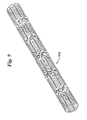
- the above-disclosed inventive medical devices are used for delivery of self-expanding stents such as that shown in Fig. 8 at 758
- other stents may also be used in conjunction with this invention including mechanically expandable stents such as balloon expandable stents.
- a balloon is provided in the medical device mounting region of the delivery device and a stent mounted thereon.
- Suitable inflation means as are known in the art, such as an inflation lumen, are provided.
- Other suitable medical device for use with the present invention include grafts or stents/grafts, including that shown in Fig. 9 at 858 and vena cava filters, including that shown in Fig. 10 at 958.
- the invention is not intended to be so limited.
- the invention is directly more generally at a medical device delivery system with a medical device mounted about the medical device receiving region, whether or not the medical device is concentric with the inner tube.
- the term 'mounted' as used in the context of the medical device being mounted on the medical device receiving region is intended to include the case where the medical device is in contact with the medical device receiving region of the inner tube as well as the case where the medical device surrounds at least a portion of the medical device mounting region although it is not actually in contact with said region of the inner tube.
- An example of the former is as a stent crimped onto the inner tube while an example of the latter is a self expanding stent which is maintained in place about the inner tube by a sheath.
- the rolling retractable sheath has been referred to as being disposed concentrically about the inner tube, the invention further contemplates the possibility of the rolling retractable sheath being disposed non-concentrically about the inner tube.
- the present example is also directed to methods of delivering a medical device, such as those described above, to a desired bodily location using any of the devices described herein.
- One such method comprises the steps of providing one of the above-described medical device delivery systems and a medical device and mounting the medical device on the medical device mounting region of the system.
- the medical device delivery system is then percutaneously inserted in a bodily lumen containing a bodily fluid.
- the sheath is made of a porous material, bodily fluids may pass through the sheath so as to self-prime the medical device delivery system.
- the medical device is traversed through the bodily lumen until the desired bodily location is reached at which point the rolling retractable sheath is retracted proximally so as to expose the medical device.
- the medical device delivery system is then withdrawn from the bodily lumen.
- this method may be used to deliver a self-expanding stent to a desired bodily location. Upon retraction of the sheath, the stent self-expands and the delivery system is then withdrawn.
- Figure 6 shows one such suitable stent 458 for use with the present invention.
- Other medical devices such as balloon or mechanically expandable stents may similarly be delivered and deployed. In this case of the balloon expandable stent, the delivery system must be modified to include a balloon mounted over the inner tube and under at least a portion of the stent and to further include suitable tubes to allow for inflation of the balloon, as is well known in the art.
- Other medical devices that may be delivered by using the above method include grafts and vena cava filters.
- a retraction device 126 is attached to rolling retractable sheath 122.
- Retraction device 126 comprises a pull collar 127 operably attached to a pull-wire 128 which extends to the proximal end of the medical device delivery system.
- Pull collar 127 is affixed to distal outer tube 178.
- the distal outer tube is, in turn, connected to the rolling sheath.
- the pull wire may be made of suitable material including stainless steel.
- chamber 146 is not sealed by the presence of pull collar 127 between the outer tube 128 and inner tube 114.
- chamber 146 is in fluid communication with inflation lumen 200.
- the sheath 122 may be utilized as a dilation balloon.
- the sheath 122 In order to effectively utilize the sheath 122 as a dilation balloon prior to stent delivery, the sheath must be prevented from retraction off of the stent 158 during inflation of chamber 146. During inflation of the sheath 122, retraction device 126 acts as a stiffening member to hold the sheath 122 in place thereby preventing any proximal movement or retraction of the sheath 122. The sheath 122 may be inflated prior to stent delivery in order to clear protrusions of plaque or other stenosis.
- the chamber 146 may be evacuated of fluid via the inflation lumen 200 and the retraction device 126 drawn proximally in order to pull back the sheath of the stent 158.
- the retraction device 126 may be relaxed to allow the presence of the fluid within chamber 146 to draw back the sheath in the manner previously described above.
- the sheath is preferably constructed so that the outer wall 138 of the sheath is be composed of a higher compliance material than the inner wall 130.
- inner wall 130 may be positioned immediately adjacent to stent 158 with no space provided therebetween.
- sheath 122 When the sheath 122 is used as a dilation balloon the sheath must be at least partially composed of a suitable balloon or expandable material. Preferably, sheath 122 is at least partially composed of polyethylene or polyolefin copolymers such as SURLYN TM .
- the inner tube extends proximally to a manifold and a guide wire may be inserted into the inner tube from the proximal end, the guide wire extending to the distal end of the system.
- the medical device delivery system may then ride on the guidewire.
- the guidewire is fixedly attached to the medical device delivery system.
- a fixed-wire delivery system is described in U.S. 5,702,364 to Euteneuer et al. , and may be suitably modified for use with the inventive medical device delivery system.
- a rapid exchange delivery system is described in U.S. 5,534,007 to St. Germain et al. , and may be suitably modified for use with the inventive medical device delivery system.
- the rapid-exchange version may be realized by having the inner tube terminate in a guide wire port in a location along the system distal to the proximal end of the system to allow for insertion of a guide wire therein.
- only a portion of the medical device delivery system rides on a guidewire.
- the usable length of the medical device delivery system is approximately 135 cm.
- the distance from where the guide wire accesses the inner tube to the distal tip will be approximately 5 cm to 45 cm.
Abstract
Description
- This invention relates to a stent delivery and dilatation catheter system, such as the kind used in percutaneous transluminal coronary angioplasty (PTCA) procedures. More particularly, it relates to a stent delivery catheter employing a rolling retractable sheath which may be retracted to release a self-expanding or balloon expandable stent and which may also be employed as a dilatation balloon for expanding a vessel prior to stent delivery.
- In typical PTCA procedures, a guiding catheter is percutaneously introduced into the cardiovascular system of a patient and advanced through the aorta until the distal end is in the ostium of the desired coronary artery. Using fluoroscopy, a guide wire is then advanced through the guiding catheter and across the site to be treated in the coronary artery. A balloon catheter is advanced over the guide wire to the treatment site. The balloon is then expanded to reopen the artery. The catheter may have a guide wire lumen which is as long as the catheter (such as with an over the wire catheter - OTW) or it may be a rapid exchange catheter wherein the guide wire lumen is substantially shorter than the catheter. Alternatively, a fixed wire balloon catheter could be used. This device features a guide wire which is affixed to the catheter and cannot be removed.
- To help prevent arterial closure, repair dissection, or prevent restenosis, a physician can implant an intravascular prosthesis, or a stent, for maintaining vascular patency inside the artery at the lesion. The stent may either be a self-expanding stent or a balloon expandable stent. For the latter type, the stent is often delivered on a balloon and the balloon is used to the expand the stent. The self-expanding stents may be made of shape memory materials such as Nitinol or constructed of other metals but of a design which exhibits self expansion characteristics.
- In certain known stent delivery catheters, a stent and an optional balloon are positioned at the distal end of the catheter, around a core lumen. The stent and balloon are held down and covered by a sheath or sleeve. When the distal portion is in its desired location of the targeted vessel the sheath or sleeve is retracted to expose the stent. After the sheath is removed, the stent is free to self-expand or be expanded with a balloon.
- A number of sheath designs are known in the art including those disclosed in
US 4,732,152 to Wallsten ('152),US 4,848,343 to Wallsten ('343),US 4,875,480 to Imbert ,US 5,662,703 to Yurek et al. ('703),US 5,690,644 to Yurek ('644) andWO 94/15549 - Wallsten'152 and Wallsten '343 disclose the use of lubricants on the interior walls of the membrane. Moreover, fluid may be introduced into the chamber that is formed, in part, by the walls of the doubled-over membrane.
- The Imbert device contains small holes in the sleeve to allow for the expulsion of gas therefrom upon the introduction of a fluid into the region between the inner and outer walls. The holes are not sized to allow for fluid flow therethrough.
- Yurek '703 discloses a stent that is retained distal to the inner tube by a folded over sheath. The outer layer of the sheath, although not the inner layer, is disclosed as being porous. The Yurek '644 patent and
WO 94/15549 -
US 5,445,646 to Euteneuer et al. , discloses a stent delivery apparatus comprising a single layer sheath retaining sleeve means for retaining the stent in its delivery configuration attached to a slipping sleeve means for releasing the stent to self-expand. The slipping sleeves may be activated hydraulically by delivering a fluid to the area in between the inner and outer layers of the slipping sleeve.US-A-6059813 discloses a medical device delivery system according to the preamble of claim 1. - The problem of the invention is to improve the known delivery systems, in particular to provide a medical device delivery system with a rolling retractable sheath in which the frictional interactions between the inner and outer walls of the sheath are reduced without requiring hydraulic activation. A rolling membrane eliminates the problem of sliding friction that is common with sliding sheaths as the rolling membrane, literally, rolls off of the stent. This, in turn, results in a lesser likelihood of the stent being damaged as the sheath is removed from over it. It is also desirable to provide a dual function stent delivery system wherein the sheath may function as an expansion balloon as well as a stent retaining sheath. It is also desirable to provide such a system with a partially sealed rolling retractable sheath to prevent any lubricants or inflation fluids interior to the sheath from interacting with any bodily fluids. It is also desirable to provide a system having a rolling retractable sheath whose inner and outer walls exhibits different physical properties such as hoop strength, expansion characteristics and creep resistance. The creep resistance of the outer wall is of particular value in preventing the stent from growing in profile and thereby deforming the catheter sheath.
- The present invention addresses these needs in its various embodiments as described below.
- The present invention provides a medical device delivery system which comprises an inner tube having a medical device mounting region at the distal region for concentrically mounting a medical device thereon and a rolling retractable sheath which may operates as a dilatation balloon and which retains a medical device on the inner tube and a retraction device.
- The rolling retractable sheath, which includes a rolling double walled member, may be formed of a single member folded over on itself or of two different members joined together and folded over on itself. It is disposed concentrically about the inner tube. The inner wall of the double walled member is attached to the inner tube proximal to the medical device mounting region and the outer wall of the double walled member is attached to a retraction device. The inner wall preferably has a greater tendency to rollingly move upon the application of a rolling force than the outer wall.
- An open ended chamber is formed by the inner and outer walls of the sheath. The open end of the chamber narrows at a point where it is in fluid communication with a proximally extending inflation lumen. The chamber is filled with a fluid in order to cause at least the outer wall of the sheath to expand outward from the catheter. The various walls of the catheter may be constructed to allow the outer wall to have predetermined inflation properties which may differ from those of the inner wall.
- The inner tube has a medical device mounting region at the distal region for concentrically mounting a medical device thereon. The sheath is retractable from a delivery position to a release position. In the delivery position, the sheath covers at least a portion of the medical device mounting region while in the release position, the sheath no longer covers the medical device mounting region.
- The retraction device, which is operably connected to the rolling retractable sheath for retraction of the retractable sheath, moves the outer wall in a proximal direction relative to the inner wall so that the sheath no longer covers the medical device mounting region. When the sheath is used as dilatation balloon, during inflation of the sheath the retraction device may used to position the sheath and to assist in preventing the sheath from moving off of the stent prior to delivery of the stent.
- In another embodiment, the invention is directed to a medical device such as those described above in which the inner wall of the rolling retractable sheath is formed of at least a first material and the outer wall is formed of at least a second material different from the first material. The inner and outer walls may be adhesively bonded together, mechanically joined together or otherwise joined to each other.
- In another embodiment, the inner and outer walls, respectively, may be constructed of a first material which rolls on retraction of the sheath and a second material which does not roll on retraction. In another embodiment the second material has a higher hoop strength than the first material. In yet another embodiment the outer wall material has a higher tensile strength than the inner wall material of the sheath. In yet another embodiment the outer wall exhibits a higher degree of longitudinal stiffness than the inner wall. In yet another embodiment the outer wall is more compliant than the inner wall. In yet another embodiment the outer wall exhibits a higher flexural modulus than the inner wall.
- In the above embodiments where the inner and outer walls are made of different materials, the thickness of the inner and outer walls may also differ, further contributing to the desired properties of the walls.
- In yet another embodiment of the invention, the inner and outer walls are made of the same material, the inner wall being thinner than the outer wall. The inner wall is thin enough to allow the inner wall to roll while the outer wall is sufficiently thick to resist rolling and prevent unwanted movement of the stent. Desirably, the thickness of the outer wall will be at least 1.5 times the thickness of the inner wall, more desirably, the outer wall will be at least 4 times the thickness of the inner wall.
- In all of the above embodiments, a lubricant may, optionally, applied to at least a portion of the inner wall and/or outer wall.
- Further, in all of the above embodiments, a pull-collar mounted at the distal end of the catheter in conjunction with a pull wire may be employed as part of the retraction device.
- The invention is further directed to a stent delivery device comprising any of the above-described medical device delivery systems with a stent mounted on the medical device mounting region of the inner tube. Other device that may be delivered by the above described systems include grafts and vena cava filters.
- An example is also directed to a method of delivering a medical device to a desired bodily location. The method comprises the steps of providing medical device delivery system as claimed and a medical device, mounting the medical device on the medical device mounting region of one of the described medical device delivery systems, percutaneously inserting the medical device delivery system in a bodily lumen containing a bodily fluid, the bodily fluid optionally passing through the sheath so as to prime the medical device delivery system, traversing the bodily lumen until the desired bodily location is reached, optionally inflating the sheath to pre-dilate the body lumen, retracting the rolling retractable sheath proximally so as to expose the medical device and withdrawing the medical device delivery system from the bodily lumen. In a preferred embodiment, the medical device is a stent, optionally self-expanding, although other devices including grafts and vena cava filters may be similarly delivered.
- Finally, the invention is directed to a medical device delivery system comprising an inner tube having a medical device mounting region at the distal region for concentrically mounting a medical device thereon, a rolling retractable sheath and a retraction device for retracting the rolling sheath. The rolling retractable sheath serves to retain a medical device around for about the inner tube. The rolling retractable sheath is formed of a double walled member forming an open chamber between the walls which is inflatable by being in fluid communication with a proximally extending inflation lumen. The sheath is disposed concentrically about the inner tube. At the proximal end, the rolling sheath is secured, directly or indirectly via a bumper or other securement device, to the inner tube proximal of the medical device mounting region. At the distal end, the rolling sheath is attached to a retraction device.
- For the purposes of this disclosure, it should be noted that the term "medical device mounting region" is intended to apply to a region of an inner tube on which a medical device resides as well as a region of an inner tube over which a medical device resides. An example of the former is a region of an inner tube to which a stent is crimped. An example of the latter is a region over which a self expanding stent resides. Moreover, where reference is made to mounting a medical device on an inner tube, it is intended to include both mounting the device on and mounting the device over the inner tube.
-
-
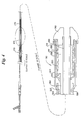
Figure 1a shows a schematic longitudinal cross-sectional view of a medical device delivery system. -
Figure 1b shows a partial exploded view of circled region 1b inFig. 1a . -
Figure 2 shows the distal end of the medical device delivery system ofFig. 1 with the rolling retractable sheath in a retracted position. -
Figure 3 shows a schematic longitudinal cross-sectional view of the distal end of medical device delivery system. -
Figure 4 shows a schematic longitudinal cross-sectional view of the distal end of medical device delivery system. -
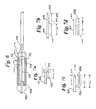
Figures 5a and 5b show schematics of rolling retractable sheaths for use in the present invention. -
Figure 6 shows a schematic longitudinal cross-sectional view of the distal end of medical device delivery system. -
Figures 7a and 7b are schematic longitudinal cross-sectional views of a double walled sheath before and after retraction. -
Figures 7c and 7d are schematic longitudinal cross-sectional views of a sealed double walled sheath before and after retraction. -
Figure 8 shows a suitable stent for use with the inventive medical device delivery system. -
Figure 9 shows a suitable graft for use with the inventive medical device delivery system. -
Figure 10 shows a suitable vena cava filter for use with the inventive medical device delivery system. -
Figure 11 shows a schematic longitudinal cross-section view of the distal end of the present inventive medical device delivery system. - While this invention may be embodied in many different forms, there are described in detail herein specific preferred embodiments of the invention. This description is an exemplification of the principles of the invention as claimed and is not intended to limit the invention to the particular embodiments illustrated.
- Referring to the figures,
Fig. 1a shows a medical device delivery system in general at 110. At the distal end ofinner tube 114 is a medicaldevice mounting region 118.Inner tube 114 is desirably made of flexible, but incompressible construction such as a polymer encapsulated braid or coil. The flexibility of the braid/coil construction allows the medical device delivery system to navigate through body lumens and the incompressibility of the braid/coil aids in maintaining the integrity for the catheter and aids in deployment accuracy when the retractable rolling sheath is being retracted during stent release. The braid/coil may be comprised of stainless steel encased in a polymer such as Polyimide with an inner layer of Teflon™. The inner tube need not, however, be made of incompressible materials. Flexible and compressible materials such as polyethylene may also be used. - Covering medical
device mounting region 118 is a rollingretractable sheath 122 for retaining a medical device on the inner tube. The medical device delivery system further comprises a retraction means for retracting the rolling retractable sheath. - Rolling
retractable sheath 122, disposed concentrically aboutinner tube 114, is formed of a single material folded over on itself. As such, at least a portion of the sheath is double-walled.Inner wall 130 ofsheath 122 is attached toinner tube 114 at aregion 134 proximal to medicaldevice mounting region 118.Outer wall 138 ofsheath 122 is attached toretraction device 126 atregion 142 of the retraction device. A sealedchamber 146 is formed byinner wall 130 andouter wall 138 of the sheath, at least aportion 150 of the inner tube and theportion 154 of the retraction device which is distal to the region ofattachment 142 of the outer wall to the retraction device. The sheath is retractable from a delivery position, as shown inFig. 1a , to a release position as shown inFig. 2 . In the delivery position, the sheath covers at least a portion of the medical device mounting region while in the release position, the sheath no longer covers the medical device mounting region. - A
retraction device 126 is attached to rollingretractable sheath 122.Retraction device 126 comprises apull collar 127 operably attached to a pull-wire 128 which extends to the proximal end of the medical device delivery system. Pullcollar 127 is a ring-shaped member of stainless steel or preferably of a radio-opaque material such as gold affixed to distalouter tube 178 by an appropriate adhesive such as a urethane. The distal outer tube is, in turn, connected to the rolling sheath. The pull wire may be made of suitable material including stainless steel. - The medical device delivery system, optionally, further comprises a collapsible midshaft sheath, as shown in
Fig. 1a and in more detail inFig. 1b . The distal end of proximalouter tube 170 is attached, desirably adhesively bonded, to an accordion-likecollapsible midshaft sheath 174. The distal end ofcollapsible midshaft sheath 174 is, in turn, attached, desirably adhesively bonded, to distalouter tube 178. Pullcollar 127 is attached to the distal end of distalouter tube 178. In operation, the retraction device moves the outer wall in a proximal direction relative to the inner wall so that the sheath no longer covers the medical device mounting region. In so doing,collapsible midshaft sheath 174 decreases in length. Additional information about the collapsible midshaft sheath made be found inUS Patent 5,534,007 to St. Germain and Olson . - Rolling
retractable sheath 122 is retractable from a delivery position as shown inFig. 1 , to a release position as shown inFig. 2 . - As seen in
Fig. 1a , the medical device delivery system further comprises anoptional tip 162 mounted at the distal end ofinner tube 114 abuttingretractable sheath 122Tip 162 may be affixed to the inner tube by an adhesive such as H.B. Fuller 3507, an urethane adhesive, or the like. - Also shown in the embodiment of
Fig. 1a is a self-expandingstent 158 mounted on medical device mounting region 1218 of the system.Stent 158 is contained in medicaldevice containment area 166. - Because sealed
chamber 146 is not in fluid communication with any part of the delivery system proximal of the sheath, the sealed chamber may be coated or filled with a lubricating substance to reduce the friction because the inner and outer walls of the sheath without any direct interaction between the lubricating substance and a bodily fluid. - In another example, as shown in
Fig. 3 , the medical device delivery system shown generally at 210 comprises aninner tube 214 with a medicaldevice mounting region 218 is a rollingretractable sheath 222 for retaining a medical device on the inner tube. Attached to rollingretractable sheath 222 is aretraction device 226 for retracting the sheath. - As in the previous embodiment, rolling
retractable sheath 222, is formed of a single material folded over on itself.Inner wall 230 ofsheath 222 is attached toinner tube 214 at aregion 234 proximal to medicaldevice mounting region 218.Outer wall 238 ofsheath 222 is attached toretraction device 226 atregion 242 of the retraction device. As before,retraction device 226 includes proximalouter tube 270 attached toretractable sheath 274 which in turn is attached to distalouter tube 278. Pull collar 227 is attached to the distal end of the distalouter tube 278 and pull wire 228 extends proximally from pull collar 227. - Also shown in the embodiment of
Fig. 3 is an optional self-expandingstent 258 mounted on medicaldevice mounting region 218 of the system.Stent 258 is contained in medicaldevice containment area 266. - Although
sheath 274 in the unretracted position, as shown inFig. 3 , is shown as being double walled over the entire length ofstent 258, the double walled region of the sheath need not extend over the entire length of the stent but may extend over only a fraction of the stent. Using a sheath whose doubled over region in the unretracted position is of reduced length may prove advantageous in that the overall length of the sheath in the retracted position is also reduced thereby resulting in a delivery system with a smaller profile over a greater length. It is desirable for the double over region to extend over at least one-half of the stent and more desirable to extend over at least one quarter or one eighth of the stent. - Optionally, the
chamber 246 formed byinner wall 230 andouter wall 238 of the sheath and at least a portion of theinner tube 250 and a portion of theretraction device 226 may be sealed. - As seen in
Fig. 3 , the medical device delivery system further comprises anoptional tip 262 mounted at the distal end ofinner tube 214 abuttingretractable sheath 222. - In the example shown in
Fig. 3 , the rollingsheath 222 is made, at least in part, of a porous material capable of allowing fluid therethrough. Suitable porous materials include expanded polytetrafluoroethylene (ePTFE) and polyester. Desirably, the materials will have a pore size ranging from 0.01 mm to 5.0 mm. - The porosity of the inner and outer walls allows medical
device containment area 266 to be flushed free of air by fluid traveling through the inner and outer walls and into the medical device containment area. - In yet another example, as shown in
Figure 4 , the medical device delivery system, shown generally at 310, is constructed similarly to the embodiment ofFig. 2 , differing in that rollingsheath 322 has aninner wall 330 and anouter wall 338, the inner wall formed of at least a first material, and the outer wall formed of at least a second material different from the first material. The delivery system ofFig. 4 further differs from the delivery system ofFig. 3 in thatinner tube 318 is comprised of part of a dual lumen tube. Theother lumen 382 of the dual lumen tube provides for a flush lumen in fluid communication withstent chamber 386. - As before,
retraction device 326 includes proximalouter tube 370 attached toretractable sheath 374 which in turn is attached to distalouter tube 378. Pullcollar 327 is attached to the distal end of the distalouter tube 378 and pullwire 328 extends proximally frompull collar 327. - As seen in
Fig. 4 , the medical device delivery system further comprises anoptional tip 362 mounted at the distal end of inner tube 314 abuttingretractable sheath 322. - Also shown in the example of
Fig. 3 is a self-expandingstent 358 mounted on medicaldevice mounting region 318 of the system.Stent 358 is contained in medicaldevice containment area 366.Optional bumper 372 is also shown.Bumper 372 may be of polyethylene and is affixed to the inner tube by an adhesive such as H.B. Fuller 3507. - Additionally, the medical device delivery system may comprise marker bands (not shown) included to aid in positioning and maybe affixed to the inner tube by adhesive such as Loctite 4011.
-
Inner wall 330 andouter wall 338 may be adhesively bonded together, heat welded, sutured or otherwise mechanically joined together. Suitable adhesives include urethane and epoxy. - While the invention contemplates a wide variety of choices for first and second materials, the materials must be chosen such that the material of the inner wall will have a greater tendency to rollingly move upon the application of a rolling force than the outer wall. For the purposes of this application, the relative tendency of materials to rollingly move may be tested by taking a strip of a given material, immobilizing one end of the strip, folding a small portion of the opposite end of the material over on itself and measuring the force in the longitudinal direction necessary to initiate rolling motion of the folded over end of the material.
- Desirably, a first material that rolls on retraction of the sheath will be selected along with a second material that does not roll on retraction. Desirably, the second material will have a higher hoop strength than the first material. Also, desirably, the outer wall of the sheath in the unretracted position has a higher tensile strength than the inner wall of the sheath. In a preferred embodiment, the outer material is made of high density polyethylene (HDPE) and the inner material is made of poly(block-amide-block-ether) ester materials such as PEBAX™ brand polymers manufactured by Atochem North America, Inc. (Philadelphia PA).
- The materials may also be chosen so that the outer layer is resistant to creep in the radial direction and/or resistant to compression or expansion in the longitudinal direction while the inner layer is flexible, both radially and longitudinally. The extra strength of the outer layer prevents the sheath from creeping under the force of a self-expanding stent contained by the sheath and helps to ensure that the stent will not deploy until the system is actuated. At the same time, the flexibility of the inner layer allows the sheath to be rolled in on itself.
- The materials may also be chosen such that the outer layer is made of a material of higher tensile strength, flexural modulus and/or higher hoop strength than the inner layer. The materials may also be chosen such that the outer layer has a higher degree of longitudinal stiffness than the inner layer.
- In another embodiment of the invention, the rolling retractable sheath is characterized by the presence of an outer wall of a first thickness and an inner wall of a second thickness. The first thickness may be greater or less than the second thickness. Where the outer wall is thinner than the inner wall, the material of the outer wall must have a flexural modulus and/or tensile strength and/or hoop strength and/or longitudinal stiffness in excess of that of the inner material so that the relative thicknesses of the layers is offset by the relative material properties of the walls.
- The invention also contemplates a medical device delivery system having a rolling retractable sheath where the inner wall of the retractable sheath is flexible enough to roll while the outer wall of the retractable sheath is stiff enough to prevent unwanted movement of the stent and the outer and inner walls are made of the same material. The property differentiation results from the inner wall being thinner than the outer wall. This may be accomplished, for example, by providing a tapered tube folded over on itself.
- The invention also contemplates the use of porous materials for the first and/or second materials. Where both materials are porous, the medical device delivery system will be self-priming. Suitable porous materials for use in this embodiment include PTFE, polyester and silicone.
- In a more general way, the invention contemplates the use of thermoplastic elastomers such as polyurethane, polyethylene, polyester, polyvinyl chloride, nylon and their block copolymers as well as PEBAX™ polymers for the double walled sheath. Other suitable materials include fluoropolymers, non-compliant polyethylene terephthalate (PET), polyamide and polyolefin copolymers such as SURLYN™.
- Typically, the materials for use in the double walled sheaths of the invention will exhibit high strength even for wall thicknesses as small as 2.54/1000's of an cm (1/1000's of an inch). Suitable materials include uniaxially oriented films such as are formed by blow molding.
- In order to reduce friction between the outer and inner walls, a suitable lubricant, as is known in the art, may be selectively applied to at least a portion of the inner and/or outer walls. The invention also contemplates completely covering the inner and outer walls with a lubricant. Suitable lubricants include silicones, polyvinyl pyrrolidone, and PPO (polypropylene oxide). Additionally, BioSlide™ coating produced by SciMed made be used as well. BioSlide™ is a hydrophilic, lubricious coating comprising polyethylene oxide and neopentyl glycol diacrylate polymerized in a solution of water and isopropyl alcohol in the presence of a photoinitiator such as azobisisobutronitrile. Other hydrogels such as PEG (polyethylene glycol), PEO/PPO/PEO-polyethylene oxide/polypropylene oxide/polyethylene oxide triblock polymer manufactured by ASF or PPO/PEO/PPO may also be used. Fluids, desirably bio-compatible, may also be used as lubricants in the practice of the invention. The presence of a fluid between the inner and outer walls of the sheath prevents the inner and outer walls from contacting one another thereby reducing the friction between the walls.
- Friction between the inner and outer walls may also be reduced by altering the design of the rolling sheath. The rolling sheath shown in the above figures is reproduced in
Fig. 5a .Inner wall 430 andouter wall 438 are substantially parallel to one another. Other, lower friction geometries are also contemplated such as that shown at 422 inFig. 5b .Inner wall 430 is disposed at an oblique angle relative toouter wall 438 such that the distance between the inner wall and the outer wall increases with the distance from thefold 423 in the rolling sheath. The increased separation between the walls reduces the contact between the walls and hence the frictional interactions between the walls. - Although the use of a flush lumen has only been shown in the example of
Fig. 4 , it is understood that a flush lumen may suitably be used in any of the other embodiments disclosed herein. - Additional details of the design of embodiments of the inventive medical device delivery system which employ collapsible midshaft sheaths, in particular the portion of the device proximal to the rolling retractable sheath, may be found in the various embodiments disclosed in
US 5,534,007 to St. Germain and Olson . - In addition to the use of a collapsible midshaft sheath retraction device for retracting the outer sheath, the invention also contemplates the use of other suitable retraction means as are known in the art including slidably sealed retractable sheaths and midshaft seals as described in
US Patent 5772669 , andUS Patent 5957930 . Other contemplated retraction means include sheaths activated directly by pull-collars as described inUS Patent 5957930 ; and screw-like retraction devices as described inUS Patent 5,201,757 to Heyn et al. all. - Alternatively, the rolling retractable sheath may be a full length sheath which extends to the proximal end of the medical device delivery system.
- In yet another example, as shown generally in
Fig. 6 , the medical device delivery system comprises a rollingretractable sheath 522 closed on itself. The delivery system comprises aninner tube 514 having a medicaldevice mounting region 518 at the distal region for concentrically mounting a medical device thereon. The proximal end of rollingretractable sheath 522 is secured to the inner tube viaoptional bumper 572 at alocation 523 proximal to medicaldevice mounting region 518. Ifoptional bumper 572 is not present, rollingretractable sheath 522 may be secured directly to the inner tube. Rollingretractable sheath 522 containsstent 558 which is mounted over or arounddistal end 518 ofinner tube 514. Depending on the type of stent used, the stent may alternatively be mounted directly on the inner tube. The distal end of rollingretractable sheath 522 is attached to aretraction device 526. Adhesives such as polyurethane, epoxy, cyanoacrylates and acrylics or other suitable means of attachment including heat welding, suturing or other forms of mechanically joining may be used to affix the rolling sheath to the retraction device. As shown inFig. 6 ,retraction device 526 is an outer sheath which covers the rolling sheath and extends in a proximal direction. Rollingretractable sheath 522 may be retracted by pullingouter sheath 526 in a proximal direction. - Rolling
retractable sheath 522 may optionally be provided with longitudinally oriented ribs to provide resistance to buckling. Similarly, a tapered sheath design similar to that shown inFig. 5b and closed on itself at both ends may also be used in order to prevent buckling of the sheath upon retraction of the sheath. -
Outer sheath 526 may be a full length sheath which extends all the way to the proximal end of the medical device delivery system or alternatively may extend proximally for only a portion of the delivery system. In the latter case,outer sheath 526 may be used in conjunction with a collapsible midshaft sheath as disclosed above. - The outer sheath may be made of a homogeneous polymer or a composite. Suitable materials include polyolefin copolymers, Pebax™, polyurethane, nylon, polyethylene, polyesters and other thermoplastic elastomers. It is desirable for the outer sheath to be flexible, but radially non-compliant. Optionally, the outer sheath may be formed of a polymer encapsulated braid or coil. The braid/coil may be formed of stainless steel encased in a polymer such as Polyimide with an inner layer of Teflon™. Where the outer sheath is made of a polymeric tube, slits may be made in the tube to increase the flexibility of the tube without sacrificing radial strength. The outer sheath may be made from a material which is chosen so as to provide support for the rolling sheath as it is retracted, to prevent distention of the rolling sheath.
- Another suitable retraction device is a collar and pull wire. A pull collar, as disclosed above, may be affixed to the distal end of the rolling retractable sheath. A pull wire extending proximally from the pull collar may then be used to retract the rolling sheath. The pull wire may enter the inner tube at a point proximal to the stent and preferably at a point which is at a distance of at least one rolling retractable sheath proximal to the stent so as not interfere with the operation of the rolling sheath.
- As discussed above, in conjunction with several of the other embodiments, the rolling sheath may be formed of one material or may be formed of several materials joined together. Because, however, both the inner and outer walls of the rolling sheath roll in this embodiment, it is desirable that both the outer and inner walls be made of the same materials.
- As in the other embodiments of the invention, lubricants may be used in the interior of the rolling retractable sheath in the embodiment of
Fig. 6 to reduce the frictional interactions between the walls of the sheath and to facilitate rolling. Any of the above lubricants may be employed. - A further advantage of the medical device delivery system shown in
Fig. 6 is the reduced length of the rolling sheath upon retraction as compared with rolling sheaths that are not closed on themselves as in the previous embodiments. Whereas the length of a rolling sheath closed on itself is unchanged upon retraction of the sheath, standard rolling sheaths may double in length upon retraction as the sheath is fully extended and ceases to form a double layer. The reduced length of the fully retracted rolling sheath which is closed on itself as compared with a standard rolling sheath allows for a medical device delivery system of lower profile over a greater portion of the distal end of the system. - As shown in
Figs. 7a-d , the example is directed to medical device delivery systems comprising aninner tube 614 with a medicaldevice mounting region 618 at the distal region for concentrically mounting amedical device 658 thereon, a rollingretractable sheath 622 for retainingmedical device 658 on medicaldevice mounting region 618 and a retraction device (not shown) for retracting the rolling sheath. As further shown inFigs. 7a-d , medicaldevice mounting region 618 is characterized by a medical device mounting length, Lm. Rollingretractable sheath 622 is disposed aboutinner tube 614 with the proximal end of rollingsheath 622 secured toinner tube 614 proximal of the medicaldevice mounting region 618.Rolling sheath 622 in an unretracted state, as shown inFigs. 7a and 7c , is characterized by a first length, L1, as defined by the distance between the proximal-most point on the unretracted sheath and the distal-most point on the unretracted sheath.Rolling sheath 622 in the unretracted state is further characterized by a double wall length Ld as measured by the length over which the sheath forms a double wall.Rolling sheath 622 upon retraction, as shown inFigs. 7b and 7d , is characterized by a second length, L2, as defined by the distance between the proximal-most point on the retracted sheath and the distal-most point on the retracted sheath. Finally, rollingsheath 622 is operably connected to a retraction device (not shown) for retraction of the rolling sheath. - The delivery system is further characterized in that the difference between the second length L2 and the first length L1 is less than the medical device mounting length Lm. Desirably the difference between the second length L2 and the first length L1 will be less than half of the medical device mounting length. More desirably, the difference between the second length L2 and the first length L1 will be substantially equal to zero as in
Figs. 7c and 7d where the rolling sheath is closed on itself or where the sheath has a very short double walled region Ld as inFigs. 7a and 7b . It is also desirable for the second length L2 to be less than twice the first length L1 and/or less than twice the medical device mounting length Lm. - Although in a preferred embodiment, the above-disclosed inventive medical devices are used for delivery of self-expanding stents such as that shown in
Fig. 8 at 758, other stents may also be used in conjunction with this invention including mechanically expandable stents such as balloon expandable stents. A balloon is provided in the medical device mounting region of the delivery device and a stent mounted thereon. Suitable inflation means as are known in the art, such as an inflation lumen, are provided. Other suitable medical device for use with the present invention include grafts or stents/grafts, including that shown inFig. 9 at 858 and vena cava filters, including that shown inFig. 10 at 958. - While the medical devices have been described above as being concentrically mounted about the medical device mounting region of the inner tube, the invention is not intended to be so limited. The invention is directly more generally at a medical device delivery system with a medical device mounted about the medical device receiving region, whether or not the medical device is concentric with the inner tube. Moreover, the term 'mounted' as used in the context of the medical device being mounted on the medical device receiving region is intended to include the case where the medical device is in contact with the medical device receiving region of the inner tube as well as the case where the medical device surrounds at least a portion of the medical device mounting region although it is not actually in contact with said region of the inner tube. An example of the former is as a stent crimped onto the inner tube while an example of the latter is a self expanding stent which is maintained in place about the inner tube by a sheath.
- Further, although the rolling retractable sheath has been referred to as being disposed concentrically about the inner tube, the invention further contemplates the possibility of the rolling retractable sheath being disposed non-concentrically about the inner tube.
- The present example is also directed to methods of delivering a medical device, such as those described above, to a desired bodily location using any of the devices described herein. One such method comprises the steps of providing one of the above-described medical device delivery systems and a medical device and mounting the medical device on the medical device mounting region of the system. The medical device delivery system is then percutaneously inserted in a bodily lumen containing a bodily fluid. Where the sheath is made of a porous material, bodily fluids may pass through the sheath so as to self-prime the medical device delivery system. The medical device is traversed through the bodily lumen until the desired bodily location is reached at which point the rolling retractable sheath is retracted proximally so as to expose the medical device. The medical device delivery system is then withdrawn from the bodily lumen.
- In particular, this method may be used to deliver a self-expanding stent to a desired bodily location. Upon retraction of the sheath, the stent self-expands and the delivery system is then withdrawn.
Figure 6 shows one such suitable stent 458 for use with the present invention. Other medical devices such as balloon or mechanically expandable stents may similarly be delivered and deployed. In this case of the balloon expandable stent, the delivery system must be modified to include a balloon mounted over the inner tube and under at least a portion of the stent and to further include suitable tubes to allow for inflation of the balloon, as is well known in the art. Other medical devices that may be delivered by using the above method include grafts and vena cava filters. - The embodiment shown in
Fig. 11 is substantially similar to the embodiment shown inFig 1a . As previously stated aretraction device 126 is attached to rollingretractable sheath 122.Retraction device 126 comprises apull collar 127 operably attached to a pull-wire 128 which extends to the proximal end of the medical device delivery system. Pullcollar 127 is affixed to distalouter tube 178. The distal outer tube is, in turn, connected to the rolling sheath. The pull wire may be made of suitable material including stainless steel. - In the embodiment shown in
Fig. 11 however,chamber 146 is not sealed by the presence ofpull collar 127 between theouter tube 128 andinner tube 114. In thepresent embodiment chamber 146 is in fluid communication withinflation lumen 200. By inflatingchamber 146 with a fluid supplied throughlumen 200, thesheath 122 may be utilized as a dilation balloon. - In order to effectively utilize the
sheath 122 as a dilation balloon prior to stent delivery, the sheath must be prevented from retraction off of thestent 158 during inflation ofchamber 146. During inflation of thesheath 122,retraction device 126 acts as a stiffening member to hold thesheath 122 in place thereby preventing any proximal movement or retraction of thesheath 122. Thesheath 122 may be inflated prior to stent delivery in order to clear protrusions of plaque or other stenosis. - After the sheath has been inflated, the
chamber 146 may be evacuated of fluid via theinflation lumen 200 and theretraction device 126 drawn proximally in order to pull back the sheath of thestent 158. Alternatively, theretraction device 126 may be relaxed to allow the presence of the fluid withinchamber 146 to draw back the sheath in the manner previously described above. - To prevent distortion of the
stent 158 which may potentially result from inflation of thesheath 122, the sheath is preferably constructed so that theouter wall 138 of the sheath is be composed of a higher compliance material than theinner wall 130. In addition,inner wall 130 may be positioned immediately adjacent tostent 158 with no space provided therebetween. - When the
sheath 122 is used as a dilation balloon the sheath must be at least partially composed of a suitable balloon or expandable material. Preferably,sheath 122 is at least partially composed of polyethylene or polyolefin copolymers such as SURLYN™. - While several specific embodiments of the present invention as claimed have been described, the invention is directed more generally toward the use of rolling membranes in the manner described above in any other suitable catheter design not specifically described herein including over-the-wire, fixed-wire and rapid-exchange catheters.
- In an over-the-wire embodiment, the inner tube extends proximally to a manifold and a guide wire may be inserted into the inner tube from the proximal end, the guide wire extending to the distal end of the system. The medical device delivery system may then ride on the guidewire.
- In the case of the fixed-wire design, the guidewire is fixedly attached to the medical device delivery system. A fixed-wire delivery system is described in
U.S. 5,702,364 to Euteneuer et al. , and may be suitably modified for use with the inventive medical device delivery system. - Similarly, a rapid exchange delivery system is described in
U.S. 5,534,007 to St. Germain et al. , and may be suitably modified for use with the inventive medical device delivery system. Specifically, the rapid-exchange version may be realized by having the inner tube terminate in a guide wire port in a location along the system distal to the proximal end of the system to allow for insertion of a guide wire therein. In the rapid-exchange embodiment, only a portion of the medical device delivery system rides on a guidewire. Typically, the usable length of the medical device delivery system is approximately 135 cm. For a rapid-exchange medical device delivery system, the distance from where the guide wire accesses the inner tube to the distal tip will be approximately 5 cm to 45 cm. - In addition to being directed to the embodiments described above and claimed below, the present invention is further directed to embodiments having different combinations of the features as claimed below. As such, the invention is also directed to other embodiments having any other possible combination of the dependent features claimed below.
- The above examples and disclosure are intended to be illustrative and not exhaustive. These examples and description will suggest many variations and alternatives to one of ordinary skill in this art. All these alternatives and variations are intended to be included within the scope of the attached claims. Those familiar with the art may recognize other equivalents to the specific embodiments described herein which equivalents are also intended to be encompassed by the claims attached hereto.
Claims (16)
- A medical device delivery system (110) comprising:• an inner tube (114), having a distal region and a proximal region, the inner tube (114) having a medical device mounting region (118) at the distal region for mounting a medical device thereon;• an outer tube (178), at least partially disposed about the inner tube;• a rolling retractable sheath (122) for retaining a medical device about the inner tube and for dilatation of a body vessel, the sheath having a proximal end and a distal end, the sheath disposed about the inner tube, the sheath having an uninflated state and an inflated dilatation state, the sheath (122) further having an inner wall (130) attached to the inner tube (114) proximal to the medical device mounting region and an outer wall, the inner wall extending distally and attached to the outer wall, the outer wall extending proximally and attached to the outer tube, the sheath defining a chamber (146), characterized in that the chamber (146) is in fluid communication with an inflation lumen (200).
- The medical device delivery system of claim 1, wherein the outer tube (178) further comprises a retraction device (126), the retraction device (126) retaining the rolling retractable sheath (122) in the delivery position when the rolling retractable sheath (122) is in the inflated state, the retraction device moving the outer wall in a proximal direction relative to the inner wall to expose the medical device mounting region, the retraction device operably connected to the outer wall (138) of the rolling retractable sheath (122).
- The medical delivery device (110) of claim 2, wherein the retraction device (126) further comprises a catheter having proximal and distal ends and a lumen therein for receiving the inner tube (114) therein, the distal end of the inner tube extending (114) beyond the distal end of the catheter, the outer wall of the rolling retractable sheath (122) attached to the distal end of the catheter.
- The medical device delivery system of claim 1, wherein the inner and outer walls (130, 138) are adhesively bonded together at an end of the rolling double walled member.
- The medical device delivery system of claim 1, wherein the inner and outer walls are mechanically joined together at an end of the rolling double walled member.
- The medical device delivery system of claim 1, wherein the inner wall (130) of the rolling retractable sheath (122) is formed of at least a first material and the outer wall (138) is formed of at least a second material different from the first material.
- The medical device delivery system of claim 1, wherein the inner wall (130) has a lower compliance than the outer wall (138).
- The medical device delivery system of claim 1, wherein the outer wall (138) of the sheath is thinner than the inner wall (130) of the sheath.
- The medical device delivery system of claim 1, wherein the inner and outer walls (130, 138) of the sheath are obliquely disposed relative to each other.
- The medical device delivery system of claim 1 further comprising a lubricant applied to at least a portion of one or more of the inner and outer walls so as to reduce friction between the inner and outer walls.
- The medical device delivery system of claim 1 further comprising a medical device selected from the group consisting of stents, grafts and vena cava filters, the medical device mounted on the medical device mounting region of the inner tube.
- The medical device delivery system of claim 1 wherein the medical device is a stent and the stent is self-expandable.
- The medical device delivery system of claim 1 configured for use a in a mode selected from the group consisting of fixed-wire mode, over-the-wire mode and rapid-exchange mode.
- The medical device delivery system of claim 2, the retraction device further comprising a pull wire.
- The medical device delivery system of claim 2, the retraction device further comprising an outer sheath.
- The medical device delivery system of claim 1, wherein the inner wall and the outer wall are integrally formed.
Applications Claiming Priority (3)
| Application Number | Priority Date | Filing Date | Title |
|---|---|---|---|
| US09/711,687 US6544278B1 (en) | 1998-11-06 | 2000-11-10 | Rolling membrane stent delivery system |
| US711687 | 2000-11-10 | ||
| PCT/US2001/046725 WO2002038084A2 (en) | 2000-11-10 | 2001-11-09 | Improved rolling membrane stent delivery system |
Publications (2)
| Publication Number | Publication Date |
|---|---|
| EP1333778A2 EP1333778A2 (en) | 2003-08-13 |
| EP1333778B1 true EP1333778B1 (en) | 2008-04-09 |
Family
ID=24859102
Family Applications (1)
| Application Number | Title | Priority Date | Filing Date |
|---|---|---|---|
| EP01990855A Expired - Lifetime EP1333778B1 (en) | 2000-11-10 | 2001-11-09 | Improved rolling membrane stent delivery system |
Country Status (9)
| Country | Link |
|---|---|
| US (4) | US6544278B1 (en) |
| EP (1) | EP1333778B1 (en) |
| JP (1) | JP2004531289A (en) |
| AT (1) | ATE391471T1 (en) |
| AU (1) | AU2002230620A1 (en) |
| CA (1) | CA2436193C (en) |
| DE (1) | DE60133572T2 (en) |
| ES (1) | ES2301572T3 (en) |
| WO (1) | WO2002038084A2 (en) |
Cited By (2)
| Publication number | Priority date | Publication date | Assignee | Title |
|---|---|---|---|---|
| CN1972636B (en) * | 2004-04-22 | 2010-09-01 | 安乔斯里德公司 | Catheter |
| US9439662B2 (en) | 2005-07-05 | 2016-09-13 | Angioslide Ltd. | Balloon catheter |
Families Citing this family (209)
| Publication number | Priority date | Publication date | Assignee | Title |
|---|---|---|---|---|
| US20100030256A1 (en) * | 1997-11-12 | 2010-02-04 | Genesis Technologies Llc | Medical Devices and Methods |
| US9498604B2 (en) * | 1997-11-12 | 2016-11-22 | Genesis Technologies Llc | Medical device and method |
| US6740113B2 (en) * | 1998-05-29 | 2004-05-25 | Scimed Life Systems, Inc. | Balloon expandable stent with a self-expanding portion |
| US6544278B1 (en) * | 1998-11-06 | 2003-04-08 | Scimed Life Systems, Inc. | Rolling membrane stent delivery system |
| US7018401B1 (en) | 1999-02-01 | 2006-03-28 | Board Of Regents, The University Of Texas System | Woven intravascular devices and methods for making the same and apparatus for delivery of the same |
| US8034100B2 (en) | 1999-03-11 | 2011-10-11 | Endologix, Inc. | Graft deployment system |
| US6261316B1 (en) | 1999-03-11 | 2001-07-17 | Endologix, Inc. | Single puncture bifurcation graft deployment system |
| US6660031B2 (en) | 2001-04-11 | 2003-12-09 | Scimed Life Systems, Inc. | Multi-length delivery system |
| GB0120645D0 (en) | 2001-08-24 | 2001-10-17 | Smiths Group Plc | Medico-surgical devices |
| US7153320B2 (en) * | 2001-12-13 | 2006-12-26 | Scimed Life Systems, Inc. | Hydraulic controlled retractable tip filter retrieval catheter |
| US6932829B2 (en) * | 2002-06-24 | 2005-08-23 | Cordis Corporation | Centering catheter |
| US7625337B2 (en) | 2003-01-17 | 2009-12-01 | Gore Enterprise Holdings, Inc. | Catheter assembly |
| US7198636B2 (en) * | 2003-01-17 | 2007-04-03 | Gore Enterprise Holdings, Inc. | Deployment system for an endoluminal device |
| US9433745B2 (en) * | 2003-01-17 | 2016-09-06 | W.L. Gore & Associates, Inc. | Puncturing tool for puncturing catheter shafts |
| US8016752B2 (en) * | 2003-01-17 | 2011-09-13 | Gore Enterprise Holdings, Inc. | Puncturable catheter |
| US7753945B2 (en) * | 2003-01-17 | 2010-07-13 | Gore Enterprise Holdings, Inc. | Deployment system for an endoluminal device |
| US20060058866A1 (en) * | 2003-01-17 | 2006-03-16 | Cully Edward H | Deployment system for an expandable device |
| GB0307350D0 (en) | 2003-03-29 | 2003-05-07 | Smiths Group Plc | Catheters |
| DE10346200A1 (en) * | 2003-09-30 | 2005-05-04 | Jotec Gmbh | Delivery system with a self-expanding stent |
| US7208008B2 (en) * | 2003-10-02 | 2007-04-24 | Medtronic Vascular, Inc. | Balloonless direct stenting device |
| US20050085826A1 (en) * | 2003-10-21 | 2005-04-21 | Scimed Life Systems, Inc. | Unfolding balloon catheter for proximal embolus protection |
| US20050125050A1 (en) * | 2003-12-04 | 2005-06-09 | Wilson Cook Medical Incorporated | Biliary stent introducer system |
| US7225518B2 (en) * | 2004-02-23 | 2007-06-05 | Boston Scientific Scimed, Inc. | Apparatus for crimping a stent assembly |
| JP4249064B2 (en) * | 2004-03-10 | 2009-04-02 | オリンパス株式会社 | Endoscope |
| WO2005094283A2 (en) | 2004-03-25 | 2005-10-13 | Hauser David L | Vascular filter device |
| WO2005096994A1 (en) * | 2004-03-31 | 2005-10-20 | Wilson-Cook Medical Inc. | Stent introducer system |
| US20160022293A1 (en) * | 2004-04-15 | 2016-01-28 | Genesis Technologies Llc | Medical device and method |
| US7285130B2 (en) * | 2004-04-27 | 2007-10-23 | Boston Scientific Scimed, Inc. | Stent delivery system |
| US7799050B2 (en) * | 2004-05-05 | 2010-09-21 | Boston Scientific Scimed, Inc. | Devices and methods for magnetically manipulating intravascular devices |
| US8308789B2 (en) * | 2004-07-16 | 2012-11-13 | W. L. Gore & Associates, Inc. | Deployment system for intraluminal devices |
| ATE390096T1 (en) * | 2004-07-28 | 2008-04-15 | Cordis Corp | INTRODUCER DEVICE WITH A LOW EXPANSION FORCE |
| US7955370B2 (en) * | 2004-08-06 | 2011-06-07 | Boston Scientific Scimed, Inc. | Stent delivery system |
| US20060036308A1 (en) * | 2004-08-12 | 2006-02-16 | Medtronic Vascular, Inc. | Stent with extruded covering |
| US7393358B2 (en) * | 2004-08-17 | 2008-07-01 | Boston Scientific Scimed, Inc. | Stent delivery system |
| JP4494144B2 (en) * | 2004-09-16 | 2010-06-30 | Junken Medical株式会社 | Tubular organ treatment tool |
| EP1793765B1 (en) * | 2004-09-28 | 2011-03-16 | Cordis Corporation | Thin film medical device and delivery system |
| WO2006042114A1 (en) | 2004-10-06 | 2006-04-20 | Cook, Inc. | Emboli capturing device having a coil and method for capturing emboli |
| US9339403B2 (en) * | 2004-11-12 | 2016-05-17 | Icon Medical Corp. | Medical adhesive for medical devices |
| DE102005003632A1 (en) | 2005-01-20 | 2006-08-17 | Fraunhofer-Gesellschaft zur Förderung der angewandten Forschung e.V. | Catheter for the transvascular implantation of heart valve prostheses |
| US7918880B2 (en) | 2005-02-16 | 2011-04-05 | Boston Scientific Scimed, Inc. | Self-expanding stent and delivery system |
| US7632296B2 (en) | 2005-03-03 | 2009-12-15 | Boston Scientific Scimed, Inc. | Rolling membrane with hydraulic recapture means for self expanding stent |
| US8221446B2 (en) | 2005-03-15 | 2012-07-17 | Cook Medical Technologies | Embolic protection device |
| US8945169B2 (en) | 2005-03-15 | 2015-02-03 | Cook Medical Technologies Llc | Embolic protection device |
| ES2764992T3 (en) * | 2005-04-04 | 2020-06-05 | Flexible Stenting Solutions Inc | Flexible stent |
| US8435279B2 (en) * | 2005-06-14 | 2013-05-07 | Advanced Cardiovascular Systems, Inc. | Delivery system for a device such as a stent |
| US8556851B2 (en) | 2005-07-05 | 2013-10-15 | Angioslide Ltd. | Balloon catheter |
| US8038704B2 (en) * | 2005-07-27 | 2011-10-18 | Paul S. Sherburne | Stent and other objects removal from a body |
| US8187298B2 (en) | 2005-08-04 | 2012-05-29 | Cook Medical Technologies Llc | Embolic protection device having inflatable frame |
| US7778684B2 (en) * | 2005-08-08 | 2010-08-17 | Boston Scientific Scimed, Inc. | MRI resonator system with stent implant |
| US8377092B2 (en) * | 2005-09-16 | 2013-02-19 | Cook Medical Technologies Llc | Embolic protection device |
| US8632562B2 (en) | 2005-10-03 | 2014-01-21 | Cook Medical Technologies Llc | Embolic protection device |
| US8182508B2 (en) | 2005-10-04 | 2012-05-22 | Cook Medical Technologies Llc | Embolic protection device |
| US8252017B2 (en) | 2005-10-18 | 2012-08-28 | Cook Medical Technologies Llc | Invertible filter for embolic protection |
| US8216269B2 (en) * | 2005-11-02 | 2012-07-10 | Cook Medical Technologies Llc | Embolic protection device having reduced profile |
| US8152831B2 (en) | 2005-11-17 | 2012-04-10 | Cook Medical Technologies Llc | Foam embolic protection device |
| US20070213813A1 (en) | 2005-12-22 | 2007-09-13 | Symetis Sa | Stent-valves for valve replacement and associated methods and systems for surgery |
| US11026822B2 (en) | 2006-01-13 | 2021-06-08 | C. R. Bard, Inc. | Stent delivery system |
| US9375215B2 (en) * | 2006-01-20 | 2016-06-28 | W. L. Gore & Associates, Inc. | Device for rapid repair of body conduits |
| US20070208350A1 (en) * | 2006-03-06 | 2007-09-06 | Gunderson Richard C | Implantable medical endoprosthesis delivery systems |
| US20070239256A1 (en) * | 2006-03-22 | 2007-10-11 | Jan Weber | Medical devices having electrical circuits with multilayer regions |
| GB0615658D0 (en) | 2006-08-07 | 2006-09-13 | Angiomed Ag | Hand-held actuator device |
| US20080071307A1 (en) | 2006-09-19 | 2008-03-20 | Cook Incorporated | Apparatus and methods for in situ embolic protection |
| CA2934168C (en) | 2006-10-22 | 2019-04-02 | Idev Technologies, Inc. | Devices and methods for stent advancement |
| US8177798B2 (en) * | 2006-12-05 | 2012-05-15 | Tyco Healthcare Group Lp | Adhesive coated stent and insertion instrument |
| US8523931B2 (en) * | 2007-01-12 | 2013-09-03 | Endologix, Inc. | Dual concentric guidewire and methods of bifurcated graft deployment |
| US9901434B2 (en) | 2007-02-27 | 2018-02-27 | Cook Medical Technologies Llc | Embolic protection device including a Z-stent waist band |
| US7896915B2 (en) | 2007-04-13 | 2011-03-01 | Jenavalve Technology, Inc. | Medical device for treating a heart valve insufficiency |
| US8764816B2 (en) * | 2007-05-07 | 2014-07-01 | W. L. Gore & Associates, Inc. | Stent delivery and deployment system |
| GB0713497D0 (en) | 2007-07-11 | 2007-08-22 | Angiomed Ag | Device for catheter sheath retraction |
| US7988723B2 (en) | 2007-08-02 | 2011-08-02 | Flexible Stenting Solutions, Inc. | Flexible stent |
| ES2586121T3 (en) | 2007-08-21 | 2016-10-11 | Symetis Sa | Replacement valve |
| US9138307B2 (en) | 2007-09-14 | 2015-09-22 | Cook Medical Technologies Llc | Expandable device for treatment of a stricture in a body vessel |
| US8419748B2 (en) | 2007-09-14 | 2013-04-16 | Cook Medical Technologies Llc | Helical thrombus removal device |
| US8252018B2 (en) | 2007-09-14 | 2012-08-28 | Cook Medical Technologies Llc | Helical embolic protection device |
| EP2190388B1 (en) | 2007-10-17 | 2014-03-05 | Angiomed GmbH & Co. Medizintechnik KG | Delivery system for a self-expanding device for placement in a bodily lumen |
| WO2009053497A1 (en) * | 2007-10-25 | 2009-04-30 | Symetis Sa | Stents, valved-stents and methods and systems for delivery thereof |
| US8845712B2 (en) * | 2008-01-15 | 2014-09-30 | W. L. Gore & Associates, Inc. | Pleated deployment sheath |
| WO2009105699A1 (en) | 2008-02-22 | 2009-08-27 | Endologix, Inc. | Design and method of placement of a graft or graft system |
| US9044318B2 (en) | 2008-02-26 | 2015-06-02 | Jenavalve Technology Gmbh | Stent for the positioning and anchoring of a valvular prosthesis |
| WO2011104269A1 (en) | 2008-02-26 | 2011-09-01 | Jenavalve Technology Inc. | Stent for the positioning and anchoring of a valvular prosthesis in an implantation site in the heart of a patient |
| US8236040B2 (en) | 2008-04-11 | 2012-08-07 | Endologix, Inc. | Bifurcated graft deployment systems and methods |
| WO2009132045A2 (en) | 2008-04-21 | 2009-10-29 | Nfocus Neuromedical, Inc. | Braid-ball embolic devices and delivery systems |
| GB0815339D0 (en) | 2008-08-21 | 2008-10-01 | Angiomed Ag | Method of loading a stent into a sheath |
| EP2278943B1 (en) | 2008-05-09 | 2014-03-26 | Angiomed GmbH & Co. Medizintechnik KG | Method of loading a stent into a sheath |
| WO2009140437A1 (en) | 2008-05-13 | 2009-11-19 | Nfocus Neuromedical, Inc. | Braid implant delivery systems |
| US8333003B2 (en) | 2008-05-19 | 2012-12-18 | Boston Scientific Scimed, Inc. | Bifurcation stent crimping systems and methods |
| US20090312832A1 (en) * | 2008-06-13 | 2009-12-17 | Cook Incorporated | Slip layer delivery catheter |
| EP2303183A4 (en) * | 2008-06-24 | 2015-11-04 | Bioactive Surgical Inc | Surgical sutures incorporated with stem cells or other bioactive materials |
| EP2520320B1 (en) | 2008-07-01 | 2016-11-02 | Endologix, Inc. | Catheter system |
| JP2011526529A (en) | 2008-07-02 | 2011-10-13 | アンジオスライド リミテッド | Balloon catheter system and method of use thereof |
| EP2341843A1 (en) | 2008-07-22 | 2011-07-13 | Micro Therapeutics, Inc. | Vascular remodeling device |
| US9149376B2 (en) | 2008-10-06 | 2015-10-06 | Cordis Corporation | Reconstrainable stent delivery system |
| US8388644B2 (en) | 2008-12-29 | 2013-03-05 | Cook Medical Technologies Llc | Embolic protection device and method of use |
| GB0823716D0 (en) | 2008-12-31 | 2009-02-04 | Angiomed Ag | Stent delivery device with rolling stent retaining sheath |
| US10045868B2 (en) * | 2009-03-04 | 2018-08-14 | W. L. Gore & Associates Inc. | Atraumatic vascular graft removal sheath |
| US8326437B2 (en) * | 2009-03-04 | 2012-12-04 | W. L. Gore & Associates, Inc. | Atraumatic lead removal sheath |
| US20100249815A1 (en) * | 2009-03-25 | 2010-09-30 | Cook Incorporated | Everted sheath thrombectomy device |
| EP2429452B1 (en) | 2009-04-28 | 2020-01-15 | Endologix, Inc. | Endoluminal prosthesis system |
| US8435282B2 (en) | 2009-07-15 | 2013-05-07 | W. L. Gore & Associates, Inc. | Tube with reverse necking properties |
| US8936634B2 (en) | 2009-07-15 | 2015-01-20 | W. L. Gore & Associates, Inc. | Self constraining radially expandable medical devices |
| US20110034987A1 (en) * | 2009-08-04 | 2011-02-10 | Kennedy Kenneth C | Roll sleeve mechanism for proximal release stent |
| CN107260367B (en) | 2009-11-02 | 2019-11-29 | 西美蒂斯股份公司 | Aorta bioprosthesis and the system delivered for it |
| US20110118817A1 (en) * | 2009-11-17 | 2011-05-19 | Boston Scientific Scimed, Inc. | Stent delivery system |
| GB0921237D0 (en) | 2009-12-03 | 2010-01-20 | Angiomed Ag | Stent device delivery system and method of making such |
| GB0921238D0 (en) | 2009-12-03 | 2010-01-20 | Angiomed Ag | Stent device delivery system and method of making such |
| GB0921236D0 (en) | 2009-12-03 | 2010-01-20 | Angiomed Ag | Stent device delivery system and method of making such |
| GB0921240D0 (en) | 2009-12-03 | 2010-01-20 | Angiomed Ag | Stent device delivery system and method of making such |
| US8016872B2 (en) * | 2009-12-22 | 2011-09-13 | Cook Medical Technologies Llc | Deployment and dilation with an expandable roll sock delivery system |
| WO2011089599A1 (en) | 2010-01-19 | 2011-07-28 | Angioslide Ltd. | Balloon catheter system and methods of making and use thereof |
| WO2011094638A1 (en) | 2010-01-28 | 2011-08-04 | Micro Therapeutics, Inc. | Vascular remodeling device |
| AU2014203064B2 (en) * | 2010-05-05 | 2015-06-11 | Neovasc Tiara Inc. | Transcatheter mitral valve prosthesis |
| US8579964B2 (en) | 2010-05-05 | 2013-11-12 | Neovasc Inc. | Transcatheter mitral valve prosthesis |
| CN103002833B (en) | 2010-05-25 | 2016-05-11 | 耶拿阀门科技公司 | Artificial heart valve and comprise artificial heart valve and support through conduit carry interior prosthese |
| US9561094B2 (en) | 2010-07-23 | 2017-02-07 | Nfinium Vascular Technologies, Llc | Devices and methods for treating venous diseases |
| US9987461B2 (en) * | 2010-10-13 | 2018-06-05 | Cook Medical Technologies Llc | Hemodialysis catheter with thrombus blocker |
| US9931232B2 (en) | 2010-10-21 | 2018-04-03 | Boston Scientific Scimed, Inc. | Stent delivery system |
| GB201017834D0 (en) * | 2010-10-21 | 2010-12-01 | Angiomed Ag | System to deliver a bodily implant |
| EP2564818B1 (en) | 2010-10-29 | 2015-05-13 | Olympus Medical Systems Corp. | Medical stent |
| US10111767B2 (en) | 2010-10-29 | 2018-10-30 | Abbott Cardiovascular Systems Inc. | Sheaths used in polymer scaffold delivery systems |
| US20120109279A1 (en) | 2010-11-02 | 2012-05-03 | Endologix, Inc. | Apparatus and method of placement of a graft or graft system |
| CN103298432B (en) | 2010-11-17 | 2016-03-02 | 波士顿科学西美德公司 | stent delivery system |
| EP2640321B1 (en) | 2010-11-17 | 2017-06-14 | Boston Scientific Scimed, Inc. | Stent delivery systems and locking members for use with stent delivery systems |
| EP2640324B1 (en) | 2010-11-17 | 2015-02-18 | Boston Scientific Scimed, Inc. | Stent delivery system |
| GB201020373D0 (en) | 2010-12-01 | 2011-01-12 | Angiomed Ag | Device to release a self-expanding implant |
| CN103370016B (en) * | 2010-12-15 | 2016-10-19 | 科洛戈德有限公司 | For bypassing the system and method for anastomotic position |
| AU2012214240B2 (en) | 2011-02-11 | 2015-03-12 | Covidien Lp | Two-stage deployment aneurysm embolization devices |
| EP2680915B1 (en) | 2011-03-01 | 2021-12-22 | Endologix LLC | Catheter system |
| US9089332B2 (en) | 2011-03-25 | 2015-07-28 | Covidien Lp | Vascular remodeling device |
| EP2510972B1 (en) * | 2011-04-14 | 2014-08-06 | Biotronik AG | Catheter device |
| US9308087B2 (en) | 2011-04-28 | 2016-04-12 | Neovasc Tiara Inc. | Sequentially deployed transcatheter mitral valve prosthesis |
| EP2701788A1 (en) | 2011-04-29 | 2014-03-05 | Boston Scientific Scimed, Inc. | Protective surfaces for drug-coated medical devices |
| US8414528B2 (en) | 2011-05-27 | 2013-04-09 | Abbott Cardiovascular Systems Inc. | Polymer scaffold sheaths |
| US8852257B2 (en) | 2011-06-21 | 2014-10-07 | Abbott Cardiovascular Systems Inc. | Sheaths used with polymer scaffold |
| US20120330350A1 (en) * | 2011-06-27 | 2012-12-27 | Jones Donald K | Methods and systems for performing thrombectomy procedures |
| US10213329B2 (en) * | 2011-08-12 | 2019-02-26 | W. L. Gore & Associates, Inc. | Evertable sheath devices, systems, and methods |
| US9060886B2 (en) | 2011-09-29 | 2015-06-23 | Covidien Lp | Vascular remodeling device |
| WO2013067168A1 (en) | 2011-11-02 | 2013-05-10 | Boston Scientific Scimed, Inc. | Stent delivery systems and methods for use |
| US10213187B1 (en) | 2012-01-25 | 2019-02-26 | Mubin I. Syed | Method and apparatus for percutaneous superficial temporal artery access for carotid artery stenting |
| US20130274873A1 (en) | 2012-03-22 | 2013-10-17 | Symetis Sa | Transcatheter Stent-Valves and Methods, Systems and Devices for Addressing Para-Valve Leakage |
| US11207176B2 (en) | 2012-03-22 | 2021-12-28 | Boston Scientific Scimed, Inc. | Transcatheter stent-valves and methods, systems and devices for addressing para-valve leakage |
| US20130304180A1 (en) | 2012-05-09 | 2013-11-14 | Michael L. Green | Catheter having dual balloon hydraulic actuator |
| US9011513B2 (en) * | 2012-05-09 | 2015-04-21 | Abbott Cardiovascular Systems Inc. | Catheter having hydraulic actuator |
| US9364358B2 (en) | 2012-07-27 | 2016-06-14 | Medinol Ltd. | Catheter with retractable cover and pressurized fluid |
| US9314248B2 (en) | 2012-11-06 | 2016-04-19 | Covidien Lp | Multi-pivot thrombectomy device |
| US8784434B2 (en) | 2012-11-20 | 2014-07-22 | Inceptus Medical, Inc. | Methods and apparatus for treating embolism |
| BR102013029585B1 (en) | 2012-11-20 | 2021-02-02 | Cook Medical Technologies LLC. | catheter set for applying an endoluminal sleeve and method for preparing a catheter set for delivering an endoluminal sleeve |
| WO2014081947A1 (en) | 2012-11-21 | 2014-05-30 | Syed Mubin I | System for the intravascular placement of a medical device |
| CN105025968A (en) | 2012-12-04 | 2015-11-04 | 安乔斯里德公司 | Balloon catheter and methods of use thereof |
| US9320630B2 (en) | 2012-12-26 | 2016-04-26 | Stryker Corporation | Implant delivery assembly and method of use |
| US9295571B2 (en) | 2013-01-17 | 2016-03-29 | Covidien Lp | Methods and apparatus for luminal stenting |
| US9763819B1 (en) | 2013-03-05 | 2017-09-19 | W. L. Gore & Associates, Inc. | Tapered sleeve |
| US9283101B2 (en) | 2013-03-12 | 2016-03-15 | Abbott Cardiovascular Systems Inc. | Catheter having hydraulic actuator and locking system |
| US10420662B2 (en) | 2013-03-12 | 2019-09-24 | Abbott Cardiovascular Systems Inc. | Catheter having movable tubular structure and proximal stopper |
| US10531971B2 (en) | 2013-03-12 | 2020-01-14 | Abbott Cardiovascular System Inc. | Balloon catheter having hydraulic actuator |
| US9463105B2 (en) | 2013-03-14 | 2016-10-11 | Covidien Lp | Methods and apparatus for luminal stenting |
| CN105142545B (en) | 2013-03-15 | 2018-04-06 | 柯惠有限合伙公司 | Locking device |
| JP6563394B2 (en) | 2013-08-30 | 2019-08-21 | イェーナヴァルヴ テクノロジー インコーポレイテッド | Radially foldable frame for an artificial valve and method for manufacturing the frame |
| WO2015061365A1 (en) | 2013-10-21 | 2015-04-30 | Inceptus Medical, Llc | Methods and apparatus for treating embolism |
| US9907641B2 (en) | 2014-01-10 | 2018-03-06 | W. L. Gore & Associates, Inc. | Implantable intraluminal device |
| US10966850B2 (en) * | 2014-03-06 | 2021-04-06 | W. L. Gore & Associates, Inc. | Implantable medical device constraint and deployment apparatus |
| US9364361B2 (en) | 2014-03-13 | 2016-06-14 | Abbott Cardiovascular Systems Inc. | Striped sheaths for medical devices |
| EP3122293B1 (en) | 2014-03-24 | 2019-04-24 | Boston Scientific Scimed, Inc. | Self-expanding stent delivery system |
| EP3151904A4 (en) | 2014-06-04 | 2018-02-14 | Nfinium Vascular Technologies, LLC | Low radial force vascular device and method of occlusion |
| EP3206634B1 (en) | 2014-10-14 | 2019-07-03 | Colospan Ltd. | Apparatus for delivering a device to a hollow organ |
| US10159587B2 (en) | 2015-01-16 | 2018-12-25 | Boston Scientific Scimed, Inc. | Medical device delivery system with force reduction member |
| US9636244B2 (en) | 2015-04-09 | 2017-05-02 | Mubin I. Syed | Apparatus and method for proximal to distal stent deployment |
| CN107530168B (en) | 2015-05-01 | 2020-06-09 | 耶拿阀门科技股份有限公司 | Device and method with reduced pacemaker ratio in heart valve replacement |
| CN107624056B (en) | 2015-06-30 | 2020-06-09 | 恩朵罗杰克斯股份有限公司 | Locking assembly and related system and method |
| US10478194B2 (en) | 2015-09-23 | 2019-11-19 | Covidien Lp | Occlusive devices |
| EP3741315B1 (en) * | 2015-09-28 | 2022-04-27 | Stryker Corporation | Apparatus for performing biopsy |
| CN113796927A (en) | 2015-10-23 | 2021-12-17 | 伊纳里医疗公司 | Intravascular treatment of vascular occlusions and related devices, systems, and methods |
| US11020256B2 (en) | 2015-10-30 | 2021-06-01 | Ram Medical Innovations, Inc. | Bifurcated “Y” anchor support for coronary interventions |
| US10327929B2 (en) | 2015-10-30 | 2019-06-25 | Ram Medical Innovations, Llc | Apparatus and method for stabilization of procedural catheter in tortuous vessels |
| US10779976B2 (en) | 2015-10-30 | 2020-09-22 | Ram Medical Innovations, Llc | Apparatus and method for stabilization of procedural catheter in tortuous vessels |
| US9980838B2 (en) | 2015-10-30 | 2018-05-29 | Ram Medical Innovations Llc | Apparatus and method for a bifurcated catheter for use in hostile aortic arches |
| US10492936B2 (en) | 2015-10-30 | 2019-12-03 | Ram Medical Innovations, Llc | Apparatus and method for improved access of procedural catheter in tortuous vessels |
| US11351048B2 (en) | 2015-11-16 | 2022-06-07 | Boston Scientific Scimed, Inc. | Stent delivery systems with a reinforced deployment sheath |
| JP6686156B2 (en) | 2016-02-26 | 2020-04-22 | ボストン サイエンティフィック サイムド,インコーポレイテッドBoston Scientific Scimed,Inc. | Methods of manufacturing medical devices and stent delivery systems |
| EP3448277B1 (en) | 2016-04-25 | 2022-07-06 | Stryker Corporation | Pre-loaded inverting tractor thrombectomy apparatuses |
| ES2859656T3 (en) | 2016-04-25 | 2021-10-04 | Stryker Corp | Anti-jam and macerant thrombectomy appliances |
| US11896247B2 (en) | 2016-04-25 | 2024-02-13 | Stryker Corporation | Inverting mechanical thrombectomy apparatuses |
| US11497512B2 (en) | 2016-04-25 | 2022-11-15 | Stryker Corporation | Inverting thrombectomy apparatuses and methods |
| JP6934935B2 (en) | 2016-04-25 | 2021-09-15 | ストライカー コーポレイションStryker Corporation | Inverted mechanical thrombectomy and intravascular use |
| EP4183371A1 (en) | 2016-05-13 | 2023-05-24 | JenaValve Technology, Inc. | Heart valve prosthesis delivery system and method for delivery of heart valve prosthesis with introducer sheath and loading system |
| ES2924974T3 (en) | 2016-06-03 | 2022-10-13 | Stryker Corp | Reversal Thrombectomy Apparatus |
| US10173031B2 (en) | 2016-06-20 | 2019-01-08 | Mubin I. Syed | Interchangeable flush/selective catheter |
| EP3509507A1 (en) | 2016-09-12 | 2019-07-17 | Stryker Corporation | Self-rolling thrombectomy apparatuses and methods |
| WO2018080590A1 (en) | 2016-10-24 | 2018-05-03 | Inari Medical | Devices and methods for treating vascular occlusion |
| JP6564757B2 (en) * | 2016-11-11 | 2019-08-21 | 日本ライフライン株式会社 | Treatment device |
| EP3554429B1 (en) * | 2016-12-16 | 2021-07-28 | Cook Medical Technologies LLC | Method of air reduction in stent graft delivery device |
| JP7094965B2 (en) | 2017-01-27 | 2022-07-04 | イエナバルブ テクノロジー インク | Heart valve imitation |
| AU2018328011B2 (en) | 2017-09-06 | 2022-09-15 | Inari Medical, Inc. | Hemostasis valves and methods of use |
| GB2566690B (en) * | 2017-09-19 | 2019-09-11 | Strait Access Tech Holdings Pty Ltd | Delivery system and method of assembling such |
| US11540933B2 (en) | 2017-10-11 | 2023-01-03 | W. L. Gore & Associates, Inc. | Implantable medical device constraint and deployment apparatus |
| US10856894B2 (en) | 2017-11-09 | 2020-12-08 | Stryker Corporation | Inverting thrombectomy apparatuses having enhanced tracking |
| US11013627B2 (en) | 2018-01-10 | 2021-05-25 | Boston Scientific Scimed, Inc. | Stent delivery system with displaceable deployment mechanism |
| US11154314B2 (en) | 2018-01-26 | 2021-10-26 | Inari Medical, Inc. | Single insertion delivery system for treating embolism and associated systems and methods |
| US11007075B2 (en) | 2018-02-18 | 2021-05-18 | Ram Medical Innovations, Inc. | Vascular access devices and methods for lower limb interventions |
| EP3533421A1 (en) * | 2018-03-02 | 2019-09-04 | Biotronik AG | Frictional force minimisation by means of protein adhesion |
| EP3793457A1 (en) | 2018-05-14 | 2021-03-24 | Stryker Corporation | Inverting thrombectomy apparatuses and methods of use |
| AU2019321256B2 (en) | 2018-08-13 | 2023-06-22 | Inari Medical, Inc. | System for treating embolism and associated devices and methods |
| EP3984477B1 (en) | 2018-09-10 | 2023-07-19 | Stryker Corporation | Inverting thrombectomy apparatuses |
| WO2020055866A1 (en) | 2018-09-10 | 2020-03-19 | Stryker Corporation | Laser slotted grabbing device |
| WO2020168117A1 (en) | 2019-02-13 | 2020-08-20 | Boston Scientific Scimed, Inc. | Stent delivery systems |
| CN113438933A (en) | 2019-02-15 | 2021-09-24 | 波士顿科学国际有限公司 | Stent delivery system |
| US11318041B2 (en) | 2019-10-09 | 2022-05-03 | Crossbay Medical, Inc. | Apparatus and method for everting catheter for IUD delivery and placement in the uterine cavity |
| JP2022551992A (en) | 2019-10-16 | 2022-12-14 | イナリ メディカル, インコーポレイテッド | Systems, devices and methods for treating vascular occlusions |
| US20210338425A1 (en) * | 2020-04-30 | 2021-11-04 | Cephea Valve Technologies, Inc. | Catheter Lumen Lubricant |
| US20230030799A1 (en) * | 2021-08-02 | 2023-02-02 | Covidien Lp | Expandable-mouth catheter delivery-assist tool |
Family Cites Families (41)
| Publication number | Priority date | Publication date | Assignee | Title |
|---|---|---|---|---|
| US502682A (en) * | 1893-08-01 | Wili-ielm von siemens | ||
| WO1984001513A1 (en) * | 1982-10-08 | 1984-04-26 | David Hardcastle | Balloon catheter and process for the manufacture thereof |
| ES8705239A1 (en) | 1984-12-05 | 1987-05-01 | Medinvent Sa | A device for implantation and a method of implantation in a vessel using such device. |
| SE454482B (en) | 1986-09-30 | 1988-05-09 | Medinvent Sa | DEVICE FOR IMPLANTATION |
| SE455834B (en) | 1986-10-31 | 1988-08-15 | Medinvent Sa | DEVICE FOR TRANSLUMINAL IMPLANTATION OF A PRINCIPLE RODFORMALLY RADIALLY EXPANDABLE PROSTHESIS |
| US4793348A (en) * | 1986-11-15 | 1988-12-27 | Palmaz Julio C | Balloon expandable vena cava filter to prevent migration of lower extremity venous clots into the pulmonary circulation |
| DE3703715A1 (en) | 1987-02-06 | 1988-08-18 | Schubert & Salzer Maschinen | CONTROL VALVE FOR A TUBE DISCONNECTOR CONTROLLABLE FROM A DRIVE CHAMBER |
| US4875780A (en) | 1988-02-25 | 1989-10-24 | Eastman Kodak Company | Method and apparatus for inspecting reticles |
| US6071273A (en) | 1988-02-29 | 2000-06-06 | Scimed Life Systems, Inc. | Fixed wire dilatation balloon catheter |
| US5074845A (en) * | 1989-07-18 | 1991-12-24 | Baxter International Inc. | Catheter with heat-fused balloon with waist |
| US5221261A (en) | 1990-04-12 | 1993-06-22 | Schneider (Usa) Inc. | Radially expandable fixation member |
| US5071407A (en) | 1990-04-12 | 1991-12-10 | Schneider (U.S.A.) Inc. | Radially expandable fixation member |
| US5344426A (en) * | 1990-04-25 | 1994-09-06 | Advanced Cardiovascular Systems, Inc. | Method and system for stent delivery |
| US5158548A (en) * | 1990-04-25 | 1992-10-27 | Advanced Cardiovascular Systems, Inc. | Method and system for stent delivery |
| US5178618A (en) | 1991-01-16 | 1993-01-12 | Brigham And Womens Hospital | Method and device for recanalization of a body passageway |
| US5628783A (en) | 1991-04-11 | 1997-05-13 | Endovascular Technologies, Inc. | Bifurcated multicapsule intraluminal grafting system and method |
| US5509900A (en) | 1992-03-02 | 1996-04-23 | Kirkman; Thomas R. | Apparatus and method for retaining a catheter in a blood vessel in a fixed position |
| US5769821A (en) | 1992-03-02 | 1998-06-23 | Quinton Instrument Company | Catheter tip retainer |
| WO1993017747A1 (en) | 1992-03-02 | 1993-09-16 | Kirkman Thomas R | Apparatus and method for retaining a catheter in a blood vessel in a fixed position |
| US5201757A (en) | 1992-04-03 | 1993-04-13 | Schneider (Usa) Inc. | Medial region deployment of radially self-expanding stents |
| US5348538A (en) * | 1992-09-29 | 1994-09-20 | Scimed Life Systems, Inc. | Shrinking balloon catheter having nonlinear or hybrid compliance curve |
| DE4242291C2 (en) | 1992-12-15 | 2000-02-10 | Stm Medtech Starnberg | Device for moving an endoscope along a channel-like cavity |
| WO1994015549A1 (en) | 1992-12-30 | 1994-07-21 | Schneider (Usa) Inc. | Apparatus for deploying body implantable stents |
| US5571135A (en) | 1993-10-22 | 1996-11-05 | Scimed Life Systems Inc. | Stent delivery apparatus and method |
| US5445646A (en) | 1993-10-22 | 1995-08-29 | Scimed Lifesystems, Inc. | Single layer hydraulic sheath stent delivery apparatus and method |
| WO1995023563A1 (en) | 1994-03-04 | 1995-09-08 | Universite De Montreal | Endovascular hepatic prostheses |
| DE69626108T2 (en) | 1995-04-14 | 2003-11-20 | Boston Scient Ltd | STENTING DEVICE WITH ROLLING MEMBRANE |
| US5534007A (en) | 1995-05-18 | 1996-07-09 | Scimed Life Systems, Inc. | Stent deployment catheter with collapsible sheath |
| US5593418A (en) | 1995-05-19 | 1997-01-14 | General Surgical Innovations, Inc. | Methods and devices for harvesting blood vessels with balloons |
| US5833657A (en) * | 1995-05-30 | 1998-11-10 | Ethicon, Inc. | Single-walled balloon catheter with non-linear compliance characteristic |
| US5639274A (en) | 1995-06-02 | 1997-06-17 | Fischell; Robert E. | Integrated catheter system for balloon angioplasty and stent delivery |
| US5935135A (en) * | 1995-09-29 | 1999-08-10 | United States Surgical Corporation | Balloon delivery system for deploying stents |
| GB9522332D0 (en) | 1995-11-01 | 1996-01-03 | Biocompatibles Ltd | Braided stent |
| JPH09215753A (en) * | 1996-02-08 | 1997-08-19 | Schneider Usa Inc | Self-expanding stent made of titanium alloy |
| US5800517A (en) | 1996-08-19 | 1998-09-01 | Scimed Life Systems, Inc. | Stent delivery system with storage sleeve |
| GB9710366D0 (en) | 1997-05-20 | 1997-07-16 | Biocompatibles Ltd | Stent deployment device |
| US6544278B1 (en) * | 1998-11-06 | 2003-04-08 | Scimed Life Systems, Inc. | Rolling membrane stent delivery system |
| US6059813A (en) * | 1998-11-06 | 2000-05-09 | Scimed Life Systems, Inc. | Rolling membrane stent delivery system |
| US6464718B1 (en) * | 1998-11-16 | 2002-10-15 | Cordis Corporation | Balloon catheter for stent delivery having microchannels and method |
| US6280412B1 (en) * | 1999-06-17 | 2001-08-28 | Scimed Life Systems, Inc. | Stent securement by balloon modification |
| US6702843B1 (en) | 2000-04-12 | 2004-03-09 | Scimed Life Systems, Inc. | Stent delivery means with balloon retraction means |
-
2000
- 2000-11-10 US US09/711,687 patent/US6544278B1/en not_active Expired - Lifetime
-
2001
- 2001-11-09 JP JP2002540674A patent/JP2004531289A/en active Pending
- 2001-11-09 ES ES01990855T patent/ES2301572T3/en not_active Expired - Lifetime
- 2001-11-09 AU AU2002230620A patent/AU2002230620A1/en not_active Abandoned
- 2001-11-09 DE DE60133572T patent/DE60133572T2/en not_active Expired - Lifetime
- 2001-11-09 WO PCT/US2001/046725 patent/WO2002038084A2/en active Search and Examination
- 2001-11-09 CA CA2436193A patent/CA2436193C/en not_active Expired - Fee Related
- 2001-11-09 AT AT01990855T patent/ATE391471T1/en not_active IP Right Cessation
- 2001-11-09 EP EP01990855A patent/EP1333778B1/en not_active Expired - Lifetime
-
2003
- 2003-04-08 US US10/408,916 patent/US6942682B2/en not_active Expired - Lifetime
-
2005
- 2005-09-12 US US11/224,417 patent/US7794488B2/en not_active Expired - Fee Related
-
2010
- 2010-09-13 US US12/880,515 patent/US8377109B2/en not_active Expired - Fee Related
Cited By (2)
| Publication number | Priority date | Publication date | Assignee | Title |
|---|---|---|---|---|
| CN1972636B (en) * | 2004-04-22 | 2010-09-01 | 安乔斯里德公司 | Catheter |
| US9439662B2 (en) | 2005-07-05 | 2016-09-13 | Angioslide Ltd. | Balloon catheter |
Also Published As
| Publication number | Publication date |
|---|---|
| DE60133572T2 (en) | 2009-04-30 |
| ATE391471T1 (en) | 2008-04-15 |
| CA2436193C (en) | 2010-02-23 |
| JP2004531289A (en) | 2004-10-14 |
| CA2436193A1 (en) | 2002-05-16 |
| WO2002038084A3 (en) | 2003-01-16 |
| US6544278B1 (en) | 2003-04-08 |
| ES2301572T3 (en) | 2008-07-01 |
| US6942682B2 (en) | 2005-09-13 |
| AU2002230620A1 (en) | 2002-05-21 |
| US7794488B2 (en) | 2010-09-14 |
| EP1333778A2 (en) | 2003-08-13 |
| US20100331955A1 (en) | 2010-12-30 |
| DE60133572D1 (en) | 2008-05-21 |
| US20060015135A1 (en) | 2006-01-19 |
| US8377109B2 (en) | 2013-02-19 |
| US20030176910A1 (en) | 2003-09-18 |
| WO2002038084A2 (en) | 2002-05-16 |
Similar Documents
| Publication | Publication Date | Title |
|---|---|---|
| EP1333778B1 (en) | Improved rolling membrane stent delivery system | |
| EP1124504B1 (en) | Improved rolling membrane stent delivery system | |
| CA2356754C (en) | Self-expanding stent delivery system with two sheaths | |
| JP4777581B2 (en) | Stent delivery catheter with retractable balloon | |
| JP2004531289A6 (en) | Thin film stent delivery system with improved folding | |
| US7670364B2 (en) | Stent delivery system having stent securement apparatus | |
| US6113608A (en) | Stent delivery device | |
| US6120522A (en) | Self-expanding stent delivery catheter | |
| EP1583488A2 (en) | Deployment system for an endoluminal device | |
| WO2006138027A2 (en) | A delivery system for a device such as a stent | |
| JP4768793B6 (en) | Medical device transport system with two sheaths |
Legal Events
| Date | Code | Title | Description |
|---|---|---|---|
| PUAI | Public reference made under article 153(3) epc to a published international application that has entered the european phase |
Free format text: ORIGINAL CODE: 0009012 |
|
| 17P | Request for examination filed |
Effective date: 20030602 |
|
| AK | Designated contracting states |
Designated state(s): AT BE CH CY DE DK ES FI FR GB GR IE IT LI LU MC NL PT SE TR |
|
| AX | Request for extension of the european patent |
Extension state: AL LT LV MK RO SI |
|
| RIN1 | Information on inventor provided before grant (corrected) |
Inventor name: MONROE, LANCE, A. Inventor name: SMITH, SCOTT, R. Inventor name: SOGARD, DAVID, J. Inventor name: VRBA, ANTHONY, C. |
|
| GRAP | Despatch of communication of intention to grant a patent |
Free format text: ORIGINAL CODE: EPIDOSNIGR1 |
|
| GRAS | Grant fee paid |
Free format text: ORIGINAL CODE: EPIDOSNIGR3 |
|
| GRAA | (expected) grant |
Free format text: ORIGINAL CODE: 0009210 |
|
| AK | Designated contracting states |
Kind code of ref document: B1 Designated state(s): AT BE CH CY DE DK ES FI FR GB GR IE IT LI LU MC NL PT SE TR |
|
| REG | Reference to a national code |
Ref country code: GB Ref legal event code: FG4D |
|
| REG | Reference to a national code |
Ref country code: CH Ref legal event code: EP |
|
| REG | Reference to a national code |
Ref country code: IE Ref legal event code: FG4D |
|
| REF | Corresponds to: |
Ref document number: 60133572 Country of ref document: DE Date of ref document: 20080521 Kind code of ref document: P |
|
| REG | Reference to a national code |
Ref country code: ES Ref legal event code: FG2A Ref document number: 2301572 Country of ref document: ES Kind code of ref document: T3 |
|
| PG25 | Lapsed in a contracting state [announced via postgrant information from national office to epo] |
Ref country code: PT Free format text: LAPSE BECAUSE OF FAILURE TO SUBMIT A TRANSLATION OF THE DESCRIPTION OR TO PAY THE FEE WITHIN THE PRESCRIBED TIME-LIMIT Effective date: 20080909 Ref country code: FI Free format text: LAPSE BECAUSE OF FAILURE TO SUBMIT A TRANSLATION OF THE DESCRIPTION OR TO PAY THE FEE WITHIN THE PRESCRIBED TIME-LIMIT Effective date: 20080409 |
|
| PG25 | Lapsed in a contracting state [announced via postgrant information from national office to epo] |
Ref country code: AT Free format text: LAPSE BECAUSE OF FAILURE TO SUBMIT A TRANSLATION OF THE DESCRIPTION OR TO PAY THE FEE WITHIN THE PRESCRIBED TIME-LIMIT Effective date: 20080409 |
|
| ET | Fr: translation filed | ||
| PG25 | Lapsed in a contracting state [announced via postgrant information from national office to epo] |
Ref country code: SE Free format text: LAPSE BECAUSE OF FAILURE TO SUBMIT A TRANSLATION OF THE DESCRIPTION OR TO PAY THE FEE WITHIN THE PRESCRIBED TIME-LIMIT Effective date: 20080709 Ref country code: DK Free format text: LAPSE BECAUSE OF FAILURE TO SUBMIT A TRANSLATION OF THE DESCRIPTION OR TO PAY THE FEE WITHIN THE PRESCRIBED TIME-LIMIT Effective date: 20080409 |
|
| PLBE | No opposition filed within time limit |
Free format text: ORIGINAL CODE: 0009261 |
|
| STAA | Information on the status of an ep patent application or granted ep patent |
Free format text: STATUS: NO OPPOSITION FILED WITHIN TIME LIMIT |
|
| 26N | No opposition filed |
Effective date: 20090112 |
|
| PG25 | Lapsed in a contracting state [announced via postgrant information from national office to epo] |
Ref country code: MC Free format text: LAPSE BECAUSE OF NON-PAYMENT OF DUE FEES Effective date: 20081130 |
|
| REG | Reference to a national code |
Ref country code: CH Ref legal event code: PL |
|
| PG25 | Lapsed in a contracting state [announced via postgrant information from national office to epo] |
Ref country code: CY Free format text: LAPSE BECAUSE OF FAILURE TO SUBMIT A TRANSLATION OF THE DESCRIPTION OR TO PAY THE FEE WITHIN THE PRESCRIBED TIME-LIMIT Effective date: 20080409 |
|
| PG25 | Lapsed in a contracting state [announced via postgrant information from national office to epo] |
Ref country code: LI Free format text: LAPSE BECAUSE OF NON-PAYMENT OF DUE FEES Effective date: 20081130 Ref country code: CH Free format text: LAPSE BECAUSE OF NON-PAYMENT OF DUE FEES Effective date: 20081130 |
|
| PG25 | Lapsed in a contracting state [announced via postgrant information from national office to epo] |
Ref country code: LU Free format text: LAPSE BECAUSE OF NON-PAYMENT OF DUE FEES Effective date: 20081109 |
|
| PG25 | Lapsed in a contracting state [announced via postgrant information from national office to epo] |
Ref country code: TR Free format text: LAPSE BECAUSE OF FAILURE TO SUBMIT A TRANSLATION OF THE DESCRIPTION OR TO PAY THE FEE WITHIN THE PRESCRIBED TIME-LIMIT Effective date: 20080409 |
|
| PG25 | Lapsed in a contracting state [announced via postgrant information from national office to epo] |
Ref country code: GR Free format text: LAPSE BECAUSE OF FAILURE TO SUBMIT A TRANSLATION OF THE DESCRIPTION OR TO PAY THE FEE WITHIN THE PRESCRIBED TIME-LIMIT Effective date: 20080710 |
|
| PGFP | Annual fee paid to national office [announced via postgrant information from national office to epo] |
Ref country code: BE Payment date: 20101116 Year of fee payment: 10 |
|
| BERE | Be: lapsed |
Owner name: BOSTON SCIENTIFIC LIMITED Effective date: 20111130 |
|
| PG25 | Lapsed in a contracting state [announced via postgrant information from national office to epo] |
Ref country code: BE Free format text: LAPSE BECAUSE OF NON-PAYMENT OF DUE FEES Effective date: 20111130 |
|
| REG | Reference to a national code |
Ref country code: FR Ref legal event code: CA Effective date: 20140513 |
|
| REG | Reference to a national code |
Ref country code: DE Ref legal event code: R082 Ref document number: 60133572 Country of ref document: DE Representative=s name: VOSSIUS & PARTNER PATENTANWAELTE RECHTSANWAELT, DE |
|
| PGFP | Annual fee paid to national office [announced via postgrant information from national office to epo] |
Ref country code: ES Payment date: 20141013 Year of fee payment: 14 |
|
| REG | Reference to a national code |
Ref country code: DE Ref legal event code: R082 Ref document number: 60133572 Country of ref document: DE Representative=s name: VOSSIUS & PARTNER PATENTANWAELTE RECHTSANWAELT, DE |
|
| REG | Reference to a national code |
Ref country code: DE Ref legal event code: R082 Ref document number: 60133572 Country of ref document: DE Representative=s name: VOSSIUS & PARTNER PATENTANWAELTE RECHTSANWAELT, DE Effective date: 20150202 Ref country code: DE Ref legal event code: R082 Ref document number: 60133572 Country of ref document: DE Representative=s name: VOSSIUS & PARTNER PATENTANWAELTE RECHTSANWAELT, DE Effective date: 20141026 Ref country code: DE Ref legal event code: R081 Ref document number: 60133572 Country of ref document: DE Owner name: BOSTON SCIENTIFIC LIMITED, BM Free format text: FORMER OWNER: BOSTON SCIENTIFIC LTD., ST. MICHAEL, BARBADOS, BB Effective date: 20150202 |
|
| PGFP | Annual fee paid to national office [announced via postgrant information from national office to epo] |
Ref country code: IT Payment date: 20141113 Year of fee payment: 14 |
|
| PG25 | Lapsed in a contracting state [announced via postgrant information from national office to epo] |
Ref country code: IT Free format text: LAPSE BECAUSE OF NON-PAYMENT OF DUE FEES Effective date: 20151109 |
|
| REG | Reference to a national code |
Ref country code: FR Ref legal event code: PLFP Year of fee payment: 16 |
|
| PG25 | Lapsed in a contracting state [announced via postgrant information from national office to epo] |
Ref country code: ES Free format text: LAPSE BECAUSE OF NON-PAYMENT OF DUE FEES Effective date: 20151110 |
|
| REG | Reference to a national code |
Ref country code: FR Ref legal event code: PLFP Year of fee payment: 17 |
|
| PGFP | Annual fee paid to national office [announced via postgrant information from national office to epo] |
Ref country code: FR Payment date: 20171012 Year of fee payment: 17 Ref country code: NL Payment date: 20171115 Year of fee payment: 17 Ref country code: DE Payment date: 20171031 Year of fee payment: 17 |
|
| PGFP | Annual fee paid to national office [announced via postgrant information from national office to epo] |
Ref country code: GB Payment date: 20171108 Year of fee payment: 17 Ref country code: IE Payment date: 20171109 Year of fee payment: 17 |
|
| REG | Reference to a national code |
Ref country code: ES Ref legal event code: FD2A Effective date: 20180629 |
|
| REG | Reference to a national code |
Ref country code: DE Ref legal event code: R119 Ref document number: 60133572 Country of ref document: DE |
|
| REG | Reference to a national code |
Ref country code: NL Ref legal event code: MM Effective date: 20181201 |
|
| GBPC | Gb: european patent ceased through non-payment of renewal fee |
Effective date: 20181109 |
|
| REG | Reference to a national code |
Ref country code: IE Ref legal event code: MM4A |
|
| PG25 | Lapsed in a contracting state [announced via postgrant information from national office to epo] |
Ref country code: NL Free format text: LAPSE BECAUSE OF NON-PAYMENT OF DUE FEES Effective date: 20181201 |
|
| PG25 | Lapsed in a contracting state [announced via postgrant information from national office to epo] |
Ref country code: DE Free format text: LAPSE BECAUSE OF NON-PAYMENT OF DUE FEES Effective date: 20190601 Ref country code: FR Free format text: LAPSE BECAUSE OF NON-PAYMENT OF DUE FEES Effective date: 20181130 Ref country code: IE Free format text: LAPSE BECAUSE OF NON-PAYMENT OF DUE FEES Effective date: 20181109 |
|
| PG25 | Lapsed in a contracting state [announced via postgrant information from national office to epo] |
Ref country code: GB Free format text: LAPSE BECAUSE OF NON-PAYMENT OF DUE FEES Effective date: 20181109 |