EP1336469A1 - Methods of manufacturing a stiffening element for an aircraft skin panel and a skin panel provided with the stiffening element - Google Patents
Methods of manufacturing a stiffening element for an aircraft skin panel and a skin panel provided with the stiffening element Download PDFInfo
- Publication number
- EP1336469A1 EP1336469A1 EP02425082A EP02425082A EP1336469A1 EP 1336469 A1 EP1336469 A1 EP 1336469A1 EP 02425082 A EP02425082 A EP 02425082A EP 02425082 A EP02425082 A EP 02425082A EP 1336469 A1 EP1336469 A1 EP 1336469A1
- Authority
- EP
- European Patent Office
- Prior art keywords
- pile
- sheet
- resin
- laminate
- metal strips
- Prior art date
- Legal status (The legal status is an assumption and is not a legal conclusion. Google has not performed a legal analysis and makes no representation as to the accuracy of the status listed.)
- Withdrawn
Links
Images


Classifications
-
- B—PERFORMING OPERATIONS; TRANSPORTING
- B29—WORKING OF PLASTICS; WORKING OF SUBSTANCES IN A PLASTIC STATE IN GENERAL
- B29D—PRODUCING PARTICULAR ARTICLES FROM PLASTICS OR FROM SUBSTANCES IN A PLASTIC STATE
- B29D99/00—Subject matter not provided for in other groups of this subclass
- B29D99/001—Producing wall or panel-like structures, e.g. for hulls, fuselages, or buildings
- B29D99/0014—Producing wall or panel-like structures, e.g. for hulls, fuselages, or buildings provided with ridges or ribs, e.g. joined ribs
-
- B—PERFORMING OPERATIONS; TRANSPORTING
- B32—LAYERED PRODUCTS
- B32B—LAYERED PRODUCTS, i.e. PRODUCTS BUILT-UP OF STRATA OF FLAT OR NON-FLAT, e.g. CELLULAR OR HONEYCOMB, FORM
- B32B15/00—Layered products comprising a layer of metal
- B32B15/04—Layered products comprising a layer of metal comprising metal as the main or only constituent of a layer, which is next to another layer of the same or of a different material
- B32B15/08—Layered products comprising a layer of metal comprising metal as the main or only constituent of a layer, which is next to another layer of the same or of a different material of synthetic resin
-
- B—PERFORMING OPERATIONS; TRANSPORTING
- B29—WORKING OF PLASTICS; WORKING OF SUBSTANCES IN A PLASTIC STATE IN GENERAL
- B29C—SHAPING OR JOINING OF PLASTICS; SHAPING OF MATERIAL IN A PLASTIC STATE, NOT OTHERWISE PROVIDED FOR; AFTER-TREATMENT OF THE SHAPED PRODUCTS, e.g. REPAIRING
- B29C70/00—Shaping composites, i.e. plastics material comprising reinforcements, fillers or preformed parts, e.g. inserts
- B29C70/04—Shaping composites, i.e. plastics material comprising reinforcements, fillers or preformed parts, e.g. inserts comprising reinforcements only, e.g. self-reinforcing plastics
- B29C70/28—Shaping operations therefor
- B29C70/40—Shaping or impregnating by compression not applied
- B29C70/42—Shaping or impregnating by compression not applied for producing articles of definite length, i.e. discrete articles
- B29C70/44—Shaping or impregnating by compression not applied for producing articles of definite length, i.e. discrete articles using isostatic pressure, e.g. pressure difference-moulding, vacuum bag-moulding, autoclave-moulding or expanding rubber-moulding
-
- B—PERFORMING OPERATIONS; TRANSPORTING
- B29—WORKING OF PLASTICS; WORKING OF SUBSTANCES IN A PLASTIC STATE IN GENERAL
- B29C—SHAPING OR JOINING OF PLASTICS; SHAPING OF MATERIAL IN A PLASTIC STATE, NOT OTHERWISE PROVIDED FOR; AFTER-TREATMENT OF THE SHAPED PRODUCTS, e.g. REPAIRING
- B29C70/00—Shaping composites, i.e. plastics material comprising reinforcements, fillers or preformed parts, e.g. inserts
- B29C70/04—Shaping composites, i.e. plastics material comprising reinforcements, fillers or preformed parts, e.g. inserts comprising reinforcements only, e.g. self-reinforcing plastics
- B29C70/28—Shaping operations therefor
- B29C70/40—Shaping or impregnating by compression not applied
- B29C70/42—Shaping or impregnating by compression not applied for producing articles of definite length, i.e. discrete articles
- B29C70/46—Shaping or impregnating by compression not applied for producing articles of definite length, i.e. discrete articles using matched moulds, e.g. for deforming sheet moulding compounds [SMC] or prepregs
-
- B—PERFORMING OPERATIONS; TRANSPORTING
- B29—WORKING OF PLASTICS; WORKING OF SUBSTANCES IN A PLASTIC STATE IN GENERAL
- B29C—SHAPING OR JOINING OF PLASTICS; SHAPING OF MATERIAL IN A PLASTIC STATE, NOT OTHERWISE PROVIDED FOR; AFTER-TREATMENT OF THE SHAPED PRODUCTS, e.g. REPAIRING
- B29C70/00—Shaping composites, i.e. plastics material comprising reinforcements, fillers or preformed parts, e.g. inserts
- B29C70/88—Shaping composites, i.e. plastics material comprising reinforcements, fillers or preformed parts, e.g. inserts characterised primarily by possessing specific properties, e.g. electrically conductive or locally reinforced
- B29C70/882—Shaping composites, i.e. plastics material comprising reinforcements, fillers or preformed parts, e.g. inserts characterised primarily by possessing specific properties, e.g. electrically conductive or locally reinforced partly or totally electrically conductive, e.g. for EMI shielding
- B29C70/885—Shaping composites, i.e. plastics material comprising reinforcements, fillers or preformed parts, e.g. inserts characterised primarily by possessing specific properties, e.g. electrically conductive or locally reinforced partly or totally electrically conductive, e.g. for EMI shielding with incorporated metallic wires, nets, films or plates
-
- B—PERFORMING OPERATIONS; TRANSPORTING
- B29—WORKING OF PLASTICS; WORKING OF SUBSTANCES IN A PLASTIC STATE IN GENERAL
- B29L—INDEXING SCHEME ASSOCIATED WITH SUBCLASS B29C, RELATING TO PARTICULAR ARTICLES
- B29L2031/00—Other particular articles
- B29L2031/30—Vehicles, e.g. ships or aircraft, or body parts thereof
- B29L2031/3076—Aircrafts
- B29L2031/3082—Fuselages
-
- Y—GENERAL TAGGING OF NEW TECHNOLOGICAL DEVELOPMENTS; GENERAL TAGGING OF CROSS-SECTIONAL TECHNOLOGIES SPANNING OVER SEVERAL SECTIONS OF THE IPC; TECHNICAL SUBJECTS COVERED BY FORMER USPC CROSS-REFERENCE ART COLLECTIONS [XRACs] AND DIGESTS
- Y02—TECHNOLOGIES OR APPLICATIONS FOR MITIGATION OR ADAPTATION AGAINST CLIMATE CHANGE
- Y02T—CLIMATE CHANGE MITIGATION TECHNOLOGIES RELATED TO TRANSPORTATION
- Y02T50/00—Aeronautics or air transport
- Y02T50/40—Weight reduction
Definitions
- the present invention relates to methods of manufacturing a stiffening element for an aircraft skin panel, for example, a stringer for a fuselage panel.
- the invention also relates to methods of manufacturing a skin panel provided with such stiffening elements.
- Stiffening elements also commonly known as stringers, are known and are constituted substantially by elongate elements made of aluminium or of metal having similar mechanical characteristics, which have a cross-section (usually Z-shaped, L-shaped or hook-shaped) that can ensure a predetermined stiffness of the panel to which they are fixed.
- the skin panels which form the upper portion of an aircraft fuselage can be formed as laminates of so-called hybrid composite material, known in the field by the term GLARE® or FML (fibre-metal laminate), comprising a plurality of layers of metal, for example, aluminium or light alloy, alternating with a plurality of layers of fibre having high mechanical characteristics, for example, glass fibre, impregnated with a structural adhesive, for example, epoxy resin.
- GLARE® or FML fiber-metal laminate
- a laminated panel of this type is disclosed, for example, in EP A-0 649 373.
- a longitudinal stiffening element or stringer 1 of hybrid composite material and having a substantially Z-shaped cross-section is shown.
- this shape is provided purely by way of example and the invention is equally applicable to sections of shapes other than that shown.
- the stringer 1 comprises a plurality of metal layers 3 constituted by strips of aluminium or light-alloy sheet, alternating with a plurality of layers of fibre 4 with good mechanical characteristics, for example, glass fibre or aramid fibre, pre-impregnated, in known manner, with a resin, for example, epoxy resin, so as to bond the metal layers firmly.
- a resin for example, epoxy resin
- the ratio between the number of metal layers and the number of fibre layers is preferably between 2:1 and 5:4 or more, and is selected in a manner such that the outermost layers are always metal. In any case, the number and dimensions of the metal layers and of the fibre layers are selected on the basis of the maximum stresses which the stringer 1 will have to withstand.
- the metal layers 3 are preferably made of sheet metal having a thickness, for example, of between 0.2 and 0.4 mm.
- Each of the fibre layers 4 is preferably formed by a double layer of fibre, arranged parallel to the longitudinal axis of the stringer 1.
- a stiffening element thus constructed is fixed to the inner surface of a panel, generally indicated 5, by the methods which will be described below.
- the panel 5 is a fuselage skin panel.
- reference to this possible area of use should not be interpreted as in any way limiting of the scope of the patent.
- the invention is equally applicable to the construction of wing panels.
- the composite stringer 1 is fixed to the panel 5 by means of a layer of structural adhesive, indicated 6.
- the composite stringer 1 may be fixed to the panel 5 by another method, for example, by riveting.
- the laminated skin panel 5 shown in Figure 1 is an FML panel comprising a plurality of metal layers 5a alternating with a plurality of layers 5b of fibre pre-impregnated with resin.
- the general structure of the GLARE panel shown in Figure 1 may be considered generally known.
- the panel 5 will not therefore be described in greater detail below.
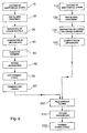
- Figures 2 to 8 illustrate a method of manufacturing a composite stringer according to the present invention. With reference to the flow chart of Figure 2, the method comprises the following steps.
- step 10 a plurality of metal strips 3 having the required length and width for the stringer being manufactured is prepared.
- the strips 3 are preferably produced by cutting a roll of sheet metal of suitable width.
- the sheet-metal strips 3 undergo a pre-gluing treatment in order to form an oxide layer on the surface of the strips, to permit improved anchorage of the adhesive to the metal.
- This treatment comprises anodizing by known methods, for example, with the use of phosphoric acid, and the application, by spraying, of a coating which is known in the art as a "primer" and has the function of protecting the oxide layer, which is well-known to be fragile, and of preventing corrosive processes at the metal-adhesive interface.
- the primer is subjected to a cross-linking process.
- step 30 the plurality of metal strips 3 and the plurality of fibre layers 4 are arranged alternately on a flat support surface 31 to produce a pile 32.
- a first metal strip 3 is deposited on the flat support surface 31 and then two or more superimposed layers 4 of fibre, pre-impregnated with resin, are deposited on top of the metal strip.
- the glass-fibre layers are preferably arranged with the fibres oriented parallel to the longitudinal axis of the strip 3.
- step 40 the pile 32 is compacted by a vacuum bag.
- This operation takes place by fitting a vacuum bag 41 on the pile 32 and depressurizing the bag 41. This eliminates any air bubbles present in the layers containing the resin and brings about temporary adhesion between the various layers of the pile 32, facilitating handling of the multi-layered pile in the compacted condition.
- step 50 the pile 32 is bent in a manner such that its cross-section adopts a predetermined shape.
- This operation preferably takes place with the use of a device comprising a punch 51 and a die 52 each having one or more series of adjacent inclined surfaces 51a, 51b, 51c and 52a, 52b, 52c, each of which is oriented at 90° to the adjacent inclined surface.
- the inclined surfaces 51a-51c of the punch 51 are arranged facing and parallel to the corresponding inclined surfaces 52a-52c of the die 52 so that, when the punch 51 is closed onto the die 52 ( Figure 7), the piles 32 interposed between the inclined surfaces are deformed, reproducing the shape of the inclined surfaces between which they are clamped.
- the cavities of the punch and of the die have the final shape which the stiffening element is to have.
- the punch 51 and the die 52 are constructed for treating two piles 32 simultaneously, in order to produce two respective stringers having a cross-section defined herein as "Z"-shaped.
- step 60 once the punch and the die are closed onto the pile (or piles) 32, as shown schematically in Figure 7, a vacuum bag 61 is fitted on the assembly formed by the punch and the die closed onto the pile or piles 32.
- the bending operation may alternatively be performed by means of a bending machine with a blade 53, as shown schematically in Figure 6.
- the subsequent step of curing in an autoclave may be performed with the already-bent piles arranged between the punch 51 and the die 52, or by placing them on the punch 51 alone and fitting the vacuum bag onto them directly.
- the vacuum bag 61 is depressurized and, in step 70, the vacuum bag 61 with the piles 32 bent and held between the punch and the die, is introduced into an autoclave (not shown), with the application of heat and pressure so as to bring about curing of the resin impregnating the fibre layers 4 and to set the shape of the cross-section of the stringer 1 in accordance with the shape of the cavities of the punch and of the die.
- step 80 the stringer 1 removed from the punch is trimmed and faced.
- the trimming serves to remove the steps which are created in the lateral edges of the various metal layers 3, which become offset during the forming stage.
- the trimming may be performed mechanically with the use, for example, of a disk-type milling cutter (not shown) with polycrystalline inserts, or of a tungsten-carbide ball-end mill 72, or by other methods, not shown, for example, by laser means.
- the facing (not shown) enables the ends of the stringer 1 to be cut to produce exactly the required length.
- the composite stringer 1 thus obtained can be fixed to the already-cured outer skin of hybrid composite material, for example, by riveting, or by gluing with a structural adhesive.
- the assembly formed by the outer skin 5 and one or more stringers 1 will have to be subjected to a thermal cycle to cure the adhesive.
- Figure 13 shows a cross-section of the element for stiffening the outer skin and of a tool which can be used for locating and gluing together these two elements.
- a method of this type provides for the same steps as those described with reference to Figure 2, up to step 60 for the fitting of the vacuum bag 61. The description of these steps will not be repeated here.
- the next step 70' provides for a hot-forming cycle in which heat and pressure are applied to the assembly inside the bag 61 so as to promote cohesion of the layers by means of the adhesive present in the plurality of fibre layers 4.
- This step is performed in order to consolidate the shaped pile as much as possible to facilitate its handling in the subsequent processing steps; the maximum temperature reached in this step 70' is selected so as to fluidize the adhesive without polymerizing it.
- Step 80' which is optional, provides for trimming and facing of the consolidated piles removed from the punch, as described with reference to Figure 2.
- the preparation or laying-up of the skin panel 5 is performed in parallel with that of the stringer 1.
- step 110 a plurality of metal strips 5a are prepared, preferably by cutting portions from a sheet-metal roll of suitable width.
- the next step 120 provides for a pre-gluing treatment of the surface of the metal strips, by methods similar to those described with reference to step 20 in Figure 2.
- step 130 the metal layers 5a and the fibre layers 5b are arranged alternately, with the interposition of two or more superimposed layers 5b of adhesive-impregnated fibres between two consecutive metal strips 5a.
- the various layers are placed in succession on a support surface, indicated 216 in Figure 10A and having a surface identical to the aerodynamic profile of the fuselage panel under construction, to produce the desired layering of the outer skin.
- the metal strips 5a are placed with their longer dimensions oriented in a circumferential direction, with reference to the geometry of the fuselage under construction.
- step 140 the outer-skin laminate is compacted in a vacuum bag, in known manner.
- step 200 Upon completion of the laying-up of the stringers 1 and of the skin 5 in parallel, in step 200, a layer of structural adhesive is applied between each shaped and consolidated pile 32 of the stringers 1 and the surface 207 of the semi-finished panel.
- rigid locating bars 219 are combined with each pile 32 in order to position it on the semi-finished panel 215 in a manner such as to keep the shaped pile, which has not yet been stiffened, in the exact desired shape and position.
- a vacuum bag 211 is fitted on the assembly formed by the bars 219 with the piles 32 and by the semi-finished panel 215, supported by the support 216 with a curved surface.
- step 220 heat and pressure are applied to the assembly thus formed in the vacuum bag so as simultaneously to cure both the adhesive of the laminates and that which is to bond the stringers 1 to the panel 5, thus producing the skin panel 5, reinforced with the stringers 1.
- This operation is performed by introducing the assembly contained in the vacuum bag into an autoclave where it is subjected to a thermal cycle similar to that of step 70 of the flow chart of Figure 2.
- the method shown in the flow chart of Figure 9 is particularly advantageous, since it enables both the resin in the layers of the stringers and the resin in the layers of the panel, as well as the adhesive interposed between the stringers and the panel, to be cured in a single autoclave cycle.
- Figure 10B shows a different tool for positioning the stiffening elements relative to the outer skin.
- This alternative method differs from the method of Figure 9 substantially in that it provides for two separate autoclave curing cycles, more precisely, a first cycle for curing the resin between the layers of the stringers and a second cycle for gluing the stringers to the panel, with simultaneous curing of the resin between the layers of the panel.
- steps 10 to 80 defined in the flow chart of Figure 2 are followed to produce one or more stringers ready to be fitted on the skin laminate, which has not yet been cured.
- step 110 a plurality of metal strips 5a is prepared, preferably by cutting a roll of sheet-metal of suitable width.
- the next step 120 provides for a pre-gluing treatment of the surface of the metal strips by methods similar to those described with reference to step 20.
- step 130 the metal strips 5a and the fibre layers 5b are arranged alternately, with the interposition of two or more superimposed layers 5b of resin-impregnated fibre between two consecutive metal strips 5a.
- the various layers are placed in succession on a curved support, indicated 216 in Figure 13 and having a curvature corresponding to that of the fuselage under construction, to produce a semi-finished laminate with the desired layering for the skin.
- the metal strips 5a are placed with their longer dimensions oriented in a circumferential direction, with reference to the geometry of the fuselage under construction.
- step 140 the semi-finished laminate is compacted with a vacuum bag.
- step 200 a layer of structural adhesive is applied between each already-cured stringer 1 and the surface portions of the semi-finished laminate (not yet cured) to which the stringers are to be fixed.
- a vacuum bag 211 is fitted on the assembly formed by the stringers 1 on the semi-finished panel 215, supported by the curved support 216.
- a series of rigid locating bars 219a, 219b, 219c is fitted against the stringers and restrains the stringers in the correct design configuration.
- step 220 heat and pressure are applied to the assembly thus formed in the vacuum bag so as to cure simultaneously both the resin between the layers of the outer skin and the adhesive which is to bond the components together, thus producing a skin panel 5 reinforced with the stiffening elements 1.
- This operation is performed by introducing the vacuum bag into an autoclave in which it is subjected to a thermal cycle similar to that described with reference to step 70 of the flow chart of Figure 2.
- Figures 14 and 15 show stringer variants with L-shaped cross-sections, particularly for use in pairs by placing the two L-shaped stringers in an opposed arrangement with their vertical flanges facing one another and joined together by a predetermined amount of structural adhesive between the two vertical flanges 1a of the two L-shaped stringers.
- one of the two stringers has a transversely thickened portion 1d in the region of its free end. This portion has a laminated structure identical to the remaining portion of the stringer.
- two separate bars 219a' and 219a" are used (acting on the side of the stringer which has the thickened portion 1d).
- the lower lateral bar 219a” acts against the lower portion of the flange 1a in order to cooperate with the opposed bar 219b to clamp the vertical flanges 1a;
- the upper lateral bar 219a' which is movable horizontally independently of the lower lateral bar 219a", serves to clamp the thickened portion 1d.
- the autoclave pressure acts on the bars 219a', 219a" and 219b and, by means of these, enables the elements 1d to be glued to the element 1a and the vertical flanges 1a to be glued together.
- This splitting of the bars is preferable to the selection of using a single bar on the side provided with the thickening since it can compensate for play due to dimensional tolerances of the elements making up the stringers and/or of the locating bars themselves.
- An upper cover 219c urges the bars 219a', 219a" and 219b against the base flanges 1b of the stringers and enables the pressure required for the gluing to the surface of the panel to be applied to these flanges.
- the base flanges 1b of the stringers will preferably have a portion of greater width (not shown) in the regions in which the stringers intersect the fuselage frames.
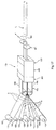
- Figure 17 shows schematically a plant for the manufacture of the composite stringers by a method which has aspects similar to pultrusion.
- This method provides for the continuous processing of a plurality of rolls of sheet-metal strip, which has already been subjected to a continuous pre-gluing treatment comprising a preliminary treatment with phosphoric acid and subsequent application of a primer, and a plurality of rolls of unidirectional fibre pre-impregnated with resin.
- the plant comprises a section provided with reels 105 which can allow the plurality of rolls of sheet-metal strip 103 and the plurality of rolls of unidirectional pre-impregnated fibre 104 to unwind, a pre-forming section 150, a section 170 for the application of heat and pressure, a trimming section 181, and a facing section 182.
- the functions of these sections will be described further below.
- the pre-forming section 150 and the section 170 for the application of heat and pressure comprise two opposed groups of shaped roller pressing means 190 or, more preferably, shaped belt pressing means (so as to prevent slippage of the roller relative to the sheet-metal) which, by their rotary motion, can exert a pressure on the sheet-metal strips and on the fibre introduced simultaneously between these groups, shaping them in accordance with a predetermined shape.
- the section 170 for the application of heat and pressure is divided into a heating section 201, a holding section 202, and a cooling section 203, comprising heating means and cooling means (not shown) that can perform a cooling cycle which is optimal for the cross-linking of the resin.
- the section 150 performs the superposition and bending of the layers
- the sections 201, 202 and 203 may alternatively perform a complete curing cycle (as in step 70 of figure 2) or simply a hot forming cycle (as in step 70' of Figure 9); the sections 181 and 182 perform the trimming and facing (as in step 80 of Figures 2 and 9).
- the method illustrated in Figure 17 does not require the use of a vacuum bag, the compacting effect being achieved by virtue of the action of the pressing means 190.
- a plant of this type may also be able to supply consolidated (but not cured) hybrid composite laminate stiffening elements suitable for being glued to a semi-finished skin panel to be subjected to curing subsequently, as is provided for in the method represented by the flow chart of Figure 9.
- the embodiments described are intended as examples of the implementation of the invention but the invention may undergo modifications in relation to the shape and arrangement of parts, or to structural and functional details in accordance with the many possible variants which may seem appropriate to persons skilled in the art.
- the method according to the invention could be used for the manufacture of encircling elements, known as bulkheads or frames, which are fixed to the inner surface of the fuselage transversely.
- the adhesive material may be thermosetting or thermoplastic
- the metal layers may be of aluminium or alloys thereof, or of any other suitable material.
Landscapes
- Engineering & Computer Science (AREA)
- Mechanical Engineering (AREA)
- Chemical & Material Sciences (AREA)
- Composite Materials (AREA)
- Architecture (AREA)
- Civil Engineering (AREA)
- Structural Engineering (AREA)
- Moulding By Coating Moulds (AREA)
- Laminated Bodies (AREA)
- Casting Or Compression Moulding Of Plastics Or The Like (AREA)
Abstract
A method of manufacturing a stringer (1) for a fuselage skin
panel comprises the steps of:
- preparing a pile (32) of sheet-metal strips (3) bent so as to have a cross-section of given shape, alternating with at least one layer of resin-impregnated fibre (4), and
- applying heat and pressure (70) to the pile (32) in a manner such as to cure the resin and set the shape.
A composite laminated stringer is thus obtained.
In order to manufacture a fuselage panel of composite
laminated material, provided with composite laminated
stringers, the resin in the stringers is cured
simultaneously with the resin which is present between the
metal layers of a laminate suitable for forming the outer
skin.
Description
- The present invention relates to methods of manufacturing a stiffening element for an aircraft skin panel, for example, a stringer for a fuselage panel. The invention also relates to methods of manufacturing a skin panel provided with such stiffening elements.
- Stiffening elements, also commonly known as stringers, are known and are constituted substantially by elongate elements made of aluminium or of metal having similar mechanical characteristics, which have a cross-section (usually Z-shaped, L-shaped or hook-shaped) that can ensure a predetermined stiffness of the panel to which they are fixed.
- It is also known that the skin panels which form the upper portion of an aircraft fuselage can be formed as laminates of so-called hybrid composite material, known in the field by the term GLARE® or FML (fibre-metal laminate), comprising a plurality of layers of metal, for example, aluminium or light alloy, alternating with a plurality of layers of fibre having high mechanical characteristics, for example, glass fibre, impregnated with a structural adhesive, for example, epoxy resin.
- A laminated panel of this type is disclosed, for example, in EP A-0 649 373.
- Although FML panels already enable good mechanical performance to be achieved with a relatively low weight, the aeronautical industry is oriented towards the production of components which enable the overall weight of aircraft to be reduced further, for given performance.
- According to a first aspect of the invention, a method of manufacturing stiffening elements as defined in
Claim 1 is therefore proposed. - According to another aspect of the invention, two methods of manufacturing a skin panel provided with improved stiffening elements as defined in Claims 8 and 11 are proposed.
- Some preferred but non-limiting embodiments of the invention will now be described with reference to the appended drawings, in which:
- Figure 1 is a schematic cross-section view through an improved stiffening element produced by a method according to the present invention,
- Figure 2 is a flow chart which shows the steps of a method of manufacturing a stiffening element in accordance with the invention,
- Figures 3 to 8 show schematically some steps of the method of Figure 2,
- Figure 9 is a flow chart which shows the steps of a method of manufacturing a skin panel provided with improved stiffening elements according to the invention,
- Figures 10A and 10B are cross-section views through a panel with stiffening elements, during a step of its manufacture,
- Figure 11 is a schematic cross-section view similar to Figure 1, of a variant of the panel according to the invention,
- Figure 12 is a flow chart which shows the steps of another method of manufacturing a skin panel provided with improved stiffening elements according to the invention,
- Figure 13 is a cross-section view through a panel with stiffening elements, during a step of its manufacture,
- Figures 14 and 15 are two schematic cross-section views of two alternative embodiments of stiffening elements according to the invention,
- Figure 16 is a cross-section view through a panel provided with a stiffening element according to Figure 15, during a step of its manufacture, and
- Figure 17 shows schematically a plant for the continuous manufacture of stiffening elements according to the invention.
-
- With reference to Figure 1, a longitudinal stiffening element or stringer 1 of hybrid composite material and having a substantially Z-shaped cross-section is shown. As a person skilled in the art will appreciate, this shape is provided purely by way of example and the invention is equally applicable to sections of shapes other than that shown.
- The
stringer 1 comprises a plurality ofmetal layers 3 constituted by strips of aluminium or light-alloy sheet, alternating with a plurality of layers offibre 4 with good mechanical characteristics, for example, glass fibre or aramid fibre, pre-impregnated, in known manner, with a resin, for example, epoxy resin, so as to bond the metal layers firmly. - In the embodiment of Figure 1, three
metal layers 3 and twofibre layers 4 are shown. The ratio between the number of metal layers and the number of fibre layers is preferably between 2:1 and 5:4 or more, and is selected in a manner such that the outermost layers are always metal. In any case, the number and dimensions of the metal layers and of the fibre layers are selected on the basis of the maximum stresses which thestringer 1 will have to withstand. - The
metal layers 3 are preferably made of sheet metal having a thickness, for example, of between 0.2 and 0.4 mm. Each of thefibre layers 4 is preferably formed by a double layer of fibre, arranged parallel to the longitudinal axis of thestringer 1. - A stiffening element thus constructed is fixed to the inner surface of a panel, generally indicated 5, by the methods which will be described below. In the embodiment described herein, the
panel 5 is a fuselage skin panel. Naturally, reference to this possible area of use should not be interpreted as in any way limiting of the scope of the patent. For example, the invention is equally applicable to the construction of wing panels. - In the preferred embodiment of the present invention, the
composite stringer 1 is fixed to thepanel 5 by means of a layer of structural adhesive, indicated 6. Alternatively, thecomposite stringer 1 may be fixed to thepanel 5 by another method, for example, by riveting. - The laminated
skin panel 5 shown in Figure 1 is an FML panel comprising a plurality ofmetal layers 5a alternating with a plurality oflayers 5b of fibre pre-impregnated with resin. The general structure of the GLARE panel shown in Figure 1 may be considered generally known. Thepanel 5 will not therefore be described in greater detail below. For the construction of a panel of this type, reference may therefore be made, for example, to EP-A-0 649 373. - Figures 2 to 8 illustrate a method of manufacturing a composite stringer according to the present invention. With reference to the flow chart of Figure 2, the method comprises the following steps.
- In
step 10, a plurality ofmetal strips 3 having the required length and width for the stringer being manufactured is prepared. Thestrips 3 are preferably produced by cutting a roll of sheet metal of suitable width. - In the
next step 20, the sheet-metal strips 3 undergo a pre-gluing treatment in order to form an oxide layer on the surface of the strips, to permit improved anchorage of the adhesive to the metal. This treatment comprises anodizing by known methods, for example, with the use of phosphoric acid, and the application, by spraying, of a coating which is known in the art as a "primer" and has the function of protecting the oxide layer, which is well-known to be fragile, and of preventing corrosive processes at the metal-adhesive interface. After application, the primer is subjected to a cross-linking process. - In
step 30, and as shown schematically in Figure 3, the plurality ofmetal strips 3 and the plurality offibre layers 4 are arranged alternately on aflat support surface 31 to produce apile 32. During this operation, afirst metal strip 3 is deposited on theflat support surface 31 and then two or moresuperimposed layers 4 of fibre, pre-impregnated with resin, are deposited on top of the metal strip. The glass-fibre layers, the number of which is variable according to requirements, are preferably arranged with the fibres oriented parallel to the longitudinal axis of thestrip 3. These alternating depositions ofmetal strips 3 andfibre layers 4 are repeated until a predetermined number of layers is reached, upon the condition that the two outermost layers of the pile are constituted by metal strips. - In
step 40, and as shown schematically in Figure 4, thepile 32 is compacted by a vacuum bag. This operation takes place by fitting avacuum bag 41 on thepile 32 and depressurizing thebag 41. This eliminates any air bubbles present in the layers containing the resin and brings about temporary adhesion between the various layers of thepile 32, facilitating handling of the multi-layered pile in the compacted condition. - Then, in
step 50 and as shown schematically in Figure 5, thepile 32 is bent in a manner such that its cross-section adopts a predetermined shape. This operation preferably takes place with the use of a device comprising apunch 51 and adie 52 each having one or more series of adjacentinclined surfaces inclined surfaces 51a-51c of thepunch 51 are arranged facing and parallel to the correspondinginclined surfaces 52a-52c of thedie 52 so that, when thepunch 51 is closed onto the die 52 (Figure 7), thepiles 32 interposed between the inclined surfaces are deformed, reproducing the shape of the inclined surfaces between which they are clamped. In other words, the cavities of the punch and of the die have the final shape which the stiffening element is to have. In the embodiment of Figure 7, thepunch 51 and the die 52 are constructed for treating twopiles 32 simultaneously, in order to produce two respective stringers having a cross-section defined herein as "Z"-shaped. - In
step 60, once the punch and the die are closed onto the pile (or piles) 32, as shown schematically in Figure 7, avacuum bag 61 is fitted on the assembly formed by the punch and the die closed onto the pile orpiles 32. - It should be noted that the bending operation may alternatively be performed by means of a bending machine with a
blade 53, as shown schematically in Figure 6. The subsequent step of curing in an autoclave may be performed with the already-bent piles arranged between thepunch 51 and thedie 52, or by placing them on thepunch 51 alone and fitting the vacuum bag onto them directly. - The
vacuum bag 61 is depressurized and, instep 70, thevacuum bag 61 with thepiles 32 bent and held between the punch and the die, is introduced into an autoclave (not shown), with the application of heat and pressure so as to bring about curing of the resin impregnating thefibre layers 4 and to set the shape of the cross-section of thestringer 1 in accordance with the shape of the cavities of the punch and of the die. - In
step 80, as shown schematically in Figure 8, thestringer 1 removed from the punch is trimmed and faced. The trimming serves to remove the steps which are created in the lateral edges of thevarious metal layers 3, which become offset during the forming stage. The trimming may be performed mechanically with the use, for example, of a disk-type milling cutter (not shown) with polycrystalline inserts, or of a tungsten-carbide ball-end mill 72, or by other methods, not shown, for example, by laser means. The facing (not shown) enables the ends of thestringer 1 to be cut to produce exactly the required length. - At this point, the
composite stringer 1 thus obtained can be fixed to the already-cured outer skin of hybrid composite material, for example, by riveting, or by gluing with a structural adhesive. In the latter case, the assembly formed by theouter skin 5 and one ormore stringers 1 will have to be subjected to a thermal cycle to cure the adhesive. Figure 13 shows a cross-section of the element for stiffening the outer skin and of a tool which can be used for locating and gluing together these two elements. - Although the method shown in the flow chart of Figure 2 is the preferred embodiment, the same result can be achieved by changing the order of some steps, that is, by first bending the metal strips and then applying the fibre-reinforced adhesive layers between the already-bent strips.
- A method of manufacturing an FML laminated panel, for example, a fuselage skin panel, provided with one or more stringers of composite laminate material as described above is described, with reference to Figure 9.
- With regard to the manufacture of the stringers, a method of this type provides for the same steps as those described with reference to Figure 2, up to step 60 for the fitting of the
vacuum bag 61. The description of these steps will not be repeated here. - The next step 70' provides for a hot-forming cycle in which heat and pressure are applied to the assembly inside the
bag 61 so as to promote cohesion of the layers by means of the adhesive present in the plurality of fibre layers 4. This step is performed in order to consolidate the shaped pile as much as possible to facilitate its handling in the subsequent processing steps; the maximum temperature reached in this step 70' is selected so as to fluidize the adhesive without polymerizing it. - Step 80', which is optional, provides for trimming and facing of the consolidated piles removed from the punch, as described with reference to Figure 2.
- The preparation or laying-up of the
skin panel 5 is performed in parallel with that of thestringer 1. - In
step 110, a plurality ofmetal strips 5a are prepared, preferably by cutting portions from a sheet-metal roll of suitable width. - The
next step 120 provides for a pre-gluing treatment of the surface of the metal strips, by methods similar to those described with reference to step 20 in Figure 2. - Then, in
step 130, themetal layers 5a and the fibre layers 5b are arranged alternately, with the interposition of two or moresuperimposed layers 5b of adhesive-impregnated fibres between twoconsecutive metal strips 5a. The various layers are placed in succession on a support surface, indicated 216 in Figure 10A and having a surface identical to the aerodynamic profile of the fuselage panel under construction, to produce the desired layering of the outer skin. The metal strips 5a are placed with their longer dimensions oriented in a circumferential direction, with reference to the geometry of the fuselage under construction. - In
step 140, the outer-skin laminate is compacted in a vacuum bag, in known manner. - Upon completion of the laying-up of the
stringers 1 and of theskin 5 in parallel, instep 200, a layer of structural adhesive is applied between each shaped andconsolidated pile 32 of thestringers 1 and thesurface 207 of the semi-finished panel. - Again with reference to Figure 10A, rigid locating
bars 219 are combined with eachpile 32 in order to position it on thesemi-finished panel 215 in a manner such as to keep the shaped pile, which has not yet been stiffened, in the exact desired shape and position. - In
step 210, and as shown in Figure 10A, avacuum bag 211 is fitted on the assembly formed by thebars 219 with thepiles 32 and by thesemi-finished panel 215, supported by thesupport 216 with a curved surface. - In
step 220, heat and pressure are applied to the assembly thus formed in the vacuum bag so as simultaneously to cure both the adhesive of the laminates and that which is to bond thestringers 1 to thepanel 5, thus producing theskin panel 5, reinforced with thestringers 1. This operation is performed by introducing the assembly contained in the vacuum bag into an autoclave where it is subjected to a thermal cycle similar to that ofstep 70 of the flow chart of Figure 2. - As will be appreciated, the method shown in the flow chart of Figure 9 is particularly advantageous, since it enables both the resin in the layers of the stringers and the resin in the layers of the panel, as well as the adhesive interposed between the stringers and the panel, to be cured in a single autoclave cycle.
- Figure 10B shows a different tool for positioning the stiffening elements relative to the outer skin.
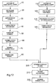
- An alternative method of manufacturing an FML laminated panel provided with one or more stringers of hybrid composite laminate material of the type described above will now be described with reference to the flow chart of Figure 12.
- This alternative method differs from the method of Figure 9 substantially in that it provides for two separate autoclave curing cycles, more precisely, a first cycle for curing the resin between the layers of the stringers and a second cycle for gluing the stringers to the panel, with simultaneous curing of the resin between the layers of the panel.
- According to this alternative method, to manufacture the stringers, steps 10 to 80 defined in the flow chart of Figure 2 are followed to produce one or more stringers ready to be fitted on the skin laminate, which has not yet been cured.
- In
step 110, a plurality ofmetal strips 5a is prepared, preferably by cutting a roll of sheet-metal of suitable width. - The
next step 120 provides for a pre-gluing treatment of the surface of the metal strips by methods similar to those described with reference to step 20. - Then, in
step 130, the metal strips 5a and the fibre layers 5b are arranged alternately, with the interposition of two or moresuperimposed layers 5b of resin-impregnated fibre between twoconsecutive metal strips 5a. The various layers are placed in succession on a curved support, indicated 216 in Figure 13 and having a curvature corresponding to that of the fuselage under construction, to produce a semi-finished laminate with the desired layering for the skin. The metal strips 5a are placed with their longer dimensions oriented in a circumferential direction, with reference to the geometry of the fuselage under construction. - In
step 140, the semi-finished laminate is compacted with a vacuum bag. - In
step 200, a layer of structural adhesive is applied between each already-curedstringer 1 and the surface portions of the semi-finished laminate (not yet cured) to which the stringers are to be fixed. - In
step 210, as shown in Figure 13, avacuum bag 211 is fitted on the assembly formed by thestringers 1 on thesemi-finished panel 215, supported by thecurved support 216. In order for the stringers to retain the correct design geometry and, in particular, to prevent the bent portions of the stringer from tending to open out resiliently, losing the 90° inclination which they acquired in the cross-linking stage, a series ofrigid locating bars - In
step 220, heat and pressure are applied to the assembly thus formed in the vacuum bag so as to cure simultaneously both the resin between the layers of the outer skin and the adhesive which is to bond the components together, thus producing askin panel 5 reinforced with thestiffening elements 1. This operation is performed by introducing the vacuum bag into an autoclave in which it is subjected to a thermal cycle similar to that described with reference to step 70 of the flow chart of Figure 2. - In the embodiments described up to now, stringers with Z-shaped cross-sections have been described. Figures 14 and 15 show stringer variants with L-shaped cross-sections, particularly for use in pairs by placing the two L-shaped stringers in an opposed arrangement with their vertical flanges facing one another and joined together by a predetermined amount of structural adhesive between the two
vertical flanges 1a of the two L-shaped stringers. - In the variant of Figure 15, in order to increase the moment of inertia of the resisting cross-section of the stringer, one of the two stringers has a transversely thickened
portion 1d in the region of its free end. This portion has a laminated structure identical to the remaining portion of the stringer. - During the curing cycle in the autoclave, as shown in Figure 16, two
separate bars 219a' and 219a" are used (acting on the side of the stringer which has the thickenedportion 1d). The lowerlateral bar 219a" acts against the lower portion of theflange 1a in order to cooperate with theopposed bar 219b to clamp thevertical flanges 1a; the upperlateral bar 219a', which is movable horizontally independently of the lowerlateral bar 219a", serves to clamp the thickenedportion 1d. The autoclave pressure acts on thebars 219a', 219a" and 219b and, by means of these, enables theelements 1d to be glued to theelement 1a and thevertical flanges 1a to be glued together. This splitting of the bars is preferable to the selection of using a single bar on the side provided with the thickening since it can compensate for play due to dimensional tolerances of the elements making up the stringers and/or of the locating bars themselves. Anupper cover 219c urges thebars 219a', 219a" and 219b against thebase flanges 1b of the stringers and enables the pressure required for the gluing to the surface of the panel to be applied to these flanges. - Irrespective of the shape of cross-section selected, the
base flanges 1b of the stringers will preferably have a portion of greater width (not shown) in the regions in which the stringers intersect the fuselage frames. - Figure 17 shows schematically a plant for the manufacture of the composite stringers by a method which has aspects similar to pultrusion. This method provides for the continuous processing of a plurality of rolls of sheet-metal strip, which has already been subjected to a continuous pre-gluing treatment comprising a preliminary treatment with phosphoric acid and subsequent application of a primer, and a plurality of rolls of unidirectional fibre pre-impregnated with resin. The plant comprises a section provided with
reels 105 which can allow the plurality of rolls of sheet-metal strip 103 and the plurality of rolls of unidirectionalpre-impregnated fibre 104 to unwind, apre-forming section 150, asection 170 for the application of heat and pressure, atrimming section 181, and a facingsection 182. The functions of these sections will be described further below. - The
pre-forming section 150 and thesection 170 for the application of heat and pressure comprise two opposed groups of shaped roller pressing means 190 or, more preferably, shaped belt pressing means (so as to prevent slippage of the roller relative to the sheet-metal) which, by their rotary motion, can exert a pressure on the sheet-metal strips and on the fibre introduced simultaneously between these groups, shaping them in accordance with a predetermined shape. Thesection 170 for the application of heat and pressure is divided into aheating section 201, a holdingsection 202, and acooling section 203, comprising heating means and cooling means (not shown) that can perform a cooling cycle which is optimal for the cross-linking of the resin. - The operation of a plant of this type provides for portions of strip to be unwound from the respective rolls and to enter the various sections in succession, moved by known means. In each section, they are subjected to steps similar to those described above with reference to Figure 2.
- In particular, the
section 150 performs the superposition and bending of the layers, thesections step 70 of figure 2) or simply a hot forming cycle (as in step 70' of Figure 9); thesections step 80 of Figures 2 and 9). The method illustrated in Figure 17 does not require the use of a vacuum bag, the compacting effect being achieved by virtue of the action of thepressing means 190. - As will be appreciated, a plant of this type may also be able to supply consolidated (but not cured) hybrid composite laminate stiffening elements suitable for being glued to a semi-finished skin panel to be subjected to curing subsequently, as is provided for in the method represented by the flow chart of Figure 9.
- The embodiments described are intended as examples of the implementation of the invention but the invention may undergo modifications in relation to the shape and arrangement of parts, or to structural and functional details in accordance with the many possible variants which may seem appropriate to persons skilled in the art. For example, instead of the manufacture of longitudinal stiffening elements, the method according to the invention could be used for the manufacture of encircling elements, known as bulkheads or frames, which are fixed to the inner surface of the fuselage transversely. Similarly, the adhesive material may be thermosetting or thermoplastic, and the metal layers may be of aluminium or alloys thereof, or of any other suitable material.
Claims (13)
- A method of manufacturing an elongate stiffening element(1) for an aircraft skin panel, comprising the following steps:a) preparing a pile (32) of sheet-metal strips (3) bent so as to have a cross-section of given shape, with at least one layer of resin-impregnated fibre (4) interposed between two consecutive sheet-metal strips, andb) applying heat and pressure (70) to the pile (32) thus produced in a manner such as to cure the resin and set the shape.
- A method according to Claim 1 in which step a) includes the steps of:a1) piling up the sheet-metal strips (3) substantially flat,a2) applying the at least one layer of resin-impregnated fibre (4), anda3) bending the sheet-metal strips (3) to the said shape.
- A method according to Claim 2 in which the bending step (a3) is performed by placing the pile (32) of sheet-metal strips (3) alternating with the fibre layers (4) in a forming die (51, 52), and in which the curing step (b) is performed with the use of the same die (51, 52) to keep the pile (32) in the desired shape.
- A method according to Claim 2 in which step (a3) is preceded by the step of:fitting a vacuum bag (61) on the pile (32) and depressurizing the vacuum bag in order to compact and temporarily hold the strips which are piled up in an orderly manner.
- A method according to Claim 1 in which at least one of said steps (a, b) is performed with the use of pairs of pressing means (190) in continuous rotary motion, acting on opposed faces of a pile (32) of sheet-metal strips (3) in which at least one layer of resin-impregnated fibre (4) is interposed between two consecutive sheet-metal strips.
- A method according to Claim 5 in which the pressing means (190) comprise belt means.
- A method according to Claim 5 which includes the step (70') of applying heat and pressure to the pile (32) so as to fluidize the adhesive in the fibre layers (4) without curing it.
- A method of manufacturing an aircraft skin panel with elongate stiffening elements, comprising the steps of:a') preparing at least one pile (32) of sheet-metal strips (3) bent so as to have a cross-section of given shape, with at least one layer of resin-impregnated fibre (4) interposed between two consecutive sheet-metal strips,b') preparing a laminate (215) suitable for forming the outer skin, the laminate (215) comprising at least two sheet-metal layers (5a) with at least one layer (5b) of resin-impregnated fibre interposed between two consecutive sheet-metal layers,c') arranging the at least one pile (32) on the skin laminate (215) with a layer of adhesive (200) interposed between the pile (32) and the skin laminate (215), andd') applying heat and pressure (220) in a manner such as simultaneously to cure the resin contained in the fibre layers of the pile (32) and of the laminate (215), and the adhesive interposed between the pile and the laminate (215).
- A method according to Claim 8 in which the polymerization step (d') includes the step of positioning rigid locating elements (219) associated with the piles (32) in order to keep the piles (32) in the desired shape and position during the curing cycle.
- A method according to Claim 8 in which step (a') is followed by the step (70') of applying heat and pressure to the pile (32) so as to fluidize the resin in the fibre layers (4) without curing it.
- A method of manufacturing an aircraft skin panel with elongate stiffening elements, comprising the steps of:a") preparing at least one pile (32) of sheet-metal strips (3) bent so as to have a cross-section of given shape, with at least one layer of resin-impregnated fibre (4) interposed between two consecutive sheet-metal strips,b") applying heat and pressure (70) to the pile (32) thus produced in a manner such as to cure the resin and set the shape so as to produce at least one elongate, composite, rigid element (1),c") preparing a laminate (215) suitable for forming the outer skin, the laminate comprising at least two sheet-metal layers (5a) with at least one layer of resin-impregnated fibre (5b) interposed between two consecutive sheet-metal layers,d") arranging the elongate rigid element (1) on the laminate (215), with a layer of adhesive (200) interposed between the elongate element (1) and the laminate (215), ande") applying heat and pressure (220) in a manner such as simultaneously to cure the resin contained in the fibre layers of the laminate (215) and the adhesive interposed between the elongate element (1) and the laminate (215).
- An elongate stiffening element (1) for an aircraft skin panel, in which the element comprises a pile of sheet-metal strips bent so as to have a cross-section of given shape, with at least one layer of resin-impregnated fibre interposed between two consecutive sheet-metal strips.
- An aircraft skin panel comprising at least one elongate stiffening element according to Claim 12.
Priority Applications (6)
| Application Number | Priority Date | Filing Date | Title |
|---|---|---|---|
| EP02425082A EP1336469A1 (en) | 2002-02-19 | 2002-02-19 | Methods of manufacturing a stiffening element for an aircraft skin panel and a skin panel provided with the stiffening element |
| US10/348,815 US20030168555A1 (en) | 2002-02-19 | 2003-01-22 | Methods of manufacturing a stiffening element for an aircraft skin panel and a skin panel provided with the stiffening element |
| CA002417072A CA2417072A1 (en) | 2002-02-19 | 2003-01-23 | Methods of manufacturing a stiffening element for an aircraft skin panel and a skin panel provided with the stiffening element |
| JP2003032498A JP2003312590A (en) | 2002-02-19 | 2003-02-10 | Reinforcement body for aircraft skin panel and manufacturing method for skin panel provided with reinforcement body |
| BR0300588-7A BR0300588A (en) | 2002-02-19 | 2003-02-13 | Method for fabricating a beam for a fuselage cladding panel |
| KR10-2003-0010124A KR20030069113A (en) | 2002-02-19 | 2003-02-18 | Methods of manufacturing a stiffening element for an aircraft skin panel and a skin panel provided with the stiffening element |
Applications Claiming Priority (1)
| Application Number | Priority Date | Filing Date | Title |
|---|---|---|---|
| EP02425082A EP1336469A1 (en) | 2002-02-19 | 2002-02-19 | Methods of manufacturing a stiffening element for an aircraft skin panel and a skin panel provided with the stiffening element |
Publications (1)
| Publication Number | Publication Date |
|---|---|
| EP1336469A1 true EP1336469A1 (en) | 2003-08-20 |
Family
ID=27619216
Family Applications (1)
| Application Number | Title | Priority Date | Filing Date |
|---|---|---|---|
| EP02425082A Withdrawn EP1336469A1 (en) | 2002-02-19 | 2002-02-19 | Methods of manufacturing a stiffening element for an aircraft skin panel and a skin panel provided with the stiffening element |
Country Status (6)
| Country | Link |
|---|---|
| US (1) | US20030168555A1 (en) |
| EP (1) | EP1336469A1 (en) |
| JP (1) | JP2003312590A (en) |
| KR (1) | KR20030069113A (en) |
| BR (1) | BR0300588A (en) |
| CA (1) | CA2417072A1 (en) |
Cited By (31)
| Publication number | Priority date | Publication date | Assignee | Title |
|---|---|---|---|---|
| ES2246675A1 (en) * | 2003-12-30 | 2006-02-16 | Airbus España S.L. | Formation of a vacuum bag for autoclavable material consists of full surface contacting of sheet with the component prior to autoclaving, via guides protecting the component |
| WO2006118691A2 (en) * | 2005-04-28 | 2006-11-09 | The Boeing Company | Composite skin and stringer structures and methods for forming the same |
| WO2007071398A1 (en) * | 2005-12-20 | 2007-06-28 | Airbus Deutschland Gmbh | Protection device |
| WO2007077265A1 (en) * | 2005-12-30 | 2007-07-12 | Airbus España, S.L. | Method for producing panels of composite materials with u-shaped stiffening elements |
| WO2008053041A1 (en) * | 2006-11-03 | 2008-05-08 | Airbus Deutschland Gmbh | Stiffened casing for an aircraft or spacecraft with a laminate stringer of high rigidity and corresponding laminate stringer |
| EP1932757A1 (en) * | 2006-12-15 | 2008-06-18 | Airbus Deutschland GmbH | Bonded aluminium window frame on fibre metal laminate fuselage skin |
| WO2008094227A1 (en) * | 2007-01-29 | 2008-08-07 | The Boeing Company | Thermoplastic composite parts having integrated metal fittings and method of making the same |
| DE102007019716A1 (en) * | 2007-04-26 | 2008-10-30 | Airbus Deutschland Gmbh | Fiber metal laminate panel |
| US7467763B2 (en) | 2005-06-03 | 2008-12-23 | Kismarton Max U | Composite landing gear apparatus and methods |
| US7721495B2 (en) | 2005-03-31 | 2010-05-25 | The Boeing Company | Composite structural members and methods for forming the same |
| US7740932B2 (en) | 2005-03-31 | 2010-06-22 | The Boeing Company | Hybrid fiberglass composite structures and methods of forming the same |
| US7748119B2 (en) | 2005-06-03 | 2010-07-06 | The Boeing Company | Method for manufacturing composite components |
| WO2012007780A1 (en) | 2010-07-13 | 2012-01-19 | Learjet Inc. | Composite structure and method of forming same |
| NL2005667C2 (en) * | 2010-11-11 | 2012-05-14 | Univ Delft Tech | Method for fabrication of a fiber metal laminate. |
| US8333858B2 (en) | 2006-02-02 | 2012-12-18 | The Boeing Company | Method for fabricating curved thermoplastic composite parts |
| WO2013014288A1 (en) * | 2011-07-27 | 2013-01-31 | Airbus Operations Gmbh | A device for the manufacture of a bonded component from fibre-reinforced plastics, and also a method |
| US8425708B2 (en) | 2006-02-02 | 2013-04-23 | The Boeing Company | Continuous fabrication of parts using in-feed spools of fiber reinforced thermoplastic |
| US8491745B2 (en) | 2007-02-03 | 2013-07-23 | The Boeing Company | Method and material efficient tooling for continuous compression molding |
| DE102012003731A1 (en) | 2012-02-28 | 2013-08-29 | Deutsches Zentrum für Luft- und Raumfahrt e.V. | Semi-finished product for the production of a fiber composite metal hybrid laminate and method for producing such a semifinished product |
| EP2689918A1 (en) * | 2012-07-25 | 2014-01-29 | The Boeing Company | Laminated composite bending and stiffening members with reinforcement by inter-laminar metal sheets |
| US8678267B2 (en) | 2008-10-10 | 2014-03-25 | The Boeing Company | System and method for integrally forming a stiffener with a fiber metal laminate |
| US8691137B2 (en) | 2009-03-04 | 2014-04-08 | The Boeing Company | Method of molding partus using a tool sleeve for mold die |
| WO2014082929A1 (en) * | 2012-11-27 | 2014-06-05 | Thyssenkrupp Steel Europe Ag | Method for producing a structural component, particularly for a vehicle body |
| JP2014237259A (en) * | 2013-06-07 | 2014-12-18 | 三菱航空機株式会社 | Production method and mold for fiber-reinforced plastic structure |
| EP2905220A1 (en) * | 2014-02-06 | 2015-08-12 | The Boeing Company | Laminated I-blade stringer |
| RU2621760C2 (en) * | 2011-09-23 | 2017-06-07 | Хексел Композитс Лимитед | Conductive composite structure or laminate |
| US9878773B2 (en) | 2012-12-03 | 2018-01-30 | The Boeing Company | Split resistant composite laminate |
| US10232532B1 (en) | 2006-02-02 | 2019-03-19 | The Boeing Company | Method for fabricating tapered thermoplastic composite parts |
| US10449736B2 (en) | 2006-02-02 | 2019-10-22 | The Boeing Company | Apparatus for fabricating thermoplastic composite parts |
| RU2708862C1 (en) * | 2019-01-18 | 2019-12-11 | Публичное акционерное общество "Авиационная холдинговая компания "Сухой" | Method of making part and part from hybrid composite material |
| US10821653B2 (en) | 2010-02-24 | 2020-11-03 | Alexander M. Rubin | Continuous molding of thermoplastic laminates |
Families Citing this family (43)
| Publication number | Priority date | Publication date | Assignee | Title |
|---|---|---|---|---|
| DE10031510A1 (en) * | 2000-06-28 | 2002-01-17 | Airbus Gmbh | Structural component for an aircraft |
| EP1495859B1 (en) * | 2003-07-08 | 2008-09-03 | Airbus Deutschland GmbH | Lightweight material structure |
| US7052573B2 (en) * | 2003-11-21 | 2006-05-30 | The Boeing Company | Method to eliminate undulations in a composite panel |
| EP1666354B1 (en) * | 2004-12-01 | 2010-09-29 | Airbus Operations GmbH | Structural component, process for manufacturing a structural component and use of a structural component for an aircraft skin |
| US7837147B2 (en) | 2005-03-18 | 2010-11-23 | The Boeing Company | Systems and methods for reducing noise in aircraft fuselages and other structures |
| US8720825B2 (en) * | 2005-03-31 | 2014-05-13 | The Boeing Company | Composite stiffeners for aerospace vehicles |
| US20060222837A1 (en) * | 2005-03-31 | 2006-10-05 | The Boeing Company | Multi-axial laminate composite structures and methods of forming the same |
| US20060237588A1 (en) * | 2005-03-31 | 2006-10-26 | The Boeing Company | Composite structural member having an undulating web and method for forming the same |
| DE102006005189A1 (en) * | 2006-02-02 | 2007-08-09 | Uhde Gmbh | Method for producing coke with high volatile content in coking chamber of non recovery or heat recovery type coke oven, involves filling coking chamber with layer of coal, where cooling water vapor is introduced in coke oven |
| DE102006007429B4 (en) * | 2006-02-17 | 2011-08-18 | Airbus Operations GmbH, 21129 | Method for autoclave-free bonding of components for aircraft |
| DE102006031436B4 (en) * | 2006-07-07 | 2012-12-06 | Airbus Operations Gmbh | Structural element, method for producing such a structural element and aircraft with such a structural element |
| NL2000232C2 (en) * | 2006-09-12 | 2008-03-13 | Gtm Consulting B V | Skin panel for an aircraft fuselage. |
| US7997534B2 (en) * | 2006-10-13 | 2011-08-16 | Airbus Operations Gmbh | Connecting structure for an aircraft or spacecraft and method for producing the same |
| US8241448B2 (en) * | 2006-11-09 | 2012-08-14 | The Boeing Company | Film adhesive bonding apparatus and process |
| US9511571B2 (en) * | 2007-01-23 | 2016-12-06 | The Boeing Company | Composite laminate having a damping interlayer and method of making the same |
| DE102007018753B4 (en) * | 2007-04-20 | 2012-11-08 | Airbus Operations Gmbh | Fire protection room for aircraft passengers with the help of fuselage made of fiber-metal laminates |
| FR2921898B1 (en) * | 2007-10-08 | 2009-12-11 | Airbus France | FUSELAGE STRUCTURE FOR AIRCRAFT FUSELAGE IN COMPOSITE MATERIAL AND AIRCRAFT EQUIPPED WITH SUCH A FUSELAGE STRUCTURE |
| DE102008010228A1 (en) * | 2008-02-21 | 2009-09-03 | Airbus Deutschland Gmbh | Method and device for producing fiber-reinforced plastic profile parts |
| ITMI20080886A1 (en) * | 2008-05-15 | 2009-11-16 | Alenia Aermacchi Spa | JOINT TO INDUCE HIGH TEMPERATURE FALLS BETWEEN CONNECTED PARTS ON A AIRCRAFT |
| US8551382B2 (en) * | 2008-05-28 | 2013-10-08 | The Boeing Company | Modified blade stiffener and fabrication method therefor |
| DE102008042782A1 (en) * | 2008-10-13 | 2010-04-29 | Airbus Deutschland Gmbh | Structural element for reinforcing a fuselage cell of an aircraft |
| NL2002289C2 (en) * | 2008-12-04 | 2010-06-07 | Gtm Holding B V | Sandwich panel, support member for use in a sandwich panel and aircraft provided with such a sandwich panel. |
| US8425710B2 (en) * | 2009-03-13 | 2013-04-23 | The Boeing Company | Automated placement of vibration damping materials |
| US8192574B1 (en) * | 2010-05-13 | 2012-06-05 | Textron Innovations Inc. | Process for bonding a vented hollow component |
| US8182640B1 (en) | 2010-05-13 | 2012-05-22 | Textron Innovations, Inc. | Process for bonding components to a surface |
| US8585856B1 (en) | 2010-05-13 | 2013-11-19 | Textron Innovations Inc. | Process for fabricating aircraft parts using an integrated form |
| US9522512B2 (en) * | 2010-08-17 | 2016-12-20 | The Boeing Company | Methods for making composite structures having composite-to-metal joints |
| US8961732B2 (en) | 2011-01-03 | 2015-02-24 | The Boeing Company | Method and device for compressing a composite radius |
| US9545757B1 (en) | 2012-02-08 | 2017-01-17 | Textron Innovations, Inc. | Composite lay up and method of forming |
| US9051062B1 (en) | 2012-02-08 | 2015-06-09 | Textron Innovations, Inc. | Assembly using skeleton structure |
| US9302455B1 (en) | 2012-02-08 | 2016-04-05 | Textron Innovations, Inc. | Fast cure process |
| US9649820B1 (en) | 2012-02-08 | 2017-05-16 | Textron Innovations, Inc. | Assembly using skeleton structure |
| US9050757B1 (en) | 2012-02-08 | 2015-06-09 | Textron Innovations, Inc. | System and method for curing composites |
| FR2987779A1 (en) * | 2012-03-12 | 2013-09-13 | Airbus Operations Sas | METHOD FOR PRODUCING A COMPOSITE MATERIAL PART AND TOOLING FOR ITS IMPLEMENTATION |
| JP6220162B2 (en) | 2013-06-07 | 2017-10-25 | 三菱航空機株式会社 | Apparatus and method for manufacturing fiber reinforced plastic structure |
| JP5959558B2 (en) * | 2014-03-13 | 2016-08-02 | アイシン高丘株式会社 | Composite structure and method for producing the same |
| US10005267B1 (en) | 2015-09-22 | 2018-06-26 | Textron Innovations, Inc. | Formation of complex composite structures using laminate templates |
| US10220935B2 (en) * | 2016-09-13 | 2019-03-05 | The Boeing Company | Open-channel stiffener |
| CN107933950A (en) * | 2017-12-11 | 2018-04-20 | 山东太古飞机工程有限公司 | A kind of attachment device for aircraft stringer |
| CN113103477B (en) * | 2021-04-06 | 2023-02-28 | 湖南山河科技股份有限公司 | Large aircraft fuselage forming die |
| US20220402220A1 (en) * | 2021-06-18 | 2022-12-22 | Goodrich Corporation | Carbonization shape forming of oxidized pan fiber preform |
| CN113480233B (en) * | 2021-08-04 | 2022-05-13 | Oppo广东移动通信有限公司 | Ceramic part, preparation method thereof and electronic equipment |
| CN114951735B (en) * | 2022-06-14 | 2023-06-16 | 湖北三江航天红阳机电有限公司 | Processing method of composite cabin section |
Citations (5)
| Publication number | Priority date | Publication date | Assignee | Title |
|---|---|---|---|---|
| GB635823A (en) * | 1945-06-01 | 1950-04-19 | Ernest Platton King | Improved method of manufacturing composite metal-fibrous structures |
| US5429326A (en) * | 1992-07-09 | 1995-07-04 | Structural Laminates Company | Spliced laminate for aircraft fuselage |
| US5567535A (en) * | 1992-11-18 | 1996-10-22 | Mcdonnell Douglas Corporation | Fiber/metal laminate splice |
| EP1031406A1 (en) * | 1999-02-22 | 2000-08-30 | British Aerospace | Forming reinforcing components |
| EP1134070A1 (en) * | 2000-03-07 | 2001-09-19 | Construcciones Aeronauticas, S.A. | Process for manufacturing pre-cured parts of composite material with green-applied stiffeners |
Family Cites Families (3)
| Publication number | Priority date | Publication date | Assignee | Title |
|---|---|---|---|---|
| US4402778A (en) * | 1981-08-05 | 1983-09-06 | Goldsworthy Engineering, Inc. | Method for producing fiber-reinforced plastic sheet structures |
| US5242523A (en) * | 1992-05-14 | 1993-09-07 | The Boeing Company | Caul and method for bonding and curing intricate composite structures |
| JP4363741B2 (en) * | 2000-04-14 | 2009-11-11 | 本田技研工業株式会社 | Method for producing intermediate molded article made of fiber reinforced composite material |
-
2002
- 2002-02-19 EP EP02425082A patent/EP1336469A1/en not_active Withdrawn
-
2003
- 2003-01-22 US US10/348,815 patent/US20030168555A1/en not_active Abandoned
- 2003-01-23 CA CA002417072A patent/CA2417072A1/en not_active Abandoned
- 2003-02-10 JP JP2003032498A patent/JP2003312590A/en active Pending
- 2003-02-13 BR BR0300588-7A patent/BR0300588A/en not_active Application Discontinuation
- 2003-02-18 KR KR10-2003-0010124A patent/KR20030069113A/en not_active Application Discontinuation
Patent Citations (5)
| Publication number | Priority date | Publication date | Assignee | Title |
|---|---|---|---|---|
| GB635823A (en) * | 1945-06-01 | 1950-04-19 | Ernest Platton King | Improved method of manufacturing composite metal-fibrous structures |
| US5429326A (en) * | 1992-07-09 | 1995-07-04 | Structural Laminates Company | Spliced laminate for aircraft fuselage |
| US5567535A (en) * | 1992-11-18 | 1996-10-22 | Mcdonnell Douglas Corporation | Fiber/metal laminate splice |
| EP1031406A1 (en) * | 1999-02-22 | 2000-08-30 | British Aerospace | Forming reinforcing components |
| EP1134070A1 (en) * | 2000-03-07 | 2001-09-19 | Construcciones Aeronauticas, S.A. | Process for manufacturing pre-cured parts of composite material with green-applied stiffeners |
Cited By (46)
| Publication number | Priority date | Publication date | Assignee | Title |
|---|---|---|---|---|
| ES2246675A1 (en) * | 2003-12-30 | 2006-02-16 | Airbus España S.L. | Formation of a vacuum bag for autoclavable material consists of full surface contacting of sheet with the component prior to autoclaving, via guides protecting the component |
| US7740932B2 (en) | 2005-03-31 | 2010-06-22 | The Boeing Company | Hybrid fiberglass composite structures and methods of forming the same |
| US7721495B2 (en) | 2005-03-31 | 2010-05-25 | The Boeing Company | Composite structural members and methods for forming the same |
| WO2006118691A2 (en) * | 2005-04-28 | 2006-11-09 | The Boeing Company | Composite skin and stringer structures and methods for forming the same |
| WO2006118691A3 (en) * | 2005-04-28 | 2007-03-08 | Boeing Co | Composite skin and stringer structures and methods for forming the same |
| US8444087B2 (en) | 2005-04-28 | 2013-05-21 | The Boeing Company | Composite skin and stringer structure and method for forming the same |
| US7748119B2 (en) | 2005-06-03 | 2010-07-06 | The Boeing Company | Method for manufacturing composite components |
| US7467763B2 (en) | 2005-06-03 | 2008-12-23 | Kismarton Max U | Composite landing gear apparatus and methods |
| WO2007071398A1 (en) * | 2005-12-20 | 2007-06-28 | Airbus Deutschland Gmbh | Protection device |
| WO2007077265A1 (en) * | 2005-12-30 | 2007-07-12 | Airbus España, S.L. | Method for producing panels of composite materials with u-shaped stiffening elements |
| CN101370643B (en) * | 2005-12-30 | 2011-02-02 | 空客西班牙公司 | Method for producing composite panel with U-shaped reinforced component |
| US10232532B1 (en) | 2006-02-02 | 2019-03-19 | The Boeing Company | Method for fabricating tapered thermoplastic composite parts |
| US9511538B2 (en) | 2006-02-02 | 2016-12-06 | The Boeing Company | Method for fabricating thermoplastic composite parts |
| US11524471B2 (en) | 2006-02-02 | 2022-12-13 | The Boeing Company | Method for fabricating thermoplastic composite parts |
| US9102103B2 (en) | 2006-02-02 | 2015-08-11 | The Boeing Company | Thermoplastic composite parts having integrated metal fittings and method of making the same |
| US10449736B2 (en) | 2006-02-02 | 2019-10-22 | The Boeing Company | Apparatus for fabricating thermoplastic composite parts |
| US8333858B2 (en) | 2006-02-02 | 2012-12-18 | The Boeing Company | Method for fabricating curved thermoplastic composite parts |
| US8425708B2 (en) | 2006-02-02 | 2013-04-23 | The Boeing Company | Continuous fabrication of parts using in-feed spools of fiber reinforced thermoplastic |
| US8317134B2 (en) | 2006-11-03 | 2012-11-27 | Aribus Deutschland GmbH | Stiffened casing for an aircraft or spacecraft with a laminate stringer of high rigidity and corresponding laminate stringer |
| WO2008053041A1 (en) * | 2006-11-03 | 2008-05-08 | Airbus Deutschland Gmbh | Stiffened casing for an aircraft or spacecraft with a laminate stringer of high rigidity and corresponding laminate stringer |
| EP1932757A1 (en) * | 2006-12-15 | 2008-06-18 | Airbus Deutschland GmbH | Bonded aluminium window frame on fibre metal laminate fuselage skin |
| WO2008094227A1 (en) * | 2007-01-29 | 2008-08-07 | The Boeing Company | Thermoplastic composite parts having integrated metal fittings and method of making the same |
| US8491745B2 (en) | 2007-02-03 | 2013-07-23 | The Boeing Company | Method and material efficient tooling for continuous compression molding |
| US10414107B2 (en) | 2007-02-03 | 2019-09-17 | The Boeing Company | Method and material efficient tooling for continuous compression molding |
| DE102007019716A1 (en) * | 2007-04-26 | 2008-10-30 | Airbus Deutschland Gmbh | Fiber metal laminate panel |
| US8678267B2 (en) | 2008-10-10 | 2014-03-25 | The Boeing Company | System and method for integrally forming a stiffener with a fiber metal laminate |
| US9027820B2 (en) | 2008-10-10 | 2015-05-12 | The Boeing Company | Unitized assembly including substructure element integral with fiber metal laminate |
| US8691137B2 (en) | 2009-03-04 | 2014-04-08 | The Boeing Company | Method of molding partus using a tool sleeve for mold die |
| US9545761B2 (en) | 2009-03-04 | 2017-01-17 | The Boeing Company | Tool sleeve for mold die |
| US10821653B2 (en) | 2010-02-24 | 2020-11-03 | Alexander M. Rubin | Continuous molding of thermoplastic laminates |
| WO2012007780A1 (en) | 2010-07-13 | 2012-01-19 | Learjet Inc. | Composite structure and method of forming same |
| NL2005667C2 (en) * | 2010-11-11 | 2012-05-14 | Univ Delft Tech | Method for fabrication of a fiber metal laminate. |
| WO2013014288A1 (en) * | 2011-07-27 | 2013-01-31 | Airbus Operations Gmbh | A device for the manufacture of a bonded component from fibre-reinforced plastics, and also a method |
| RU2621760C2 (en) * | 2011-09-23 | 2017-06-07 | Хексел Композитс Лимитед | Conductive composite structure or laminate |
| DE102012003731A1 (en) | 2012-02-28 | 2013-08-29 | Deutsches Zentrum für Luft- und Raumfahrt e.V. | Semi-finished product for the production of a fiber composite metal hybrid laminate and method for producing such a semifinished product |
| EP2633979A1 (en) | 2012-02-28 | 2013-09-04 | Deutsches Zentrum für Luft- und Raumfahrt e.V. | Semi-finished product for the production of a fiber composite metal hybrid laminate and method for producing such a semi-finished product |
| US9120276B2 (en) | 2012-07-25 | 2015-09-01 | The Boeing Company | Laminated composite bending and stiffening members with reinforcement by inter-laminar metal sheets |
| RU2643678C2 (en) * | 2012-07-25 | 2018-02-05 | Зе Боинг Компани | Stiffening element and bending element from laminated composite material, reinforced by inter-layer metal sheets |
| CN103568446A (en) * | 2012-07-25 | 2014-02-12 | 波音公司 | Laminated composite bending and stiffening members with reinforcement by inter-laminar metal sheets |
| EP2689918A1 (en) * | 2012-07-25 | 2014-01-29 | The Boeing Company | Laminated composite bending and stiffening members with reinforcement by inter-laminar metal sheets |
| US10189190B2 (en) | 2012-11-27 | 2019-01-29 | Thyssenkrupp Steel Europe Ag | Method for producing a structural component, particularly for a vehicle body |
| WO2014082929A1 (en) * | 2012-11-27 | 2014-06-05 | Thyssenkrupp Steel Europe Ag | Method for producing a structural component, particularly for a vehicle body |
| US9878773B2 (en) | 2012-12-03 | 2018-01-30 | The Boeing Company | Split resistant composite laminate |
| JP2014237259A (en) * | 2013-06-07 | 2014-12-18 | 三菱航空機株式会社 | Production method and mold for fiber-reinforced plastic structure |
| EP2905220A1 (en) * | 2014-02-06 | 2015-08-12 | The Boeing Company | Laminated I-blade stringer |
| RU2708862C1 (en) * | 2019-01-18 | 2019-12-11 | Публичное акционерное общество "Авиационная холдинговая компания "Сухой" | Method of making part and part from hybrid composite material |
Also Published As
| Publication number | Publication date |
|---|---|
| JP2003312590A (en) | 2003-11-06 |
| US20030168555A1 (en) | 2003-09-11 |
| CA2417072A1 (en) | 2003-08-19 |
| KR20030069113A (en) | 2003-08-25 |
| BR0300588A (en) | 2004-09-08 |
Similar Documents
| Publication | Publication Date | Title |
|---|---|---|
| EP1336469A1 (en) | Methods of manufacturing a stiffening element for an aircraft skin panel and a skin panel provided with the stiffening element | |
| EP1972427B1 (en) | Method for producing panels of composite materials with u-shaped stiffening elements | |
| EP1151850B1 (en) | Method for producing fiber-reinforced composite semi-hardened product having joggle, and method for producing preformed structure using same | |
| CA2326520C (en) | Method of manufacturing a profile member of a hybrid composite material | |
| EP2051845B1 (en) | Production method for a workpiece composed of a fibre-composite material and fibre-composite components in the form of a profile with a profile cross section which varies over its length | |
| EP1609584B1 (en) | A method of manufacturing composite structural beams for aircraft | |
| US9096021B2 (en) | Method and shaping device for producing a composite fiber component for air and space travel | |
| EP1995046B1 (en) | Method of fabricating fiber reinforced composite structure having stepped surface and structure obtained thereby | |
| US6613258B1 (en) | Method for making parts in composite material with thermoplastic matrix | |
| EP2318466B1 (en) | Method for manufacturing a composite structure and intermediate composite structure | |
| EP2170587B1 (en) | A method of manufacturing a curved element made of composite material | |
| EP2476540A1 (en) | Stiffening sheet for use in a fibre reinforced laminate, fibre reinforced laminate and wind turbine blade, and a method of manufacturing a fibre reinforced laminate | |
| EP1972426A1 (en) | Method and tools for producing ring frames from a composite material | |
| US5635013A (en) | Process for producing composite panels | |
| WO2009007873A1 (en) | A method of manufacturing an integral profile monolithic wing structure | |
| WO2011061513A2 (en) | Dual-skin structures | |
| JP2015147412A (en) | Laminated i-blade stringer | |
| CA2986070C (en) | Improved method for producing a sandwich metal part having a non-developable shape | |
| JPS6148479B2 (en) | ||
| US20210229376A1 (en) | Method for fabricating a central caisson of an aircraft wing made from composite material | |
| EP2888095B1 (en) | A reinforced structure and a method for manufacturing a reinforced structure | |
| JPH05185542A (en) | Structure with multilayer honeycomb core and manufacture thereof |
Legal Events
| Date | Code | Title | Description |
|---|---|---|---|
| PUAI | Public reference made under article 153(3) epc to a published international application that has entered the european phase |
Free format text: ORIGINAL CODE: 0009012 |
|
| AK | Designated contracting states |
Designated state(s): AT BE CH CY DE DK ES FI FR GB GR IE IT LI LU MC NL PT SE TR |
|
| AX | Request for extension of the european patent |
Extension state: AL LT LV MK RO SI |
|
| 17P | Request for examination filed |
Effective date: 20040205 |
|
| AKX | Designation fees paid |
Designated state(s): AT BE CH CY DE DK ES FI FR GB GR IE IT LI LU MC NL PT SE TR |
|
| 17Q | First examination report despatched |
Effective date: 20040429 |
|
| STAA | Information on the status of an ep patent application or granted ep patent |
Free format text: STATUS: THE APPLICATION IS DEEMED TO BE WITHDRAWN |
|
| 18D | Application deemed to be withdrawn |
Effective date: 20050907 |