EP1339025A1 - Release trigger - Google Patents
Release trigger Download PDFInfo
- Publication number
- EP1339025A1 EP1339025A1 EP03003730A EP03003730A EP1339025A1 EP 1339025 A1 EP1339025 A1 EP 1339025A1 EP 03003730 A EP03003730 A EP 03003730A EP 03003730 A EP03003730 A EP 03003730A EP 1339025 A1 EP1339025 A1 EP 1339025A1
- Authority
- EP
- European Patent Office
- Prior art keywords
- capacitor
- signal generator
- sensor
- generator according
- charging
- Prior art date
- Legal status (The legal status is an assumption and is not a legal conclusion. Google has not performed a legal analysis and makes no representation as to the accuracy of the status listed.)
- Granted
Links
Images


Classifications
-
- E—FIXED CONSTRUCTIONS
- E05—LOCKS; KEYS; WINDOW OR DOOR FITTINGS; SAFES
- E05B—LOCKS; ACCESSORIES THEREFOR; HANDCUFFS
- E05B81/00—Power-actuated vehicle locks
- E05B81/54—Electrical circuits
- E05B81/64—Monitoring or sensing, e.g. by using switches or sensors
- E05B81/76—Detection of handle operation; Detection of a user approaching a handle; Electrical switching actions performed by door handles
- E05B81/78—Detection of handle operation; Detection of a user approaching a handle; Electrical switching actions performed by door handles as part of a hands-free locking or unlocking operation
-
- G—PHYSICS
- G07—CHECKING-DEVICES
- G07C—TIME OR ATTENDANCE REGISTERS; REGISTERING OR INDICATING THE WORKING OF MACHINES; GENERATING RANDOM NUMBERS; VOTING OR LOTTERY APPARATUS; ARRANGEMENTS, SYSTEMS OR APPARATUS FOR CHECKING NOT PROVIDED FOR ELSEWHERE
- G07C9/00—Individual registration on entry or exit
- G07C9/00174—Electronically operated locks; Circuits therefor; Nonmechanical keys therefor, e.g. passive or active electrical keys or other data carriers without mechanical keys
- G07C9/00309—Electronically operated locks; Circuits therefor; Nonmechanical keys therefor, e.g. passive or active electrical keys or other data carriers without mechanical keys operated with bidirectional data transmission between data carrier and locks
-
- E—FIXED CONSTRUCTIONS
- E05—LOCKS; KEYS; WINDOW OR DOOR FITTINGS; SAFES
- E05B—LOCKS; ACCESSORIES THEREFOR; HANDCUFFS
- E05B81/00—Power-actuated vehicle locks
- E05B81/54—Electrical circuits
- E05B81/64—Monitoring or sensing, e.g. by using switches or sensors
- E05B81/76—Detection of handle operation; Detection of a user approaching a handle; Electrical switching actions performed by door handles
- E05B81/77—Detection of handle operation; Detection of a user approaching a handle; Electrical switching actions performed by door handles comprising sensors detecting the presence of the hand of a user
-
- H—ELECTRICITY
- H03—ELECTRONIC CIRCUITRY
- H03K—PULSE TECHNIQUE
- H03K17/00—Electronic switching or gating, i.e. not by contact-making and –breaking
- H03K17/94—Electronic switching or gating, i.e. not by contact-making and –breaking characterised by the way in which the control signals are generated
- H03K17/945—Proximity switches
- H03K17/955—Proximity switches using a capacitive detector
-
- H—ELECTRICITY
- H03—ELECTRONIC CIRCUITRY
- H03K—PULSE TECHNIQUE
- H03K2217/00—Indexing scheme related to electronic switching or gating, i.e. not by contact-making or -breaking covered by H03K17/00
- H03K2217/94—Indexing scheme related to electronic switching or gating, i.e. not by contact-making or -breaking covered by H03K17/00 characterised by the way in which the control signal is generated
- H03K2217/9401—Calibration techniques
- H03K2217/94026—Automatic threshold calibration; e.g. threshold automatically adapts to ambient conditions or follows variation of input
-
- H—ELECTRICITY
- H03—ELECTRONIC CIRCUITRY
- H03K—PULSE TECHNIQUE
- H03K2217/00—Indexing scheme related to electronic switching or gating, i.e. not by contact-making or -breaking covered by H03K17/00
- H03K2217/94—Indexing scheme related to electronic switching or gating, i.e. not by contact-making or -breaking covered by H03K17/00 characterised by the way in which the control signal is generated
- H03K2217/96—Touch switches
- H03K2217/9607—Capacitive touch switches
- H03K2217/96071—Capacitive touch switches characterised by the detection principle
- H03K2217/960725—Charge-transfer
Definitions
- the invention relates to a trigger signal generator, for example to initiate a question / answer dialogue in the frame an access authorization check for a motor vehicle, with a capacitive sensor and with an evaluation unit, where the sensor approaches and / or touches for example a person as a related change in capacity recorded and forwarded to the evaluation unit.
- a trigger signal generator of the design described above is described in the context of EP 0 954 098 A2.
- a detector as an evaluation unit to detect changes in capacity of a capacitor with variable and close to one Person dependent storage capacity provided. With help changes in this capacitor are detected by the detector, where the capacitor consists of a capacitive Plate and for example a hand of the associated user which is a capacitor form when the hand of the aforementioned plate approaches. Now about the associated changes in capacity The capacitive plate is included in the determination connected to the detector in question, which is an oscillator circuit has, in turn, with a phase comparator a phase locked loop is connected.
- the output signal from the phase locked loop is in one Comparator evaluated.
- a change in capacitance of the capacitor from the capacitive plate and the hand creates one Change in the frequency of the oscillator, which otherwise would work at a constant frequency.
- the capacity increases, which results in a decrease in the oscillator frequency Has.
- This frequency conversion causes a phase change in the Output signal of the oscillator, which by the phase comparator of the phase-locked loop is passed to a Interference signal or feedback signal of the phase locked loop produce.
- the interference signal is in the comparator for comparison entered with a predetermined lower limit level. So when the hand approaches the capacitor, generates an interference signal from the phase locked loop and - if this signal exceeds the lower limit level - the comparator will emit a corresponding output signal.
- the invention is based on the technical problem Trigger signal generator of the design described above continue to develop that with simple and inexpensive Given a reliable proximity sensor is.
- the Invention with a generic trigger signal generator, that the capacity changes as variations in charging time and / or discharge time of the sensor can be determined.
- the sensor usually has a conductivity electrode, which are based on approaches / contact of the person in the Meaning of a change in capacitance from the conductivity electrode and the person formed capacitor reacts. Usually has a corresponding approach or touch for example a hand of the person that the capacity of the from the conductivity electrode and the Hand-formed capacitor increases.
- the sensor preferably has at least one reference capacitor on which is regularly charged, the Charging time is determined using the evaluation unit and as a reference period for the evaluation of approximations or touching the person is available. About that In addition, the reference capacitor can be discharged at regular intervals.
- a parallel capacitor (in addition to the from the conductivity electrode and the hand of the person trained capacitor) are provided. This one too The parallel capacitor is charged and discharged at regular intervals. The parallel capacitor indicates its charge when discharging the reference capacitor, the reference capacitor during the charging process of the parallel capacitor from an associated voltage source is decoupled.
- the invention thus essentially evaluates changes in the charging time of the reference capacitor by approximations be modified by hand on the conductivity electrode. It is based on the knowledge that, as a rule only the reference capacitor in the charging processes described is increasingly being charged because the capacitor made of a conductivity electrode arranged in parallel and hand equipped with a capacity almost 0 is. That can be explained by the large distance between the hands from the conductivity electrode and the relationship (1) traced.
- the reference capacitor as a precision passive element must be carried out in order to be component-related To be able to eliminate fluctuations in capacity.
- the evaluation unit for example, temperature-related fluctuations in capacity of the reference capacitor compensated so that within the Evaluation unit a more or less fixed reference period (corresponding to the charging time of the reference capacitor) is available.
- the charging time determined for the reference capacitor leads to a reference period that is with constant conditions from cycle to cycle does not change. The same applies without question if you replace the Charging time evaluates the discharging time.
- the charging time of the reference capacitor is called the time period until a certain charge threshold is reached or the voltage of the reference capacitor.
- Corresponding specifications also apply to the conductivity electrode and the parallel capacitor, so the terms “charging” and “discharging” in the frame the invention are to be understood in such a way that hereby temporally limited loading / unloading operations are meant that mostly neither for full charging nor for full Unload. Basically, however, are natural such operations also include.
- Each on the reference capacitor including, if necessary, parallel Condenser from conductivity electrode and hand
- determined Charging times or charging periods are from Cycle to cycle juxtaposed and with the previous one determined reference period compared. exceeds the difference between these two periods is one given difference value, this is called an approximation or touching the conductivity electrode by the person interpreted.
- this difference value outside the previously specified error limit in the determination the reference period by the one that has taken place Averaging.
- the aforementioned difference value is a multiple of this margin of error to misinterpretation of capacity variations as approximations to avoid.
- the dielectric constant ⁇ r of water can assume values of approx. 70 to 80 depending on the temperature of the water, which explains the increase in capacitance according to (3).
- a trigger signal generator is made available which in particular in connection with a so-called “keyless entry” - or a “keyless go” query is used in a motor vehicle. in principle other areas of application are of course also conceivable. So can with the trigger signal generator according to the invention for example a light switch (not necessarily in a motor vehicle) switch on, open a door, on Unlock the lock etc.
- a light switch not necessarily in a motor vehicle
- Unlock the lock etc always the comparative simple construction sure that approximates an associated one Person reliably registered, for the most part regardless of environmental influences such as rain, changing Temperatures etc. This enables the in short time intervals repeated recalibration routine.
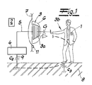
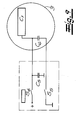
- Fig. 1 is a keyless actuation and / or Locking device shown in its basic structure.
- This user-specific Disk 1 is from a motor vehicle Control unit 2 on the access authorization queried the person in question 3b.
- a bidirectional data exchange or dialog is running by electromagnetic means (i.e. wireless) between the user-specific data carrier 1 and the motor vehicle side Control unit 2 from. It is well known (cf. EP 0 218 251 B1 by way of example only) and not Subject of the present invention.
- a Trigger signal generator provided, which essentially has a capacitive sensor 3.
- This capacitive working sensor 3 has two electrodes, namely a sensor electrode or conductivity electrode 3a on the one hand and a hand or another of the conductivity electrode 3a approaching part 3b of the human Body or person 3b on the other hand. In this part 3b it is within the scope of the embodiment outstretched hand 3b of the operator concerned.
- the evaluation unit 4 is connected via a feed line 5 to the conductivity electrode 3a, which in turn is embedded in a handle or a handle 6.
- an associated motor vehicle 7 can be opened, of which only part of a motor vehicle door 7 is shown.
- a lock that locks the motor vehicle door 7 Prior to this, however, a lock that locks the motor vehicle door 7 must be unlocked, which takes place following the positive data query between the operator-specific data carrier 1 and the motor vehicle-side control unit 2.
- the aforementioned capacitances in the pF range are measured by the evaluation unit 4, which is designed as an electronic (microprocessor) circuit and is capacitively coupled to the ground potential or ground potential 8 within the scope of the exemplary embodiment.
- a connecting line 9 is used for this purpose.
- the operator is also capacitively coupled to the ground or earth potential 8, which is indicated by capacitors C 2 , C 3 indicated in each case in comparison to the capacitor C 1 formed by the electrodes 3 a, 3 b.
- the electrode 3a or conductivity electrode 3a may be as Grid or surface electrode and be designed by the operator have an applied dielectric for insulation. Shields are also conceivable to ensure that those located on the conductivity electrode 3a Loads from the motor vehicle or the motor vehicle door Form 7 away-facing field.
- the trigger signal described only as an example for the introduction of the previously discussed question / answer dialog as part of the access authorization check is used in a motor vehicle. You might as well the trigger signal generator is also easy to operate Light source, for opening a door, unlocking one Lock etc. can be used.
- the changes in capacitance associated with the approach of the hand 3b to the conductivity electrode 3a are determined as variations in the charging time and / or the discharging time of the sensor 3.
- the sensor 3 - in addition to the capacitor C 1 formed from the conductivity electrode 3a and the hand 3b - also has a reference capacitor C 4 (cf. FIGS. 2, 8 and 9).
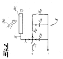
- the (external) parallel capacitor C 5 is charged and discharged at regular intervals. This is ensured by the evaluation unit 4 in connection with an indicated current source, the evaluation unit 4 closing a switch S 1 via a control line, which is an electronic switch, as part of the charging process shown in FIG. 2.
- a control line which is an electronic switch, as part of the charging process shown in FIG. 2.
- two further switches S 2 and S 3 are provided, which are open during the described charging process according to FIG. 2 and are also addressed by the evaluation unit 4 via control lines.
- the charging current flows primarily to the parallel capacitor C 5 and from there back to the ground or to the earth potential 8.
- the reference capacitor C 4 is not charged, so it keeps its charge Q which may be on it.
- the capacitor C 1 is equipped with a capacitance of almost 0, the charging current flows - as stated - mainly to the parallel capacitor C 5 .
- the capacitor C 1 assumes significant values or its capacitance changes from 0 to values in the pF range. Then a (slight) charging current flows on the one hand to the conductivity electrode 3a and on the other hand via the parallel capacitor C 5 back to the ground or to the ground potential 8.
- the charging process begins at a certain level of voltage or charge U, Q and ends after a threshold value U S , Q S has been exceeded.
- This threshold value U S , Q S of the voltage U at the reference capacitor C 4 or charge Q at the reference capacitor C 4 can be specified using the evaluation unit 4.
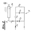
- the associated charging time T is detected by means of the evaluation unit 4 and then the switch S 2 is opened and the switch S 3 is closed, so that the short circuit caused thereby causes the reference capacitor C 4 discharges.
- a charge / discharge cycle with a duration L can be derived from this.
- the respective charging times T are dimensioned essentially the same and can be averaged, so that a reference time period T ref is available for the evaluation of approximations.
- the reference capacitor C 4 is therefore discharged at regular intervals, essentially in alternation with the charging processes of the parallel capacitor C 5 . This is because the parallel capacitor C 5 is alternately charged and discharged and transfers its charge to the reference capacitor C 4 when it is discharged.
- the reference capacitor C 4 is disconnected during charging of C 5 (and, if appropriate, C 1) of the parallel capacitor C 5, because the switch S is open then. 2
- This switch S 2 like the switches S 1 and S 3, is in each case an electronic transistor switch which, together with the evaluation unit 4 and the capacitors C 4 and C 5 and the conductivity electrode 3a, forms a compact electronic unit which, taken together can even be provided as a circuit.
- the recalibration is carried out at certain predetermined time intervals which are in the range from approx. 100 to 200 msec., In any case under one second.
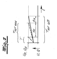
- the recalibration leads to the increased capacitance C 1 resulting in a reduced recharge time T ref , as shown in FIG. 6 in comparison to the original reference time period T ref old .
- the difference between T ref old and T ref new is measured at ⁇ x.
- the sensitivity of the sensor remains constant and takes into account environmental influences (rain, temperature) in particular.
- FIG. 7 compares the charging process taking into account the original charging time T ref old (solid) with the new charging time T ref new (dashed line) and this new charging time T ref new after the calibration of a charging time T when approaching faces a person 3b (dash-dotted). It can be seen that the sensitivity of the sensor 3, which can be determined by the amount .DELTA.t, does not change because only a shift in the reference time period T ref by the amount .DELTA.x has been carried out by the recalibration.
- the evaluation unit 4 and the parallel capacitor C 5 generally form a compact electronics unit.
- this is a microcomputer in which the parallel capacitor C 5 is integrated (cf. the dash-dotted representation in FIGS. 8 and 9).
- the switches S 1, S 2 and S 3 with the associated control lines can also be inserted in this microcomputer in the same way, so that only the conductivity electrode 3a and the reference capacitor C 4 remain as external components.
- switches S 4 to S 7 with associated control lines in connection with the parallel capacitor C 5 are also integrated in a compact electronic unit. This is indicated by the dash-dotted frame, which summarizes the evaluation unit 4 and the parallel capacitor C 5 . In contrast, only the reference capacitor C 4 and the capacitor C 1 remain.
- the cyclic charging of the parallel capacitor C 5 and its discharging by charge transfer to the reference capacitor C 4 is repeated until the reference capacitor C 4 is charged. This usually has a considerably higher capacitance than the parallel capacitor C 5 . Capacities for the reference capacitor C 4 of approximately 50 ⁇ F have proven to be favorable.
- the state of charge U in accordance with the reference capacitor C 4 can be measured in comparison to the predetermined threshold voltage U S , for example at the point indicated in FIG. 8. Two basic output values can be derived from the measured voltage U gem and the threshold voltage U S. If (6) U gem ⁇ U S . For example, the binary information "1" is generated by the evaluation unit 4 and output for further processing. The "1" represents the charged state of the reference capacitor C 4 . In the event that applies (7) U gem ⁇ U S . the reference capacitor C 4 is not (yet) charged, so that the charging processes described above must be continued. The binary information is "0".
Abstract
Description
Die Erfindung betrifft einen Auslösesignalgeber, beispielsweise zur Einleitung eines Frage-/Antwort-Dialogs im Rahmen einer Zugangsberechtigungsprüfung bei einem Kraftfahrzeug, mit einem kapazitiv arbeitenden Sensor, und mit einer Auswerteeinheit, wobei der Sensor Annäherungen und/oder Berührungen beispielsweise einer Person als zugehörige Kapazitätsänderungen erfasst und an die Auswerteeinheit weiterleitet.The invention relates to a trigger signal generator, for example to initiate a question / answer dialogue in the frame an access authorization check for a motor vehicle, with a capacitive sensor and with an evaluation unit, where the sensor approaches and / or touches for example a person as a related change in capacity recorded and forwarded to the evaluation unit.
Ein Auslösesignalgeber der eingangs beschriebenen Gestaltung wird im Rahmen der EP 0 954 098 A2 beschrieben. Bei dem bekannten Erkennungssystem ist ein Detektor als Auswerteeinheit zur Erfassung von Änderungen in der Kapazität eines Kondensators mit variabler und von der Nähe einer Person abhängiger Speicherfähigkeit vorgesehen. Mit Hilfe des Detektors werden Veränderungen dieses Kondensators erfasst, wobei sich der Kondensator aus einer kapazitiven Platte und beispielsweise einer Hand des zugehörigen Benutzers zusammensetzt, welche zusammengenommen einen Kondensator bilden, wenn sich die Hand der vorgenannten Platte nähert. Um nun die damit verbundenen Kapazitätsveränderungen feststellen zu können, ist die kapazitive Platte mit dem betreffenden Detektor verbunden, welcher eine Oszillatorschaltung aufweist, die ihrerseits mit einem Phasenvergleicher eines Phasenregelkreises verbunden ist.A trigger signal generator of the design described above is described in the context of EP 0 954 098 A2. at the known detection system is a detector as an evaluation unit to detect changes in capacity of a capacitor with variable and close to one Person dependent storage capacity provided. With help changes in this capacitor are detected by the detector, where the capacitor consists of a capacitive Plate and for example a hand of the associated user which is a capacitor form when the hand of the aforementioned plate approaches. Now about the associated changes in capacity The capacitive plate is included in the determination connected to the detector in question, which is an oscillator circuit has, in turn, with a phase comparator a phase locked loop is connected.
Das Ausgangssignal aus dem Phasenregelkreis wird in einem Komparator ausgewertet. Eine Kapazitätsänderung des Kondensators aus der kapazitiven Platte und der Hand bewirkt eine Änderung in der Frequenz des Oszillators, welcher ansonsten bei einer konstanten Frequenz arbeiten würde. Beispielsweise erhöht sich durch die Annäherung der Hand die Kapazität, was ein Absinken der Oszillator-Frequenz zur Folge hat.The output signal from the phase locked loop is in one Comparator evaluated. A change in capacitance of the capacitor from the capacitive plate and the hand creates one Change in the frequency of the oscillator, which otherwise would work at a constant frequency. For example when the hand approaches, the capacity increases, which results in a decrease in the oscillator frequency Has.
Diese Frequenzwandlung bewirkt eine Phasenänderung in dem Ausgangssignal des Oszillators, welches durch den Phasenvergleicher des Phasenregelkreises geleitet wird, um ein Störsignal oder Feedback-Signal des Phasenregelkreises zu erzeugen. Das Störsignal wird in den Komparator zum Vergleich mit einem vorgegebenen unteren Grenzpegel eingegeben. Wenn sich also die Hand dem Kondensator nähert, wird ein Störsignal von dem Phasenregelkreis aus erzeugt und - falls dieses Signal den unteren Grenzpegel überschreitet - wird der Komparator ein entsprechendes Ausgangssignal abgeben.This frequency conversion causes a phase change in the Output signal of the oscillator, which by the phase comparator of the phase-locked loop is passed to a Interference signal or feedback signal of the phase locked loop produce. The interference signal is in the comparator for comparison entered with a predetermined lower limit level. So when the hand approaches the capacitor, generates an interference signal from the phase locked loop and - if this signal exceeds the lower limit level - the comparator will emit a corresponding output signal.
Die beschriebene Vorgehensweise ist relativ aufwendig und letztlich an die zuverlässige Funktion des Oszillators gebunden.The procedure described is relatively complex and ultimately tied to the reliable functioning of the oscillator.
Daneben kennt man natürlich auch Auslösesignalgeber, welche einen Frage-/Antwort-Dialog im Rahmen einer Zugangsberechtigungsprüfung bei einem Kraftfahrzeug per manueller Schalterbetätigung auslösen (vgl. EP 0 218 251 B1).In addition, of course, there are also triggers which a question / answer dialog as part of an access authorization check in a motor vehicle by manual Trigger switch actuation (cf. EP 0 218 251 B1).
Der Erfindung liegt das technische Problem zugrunde, einen Auslösesignalgeber der eingangs beschriebenen Gestaltung so weiter zu entwickeln, dass bei einfachem und kostengünstigem Aufbau eine zuverlässige Annäherungssensierung gegeben ist.The invention is based on the technical problem Trigger signal generator of the design described above continue to develop that with simple and inexpensive Given a reliable proximity sensor is.
Zur Lösung dieser technischen Problemstellung schlägt die Erfindung bei einem gattungsgemäßen Auslösesignalgeber vor, dass die Kapazitätsänderungen als Variationen der Aufladezeit und/oder Entladezeit des Sensors ermittelt werden. - Üblicherweise verfügt der Sensor über eine Leitfähigkeitselektrode, die auf Annäherungen/Berührungen der Person im Sinne einer Kapazitätsänderung des aus der Leitfähigkeitselektrode und der Person gebildeten Kondensators reagiert. Zumeist hat eine entsprechende Annäherung oder Berührung beispielsweise einer Hand der Person zur Folge, dass sich die Kapazität des aus der Leitfähigkeitselektrode und der Hand gebildeten Kondensators erhöht.To solve this technical problem, the Invention with a generic trigger signal generator, that the capacity changes as variations in charging time and / or discharge time of the sensor can be determined. - The sensor usually has a conductivity electrode, which are based on approaches / contact of the person in the Meaning of a change in capacitance from the conductivity electrode and the person formed capacitor reacts. Mostly has a corresponding approach or touch for example a hand of the person that the capacity of the from the conductivity electrode and the Hand-formed capacitor increases.
Dieser Umstand lässt sich im Kern darauf zurückführen, dass
die Kapazität C des Kondensators reziproportional vom
Plattenabstand d abhängt, das heißt es gilt:
Folglich steigt die Kapazität bei geringer werdendem Plattenabstand d an.As a result, the capacity increases as the capacity decreases Plate spacing d.
Der Sensor weist bevorzugt wenigstens einen Referenzkondensator auf, welcher turnusmäßig aufgeladen wird, wobei die Aufladezeit mit Hilfe der Auswerteeinheit bestimmt wird und als Referenzzeitspanne für die Auswertung von Annäherungen oder Berührungen der Person zur Verfügung steht. Darüber hinaus lässt sich der Referenzkondensator turnusmäßig entladen. Daneben kann ein Parallelkondensator (zusätzlich zum aus der Leitfähigkeitselektrode und der Hand der Person ausgebildeten Kondensator) vorgesehen werden. Auch dieser Parallelkondensator wird turnusmäßig geladen und entladen. Der Parallelkondensator gibt seine Ladung beim Entladen an den Referenzkondensator ab, wobei der Referenzkondensator während des Ladevorganges des Parallelkondensators von einer zugehörigen Spannungsquelle abgekoppelt ist.The sensor preferably has at least one reference capacitor on which is regularly charged, the Charging time is determined using the evaluation unit and as a reference period for the evaluation of approximations or touching the person is available. About that In addition, the reference capacitor can be discharged at regular intervals. In addition, a parallel capacitor (in addition to the from the conductivity electrode and the hand of the person trained capacitor) are provided. This one too The parallel capacitor is charged and discharged at regular intervals. The parallel capacitor indicates its charge when discharging the reference capacitor, the reference capacitor during the charging process of the parallel capacitor from an associated voltage source is decoupled.
Die Erfindung wertet also im Kern Änderungen der Aufladezeit des Referenzkondensators aus, die durch Annäherungen der Hand an die Leitfähigkeitselektrode modifiziert werden. Dabei wird von der Erkenntnis ausgegangen, dass im Regelfall bei den beschriebenen Ladevorgängen einzig der Referenzkondensator zunehmend aufgeladen wird, weil insofern der parallel hierzu angeordnete Kondensator aus Leitfähigkeitselektrode und Hand mit einer Kapazität nahezu 0 ausgerüstet ist. Das lässt sich auf den großen Abstand der Hand von der Leitfähigkeitselektrode und die Beziehung (1) zurückführen.The invention thus essentially evaluates changes in the charging time of the reference capacitor by approximations be modified by hand on the conductivity electrode. It is based on the knowledge that, as a rule only the reference capacitor in the charging processes described is increasingly being charged because the capacitor made of a conductivity electrode arranged in parallel and hand equipped with a capacity almost 0 is. That can be explained by the large distance between the hands from the conductivity electrode and the relationship (1) traced.
Nähert sich jedoch die Hand der Leitfähigkeitselektrode, so
erhöht sich die Kapazität des Kondensators aus Leitfähigkeitselektrode
und Hand. Das hat zur Folge, dass sich beide
Kapazitäten (nämlich die des Referenzkondensators und des
Kondensators'aus Leitfähigkeitselektrode und Hand) zu einer
Gesamtkapazität oder Ersatzkapazität addieren, welche der
Summe der Einzelkapazitäten nach der Vorschrift

Es versteht sich, dass der Referenzkondensator als Präzisionspassivelement ausgeführt sein muss, um bauteilbedingte Kapazitätsschwankungen ausschalten zu können. Grundsätzlich ist es natürlich auch möglich, dass die Auswerteeinheit beispielsweise temperaturbedingte Kapazitätsschwankungen des Referenzkondensators kompensiert, so dass innerhalb der Auswerteeinheit eine mehr oder minder fixe Referenzzeitspanne (entsprechend der Aufladezeit des Referenzkondensators) zur Verfügung steht.It is understood that the reference capacitor as a precision passive element must be carried out in order to be component-related To be able to eliminate fluctuations in capacity. in principle it is of course also possible that the evaluation unit for example, temperature-related fluctuations in capacity of the reference capacitor compensated so that within the Evaluation unit a more or less fixed reference period (corresponding to the charging time of the reference capacitor) is available.
Das heißt, die jeweils ermittelte Aufladezeit für den Referenzkondensator führt zu einer Referenzzeitspanne, die sich bei gleichbleibenden Verhältnissen von Zyklus zu Zyklus nicht ändert. Gleiches gilt fraglos, wenn man an Stelle der Aufladezeit die Entladezeit auswertet.That is, the charging time determined for the reference capacitor leads to a reference period that is with constant conditions from cycle to cycle does not change. The same applies without question if you replace the Charging time evaluates the discharging time.
Dabei empfiehlt es sich, die Aufladezeit zur Ermittlung der Referenzzeitspanne über mehrere Zyklen (Aufladung und Entladung) zu mitteln und mit einer entsprechenden Fehlertoleranz auszurüsten. Diese Fehlertoleranz stellt sicher, dass nicht konstruktionsbedingte Schwankungen der Kapazität des Sensors als Annäherungen fehlinterpretiert werden. - Es versteht sich, dass naturgemäß nicht nur die Aufladezeit des Sensors zur Bildung der Referenzzeitspanne herangezogen werden kann. Sondern dies mag ebenso ergänzend oder alternativ für seine Entladezeit gelten.It is recommended that the charging time to determine the Reference period over several cycles (charging and discharging) to average and with a corresponding fault tolerance equip. This fault tolerance ensures that fluctuations in the capacity of the Sensors are misinterpreted as approximations. - It it goes without saying that naturally not only the charging time of the sensor is used to form the reference time period can be. But this may also be complementary or alternative apply to its discharge time.
Die Aufladezeit des Referenzkondensators wird als Zeitraum bis zum Erreichen eines bestimmten Schwellwertes der Ladung bzw. der Spannung des Referenzkondensators ermittelt. Das heißt, der Referenzkondensator wird beim Aufladen nicht vollständig, sondern vielmehr (nur) bis zu dem bestimmten Schwellwert aufgeladen. Gleiches gilt für den Entladevorgang. Entsprechende Vorgaben sind auch bei der Leitfähigkeitselektrode und dem Parallelkondensator zu berücksichtigen, so dass die Begriffe "Aufladen" und "Entladen" im Rahmen der Erfindung so zu verstehen sind, dass hiermit zeitlich begrenzte Lade-/Entladevorgänge gemeint sind, die meistens weder zum vollständigen Aufladen noch zum vollständigen Entladen führen. Grundsätzlich sind aber natürlich solche Vorgänge ebenfalls umfasst.The charging time of the reference capacitor is called the time period until a certain charge threshold is reached or the voltage of the reference capacitor. The means that the reference capacitor is not when charging completely, but rather (only) up to the certain Threshold charged. The same applies to the unloading process. Corresponding specifications also apply to the conductivity electrode and the parallel capacitor, so the terms "charging" and "discharging" in the frame the invention are to be understood in such a way that hereby temporally limited loading / unloading operations are meant that mostly neither for full charging nor for full Unload. Basically, however, are natural such operations also include.
Die jeweils am Referenzkondensator (inklusive ggf. parallelem Kondensator aus Leitfähigkeitselektrode und Hand) ermittelten Aufladezeiten bzw. Aufladezeitspannen werden von Zyklus zu Zyklus einander gegenübergestellt und mit der zuvor ermittelten Referenzzeitspanne verglichen. Überschreitet die Differenz zwischen diesen beiden Zeitspannen einen vorgegebenen Differenzwert, so wird dies als Annäherung bzw. Berührung der Leitfähigkeitselektrode durch die Person interpretiert. Selbstverständlich muss dieser Differenzwert außerhalb der zuvor angegebenen Fehlergrenze bei der Ermittlung der Referenzzeitspanne durch die stattgefundene Mittelung liegen. In der Regel beträgt der vorgenannte Differenzwert ein Vielfaches dieser Fehlergrenze, um Fehlinterpretationen von Kapazitätsvariationen als Annäherungen zu vermeiden.Each on the reference capacitor (including, if necessary, parallel Condenser from conductivity electrode and hand) determined Charging times or charging periods are from Cycle to cycle juxtaposed and with the previous one determined reference period compared. exceeds the difference between these two periods is one given difference value, this is called an approximation or touching the conductivity electrode by the person interpreted. Of course, this difference value outside the previously specified error limit in the determination the reference period by the one that has taken place Averaging. As a rule, the aforementioned difference value is a multiple of this margin of error to misinterpretation of capacity variations as approximations to avoid.
Solche Fehler können auch durch Umwelteinflüsse hervorgerufen
werden, die Kapazitätsänderungen bedingen. So führt
beispielsweise auf die Leitfähigkeitselektrode, welche zumeist
in einer Handhabe eines Kraftfahrzeuges angeordnet
ist, fallender Regen oder allgemein Luftfeuchtigkeit dazu,
dass die Kapazität des Sensors aus der Leitfähigkeitselektrode
und der Person bzw. Hand steigt. Das lässt sich
im Kern darauf zurückführen, dass der sich auf der Leitfähigkeitselektrode
(wenigstens zum Teil) niederschlagende
Flüssigkeitsfilm als Dielektrikum wirkt und demzufolge die
Kapazität C des betreffenden Kondensators im Vergleich zur
Kapazität C0 ohne Dielektrikum nach Maßgabe der Dielektrizitätszahl
εr steigert:
So kann die Dielektrizitätszahl εr von Wasser Werte von ca. 70 bis 80 je nach Temperatur des Wassers annehmen, wodurch sich die Kapazitätserhöhung gemäß (3) erklärt.The dielectric constant ε r of water can assume values of approx. 70 to 80 depending on the temperature of the water, which explains the increase in capacitance according to (3).
Derartige, durch Umwelteinflüsse bedingte, Kapazitätsänderungen des Sensors werden im Rahmen der Erfindung erfasst. Hierbei wird die Erkenntnis genutzt, dass solche Änderungen zumeist auf großen Zeitskalen von Minuten, wenn nicht sogar Stunden stattfinden und sich selten bis in den Sekundenbereich hinein auswirken. Da die hieraus resultierenden Kapazitätsänderungen eine Rekalibrierung der Referenzzeitspanne nach sich ziehen, genügt es folglich, diese Referenzeitspanne in Zeiträumen neu festzulegen, die unterhalb von 1 sec., bevorzugt unter 200 msec., liegen.Such changes in capacity due to environmental factors of the sensor are detected in the context of the invention. Here, the knowledge is used that such changes mostly on large time scales of minutes, if not Hours take place and rarely occur in the seconds range affect it. Because the resulting changes in capacity a recalibration of the reference period consequently, it is sufficient to refer to this period of time redefine in periods below 1 sec., Preferably less than 200 msec.
Sofern die Rekalibrierung in diesen Zeiträumen (weniger als 1 Sec. bzw. weniger als 200 msec.) durchgeführt wird, kann sichergestellt werden, dass innerhalb des betreffenden Zeitfensters Umwelteinflüsse praktisch keine Rolle spielen. Dagegen werden Annäherungen unmittelbar erfasst und als solche registriert, weil beispielsweise eine Hand den Ansprechabstand des Sensors in wenigen msec. erreicht.If the recalibration occurs during these periods (less than 1 sec or less than 200 msec.), can ensure that within that Time window environmental influences play practically no role. On the other hand, approximations are recorded immediately and as such registered because, for example, a hand the response distance of the sensor in a few msec. reached.
Selbstverständlich ist es auch denkbar, dass die beschriebene Rekalibrierung gleichsam aktiv unterstützt wird, indem (Außen-)Temperatur und -Feuchte gemessen werden. Wenn das Verhalten des Sensors zuvor labortechnisch in Abhängigkeit von diesen Parametern aufgenommen worden ist, lässt sich aus den ermittelten Daten auf die damit verbundenen Kapazitätsänderungen rückschließen und gleichsam aktiv - vorauseilend - eine Rekalibrierung vornehmen, ohne dass die zuvor beschriebenen Zeitfenster berücksichtigt werden müssten. Einfacher ist es jedoch, die Rekalibrierung in etwa alle 100 msec. durchzuführen, wobei dieser Zeitraum sicherstellt, dass Umwelteinflüsse innerhalb der betreffenden Zeitspanne als nicht existent bzw. konstant angesehen werden können. Denn diese wirken sich erst über Zeiträume von Sekunden, wenn nicht Minuten oder sogar Stunden aus.Of course, it is also conceivable that the described Recalibration is actively supported by (Outside) temperature and humidity can be measured. If that Behavior of the sensor previously dependent on laboratory technology has been absorbed by these parameters from the determined data on the associated changes in capacity conclude and as it were active - leading ahead - Recalibrate without the previous described time window would have to be taken into account. However, it is easier to recalibrate approximately all of them 100 msec. which period ensures that that environmental influences within the concerned Time period considered non-existent or constant can be. Because these only work over time from seconds, if not minutes, or even hours.
Im Ergebnis wird ein Auslösesignalgeber zur Verfügung gestellt, welcher insbesondere im Zusammenhang mit einer sogenannten "keyless entry"- oder auch einer "keyless go"-Abfrage bei einem Kraftfahrzeug eingesetzt wird. Grundsätzlich sind natürlich auch andere Einsatzgebiete denkbar. So lässt sich mit dem erfindungsgemäßen Auslösesignalgeber beispielsweise auch ein Lichtschalter (nicht unbedingt in einem Kraftfahrzeug) einschalten, eine Tür öffnen, ein Schloss entriegeln etc.. Immer stellt der vergleichsweise einfache Aufbau sicher, dass Annäherungen einer zugehörigen Person zuverlässig registriert werden, und zwar größtenteils unabhängig von Umwelteinflüssen wie Regen, wechselnden Temperaturen etc.. Das ermöglicht die in kurzen Zeitabständen immer wiederholte Rekalibrierungsroutine.As a result, a trigger signal generator is made available which in particular in connection with a so-called "keyless entry" - or a "keyless go" query is used in a motor vehicle. in principle other areas of application are of course also conceivable. So can with the trigger signal generator according to the invention for example a light switch (not necessarily in a motor vehicle) switch on, open a door, on Unlock the lock etc. Always the comparative simple construction sure that approximates an associated one Person reliably registered, for the most part regardless of environmental influences such as rain, changing Temperatures etc. This enables the in short time intervals repeated recalibration routine.
Im Folgenden wird die Erfindung anhand einer lediglich ein Ausführungsbeispiel darstellenden Zeichnung näher erläutert; es zeigen:
- Fig. 1
- den erfindungsgemäßen Auslösesignalgeber bei einer schlüssellosen Betätigungs- und/oder Schließeinrichtung an einem Kraftfahrzeug schematisch,
- Fig. 2
- den Auslösesignalgeber beim Aufladevorgang seiner Leitfähigkeitselektrode,
- Fig. 3
- den Gegenstand nach Fig. 2 beim Entladen der Leitfähigkeitselektrode und gleichzeitigen Aufladen des Referenzkondensators,
- Fig. 4
- die Spannung bzw. Ladung am Referenzkondensator gegenüber der Zeit, einmal im ursprünglichen Zustand (durchgezogen) und einmal bei Annäherung einer Hand (strichpunktiert),
- Fig. 5
- den Gegenstand nach Fig. 2 schematisch bei Änderung der Umwelteinflüsse (Regen),
- Fig. 6
- den Prozess der Rekalibrierung am Beispiel der Spannung und Ladung am Referenzkondensator gegenüber der Zeit,
- Fig. 7
- die Ergebnisse nach der Fig. 4, die Rekalibrierung gemäß Fig. 6 und schließlich den Aufladevorgang bei sich annähernder Hand, wobei die ursprüngliche Zeit zum Aufladen des Referenzkondensators durchgezogen dargestellt ist, der rekalibrierte Zeitverlauf gestrichelt und schließlich der rekalibrierte Zeitverlauf bei Annäherung der Hand strichpunktiert,
- Fig. 8
- eine abgewandelte Ausgestaltung des Auslösesignalgebers entsprechend den Fig. 2 und 3 und
- Fig. 9
- den Gegenstand nach Fig. 8, reduziert auf seine wesentlichen Bestandteile.
- Fig. 1
- the trigger signal generator according to the invention in a keyless actuation and / or locking device on a motor vehicle schematically,
- Fig. 2
- the trigger signal generator during the charging process of its conductivity electrode,
- Fig. 3
- 2 when discharging the conductivity electrode and simultaneously charging the reference capacitor,
- Fig. 4
- the voltage or charge on the reference capacitor versus time, once in the original state (solid) and once when one hand approaches (dash-dotted),
- Fig. 5
- 2 schematically when changing the environmental influences (rain),
- Fig. 6
- the process of recalibration using the example of voltage and charge on the reference capacitor versus time,
- Fig. 7
- 4, the recalibration according to FIG. 6 and finally the charging process when the hand is approaching, the original time for charging the reference capacitor being shown in solid lines, the recalibrated time curve in dashed lines and finally the recalibrated time curve when the hand approaches,
- Fig. 8
- a modified embodiment of the trigger signal generator according to FIGS. 2 and 3 and
- Fig. 9
- 8, reduced to its essential components.
In der Fig. 1 ist eine schlüssellose Betätigungs- und/oder
Schließeinrichtung in ihrem grundsätzlichen Aufbau dargestellt.
Man erkennt einen zutrittswilligen Bediener bzw.
eine Person 3b, welche(r) beispielsweise in einer Tasche
einen bedienerspezifischen Datenträger 1 trägt. Dieser bedienerspezifische
Datenträger 1 wird von einer kraftfahrzeugseitigen
Steuereinheit 2 auf die Zutrittsberechtigung
der betreffenden Person 3b hin abgefragt. Zu diesem Zweck
läuft zumeist ein bidirektionaler Datenaustausch bzw. Dialog
auf elektromagnetischem Weg (das heißt drahtlos) zwischen
dem bedienerspezifischen Datenträger 1 und der kraftfahrzeugseitigen
Steuereinheit 2 ab. Das ist allgemein bekannt
(vgl. nur beispielhaft die EP 0 218 251 B1) und nicht
Gegenstand der vorliegenden Erfindung.In Fig. 1 is a keyless actuation and / or
Locking device shown in its basic structure.
One recognizes an operator willing to access or
a
Um den vorerwähnten Datenaustausch zu initiieren, ist ein
Auslösesignalgeber vorgesehen, welcher im Wesentlichen
einen kapazitiv arbeitenden Sensor 3 aufweist. Dieser kapazitiv
arbeitende Sensor 3 verfügt über zwei Elektroden,
nämlich eine Sensorelektrode bzw. Leitfähigkeitselektrode
3a einerseits und eine Hand oder ein anderes sich der Leitfähigkeitselektrode
3a näherndes Teil 3b des menschlichen
Körpers bzw. der Person 3b andererseits. Bei diesem Teil 3b
handelt es sich im Rahmen des Ausführungsbeispiels um die
ausgestreckte Hand 3b des betreffenden Bedieners.To initiate the aforementioned data exchange, is a
Trigger signal generator provided, which essentially
has a
Die Leitfähigkeitselektrode 3a und die Hand 3b formen zusammengenommen
einen Kondensator C1 innerhalb des kapazitiv
arbeitenden Sensors 3. Dabei führt das Annähern der Hand 3b
und damit der zugehörigen Elektrode 3b in Richtung auf die
Leitfähigkeitselektrode 3a zu Kapazitätsänderungen des Sensors
3, welche an eine Auswerteeinheit 4 weitergeleitet
werden bzw. dort eine Auswertung erfahren. Die Auswerteeinheit
4 steht über eine Zuleitung 5 mit der Leitfähigkeitselektrode
3a in Verbindung, die ihrerseits in einen Handgriff
bzw. eine Handhabe 6 eingebettet ist. Mit Hilfe
dieses Handgriffes bzw. der Handhabe 6 lässt sich ein zugehöriges
Kraftfahrzeug 7 öffnen, von welchem nur ein Teil
einer Kraftfahrzeugtür 7 dargestellt ist. Zuvor muss jedoch
ein die Kraftfahrzeugtür 7 verriegelndes Schloss entriegelt
werden, was im Anschluss an die positive Datenabfrage zwischen
bedienerspezifischem Datenträger 1 und kraftfahrzeugseitiger
Steuereinheit 2 erfolgt. The
Die durch Annäherung der Hand 3b verursachten Kapazitätsänderungen
des Sensors 3 bzw. des Kondensators 3a, 3b bewegen
sich zumeist im pF-Bereich, wobei sich ein Ansprechabstand
von ca. 30 mm zwischen der Leitfähigkeitselektrode 3a und
der Hand 3b als vorteilhaft erwiesen hat.The capacity changes caused by the
Die vorerwähnten Kapazitäten im pF-Bereich werden von der
Auswerteeinheit 4 gemessen, die als elektronischer (Mikroprozessor-)Schaltkreis
ausgeführt ist und im Rahmen des
Ausführungsbeispiels kapazitiv an das Massepotential bzw.
Erdpotential 8 gekoppelt ist. Hierzu dient eine Verbindungsleitung
9. Auch die Bedienperson ist mit dem Masse-
bzw. Erdpotential 8 kapazitiv gekoppelt, was durch jeweils
angedeutete Kondensatoren C2, C3 im Vergleich zum Kondensator
C1, gebildet durch die Elektroden 3a, 3b, angedeutet
ist.The aforementioned capacitances in the pF range are measured by the
Auf diese Weise entsteht ein geschlossener elektrischer
Stromkreis, so dass Kapazitätsänderungen des Kondensators
C1 problemlos mit Hilfe der Auswerteeinheit 4 erfasst
werden können. Hierzu dienen periodische Lade-/Entladevorgänge
des betreffenden Kondensators 3a, 3b bzw. der Leitfähigkeitselektrode
3a, welche von der Auswerteeinheit 4
initiiert, überwacht und ausgewertet werden, wie nachfolgend
im Detail erläutert wird.In this way, a closed electrical circuit is created, so that changes in capacitance of the capacitor C 1 can be detected with the aid of the
Die Elektrode 3a bzw. Leitfähigkeitselektrode 3a mag als
Gitter- oder Flächenelektrode ausgeführt sein und bedienerseitig
ein aufgelegtes Dielektrikum zur Isolierung aufweisen.
Zusätzlich sind Abschirmungen denkbar, die gewährleisten,
dass die auf der Leitfähigkeitselektrode 3a befindlichen
Ladungen ein vom Kraftfahrzeug bzw. der Kraftfahrzeugtür
7 weg gerichtetes Feld formen. - Es sollte betont
werden, dass der beschriebene Auslösesignalgeber nur
beispielhaft zur Einleitung des zuvor erläuterten Frage/Antwort-Dialogs
im Rahmen der Zugangsberechtigungsprüfung
bei einem Kraftfahrzeug eingesetzt wird. Genauso gut könnte
der Auslösesignalgeber auch einfach zur Betätigung einer
Lichtquelle, zur Öffnung einer Tür, Entriegelung eines
Schlosses etc. Verwendung finden.The
Erfindungsgemäß werden die mit Hilfe der Annäherung der
Hand 3b an die Leitfähigkeitselektrode 3a verbundenen Kapazitätsänderungen
als Variationen der Aufladezeit und/oder
der Entladezeit des Sensors 3 ermittelt. Zu diesem Zweck
verfügt der Sensor 3 - neben dem aus der Leitfähigkeitselektrode
3a und der Hand 3b gebildeten Kondensator C1 -
noch über einen Referenzkondensator C4 (vgl. Fig. 2, 8 und
9). Zu dem Kondensator C1 tritt ferner ein zumeist externer
Parallelkondensator C5 hinzu, wobei sich die Gesamtkapazität
wegen der Gleichung (2) zu Cges = C1 + C5 bemisst.According to the invention, the changes in capacitance associated with the approach of the
Der (externe) Parallelkondensator C5 wird turnusmäßig geladen
und entladen. Hierfür sorgt die Auswerteeinheit 4 in
Verbindung mit einer angedeuteten Stromquelle, wobei die
Auswerteeinheit 4 im Rahmen des in Fig. 2 dargestellten
Ladevorganges einen Schalter S1 über eine Steuerleitung
schließt, bei dem es sich um einen elektronischen Schalter
handelt. Neben diesem Schalter S1 sind zwei weitere Schalter
S2 und S3 vorgesehen, die bei dem beschriebenen Ladevorgang
gemäß Fig. 2 geöffnet sind und ebenfalls über
Steuerleitungen von der Auswerteeinheit 4 angesprochen werden.The (external) parallel capacitor C 5 is charged and discharged at regular intervals. This is ensured by the
Dadurch fließt der Ladestrom primär zum Parallelkondensator
C5 und von dort aus wieder zurück zur Masse bzw. zum Erdpotential
8. Bei diesem Vorgang wird der Referenzkondensator
C4 nicht geladen, behält also seine ggf. auf ihm befindliche
Ladung Q. Da im Normalfall der Kondensator C1 mit
einer Kapazität von nahezu 0 ausgerüstet ist, fließt der
Ladestrom - wie ausgeführt - hauptsächlich zum Parallelkondensator
C5. Nähert sich jedoch die Hand 3b der Leitfähigkeitselektrode
3a, so nimmt der Kondensator C1 nennenswerte
Werte an bzw. ändert sich seine Kapazität von 0 auf Werte
im pF-Bereich. Dann fließt auch ein (geringfügiger) Ladestrom
einerseits zu der Leitfähigkeitselektrode 3a und
andererseits über den Parallelkondensator C5 wieder zurück
zur Masse bzw. zum Erdpotential 8.As a result, the charging current flows primarily to the parallel capacitor C 5 and from there back to the ground or to the
Im Anschluss an diesen Ladevorgang des Parallelkondensators C5 (bzw. zusätzlich des Kondensators C1) wird der Schalter S1 geöffnet und der den Schaltkreis zwischen Parallelkondensator C5 und dem Referenzkondensator C4 verbindendes Schalter S2 geschlossen (vgl. Fig. 3). Der Schalter S3 bleibt geöffnet. Das hat zur Folge, dass die Ladung des Parallelkondensators C5 (und gegebenenfalls des Kondensators C1) nunmehr auf den Referenzkondensator C4 transferiert wird. Die beiden Kondensatoren C1 und C5 entladen sich also zugunsten einer Aufladung des Referenzkondensators C4. Damit einhergehend steigen Spannung U und Ladung Q am Referenzkondensator C4 entsprechend der durchgezogenen Linie nach Fig. 4. Tatsächlich folgt dieser Ladevorgang einer Exponentialkurve, weshalb die lineare Darstellung in den Fig. 4, 6 und 7 in Wirklichkeit nicht die Spannung und die Ladung am Referenzkondensator C4 repräsentiert, sondern vielmehr den natürlichen Logarithmus dieser Werte.Following this charging process of the parallel capacitor C 5 (or additionally the capacitor C 1 ), the switch S 1 is opened and the switch S 2 connecting the circuit between the parallel capacitor C 5 and the reference capacitor C 4 is closed (cf. FIG. 3). The switch S 3 remains open. As a result, the charge of the parallel capacitor C 5 (and possibly the capacitor C 1 ) is now transferred to the reference capacitor C 4 . The two capacitors C 1 and C 5 therefore discharge in favor of charging the reference capacitor C 4 . Along with this, voltage U and charge Q at reference capacitor C 4 rise in accordance with the solid line according to FIG. 4. In fact, this charging process follows an exponential curve, which is why the linear representation in FIGS. 4, 6 and 7 does not actually show the voltage and the charge on Reference capacitor C 4 represents, but rather the natural log of these values.
Man erkennt, dass der Ladevorgang bei einem bestimmten
Niveau der Spannung bzw. Ladung U,Q beginnt und nach
Überschreiten eines Schwellwertes US, QS endet. Dieser
Schwellwert US, QS der Spannung U am Referenzkondensator C4
bzw. Ladung Q am Referenzkondensator C4 kann mit Hilfe der
Auswerteeinheit 4 vorgegeben werden. Sobald die betreffende
Schwellspannung US (oder die Schwellladung QS) erreicht
worden ist, wird die zugehörige Aufladezeit T mittels der
Auswerteeinheit 4 erfasst und wird anschließend der
Schalter S2 geöffnet und der Schalter S3 geschlossen, so
dass der dadurch bewirkte Kurzschluss den Referenzkondensator
C4 entlädt. Das geschieht jedoch nicht vollständig,
sondern nur so lange, bis der Referenzkondensator C4 erneut
geladen wird, wie die Fig. 4 andeutet. Daraus lässt sich
ein Lade-/Entladezyklus mit einer Dauer L ableiten.It can be seen that the charging process begins at a certain level of voltage or charge U, Q and ends after a threshold value U S , Q S has been exceeded. This threshold value U S , Q S of the voltage U at the reference capacitor C 4 or charge Q at the reference capacitor C 4 can be specified using the
Sofern sich keine Hand 3b der Leitfähigkeitselektrode 3a
nähert und demzufolge die Kapazität C1 konstant in etwa 0
ist, sind die jeweiligen Aufladezeiten T im Wesentlichen
gleich bemessen und lassen sich mitteln, so dass eine
Referenzzeitspanne Tref für die Auswertung von Annäherungen
zur Verfügung steht. Der Referenzkondensator C4 wird also
turnusmäßig entladen, und zwar im Wesentlichen im Wechsel
mit Aufladevorgängen des Parallelkondensators C5. Denn der
Parallelkondensator C5 wird wechselweise, ebenfalls aufgeladen
und entladen und gibt seine Ladung beim Entladen an
den Referenzkondensator C4 ab.If no
Der Referenzkondensator C4 ist während des Ladevorganges
von C5 (und gegebenenfalls C1) von dem Parallelkondensator
C5 abgekoppelt, weil dann der Schalter S2 geöffnet ist. Bei
diesem Schalter S2 handelt es sich ebenso wie bei den
Schaltern S1 und S3 jeweils um einen elektronischen Transistorschalter,
welcher zusammen mit der Auswerteeinheit 4
und den Kondensatoren C4 und C5 sowie der Leitfähigkeitselektrode
3a eine kompakte elektronische Baueinheit bildet,
die zusammengenommen sogar als ein Schaltkreis zur Verfügung
gestellt werden kann.The reference capacitor C 4 is disconnected during charging of C 5 (and, if appropriate, C 1) of the parallel capacitor C 5, because the switch S is open then. 2 This switch S 2 , like the switches S 1 and S 3, is in each case an electronic transistor switch which, together with the
Nähert sich nun jedoch die Hand 3b der Leitfähigkeitselektrode
3a, so steigt wegen der Beziehung (1) die Kapazität
C1 und auch die Gesamtkapazität C1 + C5 an. Das hat
zur Folge, dass auch die auf beiden Kondensatoren C1 und C5
gespeicherte Ladung größer wird. Diese vergrößerte Ladung
auf den Kondensatoren C1 und C5 steht dann natürlich auch
beim Ladevorgang für den Referenzkondensator C4 im Rahmen
der Fig. 3 zur Verfügung. Das führt dazu, dass der
Ladevorgang des Referenzkondensators C4 insgesamt schneller
vonstatten geht, weil der fließende Strom wegen
Sobald der ermittelte Differenzwert zwischen den jeweiligen Aufradezeitspannen Tref und T, das heißt die Zeitspanne Δt, einen vorgegebenen Differenzwert überschreitet, lässt sich dies als Annäherung interpretieren. Im Rahmen der Erfindung wird eine solche Annäherung erst dann gemeldet, wenn Δt ein Vielfaches der zuvor bereits angesprochenen Fehlervariation bei der Bestimmung der gemittelten Referenzzeitspanne Tref beträgt.As soon as the determined difference value between the respective charging time periods T ref and T, that is to say the time period Δt, exceeds a predetermined difference value, this can be interpreted as an approximation. Within the scope of the invention, such an approximation is only reported when Δt is a multiple of the error variation already mentioned when determining the averaged reference time period T ref .
Durch Umwelteinflüsse können sich Kapazitätsänderungen des
Sensors 3 ergeben, die mit Bezug zu den Fig. 5, 6 und 7
näher erläutert werden, und zwar am Beispiel von Regen oder
Nebel als Umwelteinfluss. Derartige Änderungen der Messbedingungen
rufen Kapazitätsänderungen des Sensors 3 bzw. des
zugehörigen Kondensators 3a, 3b bzw. C1 nach Maßgabe der
Vorschrift (3) hervor. Tatsächlich führt nämlich ein
Feuchtigkeitsfilm zumeist zu einer Kapazitätserhöhung von
C1 (vgl. Fig. 5).Environmental influences can result in changes in the capacitance of the
Diesen durch Umwelteinflüsse bedingten Kapazitätsänderungen wird durch eine Rekalibrierung der Referenzzeitspanne Tref begegnet. Die Rekalibrierung wird in bestimmten vorgegebenen Zeitabständen vorgenommen, die im Bereich von ca. 100 bis 200 msec., auf jeden Fall unter einer Sekunde, betragen.These changes in capacity due to environmental influences are countered by recalibrating the reference time period T ref . The recalibration is carried out at certain predetermined time intervals which are in the range from approx. 100 to 200 msec., In any case under one second.
Die Rekalibrierung führt dazu, dass die erhöhte Kapazität C1 eine verringerte Aufladezeit Tref neu nach sich zieht, wie dies in Fig. 6 im Vergleich zur ursprünglichen Referenzzeitspanne Tref alt dargestellt ist. Die Differenz zwischen Tref alt und Tref neu bemisst sich zu Δx. Das hat zur Folge, dass die Empfindlichkeit des Sensors gleichbleibend ist und insbesondere Umwelteinflüssen (Regen, Temperatur) Rechnung trägt.The recalibration leads to the increased capacitance C 1 resulting in a reduced recharge time T ref , as shown in FIG. 6 in comparison to the original reference time period T ref old . The difference between T ref old and T ref new is measured at Δx. As a result, the sensitivity of the sensor remains constant and takes into account environmental influences (rain, temperature) in particular.
Das kommt in der Fig. 7 zum Ausdruck, welche den Ladevorgang
unter Berücksichtigung der ursprünglichen Ladezeit
Tref alt (durchgezogen) mit der neuen Ladezeit Tref neu
(gestrichelt) vergleicht und diese neue Aufladezeit Tref
neu nach der Rakalibrierung einer Aufladezeit T bei Annäherung
einer Person 3b gegenüberstellt (strichpunktiert).
Man erkennt, dass sich die Empfindlichkeit des Sensors 3,
welche am Betrag Δt festgemacht werden kann, nicht ändert,
weil durch die Rekalibrierung lediglich eine Verschiebung
der Referenzzeitspanne Tref um den Betrag Δx vorgenommen
worden ist.This is shown in FIG. 7, which compares the charging process taking into account the original charging time T ref old (solid) with the new charging time T ref new (dashed line) and this new charging time T ref new after the calibration of a charging time T when approaching faces a
Die Auswerteeinheit 4 und der Parallelkondensator C5 bilden
in der Regel eine kompakte Elektronikeinheit. Tatsächlich
handelt es sich hierbei im Rahmen des Ausführungsbeispiels
zusammengenommen um einen Mikrocomputer, in welchen der
Parallelkondensator C5 integriert ist (vgl. die strichpunktierte
Darstellung in den Fig. 8 und 9). Selbstverständlich
können in diesen Mikrocomputer in gleicher
Weise auch die Schalter S1, S2 und S3 mit den zugehörigen
Steuerleitungen eingefügt sein, so dass als externe
Bauteile lediglich die Leitfähigkeitselektrode 3a und der
Referenzkondensator C4 verbleiben. Das führt zu einer
kostengünstigen Bauweise, wobei vom Erfindungsgedanken
natürlich auch Variationen dergestalt umfasst werden, dass
ebenso die beiden vorgenannten Bauteile 3a, C4 insgesamt in
einen elektronischen Schaltkreis integriert werden.The
Auch bei der Variante nach den Fig. 8 und 9 sind dortige
Schalter S4 bis S7 mit zugehörigen Steuerleitungen in
Verbindung mit dem Parallelkondensator C5 in eine kompakte
Elektronikeinheit integriert. Das ist durch die strichpunktierte
Umrahmung angedeutet, welche die Auswerteeinheit
4 und den Parallelkondensator C5 zusammenfasst. Demgegenüber
verbleiben lediglich der Referenzkondensator C4 und
der Kondensator C1.8 and 9, switches S 4 to S 7 with associated control lines in connection with the parallel capacitor C 5 are also integrated in a compact electronic unit. This is indicated by the dash-dotted frame, which summarizes the
Die Funktionsweise dieser Variante ist wie folgt. Im Ausgangszustand addiert sich die Gesamtkapazität der jeweils parallel geschalteten Kondensatoren C1, C4 und C5 zu Null. Zum Aufladen des Parallelkondensators C5 wird der Schalter S4 geschlossen, während die übrigen Schalter S5 bis S7 geöffnet sind. Im Anschluss daran wird C5 mit einer Kapazität von ca. 10 bis 20 pF, insbesondere 15 pF, aufgeladen. Darauf folgend werden die Schalter S4 und S7 geschlossen bzw. auf Masse geschaltet, während die Schalter S5 und S6 geöffnet bleiben. Dadurch wird die auf dem Parallelkondensator C5 befindliche Ladung auf den Referenzkondensator C4 übertragen. Gleichzeitig entlädt sich der Parallelkondensator C5. This variant works as follows. In the initial state, the total capacitance of the capacitors C 1 , C 4 and C 5 connected in parallel adds up to zero. To charge the parallel capacitor C 5 , the switch S 4 is closed, while the other switches S 5 to S 7 are open. Then C 5 is charged with a capacitance of approx. 10 to 20 pF, in particular 15 pF. Following this, switches S 4 and S 7 are closed or switched to ground, while switches S 5 and S 6 remain open. As a result, the charge located on the parallel capacitor C 5 is transferred to the reference capacitor C 4 . At the same time, the parallel capacitor C 5 discharges.
Das zyklische Aufladen des Parallelkondensators C5 und
dessen Entladen durch Ladungsübertragung auf den Referenzkondensator
C4 wird so lange wiederholt, bis der Referenzkondensator
C4 aufgeladen ist. Dieser verfügt zumeist über
eine erheblich höhere Kapazität als der Parallelkondensator
C5. Es haben sich Kapazitäten für den Referenzkondensator
C4 von in etwa 50 µF als günstig erwiesen. Der Ladezustand
Ugem des Referenzkondensators C4 lässt sich im Vergleich zu
der vorgegebenen Schwellspannung US messen, und zwar beispielsweise
an der in Fig. 8 angedeuteten Stelle. Aus der
gemessenen Spannung Ugem und der Schwellspannung US können
zwei grundsätzliche Ausgangswerte abgeleitet werden. Falls
Nun können diese wiederholten Ladevorgänge von der Auswerteeinheit
4 jeweils erfasst und gezählt werden. Sobald
sich die binäre Information "1" einstellt, wird der Zähl-Vorgang
abgebrochen und die Anzahl der Zyklen NZ1 festgehalten.
Im Anschluss daran wird der Referenzkondensator
C4 entladen, in dem die Schalter S4, S5 und S6 geöffnet
werden, während der geschlossene Schalter S7 für den gewünschten
Ladungstransport sorgt.These repeated charging processes can now be recorded and counted by the
Sobald der aus der Hand 3b und der Leitfähigkeitselektrode
3a gebildete Kondensator 3a, 3b bzw. C1 nennenswerte Kapazitäten
erreicht (weil sich ein Bediener genähert hat)
ändert sich die Anzahl der erforderlichen Zyklen, bis nun
der Referenzkondensator C4 inklusive parallel geschaltetem
Kondensator C1 in der Summe aufgeladen ist (vgl. die
Beziehung (2)). Denn die Parallelschaltung des Referenzkondensators
C4 und des Kondensators C1 führt zu einer
addierten Kapazität. Diese erfordert nun eine erhöhte
Anzahl von Zyklen NZ2, bis der jeweilige Ladungstransfer
des Parallelkondensators C5 die vorgenannte Gesamtkapazität
aufgeladen hat, d. h. bis die Schwellspannung US erreicht
worden ist.As soon as the
Daraus resultiert die neue Zahl an gemessenen Zyklen NZ2.
Sobald die Differenz
Falls sich diese Änderungen der Zyklenzahl ΔNZ auf längeren Zeitskalen abspielen, kann auf diese Weise eine Rekalibrierung vorgenommen werden. Denn Änderungen der Umwelteinflüsse schlagen sich unmittelbar in einer abweichenden Zykluszahl NZ nieder, die als neuer Referenzwert NZ1 für nachfolgende Auswertungen von Annäherungen zur Verfügung steht. Das heißt, hier wird ähnlich gearbeitet wie zuvor erläutert. Umwelteinflüsse führen zu einer neuen Zykluszahl Nzneu bzw. NZ1, die gegenüber der ursprünglichen Zykluszahl Nzalt um den Betrag Δx abweicht. Nzneu wird nun mit NZ1 gleichgesetzt, um ΔNZ entsprechend der Beziehung (8) bestimmen zu können.If these changes in the number of cycles ΔN Z occur on longer time scales, a recalibration can be carried out in this way. This is because changes in environmental influences are directly reflected in a different number of cycles N Z , which is available as a new reference value N Z1 for subsequent evaluations of approximations. This means that the work is carried out in a similar way as previously explained. Environmental influences lead to a new cycle number N new or . N Z1 , which differs from the original number of cycles N zalt by the amount Δx. N zneu is now equated with N Z1 in order to be able to determine ΔN Z according to the relationship (8).
Claims (10)
Applications Claiming Priority (4)
| Application Number | Priority Date | Filing Date | Title |
|---|---|---|---|
| DE10207167 | 2002-02-20 | ||
| DE10207167 | 2002-02-20 | ||
| DE10215591.7A DE10215591B4 (en) | 2002-02-20 | 2002-04-10 | Activating transducer |
| DE10215591 | 2002-04-10 |
Publications (2)
| Publication Number | Publication Date |
|---|---|
| EP1339025A1 true EP1339025A1 (en) | 2003-08-27 |
| EP1339025B1 EP1339025B1 (en) | 2007-01-03 |
Family
ID=27664559
Family Applications (1)
| Application Number | Title | Priority Date | Filing Date |
|---|---|---|---|
| EP03003730A Expired - Lifetime EP1339025B1 (en) | 2002-02-20 | 2003-02-19 | Vehicle with release trigger |
Country Status (3)
| Country | Link |
|---|---|
| EP (1) | EP1339025B1 (en) |
| AT (1) | ATE350730T1 (en) |
| DE (1) | DE50306147D1 (en) |
Cited By (20)
| Publication number | Priority date | Publication date | Assignee | Title |
|---|---|---|---|---|
| WO2005108175A1 (en) * | 2004-04-30 | 2005-11-17 | Huf Hülsbeck & Fürst Gmbh & Co. Kg | Device for operating electrical or electromechanical entry or access systems on or in a vehicle |
| EP1619633A3 (en) * | 2004-07-22 | 2006-06-14 | Hella KGaA Hueck & Co. | Control Method for locking or unlocking doors in a motor vehicle |
| EP1686543A1 (en) * | 2005-01-28 | 2006-08-02 | Aisin Seiki Kabushiki Kaisha | Capacitance detection apparatus |
| WO2007012613A1 (en) * | 2005-07-26 | 2007-02-01 | Huf Hülsbeck & Fürst Gmbh & Co. Kg | Sensor arrangement for a motor-vehicle locking device and an associated method |
| DE102006053572B3 (en) * | 2006-11-14 | 2008-07-03 | Kiekert Ag | Sensor for protecting e.g. person against jam in opening locked by e.g. sliding door of vehicle, has conductive reference potential layer electrically isolated from reflective layer and provided on side opposite to electrode |
| EP2243906A2 (en) | 2009-04-22 | 2010-10-27 | Huf Hülsbeck & Fürst GmbH & Co. KG | Sensor electronics in a motor vehicle door handle |
| EP1583236B1 (en) * | 2004-03-30 | 2012-05-02 | Aisin Seiki Kabushiki Kaisha | Capacitance change detection device |
| CN102539935A (en) * | 2010-10-14 | 2012-07-04 | E.G.O.电气设备制造股份有限公司 | Method and apparatus for determining a capacitance and/or change in capacitance of a capacitive sensor element |
| DE102011053314A1 (en) | 2011-09-06 | 2013-03-07 | Huf Hülsbeck & Fürst Gmbh & Co. Kg | Capacitive sensor arrangement |
| DE102012100960A1 (en) * | 2012-02-06 | 2013-08-08 | Huf Hülsbeck & Fürst Gmbh & Co. Kg | Method for operating a capacitive sensor arrangement on a motor vehicle and associated device |
| EP2711488A2 (en) | 2012-09-25 | 2014-03-26 | Huf Hülsbeck & Fürst GmbH & Co. KG | Motor vehicle door handle with sensor electronics |
| WO2014068008A1 (en) * | 2012-10-30 | 2014-05-08 | Digades Gmbh Digitales Und Analoges Schaltungsdesign | Sensor system for detecting the approach of persons and objects, method for operating the sensor system and use thereof |
| DE102013102469A1 (en) | 2013-03-12 | 2014-10-02 | Huf Hülsbeck & Fürst Gmbh & Co. Kg | Capacitive sensor arrangement with shield electrode |
| CN104137419A (en) * | 2012-03-21 | 2014-11-05 | 胡夫·许尔斯贝克和福斯特有限及两合公司 | Capacitive sensor arrangement for switching a door opening in a motor vehicle and associated method |
| US9081032B2 (en) | 2010-10-22 | 2015-07-14 | Huf Huelsbeck & Fuerst Gmbh & Co. Kg | Capacitive sensor arrangement for switching a door opening on a motor vehicle |
| DE102015122086A1 (en) | 2015-12-17 | 2017-06-22 | Huf Hülsbeck & Fürst Gmbh & Co. Kg | Vehicle door handle with pressure switch |
| US9829346B2 (en) | 2013-09-12 | 2017-11-28 | Huf Huelsbeck & Fuerst Gmbh & Co. Kg | Operating device for motor vehicles |
| US9945171B2 (en) | 2015-02-11 | 2018-04-17 | Huf Huelsbeck & Fuerst Gmbh & Co. Kg | Sensor assembly for a motor vehicle |
| EP2824002B1 (en) | 2010-11-04 | 2021-05-12 | Huf Hülsbeck & Fürst GmbH & Co. KG | Method for opening or closing a motor vehicle |
| DE102004048329B4 (en) | 2004-10-05 | 2022-08-11 | Volkswagen Ag | Method for operating an outdoor sensor and corresponding device |
Families Citing this family (12)
| Publication number | Priority date | Publication date | Assignee | Title |
|---|---|---|---|---|
| DE102009031824A1 (en) | 2009-07-03 | 2011-01-05 | Huf Hülsbeck & Fürst Gmbh & Co. Kg | Capacitive sensor arrangement with a sensor electrode, a shield electrode and a background electrode |
| DE102010027505B4 (en) | 2009-07-17 | 2024-04-18 | Huf Hülsbeck & Fürst Gmbh & Co. Kg | Sensor device and method for actuating a movable part of a motor vehicle, with a sensor device |
| DE102009059202A1 (en) | 2009-07-20 | 2011-02-03 | Huf Hülsbeck & Fürst Gmbh & Co. Kg | sensor module |
| DE102010002559A1 (en) | 2010-03-03 | 2011-09-08 | Huf Hülsbeck & Fürst Gmbh & Co. Kg | Capacitive sensor arrangement for detection of e.g. door opening of motor car, has sensing electrode arrangements formed of elongated segments which are arranged in longitudinal direction to enable different capacitive detections |
| DE102011053897A1 (en) | 2011-09-23 | 2013-03-28 | Huf Hülsbeck & Fürst Gmbh & Co. Kg | Sensor arrangement for use in motor car to detect approximation of object, has target electrode extending axially outside sensing electrode in partial section of less sensitivity, and control circuit to adjust potential of target electrode |
| DE102012102060A1 (en) | 2012-03-12 | 2013-09-12 | Huf Hülsbeck & Fürst Gmbh & Co. Kg | Capacitive sensor arrangement for detection of e.g. deked kicks at motor car, has evaluating device designed such that time sequence between signal change is evaluated during examination of detection operation of device |
| DE102012104916A1 (en) | 2012-06-06 | 2013-12-12 | Huf Hülsbeck & Fürst Gmbh & Co. Kg | Capacitive sensor arrangement for switching a door opening on a motor vehicle |
| DE102012104915A1 (en) | 2012-06-06 | 2013-12-12 | Huf Hülsbeck & Fürst Gmbh & Co. Kg | Capacitive sensor arrangement for switching a door opening on a motor vehicle |
| DE102012105363A1 (en) | 2012-06-20 | 2013-12-24 | Huf Hülsbeck & Fürst Gmbh & Co. Kg | Sensor arrangement for detecting movement gestures of operator at motor car, has control and evaluating device actuating time-shifted sensing electrode portion subsections and separately determining capacitance of subsections |
| DE102012110436A1 (en) | 2012-10-31 | 2014-04-30 | Huf Hülsbeck & Fürst Gmbh & Co. Kg | Electronic sensor unit for detecting a contactless actuation of a door or flap on a motor vehicle |
| DE102013105539A1 (en) | 2013-05-29 | 2014-12-04 | Huf Hülsbeck & Fürst Gmbh & Co. Kg | Electronic sensor unit for detecting a contactless actuation of a door or flap on a motor vehicle |
| EP3057234B1 (en) | 2015-02-11 | 2018-11-21 | Huf Hülsbeck & Fürst GmbH & Co. KG | Sensor assembly for a motor vehicle |
Citations (3)
| Publication number | Priority date | Publication date | Assignee | Title |
|---|---|---|---|---|
| DE19701899A1 (en) * | 1996-01-21 | 1997-10-30 | Ifm Electronic Gmbh | Capacitance or capacitance variation detection circuit |
| DE19620059A1 (en) * | 1996-05-20 | 1997-11-27 | Ifm Electronic Gmbh | Switching circuit for unlocking of car door lock |
| US5730165A (en) * | 1995-12-26 | 1998-03-24 | Philipp; Harald | Time domain capacitive field detector |
-
2003
- 2003-02-19 AT AT03003730T patent/ATE350730T1/en not_active IP Right Cessation
- 2003-02-19 DE DE50306147T patent/DE50306147D1/en not_active Expired - Lifetime
- 2003-02-19 EP EP03003730A patent/EP1339025B1/en not_active Expired - Lifetime
Patent Citations (3)
| Publication number | Priority date | Publication date | Assignee | Title |
|---|---|---|---|---|
| US5730165A (en) * | 1995-12-26 | 1998-03-24 | Philipp; Harald | Time domain capacitive field detector |
| DE19701899A1 (en) * | 1996-01-21 | 1997-10-30 | Ifm Electronic Gmbh | Capacitance or capacitance variation detection circuit |
| DE19620059A1 (en) * | 1996-05-20 | 1997-11-27 | Ifm Electronic Gmbh | Switching circuit for unlocking of car door lock |
Cited By (33)
| Publication number | Priority date | Publication date | Assignee | Title |
|---|---|---|---|---|
| EP1583236B1 (en) * | 2004-03-30 | 2012-05-02 | Aisin Seiki Kabushiki Kaisha | Capacitance change detection device |
| CN100450838C (en) * | 2004-04-30 | 2009-01-14 | 胡夫休尔斯贝克及福尔斯特公司 | Device for operating electrical or electromechanical entry or access systems on or in a vehicle |
| WO2005108175A1 (en) * | 2004-04-30 | 2005-11-17 | Huf Hülsbeck & Fürst Gmbh & Co. Kg | Device for operating electrical or electromechanical entry or access systems on or in a vehicle |
| KR101089854B1 (en) * | 2004-04-30 | 2011-12-05 | 후프 휠스벡 운트 퓌르스트 게엠베하 운트 콤파니 카게 | Device for operating electrical or electromechanical entry or access systems on or in a vehicle |
| EP1619633A3 (en) * | 2004-07-22 | 2006-06-14 | Hella KGaA Hueck & Co. | Control Method for locking or unlocking doors in a motor vehicle |
| DE102004048329B4 (en) | 2004-10-05 | 2022-08-11 | Volkswagen Ag | Method for operating an outdoor sensor and corresponding device |
| EP1686543A1 (en) * | 2005-01-28 | 2006-08-02 | Aisin Seiki Kabushiki Kaisha | Capacitance detection apparatus |
| US7245131B2 (en) | 2005-01-28 | 2007-07-17 | Aisin Seiki Kabushiki Kaisha | Capacitance detection apparatus |
| WO2007012613A1 (en) * | 2005-07-26 | 2007-02-01 | Huf Hülsbeck & Fürst Gmbh & Co. Kg | Sensor arrangement for a motor-vehicle locking device and an associated method |
| US7654147B2 (en) * | 2005-07-26 | 2010-02-02 | Huf Hulsbeck & Furst Gmbh & C. Kg | Sensor arrangement for a motor-vehicle locking device and an associated method |
| CN101233287B (en) * | 2005-07-26 | 2011-01-26 | 胡夫·许尔斯贝克和福斯特有限及两合公司 | Sensor arrangement for a motor-vehicle locking device and an associated method |
| DE102006053572B3 (en) * | 2006-11-14 | 2008-07-03 | Kiekert Ag | Sensor for protecting e.g. person against jam in opening locked by e.g. sliding door of vehicle, has conductive reference potential layer electrically isolated from reflective layer and provided on side opposite to electrode |
| US8482303B2 (en) | 2009-04-22 | 2013-07-09 | Huf Hulsbeck & Furst Gmbh & Co. Kg | Sensor electronics in a vehicle door handle |
| DE102009002566A1 (en) | 2009-04-22 | 2010-10-28 | Huf Hülsbeck & Fürst Gmbh & Co. Kg | Sensor electronics in a motor vehicle door handle |
| EP2243906A2 (en) | 2009-04-22 | 2010-10-27 | Huf Hülsbeck & Fürst GmbH & Co. KG | Sensor electronics in a motor vehicle door handle |
| US8854063B2 (en) | 2010-10-14 | 2014-10-07 | E.G.O. Elektro-Gerätebau GmbH | Method and apparatus for determining a capacitance and/or change in capacitance of a capacitive sensor element |
| EP2442447A3 (en) * | 2010-10-14 | 2014-03-05 | E.G.O. Elektro-Gerätebau GmbH | Method and device for determining a capacity and/or a change in capacity of a capacitive sensor element |
| CN102539935A (en) * | 2010-10-14 | 2012-07-04 | E.G.O.电气设备制造股份有限公司 | Method and apparatus for determining a capacitance and/or change in capacitance of a capacitive sensor element |
| US9081032B2 (en) | 2010-10-22 | 2015-07-14 | Huf Huelsbeck & Fuerst Gmbh & Co. Kg | Capacitive sensor arrangement for switching a door opening on a motor vehicle |
| EP2824002B1 (en) | 2010-11-04 | 2021-05-12 | Huf Hülsbeck & Fürst GmbH & Co. KG | Method for opening or closing a motor vehicle |
| DE102011053314A1 (en) | 2011-09-06 | 2013-03-07 | Huf Hülsbeck & Fürst Gmbh & Co. Kg | Capacitive sensor arrangement |
| EP2568605A1 (en) | 2011-09-06 | 2013-03-13 | Huf Hülsbeck & Fürst GmbH & Co. KG | Capacitative sensor assembly |
| US9464921B2 (en) | 2012-02-06 | 2016-10-11 | Huf Huelsbeck & Fuerst Gmbh & Co. Kg | Method for the operation of a capacitive sensor array on a motor vehicle and associated device |
| DE102012100960A1 (en) * | 2012-02-06 | 2013-08-08 | Huf Hülsbeck & Fürst Gmbh & Co. Kg | Method for operating a capacitive sensor arrangement on a motor vehicle and associated device |
| CN104137419B (en) * | 2012-03-21 | 2019-01-11 | 胡夫·许尔斯贝克和福斯特有限及两合公司 | Control the capacitance sensing device assembly and corresponding operating method of automobile door open |
| CN104137419A (en) * | 2012-03-21 | 2014-11-05 | 胡夫·许尔斯贝克和福斯特有限及两合公司 | Capacitive sensor arrangement for switching a door opening in a motor vehicle and associated method |
| DE102012109034A1 (en) | 2012-09-25 | 2014-03-27 | Huf Hülsbeck & Fürst Gmbh & Co. Kg | Motor vehicle door handle with sensor electronics |
| EP2711488A2 (en) | 2012-09-25 | 2014-03-26 | Huf Hülsbeck & Fürst GmbH & Co. KG | Motor vehicle door handle with sensor electronics |
| WO2014068008A1 (en) * | 2012-10-30 | 2014-05-08 | Digades Gmbh Digitales Und Analoges Schaltungsdesign | Sensor system for detecting the approach of persons and objects, method for operating the sensor system and use thereof |
| DE102013102469A1 (en) | 2013-03-12 | 2014-10-02 | Huf Hülsbeck & Fürst Gmbh & Co. Kg | Capacitive sensor arrangement with shield electrode |
| US9829346B2 (en) | 2013-09-12 | 2017-11-28 | Huf Huelsbeck & Fuerst Gmbh & Co. Kg | Operating device for motor vehicles |
| US9945171B2 (en) | 2015-02-11 | 2018-04-17 | Huf Huelsbeck & Fuerst Gmbh & Co. Kg | Sensor assembly for a motor vehicle |
| DE102015122086A1 (en) | 2015-12-17 | 2017-06-22 | Huf Hülsbeck & Fürst Gmbh & Co. Kg | Vehicle door handle with pressure switch |
Also Published As
| Publication number | Publication date |
|---|---|
| ATE350730T1 (en) | 2007-01-15 |
| DE50306147D1 (en) | 2007-02-15 |
| EP1339025B1 (en) | 2007-01-03 |
Similar Documents
| Publication | Publication Date | Title |
|---|---|---|
| EP1339025A1 (en) | Release trigger | |
| EP1505734B1 (en) | Capacitive proximity switch | |
| EP1235190B1 (en) | Keyless actuating and/or locking device | |
| EP2795798B1 (en) | Device and method for evaluating the capacitance of a sensor electrode of a proximity sensor | |
| EP1910631B1 (en) | Sensor arrangement for a motor-vehicle locking device and an associated method | |
| DE102011010620B4 (en) | Method for measuring a capacitance | |
| EP1450489B1 (en) | Release trigger | |
| EP1341306B1 (en) | Circuit for a capacitive sensor element | |
| EP2828973B1 (en) | Capacitive sensor arrangement for switching a door opening in a motor vehicle and associated method | |
| DE102006029120A1 (en) | Circuit arrangement for detection of capacitance or change of capacitance of capacitive circuit or element, has controlling unit, has constant current generator which is downstream to exit of mono-stable flip flop circuit | |
| EP1966892A1 (en) | Sensor arrangement for detecting the pressing of a user body part on a sensor surface | |
| WO2013189752A1 (en) | Capacitive proximity sensor for a motor vehicle | |
| DE4242230A1 (en) | Sensor arrangement for detecting lateral impact on vehicle - contains capacitive sensor element with one deformable plate and deformable dielectric | |
| EP1770653B1 (en) | Triggering device for vehicles | |
| EP1103432A1 (en) | Vehicle door lock system | |
| WO2000018012A1 (en) | Dead-man switch | |
| EP0820391B1 (en) | Arrangement for triggering a personal protection system | |
| DE10215591B4 (en) | Activating transducer | |
| DE102008014516A1 (en) | Vehicle door-lock device for locking and unlocking a vehicle door secured by an electronic access-authorization system and fitted with a door-handle on an outer side has an unlocking sensor and a forward-motion sensor to detect a hand | |
| CH700376A2 (en) | Capacitive sensor and method for capacitive sensing an object distance. | |
| EP2915145A1 (en) | Sensor system for detecting the approach of persons and objects, method for operating the sensor system and use thereof | |
| EP2943630B1 (en) | Capacitive proximity sensor arrangement on a door of a motor vehicle for detecting an approximately horizontal approaching movement of an operator's hand | |
| DE10339753B4 (en) | Method for measuring a physical quantity and circuit arrangement for detecting the capacitance or a capacitance change of a capacitive circuit or component | |
| DE10108354A1 (en) | Keyless activation or locking arrangement, especially for motor vehicle use, where an authentication request is sent by onboard controller when a driver approaches within a certain range, based on a capacitive sensor arrangement | |
| DE10149343A1 (en) | Keyless actuation/locking device, especially for vehicles, has sensor for initiating data interrogation between data medium, control unit activated/deactivated depending on vehicle status |
Legal Events
| Date | Code | Title | Description |
|---|---|---|---|
| PUAI | Public reference made under article 153(3) epc to a published international application that has entered the european phase |
Free format text: ORIGINAL CODE: 0009012 |
|
| AK | Designated contracting states |
Designated state(s): AT BE BG CH CY CZ DE DK EE ES FI FR GB GR HU IE IT LI LU MC NL PT SE SI SK TR |
|
| AX | Request for extension of the european patent |
Extension state: AL LT LV MK RO |
|
| 17P | Request for examination filed |
Effective date: 20040219 |
|
| AKX | Designation fees paid |
Designated state(s): AT BE BG CH CY CZ DE DK EE ES FI FR GB GR HU IE IT LI LU MC NL PT SE SI SK TR |
|
| 17Q | First examination report despatched |
Effective date: 20041019 |
|
| GRAP | Despatch of communication of intention to grant a patent |
Free format text: ORIGINAL CODE: EPIDOSNIGR1 |
|
| RTI1 | Title (correction) |
Free format text: VEHICLE WITH RELEASE TRIGGER |
|
| GRAS | Grant fee paid |
Free format text: ORIGINAL CODE: EPIDOSNIGR3 |
|
| GRAA | (expected) grant |
Free format text: ORIGINAL CODE: 0009210 |
|
| AK | Designated contracting states |
Kind code of ref document: B1 Designated state(s): AT BE BG CH CY CZ DE DK EE ES FI FR GB GR HU IE IT LI LU MC NL PT SE SI SK TR |
|
| PG25 | Lapsed in a contracting state [announced via postgrant information from national office to epo] |
Ref country code: IE Free format text: LAPSE BECAUSE OF FAILURE TO SUBMIT A TRANSLATION OF THE DESCRIPTION OR TO PAY THE FEE WITHIN THE PRESCRIBED TIME-LIMIT Effective date: 20070103 Ref country code: FI Free format text: LAPSE BECAUSE OF FAILURE TO SUBMIT A TRANSLATION OF THE DESCRIPTION OR TO PAY THE FEE WITHIN THE PRESCRIBED TIME-LIMIT Effective date: 20070103 Ref country code: NL Free format text: LAPSE BECAUSE OF FAILURE TO SUBMIT A TRANSLATION OF THE DESCRIPTION OR TO PAY THE FEE WITHIN THE PRESCRIBED TIME-LIMIT Effective date: 20070103 Ref country code: DK Free format text: LAPSE BECAUSE OF FAILURE TO SUBMIT A TRANSLATION OF THE DESCRIPTION OR TO PAY THE FEE WITHIN THE PRESCRIBED TIME-LIMIT Effective date: 20070103 Ref country code: SI Free format text: LAPSE BECAUSE OF FAILURE TO SUBMIT A TRANSLATION OF THE DESCRIPTION OR TO PAY THE FEE WITHIN THE PRESCRIBED TIME-LIMIT Effective date: 20070103 |
|
| REG | Reference to a national code |
Ref country code: GB Ref legal event code: FG4D Free format text: NOT ENGLISH |
|
| REF | Corresponds to: |
Ref document number: 50306147 Country of ref document: DE Date of ref document: 20070215 Kind code of ref document: P |
|
| REG | Reference to a national code |
Ref country code: IE Ref legal event code: FG4D Free format text: LANGUAGE OF EP DOCUMENT: GERMAN |
|
| PG25 | Lapsed in a contracting state [announced via postgrant information from national office to epo] |
Ref country code: LI Free format text: LAPSE BECAUSE OF NON-PAYMENT OF DUE FEES Effective date: 20070228 Ref country code: MC Free format text: LAPSE BECAUSE OF NON-PAYMENT OF DUE FEES Effective date: 20070228 Ref country code: CH Free format text: LAPSE BECAUSE OF NON-PAYMENT OF DUE FEES Effective date: 20070228 |
|
| PG25 | Lapsed in a contracting state [announced via postgrant information from national office to epo] |
Ref country code: SE Free format text: LAPSE BECAUSE OF FAILURE TO SUBMIT A TRANSLATION OF THE DESCRIPTION OR TO PAY THE FEE WITHIN THE PRESCRIBED TIME-LIMIT Effective date: 20070403 |
|
| PG25 | Lapsed in a contracting state [announced via postgrant information from national office to epo] |
Ref country code: BG Free format text: LAPSE BECAUSE OF EXPIRATION OF PROTECTION Effective date: 20070404 |
|
| PG25 | Lapsed in a contracting state [announced via postgrant information from national office to epo] |
Ref country code: ES Free format text: LAPSE BECAUSE OF FAILURE TO SUBMIT A TRANSLATION OF THE DESCRIPTION OR TO PAY THE FEE WITHIN THE PRESCRIBED TIME-LIMIT Effective date: 20070414 |
|
| PG25 | Lapsed in a contracting state [announced via postgrant information from national office to epo] |
Ref country code: PT Free format text: LAPSE BECAUSE OF FAILURE TO SUBMIT A TRANSLATION OF THE DESCRIPTION OR TO PAY THE FEE WITHIN THE PRESCRIBED TIME-LIMIT Effective date: 20070604 |
|
| NLV1 | Nl: lapsed or annulled due to failure to fulfill the requirements of art. 29p and 29m of the patents act | ||
| ET | Fr: translation filed | ||
| GBV | Gb: ep patent (uk) treated as always having been void in accordance with gb section 77(7)/1977 [no translation filed] |
Effective date: 20070103 |
|
| REG | Reference to a national code |
Ref country code: IE Ref legal event code: FD4D |
|
| PLBI | Opposition filed |
Free format text: ORIGINAL CODE: 0009260 |
|
| REG | Reference to a national code |
Ref country code: CH Ref legal event code: PL |
|
| PLAX | Notice of opposition and request to file observation + time limit sent |
Free format text: ORIGINAL CODE: EPIDOSNOBS2 |
|
| 26 | Opposition filed |
Opponent name: IFM ELECTRONIC GMBH Effective date: 20071004 |
|
| PG25 | Lapsed in a contracting state [announced via postgrant information from national office to epo] |
Ref country code: SK Free format text: LAPSE BECAUSE OF FAILURE TO SUBMIT A TRANSLATION OF THE DESCRIPTION OR TO PAY THE FEE WITHIN THE PRESCRIBED TIME-LIMIT Effective date: 20070103 Ref country code: GB Free format text: LAPSE BECAUSE OF FAILURE TO SUBMIT A TRANSLATION OF THE DESCRIPTION OR TO PAY THE FEE WITHIN THE PRESCRIBED TIME-LIMIT Effective date: 20070103 |
|
| BERE | Be: lapsed |
Owner name: KIEKERT A.G. Effective date: 20070228 |
|
| PG25 | Lapsed in a contracting state [announced via postgrant information from national office to epo] |
Ref country code: CZ Free format text: LAPSE BECAUSE OF FAILURE TO SUBMIT A TRANSLATION OF THE DESCRIPTION OR TO PAY THE FEE WITHIN THE PRESCRIBED TIME-LIMIT Effective date: 20070103 Ref country code: BE Free format text: LAPSE BECAUSE OF NON-PAYMENT OF DUE FEES Effective date: 20070228 |
|
| PLBB | Reply of patent proprietor to notice(s) of opposition received |
Free format text: ORIGINAL CODE: EPIDOSNOBS3 |
|
| PG25 | Lapsed in a contracting state [announced via postgrant information from national office to epo] |
Ref country code: IT Free format text: LAPSE BECAUSE OF FAILURE TO SUBMIT A TRANSLATION OF THE DESCRIPTION OR TO PAY THE FEE WITHIN THE PRESCRIBED TIME-LIMIT Effective date: 20070103 Ref country code: GR Free format text: LAPSE BECAUSE OF FAILURE TO SUBMIT A TRANSLATION OF THE DESCRIPTION OR TO PAY THE FEE WITHIN THE PRESCRIBED TIME-LIMIT Effective date: 20070404 |
|
| PG25 | Lapsed in a contracting state [announced via postgrant information from national office to epo] |
Ref country code: AT Free format text: LAPSE BECAUSE OF NON-PAYMENT OF DUE FEES Effective date: 20070219 |
|
| PLBP | Opposition withdrawn |
Free format text: ORIGINAL CODE: 0009264 |
|
| PLBD | Termination of opposition procedure: decision despatched |
Free format text: ORIGINAL CODE: EPIDOSNOPC1 |
|
| RAP2 | Party data changed (patent owner data changed or rights of a patent transferred) |
Owner name: HUF ELECTRONICS GMBH |
|
| PLAB | Opposition data, opponent's data or that of the opponent's representative modified |
Free format text: ORIGINAL CODE: 0009299OPPO |
|
| PG25 | Lapsed in a contracting state [announced via postgrant information from national office to epo] |
Ref country code: EE Free format text: LAPSE BECAUSE OF FAILURE TO SUBMIT A TRANSLATION OF THE DESCRIPTION OR TO PAY THE FEE WITHIN THE PRESCRIBED TIME-LIMIT Effective date: 20070103 |
|
| PLBM | Termination of opposition procedure: date of legal effect published |
Free format text: ORIGINAL CODE: 0009276 |
|
| STAA | Information on the status of an ep patent application or granted ep patent |
Free format text: STATUS: OPPOSITION PROCEDURE CLOSED |
|
| 27C | Opposition proceedings terminated |
Effective date: 20080921 |
|
| PG25 | Lapsed in a contracting state [announced via postgrant information from national office to epo] |
Ref country code: CY Free format text: LAPSE BECAUSE OF FAILURE TO SUBMIT A TRANSLATION OF THE DESCRIPTION OR TO PAY THE FEE WITHIN THE PRESCRIBED TIME-LIMIT Effective date: 20070103 |
|
| PG25 | Lapsed in a contracting state [announced via postgrant information from national office to epo] |
Ref country code: LU Free format text: LAPSE BECAUSE OF NON-PAYMENT OF DUE FEES Effective date: 20070219 |
|
| PG25 | Lapsed in a contracting state [announced via postgrant information from national office to epo] |
Ref country code: TR Free format text: LAPSE BECAUSE OF FAILURE TO SUBMIT A TRANSLATION OF THE DESCRIPTION OR TO PAY THE FEE WITHIN THE PRESCRIBED TIME-LIMIT Effective date: 20070103 Ref country code: HU Free format text: LAPSE BECAUSE OF FAILURE TO SUBMIT A TRANSLATION OF THE DESCRIPTION OR TO PAY THE FEE WITHIN THE PRESCRIBED TIME-LIMIT Effective date: 20070704 |
|
| REG | Reference to a national code |
Ref country code: FR Ref legal event code: TP |
|
| REG | Reference to a national code |
Ref country code: FR Ref legal event code: TP |
|
| PGFP | Annual fee paid to national office [announced via postgrant information from national office to epo] |
Ref country code: FR Payment date: 20110107 Year of fee payment: 9 |
|
| REG | Reference to a national code |
Ref country code: FR Ref legal event code: ST Effective date: 20121031 |
|
| PG25 | Lapsed in a contracting state [announced via postgrant information from national office to epo] |
Ref country code: FR Free format text: LAPSE BECAUSE OF NON-PAYMENT OF DUE FEES Effective date: 20120229 |
|
| PGFP | Annual fee paid to national office [announced via postgrant information from national office to epo] |
Ref country code: DE Payment date: 20210223 Year of fee payment: 19 |
|
| REG | Reference to a national code |
Ref country code: DE Ref legal event code: R119 Ref document number: 50306147 Country of ref document: DE |
|
| PG25 | Lapsed in a contracting state [announced via postgrant information from national office to epo] |
Ref country code: DE Free format text: LAPSE BECAUSE OF NON-PAYMENT OF DUE FEES Effective date: 20220901 |