EP1341316A2 - Remote control apparatus, electronic apparatus, and available-button indicating method - Google Patents
Remote control apparatus, electronic apparatus, and available-button indicating method Download PDFInfo
- Publication number
- EP1341316A2 EP1341316A2 EP03250842A EP03250842A EP1341316A2 EP 1341316 A2 EP1341316 A2 EP 1341316A2 EP 03250842 A EP03250842 A EP 03250842A EP 03250842 A EP03250842 A EP 03250842A EP 1341316 A2 EP1341316 A2 EP 1341316A2
- Authority
- EP
- European Patent Office
- Prior art keywords
- operation buttons
- available
- remote control
- control apparatus
- electronic apparatus
- Prior art date
- Legal status (The legal status is an assumption and is not a legal conclusion. Google has not performed a legal analysis and makes no representation as to the accuracy of the status listed.)
- Granted
Links
Images


Classifications
-
- H—ELECTRICITY
- H04—ELECTRIC COMMUNICATION TECHNIQUE
- H04B—TRANSMISSION
- H04B1/00—Details of transmission systems, not covered by a single one of groups H04B3/00 - H04B13/00; Details of transmission systems not characterised by the medium used for transmission
- H04B1/06—Receivers
- H04B1/16—Circuits
- H04B1/20—Circuits for coupling gramophone pick-up, recorder output, or microphone to receiver
- H04B1/202—Circuits for coupling gramophone pick-up, recorder output, or microphone to receiver by remote control
-
- H—ELECTRICITY
- H01—ELECTRIC ELEMENTS
- H01H—ELECTRIC SWITCHES; RELAYS; SELECTORS; EMERGENCY PROTECTIVE DEVICES
- H01H2219/00—Legends
- H01H2219/036—Light emitting elements
- H01H2219/039—Selective or different modes of illumination
Definitions
- the present invention relates to a remote control apparatus, portable communications terminal, and operation panel for remotely operating a multifunctional electronic apparatus. More particularly, it relates to a remote control apparatus, etc. with enhanced operability.
- remote control apparatuses for remotely operating such apparatuses are configured such that the number of operation buttons is increased, that two or more operational functions are assigned to a single operation button, or that operations are controlled hierarchically according to operating status of an electronic apparatus.
- a remote control apparatus for remotely operating an electronic apparatus provided with: a reception device which receives a signal indicating available operation buttons transmitted from the electronic apparatus; and an indication device which explicitly indicates (specifies) available operation buttons from among a plurality of operation buttons based on the received signal which indicates available operation buttons.
- buttons are indicated (specified) fromamongaplurality of operation buttons, the user can understand quickly and precisely what buttons are available. Thus, it is possible to achieve simpler operability.
- a remote control apparatus for remotely operating an electronic apparatus provided with: a plurality of operation buttons for remotely operating the electronic apparatus; a transmission device which transmits an operation signal to the electronic apparatus in accordance with any operation button pressed from among the operation buttons; a reception device which receives a signal indicating available operation buttons transmitted from the electronic apparatus after the operation signal is transmitted to the electronic apparatus; and an indication device which explicitly indicates available operation buttons from among said plurality of operation buttons based on the received signal which indicates the available operation buttons.
- buttons are indicated from among a plurality of operation buttons, the user can understand quickly and precisely what button to press next after pressing a first button. Thus, it is possible to achieve simpler operability.
- each of the operation buttons has an illumination capability, and the indication device illuminates the available operation buttons.
- each of the operation buttons has a vibration capability, and the indication device vibrates the available operation buttons.
- each of the operation buttons has an illumination capability and vibration capability, and the indication device both illuminates and vibrates the available operation buttons.
- buttons are both illuminated and vibrated.
- the user can understand available operation buttons through both visual and tactile senses.
- the user can understand more quickly and precisely what buttons are available.
- the indication device explicitly indicates the available operation buttons only if the reception device receives a signal which indicates the available operation buttons within a predetermined time after the operation button is pressed.
- the remote control apparatus may be a portable communications terminal such as a portable telephone, PHS (Personal Handy-phone System), PDA (mobile terminal), or the like.
- a portable communications terminal such as a portable telephone, PHS (Personal Handy-phone System), PDA (mobile terminal), or the like.
- buttons are indicated from among a plurality of operation buttons on a portable communications terminal, the user can understand quickly and precisely what buttons are available. Thus, it is possible to achieve simpler operability.
- an electronic apparatus provided with: a selection device which selects available operation buttons on a remote control apparatus equipped with a plurality of operation buttons for remotely operating the electronic apparatus; and a transmission device which transmits a signal which indicates the selected available operation buttons to the remote control apparatus.
- the remote control apparatus can explicitly indicate the available operation buttons based on the signal.
- an electronic apparatus provided with: a reception device which receives an operation signal transmitted from a remote control apparatus equipped with a plurality of operation buttons for remotely operating an electronic apparatus; a selection device which selects available operation buttons on the remote control apparatus based on the received operation signal; and a transmission device which transmits a signal which indicates the selected available operation buttons to the remote control apparatus.
- the remote control apparatus can explicitly indicate the available operation buttons based on the signal.
- an electronic apparatus equipped with an operation panel which contains a plurality of operation buttons provided with: a recognition device which recognizes any operation button pressed from among the operation buttons; a selection device which selects available operation buttons from among the plurality of operation buttons based on results of the recognition; and an indication device which explicitly indicates the selected available operation buttons.
- buttons are indicated from among a plurality of operation buttons, the user can understand quickly and precisely what button to press next after pressing a first button. Thus, it is possible to achieve simpler operability.
- each of the operation buttons has an illumination capability; and the indication device illuminates the available operation buttons.
- each of the operation buttons has a vibration capability, and the indication device vibrates the available operation buttons.
- each of the operation buttons has an illumination capability and vibration capability, and the indication device both illuminates and vibrates the available operation buttons.
- buttons are both illuminated and vibrated.
- the user can understand available operation buttons through both visual and tactile senses.
- the user can understand more quickly and precisely what buttons are available.
- the operation panel is removably mounted on the electronic apparatus.
- an available-button indicating method for explicitly indicating, to the user, operation buttons available for use to remotely operate an electronic apparatus from among a plurality of operation buttons mounted on a remote control apparatus provided with: a step in which the electronic apparatus selects available operation buttons on the remote control apparatus; a step in which the electronic apparatus transmits a signal indicating the selected available operation buttons to the remote control apparatus; and a step in which the remote control apparatus indicates the available operation buttons from among said plurality of operation buttons based on the signal indicating the available operation buttons and transmitted from the electronic apparatus.
- buttons are indicated from among a plurality of operation buttons, the user can understand quickly and precisely what buttons are available. Thus, it is possible to achieve simpler operability.
- an available-button indicating method for explicitly indicating, to the user, operation buttons available for use to operate an electronic apparatus from among a plurality of operation buttons mounted on a remote control apparatus provided with: a step in which the remote control apparatus transmits an operation signal to the electronic apparatus in accordance with any operation button pressed from among said plurality of operation buttons on the remote control apparatus; a step in which the electronic apparatus selects available operation buttons on the remote control apparatus based on the operation signal transmitted from the remote control apparatus; a step in which the electronic apparatus transmits a signal indicating the selected available operation buttons to the remote control apparatus; and a step in which the remote control apparatus explicitly indicates the available operation buttons from among said plurality of operation buttons based on the signal indicating the available operation buttons and transmitted from the electronic apparatus.
- buttons are indicated from among a plurality of operation buttons, the user can understand quickly and precisely what button to press next after pressing a first button. Thus, it is possible to achieve simpler operability.
- a first embodiment concerns a case in which signals are exchanged between the audio apparatus described above and a remote control apparatus according to the present invention.
- FIG. 1 is a diagram showing an exemplary schematic inner configuration of an audio apparatus according to the first embodiment.
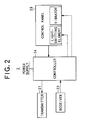
- FIG. 2 is a diagram showing an exemplary schematic inner configuration of a remote control apparatus (hereinafter referred to as a "remote controller") according to the first embodiment.
- FIG. 3 is a diagram showing a plurality of operation buttons mounted on a control panel of the remote controller 2.
- the audio apparatus 1 is provided with a transmitter 11 which transmits signals to a remote controller 2 according to instructions from a controller 19; a receiver 12 which serves as a reception device for receiving operation signals from the remote control 2; a CD player 13 which reads content such as music from a CD and outputs it as a reproduced signal; an MD player 14 which reads content such as music from an MD and outputs it as a reproduced signal; a tuner 15 which receives broadcast waves inputted via an antenna, detects them, and outputs them as a reproduced signal; a speaker 16 which outputs the reproduced signals as sound waves; a display (e.g., liquid crystal display) 17 which displays information from the controller 19; a display processor (microcomputer for display) 18 which has a display driver, etc. and carries out processes for displaying the above information on the display 17; and the controller 19 which controls all the components described above.
- a display e.g., liquid crystal display
- a display processor microcomputer for display
- the transmitter 11 as a transmission device has an infrared-emitting element and the like and transmits a signal indicated by the controller 19--for example, a signal which indicates available operation buttons described infrared pulse waves using an infrared band.
- the receiver 12 has an infrared-emitting element and the like. It receives infrared pulse waves of an operation signal transmitted from the remote controller 2 and supplies the operation signal to the controller 19 after photoelectric conversion.
- the CD player 13 and MD player 14 rotationally drive an CD or MD, read music from the CD or MD, and output it as a reproduced signal to the speaker 16, under drive control from the controller 19. Also, the CD player 13 and MD player 14 supplies management information (disc title, the titles and number of musical pieces, playback time, and other information) known as TOC (Table Of Content) and stored in the CD and MD, respectively, to the controller 19.
- management information disc title, the titles and number of musical pieces, playback time, and other information
- TOC Table Of Content
- the tuner 15 detects broadcast waves (RF signal) by tuning to the frequency of a broadcasting channel indicated by the controller 19 and outputs them as a reproduced signal to the speaker 16.
- the source--the CD player 13, MD player 14, or tuner 15--from which a reproduced signal should be output to the speaker 16 is determined by the controller 19.
- the controller 19 has a CPU (Central Processing Unit) with arithmetic capabilities, a working RAM, a ROM, a nonvolatile memory, etc.
- the controller 19 switches among the CD player 13, MD player 14, and tuner 15 to output reproduced signals based on an operation signal received by the receiver 12. Specifically, if an operation signal instructing playback is received by the remote controller 2, the controller 19 drives and controls the CD player 13 to make it output a reproduced signal.
- a CPU Central Processing Unit
- the controller 19 Based on the operation signal, the controller 19 displays the currently selected source (broadcasting channel in the case of the tuner) and its operational state (e.g., Playing CD) as well as TOC information supplied from the CD player 13 or MD player 14 on the display 17 via the display processor 18. This allows the user to see what source is currently selected, what is its operational state, and if a CD or MD is selected, what musical piece is being played back.
- the currently selected source broadcasting channel in the case of the tuner
- its operational state e.g., Playing CD
- the controller 19, which functions as a selection device according to the present invention, selects available operation buttons on the remote controller 2 and outputs a signal indicating them to the transmitter 11. For example, when an operation signal instructing playback (described later) is received, the controller 19 selects operation buttons which are needed to be operated during CD playback, such as FF (Fast Forward), Rewind, Stop, and Pause buttons (described later), as available operation buttons based on the operation signal. If CD is selected but stopped (e.g., when the audio apparatus is just powered on), the controller 19 selects Left and Right buttons (described later) as available operation buttons and outputs a signal indicating them to the transmitter 11, even in the absence of an operation signal from the remote controller 2, so that musical pieces recorded on the CD can be selected.
- operation buttons which are needed to be operated during CD playback such as FF (Fast Forward), Rewind, Stop, and Pause buttons (described later)
- FF Fast Forward
- Stop Stop buttons
- the remote controller 2 is provided with a transmitter 21 which serves as a transmission device for transmitting operation signals to the audio apparatus 1, a receiver 22 which serves as a reception device for receiving a signal indicating available operation buttons from the audio apparatus 1, a control panel 23 equipped with a plurality of operation buttons for remotely operating the audio apparatus 1, and a controller 24 which controls all the components described above.
- the transmitter 21 has an infrared-emitting element. When any operation button on the control panel 23 is pressed, the transmitter 21 transmits an operation signal which corresponds to the operation button as infrared pulse waves using an infrared band at the instruction of the controller 24. For example, if a music selection button is pressed, a corresponding operation signal is transmitted as infrared pulse waves.
- the receiver 22 has an infrared-emitting element and the like. It receives infrared pulse waves of a signal indicating available operation buttons transmitted from the audio apparatus 1 and supplies the controller 24 with a signal indicating the available operation buttons after photoelectric conversion.
- the control panel 23 contains the following operation buttons: a Source button 231 for transmitting an operation signal which gives an instruction to start source switching, Up button 232 and Down button 233 for transmitting an operation signal which gives an instruction to select a source, Left button 234 and Right button 235 for transmitting an operation signal which gives an instruction to select a musical piece recorded on a CD or MD, Enter button 236 for transmitting an operation signal which gives an instruction to decide on the source or musical piece selected with buttons 232 to 235 above, Play button 237 for transmitting an operation signal which gives an instruction to play back the musical piece selected and decided on, FF (Fast Forward) button 238 for transmitting an operation signal which gives a fast forward instruction for the music being played back, Rewind button 239 for transmitting an operation signal which gives a rewind instruction for the music being played back, Stop button 240 for transmitting an operation signal which gives an instruction to stop the music being played back, Pause button 241 for transmitting an operation signal which gives an instruction to pause the music being played back,
- each operation button is equipped with a light-emitting element (e.g., light-emitting diode) at a predetermined location on the back side and is illuminated by the light-emitting element.
- the illumination of the light-emitting elements is controlled by the controller 24.
- each operation button is equipped with a small vibrator at a predetermined location on the back side and vibrates by means of the vibrator.
- vibration-damping rubber is mounted (known vibration proof rubber may be used) in the place where each operation button contacts the remote controller 2. The vibration of the vibration absorbing elements is controlled by the controller 24.
- the controller 24 has a CPU (Central Processing Unit) with arithmetic capabilities, a working RAM, a ROM, a nonvolatile memory, etc.
- the controller 24 has a capability to detect a press of an operation button on the control panel 23 and outputs an operation signal corresponding to the pressed operation button to the transmitter 21.
- the controller 24 functions as an indication device according to the present invention and indicates available operation buttons from among the plurality of operation buttons based on a signal indicating the available operation buttons and received by the receiver 22. For example, if the available operation button is the Left button 234, the controller 24 explicitly indicates that the Left button 234 is available by illuminating it with the light-emitting element attached to it.
- the controller 24 explicitly indicates that the Left button 234 is available by vibrating it with the vibrator attached to it.
- FIG. 4 is a flowchart showing processes carried out by the CPU in the controller 19 of the audio apparatus 1 to select available operation buttons. These processes are carried out when a program for selecting available operation buttons is read from the ROM into the CPU which serves as a computer.
- the receiver 12 of the audio apparatus 1 Upon receiving infrared pulse waves of an operation signal fromthe remote controller 2, the receiver 12 of the audio apparatus 1 supplies the operation signal to the controller 19 after photoelectric conversion.
- the controller 19 receives the operation signal supplied from the receiver 12 (Step S1).
- the controller 19 selects available operation buttons based on the received operation signal (Step S2). For example, if an operation signal giving an instruction to start source switching is received, the controller 19 enters an operational state in which it waits for an instruction to select a source, and thus it rejects any other instruction such as an instruction to select a musical piece, instruction to play back a musical piece, instruction to select a broadcasting channel, or instruction to make a decision. Therefore, the controller 19 selects the Up button 232, Down button 233, and Enter button 236 as available operation buttons on the remote controller 2.
- the controller 19 If the tuner is selected as a source and an instruction to make a decision is received, the controller 19 enters an operational state in which it waits for an instruction to decide on a broadcasting channel, and thus it rejects, for example, an instruction to select a musical piece and an instruction to decide on a musical piece. Therefore, the controller 19 selects the channel selector buttons 242 and Source button 231 as available operation buttons on the remote controller 2.
- the controller 19 outputs a signal indicating the selected available operation buttons to the transmitter 11 (Step S3).
- the signal indicating the available operation buttons is transmitted as infrared pulse waves to the remote controller 2.
- FIG. 5 is a flowchart showing processes carried out by the CPU in the controller 24 of the remote controller 2 to indicate available operation buttons. These processes are carried out when a program for indicating available operation buttons is read from the ROM into the CPU which serves as a computer.
- the controller 24 sets a timer value (e.g., "10") (Step S11) .
- the operation signal outputted to the transmitter 21 is transmitted as infrared pulse waves to the audio apparatus 1.
- Step S12 If no press of an operation button is detected in Step S12, the controller 24 goes to Step S15, where it judges whether a signal indicating available operation buttons is received by the receiver 22. If no signal indicating available operation buttons is received, the controller 24 judges whether the timer value is "0" (which means a timeout) (Step S16). If the timer value is not “0,” the controller 24 decrements it by "1" (Step S17) and returns to Step S12. In this way, each time Step S17 is executed, the timer value is decremented by "1.” When the timer value reaches "0" in Step S16, the controller 24 gets out of the signal wait state (Step S18).
- Step S19 the controller 24 sets a timer value again in Step S14 after going through Step S13.
- Step S15 the controller 24 explicitly indicates the available operation buttons from among a plurality of operation buttons based on the received signal (Step S20) and sets a timer value again (Step S21) .
- the controller 24 indicates them explicitly by illuminating and vibrating them. Alternatively, it is possible to use either illumination or vibration.
- a restoration can be effected by refreshing the communication between the audio apparatus 1 and remote controller 2.
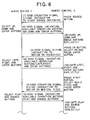
- FIG. 6 is a sequence diagram showing a concrete example of signal exchange between the audio apparatus 1 and remote controller 2.
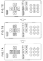
- FIGs. 7A to 7C are a diagram showing what operation buttons are designated on the remote controller 2 in each operational state of the audio apparatus 1.
- the shaded operation buttons are those indicated explicitly (illuminated and vibrated) by the controller 24.
- the remote controller 2 sends the audio apparatus 1 an operation signal giving an instruction to start source switching (1). Consequently, the audio apparatus 1 enters an operational state in which it waits for an instruction to select a source. Therefore, the Up button 232, Down button 233, and Enter button 236 are selected on the audio apparatus 1. Then, the audio apparatus 1 sends the remote controller 2 a signal indicating the selected available operation buttons (Up button 232, Down button 233, and Enter button 236) (2) . In this way, the Up button 232, Down button 233, and Enter button 236 are indicated explicitly on the remote controller 2 as shown in FIG. 7A.
- the remote controller 2 sends the audio apparatus 1 a signal giving an instruction to decide on a source (CD) (3). Consequently, the audio apparatus 1 enters an operational state in which it waits for an instruction to select a musical piece recorded on the CD. Therefore, the Right button 235 and Enter button 236 for selecting and deciding on a musical piece are selected on the audio apparatus 1. Then, the audio apparatus 1 sends the remote controller 2 a signal indicating the selected available operation buttons (Left button 234, Right button 235, and Enter button 236) (4). In this way, the Left button 234, Right button 235, and Enter button 236 are indicated explicitly on the remote controller 2 as shown in FIG. 7B.
- the remote controller 2 sends the audio apparatus 1 an operation signal giving an instruction to decide on a musical piece (5) . Consequently, the audio apparatus 1 enters an operational state in which it waits for an instruction to play back the musical piece as well as an operational state in which it accepts source selection/switching. Therefore, the Play button 237 and Source button 231 are selected on the audio apparatus 1. Then, the audio apparatus 1 sends the remote controller 2 a signal indicating the selected available operation buttons (Play button 237 and Source button 231) (6). In this way, the Play button 237 and Source button 231 are indicated explicitly on the remote controller 2 as shown in FIG. 7C.
- buttons are illuminated and vibrated from among a plurality of operation buttons provided on the control panel 23 of the remote controller 2, the user can understand quickly and precisely what button to press next after pressing a first button.
- vibrating available operation buttons can improve intuitive understanding (information can be conveyed quickly) and effectively supplement other sensory organs. It can also compensate for decreased sensory function of elderly people or weak-sighted people.
- the audio apparatus 1 when the audio apparatus 1 is mounted on an automobile, it can reduce reliance on sight in operating it under special conditions during driving, and thus can improve safety.
- the present invention is not limited to this. It is also possible to configure the present invention so as to select available operation buttons based on the current operational state of the audio apparatus 1 even in the absence of an operation signal from the remote controller 2 and send the remote controller 2 a signal indicating the selected available operation buttons.
- a second embodiment concerns a case in which signals are exchanged between an audio apparatus and a portable communications terminal according to the present invention.
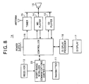
- FIG. 8 is a diagram showing an exemplary schematic inner configuration of an audio apparatus according to the second embodiment.
- components which serve the same functions as corresponding components of the audio apparatus 1 in FIG. 1 are denoted by the same reference numerals as FIG. 1 and description of their functions and the like will be omitted.
- the audio apparatus 1a shown in FIG. 8 differs from the audio apparatus 1 shown in FIG. 1 in that it has a short-range wireless communications controller 20.
- the short-range wireless communications controller 20 is used for data (signal) communications with portable communications terminals and has short-range wireless communications capabilities which are based, for example, on Bluetooth (Japanese registered trademark), a short-range wireless communications technology standard.
- Bluetooth (Japanese registered trademark) communications technology employs a master-slave technology in which apparatuses are classified into either a master apparatus which determines a frequency hopping pattern according to specific processes or a slave apparatus which is located at the remote end and controlled by the master apparatus.
- the audio apparatus 1a is a master apparatus. If the master apparatus recognizes a portable communications terminal, which is a slave apparatus, within a radius of 10 meters, it carries out an authentication process which involves exchanging and verifying an ID number unique to each apparatus with the slave apparatus and generating a link key (encryption key) between the master and slave apparatuses using random numbers. After the authentication process, a connection is established between the master and slave apparatuses, enabling signal communications. Once an authentication process is carried out between master and slave apparatuses, subsequent connections between the master and slave apparatuses are established automatically, based on the link key, enabling signal communications.
- an authentication process is carried out between master and slave apparatuses, subsequent connections between the master and slave apparatuses are established automatically, based on the link key, enabling signal communications.
- FIG. 9 is a diagram showing an exemplary schematic inner configuration of a portable telephone which serves as a portable communications terminal according to the second embodiment of the present invention.
- FIG. 10 is a diagram showing a plurality of operation buttons mounted on a control panel of the portable telephone 31.
- the portable telephone 31 is provided with a microphone 32 for entering speech such as user's voice; a speech recognizer 33 which recognizes the speech entered through the microphone 32; a send-data generator 34 which generates speech data to be transmitted based on the speech recognized by the speech recognizer 33; a transmitter 35 which transmits the speech data generated by the send-data generator 34 to a wireless basestation via an antenna; a receiver 36 which receives various information (data) including the speech data from the wireless basestation; a receive-data analyzer 37 which analyzes the type of various information (data) received by the receiver 36 and outputs the speech data to a speaker 38, and the other data to a controller 45; a display (e.g., liquid crystal display) 40 which displays information from the controller 45; a display processor 39 which has a display driver and carries out processes for displaying the above information on the display 40; a transmitter 41 which serves as a transmission device for transmitting operation signals to the audio apparatus 1a; a receiver 42 which serves as a reception device for receiving operation signals
- the short-range wireless communications controller 43 has short-range wireless communications capabilities which are based on Bluetooth (registered trademark), a short-range wireless communications technology standard. This allows the portable telephone 31 to exchange signals with the audio apparatus 1a as described above.
- the control panel 44 contains a plurality of operation buttons as shown in FIG. 10.
- an Up button 301, Down button 302, Left button 303, Right button 304, and Enter button 305 shown in FIG. 10 serve the same functions, respectively, as the Up button 232, Down button 233, Left button 234, Right button 235, and Enter button 236 on the remote controller 2 shown in FIG. 3;
- a Play button 306, FF (Fast Forward) button 307, Rewind button 308, and Stop button 309 shown in FIG. 10 serve the same functions, respectively, as the Play button 237, FF (Fast Forward) button 238, Rewind button 239, and Stop button 240 on the remote controller 2 shown in FIG.
- a [#] button 311 shown in FIG. 10 serves the same function as the Source button 231 on the remote controller 2 shown in FIG. 3; number buttons 310 shown in FIG. 10 serve the same functions as the channel selector buttons 242; and an [*] button 312 shown in FIG. 10 serves the same function as the Pause button 241 on the remote controller 2 shown in FIG. 3.
- Each of the operation buttons on the portable telephone 31 has illumination and vibration capabilities as is the case with the operation buttons on the remote controller 2.
- the illumination and vibration capabilities are similar to those of the remote controller 2 described in the first embodiment and thus detailed description thereof will be omitted.
- the controller 45 has a CPU (Central Processing Unit) with arithmetic capabilities, a working RAM, a ROM, a nonvolatile memory, etc.
- the controller 45 controls the operation buttons on the control panel 44 to operate the audio apparatus 1a.
- the controller 45 has a capability to detect a press of an operation button on the control panel 44 and outputs an operation signal corresponding to the pressed operation button to the transmitter 41 via the short-range wireless communications controller 43.
- the controller 45 functions as an indication device according to the present invention and has a capability to indicate available operation buttons from among the plurality of operation buttons based on a signal indicating the available operation buttons, received by the receiver 42, and inputted via the short-range wireless communications controller 43.
- the capability to indicate available operation buttons is similar to that of the remote controller 2 described in the first embodiment and thus detailed description thereof will be omitted.
- the audio apparatus 1a carries out processes shown in FIG. 4 as is the case with the first embodiment, and the portable telephone 31 carries out processes shown in FIG. 5. This allows signals to be exchanged between the audio apparatus 1a and portable telephone 31 according to procedures shown in FIG. 6, as is the case with the first embodiment.
- buttons are illuminated and vibrated from among a plurality of operation buttons on the control panel 44 of the portable telephone 31, the user can understand quickly and precisely what button to press next after pressing a first button.
- vibrating available operation buttons can improve intuitive understanding (information can be conveyed quickly) and effectively supplement other sensory organs. It can also compensate for decreased sensory function of elderly people or weak-sighted people.
- the audio apparatus 1a when the audio apparatus 1a is mounted on an automobile, it can reduce reliance on sight in operating it under special conditions during driving, and thus can improve safety.
- the second embodiment is configured mainly such that available operation buttons are selected on the audio apparatus 1a based on an operation signal from the portable telephone 31, the present invention is not limited to this. It is also possible to configure the present invention so as to select available operation buttons based on the current operational state of the audio apparatus 1a even in the absence of an operation signal from the portable telephone 31 and send the portable telephone 31 a signal indicating the selected available operation buttons.
- a third embodiment concerns an audio apparatus serving as an electronic apparatus equipped with an operation panel containing a plurality of operation buttons.
- the remote controller 2 described above is integrated as the operation panel into the audio apparatus.
- FIG. 11 is a diagram showing an exemplary schematic inner configuration of an audio apparatus according to the third embodiment.
- FIG. 12 is a diagram showing a plurality of operation buttons mounted on the operation panel.
- FIG. 13 is a side view of the audio apparatus 1b equipped with the operation panel 57.
- the audio apparatus 1b is provided with a CD player 51 which reads content such as music from a CD and outputs it as a reproduced signal; an MD player 52 which reads content such as music from an MD and outputs it as a reproduced signal; a tuner 53 which receives broadcast waves inputted via an antenna, detects them, and outputs them as a reproduced signal; a speaker 54 which outputs the reproduced signals as sound waves; a display (e.g., liquid crystal display) 55 which displays information from a controller 58; a display processor (microcomputer for display) 56 which has a display driver, etc. and carries out processes for displaying the above information on the display 55; the operation panel 57 containing a plurality of operation buttons for use to operate the audio apparatus 1b; and the controller 58 which controls all the components described above.
- a CD player 51 which reads content such as music from a CD and outputs it as a reproduced signal
- an MD player 52 which reads content such as music from an MD and outputs it as a
- the CD player 51, MD player 52, and tuner 53 serve the same functions, respectively, as the CD player 13, MD player 14, and tuner 15 according to the first embodiment.
- the operation panel 57 containing a plurality of operation buttons for manipulation is connected by wire to the controller 58 unlike in the first and second embodiments.
- the operation panel 57 may be attachable/detachable to/from the body of the audio apparatus.
- the operation panel 57 shown in FIG. 13 may be configured such that it can be removed from the body of the audio apparatus.
- the operation panel 57 contains a plurality of operation buttons as shown in FIG. 12.
- the Source button 501, Up button 502, Down button 503, Left button 504, Right button 505, Enter button 506, Play button 507, FF (Fast Forward) button 508, Rewind button 509, Stop button 510, and Pause button 511 correspond, respectively, to the Source button 231, Up button 232, Down button 233, Left button 234, Right button 235, Enter button 236, Play button 237, FF (Fast Forward) button 238, Rewind button 239, Stop button 240, and Pause button 241 on the remote controller 2 shown in FIG. 3.
- the operation panel 57 has the display 55 built into it.
- the controller 58 has a CPU (Central Processing Unit) with arithmetic capabilities, a working RAM, a ROM, a nonvolatile memory, etc.
- the controller 58 functions as a recognition device according to the present invention and recognizes any operation button pressed from among a plurality of operation buttons on the operation panel 57. It controls the above components based on results of the recognition. For example, the controller 58 switches among the CD player 51, MD player 52, and tuner 53 to output reproduced signals based on an operation signal from the operation panel 57. Thus, if an operation signal instructing playback is received by the operation panel 57, the controller 58 drives and controls the CD player 51 to make it output a reproduced signal.
- a CPU Central Processing Unit
- the controller 58 Based on the operation signal, the controller 58 displays the currently selected source (broadcasting channel in the case of the tuner) and its operational state (e.g., Playing CD) as well as TOC information supplied from the CD player 51 or MD player 52 on the display 55 via the display processor 56.
- This embodiment is similar to the first and second embodiments in this respect.
- controller 58 functions as a selection device and selects available operation buttons from among a plurality of operation buttons on the operation panel 57 based on the recognition results described above. Selection procedures are similar to those in the first embodiment.
- the controller 58 functions as an indication device and indicates the selected available operation buttons. Specifically, the controller 58 serves the same functions as the controller 24 on the remote controller 2 in the first embodiment, and if the available operation button is the Left button 504, for example, the controller 58 explicitly indicates that the Left button 504 is available by illuminating it with the light-emitting element attached to it.
- the controller 58 explicitly indicates that the Left button 504 is available by vibrating it with the vibrator attached to it.
- FIG. 14 is a flowchart showing processes carried out by the CPU in the controller 58 of the audio apparatus 1b to select and indicate available operation buttons. These processes are carried out when a program for selecting and indicating available operation buttons is read from the ROM into the CPU which serves as a computer.
- the controller 58 selects available operation buttons from among the plurality of operation buttons on the operation panel 57 based on results of the recognition (Step S32) . Then, the controller 58 explicitly indicates the selected available operation buttons as described above (Step S33).
- the processes of selecting and indicating available operation buttons in FIG. 14 are carried out by the controller 58, but in another embodiment, they may be carried out, for example, by a display/vibration processor 56a as shown in FIG. 15.
- the display processor 18, which carries out only display processing according to the first embodiment, may be configured to carry out the processes of selecting and indicating available operation buttons.
- buttons are illuminated and vibrated from among a plurality of operation buttons on the operation panel 57, the user can understand quickly and precisely what button to press next after pressing a first button.
- vibrating available operation buttons can improve intuitive understanding (information can be conveyed quickly) and effectively supplement other sensory organs. It can also compensate for decreased sensory function of elderly people or weak-sighted people.
- the audio apparatus 1b or 1c when mounted on an automobile, it can reduce reliance on sight in operating it under special conditions during driving, and thus can improve safety.
- the present invention is not limited to this.
- the first embodiment may be configured such that the remote controller 2 will be equipped with a display (e.g., liquid crystal display) on which marks of available operation buttons (e.g., marks of the Up and Down buttons) will be displayed (navigation assistance capabilities).
- the second embodiment may be configured such that marks of available operation buttons (e.g., marks of the Up and Down buttons) will be displayed on the display 40 of the portable telephone 31 (navigation assistance capabilities) .
- available operation buttons may be indicated by voice through the speaker 38.
- Simpler operability can also be achieved by providing the audio apparatus 1 or 1a with navigation assistance capabilities and displaying similar marks of available operation buttons both on the display of the remote controller 2 or portable telephone 31 and on the display of the audio apparatus 1 or 1a.
Abstract
Description
- The present invention relates to a remote control apparatus, portable communications terminal, and operation panel for remotely operating a multifunctional electronic apparatus. More particularly, it relates to a remote control apparatus, etc. with enhanced operability.
- Recently, electronic apparatuses such as audio apparatuses, VTRs (Videotape Recorders), CD (Compact Disc) apparatuses, DVD (Digital Versatile Disc) apparatuses, and navigation apparatuses have become multifunctional. To accommodate the expanding functionality of such electric apparatuses, remote control apparatuses for remotely operating such apparatuses are configured such that the number of operation buttons is increased, that two or more operational functions are assigned to a single operation button, or that operations are controlled hierarchically according to operating status of an electronic apparatus.
- However, such conventional measures makes it necessary for the user to operate a large number of operation buttons at many levels, resulting in low operability and an increased operator burden. Also, since available operation buttons differ each time, it is not easy for the user to determine what buttons are currently enabled. Besides, it is extremely difficult for those who are poor at electronic apparatuses, advanced in age, or weak-sighted to keep up with multifunctional products.
- It is therefore an object of the present invention to provide a remote control apparatus, electronic apparatus, and available-button indicating method which can achieve simpler operability.
- The above object of the present invention can be achieved by a remote control apparatus for remotely operating an electronic apparatus provided with: a reception device which receives a signal indicating available operation buttons transmitted from the electronic apparatus; and an indication device which explicitly indicates (specifies) available operation buttons from among a plurality of operation buttons based on the received signal which indicates available operation buttons.
- According to the present invention, since available operation buttons are indicated (specified) fromamongaplurality of operation buttons, the user can understand quickly and precisely what buttons are available. Thus, it is possible to achieve simpler operability.
- The above object of the present invention can be achieved by a remote control apparatus for remotely operating an electronic apparatus provided with: a plurality of operation buttons for remotely operating the electronic apparatus; a transmission device which transmits an operation signal to the electronic apparatus in accordance with any operation button pressed from among the operation buttons; a reception device which receives a signal indicating available operation buttons transmitted from the electronic apparatus after the operation signal is transmitted to the electronic apparatus; and an indication device which explicitly indicates available operation buttons from among said plurality of operation buttons based on the received signal which indicates the available operation buttons.
- According to the present invention, since available operation buttons are indicated from among a plurality of operation buttons, the user can understand quickly and precisely what button to press next after pressing a first button. Thus, it is possible to achieve simpler operability.
- In one aspect of the remote control apparatus of the present invention, each of the operation buttons has an illumination capability, and the indication device illuminates the available operation buttons.
- According this aspect, since available operation buttons are illuminated, the user can visually understand available operation buttons.
- In another aspect of the remote control apparatus of the present invention, each of the operation buttons has a vibration capability, and the indication device vibrates the available operation buttons.
- According this aspect, since available operation buttons are vibrated, the user can understand available operation buttons through a tactile sense. Also, this can improve intuitive understanding (information can be conveyed quickly) and effectively supplement other sensory organs.
- In further aspect of the remote control apparatus of the present invention, each of the operation buttons has an illumination capability and vibration capability, and the indication device both illuminates and vibrates the available operation buttons.
- According this aspect, since available operation buttons are both illuminated and vibrated, the user can understand available operation buttons through both visual and tactile senses. Thus, the user can understand more quickly and precisely what buttons are available.
- In further aspect of the remote control apparatus of the present invention, the indication device explicitly indicates the available operation buttons only if the reception device receives a signal which indicates the available operation buttons within a predetermined time after the operation button is pressed.
- The remote control apparatus may be a portable communications terminal such as a portable telephone, PHS (Personal Handy-phone System), PDA (mobile terminal), or the like.
- According this aspect, since available operation buttons are indicated from among a plurality of operation buttons on a portable communications terminal, the user can understand quickly and precisely what buttons are available. Thus, it is possible to achieve simpler operability.
- The above object of the present invention can be achieved by an electronic apparatus provided with: a selection device which selects available operation buttons on a remote control apparatus equipped with a plurality of operation buttons for remotely operating the electronic apparatus; and a transmission device which transmits a signal which indicates the selected available operation buttons to the remote control apparatus.
- According to the present invention, since available operation buttons are selected and a signal indicating them is transmitted to a remote control apparatus, the remote control apparatus can explicitly indicate the available operation buttons based on the signal.
- The above object of the present invention can be achieved by an electronic apparatus provided with: a reception device which receives an operation signal transmitted from a remote control apparatus equipped with a plurality of operation buttons for remotely operating an electronic apparatus; a selection device which selects available operation buttons on the remote control apparatus based on the received operation signal; and a transmission device which transmits a signal which indicates the selected available operation buttons to the remote control apparatus.
- According to the present invention, since subsequently available operation buttons are selected based on an operation signal from a remote control apparatus and a signal indicating them is transmitted to the remote control apparatus, the remote control apparatus can explicitly indicate the available operation buttons based on the signal.
- The above object of the present invention can be achieved by an electronic apparatus equipped with an operation panel which contains a plurality of operation buttons provided with: a recognition device which recognizes any operation button pressed from among the operation buttons; a selection device which selects available operation buttons from among the plurality of operation buttons based on results of the recognition; and an indication device which explicitly indicates the selected available operation buttons.
- According to the present invention, since available operation buttons are indicated from among a plurality of operation buttons, the user can understand quickly and precisely what button to press next after pressing a first button. Thus, it is possible to achieve simpler operability.
- In one aspect of the electronic apparatus of the present invention, each of the operation buttons has an illumination capability; and the indication device illuminates the available operation buttons.
- According this aspect, since available operation buttons are illuminated, the user can visually understand available operation buttons.
- In another aspect of the electronic apparatus of the present invention, each of the operation buttons has a vibration capability, and the indication device vibrates the available operation buttons.
- According this aspect, since available operation buttons are vibrated, the user can understand available operation buttons through a tactile sense. Also, this can improve intuitive understanding (information can be conveyed quickly) and effectively supplement other sensory organs.
- In further aspect of the electronic apparatus of the present invention, each of the operation buttons has an illumination capability and vibration capability, and the indication device both illuminates and vibrates the available operation buttons.
- According this aspect, since available operation buttons are both illuminated and vibrated, the user can understand available operation buttons through both visual and tactile senses. Thus, the user can understand more quickly and precisely what buttons are available.
- In further aspect of the electronic apparatus of the present invention, the operation panel is removably mounted on the electronic apparatus.
- The above object of the present invention can be achieved by an available-button indicating method for explicitly indicating, to the user, operation buttons available for use to remotely operate an electronic apparatus from among a plurality of operation buttons mounted on a remote control apparatus provided with: a step in which the electronic apparatus selects available operation buttons on the remote control apparatus; a step in which the electronic apparatus transmits a signal indicating the selected available operation buttons to the remote control apparatus; and a step in which the remote control apparatus indicates the available operation buttons from among said plurality of operation buttons based on the signal indicating the available operation buttons and transmitted from the electronic apparatus.
- According to the present invention, since available operation buttons are indicated from among a plurality of operation buttons, the user can understand quickly and precisely what buttons are available. Thus, it is possible to achieve simpler operability.
- The above object of the present invention can be achieved by an available-button indicating method for explicitly indicating, to the user, operation buttons available for use to operate an electronic apparatus from among a plurality of operation buttons mounted on a remote control apparatus provided with: a step in which the remote control apparatus transmits an operation signal to the electronic apparatus in accordance with any operation button pressed from among said plurality of operation buttons on the remote control apparatus; a step in which the electronic apparatus selects available operation buttons on the remote control apparatus based on the operation signal transmitted from the remote control apparatus; a step in which the electronic apparatus transmits a signal indicating the selected available operation buttons to the remote control apparatus; and a step in which the remote control apparatus explicitly indicates the available operation buttons from among said plurality of operation buttons based on the signal indicating the available operation buttons and transmitted from the electronic apparatus.
- According to the present invention, since available operation buttons are indicated from among a plurality of operation buttons, the user can understand quickly and precisely what button to press next after pressing a first button. Thus, it is possible to achieve simpler operability.
- In the Drawings;
- FIG. 1 is a diagram showing an exemplary schematic inner configuration of an audio apparatus according to a first embodiment;
- FIG. 2 is a diagram showing an exemplary schematic inner configuration of a remote control apparatus according to the first embodiment;
- FIG. 3 is a diagram showing a plurality of operation buttons
mounted on an operation panel of the
remote control 2; - FIG. 4 is a flowchart showing processes carried out by
a CPU in a
controller 19 of theaudio apparatus 1 to select available operation buttons; - FIG. 5 is a flowchart showing processes carried out by
a CPU in a
controller 24 of theremote control 2 to indicate available operation buttons; - FIG. 6 is a sequence showing a concrete example of signal
exchange between the
audio apparatus 1 andremote control 2; - FIGs. 7A to 7C are a diagram showing what operation buttons
are illuminated on the
remote control 2 in each operational state of theaudio apparatus 1; - FIG. 8 is a diagram showing an exemplary schematic inner configuration of an audio apparatus according to a second embodiment;
- FIG. 9 is a diagram showing an exemplary schematic inner configuration of a portable telephone which serves as a portable communications terminal according to the second embodiment;
- FIG. 10 is a diagram showing a plurality of operation
buttons mounted on a control panel of the
portable telephone 31; - FIG. 11 is a diagram showing an exemplary schematic inner configuration of an audio apparatus according to a third embodiment;
- FIG. 12 is a diagram showing a plurality of operation buttons mounted on an operation panel;
- FIG. 13 is a side view of the
audio apparatus 1b equipped with theoperation panel 57; - FIG. 14 is a flowchart showing processes carried out by
a CPU in a
controller 58 of theaudio apparatus 1b to select and indicate available operation buttons according to the third embodiment; and - FIG. 15 is a diagram showing another exemplary schematic inner configuration of the audio apparatus according to the third embodiment.
-
- Preferred embodiments of the present invention will be described below with reference to the accompanying drawings. Incidentally, the embodiments described below concern cases in which electronic apparatuses according to the present invention are applied to audio apparatuses. It is assumed that such an audio apparatus provides content or other information to the user by switching among a plurality of sources such as CD, MD (Mini Disc), and Tuner.
- A first embodiment concerns a case in which signals are exchanged between the audio apparatus described above and a remote control apparatus according to the present invention.
- FIG. 1 is a diagram showing an exemplary schematic inner configuration of an audio apparatus according to the first embodiment. FIG. 2 is a diagram showing an exemplary schematic inner configuration of a remote control apparatus (hereinafter referred to as a "remote controller") according to the first embodiment. FIG. 3 is a diagram showing a plurality of operation buttons mounted on a control panel of the
remote controller 2. - First, the configuration and functionality of the
audio apparatus 1 will be described with reference to FIG. 1. - As shown in FIG. 1, the
audio apparatus 1 is provided with atransmitter 11 which transmits signals to aremote controller 2 according to instructions from acontroller 19; areceiver 12 which serves as a reception device for receiving operation signals from theremote control 2; aCD player 13 which reads content such as music from a CD and outputs it as a reproduced signal; anMD player 14 which reads content such as music from an MD and outputs it as a reproduced signal; atuner 15 which receives broadcast waves inputted via an antenna, detects them, and outputs them as a reproduced signal; aspeaker 16 which outputs the reproduced signals as sound waves; a display (e.g., liquid crystal display) 17 which displays information from thecontroller 19; a display processor (microcomputer for display) 18 which has a display driver, etc. and carries out processes for displaying the above information on thedisplay 17; and thecontroller 19 which controls all the components described above. - The
transmitter 11 as a transmission device has an infrared-emitting element and the like and transmits a signal indicated by thecontroller 19--for example, a signal which indicates available operation buttons described infrared pulse waves using an infrared band. - The
receiver 12 has an infrared-emitting element and the like. It receives infrared pulse waves of an operation signal transmitted from theremote controller 2 and supplies the operation signal to thecontroller 19 after photoelectric conversion. - The
CD player 13 andMD player 14 rotationally drive an CD or MD, read music from the CD or MD, and output it as a reproduced signal to thespeaker 16, under drive control from thecontroller 19. Also, theCD player 13 andMD player 14 supplies management information (disc title, the titles and number of musical pieces, playback time, and other information) known as TOC (Table Of Content) and stored in the CD and MD, respectively, to thecontroller 19. - The
tuner 15 detects broadcast waves (RF signal) by tuning to the frequency of a broadcasting channel indicated by thecontroller 19 and outputs them as a reproduced signal to thespeaker 16. - The source--the
CD player 13,MD player 14, ortuner 15--from which a reproduced signal should be output to thespeaker 16 is determined by thecontroller 19. - The
controller 19 has a CPU (Central Processing Unit) with arithmetic capabilities, a working RAM, a ROM, a nonvolatile memory, etc. Thecontroller 19 switches among theCD player 13,MD player 14, andtuner 15 to output reproduced signals based on an operation signal received by thereceiver 12. Specifically, if an operation signal instructing playback is received by theremote controller 2, thecontroller 19 drives and controls theCD player 13 to make it output a reproduced signal. - Based on the operation signal, the
controller 19 displays the currently selected source (broadcasting channel in the case of the tuner) and its operational state (e.g., Playing CD) as well as TOC information supplied from theCD player 13 orMD player 14 on thedisplay 17 via thedisplay processor 18. This allows the user to see what source is currently selected, what is its operational state, and if a CD or MD is selected, what musical piece is being played back. - The
controller 19, which functions as a selection device according to the present invention, selects available operation buttons on theremote controller 2 and outputs a signal indicating them to thetransmitter 11. For example, when an operation signal instructing playback (described later) is received, thecontroller 19 selects operation buttons which are needed to be operated during CD playback, such as FF (Fast Forward), Rewind, Stop, and Pause buttons (described later), as available operation buttons based on the operation signal. If CD is selected but stopped (e.g., when the audio apparatus is just powered on), thecontroller 19 selects Left and Right buttons (described later) as available operation buttons and outputs a signal indicating them to thetransmitter 11, even in the absence of an operation signal from theremote controller 2, so that musical pieces recorded on the CD can be selected. - Next, configuration and functionality of the
remote controller 2 will be described with reference to FIG. 2. - As shown in FIG. 2, the
remote controller 2 is provided with atransmitter 21 which serves as a transmission device for transmitting operation signals to theaudio apparatus 1, areceiver 22 which serves as a reception device for receiving a signal indicating available operation buttons from theaudio apparatus 1, acontrol panel 23 equipped with a plurality of operation buttons for remotely operating theaudio apparatus 1, and acontroller 24 which controls all the components described above. - The
transmitter 21 has an infrared-emitting element. When any operation button on thecontrol panel 23 is pressed, thetransmitter 21 transmits an operation signal which corresponds to the operation button as infrared pulse waves using an infrared band at the instruction of thecontroller 24. For example, if a music selection button is pressed, a corresponding operation signal is transmitted as infrared pulse waves. - The
receiver 22 has an infrared-emitting element and the like. It receives infrared pulse waves of a signal indicating available operation buttons transmitted from theaudio apparatus 1 and supplies thecontroller 24 with a signal indicating the available operation buttons after photoelectric conversion. - As shown in FIG. 3, the
control panel 23 contains the following operation buttons: aSource button 231 for transmitting an operation signal which gives an instruction to start source switching, Upbutton 232 and Downbutton 233 for transmitting an operation signal which gives an instruction to select a source,Left button 234 andRight button 235 for transmitting an operation signal which gives an instruction to select a musical piece recorded on a CD or MD,Enter button 236 for transmitting an operation signal which gives an instruction to decide on the source or musical piece selected withbuttons 232 to 235 above,Play button 237 for transmitting an operation signal which gives an instruction to play back the musical piece selected and decided on, FF (Fast Forward)button 238 for transmitting an operation signal which gives a fast forward instruction for the music being played back, Rewind button 239 for transmitting an operation signal which gives a rewind instruction for the music being played back,Stop button 240 for transmitting an operation signal which gives an instruction to stop the music being played back,Pause button 241 for transmitting an operation signal which gives an instruction to pause the music being played back, andchannel selector buttons 242 for transmitting an operation signal which gives an instruction to select and decide on a broadcasting channel. - All the operation buttons are provided with illumination and vibration capabilities. More specifically, each operation button is equipped with a light-emitting element (e.g., light-emitting diode) at a predetermined location on the back side and is illuminated by the light-emitting element. The illumination of the light-emitting elements is controlled by the
controller 24. - Also, each operation button is equipped with a small vibrator at a predetermined location on the back side and vibrates by means of the vibrator. Incidentally, to prevent the other non-vibrating operation buttons from being affected (vibrated) while one operation button is vibrating, vibration-damping rubber is mounted (known vibration proof rubber may be used) in the place where each operation button contacts the
remote controller 2. The vibration of the vibration absorbing elements is controlled by thecontroller 24. - The
controller 24 has a CPU (Central Processing Unit) with arithmetic capabilities, a working RAM, a ROM, a nonvolatile memory, etc. Thecontroller 24 has a capability to detect a press of an operation button on thecontrol panel 23 and outputs an operation signal corresponding to the pressed operation button to thetransmitter 21. Also, thecontroller 24 functions as an indication device according to the present invention and indicates available operation buttons from among the plurality of operation buttons based on a signal indicating the available operation buttons and received by thereceiver 22. For example, if the available operation button is theLeft button 234, thecontroller 24 explicitly indicates that theLeft button 234 is available by illuminating it with the light-emitting element attached to it. - Similarly, if the available operation button is the
Left button 234, thecontroller 24 explicitly indicates that theLeft button 234 is available by vibrating it with the vibrator attached to it. - Next, operation of the
audio apparatus 1 will be described with reference to FIG. 4. FIG. 4 is a flowchart showing processes carried out by the CPU in thecontroller 19 of theaudio apparatus 1 to select available operation buttons. These processes are carried out when a program for selecting available operation buttons is read from the ROM into the CPU which serves as a computer. - Upon receiving infrared pulse waves of an operation signal fromthe
remote controller 2, thereceiver 12 of theaudio apparatus 1 supplies the operation signal to thecontroller 19 after photoelectric conversion. - In FIG. 4, the
controller 19 receives the operation signal supplied from the receiver 12 (Step S1). - Next, the
controller 19 selects available operation buttons based on the received operation signal (Step S2). For example, if an operation signal giving an instruction to start source switching is received, thecontroller 19 enters an operational state in which it waits for an instruction to select a source, and thus it rejects any other instruction such as an instruction to select a musical piece, instruction to play back a musical piece, instruction to select a broadcasting channel, or instruction to make a decision. Therefore, thecontroller 19 selects theUp button 232, Downbutton 233, and Enterbutton 236 as available operation buttons on theremote controller 2. - If the tuner is selected as a source and an instruction to make a decision is received, the
controller 19 enters an operational state in which it waits for an instruction to decide on a broadcasting channel, and thus it rejects, for example, an instruction to select a musical piece and an instruction to decide on a musical piece. Therefore, thecontroller 19 selects thechannel selector buttons 242 andSource button 231 as available operation buttons on theremote controller 2. - Then, the
controller 19 outputs a signal indicating the selected available operation buttons to the transmitter 11 (Step S3). Thus, the signal indicating the available operation buttons is transmitted as infrared pulse waves to theremote controller 2. - Next, operation of the
remote controller 2 will be described with reference to FIG. 5. FIG. 5 is a flowchart showing processes carried out by the CPU in thecontroller 24 of theremote controller 2 to indicate available operation buttons. These processes are carried out when a program for indicating available operation buttons is read from the ROM into the CPU which serves as a computer. - In FIG. 5, the
controller 24 sets a timer value (e.g., "10") (Step S11) . Thecontroller 24, which checks for any press of an operation button on the control panel 23 (Step S12), outputs to thetransmitter 21 an operation signal corresponding to any operation button pressed (Step S13). Then, thecontroller 24 sets a timer value (e.g., "10") again (Step S14) and returns to Step S12. In this way, thecontroller 24 enters a wait state waiting for reception of a signal which indicates available operation buttons from the audio apparatus 1 (hereinafter referred to as the "signal wait state"). Incidentally, the operation signal outputted to thetransmitter 21 is transmitted as infrared pulse waves to theaudio apparatus 1. - If no press of an operation button is detected in Step S12, the
controller 24 goes to Step S15, where it judges whether a signal indicating available operation buttons is received by thereceiver 22. If no signal indicating available operation buttons is received, thecontroller 24 judges whether the timer value is "0" (which means a timeout) (Step S16). If the timer value is not "0," thecontroller 24 decrements it by "1" (Step S17) and returns to Step S12. In this way, each time Step S17 is executed, the timer value is decremented by "1." When the timer value reaches "0" in Step S16, thecontroller 24 gets out of the signal wait state (Step S18). Specifically, when a predetermined time elapses after the operation button is pressed, i.e., when the time required for the timer value to reach "0" elapses in this case, available operation buttons are not indicated explicitly any more in Step S20 (described later) even if a signal indicating the available operation buttons is received. However, if another button is pressed (Step S19) , thecontroller 24 sets a timer value again in Step S14 after going through Step S13. - If a signal indicating available operation buttons is received in Step S15, the
controller 24 explicitly indicates the available operation buttons from among a plurality of operation buttons based on the received signal (Step S20) and sets a timer value again (Step S21) . For example, if theUp button 232, Downbutton 233, and Enterbutton 236 are the available operation buttons, thecontroller 24 indicates them explicitly by illuminating and vibrating them. Alternatively, it is possible to use either illumination or vibration. - Incidentally, if all the operation buttons on the
remote controller 2 become unavailable, a restoration can be effected by refreshing the communication between theaudio apparatus 1 andremote controller 2. - Next, concrete exchange of signals between the
audio apparatus 1 andremote controller 2 will be described with reference to FIGS. 6 and 7. FIG. 6 is a sequence diagram showing a concrete example of signal exchange between theaudio apparatus 1 andremote controller 2. FIGs. 7A to 7C are a diagram showing what operation buttons are designated on theremote controller 2 in each operational state of theaudio apparatus 1. In FIGs 7A to 7C, the shaded operation buttons are those indicated explicitly (illuminated and vibrated) by thecontroller 24. - Referring to FIG. 6, when the
Source button 231 is pressed on theremote controller 2, theremote controller 2 sends theaudio apparatus 1 an operation signal giving an instruction to start source switching (1). Consequently, theaudio apparatus 1 enters an operational state in which it waits for an instruction to select a source. Therefore, theUp button 232, Downbutton 233, and Enterbutton 236 are selected on theaudio apparatus 1. Then, theaudio apparatus 1 sends the remote controller 2 a signal indicating the selected available operation buttons (Upbutton 232, Downbutton 233, and Enter button 236) (2) . In this way, theUp button 232, Downbutton 233, and Enterbutton 236 are indicated explicitly on theremote controller 2 as shown in FIG. 7A. - If the
Up button 232 is pressed and CD is selected and theEnter button 236 is pressed on theremote controller 2, theremote controller 2 sends the audio apparatus 1 a signal giving an instruction to decide on a source (CD) (3). Consequently, theaudio apparatus 1 enters an operational state in which it waits for an instruction to select a musical piece recorded on the CD. Therefore, theRight button 235 andEnter button 236 for selecting and deciding on a musical piece are selected on theaudio apparatus 1. Then, theaudio apparatus 1 sends the remote controller 2 a signal indicating the selected available operation buttons (Left button 234,Right button 235, and Enter button 236) (4). In this way, theLeft button 234,Right button 235, and Enterbutton 236 are indicated explicitly on theremote controller 2 as shown in FIG. 7B. - If, for example, the
Right button 235 is pressed and a musical piece is selected and theEnter button 236 is pressed on theremote controller 2, theremote controller 2 sends theaudio apparatus 1 an operation signal giving an instruction to decide on a musical piece (5) . Consequently, theaudio apparatus 1 enters an operational state in which it waits for an instruction to play back the musical piece as well as an operational state in which it accepts source selection/switching. Therefore, thePlay button 237 andSource button 231 are selected on theaudio apparatus 1. Then, theaudio apparatus 1 sends the remote controller 2 a signal indicating the selected available operation buttons (Play button 237 and Source button 231) (6). In this way, thePlay button 237 andSource button 231 are indicated explicitly on theremote controller 2 as shown in FIG. 7C. - As described above, according to the first embodiment, since available operation buttons are illuminated and vibrated from among a plurality of operation buttons provided on the
control panel 23 of theremote controller 2, the user can understand quickly and precisely what button to press next after pressing a first button. Thus, it is possible to achieve simpler operability. In particular, vibrating available operation buttons can improve intuitive understanding (information can be conveyed quickly) and effectively supplement other sensory organs. It can also compensate for decreased sensory function of elderly people or weak-sighted people. - Furthermore, when the
audio apparatus 1 is mounted on an automobile, it can reduce reliance on sight in operating it under special conditions during driving, and thus can improve safety. - Incidentally, although the first embodiment is configured mainly such that available operation buttons are selected on the
audio apparatus 1 based on an operation signal from theremote controller 2, the present invention is not limited to this. It is also possible to configure the present invention so as to select available operation buttons based on the current operational state of theaudio apparatus 1 even in the absence of an operation signal from theremote controller 2 and send the remote controller 2 a signal indicating the selected available operation buttons. - A second embodiment concerns a case in which signals are exchanged between an audio apparatus and a portable communications terminal according to the present invention.
- FIG. 8 is a diagram showing an exemplary schematic inner configuration of an audio apparatus according to the second embodiment. Of the
audio apparatus 1 shown in FIG. 8, components which serve the same functions as corresponding components of theaudio apparatus 1 in FIG. 1 are denoted by the same reference numerals as FIG. 1 and description of their functions and the like will be omitted. - The audio apparatus 1a shown in FIG. 8 differs from the
audio apparatus 1 shown in FIG. 1 in that it has a short-rangewireless communications controller 20. The short-rangewireless communications controller 20 is used for data (signal) communications with portable communications terminals and has short-range wireless communications capabilities which are based, for example, on Bluetooth (Japanese registered trademark), a short-range wireless communications technology standard. The Bluetooth (Japanese registered trademark) communications technology employs a master-slave technology in which apparatuses are classified into either a master apparatus which determines a frequency hopping pattern according to specific processes or a slave apparatus which is located at the remote end and controlled by the master apparatus. - Assume, for example, that the audio apparatus 1a is a master apparatus. If the master apparatus recognizes a portable communications terminal, which is a slave apparatus, within a radius of 10 meters, it carries out an authentication process which involves exchanging and verifying an ID number unique to each apparatus with the slave apparatus and generating a link key (encryption key) between the master and slave apparatuses using random numbers. After the authentication process, a connection is established between the master and slave apparatuses, enabling signal communications. Once an authentication process is carried out between master and slave apparatuses, subsequent connections between the master and slave apparatuses are established automatically, based on the link key, enabling signal communications.
- FIG. 9 is a diagram showing an exemplary schematic inner configuration of a portable telephone which serves as a portable communications terminal according to the second embodiment of the present invention. FIG. 10 is a diagram showing a plurality of operation buttons mounted on a control panel of the
portable telephone 31. - As shown in FIG. 9, the portable telephone 31 is provided with a microphone 32 for entering speech such as user's voice; a speech recognizer 33 which recognizes the speech entered through the microphone 32; a send-data generator 34 which generates speech data to be transmitted based on the speech recognized by the speech recognizer 33; a transmitter 35 which transmits the speech data generated by the send-data generator 34 to a wireless basestation via an antenna; a receiver 36 which receives various information (data) including the speech data from the wireless basestation; a receive-data analyzer 37 which analyzes the type of various information (data) received by the receiver 36 and outputs the speech data to a speaker 38, and the other data to a controller 45; a display (e.g., liquid crystal display) 40 which displays information from the controller 45; a display processor 39 which has a display driver and carries out processes for displaying the above information on the display 40; a transmitter 41 which serves as a transmission device for transmitting operation signals to the audio apparatus 1a; a receiver 42 which serves as a reception device for receiving operation signals indicating available operation buttons from the audio apparatus 1a; a short-range wireless communications controller 43 which controls short-range wireless signal communications by controlling the transmitter 41 and receiver 42; a control panel 44 which contains a plurality of operation buttons for use to enter a telephone number and the like and remotely control the audio apparatus 1a; and the controller 45 which controls all the components described above.
- As with the short-range
wireless communications controller 20 on the audio apparatus 1a, the short-rangewireless communications controller 43 has short-range wireless communications capabilities which are based on Bluetooth (registered trademark), a short-range wireless communications technology standard. This allows theportable telephone 31 to exchange signals with the audio apparatus 1a as described above. - The
control panel 44 contains a plurality of operation buttons as shown in FIG. 10. When theportable telephone 31 establishes communication with the audio apparatus 1a, anUp button 301, Downbutton 302,Left button 303,Right button 304, and Enterbutton 305 shown in FIG. 10 serve the same functions, respectively, as theUp button 232, Downbutton 233,Left button 234,Right button 235, and Enterbutton 236 on theremote controller 2 shown in FIG. 3; aPlay button 306, FF (Fast Forward)button 307,Rewind button 308, andStop button 309 shown in FIG. 10 serve the same functions, respectively, as thePlay button 237, FF (Fast Forward)button 238, Rewind button 239, andStop button 240 on theremote controller 2 shown in FIG. 3; a [#]button 311 shown in FIG. 10 serves the same function as theSource button 231 on theremote controller 2 shown in FIG. 3;number buttons 310 shown in FIG. 10 serve the same functions as thechannel selector buttons 242; and an [*]button 312 shown in FIG. 10 serves the same function as thePause button 241 on theremote controller 2 shown in FIG. 3. - Each of the operation buttons on the
portable telephone 31 has illumination and vibration capabilities as is the case with the operation buttons on theremote controller 2. The illumination and vibration capabilities are similar to those of theremote controller 2 described in the first embodiment and thus detailed description thereof will be omitted. - The
controller 45 has a CPU (Central Processing Unit) with arithmetic capabilities, a working RAM, a ROM, a nonvolatile memory, etc. When theportable telephone 31 establishes communication with the audio apparatus 1a as described above, thecontroller 45 controls the operation buttons on thecontrol panel 44 to operate the audio apparatus 1a. Thecontroller 45 has a capability to detect a press of an operation button on thecontrol panel 44 and outputs an operation signal corresponding to the pressed operation button to thetransmitter 41 via the short-rangewireless communications controller 43. Also, thecontroller 45 functions as an indication device according to the present invention and has a capability to indicate available operation buttons from among the plurality of operation buttons based on a signal indicating the available operation buttons, received by thereceiver 42, and inputted via the short-rangewireless communications controller 43. The capability to indicate available operation buttons is similar to that of theremote controller 2 described in the first embodiment and thus detailed description thereof will be omitted. - With the above configuration, the audio apparatus 1a carries out processes shown in FIG. 4 as is the case with the first embodiment, and the
portable telephone 31 carries out processes shown in FIG. 5. This allows signals to be exchanged between the audio apparatus 1a andportable telephone 31 according to procedures shown in FIG. 6, as is the case with the first embodiment. - As described above, according to the second embodiment, since available operation buttons are illuminated and vibrated from among a plurality of operation buttons on the
control panel 44 of theportable telephone 31, the user can understand quickly and precisely what button to press next after pressing a first button. Thus, it is possible to achieve simpler operability. In particular, vibrating available operation buttons can improve intuitive understanding (information can be conveyed quickly) and effectively supplement other sensory organs. It can also compensate for decreased sensory function of elderly people or weak-sighted people. - Furthermore, when the audio apparatus 1a is mounted on an automobile, it can reduce reliance on sight in operating it under special conditions during driving, and thus can improve safety.
- Incidentally, although the second embodiment is configured mainly such that available operation buttons are selected on the audio apparatus 1a based on an operation signal from the
portable telephone 31, the present invention is not limited to this. It is also possible to configure the present invention so as to select available operation buttons based on the current operational state of the audio apparatus 1a even in the absence of an operation signal from theportable telephone 31 and send the portable telephone 31 a signal indicating the selected available operation buttons. - A third embodiment concerns an audio apparatus serving as an electronic apparatus equipped with an operation panel containing a plurality of operation buttons. In other words, according to this embodiment, the
remote controller 2 described above is integrated as the operation panel into the audio apparatus. - FIG. 11 is a diagram showing an exemplary schematic inner configuration of an audio apparatus according to the third embodiment. FIG. 12 is a diagram showing a plurality of operation buttons mounted on the operation panel. FIG. 13 is a side view of the
audio apparatus 1b equipped with theoperation panel 57. - As shown in FIG. 11, the
audio apparatus 1b is provided with aCD player 51 which reads content such as music from a CD and outputs it as a reproduced signal; anMD player 52 which reads content such as music from an MD and outputs it as a reproduced signal; atuner 53 which receives broadcast waves inputted via an antenna, detects them, and outputs them as a reproduced signal; aspeaker 54 which outputs the reproduced signals as sound waves; a display (e.g., liquid crystal display) 55 which displays information from acontroller 58; a display processor (microcomputer for display) 56 which has a display driver, etc. and carries out processes for displaying the above information on thedisplay 55; theoperation panel 57 containing a plurality of operation buttons for use to operate theaudio apparatus 1b; and thecontroller 58 which controls all the components described above. - The
CD player 51,MD player 52, andtuner 53 serve the same functions, respectively, as theCD player 13,MD player 14, andtuner 15 according to the first embodiment. - According to the third embodiment, the
operation panel 57 containing a plurality of operation buttons for manipulation is connected by wire to thecontroller 58 unlike in the first and second embodiments. However, theoperation panel 57 may be attachable/detachable to/from the body of the audio apparatus. In other words, theoperation panel 57 shown in FIG. 13 may be configured such that it can be removed from the body of the audio apparatus. - The
operation panel 57 contains a plurality of operation buttons as shown in FIG. 12. TheSource button 501, Upbutton 502, Downbutton 503,Left button 504,Right button 505,Enter button 506,Play button 507, FF (Fast Forward)button 508,Rewind button 509,Stop button 510, and Pause button 511 correspond, respectively, to theSource button 231, Upbutton 232, Downbutton 233,Left button 234,Right button 235,Enter button 236,Play button 237, FF (Fast Forward)button 238, Rewind button 239,Stop button 240, andPause button 241 on theremote controller 2 shown in FIG. 3. Besides, theoperation panel 57 has thedisplay 55 built into it. - The
controller 58 has a CPU (Central Processing Unit) with arithmetic capabilities, a working RAM, a ROM, a nonvolatile memory, etc. Thecontroller 58 functions as a recognition device according to the present invention and recognizes any operation button pressed from among a plurality of operation buttons on theoperation panel 57. It controls the above components based on results of the recognition. For example, thecontroller 58 switches among theCD player 51,MD player 52, andtuner 53 to output reproduced signals based on an operation signal from theoperation panel 57. Thus, if an operation signal instructing playback is received by theoperation panel 57, thecontroller 58 drives and controls theCD player 51 to make it output a reproduced signal. - Based on the operation signal, the
controller 58 displays the currently selected source (broadcasting channel in the case of the tuner) and its operational state (e.g., Playing CD) as well as TOC information supplied from theCD player 51 orMD player 52 on thedisplay 55 via thedisplay processor 56. This embodiment is similar to the first and second embodiments in this respect. - Also, the
controller 58 functions as a selection device and selects available operation buttons from among a plurality of operation buttons on theoperation panel 57 based on the recognition results described above. Selection procedures are similar to those in the first embodiment. - Furthermore, the
controller 58 functions as an indication device and indicates the selected available operation buttons. Specifically, thecontroller 58 serves the same functions as thecontroller 24 on theremote controller 2 in the first embodiment, and if the available operation button is theLeft button 504, for example, thecontroller 58 explicitly indicates that theLeft button 504 is available by illuminating it with the light-emitting element attached to it. - Similarly, if the available operation button is the
Left button 504, thecontroller 58 explicitly indicates that theLeft button 504 is available by vibrating it with the vibrator attached to it. - FIG. 14 is a flowchart showing processes carried out by the CPU in the
controller 58 of theaudio apparatus 1b to select and indicate available operation buttons. These processes are carried out when a program for selecting and indicating available operation buttons is read from the ROM into the CPU which serves as a computer. - In FIG. 14, when any of a plurality of operation buttons is pressed on the
operation panel 57 of theaudio apparatus 1b, a signal corresponding to the pressed operation button is output to thecontroller 58, which then recognizes what operation button is pressed (Step S31). - Next, the
controller 58 selects available operation buttons from among the plurality of operation buttons on theoperation panel 57 based on results of the recognition (Step S32) . Then, thecontroller 58 explicitly indicates the selected available operation buttons as described above (Step S33). - According to the third embodiment, the processes of selecting and indicating available operation buttons in FIG. 14 are carried out by the
controller 58, but in another embodiment, they may be carried out, for example, by a display/vibration processor 56a as shown in FIG. 15. In other word, thedisplay processor 18, which carries out only display processing according to the first embodiment, may be configured to carry out the processes of selecting and indicating available operation buttons. - As described above, according to the third embodiment, since available operation buttons are illuminated and vibrated from among a plurality of operation buttons on the
operation panel 57, the user can understand quickly and precisely what button to press next after pressing a first button. Thus, it is possible to achieve simpler operability. In particular, vibrating available operation buttons can improve intuitive understanding (information can be conveyed quickly) and effectively supplement other sensory organs. It can also compensate for decreased sensory function of elderly people or weak-sighted people. - Furthermore, when the
audio apparatus - Incidentally, although the above embodiments are configured such that available operation buttons are indicated by means of illumination and vibration, the present invention is not limited to this. For example, the first embodiment may be configured such that the
remote controller 2 will be equipped with a display (e.g., liquid crystal display) on which marks of available operation buttons (e.g., marks of the Up and Down buttons) will be displayed (navigation assistance capabilities). Also, the second embodiment may be configured such that marks of available operation buttons (e.g., marks of the Up and Down buttons) will be displayed on thedisplay 40 of the portable telephone 31 (navigation assistance capabilities) . Also, in the second embodiment, available operation buttons may be indicated by voice through thespeaker 38. - Simpler operability can also be achieved by providing the
audio apparatus 1 or 1a with navigation assistance capabilities and displaying similar marks of available operation buttons both on the display of theremote controller 2 orportable telephone 31 and on the display of theaudio apparatus 1 or 1a. - The invention may be embodied in other specific forms without departing from the spirit or essential characteristics thereof. The present embodiments are therefore to be considered in all respects as illustrative and not restrictive, the scope of the invention being indicated by the appended claims rather than by the foregoing description and all changes which come within the meaning and range of equivalency of the claims are therefore intended to be embraced therein.
Claims (18)
- A remote control apparatus for remotely operating an electronic apparatus, characterized in that the apparatus (2,31) comprises:a reception device (22) which receives a signal indicating available operation buttons transmitted from the electronic apparatus (1, 1a); andan indication device (24) which explicitly indicates available operation buttons from among a plurality of operation buttons based on the received signal which indicates available operation buttons.
- A remote control apparatus for remotely operating an electronic apparatus, characterized in that the apparatus (2, 31) comprises:a plurality of operation buttons for remotely operating the electronic apparatus (1, 1a);a transmission device (21) which transmits an operation signal to the electronic apparatus (1, 1a) in accordance with any operation button pressed from among the operation buttons;a reception device (22) which receives a signal indicating available operation buttons transmitted from the electronic apparatus after the operation signal is transmitted to the electronic apparatus (1, 1a); andan indication device (24) which explicitly indicates available operation buttons from among said plurality of operation buttons based on the received signal which indicates the available operation buttons.
- The remote control apparatus (2,31) according to claim 1 or 2, wherein:each of the operation buttons has an illumination capability; andthe indication device (24) illuminates the available operation buttons.
- The remote control apparatus (2,31) according to claim 1 or 2, wherein:each of the operation buttons has a vibration capability; andthe indication device (24) vibrates the available operation buttons.
- The remote control apparatus (2,31) according to claim 1 or 2, wherein:each of the operation buttons has an illumination capability and vibration capability; andthe indication device (24) both illuminates and vibrates the available operation buttons.
- The remote control apparatus (2,31) according to claim 2, wherein:the indication device (24) explicitly indicates the available operation buttons only if the reception device receives a signal which indicates the available operation buttons within a predetermined time after the operation button is pressed.
- The remote control apparatus (2,31) according to any of claims 1 to 6, wherein the remote control apparatus (2,31) is a portable communications terminal (2,31).
- An electronic apparatus characterized in that the apparatus (1, 1a) comprises:a selection device (19) which selects available operation buttons on a remote control apparatus (2,31) equipped with a plurality of operation buttons for remotely operating the electronic apparatus (1, 1a); anda transmission device (11) which transmits a signal which indicates the selected available operation buttons to the remote control apparatus (2,31).
- An electronic apparatus characterized in that the apparatus (1, 1a) comprises:a reception device (12) which receives an operation signal transmitted from a remote control apparatus (2, 31) equipped with a plurality of operation buttons for remotely operating the electronic apparatus (1, 1a)a selection device (19) which selects available operation buttons on the remote control apparatus (2,31) based on the received operation signal; anda transmission device (11) which transmits a signal which indicates the selected available operation buttons to the remote control apparatus (2,31).
- The electronic apparatus (1, 1a) according to claim 8 or 9, wherein the remote control apparatus (2,31) is a portable communications terminal (2, 31).
- An electronic apparatus equipped with an operation panel which contains a plurality of operation buttons, characterized in that the apparatus (1b, 1c comprises:a recognition device (56a,58,58a) which recognizes any operation button pressed from among the operation buttons;a selection device (56a, 58,58a) which selects available operation buttons from among the plurality of operation buttons based on results of the recognition; andan indication device (56a,58,58a) which explicitly indicates the selected available operation buttons.
- The electronic apparatus (1b, 1c) according to claim 11, wherein:each of the operation buttons has an illumination capability; andthe indication device (56a, 58, 58a) illuminates the available operation buttons.
- The electronic apparatus (1b, 1c) according to claim 11, wherein:each of the operation buttons has a vibration capability; andthe indication device (56a,58,58a) vibrates the available operation buttons.
- The electronic apparatus (1b, 1c) according to claim 11, wherein:each of the operation buttons has an illumination capability and vibration capability; andthe indication device (56a,58,58a) both illuminates and vibrates the available operation buttons.
- The electronic apparatus (1b, 1c) according to any of claims 11 to 14, wherein:the operation panel (57) is removably mounted on the electronic apparatus.
- An available-button indicating method for explicitly indicating, to the user, operation buttons available for use to remotely operate an electronic apparatus from among a plurality of operation buttons mounted on a remote control apparatus, characterized in that the method comprises:a step in which the electronic apparatus (1, 1a) selects available operation buttons on the remote control apparatus (2,31);a step in which the electronic apparatus (1, 1a) transmits a signal indicating the selected available operation buttons to the remote control apparatus (2,31); anda step in which the remote control apparatus (2,31) indicates the available operation buttons from among said plurality of operation buttons based on the signal indicating the available operation buttons and transmitted from the electronic apparatus (1,1a).
- An available-button indicating method for explicitly indicating, to the user, operation buttons available for use to operate an electronic apparatus from among a plurality of operation buttons mounted on a remote control apparatus, characterized in that the method comprises:a step in which the remote control apparatus (2,31) transmits an operation signal to the electronic apparatus in accordance with any operation button pressed from among said plurality of operation buttons on the remote control apparatus (2,31);a step in which the electronic apparatus (1, 1a) selects available operation buttons on the remote control apparatus (2,31) based on the operation signal transmitted from the remote control apparatus (2,31);a step in which the electronic apparatus (1, 1a) transmits a signal indicating the selected available operation buttons to the remote control apparatus (2,31); anda step in which the remote control apparatus (2,31) explicitly indicates the available operation buttons from among said plurality of operation buttons based on the signal indicating the available operation buttons and transmitted from the electronic apparatus (1,1a).
- The available-button indicating method according to claim 16 or 17, wherein the remote control apparatus (2,31) isaportable communications terminal (2,31).
Priority Applications (1)
| Application Number | Priority Date | Filing Date | Title |
|---|---|---|---|
| EP05001622A EP1526438B1 (en) | 2002-02-28 | 2003-02-11 | Remote control apparatus, electronic apparatus, and available-button indicating method |
Applications Claiming Priority (2)
| Application Number | Priority Date | Filing Date | Title |
|---|---|---|---|
| JP2002052781A JP4004817B2 (en) | 2002-02-28 | 2002-02-28 | Remote control device, electronic device, and electronic device system |
| JP2002052781 | 2002-02-28 |
Related Child Applications (1)
| Application Number | Title | Priority Date | Filing Date |
|---|---|---|---|
| EP05001622A Division EP1526438B1 (en) | 2002-02-28 | 2003-02-11 | Remote control apparatus, electronic apparatus, and available-button indicating method |
Publications (3)
| Publication Number | Publication Date |
|---|---|
| EP1341316A2 true EP1341316A2 (en) | 2003-09-03 |
| EP1341316A3 EP1341316A3 (en) | 2004-05-19 |
| EP1341316B1 EP1341316B1 (en) | 2007-01-24 |
Family
ID=27678538
Family Applications (2)
| Application Number | Title | Priority Date | Filing Date |
|---|---|---|---|
| EP03250842A Expired - Lifetime EP1341316B1 (en) | 2002-02-28 | 2003-02-11 | Remote control apparatus, electronic apparatus, and available-button indicating method |
| EP05001622A Expired - Lifetime EP1526438B1 (en) | 2002-02-28 | 2003-02-11 | Remote control apparatus, electronic apparatus, and available-button indicating method |
Family Applications After (1)
| Application Number | Title | Priority Date | Filing Date |
|---|---|---|---|
| EP05001622A Expired - Lifetime EP1526438B1 (en) | 2002-02-28 | 2003-02-11 | Remote control apparatus, electronic apparatus, and available-button indicating method |
Country Status (4)
| Country | Link |
|---|---|
| US (1) | US7333025B2 (en) |
| EP (2) | EP1341316B1 (en) |
| JP (1) | JP4004817B2 (en) |
| DE (2) | DE60311335T2 (en) |
Cited By (4)
| Publication number | Priority date | Publication date | Assignee | Title |
|---|---|---|---|---|
| EP1659828A1 (en) * | 2004-11-18 | 2006-05-24 | Samsung Electronics Co., Ltd. | Microwave Oven having an Illuminated Guide Line |
| EP2409488A1 (en) * | 2009-03-16 | 2012-01-25 | EchoStar Technologies L.L.C. | Backlighting remote controls |
| US10198066B2 (en) | 2008-03-27 | 2019-02-05 | DISH Technologies L.L.C. | Reduction of power consumption in remote control electronics |
| US11126397B2 (en) | 2004-10-27 | 2021-09-21 | Chestnut Hill Sound, Inc. | Music audio control and distribution system in a location |
Families Citing this family (20)
| Publication number | Priority date | Publication date | Assignee | Title |
|---|---|---|---|---|
| US20050221895A1 (en) * | 2004-04-02 | 2005-10-06 | Microsoft Corporation | Binding of wireless game controller to host |
| US20050267998A1 (en) * | 2004-05-27 | 2005-12-01 | Ferguson Alan L | Interchangeable communication modules for work machines |
| US8090309B2 (en) | 2004-10-27 | 2012-01-03 | Chestnut Hill Sound, Inc. | Entertainment system with unified content selection |
| US7885622B2 (en) | 2004-10-27 | 2011-02-08 | Chestnut Hill Sound Inc. | Entertainment system with bandless tuning |
| JP2006165811A (en) * | 2004-12-03 | 2006-06-22 | Nippon Hoso Kyokai <Nhk> | Remote control operation presentation device and remote control operation presentation program |
| US8710950B2 (en) * | 2004-12-23 | 2014-04-29 | Hill-Rom Services, Inc. | Wireless control system for a patient support apparatus |
| CN100570548C (en) * | 2005-01-13 | 2009-12-16 | 富士通株式会社 | Electronic equipment and control method |
| JP4761819B2 (en) * | 2005-04-26 | 2011-08-31 | 京セラ株式会社 | Portable viewing device |
| JP2006350826A (en) * | 2005-06-17 | 2006-12-28 | Toshiba Corp | Controller and control method |
| JP2007006369A (en) * | 2005-06-27 | 2007-01-11 | Pioneer Electronic Corp | Remote controller and viewing system including the same |
| JP4615409B2 (en) * | 2005-09-27 | 2011-01-19 | 京セラ株式会社 | Portable electronic devices |
| JP2008072622A (en) * | 2006-09-15 | 2008-03-27 | Sharp Corp | Remote control system and remote control device |
| JP2008152598A (en) * | 2006-12-19 | 2008-07-03 | Pioneer Electronic Corp | Device and operation input supporting method |
| US20090053997A1 (en) * | 2007-08-24 | 2009-02-26 | Motorola, Inc. | Dynamic user interface for displaying connection status and method thereof |
| US20090081966A1 (en) * | 2007-09-25 | 2009-03-26 | Belkin International, Inc. | Communications device for remotely controlling an electrical device and method of manufacturing same |
| JP5455254B2 (en) * | 2011-09-20 | 2014-03-26 | Necシステムテクノロジー株式会社 | Computer, remote control system, remote operation support method, and program |
| US8922615B2 (en) * | 2011-12-16 | 2014-12-30 | Logitech Europe S.A. | Customizing input to a videoconference using a remote control device |
| JP5849111B2 (en) * | 2013-02-18 | 2016-01-27 | アークレイ株式会社 | Medical measuring device and measuring system |
| US20170195735A1 (en) * | 2015-12-31 | 2017-07-06 | Nagravision S.A. | Method and apparatus for peripheral context management |
| CN110383767B (en) * | 2019-06-05 | 2023-07-11 | 深圳市汇顶科技股份有限公司 | Topology switching method, device and system based on synchronous link and storage medium |
Citations (4)
| Publication number | Priority date | Publication date | Assignee | Title |
|---|---|---|---|---|
| US4746919A (en) * | 1986-03-28 | 1988-05-24 | Rca Licensing Corporation | Remote control system with key function display provisions |
| EP0872996A2 (en) * | 1997-04-17 | 1998-10-21 | Nokia Mobile Phones Ltd. | User interface for a telephone apparatus with guide lights |
| US6005490A (en) * | 1996-07-12 | 1999-12-21 | Kabushiki Kaisha Toshiba | Bidirectional remote control apparatus |
| EP1030517A1 (en) * | 1999-02-19 | 2000-08-23 | Sharp Kabushiki Kaisha | Bidirectional remote control system |
Family Cites Families (7)
| Publication number | Priority date | Publication date | Assignee | Title |
|---|---|---|---|---|
| JPH0348986A (en) | 1989-07-17 | 1991-03-01 | Toyo Commun Equip Co Ltd | Toll collecting system for toll road or the like |
| US5282028A (en) * | 1990-11-27 | 1994-01-25 | Scientific-Atlanta, Inc. | Remote control for digital music terminal with synchronized communications |
| JPH04299695A (en) * | 1991-03-27 | 1992-10-22 | Fujitsu General Ltd | Remote controller |
| US5506563A (en) * | 1994-04-12 | 1996-04-09 | Jonic; Danko | Motor vehicle anti-theft security system |
| JPH0946770A (en) | 1995-07-26 | 1997-02-14 | Matsushita Electric Ind Co Ltd | Video cd player |
| JP3501038B2 (en) * | 1999-10-06 | 2004-02-23 | 日本電気株式会社 | Mobile terminal system, mobile terminal used for it |
| KR100333840B1 (en) * | 1999-10-12 | 2002-04-22 | 이철우 | A wireless telephone combined a remotecontroll ed device |
-
2002
- 2002-02-28 JP JP2002052781A patent/JP4004817B2/en not_active Expired - Fee Related
-
2003
- 2003-02-11 EP EP03250842A patent/EP1341316B1/en not_active Expired - Lifetime
- 2003-02-11 DE DE60311335T patent/DE60311335T2/en not_active Expired - Lifetime
- 2003-02-11 EP EP05001622A patent/EP1526438B1/en not_active Expired - Lifetime
- 2003-02-11 DE DE60305186T patent/DE60305186T2/en not_active Expired - Lifetime
- 2003-02-27 US US10/374,093 patent/US7333025B2/en not_active Expired - Fee Related
Patent Citations (4)
| Publication number | Priority date | Publication date | Assignee | Title |
|---|---|---|---|---|
| US4746919A (en) * | 1986-03-28 | 1988-05-24 | Rca Licensing Corporation | Remote control system with key function display provisions |
| US6005490A (en) * | 1996-07-12 | 1999-12-21 | Kabushiki Kaisha Toshiba | Bidirectional remote control apparatus |
| EP0872996A2 (en) * | 1997-04-17 | 1998-10-21 | Nokia Mobile Phones Ltd. | User interface for a telephone apparatus with guide lights |
| EP1030517A1 (en) * | 1999-02-19 | 2000-08-23 | Sharp Kabushiki Kaisha | Bidirectional remote control system |
Non-Patent Citations (1)
| Title |
|---|
| PATENT ABSTRACTS OF JAPAN vol. 017, no. 125 (E-1332), 16 March 1993 (1993-03-16) & JP 04 299695 A (FUJITSU GENERAL LTD), 22 October 1992 (1992-10-22) * |
Cited By (5)
| Publication number | Priority date | Publication date | Assignee | Title |
|---|---|---|---|---|
| US11126397B2 (en) | 2004-10-27 | 2021-09-21 | Chestnut Hill Sound, Inc. | Music audio control and distribution system in a location |
| EP1659828A1 (en) * | 2004-11-18 | 2006-05-24 | Samsung Electronics Co., Ltd. | Microwave Oven having an Illuminated Guide Line |
| US7294813B2 (en) | 2004-11-18 | 2007-11-13 | Samsung Electronics Co., Ltd. | Microwave oven having an illuminated guide line |
| US10198066B2 (en) | 2008-03-27 | 2019-02-05 | DISH Technologies L.L.C. | Reduction of power consumption in remote control electronics |
| EP2409488A1 (en) * | 2009-03-16 | 2012-01-25 | EchoStar Technologies L.L.C. | Backlighting remote controls |
Also Published As
| Publication number | Publication date |
|---|---|
| JP2003259147A (en) | 2003-09-12 |
| EP1341316B1 (en) | 2007-01-24 |
| DE60305186D1 (en) | 2006-06-14 |
| DE60311335D1 (en) | 2007-03-15 |
| US20030162494A1 (en) | 2003-08-28 |
| EP1526438A2 (en) | 2005-04-27 |
| EP1526438A3 (en) | 2005-05-04 |
| EP1526438B1 (en) | 2006-05-10 |
| US7333025B2 (en) | 2008-02-19 |
| DE60305186T2 (en) | 2006-09-28 |
| JP4004817B2 (en) | 2007-11-07 |
| EP1341316A3 (en) | 2004-05-19 |
| DE60311335T2 (en) | 2007-10-31 |
Similar Documents
| Publication | Publication Date | Title |
|---|---|---|
| US7333025B2 (en) | Remote control apparatus, electronic apparatus, and available-button indicating method | |
| EP1944953A1 (en) | Audio output system and method for information processing terminal | |
| JP4842785B2 (en) | In-vehicle electronic system and in-vehicle electronic device | |
| JP2004022139A (en) | Electronic device set, first and second electronic device, and computer program | |
| CN102056766B (en) | Electronic device and electronic system | |
| JP4183588B2 (en) | In-vehicle audio equipment | |
| CN102056768B (en) | Vehicle-mounted device | |
| JP2004207924A (en) | Rf output channel setting apparatus | |
| KR20000017542U (en) | Apparatus for controlling reservation of broadcasting program using the multi-remote controller | |
| JP4961264B2 (en) | In-vehicle system, navigation device, and playback device | |
| KR20050099139A (en) | Versatile portable charger and its control method using mobile terminal | |
| JP3203713B2 (en) | Radio receiver with remote control | |
| KR100218908B1 (en) | Custom code changing method | |
| JP2007094297A (en) | Portable karaoke machine | |
| KR200364775Y1 (en) | Voice equipment for vehicle | |
| KR200408527Y1 (en) | Portable FM transmitter | |
| KR200281453Y1 (en) | Wireless portable FM linker for audio signal output | |
| KR200317020Y1 (en) | Handset Equipped with Portable Multi-Function Remote Control | |
| KR200178563Y1 (en) | Apparatus for remote controller with a radio frequency receiver | |
| KR20050093660A (en) | Method for processing data in the mobile terminal | |
| JPS63170186A (en) | Sound apparatus for loading on motorcycle | |
| KR20070122298A (en) | Hands free apparatus for vehicle and control method thereof | |
| KR20060010635A (en) | Mp3 phone and external speaker for outputting music file using the mp3 phone and audio output system of mp3 phone using optical transmission | |
| JP2001285113A (en) | Radio communication equipment | |
| JP2001343986A (en) | Acoustic device, audio guide method, and recording medium |
Legal Events
| Date | Code | Title | Description |
|---|---|---|---|
| PUAI | Public reference made under article 153(3) epc to a published international application that has entered the european phase |
Free format text: ORIGINAL CODE: 0009012 |
|
| AK | Designated contracting states |
Kind code of ref document: A2 Designated state(s): AT BE BG CH CY CZ DE DK EE ES FI FR GB GR HU IE IT LI LU MC NL PT SE SI SK TR |
|
| AX | Request for extension of the european patent |
Extension state: AL LT LV MK RO |
|
| PUAL | Search report despatched |
Free format text: ORIGINAL CODE: 0009013 |
|
| AK | Designated contracting states |
Kind code of ref document: A3 Designated state(s): AT BE BG CH CY CZ DE DK EE ES FI FR GB GR HU IE IT LI LU MC NL PT SE SI SK TR |
|
| AX | Request for extension of the european patent |
Extension state: AL LT LV MK RO |
|
| RIC1 | Information provided on ipc code assigned before grant |
Ipc: 7G 06F 3/023 B Ipc: 7H 04B 1/20 A |
|
| 17P | Request for examination filed |
Effective date: 20040611 |
|
| 17Q | First examination report despatched |
Effective date: 20040901 |
|
| AKX | Designation fees paid |
Designated state(s): DE FR GB |
|
| GRAP | Despatch of communication of intention to grant a patent |
Free format text: ORIGINAL CODE: EPIDOSNIGR1 |
|
| GRAS | Grant fee paid |
Free format text: ORIGINAL CODE: EPIDOSNIGR3 |
|
| GRAA | (expected) grant |
Free format text: ORIGINAL CODE: 0009210 |
|
| AK | Designated contracting states |
Kind code of ref document: B1 Designated state(s): DE FR GB |
|
| REG | Reference to a national code |
Ref country code: GB Ref legal event code: FG4D |
|
| REG | Reference to a national code |
Ref country code: GB Ref legal event code: 746 Effective date: 20070221 |
|
| REF | Corresponds to: |
Ref document number: 60311335 Country of ref document: DE Date of ref document: 20070315 Kind code of ref document: P |
|
| ET | Fr: translation filed | ||
| PLBE | No opposition filed within time limit |
Free format text: ORIGINAL CODE: 0009261 |
|
| STAA | Information on the status of an ep patent application or granted ep patent |
Free format text: STATUS: NO OPPOSITION FILED WITHIN TIME LIMIT |
|
| 26N | No opposition filed |
Effective date: 20071025 |
|
| PGFP | Annual fee paid to national office [announced via postgrant information from national office to epo] |
Ref country code: FR Payment date: 20120221 Year of fee payment: 10 |
|
| PGFP | Annual fee paid to national office [announced via postgrant information from national office to epo] |
Ref country code: DE Payment date: 20120208 Year of fee payment: 10 |
|
| PGFP | Annual fee paid to national office [announced via postgrant information from national office to epo] |
Ref country code: GB Payment date: 20120208 Year of fee payment: 10 |
|
| GBPC | Gb: european patent ceased through non-payment of renewal fee |
Effective date: 20130211 |
|
| REG | Reference to a national code |
Ref country code: FR Ref legal event code: ST Effective date: 20131031 |
|
| REG | Reference to a national code |
Ref country code: DE Ref legal event code: R119 Ref document number: 60311335 Country of ref document: DE Effective date: 20130903 |
|
| PG25 | Lapsed in a contracting state [announced via postgrant information from national office to epo] |
Ref country code: FR Free format text: LAPSE BECAUSE OF NON-PAYMENT OF DUE FEES Effective date: 20130228 Ref country code: GB Free format text: LAPSE BECAUSE OF NON-PAYMENT OF DUE FEES Effective date: 20130211 Ref country code: DE Free format text: LAPSE BECAUSE OF NON-PAYMENT OF DUE FEES Effective date: 20130903 |