EP1342452A1 - Trocar and trocar system - Google Patents
Trocar and trocar system Download PDFInfo
- Publication number
- EP1342452A1 EP1342452A1 EP01270280A EP01270280A EP1342452A1 EP 1342452 A1 EP1342452 A1 EP 1342452A1 EP 01270280 A EP01270280 A EP 01270280A EP 01270280 A EP01270280 A EP 01270280A EP 1342452 A1 EP1342452 A1 EP 1342452A1
- Authority
- EP
- European Patent Office
- Prior art keywords
- trocar
- dilator
- distal end
- needle
- guide member
- Prior art date
- Legal status (The legal status is an assumption and is not a legal conclusion. Google has not performed a legal analysis and makes no representation as to the accuracy of the status listed.)
- Granted
Links
Images


Classifications
-
- A—HUMAN NECESSITIES
- A61—MEDICAL OR VETERINARY SCIENCE; HYGIENE
- A61B—DIAGNOSIS; SURGERY; IDENTIFICATION
- A61B17/00—Surgical instruments, devices or methods, e.g. tourniquets
- A61B17/34—Trocars; Puncturing needles
- A61B17/3476—Powered trocars, e.g. electrosurgical cutting, lasers, powered knives
-
- A—HUMAN NECESSITIES
- A61—MEDICAL OR VETERINARY SCIENCE; HYGIENE
- A61B—DIAGNOSIS; SURGERY; IDENTIFICATION
- A61B17/00—Surgical instruments, devices or methods, e.g. tourniquets
- A61B17/34—Trocars; Puncturing needles
- A61B17/3415—Trocars; Puncturing needles for introducing tubes or catheters, e.g. gastrostomy tubes, drain catheters
-
- A—HUMAN NECESSITIES
- A61—MEDICAL OR VETERINARY SCIENCE; HYGIENE
- A61B—DIAGNOSIS; SURGERY; IDENTIFICATION
- A61B17/00—Surgical instruments, devices or methods, e.g. tourniquets
- A61B17/34—Trocars; Puncturing needles
- A61B17/3417—Details of tips or shafts, e.g. grooves, expandable, bendable; Multiple coaxial sliding cannulas, e.g. for dilating
-
- A—HUMAN NECESSITIES
- A61—MEDICAL OR VETERINARY SCIENCE; HYGIENE
- A61B—DIAGNOSIS; SURGERY; IDENTIFICATION
- A61B17/00—Surgical instruments, devices or methods, e.g. tourniquets
- A61B17/32—Surgical cutting instruments
- A61B17/320068—Surgical cutting instruments using mechanical vibrations, e.g. ultrasonic
- A61B2017/320071—Surgical cutting instruments using mechanical vibrations, e.g. ultrasonic with articulating means for working tip
-
- A—HUMAN NECESSITIES
- A61—MEDICAL OR VETERINARY SCIENCE; HYGIENE
- A61B—DIAGNOSIS; SURGERY; IDENTIFICATION
- A61B17/00—Surgical instruments, devices or methods, e.g. tourniquets
- A61B17/32—Surgical cutting instruments
- A61B17/320068—Surgical cutting instruments using mechanical vibrations, e.g. ultrasonic
- A61B2017/320072—Working tips with special features, e.g. extending parts
- A61B2017/320073—Working tips with special features, e.g. extending parts probe
-
- A—HUMAN NECESSITIES
- A61—MEDICAL OR VETERINARY SCIENCE; HYGIENE
- A61B—DIAGNOSIS; SURGERY; IDENTIFICATION
- A61B17/00—Surgical instruments, devices or methods, e.g. tourniquets
- A61B17/34—Trocars; Puncturing needles
- A61B2017/347—Locking means, e.g. for locking instrument in cannula
Definitions
- the present invention relates to a trocar and a trocar system, wherein a trocar tube, which is to be inserted in a patient's body and used as a guide tube for an instrument inserted in the body cavity, is made to stay in a state in which the tube has pierced and penetrated the patient's skin and body wall.
- a trocar apparatus wherein a trocar tube, which is to be inserted in a patient's body and used as a guide tube for an instrument inserted in the body cavity, is made to stay in a state in which the tube has pierced and penetrated the patient's skin and body wall.
- a trocar needle having a pointed pierce needle at its distal end is detachably combined with a tube having an insertion portion to be inserted in a patient.
- the trocar needle and the tube are integrally combined in advance.
- the tip end of the trocar needle is made to pierce the patient's skin, and the trocar needle and tube are made to pierce the body wall and are inserted in the body cavity.
- the trocar needle is drawn out of the tube and thus the tube is made to stay in the body wall.
- the tube can be used as a guide tube for an optical scope or an instrument for observation and treatment of a diseased part.
- Jpn. Pat. Appln. KOKOKU Publication No. 5-57863 discloses an apparatus for inserting a trocar into the body cavity using ultrasonic oscillation.
- ultrasonic oscillation is transmitted to the trocar needle.
- the trocar needle while being oscillated by ultrasonic waves, is made to pierce the patient's skin and body wall.
- the trocar can safely be made to pierce, and inserted in, the patient's body wall with a relatively weak force.
- the tube for guiding the instrument for treatment, etc. is inserted and made to stay in the body wall.
- Jpn. Pat. Appln. KOKAI Publication No. 11-89851 shows an ultrasonic trocar system with different construction.
- a substantially conical, tapered adapter is provided between a trocar needle with a relatively small outside diameter and a tube.
- the small-diameter trocar needle is used when the trocar is inserted.
- the diameter of the pierce hole made by the trocar needle in the patient's body wall is decreased and the degree of invasion on the patient is reduced.
- the tapered adapter is inserted in the pierce hole made in the body wall.
- the tapered adapter increases the diameter of the pierce hole made in the body wall by the trocar needle up to the outside diameter of the tube. Accordingly, the large-diameter tube can smoothly be inserted in the pierce hole in the patient's body wall.
- the diameter of a small-diameter pierce hole is increased by a conical portion of a tapered adapter up to a relatively large outside diameter of the tube.
- the axial length of that portion of the tapered adapter, which projects from the distal end of the tube is relatively long.
- the distal projecting portion of the tapered adapter is long, it is possible that while the diameter of the pierce hole is being increased by the adapter, the distal end of the adapter may come in contact with, and press, an organ in the abdominal cavity. It is thus desirable that the distal projecting portion of the adapter be made as short as possible.
- the distal projecting portion of the adapter is short, it is possible that when the adapter is inserted in the pierce hole in the patient's body wall, it may not pierce the abdominal wall. In such a case, a time-consuming work is required. For example, the adapter used during the treatment has to be replaced with another adapter having a longer distal projecting portion. As a result, the time of work for inserting the tube in the body wall and staying it therein will increase.
- the proximal end portion of the trocar needle is engaged with the proximal end portion of the tube with a relatively weak force by means of a resilient ring such as a C-ring. Consequently, when the trocar needle is made to piece the patient's body wall, the engagement between the proximal end portion of the tube and the proximal end portion of the trocar needle may be released if the user holds the trocar apparatus at an undesirable position. As a result, the operation of the trocar apparatus becomes unstable.
- the length of the distal projecting portion of the trocar needle, which projects from the distal end of the tube, is fixed at a predetermined value. While the trocar needle is being made to pierce the patient's body wall, the amount of insertion of the distal end portion of the trocar needle is determined by the sense of the finger, the experience, etc. in accordance with conditions such as the thickness of the body wall or the location of piercing. This work is difficult and time-consuming.
- An object of the invention is to provide a trocar system wherein when a small-diameter pierce hole made by a trocar needle is increased up to an outside diameter of a tube, an organ in the abdominal cavity, for instance, is not pressed and the tube can easily and quickly be inserted and stayed in the body wall.
- Another object of the invention is to provide a trocar system wherein when a small-diameter pierce hole made by a trocar needle is increased up to an outside diameter of a tube, an organ in the abdominal cavity, for instance, is not pressed and the tube can easily and quickly be inserted and stayed in the body wall, and also the work for inserting a distal end portion of the trocar needle can be easily and stably performed.
- a trocar according to the present invention comprises:
- the amount of projection of the projection portion of the tube, which projects from the distal end of the outer tube is adjusted. Accordingly, the amount of projection of the projection portion of the tube can be desirably adjusted in accordance with conditions such as the thickness of the body wall for piercing, or the distance from the organ in the body.
- a trocar system according to the invention comprises:
- the amount of projection of the distal end portion of the guide member which projects outward from the distal end of the dilator interposed between the outer tube-and the trocar needle, is adjusted. Accordingly, the amount of projection of the distal end portion of the guide member can be desirably adjusted in accordance with conditions such as the thickness of the body wall for piercing, or the distance from the organ in the body.
- a trocar according to the invention comprises:
- the amount of projection of the distal end portion of the guide member, which projects outward from the distal end of the dilator interposed between the outer tube and the trocar needle is adjusted.
- the amount of projection of the distal end portion of the guide member can be desirably adjusted in accordance with conditions such as the thickness of the body wall for piercing, or the distance from the organ in the body.
- the position of the distal end portion of the needle, which projects from the outer tube is adjusted in advance by the adjusting mechanism prior to the insertion in the body wall.
- the amount of projection of the distal end portion of the needle projecting from the dilator can be desirably adjusted in accordance with conditions such as the thickness of the body wall for piercing, or the location for piercing.
- FIG. 1 schematically shows the entire structure of a trocar system 1 according to this embodiment.
- This trocar system 1 is provided with a handpiece unit 2 of an ultrasonic trocar, which is held and operated by the operator.
- the handpiece unit 2 is connected to an ultrasonic oscillation device 4 over a connection cable 3.
- the ultrasonic oscillation device 4 supplies energy for ultrasonic oscillation.
- the ultrasonic oscillation device 4 is connected to an output control device 5, such as a foot switch or a hand switch, for controlling energy output.
- the handpiece unit 2 of the ultrasonic trocar comprises a trocar needle 6 for piercing into the body wall; a tube 7 in which the trocar needle 6 is inserted; a dilator 8 inserted between the tube 7 and trocar needle 6; and a guide member 9 formed of a soft cylindrical member and inserted in the dilator 8.
- the guide member 9 may be formed of a hard member.
- the handpiece unit 2 of the ultrasonic trocar of this embodiment is selectively used in two modes: an assembled mode in which the trocar needle 6, tube 7, dilator 8 and guide member 9 are combined, and a disassembled mode in which these elements are separated.
- FIG. 1 shows a state in which the trocar needle 6, tube 7, dilator 8 and guide member 9 are combined.
- the trocar needle 6 is provided with a substantially straight probe 10, as shown in FIG. 3.
- a proximal-side handle 11 is disposed at a proximal end portion of the probe 10.
- the proximal-side handle 11 is provided with a substantially cylindrical housing 12, as shown in FIG. 4A.
- the housing 12 of the trocar needle 6 includes an ultrasonic oscillation element 13 that is an element for producing ultrasonic oscillation.
- a horn 14 for amplifying ultrasonic oscillation is disposed at a distal end portion of the ultrasonic oscillation element 13.
- a distal end portion of the horn 14 extends forward from the end of the housing 12.
- the distal end portion of the horn 14 is detachably screwed to a proximal end portion of an ultrasonic oscillation transmission rod (oscillation transmission rod) 15.
- a distal end of the oscillation transmission rod 15 is provided with a tapered pierce needle (needle body) 16.
- the pierce needle 16 is tapered, for example, in a conical shape, a trigonal pyramidal shape or a quadrangular pyramidal shape. Thereby, mechanical oscillation of the ultrasonic oscillation element 13 is transmitted to the distal-end pierce needle 16 provided at the distal end of the ultrasonic oscillation transmission rod 15.
- a cylindrical connection member 17 is provided at the distal side of the housing 12.
- a C-ring receiving portion 18 extending inward is formed on the inner periphery of the connection member 17.
- the trocar tube 7 has a tubular insertion portion 19 with a relatively large diameter (e.g. about 13 mm).
- a proximal end portion 20 is provided at a proximal end of the insertion portion 19.
- a distal end portion of the insertion portion 19 has a distal bevel face 19a.
- the distal bevel face 19a is inclined to a direction perpendicular to the center axis of the insertion portion 19.
- the proximal end portion 20 has a large-diameter cylindrical portion 20a.
- An insertion guide member 20b is engaged with an opening end portion of the large-diameter cylindrical portion 20a.
- a substantially flange-shaped finger hook portion 20c is formed on the outer periphery of the large-diameter cylindrical portion 20a.
- the insertion guide member 20b is provided with a seal member such as a valve (not shown). When an insertion instrument is inserted in the tube 7, the seal member effects sealing within the tube.
- the dilator 8 has a tubular insertion portion 21.
- a proximal end portion 22 is provided at a proximal end of the insertion portion 21.
- a large-diameter distal straight portion 23 for alignment is provided at a distal end of the insertion portion 21.
- the outside diameter of the distal straight portion 23 is set to be substantially equal to the inside diameter of the insertion portion 19 of tube 7.
- a distal end portion of the distal straight portion 23 is provided with a pierce hole expansion portion 24 having a substantially conical tapered shape.
- a conical distal end portion of the pierce hole expansion portion 24 is provided with a straight breakage-prevention portion 25.
- a length S of the breakage-prevention portion 25 is set at a predetermined value, as measured from the conical distal end of the pierce hole expansion portion 24.
- a distal end portion of the breakage-prevention portion 25 is provided with a distal bevel face 25a. The distal bevel face 25a is inclined to a direction perpendicular to the center axis of the insertion portion 21.
- the proximal end portion 22 of dilator 8 includes a large-diameter cylindrical portion 22a and a small-diameter cylindrical portion 22b having a smaller diameter than the cylindrical portion 22a.
- the inside diameter of the large-diameter cylindrical portion 22a is set to be substantially equal to the outside diameter of the large-diameter cylindrical portion 20a of trocar tube 7.
- the outside diameter of the small-diameter cylindrical portion 22b is set to be substantially equal to the inside diameter of the connection member 17 of handle 11.
- a small-diameter connection cylindrical portion 22c is formed on an outer periphery of a distal end portion of the small-diameter cylindrical portion 22b of dilator 8.
- An annular C-ring receiving groove 22d is formed in an outer periphery of the connection cylindrical portion 22c.
- a C-ring 26 for engaging the trocar needle 6 is fitted in the C-ring receiving groove 22d.
- the C-ring 26 is disposed at a position corresponding to the C-ring receiving portion 18 of connection member 17 of trocar needle 6.
- the C-ring 26 of dilator 8 is detachably engaged in the C-ring receiving portion 18 of trocar needle 6.
- a proximal end portion of an operation handle 27 is screwed to the outer periphery of the large-diameter cylindrical portion 22a of dilator 8.
- the guide member 9 has a thin straight portion 28.
- a proximal end portion of the straight portion 28 is provided with a handle section 29.
- the straight portion 28 is formed of, e.g. Teflon (trademark): PTFE (polytetrafluoroethylene), which is a soft resin material with high heat resistance and smoothness.
- Teflon trademark: PTFE (polytetrafluoroethylene)
- the straight portion 28 is put in contact with the probe that is oscillated by ultrasonic. For example, even when an inner peripheral surface of a hard metallic pipe is coated with Teflon to form a straight portion 28, the same advantage is obtained as with the resin-made straight portion 28.
- the inside diameter of the straight portion 28 is set to be substantially equal to the outside diameter of the pierce needle 16 of trocar needle 6.
- a proximal end portion of the straight portion 28 is provided with an alignment portion 28a having a diameter substantially equal to the inside diameter of the insertion portion 21 of dilator 8.
- a large-diameter seal receiving ring 30 is formed at the proximal end portion of the straight portion 28.
- An annular O-ring receiving groove 30a is formed in the outer periphery of seal receiving ring 30.
- a first O-ring 31 is fitted in the O-ring receiving groove 30a.
- an annular O-ring receiving groove 28b is formed in the outer periphery of the alignment portion 28a of straight portion 28.
- a second O-ring 32 is fitted in the O-ring receiving groove 28b.
- a plurality (three in the embodiment) of O-ring engagement grooves 21a, 21b and 21c are formed in the inner periphery of the insertion portion of dilator 8.
- the O-ring engagement grooves 21a, 21b and 21c are provided in the direction of insertion of the guide member 9.
- the interval between O-ring engagement grooves 21a and 21b and the interval between O-ring engagement grooves 21b and 21c are set at about 10 mm, respectively.
- the O-ring engagement groove 21c is disposed at that area of the insertion portion 21 of dilator 8, which corresponds to the final position in the draw-out direction of the guide member 9.
- a diameter d1 of this O-ring engagement groove 21c is less than a diameter d of each of the other O-ring engagement grooves 21a and 21b (d1 ⁇ d).
- the O-ring engagement groove 21c is formed to have the least depth.
- the intensity of operational sensation i.e. the sensation of engagement, which is felt when the second O-ring 32 of guide member 9 is engaged with the O-ring engagement groove 21c, is made greater than that obtained when the second O-ring 32 is engaged with the other O-ring engagement grooves 21a, 21b.
- the draw-out position of the guide member 9 can recognized more exactly by sensation. This also prevents unintentional draw-out of the guide member.
- the handle section 29 of guide member 9 includes a handle portion 33.
- the handle portion 33 is formed to have a substantially truncated-conical cross section. As is shown in FIG. 4A, a small-diameter end portion of the handle portion 33 is screwed to the inner periphery of the seal receiving ring 30. A tapered outer periphery of the handle portion 33 is subject to non-slip treatment (not shown).
- the inner periphery of the seal receiving ring 30 is provided with a stepped seal receiving portion 30b.
- a circular air-tight seal member 34 is disposed at the seal receiving portion 30b.
- the seal member 34 is, e.g. a rubber sheet.
- the seal member 34 is clamped and fixed between the seal receiving portion 30b of seal receiving ring 30 and the small-diameter end portion of handle portion 33.
- a slit 34a is formed in a central portion of the seal member 34.
- the slit 34a has a substantially straight shape.
- the distal end portion of the straight portion 28 of guide member 9 is held in the state in which it is projected from the breakage-prevention portion 25 of dilator 8 by a predetermined length.
- the handle section 29 of guide member 9 is held by the fingers, and the operation of axially pulling the handle section 29 of guide member 9 relative to the dilator 8 and the operation of pushing it are properly combined.
- the amount of projection of the distal end portion of guide member 9, which projects from the distal end of the dilator 8 can be adjusted as desired.
- the handpiece unit 2 of the ultrasonic trocar is, in advance, set in the assembled state, as shown in FIG. 1, in which the trocar needle 6, tube 7, dilator 8 and guide member 9 are combined.
- the distal end portion of the straight portion 28 of guide member 9 is projected from the breakage-prevention portion 25 of dilator 8 by a predetermined length, and is kept in this state.
- the pierce needle 16 of trocar needle 6 is projected from the distal end of the straight portion 28 of guide member 9 and kept in this state.
- the handpiece unit 2 in its assembled state as shown in FIG. 1, is operated so that the trocar tube 7 may pierce and penetrate the patient's skin and body wall and may stay therein.
- the ultrasonic oscillation device 4 is activated by the operation of the output control device 5.
- energy for ultrasonic oscillation is supplied from the ultrasonic oscillation device 4 to the ultrasonic oscillation element 13 of handpiece unit 2 over the connection cable 3.
- the ultrasonic oscillation element 13 produces ultrasonic oscillation.
- the ultrasonic oscillation produced from the ultrasonic oscillation element 13 is amplified by the horn 14 and transmitted to the ultrasonic oscillation transmission rod 15.
- the mechanical oscillation of the ultrasonic oscillation element 13 is transmitted to the pierce needle 16 of trocar needle 6 at the distal end of the ultrasonic oscillation transmission rod 15 through the horn 14.
- the pierce needle 16 of trocar needle 6 is made to pierce the patient's abdominal wall H, as shown in FIG. 5A.
- the pierce needle 16 of trocar needle 6 pierces the abdominal wall H in the state in which ultrasonic oscillation is being transmitted to the pierce needle 16 of trocar needle 6.
- the pierce needle 16 of trocar needle 6 is made to easily pierce the abdominal wall H with a weak force.
- a small-diameter pierce hole H1 is made in the abdominal wall H.
- the trocar needle 6 alone is drawn out of the handpiece unit 2.
- the handpiece unit 2 is further inserted in the abdominal wall H.
- the diameter of the small-diameter pierce hole H1 made by the trocar needle 6 is increased up to the outside diameter of the tube 7 by means of the conical portion of the pierce hole expansion portion 24 of dilator 8.
- the following operation is performed when the distal end of the guide member 9, which is projected from the distal end of the dilator 8, is in the propinquity of an organ H2 in the abdominal cavity.
- the handle section 29 of guide member 9 is held by the fingers and the handle section 29 of guide member 9 is axially pulled from the dilator 8.
- the guide member 9 functions as a guide for the insertion of the dilator 8.
- the body wall comprises a plurality of layers.
- the pierce holes in the respective layers of the body wall are displaced due to muscles.
- the peritoneum that is the deepest layer of the body wall may easily be displaced. If the guide member 9 is stayed in the body wall, the axis of insertion of the dilator 8 is guided by the guide member 9 while the pierce hole is being increased. This facilitates the work for increasing the diameter of the pierce hole.
- the amount of projection of the distal end portion of guide member 9, which projects from the distal end of dilator 8, is adjusted in accordance with the distance between the organ H2 in the abdominal cavity and the distal end of straight portion 28 of guide member 9.
- the operation of axially pulling the handle section 29 of guide member 9 relative to the dilator 8 and the operation of axially pushing out the handle section 29 are properly combined.
- the amount of projection of the distal end portion of guide member 9, which projects from the distal end of dilator 8 can be adjusted as desired.
- the insertion portion 19 of trocar tube 7 is successively inserted into the pierce hole H1 that has been enlarged by the pierce hole expansion portion 24 of dilator 8 up to a diameter substantially equal to the diameter of the insertion portion 19 of trocar tube 7.
- the insertion portion 19 of trocar tube 7 is inserted in the pierce hole H1.
- the insertion portion 19 of trocar tube 7 is relatively firmly fixed in the pierce hole H1 in the abdominal wall H by the elasticity of the peripheral tissue of the pierce hole H1 enlarged by the insertion of the insertion portion 19.
- the assembly unit of the dilator 8 and guide member 9 is drawn out of the trocar tube 7.
- the trocar tube 7 is inserted and stayed in the pierce hole H1 of abdominal wall H.
- the trocar system 1 of this embodiment includes the soft cylindrical guide member 9 projected from the distal end of the dilator 8 that is interposed between the tube 7 and trocar needle 6.
- the guide member 9 can be put in contact with the organ H2 in the abdominal cavity before the distal end portion of the dilator 8 comes in contact with the organ H2 in the abdominal cavity. Accordingly, during the dilation operation, the distal end portion of dilator 8 is surely prevented from coming in contact with the organ H2 in the abdominal cavity, and the safety in the dilation operation is enhanced.
- the amount of projection of the distal end portion of guide member 9, which projects from the distal end of the dilator 8, can be desirably adjusted. Accordingly, the amount of projection of the distal end portion of guide member 9 can be desirably adjusted in accordance with conditions such as the thickness of the abdominal wall H that is to be pierced by the trocar tube 7, or the distance from the organ H2.
- the organ H2 in the abdominal cavity will never be pressed during the dilation operation for increasing the diameter of the small-diameter pierce hole H1 made in the abdominal wall H by the trocar needle 6 up to the outside diameter of tube 7.
- the work for inserting and staying the tube 7 in the abdominal wall H can be carried out easily and quickly.
- the straight breakage-prevention portion 25 is provided at the distal conical end portion of the pierce hole expansion portion 24 of dilator 8.
- a lateral force acts on the soft guide member 9 projecting from the distal end of dilator 8
- the force acting in such a direction as to bend the guide member 9 at the distal conical portion of the pierce hole expansion hole 24 of dilator 8 can be dispersed over the wide area of the straight breakage-prevention section 25 of dilator 8. Accordingly, the conical distal portion of the pierce hole expansion portion 24 of dilator 8 is prevented from exerting a large local bending force to the guide member 9, and the guide member 9 is protected against bending.
- the breakage-prevention portion 25 of dilator 8 can be made to function also as the guide member for the dilation work.
- the operability of the dilation work of dilator 8 can be enhanced.
- the second O-ring 32 is fitted on the outer periphery of the alignment portion 28a of guide member 9. Further, the three O-ring engagement grooves 21a, 21b and 21c are formed in the inner periphery of the insertion portion 21 of dilator 8 in the direction of insertion of the guide member 9.
- the second O-ring 32 of guide member 9 is detachably engaged with the O-ring engagement grooves 21a, 21b and 21c in succession. Accordingly, when the guide member 9 is drawn out of the insertion portion 21 of dilator 8, the user can sense a click and recognize the amount of draw-out of the guide member 9 by sensing. As a result, the amount of projection of the distal end portion of guide member 9, which cannot directly be observed by the naked eye, can easily be recognized.
- FIGS. 7 and 8 show a second embodiment of the present invention. This embodiment is made by altering the structure of the handpiece unit 2 of the trocar system of the first embodiment (see FIGS. 1 to 6B) in the following fashion. Except for the altered portions, the handpiece unit 2 has the same structure as that in the first embodiment and a description thereof is omitted.
- the tube 7 has the insertion portion 19 having a relatively small diameter (e.g. about 5 mm) and a short length.
- the inside diameter of the insertion portion 19 of tube 7 is set to be substantially equal to, for example, the outside diameter of the straight portion 28 of guide member 9.
- the dilator 8 of the first embodiment is omitted.
- the straight portion 28 of the guide member 9 is directly inserted in the insertion portion 19 of tube 7.
- a cylindrical spacer 41 for wavelength adjustment of ultrasonic oscillation is provided between the proximal end portion 20 of tube 7 and the handle 11 of trocar needle 6.
- a small-diameter trocar needle coupling portion 42 is provided at one of the spacer 41.
- the connection member 17 of trocar needle 6 is detachably fitted on the coupling portion 42.
- a small-diameter cylindrical portion 43 is provided at the distal end of the coupling portion 42 of spacer 41.
- An annular C-ring receiving groove 44 is formed in the outer periphery of the small-diameter cylindrical portion 43.
- a C-ring 45 for engaging the trocar needle 6 is fitted in the receiving groove 44.
- the C-ring 45 is disposed at a position corresponding to the C-ring receiving portion 18 of connection member 17 of trocar needle 6.
- the cylindrical spacer 41 for wavelength adjustment of ultrasonic oscillation is provided between the proximal end portion 20 of tube 7 and the handle 11 of trocar needle 6.
- the length of the spacer 41 can be adjusted in accordance with the oscillation characteristics of the ultrasonic oscillation produced by the ultrasonic oscillation element 13 and transmitted to the probe 10 of trocar needle 6.
- the length of the spacer 41 may be adjusted.
- the handpiece unit 2 of the ultrasonic trocar can perform ultrasonic treatment.
- FIGS. 9A and 9B show a third embodiment of the present invention. This embodiment is made by altering the structure of the dilator 8 of handpiece unit 2 of the trocar system of the first embodiment (see FIGS. 1 to 6B) in the following fashion. Except for the altered portions, the handpiece unit 2 has the same structure as that in the first embodiment and a description thereof is omitted.
- a plurality of models wherein the small-diameter cylindrical portions 22b of proximal end portions 22 of dilators 8 have different lengths L1 are prepared in advance.
- a model with a smaller axial length L1 of the small-diameter cylindrical portion 22b, as shown in FIG. 9A, and a model with a greater axial length L1 of a small-diameter cylindrical portion 51, as shown in FIG. 9B, are prepared in advance.
- the dilator 8 with a proper length L1 of the small-diameter cylindrical portion 22b, 51 is selectively used.
- the dilator 8 with a proper axial length L1 of the small-diameter cylindrical portion 22b, 51 is selectively used. Thereby, the position of the pierce hole expansion portion 24 of dilator 8 can properly be adjusted.
- FIG. 10A shows a first modification of the dilator 8 of the handpiece unit 2 according to the first embodiment (see FIGS. 1 to 6B).
- the distal end portion of the breakage-prevention portion 25 of dilator 8 is provided with a flat face 25b formed in a direction perpendicular to the center axis of the insertion portion 21.
- the length of the breakage-prevention portion 25 of dilator 8 is set to be less than the length S of the breakage-prevention portion 25 of dilator 8 in the first embodiment.
- the dilator 8 of this modification can be used similarly with the first embodiment.
- FIG. 10B shows a second modification of the dilator 8 of the handpiece unit 2 according to the first embodiment (see FIGS. 1 to 6B).
- the tapered surface of the pierce hole expansion portion 24 has threaded grooves 52.
- the pierce hole expansion portion 24 of dilator 8 is rotated. Thereby, the operation for enlarging the pierce hole H1 can be promoted by the threaded grooves 52 in the tapered surface of the pierce hole expansion portion 24.
- FIGS. 10C and 10D show a third modification of the dilator 8 of the handpiece unit 2 according to the first embodiment (see FIGS. 1 to 6B).
- the tapered surface of the pierce hole expansion portion 24 is provided with two projections 53.
- the two projections 53 extend in the axial direction on the tapered surface of the pierce hole expansion portion 24.
- the pierce hole expansion portion 24 of dilator 8 can be axially pushed out while the rotation of the dilator 8 is prevented by the two projections 53. Therefore, in this modification, compared to the case of rotating the dilator 8, the pierce hole H1 can be more easily enlarged.
- twisting of the peripheral part of the pierce hole H1 due to rotation of dilator 8 can be prevented.
- FIG. 11A shows a first modification of the guide member 9 of the handpiece unit 2 according to the first embodiment (see FIGS. 1 to 6B).
- the handle section 29 of guide member 9 is provided with a colored line 61.
- the line 61 on the handle portion 29 of guide member 9 is viewed by the eye and the amount of projection of the guide member 9 is indicated.
- FIG. 11B shows a second modification of the guide member 9 of the handpiece unit 2 according to the first embodiment (see FIGS. 1 to 6B).
- the handle section 29 of guide member 9 is provided with a click mechanism 62.
- the amount of draw-out of the guide member 9 is indicated by the sensing obtained by the operation of the click mechanism 62.
- FIG. 11C shows a third modification of the guide member 9 of the handpiece unit 2 according to the first embodiment (see FIGS. 1 to 6B).
- the handle section 29 of guide member 9 is provided with a whistle-shaped portion 63 that produces an air leak sound.
- an air leak sound produced through the whistle-shaped portion 63 of handle section 29 of guide member 9 is heard and the amount of draw-out of the guide member 9 is indicated.
- FIG. 12A shows a fourth modification of the guide member 9 of the handpiece unit 2 according to the first embodiment (see FIGS. 1 to 6B).
- the distal end portion of the straight portion 28 of guide member 9 is provided with a reformed bending portion 71 curved away from the center axis of the straight portion 28.
- the bending portion 71 at the distal end of the straight portion 28 of guide member 9 is curved away from the center axis of the straight portion 28. Thereby, contact with the organ H2 in the abdominal cavity can be avoided.
- FIG. 12B shows a fifth modification of the guide member 9 of the handpiece unit 2 according to the first embodiment (see FIGS. 1 to 6B).
- the distal end portion of the straight portion 28 of guide member 9 is provided with a bellows-shaped extensible portion 72.
- the extensible portion 72 easily contracts. Thereby, a large pressing force is prevented from acting on the organ H2 in the abdominal cavity.
- FIG. 12C shows a sixth modification of the guide member 9 of the handpiece unit 2 according to the first embodiment (see FIGS. 1 to 6B).
- the distal end portion of the straight portion 28 of guide member 9 is provided with an axially extending slit 73.
- the surrounding portion of the slit 73 of the straight portion 28 expands to both lateral sides and contracts by a proper length L3. Thereby, a large pressing force is prevented from acting on the organ H2 in the abdominal cavity.
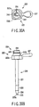
- FIG. 13A shows a seventh modification of the guide member 9 of the handpiece unit 2 according to the first embodiment (see FIGS. 1 to 6B).
- the straight portion 28 of guide member 9 is formed of, e.g. PFA, to have a thin portion.
- a deformation-promotion section 74 which tends to easily bend is formed.
- the deformation-promotion section 74 easily bend. Thereby, a large pressing force is prevented from acting on the organ H2 in the abdominal cavity.
- FIG. 13B shows an eighth modification of the guide member 9 of the handpiece unit 2 according to the first embodiment (see FIGS. 1 to 6B).
- the distal end portion of the straight portion 28 of guide member 9 is provided with, e.g. many pores 75.
- a deformation-promotion section 74 which tends to easily bend is formed.
- the deformation-promotion section 74 easily bends. Thereby, a large pressing force is prevented from acting on the organ H2 in the abdominal cavity.
- FIGS. 14A and 14B shows a fourth embodiment of the present invention.
- the structure of the handpiece unit 2 of the trocar system of the first embodiment is altered in the following fashion.
- a head 81 of the proximal end portion 22 of dilator 8 is provided with an axially extending guide groove 82.
- An operation wire 83 for pulling up the guide member 9 is passed through the guide groove 82.
- a ring 84 for hooking of the finger or the like is coupled to an outer end portion of the operation wire 83.
- a plurality of band-like index rings 91 indicative of length are axially juxtaposed on the outer periphery of the straight portion 28 of guide member 9.
- the index rings 91 provided on the distal projecting portion of the guide member 9, which projects from the breakage-prevention portion 25 of dilator 8, is viewed by the eye. Thereby, the amount of projection of the distal end portion of the guide member 9, which projects from the breakage-prevention portion 25 of dilator 8, is recognized.
- this embodiment includes the operation wire 83 for pulling up the guide member 9. With the finger or the like hooked in the ring 84 provided at the outer end of the operation wire 83, the operation wire 83 is pulled. Thereby, the guide member 9 can be pulled up. Therefore, the amount of projection of the distal end portion of the guide member 9, which projects from the distal end of dilator 8, can desirably be adjusted. In this embodiment, like the first embodiment, the amount of projection of the distal end portion of the guide member 9 can desirably be adjusted in accordance with conditions such as the thickness of the abdominal wall H that is to be pierced by the trocar tube 7, or the distance from the organ H2.
- the organ H2, etc., in the abdominal cavity will never be pressed during the dilation operation for increasing the diameter of the small-diameter pierce hole H1 made in the abdominal wall H by the trocar needle 6 up to the outside diameter of tube 7.
- the work for inserting and staying the tube 7 in the abdominal wall H can be carried out easily and quickly.
- the index rings 91 on the distal end portion of guide member 9 may be replaced with numeral indices 92 indicative of length, as shown in FIG. 14C.
- FIG. 15 shows a fifth embodiment of the invention.
- the structure of the guide member 9 of handpiece unit 2 of the first embodiment is altered in the following fashion.
- a distal end portion of the straight portion 28 of guide member 9 is provided with a bending portion 102 comprising a plurality of bending elements 101.
- the bending elements 101 are rotatably juxtaposed in the axial direction of the straight portion 28 of guide member 9.
- Each operation wire 104 for bending the bending portion 102 is passed through the guide member 9. A distal end portion of each operation wire 104 is fixed at the foremost bending element 101 of the bending portion 102.
- Two wire insertion holes 103 are formed in a proximal portion of the handle section 29 of guide member 9. A proximal end portion of each operation wire 104 is extended from the associated wire insertion hole 103 to the outside of guide member 9. An outer end portion of each operation wire 104 is connected to a ring 105 for hooking of the finger or the like.
- the operation wire 104 is pulled. Thereby, the bending of the bending portion 102 is controlled. Therefore, when the guide member 9 has been inserted in the abdominal cavity through the pierce hole H1 in the patient's abdominal wall H, the bending portion 102 at the distal end of the straight portion 28 of guide member 9 is operated so as to avoid contact with the organ H2 in the abdominal cavity.
- FIGS. 16 to 25 show a sixth embodiment of the invention.
- FIG. 16 schematically shows the entire structure of a trocar system 201 according to this embodiment.
- This trocar system 201 is provided with a handpiece unit 202 of an ultrasonic trocar, which is held and operated by the operator.
- the handpiece unit 202 is connected to an ultrasonic oscillation device 204 over a connection cable 203.
- the ultrasonic oscillation device 204 supplies energy for ultrasonic oscillation.
- the ultrasonic oscillation device 204 is connected to an output control device 205, such as a foot switch or a hand switch, for controlling energy output.
- the handpiece unit 202 of the ultrasonic trocar comprises a trocar needle 206 for piercing into the body wall; a tube 207 in which the trocar needle 206 is inserted; a dilator 208 inserted between the tube 207 and trocar needle 206; and a guide member 209 formed of a soft cylindrical member and inserted in the dilator 208.
- the guide member 209 may be formed of a hard member.
- the handpiece unit 202 of the ultrasonic trocar of this embodiment is selectively used in two modes: an assembled mode in which the trocar needle 206, tube 207, dilator 208 and guide member 209 are combined, and a disassembled mode in which these elements are separated.
- FIG. 16 shows a state in which the trocar needle 206, tube 207, dilator 208 and guide member 209 are combined.
- the trocar needle 206 is provided with a substantially straight probe 210, as shown in FIG. 17.
- a proximal-side handle 211 is disposed at a proximal end portion of the probe 210.
- the proximal-side handle 211 is provided with a substantially cylindrical housing 212.
- the housing 212 includes an ultrasonic oscillation element 213 that is an element for producing ultrasonic oscillation.
- a horn 214 for amplifying ultrasonic oscillation is disposed at a distal end portion of the ultrasonic oscillation element 213.
- a distal end portion of the horn 214 extends forward from the end of the housing 212.
- the distal end portion of the horn 214 is detachably screwed to a proximal end portion of an ultrasonic oscillation transmission rod (oscillation transmission rod) 215.
- a distal end of the oscillation transmission rod 215 is provided with a tapered pierce needle (needle body) 216.
- the pierce needle 216 is tapered, for example, in a conical shape, a trigonal pyramidal shape or a quadrangular pyramidal shape. Thereby, mechanical oscillation of the ultrasonic oscillation element 213 is transmitted to the distal-end pierce needle 216 provided at the distal end of the ultrasonic oscillation transmission rod 215.
- a guide member lock mechanism 217 (to be described later) is provided at a lower end portion of the handle 211. The guide member 209 is releasably locked by the guide member lock mechanism 217.
- the trocar tube 207 has a tubular insertion portion 219 with a relatively large diameter (e.g. about 13 mm).
- a proximal end portion 220 is provided at a proximal end of the insertion portion 219.
- a distal end portion of the insertion portion 219 has a distal bevel face 219a.
- the distal bevel face 219a is inclined to a direction perpendicular to the center axis of the insertion portion 219.
- the proximal end portion 220 has a large-diameter cylindrical portion 220a.
- An insertion guide member 220b is engaged with an opening end portion of the large-diameter cylindrical portion 220a.
- a substantially flange-shaped finger hook portion 220c is formed on the outer periphery of the large-diameter cylindrical portion 220a.
- the insertion guide member 220b is provided with a seal member 220d such as a valve (not shown), which effects sealing within the tube when an insertion instrument is inserted in the tube 207.
- a seal member 220d such as a valve (not shown), which effects sealing within the tube when an insertion instrument is inserted in the tube 207.
- the dilator 208 has a tubular insertion portion 221.
- a proximal end portion 222 is provided at a proximal end of the insertion portion 221.
- a large-diameter distal straight portion 223 for alignment is provided at a distal end of the insertion portion 221.
- the outside diameter of the distal straight portion 223 is set to be substantially equal to the inside diameter of the insertion portion 219 of tube 207.
- a distal end portion of the distal straight portion 223 is provided with a pierce hole expansion portion 224 having a substantially conical tapered shape.
- a conical distal end portion of the pierce hole expansion portion 224 is provided with a straight breakage-prevention portion 225.
- the length of the breakage-prevention portion 225 is set at a predetermined value, as measured from the conical distal end of the pierce hole expansion portion 224.
- a distal end portion of the breakage-prevention portion 225 is provided with a distal bevel face 225a.
- the distal bevel face 225a is inclined to a direction perpendicular to the center axis of the insertion portion 221.
- the proximal end portion 222 of dilator 208 includes a large-diameter cylindrical portion 222a. Over the large-diameter cylindrical portion 222a, there is provided a small-diameter cylindrical portion 222b having a smaller diameter than the cylindrical portion 222a. As is shown in FIG. 19, the inside diameter of the large-diameter cylindrical portion 222a is set to be substantially equal to the outside diameter of the large-diameter cylindrical portion 220a of trocar tube 207.
- the large-diameter cylindrical portion 222a of dilator 208 is detachably fitted on the vicinity of the opening end of the large-diameter cylindrical portion 220a of trocar tube 207.
- a proximal end portion of an operation handle 227 is screwed to the outer periphery of the large-diameter cylindrical portion 222a of dilator 208.
- a position adjusting mechanism 226 (to be described later) is provided on the small-diameter cylindrical portion 222b of dilator 208.
- the position adjusting mechanism 226 adjusts the position of the distal end of the trocar needle 206, which projects from the tube 207.
- the guide member 209 has a thin straight portion 228.
- a proximal end portion of the straight portion 228 is provided with a handle section 229.
- the straight portion 228 is formed of, e.g. Teflon (trademark): PTFE (polytetrafluoroethylene), which is a soft resin material with high heat resistance and smoothness.
- Teflon trademark: PTFE (polytetrafluoroethylene)
- the straight portion 228 is put in contact with the probe 210 that is oscillated by ultrasonic. For example, even when an inner peripheral surface of a hard metallic pipe is coated with Teflon to form a straight portion 228, the same advantage is obtained as with the resin-made straight portion 228.
- the inside diameter of the straight portion 228 is set to be substantially equal to the outside diameter of the pierce needle 216 of trocar needle 206.
- a proximal end portion of the straight portion 228 is provided with an alignment portion 228a having a diameter substantially equal to the inside diameter of the insertion portion 221 of dilator 208.
- the handle section 229 has a large-diameter cylindrical portion 230 and a small-diameter cylindrical portion 231.
- the large-diameter cylindrical portion 230 is inserted in the guide member lock mechanism 217 of trocar needle 206.
- the small-diameter cylindrical portion 231 is inserted in the position adjusting mechanism 226 of dilator 208.
- An annular first engagement groove 232 is formed in the outer periphery of large-diameter cylindrical portion 230.
- Annular second engagement grooves 233 (four in this embodiment) are formed in the outer periphery of small-diameter cylindrical portion 231 in its axial direction.
- the guide member lock mechanism 217 of trocar needle 206 is provided with a substantially cylindrical lock mechanism support member 234.
- the support member 234 is coupled to a lower end portion of the housing 212.
- a guide pin 235 and a cylindrical guide portion 236 are projected from the outer periphery of the support member 234.
- the guide pin 235 and cylindrical guide portion 236 are disposed opposed to each other at an angular distance of 180° in the circumferential direction of the lock mechanism support member 234.
- An annular lock member 218 is provided on the outer periphery of the support member 234.
- a pin insertion hole 218a in which the guide pin 235 is axially movably inserted, is formed in the outer periphery of the lock member 218.
- a lock button 237 that is projecting is screwed to the outer periphery of lock member 218.
- the lock button 237 includes an insertion hole 238.
- the guide portion 236 is axially movably inserted in the insertion hole 238.
- the lock member 218 is supported to be movable in a direction perpendicular to the axial direction of the trocar needle 206, with the guide pin 235 and guide portion 236 being used as guides.
- the lock member 218 has an inwardly projecting engagement claw 239 in the vicinity of the pin insertion hole 218a.
- the engagement claw 239 is detachably engaged in the first engagement groove 232 of guide member 209.
- a compression coil spring 240 is provided within the cylindrical guide portion 236. The spring 240 urges the engagement claw 239 in such a direction as to engage the first engagement groove 232 of guide member 209.
- the engagement claw 239 of lock member 218 is locked in the first engagement groove 232 of guide member 209, as shown in FIG. 23A, by the force of the spring 240.
- a substantially cylindrical lock mechanism support member 241 is projected on the upper side of the small-diameter cylindrical portion 222b.
- the support member 241 is coupled to the small-diameter cylindrical portion 222b of dilator 208.
- a guide pin 242 and a cylindrical guide portion 243 are projected from the outer periphery of the support member 241.
- the guide pin 242 and cylindrical guide portion 243 are disposed opposed to each other at an angular distance of 180° in the circumferential direction of support member 241.
- a substantially annular lock member 244 is provided outside the support member 241.
- a pin insertion hole 244a is formed in the outer periphery of the lock member 244.
- a guide pin 242 is axially movably inserted in the insertion hole 244a.
- a lock button (operation portion) 245, which is in a projecting state, is screwed in the pin insertion hole 244a.
- An insertion hole 246 is formed in the lock button 245.
- the cylindrical guide portion 243 is axially movably inserted in the insertion hole 246.
- the lock member 244 is supported to be movable in a direction perpendicular to the axial direction of the trocar needle 206, with the guide pin 242 and cylindrical guide portion 243 being used as guides.
- the lock button 245 is disposed opposed to the operation handle 227 of dilator 208 (at an angular distance of 180° ) with respect to the axis of the trocar needle 206.
- the lock member 244 is provided with two engagement claws 247 projecting inwards in the vicinity of the pin insertion hole 244a.
- Each engagement claw 247 is detachably engaged with one of the second engagement grooves 233 provided at a given position of guide member 209.
- a compression coil spring (urging member) 248 is provided within the cylindrical guide portion 243. The spring 248 urges the engagement claws 247 in such a direction as to engage the second engagement groove 233 of guide member 209.
- the engagement claw 247 of lock member 244 is adjusted and engaged with the uppermost second engagement groove 233 of guide member 209, the amount of projection of the trocar needle 206 projecting from the tube 207 is increased, as shown in FIG. 25A.
- the engagement claw 247 of lock member 244 is adjusted and engaged with the lowermost second engagement groove 233 of guide member 209, the amount of projection of the trocar needle 206 projecting from the tube 207 is decreased, as shown in FIG. 25B.
- the handpiece unit 202 of the ultrasonic trocar is, in advance, set in the assembled state, as shown in FIG. 16, in which the trocar needle 206, tube 207, dilator 208 and guide member 209 are combined.
- the distal end portion of the straight portion 228 of guide member 209 is projected from the breakage-prevention portion 225 of dilator 208 by a predetermined length, and is kept in this state.
- the pierce needle 216 of trocar needle 206 is projected from the distal end of the straight portion 228 of guide member 209 and kept in this state.
- the position of the distal end of the needle 206 projecting from the tube 207 can be adjusted by the position adjusting mechanism 226 of dilator 208.
- the lock member 244 moves to the right in FIG. 24B.
- the engagement claw 247 of lock member 244 is disengaged from the second engagement groove 233 of guide member 209, and the locking is released.
- the guide member 209 is axially moved relative to the dilator 208 in the unlocked state of the position adjusting mechanism 226 of dilator 208, the position of the distal end of the needle 206 projecting from the tube 207 can be adjusted.
- the engagement claw 247 of lock member 244 is adjusted and engaged with the uppermost second engagement groove 233 of guide member 209. Thereby, the amount of projection of the needle 206 projecting from the tube 207 can be increased.
- the engagement claw 247 of lock member 244 is adjusted and engaged with the lowermost second engagement groove 233 of guide member 209. Thereby, the amount of projection of the needle 206 projecting from the tube 207 can be decreased.
- the handpiece unit 202 in its assembled state as shown in FIG. 16, is operated so that the trocar tube 207 may pierce and penetrate the patient's skin and body wall and may stay therein.
- the ultrasonic oscillation device 204 is activated by the operation of the output control device 205.
- energy for ultrasonic oscillation is supplied from the ultrasonic oscillation device 204 to the ultrasonic oscillation element 213 of handpiece unit 202 over the connection cable 203.
- the ultrasonic oscillation element 213 produces ultrasonic oscillation.
- the ultrasonic oscillation produced from the ultrasonic oscillation element 213 is amplified by the horn 214 and transmitted to the ultrasonic oscillation transmission rod 215.
- the mechanical oscillation of the ultrasonic oscillation element 213 is transmitted to the pierce needle 216 of trocar needle 206 at the distal end of the ultrasonic oscillation transmission rod 215 through the horn 214.
- the pierce needle 216 of trocar needle 206 is made to pierce the patient's abdominal wall H.
- the pierce needle 216 of trocar needle 206 pierces the abdominal wall H in the state in which ultrasonic oscillation is being transmitted to the pierce needle 216 of trocar needle 206.
- the pierce needle 216 of trocar needle 206 is made to easily pierce the abdominal wall H with a weak force. With this operation, a small-diameter pierce hole H1 is made in the abdominal wall H.
- the trocar needle 206 alone is drawn out of the handpiece unit 202.
- the handpiece unit 202 is further inserted in the abdominal wall H.
- the diameter of the small-diameter pierce hole made by the trocar needle 206 is increased up to the outside diameter of the tube 207 by means of the conical portion of the pierce hole expansion portion 224 of dilator 208.
- the following operation is performed when the distal end of the guide member 209, which is projected from the distal end of the dilator 208, is in the propinquity of an organ in the abdominal cavity.
- the handle section 229 of guide member 209 is held by the fingers and the handle section 229 of guide member 209 is axially pulled from the dilator 208.
- the guide member 209 functions as a guide for the insertion of the dilator 208.
- the body wall comprises a plurality of layers.
- the pierce needle 216 Even if the pierce needle 216 has pierced the body wall, once the pierce needle 216 is pulled out of the body wall, the pierce holes in the respective layers of the body wall are displaced due to muscles. In particular, the peritoneum that is the deepest layer of the body wall may easily be displaced. If the guide member 209 is stayed in the body wall, the axis of insertion of the dilator 208 is guided by the guide member 209 while the pierce hole is being increased. This facilitates the work for increasing the diameter of the pierce hole.
- the amount of projection of the distal end portion of guide member 209, which projects from the distal end of dilator 208, is adjusted in accordance with the distance between the organ in the abdominal cavity and the distal end of straight portion 228 of guide member 209.
- the operation of axially pulling the handle section 229 of guide member 209 relative to the dilator 208 and the operation of axially pushing out the handle section 229 are properly combined.
- the amount of projection of the distal end portion of guide member 209, which projects from the distal end of dilator 208 can be adjusted as desired.
- the insertion portion 219 of trocar tube 207 is successively inserted into the pierce hole that has been enlarged by the pierce hole expansion portion 224 of dilator 208 up to a diameter substantially equal to the diameter of the insertion portion 219 of trocar tube 207.
- the insertion portion 219 of trocar tube 207 is inserted in the pierce hole in the abdominal wall H.
- the pierce hole in the abdominal wall H is dilated by the insertion operation of the insertion portion 219 of trocar tube 207.
- the insertion portion 219 of trocar tube 207 is relatively firmly fixed in the pierce hole in the abdominal wall H by the elasticity of the peripheral tissue of the pierce hole in the abdominal wall H.
- the assembly unit of the dilator 208 and guide member 209 is drawn out of the trocar tube 207.
- the trocar tube 207 is inserted and stayed in the pierce hole of abdominal wall H.
- the trocar system 201 of this embodiment includes the soft cylindrical guide member 209 projected from the distal end of the dilator 208 that is interposed between the tube 207 and trocar needle 206 in the handpiece unit 202 of the ultrasonic trocar.
- the guide member 209 can be put in contact with the organ in the abdominal cavity before the distal end portion of the dilator 208 comes in contact with the organ in the abdominal cavity. Accordingly, during the dilation operation, the distal end portion of dilator 208 is surely prevented from coming in contact with the organ in the abdominal cavity, and the safety in the dilation operation is enhanced.
- the amount of projection of the distal end portion of guide member 209, which projects from the distal end of the dilator 208, can be desirably adjusted. Accordingly, the amount of projection of the distal end portion of guide member 209 can be desirably adjusted in accordance with conditions such as the thickness of the abdominal wall H that is to be pierced by the trocar tube 207, or the distance from the organ.
- the organ in the abdominal cavity will never be pressed during the dilation operation for increasing the diameter of the small-diameter pierce hole made in the abdominal wall H by the trocar needle 206 up to the outside diameter of tube 207.
- the work for inserting and staying the tube 207 in the abdominal wall H can be carried out easily and quickly.
- the straight breakage-prevention portion 225 is provided at the distal conical end portion of the pierce hole expansion portion 224 of dilator 208.
- the conical distal portion of the pierce hole expansion portion 224 of dilator 208 is prevented from exerting a large local bending force to the guide member 209, and the guide member 209 is protected against bending.
- the breakage-prevention portion 225 of dilator 208 can be made to function also as the guide member for the dilation work.
- the operability of the dilation work of dilator 208 can be enhanced.
- the guide member lock mechanism 217 of handpiece unit 202 engages the guide member 209 in the locked state in which the engagement claw 239 of lock member 218 engages the first engagement groove 232 of guide member 209.
- the relative position of the guide member 209 and trocar needle 206 is fixed at the set position.
- the proximal end portion of tube 207 is never disengaged from the proximal end portion of the trocar needle 206.
- the operation of the trocar does not become unstable.
- the position of the distal end of trocar needle 206 projecting from the tube 207 can be adjusted, before insertion in the body wall, by the position adjusting mechanism 226.
- the amount of insertion of the distal end portion of the trocar needle 206 is adjusted, as desired, in accordance with conditions such as the thickness of the body wall for piercing or the location of piercing.
- the needle can be made to pierce the patient's body wall more efficiently in a shorter time period.
- the lock button 245 of position adjusting mechanism 226 of dilator 208 is disposed opposed to the operation handle 227 of dilator 208 (at an angular distance of 180° ) with respect to the center axis of the trocar needle 206.
- the lock button 245 is easy to handle.
- FIG. 26 shows a seventh embodiment of the present invention. This embodiment is made by altering the structure of the handpiece unit 202 of the sixth embodiment (see FIGS. 16 to 25) in the following fashion. Except for the altered portions, the handpiece unit 202 has the same structure as that in the sixth embodiment and a description thereof is omitted.
- the tube 207 has an insertion portion 219 having a relatively small diameter (e.g. about 5 mm) and a short length.
- the inside diameter of the insertion portion 219 of tube 207 is set to be substantially equal to, for example, the outside diameter of the straight portion 228 of guide member 209.
- the dilator 208 of the sixth embodiment is omitted.
- the straight portion 228 of the guide member 209 is directly inserted in the insertion portion 219 of tube 207.
- the guide member lock mechanism 217 of handpiece unit 202 engages the guide member 209 in the locked state in which the engagement claw 239 of lock member 218 engages the first engagement groove 232 of guide member 209.
- the relative position of the guide member 209 and trocar needle 206 is fixed at the set position.
- the proximal end portion of tube 207 is never disengaged from the proximal end portion of the trocar needle 206.
- the operation of the trocar does not become unstable.
- a fixing screw member 251 can detachably be engaged in the second engagement groove 233 in the outer periphery of the small-diameter cylindrical portion 231.
- a lock mechanism using an operation lever 261 may be provided.
- the present invention can provide a trocar and a trocar system wherein a tube for piercing in a patient's body can be easily and quickly inserted and stayed in the patient's skin and body wall.
Abstract
Description
- The present invention relates to a trocar and a trocar system, wherein a trocar tube, which is to be inserted in a patient's body and used as a guide tube for an instrument inserted in the body cavity, is made to stay in a state in which the tube has pierced and penetrated the patient's skin and body wall.
- In general, in the prior art, there is used a trocar apparatus wherein a trocar tube, which is to be inserted in a patient's body and used as a guide tube for an instrument inserted in the body cavity, is made to stay in a state in which the tube has pierced and penetrated the patient's skin and body wall. In the trocar apparatus, a trocar needle having a pointed pierce needle at its distal end is detachably combined with a tube having an insertion portion to be inserted in a patient.
- When the trocar apparatus is to be used, the trocar needle and the tube are integrally combined in advance. In this state, the tip end of the trocar needle is made to pierce the patient's skin, and the trocar needle and tube are made to pierce the body wall and are inserted in the body cavity. Further, after the trocar has been inserted in the body cavity, the trocar needle is drawn out of the tube and thus the tube is made to stay in the body wall. Thereby, the tube can be used as a guide tube for an optical scope or an instrument for observation and treatment of a diseased part.
- Jpn. Pat. Appln. KOKOKU Publication No. 5-57863, for instance, discloses an apparatus for inserting a trocar into the body cavity using ultrasonic oscillation. In the state in which a trocar needle and a tube are integrally combined, ultrasonic oscillation is transmitted to the trocar needle. The trocar needle, while being oscillated by ultrasonic waves, is made to pierce the patient's skin and body wall. In this case, by virtue of ultrasonic oscillation, the trocar can safely be made to pierce, and inserted in, the patient's body wall with a relatively weak force. Thus, the tube for guiding the instrument for treatment, etc. is inserted and made to stay in the body wall.
- Jpn. Pat. Appln. KOKAI Publication No. 11-89851 shows an ultrasonic trocar system with different construction. In this system, a substantially conical, tapered adapter is provided between a trocar needle with a relatively small outside diameter and a tube. The small-diameter trocar needle is used when the trocar is inserted. Thereby, the diameter of the pierce hole made by the trocar needle in the patient's body wall is decreased and the degree of invasion on the patient is reduced. Further, the tapered adapter is inserted in the pierce hole made in the body wall. The tapered adapter increases the diameter of the pierce hole made in the body wall by the trocar needle up to the outside diameter of the tube. Accordingly, the large-diameter tube can smoothly be inserted in the pierce hole in the patient's body wall.
- When the trocar needle, which is being oscillated by ultrasonic, is made to pierce the patient's skin and body wall, as disclosed in Jpn. Pat. Appln. KOKOKU Publication No. 5-57863, heat may affect the living tissue due to contact with the trocar needle that is being oscillated by ultrasonic. In order to minimize the invasion on the living tissue when the trocar needle is made to pierce the body wall, it is necessary to make the trocar needle pierce the body wall within a minimum possible time period by using the trocar needle with a relatively small outside diameter.
- In the apparatus of Jpn. Pat. Appln. KOKAI Publication No. 11-89851, the diameter of a small-diameter pierce hole is increased by a conical portion of a tapered adapter up to a relatively large outside diameter of the tube. Thus, the axial length of that portion of the tapered adapter, which projects from the distal end of the tube, is relatively long. Where the distal projecting portion of the tapered adapter is long, it is possible that while the diameter of the pierce hole is being increased by the adapter, the distal end of the adapter may come in contact with, and press, an organ in the abdominal cavity. It is thus desirable that the distal projecting portion of the adapter be made as short as possible.
- On the other hand, where the distal projecting portion of the adapter is short, it is possible that when the adapter is inserted in the pierce hole in the patient's body wall, it may not pierce the abdominal wall. In such a case, a time-consuming work is required. For example, the adapter used during the treatment has to be replaced with another adapter having a longer distal projecting portion. As a result, the time of work for inserting the tube in the body wall and staying it therein will increase.
- In the conventional trocar apparatus, the proximal end portion of the trocar needle is engaged with the proximal end portion of the tube with a relatively weak force by means of a resilient ring such as a C-ring. Consequently, when the trocar needle is made to piece the patient's body wall, the engagement between the proximal end portion of the tube and the proximal end portion of the trocar needle may be released if the user holds the trocar apparatus at an undesirable position. As a result, the operation of the trocar apparatus becomes unstable.
- Moreover, the length of the distal projecting portion of the trocar needle, which projects from the distal end of the tube, is fixed at a predetermined value. While the trocar needle is being made to pierce the patient's body wall, the amount of insertion of the distal end portion of the trocar needle is determined by the sense of the finger, the experience, etc. in accordance with conditions such as the thickness of the body wall or the location of piercing. This work is difficult and time-consuming.
- The present invention has been made in consideration of the above circumstances. An object of the invention is to provide a trocar system wherein when a small-diameter pierce hole made by a trocar needle is increased up to an outside diameter of a tube, an organ in the abdominal cavity, for instance, is not pressed and the tube can easily and quickly be inserted and stayed in the body wall.
- Another object of the invention is to provide a trocar system wherein when a small-diameter pierce hole made by a trocar needle is increased up to an outside diameter of a tube, an organ in the abdominal cavity, for instance, is not pressed and the tube can easily and quickly be inserted and stayed in the body wall, and also the work for inserting a distal end portion of the trocar needle can be easily and stably performed.
- A trocar according to the present invention comprises:
- a needle which is pierceable into a body wall;
- a tube in which the needle is insertable;
- an outer tube in which the tube is insertable and which is movable relative to the tube in the state in which the tube is inserted in the outer tube; and
- a projection portion which is a part of the tube projecting from a distal end portion of the outer tube in the state in which the tube is inserted in the outer tube, an amount of projection of the projection portion from the distal end portion of the outer tube varying in accordance with relative movement of the tube and the outer tube.
- In this invention, the amount of projection of the projection portion of the tube, which projects from the distal end of the outer tube, is adjusted. Accordingly, the amount of projection of the projection portion of the tube can be desirably adjusted in accordance with conditions such as the thickness of the body wall for piercing, or the distance from the organ in the body.
- A trocar system according to the invention comprises:
- a trocar needle which is made to pierce a body wall;
- an outer tube in which the trocar needle is inserted;
- a dilator which is interposed between the outer tube and the trocar needle and has a pierce hole expansion portion that dilates a small-diameter pierce hole made by the trocar needle; and
- a guide member which includes a cylindrical portion projecting outward from a distal end portion of the dilator and is attached to the dilator such that an amount of projection of the cylindrical portion can be varied.
- In this invention, the amount of projection of the distal end portion of the guide member, which projects outward from the distal end of the dilator interposed between the outer tube-and the trocar needle, is adjusted. Accordingly, the amount of projection of the distal end portion of the guide member can be desirably adjusted in accordance with conditions such as the thickness of the body wall for piercing, or the distance from the organ in the body.
- A trocar according to the invention comprises:
- a trocar needle which is made to pierce a body wall;
- an outer tube in which the trocar needle is inserted;
- a dilator which is interposed between the outer tube and the trocar needle and has a pierce hole expansion portion that dilates a small-diameter pierce hole made by the trocar needle; and
- a cylindrical member projecting outward from a distal end portion of the dilator,
- In this invention, the amount of projection of the distal end portion of the guide member, which projects outward from the distal end of the dilator interposed between the outer tube and the trocar needle, is adjusted. Thereby, the amount of projection of the distal end portion of the guide member can be desirably adjusted in accordance with conditions such as the thickness of the body wall for piercing, or the distance from the organ in the body. Furthermore, the position of the distal end portion of the needle, which projects from the outer tube, is adjusted in advance by the adjusting mechanism prior to the insertion in the body wall. Thereby, the amount of projection of the distal end portion of the needle projecting from the dilator can be desirably adjusted in accordance with conditions such as the thickness of the body wall for piercing, or the location for piercing.
-
- FIG. 1 is a side view of a handpiece unit, in its assembled state, of an ultrasonic trocar in a trocar system according to a first embodiment of the present invention;
- FIG. 2 is a side view showing a trocar tube, a dilator and a guide member of the ultrasonic trocar of the first embodiment;
- FIG. 3 is a side view showing an assembled unit of the trocar tube, dilator and guide member, and a trocar needle, of the ultrasonic trocar according to the first embodiment;
- FIG. 4A is a partial cross-sectional side view showing an internal structure of the assembled unit of the handpiece unit of the ultrasonic trocar according to the first embodiment;
- FIG. 4B is a vertical cross-sectional view showing a click mechanism provided between the dilator and the guide member;
- FIG. 4C is a plan view showing a seal sheet;
- FIG. 5A is a side view showing a state before the handpiece unit of the ultrasonic trocar according to the first embodiment is made to pierce the abdominal wall portion;
- FIG. 5B is a side view showing a state in which the handpiece unit of the ultrasonic trocar has pierced the abdominal wall portion;
- FIG. 5C is a side view showing a state in which the trocar needle has been drawn out of the assembly unit of the trocar apparatus;
- FIG. 6A is a side view illustrating the work for expanding the small-diameter pierce hole made by the trocar needle by means of the dilator;
- FIG. 6B is a side view showing a state in which the assembly unit comprising the dilator and guide member has been drawn out of the trocar tube;
- FIG. 7 is a side view showing a handpiece unit, in its assembled state, of an ultrasonic trocar in a trocar system according to a second embodiment of the invention;
- FIG. 8 is a partial cross-sectional side view showing an internal structure of the main part of the handpiece unit of the second embodiment;
- FIG. 9A is a side view showing a handle portion of a dilator of a handpiece unit of an ultrasonic trocar in a trocar system according to a third embodiment of the invention;
- FIG. 9B is a side view showing an upper part of the handle portion of the dilator;
- FIG. 10A is a side view showing a main part of a first modification of the dilator of the first embodiment;
- FIG. 10B is a side view showing a main part of a second modification of the dilator of the first embodiment;
- FIG. 10C is a side view showing a main part of a third modification of the dilator of the first embodiment;
- FIG. 10D is a cross-sectional view taken along line 10D-10D in FIG. 10C;
- FIG. 11A is a side view showing a main part of a first modification of the guide member of the first embodiment;
- FIG. 11B is a side view showing a main part of a second modification of the guide member of the first embodiment;
- FIG. 11C is a side view showing a main part of a third modification of the guide member of the first embodiment;
- FIG. 12A is a side view showing a main part of a fourth modification of the guide member of the first embodiment;
- FIG. 12B is a side view showing a main part of a fifth modification of the guide member of the first embodiment;
- FIG. 12C is a side view showing a main part of a sixth modification of the guide member of the first embodiment;
- FIG. 13A is a side view showing a main part of a seventh modification of the guide member of the first embodiment;
- FIG. 13B is a side view showing a main part of an eighth modification of the guide member of the first embodiment;
- FIG. 14A is a side view showing a handpiece unit, in its assembled state, of an ultrasonic trocar in a trocar system according to a fourth embodiment of the invention;
- FIG. 14B is a side view showing an example of an indication section provided at a distal end portion of the guide member;
- FIG. 14C is a side view showing another example of the indication section provided at the distal end portion of the guide member;
- FIG. 15 is a partial cross-sectional side view of a bending portion of the guide member in a trocar system according to a fifth embodiment of the invention;
- FIG. 16 is a side view showing a handpiece unit, in its assembled state, of an ultrasonic trocar in a trocar system according to a sixth embodiment of the invention;
- FIG. 17 is a side view showing the ultrasonic trocar of the sixth embodiment in its disassembled state;
- FIG. 18 is a side view showing a main part of the ultrasonic trocar of the sixth embodiment in its assembled state;
- FIG. 19 is a vertical cross-sectional view showing a main part of the ultrasonic trocar of the sixth embodiment in its assembled state;
- FIG. 20A is a plan view showing the positional relationship between the direction of the handle of the dilator and lock button in the ultrasonic trocar of the sixth embodiment;
- FIG. 20B is a side view of the dilator;
- FIG. 21 is a partial cross-sectional side view of the guide member of the ultrasonic trocar according to the sixth embodiment;
- FIG. 22 is a vertical cross-sectional view showing a peripheral structure of a guide member lock mechanism according to the sixth embodiment;
- FIG. 23A is a vertical cross-sectional view showing a main part of the guide member lock mechanism according to the sixth embodiment;
- FIG. 23B is a vertical cross-sectional view of a main part of the lock mechanism of the dilator;
- FIG. 24A is a transverse cross-sectional view showing the disengaged state of the lock mechanism of the dilator according to the sixth embodiment;
- FIG. 24B is a transverse cross-sectional view showing the engaged state of the lock mechanism;
- FIG. 25A is a side view showing the length of the distal end portion of the trocar needle according to the sixth embodiment, which is adjusted for a patient whose abdominal wall is thick;
- FIG. 25B is a side view showing the length of the distal end portion of the trocar needle, which is adjusted for a patient whose abdominal wall is thin;
- FIG. 26 is a side view showing a state in which a trocar needle of an ultrasonic trocar according to a seventh embodiment of the invention is inserted in a small-diameter tube;
- FIG. 27 is a vertical cross-sectional view showing a main part of a first modification of the lock mechanism of the dilator according to the sixth embodiment;
- FIG. 28A is a side view showing a second modification of the lock mechanism of the dilator of the sixth embodiment; and
- FIG. 28B is a plan view of the lock mechanism.
- A first embodiment of the present invention will now be described with reference to FIGS. 1 to 6B. FIG. 1 schematically shows the entire structure of a
trocar system 1 according to this embodiment. Thistrocar system 1 is provided with ahandpiece unit 2 of an ultrasonic trocar, which is held and operated by the operator. Thehandpiece unit 2 is connected to anultrasonic oscillation device 4 over aconnection cable 3. Theultrasonic oscillation device 4 supplies energy for ultrasonic oscillation. Theultrasonic oscillation device 4 is connected to an output control device 5, such as a foot switch or a hand switch, for controlling energy output. - The
handpiece unit 2 of the ultrasonic trocar comprises atrocar needle 6 for piercing into the body wall; atube 7 in which thetrocar needle 6 is inserted; adilator 8 inserted between thetube 7 andtrocar needle 6; and aguide member 9 formed of a soft cylindrical member and inserted in thedilator 8. Theguide member 9 may be formed of a hard member. Thehandpiece unit 2 of the ultrasonic trocar of this embodiment is selectively used in two modes: an assembled mode in which thetrocar needle 6,tube 7,dilator 8 and guidemember 9 are combined, and a disassembled mode in which these elements are separated. FIG. 1 shows a state in which thetrocar needle 6,tube 7,dilator 8 and guidemember 9 are combined. - The
trocar needle 6 is provided with a substantiallystraight probe 10, as shown in FIG. 3. A proximal-side handle 11 is disposed at a proximal end portion of theprobe 10. The proximal-side handle 11 is provided with a substantiallycylindrical housing 12, as shown in FIG. 4A. - The
housing 12 of thetrocar needle 6 includes anultrasonic oscillation element 13 that is an element for producing ultrasonic oscillation. Ahorn 14 for amplifying ultrasonic oscillation is disposed at a distal end portion of theultrasonic oscillation element 13. A distal end portion of thehorn 14 extends forward from the end of thehousing 12. The distal end portion of thehorn 14 is detachably screwed to a proximal end portion of an ultrasonic oscillation transmission rod (oscillation transmission rod) 15. A distal end of theoscillation transmission rod 15 is provided with a tapered pierce needle (needle body) 16. Thepierce needle 16 is tapered, for example, in a conical shape, a trigonal pyramidal shape or a quadrangular pyramidal shape. Thereby, mechanical oscillation of theultrasonic oscillation element 13 is transmitted to the distal-end pierce needle 16 provided at the distal end of the ultrasonicoscillation transmission rod 15. - A
cylindrical connection member 17 is provided at the distal side of thehousing 12. A C-ring receiving portion 18 extending inward is formed on the inner periphery of theconnection member 17. - As is shown in FIG. 2, the
trocar tube 7 has atubular insertion portion 19 with a relatively large diameter (e.g. about 13 mm). Aproximal end portion 20 is provided at a proximal end of theinsertion portion 19. - A distal end portion of the
insertion portion 19 has a distal bevel face 19a. The distal bevel face 19a is inclined to a direction perpendicular to the center axis of theinsertion portion 19. - The
proximal end portion 20 has a large-diametercylindrical portion 20a. Aninsertion guide member 20b is engaged with an opening end portion of the large-diametercylindrical portion 20a. A substantially flange-shapedfinger hook portion 20c is formed on the outer periphery of the large-diametercylindrical portion 20a. Theinsertion guide member 20b is provided with a seal member such as a valve (not shown). When an insertion instrument is inserted in thetube 7, the seal member effects sealing within the tube. - The
dilator 8 has atubular insertion portion 21. Aproximal end portion 22 is provided at a proximal end of theinsertion portion 21. A large-diameter distalstraight portion 23 for alignment is provided at a distal end of theinsertion portion 21. The outside diameter of the distalstraight portion 23 is set to be substantially equal to the inside diameter of theinsertion portion 19 oftube 7. A distal end portion of the distalstraight portion 23 is provided with a piercehole expansion portion 24 having a substantially conical tapered shape. - A conical distal end portion of the pierce
hole expansion portion 24 is provided with a straight breakage-prevention portion 25. A length S of the breakage-prevention portion 25 is set at a predetermined value, as measured from the conical distal end of the piercehole expansion portion 24. A distal end portion of the breakage-prevention portion 25 is provided with adistal bevel face 25a. Thedistal bevel face 25a is inclined to a direction perpendicular to the center axis of theinsertion portion 21. - As is shown in FIG. 4A, the
proximal end portion 22 ofdilator 8 includes a large-diametercylindrical portion 22a and a small-diametercylindrical portion 22b having a smaller diameter than thecylindrical portion 22a. The inside diameter of the large-diametercylindrical portion 22a is set to be substantially equal to the outside diameter of the large-diametercylindrical portion 20a oftrocar tube 7. The outside diameter of the small-diametercylindrical portion 22b is set to be substantially equal to the inside diameter of theconnection member 17 ofhandle 11. When thedilator 8 andtrocar tube 7 are coupled, the large-diametercylindrical portion 22a ofdilator 8 is detachably fitted on the vicinity of the opening end of the large-diametercylindrical portion 20a oftrocar tube 7. - A small-diameter connection
cylindrical portion 22c is formed on an outer periphery of a distal end portion of the small-diametercylindrical portion 22b ofdilator 8. An annular C-ring receiving groove 22d is formed in an outer periphery of the connectioncylindrical portion 22c. A C-ring 26 for engaging thetrocar needle 6 is fitted in the C-ring receiving groove 22d. The C-ring 26 is disposed at a position corresponding to the C-ring receiving portion 18 ofconnection member 17 oftrocar needle 6. When thetrocar needle 6 anddilator 8 are to be coupled, theconnection member 17 ofhousing 12 oftrocar needle 6 is fitted on the small-diametercylindrical portion 22b ofdilator 8. In this case, the C-ring 26 ofdilator 8 is detachably engaged in the C-ring receiving portion 18 oftrocar needle 6. A proximal end portion of anoperation handle 27 is screwed to the outer periphery of the large-diametercylindrical portion 22a ofdilator 8. - As is shown in FIG. 2, the
guide member 9 has a thinstraight portion 28. A proximal end portion of thestraight portion 28 is provided with ahandle section 29. Thestraight portion 28 is formed of, e.g. Teflon (trademark): PTFE (polytetrafluoroethylene), which is a soft resin material with high heat resistance and smoothness. Thestraight portion 28 is put in contact with the probe that is oscillated by ultrasonic. For example, even when an inner peripheral surface of a hard metallic pipe is coated with Teflon to form astraight portion 28, the same advantage is obtained as with the resin-madestraight portion 28. - The inside diameter of the
straight portion 28 is set to be substantially equal to the outside diameter of thepierce needle 16 oftrocar needle 6. A proximal end portion of thestraight portion 28 is provided with an alignment portion 28a having a diameter substantially equal to the inside diameter of theinsertion portion 21 ofdilator 8. - A large-diameter
seal receiving ring 30 is formed at the proximal end portion of thestraight portion 28. An annular O-ring receiving groove 30a is formed in the outer periphery ofseal receiving ring 30. A first O-ring 31 is fitted in the O-ring receiving groove 30a. When theguide member 9 is inserted in thedilator 8 for assembly, the first O-ring 31 ofguide members 9 is put in pressure contact with the inner periphery of the connectioncylindrical portion 22c ofdilator 8. Thereby, seal is effected between theseal receiving ring 30 ofguide member 9 and the connectioncylindrical portion 22c ofdilator 8. - Furthermore, as shown in FIG. 4B, an annular O-
ring receiving groove 28b is formed in the outer periphery of the alignment portion 28a ofstraight portion 28. A second O-ring 32 is fitted in the O-ring receiving groove 28b. When theguide member 9 is inserted in thedilator 8 for assembly, the second O-ring 32 ofguide member 9 is put in pressure contact with the inner periphery of theinsertion portion 21 of dilator. Thereby, seal is effected between the outer periphery of the alignment portion 28a ofguide member 9 and the inner periphery of theinsertion portion 21 ofdilator 8. - A plurality (three in the embodiment) of O-
ring engagement grooves 21a, 21b and 21c are formed in the inner periphery of the insertion portion ofdilator 8. The O-ring engagement grooves 21a, 21b and 21c are provided in the direction of insertion of theguide member 9. The interval between O-ring engagement grooves 21a and 21b and the interval between O-ring engagement grooves 21b and 21c are set at about 10 mm, respectively. When theguide member 9 is drawn out of theinsertion portion 21 ofdilator 8, the second O-ring 32 ofguide member 9 is detachably engaged with the O-ring engagement grooves 21a, 21b and 21c in succession. Thus, when theguide member 9 is drawn out of theinsertion portion 21 ofdilator 8, the user can sense a click and recognize the amount of draw-out of theguide member 9 without observation by the naked eye. - The O-
ring engagement groove 21c is disposed at that area of theinsertion portion 21 ofdilator 8, which corresponds to the final position in the draw-out direction of theguide member 9. A diameter d1 of this O-ring engagement groove 21c is less than a diameter d of each of the other O-ring engagement grooves 21a and 21b (d1 < d). Thus, the O-ring engagement groove 21c is formed to have the least depth. - As a result, when the
guide member 9 is drawn out of theinsertion portion 21 ofdilator 8, the intensity of operational sensation, i.e. the sensation of engagement, which is felt when the second O-ring 32 ofguide member 9 is engaged with the O-ring engagement groove 21c, is made greater than that obtained when the second O-ring 32 is engaged with the other O-ring engagement grooves 21a, 21b. Thereby, the draw-out position of theguide member 9 can recognized more exactly by sensation. This also prevents unintentional draw-out of the guide member. - The
handle section 29 ofguide member 9 includes ahandle portion 33. Thehandle portion 33 is formed to have a substantially truncated-conical cross section. As is shown in FIG. 4A, a small-diameter end portion of thehandle portion 33 is screwed to the inner periphery of theseal receiving ring 30. A tapered outer periphery of thehandle portion 33 is subject to non-slip treatment (not shown). - The inner periphery of the
seal receiving ring 30 is provided with a steppedseal receiving portion 30b. As is shown in FIG. 4C, a circular air-tight seal member 34 is disposed at theseal receiving portion 30b. Theseal member 34 is, e.g. a rubber sheet. Theseal member 34 is clamped and fixed between theseal receiving portion 30b ofseal receiving ring 30 and the small-diameter end portion ofhandle portion 33. A slit 34a is formed in a central portion of theseal member 34. The slit 34a has a substantially straight shape. When thetrocar system 1 of this embodiment is used, theguide member 9 is inserted and assembled in theinsertion portion 21 ofdilator 8, as shown in FIG. 3. In this case, the distal end portion of thestraight portion 28 ofguide member 9 is held in the state in which it is projected from the breakage-prevention portion 25 ofdilator 8 by a predetermined length. In this state, thehandle section 29 ofguide member 9 is held by the fingers, and the operation of axially pulling thehandle section 29 ofguide member 9 relative to thedilator 8 and the operation of pushing it are properly combined. Thereby, the amount of projection of the distal end portion ofguide member 9, which projects from the distal end of thedilator 8, can be adjusted as desired. - The operation of the above-described structure will now be described. When the
trocar system 1 of this embodiment is to be used, thehandpiece unit 2 of the ultrasonic trocar is, in advance, set in the assembled state, as shown in FIG. 1, in which thetrocar needle 6,tube 7,dilator 8 and guidemember 9 are combined. At this time, the distal end portion of thestraight portion 28 ofguide member 9 is projected from the breakage-prevention portion 25 ofdilator 8 by a predetermined length, and is kept in this state. In addition, thepierce needle 16 oftrocar needle 6 is projected from the distal end of thestraight portion 28 ofguide member 9 and kept in this state. - The
handpiece unit 2, in its assembled state as shown in FIG. 1, is operated so that thetrocar tube 7 may pierce and penetrate the patient's skin and body wall and may stay therein. At the time of the piercing operation of thehandpiece unit 2, theultrasonic oscillation device 4 is activated by the operation of the output control device 5. At this time, energy for ultrasonic oscillation is supplied from theultrasonic oscillation device 4 to theultrasonic oscillation element 13 ofhandpiece unit 2 over theconnection cable 3. Thus, theultrasonic oscillation element 13 produces ultrasonic oscillation. The ultrasonic oscillation produced from theultrasonic oscillation element 13 is amplified by thehorn 14 and transmitted to the ultrasonicoscillation transmission rod 15. Thus, the mechanical oscillation of theultrasonic oscillation element 13 is transmitted to thepierce needle 16 oftrocar needle 6 at the distal end of the ultrasonicoscillation transmission rod 15 through thehorn 14. - Then, with the
handpiece unit 2 being held, thepierce needle 16 oftrocar needle 6 is made to pierce the patient's abdominal wall H, as shown in FIG. 5A. At this time, thepierce needle 16 oftrocar needle 6 pierces the abdominal wall H in the state in which ultrasonic oscillation is being transmitted to thepierce needle 16 oftrocar needle 6. Thus, thepierce needle 16 oftrocar needle 6 is made to easily pierce the abdominal wall H with a weak force. With this operation, as shown in FIG. 5B, a small-diameter pierce hole H1 is made in the abdominal wall H. - As is shown in FIG. 5B, after the
handpiece unit 2 has been inserted up to the location of the breakage-prevention portion 25 near the piercehole expansion portion 24 ofdilator 8, thetrocar needle 6 alone is drawn out of thehandpiece unit 2. In this state, thehandpiece unit 2 is further inserted in the abdominal wall H. Thereby, as shown in FIG. 5C, the diameter of the small-diameter pierce hole H1 made by thetrocar needle 6 is increased up to the outside diameter of thetube 7 by means of the conical portion of the piercehole expansion portion 24 ofdilator 8. - Prior to the work for increasing the diameter of the pierce hole H1, the following operation is performed when the distal end of the
guide member 9, which is projected from the distal end of thedilator 8, is in the propinquity of an organ H2 in the abdominal cavity. Specifically, thehandle section 29 ofguide member 9 is held by the fingers and thehandle section 29 ofguide member 9 is axially pulled from thedilator 8. Thereby, the amount of projection of the distal end portion of theguide member 9, which projects from the distal end of thedilator 8, is decreased. At this time, theguide member 9 functions as a guide for the insertion of thedilator 8. In general terms, the body wall comprises a plurality of layers. Even if thepierce needle 16 has pierced the body wall, once thepierce needle 16 is pulled out of the body wall, the pierce holes in the respective layers of the body wall are displaced due to muscles. In particular, the peritoneum that is the deepest layer of the body wall may easily be displaced. If theguide member 9 is stayed in the body wall, the axis of insertion of thedilator 8 is guided by theguide member 9 while the pierce hole is being increased. This facilitates the work for increasing the diameter of the pierce hole. - In addition, while the diameter of the pierce hole H1 is being increased, the amount of projection of the distal end portion of
guide member 9, which projects from the distal end ofdilator 8, is adjusted in accordance with the distance between the organ H2 in the abdominal cavity and the distal end ofstraight portion 28 ofguide member 9. In this work of adjusting the projection amount ofguide member 9, the operation of axially pulling thehandle section 29 ofguide member 9 relative to thedilator 8 and the operation of axially pushing out thehandle section 29 are properly combined. Thereby, the amount of projection of the distal end portion ofguide member 9, which projects from the distal end ofdilator 8, can be adjusted as desired. - When the diameter of the pierce hole H1 is to be increased, the operation of pushing the
handpiece unit 2 into the abdominal wall H and the operation of rotating it about the center axis of thetrocar tube 7, as indicated by an arrow in FIG. 6A, are simultaneously performed while the operation handle 27 ofdilator 8 and thefinger hook portion 20c oftrocar tube 7 are being held. Thereby, with the operation of pushing the conical portion of the piercehole expansion portion 24, the work for increasing the diameter of the small-diameter pierce hole H1 up to the outside diameter oftube 7 is performed. At the time of this work,- theinsertion portion 19 oftrocar tube 7 is successively inserted into the pierce hole H1 that has been enlarged by the piercehole expansion portion 24 ofdilator 8 up to a diameter substantially equal to the diameter of theinsertion portion 19 oftrocar tube 7. Thus, theinsertion portion 19 oftrocar tube 7 is inserted in the pierce hole H1. - Once the
insertion portion 19 oftrocar tube 7 has been inserted in the pierce hole H1, theinsertion portion 19 oftrocar tube 7 is relatively firmly fixed in the pierce hole H1 in the abdominal wall H by the elasticity of the peripheral tissue of the pierce hole H1 enlarged by the insertion of theinsertion portion 19. In this state, as shown in FIG. 6B, the assembly unit of thedilator 8 and guidemember 9 is drawn out of thetrocar tube 7. Thus, thetrocar tube 7 is inserted and stayed in the pierce hole H1 of abdominal wall H. - With the above structure, the following advantages can be obtained. The
trocar system 1 of this embodiment includes the softcylindrical guide member 9 projected from the distal end of thedilator 8 that is interposed between thetube 7 andtrocar needle 6. Thus, when the small-diameter pierce hole H1 made by thetrocar needle 6 is to be enlarged up to the outside diameter of thetube 7 by the conical portion of the piercehole expansion portion 24 ofdilator 8, theguide member 9 can be put in contact with the organ H2 in the abdominal cavity before the distal end portion of thedilator 8 comes in contact with the organ H2 in the abdominal cavity. Accordingly, during the dilation operation, the distal end portion ofdilator 8 is surely prevented from coming in contact with the organ H2 in the abdominal cavity, and the safety in the dilation operation is enhanced. - While the
handle section 29 ofguide member 9 is being held by the fingers, the operation of axially pulling thehandle section 29 ofguide member 9 relative to thedilator 8 and the operation of pushing it out are properly combined. Thereby, the amount of projection of the distal end portion ofguide member 9, which projects from the distal end of thedilator 8, can be desirably adjusted. Accordingly, the amount of projection of the distal end portion ofguide member 9 can be desirably adjusted in accordance with conditions such as the thickness of the abdominal wall H that is to be pierced by thetrocar tube 7, or the distance from the organ H2. As a result, the organ H2 in the abdominal cavity will never be pressed during the dilation operation for increasing the diameter of the small-diameter pierce hole H1 made in the abdominal wall H by thetrocar needle 6 up to the outside diameter oftube 7. Moreover, the work for inserting and staying thetube 7 in the abdominal wall H can be carried out easily and quickly. - The straight breakage-
prevention portion 25 is provided at the distal conical end portion of the piercehole expansion portion 24 ofdilator 8. Thus, when a lateral force acts on thesoft guide member 9 projecting from the distal end ofdilator 8, the force acting in such a direction as to bend theguide member 9 at the distal conical portion of the piercehole expansion hole 24 ofdilator 8 can be dispersed over the wide area of the straight breakage-prevention section 25 ofdilator 8. Accordingly, the conical distal portion of the piercehole expansion portion 24 ofdilator 8 is prevented from exerting a large local bending force to theguide member 9, and theguide member 9 is protected against bending. - During the dilation operation, the breakage-
prevention portion 25 ofdilator 8 can be made to function also as the guide member for the dilation work. Thus, the operability of the dilation work ofdilator 8 can be enhanced. - In the present embodiment, the second O-
ring 32 is fitted on the outer periphery of the alignment portion 28a ofguide member 9. Further, the three O-ring engagement grooves 21a, 21b and 21c are formed in the inner periphery of theinsertion portion 21 ofdilator 8 in the direction of insertion of theguide member 9. When theguide member 9 is pulled from theinsertion portion 21 ofdilator 8, the second O-ring 32 ofguide member 9 is detachably engaged with the O-ring engagement grooves 21a, 21b and 21c in succession. Accordingly, when theguide member 9 is drawn out of theinsertion portion 21 ofdilator 8, the user can sense a click and recognize the amount of draw-out of theguide member 9 by sensing. As a result, the amount of projection of the distal end portion ofguide member 9, which cannot directly be observed by the naked eye, can easily be recognized. - FIGS. 7 and 8 show a second embodiment of the present invention. This embodiment is made by altering the structure of the
handpiece unit 2 of the trocar system of the first embodiment (see FIGS. 1 to 6B) in the following fashion. Except for the altered portions, thehandpiece unit 2 has the same structure as that in the first embodiment and a description thereof is omitted. - Specifically, in this embodiment, the
tube 7 has theinsertion portion 19 having a relatively small diameter (e.g. about 5 mm) and a short length. The inside diameter of theinsertion portion 19 oftube 7 is set to be substantially equal to, for example, the outside diameter of thestraight portion 28 ofguide member 9. In this embodiment, thedilator 8 of the first embodiment is omitted. As shown in FIG. 7, thestraight portion 28 of theguide member 9 is directly inserted in theinsertion portion 19 oftube 7. - Furthermore, in this embodiment, a
cylindrical spacer 41 for wavelength adjustment of ultrasonic oscillation is provided between theproximal end portion 20 oftube 7 and thehandle 11 oftrocar needle 6. As is shown in FIG. 8, a small-diameter trocarneedle coupling portion 42 is provided at one of thespacer 41. Theconnection member 17 oftrocar needle 6 is detachably fitted on thecoupling portion 42. - A small-diameter
cylindrical portion 43 is provided at the distal end of thecoupling portion 42 ofspacer 41. An annular C-ring receiving groove 44 is formed in the outer periphery of the small-diametercylindrical portion 43. A C-ring 45 for engaging thetrocar needle 6 is fitted in the receivinggroove 44. The C-ring 45 is disposed at a position corresponding to the C-ring receiving portion 18 ofconnection member 17 oftrocar needle 6. When thetrocar needle 6 andspacer 41 are to be coupled, theconnection member 17 oftrocar needle 6 is fitted on thecoupling portion 42 ofspacer 41. In this state, the C-ring 45 of trocarneedle coupling portion 42 is detachably engaged in the C-ring receiving portion 18 oftrocar needle 6 to prevent disengagement. - When the
guide member 9 is inserted in thetube 7 for assembly, the first O-ring 31 ofguide member 9 is pressed on the inner periphery of the small-diametercylindrical portion 43 ofspacer 41. Thus, seal is effected between theseal receiving ring 30 and the small-diametercylindrical portion 43 ofspacer 41. - The embodiment with the above-described structure has the following advantages. In this embodiment, the
cylindrical spacer 41 for wavelength adjustment of ultrasonic oscillation is provided between theproximal end portion 20 oftube 7 and thehandle 11 oftrocar needle 6. Thereby, the length of thespacer 41 can be adjusted in accordance with the oscillation characteristics of the ultrasonic oscillation produced by theultrasonic oscillation element 13 and transmitted to theprobe 10 oftrocar needle 6. Even in the case of using a model wherein the diameter of theinsertion portion 19 oftube 7 is relatively small and the length thereof is small, the length of thespacer 41 may be adjusted. Thus, like the first embodiment wherein thedilator 8 is interposed between thetube 7 andtrocar needle 6, thehandpiece unit 2 of the ultrasonic trocar can perform ultrasonic treatment. - FIGS. 9A and 9B show a third embodiment of the present invention. This embodiment is made by altering the structure of the
dilator 8 ofhandpiece unit 2 of the trocar system of the first embodiment (see FIGS. 1 to 6B) in the following fashion. Except for the altered portions, thehandpiece unit 2 has the same structure as that in the first embodiment and a description thereof is omitted. - Specifically, in this embodiment, a plurality of models wherein the small-diameter
cylindrical portions 22b ofproximal end portions 22 ofdilators 8 have different lengths L1 are prepared in advance. For example, a model with a smaller axial length L1 of the small-diametercylindrical portion 22b, as shown in FIG. 9A, and a model with a greater axial length L1 of a small-diametercylindrical portion 51, as shown in FIG. 9B, are prepared in advance. In accordance with the length of theinsertion portion 19 oftrocar tube 7, thedilator 8 with a proper length L1 of the small-diametercylindrical portion - In this embodiment, in accordance with the variation in conditions, such as the length of the
insertion portion 19 oftrocar tube 7, thedilator 8 with a proper axial length L1 of the small-diametercylindrical portion hole expansion portion 24 ofdilator 8 can properly be adjusted. - FIG. 10A shows a first modification of the
dilator 8 of thehandpiece unit 2 according to the first embodiment (see FIGS. 1 to 6B). In this modification, the distal end portion of the breakage-prevention portion 25 ofdilator 8 is provided with aflat face 25b formed in a direction perpendicular to the center axis of theinsertion portion 21. In addition, in this modification, the length of the breakage-prevention portion 25 ofdilator 8 is set to be less than the length S of the breakage-prevention portion 25 ofdilator 8 in the first embodiment. Thedilator 8 of this modification can be used similarly with the first embodiment. - FIG. 10B shows a second modification of the
dilator 8 of thehandpiece unit 2 according to the first embodiment (see FIGS. 1 to 6B). In this modification, the tapered surface of the piercehole expansion portion 24 has threadedgrooves 52. In this case, when the pierce hole H1 is dilated by the piercehole expansion portion 24 ofdilator 8, the piercehole expansion portion 24 ofdilator 8 is rotated. Thereby, the operation for enlarging the pierce hole H1 can be promoted by the threadedgrooves 52 in the tapered surface of the piercehole expansion portion 24. - FIGS. 10C and 10D show a third modification of the
dilator 8 of thehandpiece unit 2 according to the first embodiment (see FIGS. 1 to 6B). In this modification, the tapered surface of the piercehole expansion portion 24 is provided with twoprojections 53. The twoprojections 53 extend in the axial direction on the tapered surface of the piercehole expansion portion 24. In this case, when the pierce hole H1 is to be enlarged by the piercehole expansion portion 24 ofdilator 8, the piercehole expansion portion 24 ofdilator 8 can be axially pushed out while the rotation of thedilator 8 is prevented by the twoprojections 53. Therefore, in this modification, compared to the case of rotating thedilator 8, the pierce hole H1 can be more easily enlarged. In addition, twisting of the peripheral part of the pierce hole H1 due to rotation ofdilator 8 can be prevented. - FIG. 11A shows a first modification of the
guide member 9 of thehandpiece unit 2 according to the first embodiment (see FIGS. 1 to 6B). In this modification, thehandle section 29 ofguide member 9 is provided with a colored line 61. When theguide member 9 is drawn out of thedilator 8, the line 61 on thehandle portion 29 ofguide member 9 is viewed by the eye and the amount of projection of theguide member 9 is indicated. - FIG. 11B shows a second modification of the
guide member 9 of thehandpiece unit 2 according to the first embodiment (see FIGS. 1 to 6B). In this modification, thehandle section 29 ofguide member 9 is provided with aclick mechanism 62. When theguide member 9 is drawn out of thedilator 8, the amount of draw-out of theguide member 9 is indicated by the sensing obtained by the operation of theclick mechanism 62. - FIG. 11C shows a third modification of the
guide member 9 of thehandpiece unit 2 according to the first embodiment (see FIGS. 1 to 6B). In this modification, thehandle section 29 ofguide member 9 is provided with a whistle-shaped portion 63 that produces an air leak sound. When theguide member 9 is drawn out of thedilator 8, an air leak sound produced through the whistle-shaped portion 63 ofhandle section 29 ofguide member 9 is heard and the amount of draw-out of theguide member 9 is indicated. - FIG. 12A shows a fourth modification of the
guide member 9 of thehandpiece unit 2 according to the first embodiment (see FIGS. 1 to 6B). In this modification, the distal end portion of thestraight portion 28 ofguide member 9 is provided with a reformed bending portion 71 curved away from the center axis of thestraight portion 28. In this modification, when theguide member 9 has been inserted in the abdominal cavity through the pierce hole H1 in the patient's abdominal wall H, the bending portion 71 at the distal end of thestraight portion 28 ofguide member 9 is curved away from the center axis of thestraight portion 28. Thereby, contact with the organ H2 in the abdominal cavity can be avoided. - FIG. 12B shows a fifth modification of the
guide member 9 of thehandpiece unit 2 according to the first embodiment (see FIGS. 1 to 6B). In this modification, the distal end portion of thestraight portion 28 ofguide member 9 is provided with a bellows-shapedextensible portion 72. In this modification, when theguide member 9 has been inserted in the abdominal cavity through the pierce hole H1 in the patient's abdominal wall H and the distal end of thestraight portion 28 ofguide member 9 has come in contact with the organ H2 in the abdominal cavity, theextensible portion 72 easily contracts. Thereby, a large pressing force is prevented from acting on the organ H2 in the abdominal cavity. - FIG. 12C shows a sixth modification of the
guide member 9 of thehandpiece unit 2 according to the first embodiment (see FIGS. 1 to 6B). In this modification, the distal end portion of thestraight portion 28 ofguide member 9 is provided with anaxially extending slit 73. In this modification, when theguide member 9 has been inserted in the abdominal cavity through the pierce hole H1 in the patient's abdominal wall H and the distal end of thestraight portion 28 ofguide member 9 has come in contact with the organ H2 in the abdominal cavity, the surrounding portion of theslit 73 of thestraight portion 28 expands to both lateral sides and contracts by a proper length L3. Thereby, a large pressing force is prevented from acting on the organ H2 in the abdominal cavity. - FIG. 13A shows a seventh modification of the
guide member 9 of thehandpiece unit 2 according to the first embodiment (see FIGS. 1 to 6B). In this modification, thestraight portion 28 ofguide member 9 is formed of, e.g. PFA, to have a thin portion. Thus, a deformation-promotion section 74 which tends to easily bend is formed. In this modification, when theguide member 9 has been inserted in the abdominal cavity through the pierce hole H1 in the patient's abdominal wall H and the distal end of thestraight portion 28 ofguide member 9 has come in contact with the organ H2 in the abdominal cavity, the deformation-promotion section 74 easily bend. Thereby, a large pressing force is prevented from acting on the organ H2 in the abdominal cavity. - FIG. 13B shows an eighth modification of the
guide member 9 of thehandpiece unit 2 according to the first embodiment (see FIGS. 1 to 6B). In this modification, the distal end portion of thestraight portion 28 ofguide member 9 is provided with, e.g. many pores 75. Thus, a deformation-promotion section 74 which tends to easily bend is formed. In this modification, when theguide member 9 has been inserted in the abdominal cavity through the pierce hole H1 in the patient's abdominal wall H and the distal end of thestraight portion 28 ofguide member 9 has come in contact with the organ H2 in the abdominal cavity, the deformation-promotion section 74 easily bends. Thereby, a large pressing force is prevented from acting on the organ H2 in the abdominal cavity. - FIGS. 14A and 14B shows a fourth embodiment of the present invention. In this embodiment, the structure of the
handpiece unit 2 of the trocar system of the first embodiment (see FIGS. 1 to 6B) is altered in the following fashion. - In this embodiment, as shown in FIG. 14A, a
head 81 of theproximal end portion 22 ofdilator 8 is provided with an axially extendingguide groove 82. Anoperation wire 83 for pulling up theguide member 9 is passed through theguide groove 82. Aring 84 for hooking of the finger or the like is coupled to an outer end portion of theoperation wire 83. - As is shown in FIG. 14B, a plurality of band-like index rings 91 indicative of length are axially juxtaposed on the outer periphery of the
straight portion 28 ofguide member 9. For example, when an endoscopic image of the abdominal cavity is observed, the index rings 91 provided on the distal projecting portion of theguide member 9, which projects from the breakage-prevention portion 25 ofdilator 8, is viewed by the eye. Thereby, the amount of projection of the distal end portion of theguide member 9, which projects from the breakage-prevention portion 25 ofdilator 8, is recognized. - The embodiment with the above structure has the following advantages. Specifically, this embodiment includes the
operation wire 83 for pulling up theguide member 9. With the finger or the like hooked in thering 84 provided at the outer end of theoperation wire 83, theoperation wire 83 is pulled. Thereby, theguide member 9 can be pulled up. Therefore, the amount of projection of the distal end portion of theguide member 9, which projects from the distal end ofdilator 8, can desirably be adjusted. In this embodiment, like the first embodiment, the amount of projection of the distal end portion of theguide member 9 can desirably be adjusted in accordance with conditions such as the thickness of the abdominal wall H that is to be pierced by thetrocar tube 7, or the distance from the organ H2. As a result, the organ H2, etc., in the abdominal cavity will never be pressed during the dilation operation for increasing the diameter of the small-diameter pierce hole H1 made in the abdominal wall H by thetrocar needle 6 up to the outside diameter oftube 7. Moreover, the work for inserting and staying thetube 7 in the abdominal wall H can be carried out easily and quickly. - In the fourth embodiment (see FIGS. 14A and 14B), the index rings 91 on the distal end portion of
guide member 9 may be replaced withnumeral indices 92 indicative of length, as shown in FIG. 14C. - FIG. 15 shows a fifth embodiment of the invention. In this embodiment, the structure of the
guide member 9 ofhandpiece unit 2 of the first embodiment (see FIGS. 1 to 6B) is altered in the following fashion. - In this embodiment, a distal end portion of the
straight portion 28 ofguide member 9 is provided with a bendingportion 102 comprising a plurality of bendingelements 101. In this bendingportion 102, the bendingelements 101 are rotatably juxtaposed in the axial direction of thestraight portion 28 ofguide member 9. - Two
operation wires 104 for bending the bendingportion 102 are passed through theguide member 9. A distal end portion of eachoperation wire 104 is fixed at theforemost bending element 101 of the bendingportion 102. - Two wire insertion holes 103 are formed in a proximal portion of the
handle section 29 ofguide member 9. A proximal end portion of eachoperation wire 104 is extended from the associatedwire insertion hole 103 to the outside ofguide member 9. An outer end portion of eachoperation wire 104 is connected to aring 105 for hooking of the finger or the like. - In this embodiment, with the finger or the like hooked in the
ring 105 provided at the outer end of theoperation wire 104, theoperation wire 104 is pulled. Thereby, the bending of the bendingportion 102 is controlled. Therefore, when theguide member 9 has been inserted in the abdominal cavity through the pierce hole H1 in the patient's abdominal wall H, the bendingportion 102 at the distal end of thestraight portion 28 ofguide member 9 is operated so as to avoid contact with the organ H2 in the abdominal cavity. - FIGS. 16 to 25 show a sixth embodiment of the invention. FIG. 16 schematically shows the entire structure of a
trocar system 201 according to this embodiment. Thistrocar system 201 is provided with ahandpiece unit 202 of an ultrasonic trocar, which is held and operated by the operator. Thehandpiece unit 202 is connected to anultrasonic oscillation device 204 over aconnection cable 203. Theultrasonic oscillation device 204 supplies energy for ultrasonic oscillation. Theultrasonic oscillation device 204 is connected to anoutput control device 205, such as a foot switch or a hand switch, for controlling energy output. - The
handpiece unit 202 of the ultrasonic trocar comprises atrocar needle 206 for piercing into the body wall; atube 207 in which thetrocar needle 206 is inserted; adilator 208 inserted between thetube 207 andtrocar needle 206; and aguide member 209 formed of a soft cylindrical member and inserted in thedilator 208. Theguide member 209 may be formed of a hard member. Thehandpiece unit 202 of the ultrasonic trocar of this embodiment is selectively used in two modes: an assembled mode in which thetrocar needle 206,tube 207,dilator 208 and guidemember 209 are combined, and a disassembled mode in which these elements are separated. FIG. 16 shows a state in which thetrocar needle 206,tube 207,dilator 208 and guidemember 209 are combined. - The
trocar needle 206 is provided with a substantiallystraight probe 210, as shown in FIG. 17. A proximal-side handle 211 is disposed at a proximal end portion of theprobe 210. The proximal-side handle 211 is provided with a substantiallycylindrical housing 212. - As is shown in FIG. 19, the
housing 212 includes anultrasonic oscillation element 213 that is an element for producing ultrasonic oscillation. Ahorn 214 for amplifying ultrasonic oscillation is disposed at a distal end portion of theultrasonic oscillation element 213. A distal end portion of thehorn 214 extends forward from the end of thehousing 212. The distal end portion of thehorn 214 is detachably screwed to a proximal end portion of an ultrasonic oscillation transmission rod (oscillation transmission rod) 215. A distal end of theoscillation transmission rod 215 is provided with a tapered pierce needle (needle body) 216. Thepierce needle 216 is tapered, for example, in a conical shape, a trigonal pyramidal shape or a quadrangular pyramidal shape. Thereby, mechanical oscillation of theultrasonic oscillation element 213 is transmitted to the distal-end pierce needle 216 provided at the distal end of the ultrasonicoscillation transmission rod 215. A guide member lock mechanism 217 (to be described later) is provided at a lower end portion of thehandle 211. Theguide member 209 is releasably locked by the guidemember lock mechanism 217. - As is shown in FIG. 17, the
trocar tube 207 has atubular insertion portion 219 with a relatively large diameter (e.g. about 13 mm). Aproximal end portion 220 is provided at a proximal end of theinsertion portion 219. A distal end portion of theinsertion portion 219 has adistal bevel face 219a. Thedistal bevel face 219a is inclined to a direction perpendicular to the center axis of theinsertion portion 219. Theproximal end portion 220 has a large-diametercylindrical portion 220a. Aninsertion guide member 220b is engaged with an opening end portion of the large-diametercylindrical portion 220a. A substantially flange-shapedfinger hook portion 220c is formed on the outer periphery of the large-diametercylindrical portion 220a. - As is shown in FIG. 19, the
insertion guide member 220b is provided with aseal member 220d such as a valve (not shown), which effects sealing within the tube when an insertion instrument is inserted in thetube 207. - As is shown in FIG. 20B, the
dilator 208 has atubular insertion portion 221. Aproximal end portion 222 is provided at a proximal end of theinsertion portion 221. A large-diameter distalstraight portion 223 for alignment is provided at a distal end of theinsertion portion 221. The outside diameter of the distalstraight portion 223 is set to be substantially equal to the inside diameter of theinsertion portion 219 oftube 207. A distal end portion of the distalstraight portion 223 is provided with a piercehole expansion portion 224 having a substantially conical tapered shape. - A conical distal end portion of the pierce
hole expansion portion 224 is provided with a straight breakage-prevention portion 225. The length of the breakage-prevention portion 225 is set at a predetermined value, as measured from the conical distal end of the piercehole expansion portion 224. A distal end portion of the breakage-prevention portion 225 is provided with adistal bevel face 225a. Thedistal bevel face 225a is inclined to a direction perpendicular to the center axis of theinsertion portion 221. - The
proximal end portion 222 ofdilator 208 includes a large-diametercylindrical portion 222a. Over the large-diametercylindrical portion 222a, there is provided a small-diametercylindrical portion 222b having a smaller diameter than thecylindrical portion 222a. As is shown in FIG. 19, the inside diameter of the large-diametercylindrical portion 222a is set to be substantially equal to the outside diameter of the large-diametercylindrical portion 220a oftrocar tube 207. When thedilator 208 andtrocar tube 207 are coupled, the large-diametercylindrical portion 222a ofdilator 208 is detachably fitted on the vicinity of the opening end of the large-diametercylindrical portion 220a oftrocar tube 207. A proximal end portion of anoperation handle 227 is screwed to the outer periphery of the large-diametercylindrical portion 222a ofdilator 208. - A position adjusting mechanism 226 (to be described later) is provided on the small-diameter
cylindrical portion 222b ofdilator 208. Theposition adjusting mechanism 226 adjusts the position of the distal end of thetrocar needle 206, which projects from thetube 207. - As is shown in FIG. 21, the
guide member 209 has a thinstraight portion 228. A proximal end portion of thestraight portion 228 is provided with ahandle section 229. Thestraight portion 228 is formed of, e.g. Teflon (trademark): PTFE (polytetrafluoroethylene), which is a soft resin material with high heat resistance and smoothness. Thestraight portion 228 is put in contact with theprobe 210 that is oscillated by ultrasonic. For example, even when an inner peripheral surface of a hard metallic pipe is coated with Teflon to form astraight portion 228, the same advantage is obtained as with the resin-madestraight portion 228. - The inside diameter of the
straight portion 228 is set to be substantially equal to the outside diameter of thepierce needle 216 oftrocar needle 206. A proximal end portion of thestraight portion 228 is provided with analignment portion 228a having a diameter substantially equal to the inside diameter of theinsertion portion 221 ofdilator 208. - The
handle section 229 has a large-diametercylindrical portion 230 and a small-diametercylindrical portion 231. The large-diametercylindrical portion 230 is inserted in the guidemember lock mechanism 217 oftrocar needle 206. The small-diametercylindrical portion 231 is inserted in theposition adjusting mechanism 226 ofdilator 208. An annularfirst engagement groove 232 is formed in the outer periphery of large-diametercylindrical portion 230. Annular second engagement grooves 233 (four in this embodiment) are formed in the outer periphery of small-diametercylindrical portion 231 in its axial direction. - As is shown in FIG. 23A, the guide
member lock mechanism 217 oftrocar needle 206 is provided with a substantially cylindrical lockmechanism support member 234. Thesupport member 234 is coupled to a lower end portion of thehousing 212. Aguide pin 235 and acylindrical guide portion 236 are projected from the outer periphery of thesupport member 234. Theguide pin 235 andcylindrical guide portion 236 are disposed opposed to each other at an angular distance of 180° in the circumferential direction of the lockmechanism support member 234. - An
annular lock member 218 is provided on the outer periphery of thesupport member 234. Apin insertion hole 218a, in which theguide pin 235 is axially movably inserted, is formed in the outer periphery of thelock member 218. In addition, alock button 237 that is projecting is screwed to the outer periphery oflock member 218. Thelock button 237 includes aninsertion hole 238. Theguide portion 236 is axially movably inserted in theinsertion hole 238. Thelock member 218 is supported to be movable in a direction perpendicular to the axial direction of thetrocar needle 206, with theguide pin 235 andguide portion 236 being used as guides. - The
lock member 218 has an inwardly projectingengagement claw 239 in the vicinity of thepin insertion hole 218a. Theengagement claw 239 is detachably engaged in thefirst engagement groove 232 ofguide member 209. In addition, acompression coil spring 240 is provided within thecylindrical guide portion 236. Thespring 240 urges theengagement claw 239 in such a direction as to engage thefirst engagement groove 232 ofguide member 209. When thetrocar needle 206 and guidemember 209 are assembled, theengagement claw 239 oflock member 218 is locked in thefirst engagement groove 232 ofguide member 209, as shown in FIG. 23A, by the force of thespring 240. In the locked state, if thelock button 237 is pushed against the force of thespring 240, thelock member 218 moves to the right in FIG. 23A. Theengagement claw 239 oflock member 218 is then disengaged from thefirst engagement groove 232 ofguide member 209, and the locking is released. - In the
position adjusting mechanism 226 ofdilator 208, as shown in FIG. 23B, a substantially cylindrical lockmechanism support member 241 is projected on the upper side of the small-diametercylindrical portion 222b. Thesupport member 241 is coupled to the small-diametercylindrical portion 222b ofdilator 208. Aguide pin 242 and acylindrical guide portion 243 are projected from the outer periphery of thesupport member 241. Theguide pin 242 andcylindrical guide portion 243 are disposed opposed to each other at an angular distance of 180° in the circumferential direction ofsupport member 241. - A substantially
annular lock member 244 is provided outside thesupport member 241. Apin insertion hole 244a is formed in the outer periphery of thelock member 244. Aguide pin 242 is axially movably inserted in theinsertion hole 244a. A lock button (operation portion) 245, which is in a projecting state, is screwed in thepin insertion hole 244a. Aninsertion hole 246 is formed in thelock button 245. Thecylindrical guide portion 243 is axially movably inserted in theinsertion hole 246. Thelock member 244 is supported to be movable in a direction perpendicular to the axial direction of thetrocar needle 206, with theguide pin 242 andcylindrical guide portion 243 being used as guides. As is shown in FIG. 20A, thelock button 245 is disposed opposed to the operation handle 227 of dilator 208 (at an angular distance of 180° ) with respect to the axis of thetrocar needle 206. - As is shown in FIGS. 24A and 24B, the
lock member 244 is provided with twoengagement claws 247 projecting inwards in the vicinity of thepin insertion hole 244a. Eachengagement claw 247 is detachably engaged with one of thesecond engagement grooves 233 provided at a given position ofguide member 209. A compression coil spring (urging member) 248 is provided within thecylindrical guide portion 243. Thespring 248 urges theengagement claws 247 in such a direction as to engage thesecond engagement groove 233 ofguide member 209. - When the
dilator 208 and guidemember 209 are assembled, as shown in FIG. 24B, theengagement claw 247 oflock member 244 is engaged in the locked state with one of thesecond engagement grooves 233 ofguide member 209 by the force of thespring 248. In the locked state, if thelock button 245 is pushed against the force of thespring 248, thelock member 244 moves to the right in FIG. 24B. Thereby, as shown in FIG. 24A, theengagement claw 247 oflock member 244 is disengaged from thesecond engagement groove 233 ofguide member 209, and the locking is released. If theguide member 209 is axially moved relative to thedilator 208 in the unlocked state, the position of the distal end of thetrocar needle 206 projecting from thetube 207 can be adjusted. - For example, if the
engagement claw 247 oflock member 244 is adjusted and engaged with the uppermostsecond engagement groove 233 ofguide member 209, the amount of projection of thetrocar needle 206 projecting from thetube 207 is increased, as shown in FIG. 25A. On the other hand, if theengagement claw 247 oflock member 244 is adjusted and engaged with the lowermostsecond engagement groove 233 ofguide member 209, the amount of projection of thetrocar needle 206 projecting from thetube 207 is decreased, as shown in FIG. 25B. - The operation of the above structure will now be described. When the
trocar system 201 of this embodiment is to be used, thehandpiece unit 202 of the ultrasonic trocar is, in advance, set in the assembled state, as shown in FIG. 16, in which thetrocar needle 206,tube 207,dilator 208 and guidemember 209 are combined. At this time, the distal end portion of thestraight portion 228 ofguide member 209 is projected from the breakage-prevention portion 225 ofdilator 208 by a predetermined length, and is kept in this state. In addition, thepierce needle 216 oftrocar needle 206 is projected from the distal end of thestraight portion 228 ofguide member 209 and kept in this state. - When the
trocar needle 206 and guidemember 209 are assembled, as shown in FIG. 23A, theengagement claw 239 oflock member 218 in the guidemember lock mechanism 217 oftrocar needle 206 is engaged in the locked state with thefirst engagement groove 232 ofguide member 209. - Furthermore, in this embodiment, the position of the distal end of the
needle 206 projecting from thetube 207 can be adjusted by theposition adjusting mechanism 226 ofdilator 208. In this case, by pushing thelock button 245 ofposition adjusting mechanism 226 against the force of thespring 248, thelock member 244 moves to the right in FIG. 24B. Thereby, as shown in FIG. 24A, theengagement claw 247 oflock member 244 is disengaged from thesecond engagement groove 233 ofguide member 209, and the locking is released. If theguide member 209 is axially moved relative to thedilator 208 in the unlocked state of theposition adjusting mechanism 226 ofdilator 208, the position of the distal end of theneedle 206 projecting from thetube 207 can be adjusted. - For example, when the patient's abdominal wall H is thick, as shown in FIG. 25A, the
engagement claw 247 oflock member 244 is adjusted and engaged with the uppermostsecond engagement groove 233 ofguide member 209. Thereby, the amount of projection of theneedle 206 projecting from thetube 207 can be increased. On the other hand, when the patient's abdominal wall H is thin, as shown in FIG. 25B, theengagement claw 247 oflock member 244 is adjusted and engaged with the lowermostsecond engagement groove 233 ofguide member 209. Thereby, the amount of projection of theneedle 206 projecting from thetube 207 can be decreased. - The
handpiece unit 202, in its assembled state as shown in FIG. 16, is operated so that thetrocar tube 207 may pierce and penetrate the patient's skin and body wall and may stay therein. At the time of the piercing operation of thehandpiece unit 202, theultrasonic oscillation device 204 is activated by the operation of theoutput control device 205. At this time, energy for ultrasonic oscillation is supplied from theultrasonic oscillation device 204 to theultrasonic oscillation element 213 ofhandpiece unit 202 over theconnection cable 203. Thus, theultrasonic oscillation element 213 produces ultrasonic oscillation. The ultrasonic oscillation produced from theultrasonic oscillation element 213 is amplified by thehorn 214 and transmitted to the ultrasonicoscillation transmission rod 215. Thus, the mechanical oscillation of theultrasonic oscillation element 213 is transmitted to thepierce needle 216 oftrocar needle 206 at the distal end of the ultrasonicoscillation transmission rod 215 through thehorn 214. - Then, with the
handpiece unit 202 being held, thepierce needle 216 oftrocar needle 206 is made to pierce the patient's abdominal wall H. At this time, thepierce needle 216 oftrocar needle 206 pierces the abdominal wall H in the state in which ultrasonic oscillation is being transmitted to thepierce needle 216 oftrocar needle 206. Thus, thepierce needle 216 oftrocar needle 206 is made to easily pierce the abdominal wall H with a weak force. With this operation, a small-diameter pierce hole H1 is made in the abdominal wall H. - After the
handpiece unit 202 has been inserted up to the location of the breakage-prevention portion 225 near the piercehole expansion portion 224 ofdilator 208, thetrocar needle 206 alone is drawn out of thehandpiece unit 202. In this state, thehandpiece unit 202 is further inserted in the abdominal wall H. Thereby, the diameter of the small-diameter pierce hole made by thetrocar needle 206 is increased up to the outside diameter of thetube 207 by means of the conical portion of the piercehole expansion portion 224 ofdilator 208. - Prior to the work for increasing the diameter of the pierce hole, the following operation is performed when the distal end of the
guide member 209, which is projected from the distal end of thedilator 208, is in the propinquity of an organ in the abdominal cavity. Specifically, thehandle section 229 ofguide member 209 is held by the fingers and thehandle section 229 ofguide member 209 is axially pulled from thedilator 208. Thereby, the amount of projection of the distal end portion of theguide member 209, which projects from the distal end of thedilator 208, is decreased. At this time, theguide member 209 functions as a guide for the insertion of thedilator 208. In general terms, the body wall comprises a plurality of layers. Even if thepierce needle 216 has pierced the body wall, once thepierce needle 216 is pulled out of the body wall, the pierce holes in the respective layers of the body wall are displaced due to muscles. In particular, the peritoneum that is the deepest layer of the body wall may easily be displaced. If theguide member 209 is stayed in the body wall, the axis of insertion of thedilator 208 is guided by theguide member 209 while the pierce hole is being increased. This facilitates the work for increasing the diameter of the pierce hole. - In addition, while the diameter of the pierce hole is being increased, the amount of projection of the distal end portion of
guide member 209, which projects from the distal end ofdilator 208, is adjusted in accordance with the distance between the organ in the abdominal cavity and the distal end ofstraight portion 228 ofguide member 209. In this work of adjusting the projection amount ofguide member 209, the operation of axially pulling thehandle section 229 ofguide member 209 relative to thedilator 208 and the operation of axially pushing out thehandle section 229 are properly combined. Thereby, the amount of projection of the distal end portion ofguide member 209, which projects from the distal end ofdilator 208, can be adjusted as desired. - When the diameter of the pierce hole is to be increased, the operation of pushing the
handpiece unit 202 into the abdominal wall H and the operation of rotating it about the center axis of thetrocar tube 207 are simultaneously performed while the operation handle 227 ofdilator 208 and thefinger hook portion 220c oftrocar tube 207 are being held. Thereby, with the operation of pushing the conical portion of the piercehole expansion portion 224 ofdilator 208, the work for increasing the diameter of the small-diameter pierce hole up to the outside diameter oftube 207 is performed. At the time of this work, theinsertion portion 219 oftrocar tube 207 is successively inserted into the pierce hole that has been enlarged by the piercehole expansion portion 224 ofdilator 208 up to a diameter substantially equal to the diameter of theinsertion portion 219 oftrocar tube 207. Thus, theinsertion portion 219 oftrocar tube 207 is inserted in the pierce hole in the abdominal wall H. - When the
insertion portion 219 oftrocar tube 207 has been inserted in the pierce hole in the abdominal wall H, the pierce hole in the abdominal wall H is dilated by the insertion operation of theinsertion portion 219 oftrocar tube 207. Theinsertion portion 219 oftrocar tube 207 is relatively firmly fixed in the pierce hole in the abdominal wall H by the elasticity of the peripheral tissue of the pierce hole in the abdominal wall H. In this state, the assembly unit of thedilator 208 and guidemember 209 is drawn out of thetrocar tube 207. Thus, thetrocar tube 207 is inserted and stayed in the pierce hole of abdominal wall H. - With the above structure, the following advantages can be obtained. The
trocar system 201 of this embodiment includes the softcylindrical guide member 209 projected from the distal end of thedilator 208 that is interposed between thetube 207 andtrocar needle 206 in thehandpiece unit 202 of the ultrasonic trocar. Thus, when the small-diameter pierce hole made by thetrocar needle 206 is to be enlarged up to the outside diameter of thetube 207 by the conical portion of the piercehole expansion portion 224 ofdilator 208, theguide member 209 can be put in contact with the organ in the abdominal cavity before the distal end portion of thedilator 208 comes in contact with the organ in the abdominal cavity. Accordingly, during the dilation operation, the distal end portion ofdilator 208 is surely prevented from coming in contact with the organ in the abdominal cavity, and the safety in the dilation operation is enhanced. - While the
handle section 229 ofguide member 209 is being held by the fingers, the operation of axially pulling thehandle section 229 ofguide member 209 relative to thedilator 208 and the operation of pushing it out are properly combined. Thereby, the amount of projection of the distal end portion ofguide member 209, which projects from the distal end of thedilator 208, can be desirably adjusted. Accordingly, the amount of projection of the distal end portion ofguide member 209 can be desirably adjusted in accordance with conditions such as the thickness of the abdominal wall H that is to be pierced by thetrocar tube 207, or the distance from the organ. As a result, the organ in the abdominal cavity will never be pressed during the dilation operation for increasing the diameter of the small-diameter pierce hole made in the abdominal wall H by thetrocar needle 206 up to the outside diameter oftube 207. Moreover, the work for inserting and staying thetube 207 in the abdominal wall H can be carried out easily and quickly. - The straight breakage-
prevention portion 225 is provided at the distal conical end portion of the piercehole expansion portion 224 ofdilator 208. Thus, when a lateral force acts on thesoft guide member 209 projecting from the distal end ofdilator 208, the force acting in such a direction as to bend theguide member 209 at the distal conical portion of the piercehole expansion hole 224 ofdilator 208 can be dispersed over the wide area of the straight breakage-prevention section 225 ofdilator 208. Accordingly, the conical distal portion of the piercehole expansion portion 224 ofdilator 208 is prevented from exerting a large local bending force to theguide member 209, and theguide member 209 is protected against bending. During the dilation operation, the breakage-prevention portion 225 ofdilator 208 can be made to function also as the guide member for the dilation work. Thus, the operability of the dilation work ofdilator 208 can be enhanced. - In this embodiment, as shown in FIG. 23A, the guide
member lock mechanism 217 ofhandpiece unit 202 engages theguide member 209 in the locked state in which theengagement claw 239 oflock member 218 engages thefirst engagement groove 232 ofguide member 209. Thus, the relative position of theguide member 209 andtrocar needle 206 is fixed at the set position. As a result, when theneedle 206 is made to pierce the patient's body wall, the proximal end portion oftube 207 is never disengaged from the proximal end portion of thetrocar needle 206. Unlike the prior art, the operation of the trocar does not become unstable. - Furthermore, the position of the distal end of
trocar needle 206 projecting from thetube 207 can be adjusted, before insertion in the body wall, by theposition adjusting mechanism 226. The amount of insertion of the distal end portion of thetrocar needle 206 is adjusted, as desired, in accordance with conditions such as the thickness of the body wall for piercing or the location of piercing. Compared to the prior art, the needle can be made to pierce the patient's body wall more efficiently in a shorter time period. - In this embodiment, as shown in FIG. 20A, the
lock button 245 ofposition adjusting mechanism 226 ofdilator 208 is disposed opposed to the operation handle 227 of dilator 208 (at an angular distance of 180° ) with respect to the center axis of thetrocar needle 206. Thus, thelock button 245 is easy to handle. - FIG. 26 shows a seventh embodiment of the present invention. This embodiment is made by altering the structure of the
handpiece unit 202 of the sixth embodiment (see FIGS. 16 to 25) in the following fashion. Except for the altered portions, thehandpiece unit 202 has the same structure as that in the sixth embodiment and a description thereof is omitted. - Specifically, in this embodiment, the
tube 207 has aninsertion portion 219 having a relatively small diameter (e.g. about 5 mm) and a short length. The inside diameter of theinsertion portion 219 oftube 207 is set to be substantially equal to, for example, the outside diameter of thestraight portion 228 ofguide member 209. In this embodiment, thedilator 208 of the sixth embodiment is omitted. Thestraight portion 228 of theguide member 209 is directly inserted in theinsertion portion 219 oftube 207. - In this embodiment, the guide
member lock mechanism 217 ofhandpiece unit 202 engages theguide member 209 in the locked state in which theengagement claw 239 oflock member 218 engages thefirst engagement groove 232 ofguide member 209. Thus, the relative position of theguide member 209 andtrocar needle 206 is fixed at the set position. As a result, when theneedle 206 is made to pierce the patient's body wall, the proximal end portion oftube 207 is never disengaged from the proximal end portion of thetrocar needle 206. Unlike the prior art, the operation of the trocar does not become unstable. - The present invention is not limited to the above embodiments. For example, as shown in FIG. 27 as a first modification of the guide
member lock mechanism 217 of the sixth embodiment, a fixingscrew member 251 can detachably be engaged in thesecond engagement groove 233 in the outer periphery of the small-diametercylindrical portion 231. In addition, as shown in FIGS. 28A and 28B as a second modification, a lock mechanism using anoperation lever 261 may be provided. - Needless to say, other modifications may be made without departing from the spirit of the present invention.
- The present invention can provide a trocar and a trocar system wherein a tube for piercing in a patient's body can be easily and quickly inserted and stayed in the patient's skin and body wall.
there is provided an adjusting mechanism for adjusting a position of a distal end portion of the needle projecting from the outer tube.
Claims (31)
- A trocar comprising:a needle which is pierceable into a body wall;a tube in which the needle is insertable;an outer tube in which said tube is insertable and which is movable relative to the tube in the state in which the tube is inserted in the outer tube; anda projection portion which is a part of the tube projecting from a distal end portion of the outer tube in the state in which the tube is inserted in the outer tube, an amount of projection of the projection portion from the distal end portion of the outer tube varying in accordance with relative movement of the tube and the outer tube.
- A trocar according to claim 1, further comprising:a dilator which is insertable in the outer tube and in which said tube is insertable; andan expansion portion which is a part of the dilator projecting from the distal end portion of the outer tube in the state in which the dilator is inserted in the outer tube, and which dilates a hole formed in the body wall by the needle.
- A trocar according to claim 2, wherein said expansion portion has a distal end portion and a proximal end portion, and an outside diameter of the distal end portion is less than an outside diameter of the proximal end portion.
- A trocar according to claim 2 or 3, wherein said expansion portion has a substantially conical shape, and has an outside diameter gradually decreasing toward the distal end portion thereof.
- A trocar according to any one of claims 2 to 4, further comprising an auxiliary member provided at a distal end portion of the expansion portion in order to prevent bending of the projection portion of the tube.
- A trocar according to claim 5, wherein said auxiliary member is a hollow member having a tube path in the inside thereof, and the tube path of the auxiliary member communicates with a tube path of the dilator in which the tube is inserted.
- A trocar according to claim 5 or 6, wherein a face of a distal end portion of the auxiliary member, which includes an opening, is inclined to a direction of extension of the dilator.
- A trocar according to any one of claims 1 to 7, wherein a face of a distal end portion of the outer tube, which includes an opening, is inclined to a direction of extension of the outside tube.
- A trocar according to any one of claims 1 to 8, wherein said tube has at a distal end portion thereof a reformed bending portion curved away from a center axis of the dilator.
- A trocar according to any one of claims 1 to 8, wherein said tube has a deformation-promotion section which facilitates deformation upon contact with a living tissue.
- A trocar according to any one of claims 2 to 10, further comprising projection amount indication means provided at the projection portion of the tube, which indicates the amount of projection of the tube from a distal end portion of the dilator.
- A trocar according to any one of claims 1 to 11, further comprising an adjusting mechanism for adjusting a distal end position of the needle projecting from the outer tube.
- A trocar according to any one of claims 1 to 12, further comprising lock means for fixing a positional relationship between the needle and the tube such that no relative movement occurs between the needle and the tube in the state in which the needle is inserted in the tube.
- A trocar according to any one of claims 1 to 13, further comprising an oscillation element which transmits ultrasonic oscillation to a distal end portion of the needle.
- A trocar system comprising:a trocar needle which is made to pierce a body wall;an outer tube in which the trocar needle is inserted;a dilator which is interposed between the outer tube and the trocar needle and has a pierce hole expansion portion that dilates a small-diameter pierce hole made by the trocar needle; anda guide member which includes a cylindrical portion projecting outward from a distal end portion of the dilator and is attached to the dilator such that an amount of projection of the cylindrical portion can be varied.
- A trocar system according to claim 15, wherein said guide member tube has at a distal end portion thereof a reformed bending portion curved away from a center axis of the dilator.
- A trocar system according to claim 15, wherein said guide member has a deformation-promotion section which facilitates deformation upon contact with a living tissue.
- A trocar system according to claim 15, wherein said guide member has a straight breakage-prevention portion at a conical distal end portion of the pierce hole expansion portion.
- A trocar system according to claim 15, wherein said guide member has projection amount indication means which indicates the amount of projection of the guide member projecting outward from a distal end portion of the dilator.
- A trocar system according to claim 15, wherein ultrasonic oscillation is transmitted to said trocar needle, thereby making the trocar needle pierce an abdominal cavity wall.
- A trocar system comprising:a trocar needle which is made to pierce a body wall;an outer tube in which the trocar needle is inserted;a dilator which is interposed between the outer tube and the trocar needle and has a substantially conical pierce hole expansion portion that dilates a small-diameter pierce hole made by the trocar needle; anda guide member which is formed of a soft cylindrical member inserted in the dilator, and projected outward from a distal end portion of the dilator, the guide member preventing the distal end portion of the dilator from coming in contact with a living tissue within the body at the time of insertion of the dilator.
- A trocar system according to claim 21, further comprising a projection amount adjusting section which adjusts the amount of projection of a distal end portion of the guide member projecting outward from the distal end portion of the dilator.
- A trocar system according to claim 22, wherein the guide member has indication means for indicating the length of projection of the guide member projecting outward from the distal end portion of the dilator.
- A trocar system comprising:a trocar needle which is made to pierce a body wall;an outer tube in which the trocar needle is inserted;a guide member which is formed of a soft cylindrical member inserted in the outer tube, and projected outward from a distal end portion of the outer tube, the guide member preventing the distal end portion of the outer tube from coming in contact with a living tissue within the body at the time of insertion of the outer tube; anda projection amount adjusting section which adjusts the amount of projection of a distal end portion of the guide member projecting outward from the distal end portion of the outer tube.
- A trocar comprising:a trocar needle which is made to pierce a body wall;an outer tube in which the trocar needle is inserted;a dilator which is interposed between the outer tube and the trocar needle and has a pierce hole expansion portion that dilates a small-diameter pierce hole made by the trocar needle; anda cylindrical member projecting outward from a distal end portion of the dilator,wherein a guide member, which is supported to be axially movable relative to the dilator and guides insertion of the dilator, is optionally combined in use, and
there is provided an adjusting mechanism for adjusting a position of a distal end portion of the needle projecting from the outer tube. - A trocar according to claim 25, wherein said adjusting mechanism comprises:a plurality of engagement grooves juxtaposed in multiple stages along the axis of the guide member; anda lock mechanism provided on the dilator and selectively detachably engaged with the respective engagement grooves of the multiple stages of the guide member.
- A trocar according to claim 26, wherein said lock mechanism comprises:a claw portion detachably engaged with at least one of the engagement grooves of the guide member;an urging member which produces an urging force to urge the claw portion in such a direction as to engage the engagement groove; andan operation section for moving the claw portion against the urging force of the urging member in a direction for disengagement from the engagement groove.
- A trocar according to claim 25, wherein the trocar needle is coupled to a handpiece having an oscillation element that transmits ultrasonic oscillation to the trocar needle, and
the handpiece has a guide member lock mechanism for releasable locking of the guide member. - A trocar comprising:a trocar needle which is made to pierce a body wall;an outer tube in which the trocar needle is inserted;a dilator which is interposed between the outer tube and the trocar needle and has a pierce hole expansion portion that dilates a small-diameter pierce hole made by the trocar needle;a cylindrical member projecting outward from a distal end portion of the dilator; andan adjusting mechanism for altering the relative position of the dilator and a distal end portion of the needle.
- A trocar according to claim 29, wherein said dilator is provided with a lock mechanism portion for fixing and altering the relative position of the dilator and the distal end portion of the needle, and
the cylindrical member is provided with a groove-shaped portion mating with the lock mechanism portion. - A trocar comprising:a trocar needle which is made to pierce a body wall;a handpiece with an oscillation element;an outer tube in which the trocar needle is inserted;a dilator which is interposed between the outer tube and the trocar needle and has a pierce hole expansion portion that dilates a small-diameter pierce hole made by the trocar needle; anda cylindrical member projecting outward from a distal end portion of the dilator,wherein the handpiece is provided with a lock mechanism portion which restricts the positional relationship with the cylindrical member.
Applications Claiming Priority (5)
| Application Number | Priority Date | Filing Date | Title |
|---|---|---|---|
| JP2000377866 | 2000-12-12 | ||
| JP2000377866A JP4388223B2 (en) | 2000-12-12 | 2000-12-12 | Trocar system |
| JP2001196587 | 2001-06-28 | ||
| JP2001196587A JP3965031B2 (en) | 2001-06-28 | 2001-06-28 | Trocar |
| PCT/JP2001/010795 WO2002047562A1 (en) | 2000-12-12 | 2001-12-10 | Trocar and trocar system |
Publications (3)
| Publication Number | Publication Date |
|---|---|
| EP1342452A1 true EP1342452A1 (en) | 2003-09-10 |
| EP1342452A4 EP1342452A4 (en) | 2008-04-23 |
| EP1342452B1 EP1342452B1 (en) | 2010-09-15 |
Family
ID=26605692
Family Applications (1)
| Application Number | Title | Priority Date | Filing Date |
|---|---|---|---|
| EP01270280A Expired - Lifetime EP1342452B1 (en) | 2000-12-12 | 2001-12-10 | Trocar and trocar system |
Country Status (4)
| Country | Link |
|---|---|
| US (1) | US7172612B2 (en) |
| EP (1) | EP1342452B1 (en) |
| DE (1) | DE60143095D1 (en) |
| WO (1) | WO2002047562A1 (en) |
Cited By (1)
| Publication number | Priority date | Publication date | Assignee | Title |
|---|---|---|---|---|
| CN102988100A (en) * | 2012-11-09 | 2013-03-27 | 大连理工大学 | Low-resistance acupuncture method |
Families Citing this family (58)
| Publication number | Priority date | Publication date | Assignee | Title |
|---|---|---|---|---|
| US6793678B2 (en) | 2002-06-27 | 2004-09-21 | Depuy Acromed, Inc. | Prosthetic intervertebral motion disc having dampening |
| EP2305813A3 (en) * | 2002-11-14 | 2012-03-28 | Dharmacon, Inc. | Fuctional and hyperfunctional sirna |
| JP4383119B2 (en) * | 2003-07-28 | 2009-12-16 | オリンパス株式会社 | Ultrasonic therapy device |
| US7198625B1 (en) * | 2003-10-01 | 2007-04-03 | Stryker Corporation | Surgical instrument with retractable sheath |
| US7297141B2 (en) * | 2004-01-20 | 2007-11-20 | Ethicon Endo-Surgery, Inc. | Method for accessing an operative space |
| US7585290B2 (en) * | 2004-01-20 | 2009-09-08 | Ethicon Endo-Surgery, Inc. | Medical device for providing access |
| US20060030872A1 (en) * | 2004-08-03 | 2006-02-09 | Brad Culbert | Dilation introducer for orthopedic surgery |
| US9387313B2 (en) * | 2004-08-03 | 2016-07-12 | Interventional Spine, Inc. | Telescopic percutaneous tissue dilation systems and related methods |
| JP2006130073A (en) * | 2004-11-05 | 2006-05-25 | Olympus Corp | Ultrasonic trocar |
| WO2006108067A2 (en) * | 2005-04-05 | 2006-10-12 | Triage Medical, Inc. | Tissue dilation systems and related methods |
| US20070299459A1 (en) * | 2006-06-26 | 2007-12-27 | X-Sten Corp. | Percutaneous Tissue Access Device |
| EP2476384B1 (en) * | 2006-11-22 | 2015-11-04 | Applied Medical Resources Corporation | Trocar cannula with atraumatic tip |
| US8105382B2 (en) | 2006-12-07 | 2012-01-31 | Interventional Spine, Inc. | Intervertebral implant |
| US8900307B2 (en) | 2007-06-26 | 2014-12-02 | DePuy Synthes Products, LLC | Highly lordosed fusion cage |
| US20090125097A1 (en) * | 2007-11-13 | 2009-05-14 | Medtronic Vascular, Inc. | Device and Method for Stent Graft Fenestration in Situ |
| EP2471493A1 (en) | 2008-01-17 | 2012-07-04 | Synthes GmbH | An expandable intervertebral implant and associated method of manufacturing the same |
| KR20110003475A (en) | 2008-04-05 | 2011-01-12 | 신세스 게엠바하 | Expandable intervertebral implant |
| US9526620B2 (en) | 2009-03-30 | 2016-12-27 | DePuy Synthes Products, Inc. | Zero profile spinal fusion cage |
| US9393129B2 (en) | 2009-12-10 | 2016-07-19 | DePuy Synthes Products, Inc. | Bellows-like expandable interbody fusion cage |
| US8343106B2 (en) * | 2009-12-23 | 2013-01-01 | Alcon Research, Ltd. | Ophthalmic valved trocar vent |
| AU2010341732B2 (en) * | 2009-12-23 | 2014-03-06 | Alcon Inc. | Ophthalmic valved trocar cannula |
| US8979860B2 (en) | 2010-06-24 | 2015-03-17 | DePuy Synthes Products. LLC | Enhanced cage insertion device |
| US9592063B2 (en) | 2010-06-24 | 2017-03-14 | DePuy Synthes Products, Inc. | Universal trial for lateral cages |
| TW201215379A (en) | 2010-06-29 | 2012-04-16 | Synthes Gmbh | Distractible intervertebral implant |
| US9402732B2 (en) | 2010-10-11 | 2016-08-02 | DePuy Synthes Products, Inc. | Expandable interspinous process spacer implant |
| US8992579B1 (en) | 2011-03-08 | 2015-03-31 | Nuvasive, Inc. | Lateral fixation constructs and related methods |
| US9060815B1 (en) | 2012-03-08 | 2015-06-23 | Nuvasive, Inc. | Systems and methods for performing spine surgery |
| MX2014015247A (en) * | 2012-06-14 | 2016-06-24 | Sanoculis Ltd | Medical device and assembly for creating a channel in soft tissue. |
| US20140031788A1 (en) * | 2012-07-24 | 2014-01-30 | An-Min Jason Sung | Rigid reinforcing exoskeletal sleeve for delivery of flowable biocompatible materials |
| WO2014018098A1 (en) | 2012-07-26 | 2014-01-30 | DePuy Synthes Products, LLC | Expandable implant |
| US20140067069A1 (en) | 2012-08-30 | 2014-03-06 | Interventional Spine, Inc. | Artificial disc |
| CN103040502A (en) * | 2012-12-04 | 2013-04-17 | 中国人民解放军第三军医大学第三附属医院 | Balloon needle for stent orthotopic fenestration |
| US9522070B2 (en) | 2013-03-07 | 2016-12-20 | Interventional Spine, Inc. | Intervertebral implant |
| AU2014306746A1 (en) | 2013-08-12 | 2016-02-11 | Bio-Cat Microbials Llc | Compositions comprising Bacillus strains and methods of use to suppress the activities and growth of fungal plant pathogens |
| US9517089B1 (en) | 2013-10-08 | 2016-12-13 | Nuvasive, Inc. | Bone anchor with offset rod connector |
| US11464500B2 (en) * | 2014-03-09 | 2022-10-11 | Spinesmith Holdings, Llc | Combined trocar and cannula bone marrow aspiration device with integral valve and ports for aspiration, and methods for using same |
| US11426290B2 (en) | 2015-03-06 | 2022-08-30 | DePuy Synthes Products, Inc. | Expandable intervertebral implant, system, kit and method |
| US9913727B2 (en) | 2015-07-02 | 2018-03-13 | Medos International Sarl | Expandable implant |
| US10111684B2 (en) | 2015-09-25 | 2018-10-30 | Covidien Lp | Adapter assembly including a removable trocar assembly |
| US9962211B2 (en) * | 2015-12-03 | 2018-05-08 | Amendia, Inc. | Handheld instrument assembly |
| CN109688980B (en) | 2016-06-28 | 2022-06-10 | Eit 新兴移植技术股份有限公司 | Expandable and angularly adjustable intervertebral cage with articulation joint |
| EP4233801A3 (en) | 2016-06-28 | 2023-09-06 | Eit Emerging Implant Technologies GmbH | Expandable, angularly adjustable intervertebral cages |
| US10537436B2 (en) | 2016-11-01 | 2020-01-21 | DePuy Synthes Products, Inc. | Curved expandable cage |
| CN106618687B (en) * | 2016-12-09 | 2023-05-26 | 成都五义医疗科技有限公司 | Touch feedback type puncture needle |
| CN106510812A (en) * | 2016-12-09 | 2017-03-22 | 成都五义医疗科技有限公司 | Cutter-free puncture needle capable of emitting sound |
| US10888433B2 (en) | 2016-12-14 | 2021-01-12 | DePuy Synthes Products, Inc. | Intervertebral implant inserter and related methods |
| IL251684B (en) | 2017-04-09 | 2019-01-31 | Tel Hashomer Medical Res Infrastructure & Services Ltd | Device and method for creating a channel in soft tissue |
| US10398563B2 (en) | 2017-05-08 | 2019-09-03 | Medos International Sarl | Expandable cage |
| US11344424B2 (en) | 2017-06-14 | 2022-05-31 | Medos International Sarl | Expandable intervertebral implant and related methods |
| US10940016B2 (en) | 2017-07-05 | 2021-03-09 | Medos International Sarl | Expandable intervertebral fusion cage |
| CN109965946B (en) * | 2017-12-28 | 2022-05-17 | 先健科技(深圳)有限公司 | Dilatation puncture device, assembly and medical instrument |
| US11039819B2 (en) * | 2017-08-31 | 2021-06-22 | Gyrus Acmi, Inc. | Needle handle |
| CN107928767B (en) * | 2017-12-12 | 2020-07-10 | 河北医科大学第一医院 | Medical thoracic cavity puncture drainage tool |
| US11446156B2 (en) | 2018-10-25 | 2022-09-20 | Medos International Sarl | Expandable intervertebral implant, inserter instrument, and related methods |
| US20210052300A1 (en) * | 2019-08-23 | 2021-02-25 | Rebound Therapeutics Corporation | Cannula and obturator system |
| US11426286B2 (en) | 2020-03-06 | 2022-08-30 | Eit Emerging Implant Technologies Gmbh | Expandable intervertebral implant |
| US11850160B2 (en) | 2021-03-26 | 2023-12-26 | Medos International Sarl | Expandable lordotic intervertebral fusion cage |
| US11752009B2 (en) | 2021-04-06 | 2023-09-12 | Medos International Sarl | Expandable intervertebral fusion cage |
Citations (4)
| Publication number | Priority date | Publication date | Assignee | Title |
|---|---|---|---|---|
| US4978334A (en) * | 1988-09-08 | 1990-12-18 | Toye Frederic J | Apparatus and method for providing passage into body viscus |
| US5312351A (en) * | 1993-01-29 | 1994-05-17 | Gerrone Carmen J | Combined pneumo-needle and trocar apparatus |
| US5350393A (en) * | 1992-01-06 | 1994-09-27 | Inbae Yoon | Safety trocar penetrating instrument |
| EP0624346A2 (en) * | 1993-05-12 | 1994-11-17 | Ethicon, Inc. | Blunt tipped ultrasonic trocar |
Family Cites Families (15)
| Publication number | Priority date | Publication date | Assignee | Title |
|---|---|---|---|---|
| JPS56148331A (en) * | 1980-04-22 | 1981-11-17 | Olympus Optical Co | Tracheal |
| US4535759A (en) * | 1982-09-30 | 1985-08-20 | Cabot Medical Corporation | Ultrasonic medical instrument |
| JPS6431701U (en) * | 1987-08-20 | 1989-02-27 | ||
| US4994027A (en) * | 1988-06-08 | 1991-02-19 | Farrell Edward M | Percutaneous femoral bypass system |
| JP3017854B2 (en) | 1991-08-15 | 2000-03-13 | ナカ工業株式会社 | Joint structure of horizontal members for ceiling frames |
| JP3581386B2 (en) * | 1993-12-24 | 2004-10-27 | ペンタックス株式会社 | Puncture needle device for endoscope |
| JP3605162B2 (en) * | 1994-12-22 | 2004-12-22 | ペンタックス株式会社 | Endoscope treatment instrument tube |
| JPH09489A (en) | 1995-06-20 | 1997-01-07 | Olympus Optical Co Ltd | Protective cover for endoscope |
| US5746720A (en) * | 1995-10-18 | 1998-05-05 | Stouder, Jr.; Albert E. | Method and apparatus for insertion of a cannula and trocar |
| DE19547246C1 (en) * | 1995-12-18 | 1997-03-20 | Riek Siegfried | Medicinal needle containing spring-loaded guard |
| US5976146A (en) * | 1997-07-11 | 1999-11-02 | Olympus Optical Co., Ltd. | Surgical operation system and method of securing working space for surgical operation in body |
| JP4468491B2 (en) * | 1997-09-24 | 2010-05-26 | オリンパス株式会社 | Ultrasonic trocar system |
| US6197002B1 (en) | 1997-12-10 | 2001-03-06 | Phillips Plastics Corporation | Laparoscopic tool and method |
| JP2000229085A (en) | 1999-02-12 | 2000-08-22 | Olympus Optical Co Ltd | Surgery system |
| JP2000287915A (en) * | 1999-04-08 | 2000-10-17 | Machida Endscope Co Ltd | Guide tube device for surgery |
-
2001
- 2001-12-10 DE DE60143095T patent/DE60143095D1/en not_active Expired - Lifetime
- 2001-12-10 WO PCT/JP2001/010795 patent/WO2002047562A1/en active Application Filing
- 2001-12-10 EP EP01270280A patent/EP1342452B1/en not_active Expired - Lifetime
-
2002
- 2002-08-12 US US10/218,081 patent/US7172612B2/en not_active Expired - Fee Related
Patent Citations (4)
| Publication number | Priority date | Publication date | Assignee | Title |
|---|---|---|---|---|
| US4978334A (en) * | 1988-09-08 | 1990-12-18 | Toye Frederic J | Apparatus and method for providing passage into body viscus |
| US5350393A (en) * | 1992-01-06 | 1994-09-27 | Inbae Yoon | Safety trocar penetrating instrument |
| US5312351A (en) * | 1993-01-29 | 1994-05-17 | Gerrone Carmen J | Combined pneumo-needle and trocar apparatus |
| EP0624346A2 (en) * | 1993-05-12 | 1994-11-17 | Ethicon, Inc. | Blunt tipped ultrasonic trocar |
Non-Patent Citations (1)
| Title |
|---|
| See also references of WO0247562A1 * |
Cited By (1)
| Publication number | Priority date | Publication date | Assignee | Title |
|---|---|---|---|---|
| CN102988100A (en) * | 2012-11-09 | 2013-03-27 | 大连理工大学 | Low-resistance acupuncture method |
Also Published As
| Publication number | Publication date |
|---|---|
| WO2002047562A1 (en) | 2002-06-20 |
| EP1342452B1 (en) | 2010-09-15 |
| DE60143095D1 (en) | 2010-10-28 |
| US7172612B2 (en) | 2007-02-06 |
| EP1342452A4 (en) | 2008-04-23 |
| US20030004528A1 (en) | 2003-01-02 |
Similar Documents
| Publication | Publication Date | Title |
|---|---|---|
| EP1342452B1 (en) | Trocar and trocar system | |
| AU650288B2 (en) | Surgical access sheath | |
| JP3238152B2 (en) | Equipment for performing medical tests | |
| US5152749A (en) | Instrument placement apparatus | |
| JP5086648B2 (en) | Treatment tool | |
| JP2003010197A (en) | Trocar | |
| JP4968818B2 (en) | Optical trocar with observation instrument holding assembly | |
| JPH11504234A (en) | Shrinkable safety insert with laterally expandable spring strip | |
| JP2005516694A (en) | Catheter displacement device | |
| KR20150095629A (en) | Tympanostomy Tube and Insertion Device | |
| JP5461660B2 (en) | Obturator assembly | |
| US20150209078A1 (en) | Veress needle | |
| JP2974785B2 (en) | Retractable safety penetrator with safety probe | |
| JP2001275947A (en) | Puncture needle control tool for endoscope | |
| JP4388223B2 (en) | Trocar system | |
| US20040243062A1 (en) | Trocar assembly and method | |
| US20210299407A1 (en) | Puncture visualization device and method | |
| JP4436805B2 (en) | Endoscopic puncture needle and endoscopic puncture suture system | |
| CN218500732U (en) | Ultrasonic probe, light source instrument and puncture guide system | |
| JPH0246222B2 (en) | ||
| JP4464980B2 (en) | Trocar | |
| CN112741664B (en) | Hose type tubular anastomat | |
| JP5570370B2 (en) | Surgical endoscope device | |
| JP6535132B2 (en) | Treatment tool for endoscope | |
| JP2003284724A (en) | Trocar system, and sheath used for the same |
Legal Events
| Date | Code | Title | Description |
|---|---|---|---|
| PUAI | Public reference made under article 153(3) epc to a published international application that has entered the european phase |
Free format text: ORIGINAL CODE: 0009012 |
|
| 17P | Request for examination filed |
Effective date: 20021125 |
|
| AK | Designated contracting states |
Kind code of ref document: A1 Designated state(s): DE FR GB |
|
| A4 | Supplementary search report drawn up and despatched |
Effective date: 20080328 |
|
| RAP1 | Party data changed (applicant data changed or rights of an application transferred) |
Owner name: OLYMPUS CORPORATION |
|
| 17Q | First examination report despatched |
Effective date: 20080826 |
|
| GRAP | Despatch of communication of intention to grant a patent |
Free format text: ORIGINAL CODE: EPIDOSNIGR1 |
|
| GRAS | Grant fee paid |
Free format text: ORIGINAL CODE: EPIDOSNIGR3 |
|
| GRAA | (expected) grant |
Free format text: ORIGINAL CODE: 0009210 |
|
| AK | Designated contracting states |
Kind code of ref document: B1 Designated state(s): DE FR GB |
|
| REG | Reference to a national code |
Ref country code: GB Ref legal event code: FG4D |
|
| REF | Corresponds to: |
Ref document number: 60143095 Country of ref document: DE Date of ref document: 20101028 Kind code of ref document: P |
|
| PGFP | Annual fee paid to national office [announced via postgrant information from national office to epo] |
Ref country code: GB Payment date: 20101208 Year of fee payment: 10 |
|
| PGFP | Annual fee paid to national office [announced via postgrant information from national office to epo] |
Ref country code: DE Payment date: 20101230 Year of fee payment: 10 |
|
| PLBE | No opposition filed within time limit |
Free format text: ORIGINAL CODE: 0009261 |
|
| STAA | Information on the status of an ep patent application or granted ep patent |
Free format text: STATUS: NO OPPOSITION FILED WITHIN TIME LIMIT |
|
| 26N | No opposition filed |
Effective date: 20110616 |
|
| REG | Reference to a national code |
Ref country code: DE Ref legal event code: R097 Ref document number: 60143095 Country of ref document: DE Effective date: 20110616 |
|
| PGFP | Annual fee paid to national office [announced via postgrant information from national office to epo] |
Ref country code: FR Payment date: 20111219 Year of fee payment: 11 |
|
| GBPC | Gb: european patent ceased through non-payment of renewal fee |
Effective date: 20121210 |
|
| REG | Reference to a national code |
Ref country code: FR Ref legal event code: ST Effective date: 20130830 |
|
| REG | Reference to a national code |
Ref country code: DE Ref legal event code: R119 Ref document number: 60143095 Country of ref document: DE Effective date: 20130702 |
|
| PG25 | Lapsed in a contracting state [announced via postgrant information from national office to epo] |
Ref country code: DE Free format text: LAPSE BECAUSE OF NON-PAYMENT OF DUE FEES Effective date: 20130702 |
|
| PG25 | Lapsed in a contracting state [announced via postgrant information from national office to epo] |
Ref country code: FR Free format text: LAPSE BECAUSE OF NON-PAYMENT OF DUE FEES Effective date: 20130102 Ref country code: GB Free format text: LAPSE BECAUSE OF NON-PAYMENT OF DUE FEES Effective date: 20121210 |