EP1342938A2 - Shift by wire shift lever device for vehicles - Google Patents
Shift by wire shift lever device for vehicles Download PDFInfo
- Publication number
- EP1342938A2 EP1342938A2 EP03004389A EP03004389A EP1342938A2 EP 1342938 A2 EP1342938 A2 EP 1342938A2 EP 03004389 A EP03004389 A EP 03004389A EP 03004389 A EP03004389 A EP 03004389A EP 1342938 A2 EP1342938 A2 EP 1342938A2
- Authority
- EP
- European Patent Office
- Prior art keywords
- electric motor
- pulley
- lever member
- detecting sensor
- shift lever
- Prior art date
- Legal status (The legal status is an assumption and is not a legal conclusion. Google has not performed a legal analysis and makes no representation as to the accuracy of the status listed.)
- Withdrawn
Links
Images


Classifications
-
- B—PERFORMING OPERATIONS; TRANSPORTING
- B60—VEHICLES IN GENERAL
- B60K—ARRANGEMENT OR MOUNTING OF PROPULSION UNITS OR OF TRANSMISSIONS IN VEHICLES; ARRANGEMENT OR MOUNTING OF PLURAL DIVERSE PRIME-MOVERS IN VEHICLES; AUXILIARY DRIVES FOR VEHICLES; INSTRUMENTATION OR DASHBOARDS FOR VEHICLES; ARRANGEMENTS IN CONNECTION WITH COOLING, AIR INTAKE, GAS EXHAUST OR FUEL SUPPLY OF PROPULSION UNITS IN VEHICLES
- B60K20/00—Arrangement or mounting of change-speed gearing control devices in vehicles
- B60K20/02—Arrangement or mounting of change-speed gearing control devices in vehicles of initiating means
-
- F—MECHANICAL ENGINEERING; LIGHTING; HEATING; WEAPONS; BLASTING
- F16—ENGINEERING ELEMENTS AND UNITS; GENERAL MEASURES FOR PRODUCING AND MAINTAINING EFFECTIVE FUNCTIONING OF MACHINES OR INSTALLATIONS; THERMAL INSULATION IN GENERAL
- F16H—GEARING
- F16H61/00—Control functions within control units of change-speed- or reversing-gearings for conveying rotary motion ; Control of exclusively fluid gearing, friction gearing, gearings with endless flexible members or other particular types of gearing
- F16H61/24—Providing feel, e.g. to enable selection
-
- F—MECHANICAL ENGINEERING; LIGHTING; HEATING; WEAPONS; BLASTING
- F16—ENGINEERING ELEMENTS AND UNITS; GENERAL MEASURES FOR PRODUCING AND MAINTAINING EFFECTIVE FUNCTIONING OF MACHINES OR INSTALLATIONS; THERMAL INSULATION IN GENERAL
- F16H—GEARING
- F16H59/00—Control inputs to control units of change-speed-, or reversing-gearings for conveying rotary motion
- F16H59/02—Selector apparatus
- F16H59/08—Range selector apparatus
- F16H59/10—Range selector apparatus comprising levers
- F16H59/105—Range selector apparatus comprising levers consisting of electrical switches or sensors
-
- F—MECHANICAL ENGINEERING; LIGHTING; HEATING; WEAPONS; BLASTING
- F16—ENGINEERING ELEMENTS AND UNITS; GENERAL MEASURES FOR PRODUCING AND MAINTAINING EFFECTIVE FUNCTIONING OF MACHINES OR INSTALLATIONS; THERMAL INSULATION IN GENERAL
- F16H—GEARING
- F16H61/00—Control functions within control units of change-speed- or reversing-gearings for conveying rotary motion ; Control of exclusively fluid gearing, friction gearing, gearings with endless flexible members or other particular types of gearing
- F16H61/24—Providing feel, e.g. to enable selection
- F16H2061/241—Actuators providing feel or simulating a shift gate, i.e. with active force generation for providing counter forces for feed back
-
- Y—GENERAL TAGGING OF NEW TECHNOLOGICAL DEVELOPMENTS; GENERAL TAGGING OF CROSS-SECTIONAL TECHNOLOGIES SPANNING OVER SEVERAL SECTIONS OF THE IPC; TECHNICAL SUBJECTS COVERED BY FORMER USPC CROSS-REFERENCE ART COLLECTIONS [XRACs] AND DIGESTS
- Y10—TECHNICAL SUBJECTS COVERED BY FORMER USPC
- Y10T—TECHNICAL SUBJECTS COVERED BY FORMER US CLASSIFICATION
- Y10T74/00—Machine element or mechanism
- Y10T74/20—Control lever and linkage systems
- Y10T74/20012—Multiple controlled elements
- Y10T74/20018—Transmission control
- Y10T74/2003—Electrical actuator
-
- Y—GENERAL TAGGING OF NEW TECHNOLOGICAL DEVELOPMENTS; GENERAL TAGGING OF CROSS-SECTIONAL TECHNOLOGIES SPANNING OVER SEVERAL SECTIONS OF THE IPC; TECHNICAL SUBJECTS COVERED BY FORMER USPC CROSS-REFERENCE ART COLLECTIONS [XRACs] AND DIGESTS
- Y10—TECHNICAL SUBJECTS COVERED BY FORMER USPC
- Y10T—TECHNICAL SUBJECTS COVERED BY FORMER US CLASSIFICATION
- Y10T74/00—Machine element or mechanism
- Y10T74/20—Control lever and linkage systems
- Y10T74/20012—Multiple controlled elements
- Y10T74/20018—Transmission control
- Y10T74/2014—Manually operated selector [e.g., remotely controlled device, lever, push button, rotary dial, etc.]
-
- Y—GENERAL TAGGING OF NEW TECHNOLOGICAL DEVELOPMENTS; GENERAL TAGGING OF CROSS-SECTIONAL TECHNOLOGIES SPANNING OVER SEVERAL SECTIONS OF THE IPC; TECHNICAL SUBJECTS COVERED BY FORMER USPC CROSS-REFERENCE ART COLLECTIONS [XRACs] AND DIGESTS
- Y10—TECHNICAL SUBJECTS COVERED BY FORMER USPC
- Y10T—TECHNICAL SUBJECTS COVERED BY FORMER US CLASSIFICATION
- Y10T74/00—Machine element or mechanism
- Y10T74/20—Control lever and linkage systems
- Y10T74/20207—Multiple controlling elements for single controlled element
- Y10T74/20213—Interconnected
-
- Y—GENERAL TAGGING OF NEW TECHNOLOGICAL DEVELOPMENTS; GENERAL TAGGING OF CROSS-SECTIONAL TECHNOLOGIES SPANNING OVER SEVERAL SECTIONS OF THE IPC; TECHNICAL SUBJECTS COVERED BY FORMER USPC CROSS-REFERENCE ART COLLECTIONS [XRACs] AND DIGESTS
- Y10—TECHNICAL SUBJECTS COVERED BY FORMER USPC
- Y10T—TECHNICAL SUBJECTS COVERED BY FORMER US CLASSIFICATION
- Y10T74/00—Machine element or mechanism
- Y10T74/20—Control lever and linkage systems
- Y10T74/20396—Hand operated
Definitions
- the present invention relates to a bywire system shift lever device for vehicles, and, more specifically, to a bywire system shift lever device suitable for automatic vehicles.
- the shift lever device for automatic vehicles is provided with a transmission switching unit utilizing a mechanical link mechanism.
- a bywire system transmission switching unit in which the switching position of the shift lever is detected by a position sensor, and an actuator such as a solenoid and a motor is driven in accordance with output signals from the position sensor to drive a transmission switching fork is proposed.
- the shift lever device for automatic vehicles requires a sensory resistance providing mechanism for providing an adequate sensory resistance to the shift lever when the shift lever is moved from one shift position (for example, the drive position: D) to another shift position (for example, the neutral position: N) in order to ensure good operability of the shift lever.
- the bywire system shift lever device for vehicles which has been proposed in the related art, is also provided with the sensory resistance providing mechanism.
- the sensory resistance providing mechanism in the related art has a problem, such sensory resistance providing mechanism tends to be locked at the position having the problem, whereby change of the shift position by the shift lever is disabled.
- an object of the bywire system shift lever device for vehicles according to the present invention is to provide a compact bywire system shift lever device for vehicles, in which reliable change gear operation is achieved.
- the bywire system shift lever device for vehicles includes: a base member; a lever member mounted on the base member so as to be capable of being driven within a predetermined range of angles and having an operating element; the lever member being driven by operating the operating element; an electric motor mounted on the lever member; a transmission mechanism for transmitting rotation of a rotating shaft of the electric motor to the lever member; a first position detecting sensor for supplying first position signals representing the operating angle of the lever member; and a second position detecting sensor for supplying second position signals representing the operation of the lever member via the transmission mechanism, and a rotational force of the rotating shaft of the electric motor is controlled by the second position signals so that a predetermined sensory resistance is provided to the operating element by a force of the rotating shaft of the electric motor applied via the transmission mechanism.
- the sensory resistance providing mechanism is constructed of the electric motor and the transmission mechanism for transmitting the rotation of the rotating shaft of the electric motor to the lever member, the structure is simplified, and thus the compact shift lever device for vehicles may be provided.
- the transmission mechanism includes: a wire the both ends of which are attached to the base member; and a pulley secured to the rotating shaft of the electric motor, and the wire is wound around the pulley between both ends thereof, the winding position of the wire wound around the pulley is moved while rotating the pulley by the operation of the lever member, and the rotating shaft of the electric motor is rotated in the direction opposite from the direction of rotation of the pulley, so that a predetermined sensory resistance is provided to the operating element.
- the pulley since the construction of the transmission mechanism is such that the wire is simply wound around the pulley, the pulley can be moved as if the wire slides over the outer peripheral surface of the pulley in some cases. Therefore, even when the rotating shaft of the electric motor cannot be rotated due to a defect thereof, the first position signals representing the operating angle of the lever member may be supplied from the first position detecting sensor by moving the lever member and thus the reliable operation of the lever member is achieved.
- the bywire system shift lever device for vehicles is characterized in that a supporting unit having a semi-circular sliding surface, the diameter of which is larger than the diameter of the pulley, is provided on the base member, in that the outer peripheral surface of the pulley and the sliding surface of the supporting unit are faced toward each other, and in that the wire is positioned along the sliding surface of the supporting unit so that the winding position of the wire on the pulley moves along the sliding surface.
- the bywire system shift lever device is characterized in that a spring member is attached at one of the ends of the wire, and the spring member is provided with an adjusting member for adjusting the tensility thereof.
- the tensility of the wire may be adjusted to a predetermined force easily by the adjusting member attached to the spring member, and thus a predetermined stable sensory resistance may be achieved.
- the bywire system shift lever device for vehicles is characterized in that the electric motor is disposed on the side of the operating element of the lever member, and the first position detecting sensor is disposed within the moving range of the lever member on the base member on the fulcrum side of the lever member.
- the device may be downsized, and the position of the lever member within the predetermined angular range may be reliably detected by the first position detecting sensor.
- the bywire system shift lever device for vehicles according to the present invention is characterized in that the first position detecting sensor is constructed of a potentiometer, and the second position detecting sensor is constructed of an encoder.
- the cost-effective bywire system shift lever device for vehicles may be provided.
- the bywire system shift lever device for vehicles is characterized in that the wire wound around the pulley moves as if it slides over the outer peripheral surface of the pulley by operating the operating element when the transmission mechanism fails to be driven or when the electric motor fails to be rotated, so that the lever member can actuate the first position detecting sensor, and thus the electric motor can be controlled by the first position signals from the first position detecting sensor.
- the bywire system shift lever device for vehicles in which the position of the shift lever can be reliably detected within a predetermined angular range by the first position detecting sensor even when the transmission mechanism or the electric motor has a problem, which may occur on occasion.
- Fig. 1 is an exploded perspective view showing an embodiment of the bywire system shift lever device for vehicles according to the present invention
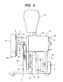
- Fig. 2 is a plan view showing an embodiment of the bywire system shift lever device for vehicles according to the present invention
- Fig. 3 is a cross sectional view showing a principal portion of the embodiment of the bywire system shift lever device for vehicle according to the present invention
- Fig. 4 is a block diagram illustrating a control system of the embodiment of the bywire system shift lever device for vehicles according to the present invention.
- a base member 1 being formed, for example, of metallic material or of synthetic resin material, and processed by cutting or molding, includes a substantially rectangle plate-shaped base plate portion 1a, a first supporting portion 1b extending outwardly and vertically with respect to one of the surfaces of the base plate portion 1a in parallel with the shorter side of the base plate portion 1a, a second supporting portion 1c disposed in parallel with the first supporting portion 1b at a predetermined distance away from the position of the first supporting portion 1b and being smaller than the first supporting portion 1b, a third supporting portion 1d disposed at a predetermined position between the first supporting portion 1b and the second supporting portion 1c in parallel with the first supporting portion 1b, and a mounting station 1e of a predetermined configuration disposed in the vicinity of the four corners of the other surface of the base plate portion 1a.
- the first supporting portion 1b is formed to have a predetermined thickness and includes a pair of side surfaces 1f disposed opposingly in parallel with each other, a sliding surface 1g in substantially semi-circular provided between the respective extremities of the pair of side surfaces 1f, a slit portion 1h provided in parallel with the shorter side of the base plate portion 1a and formed from one side surface If toward the other side surface 1f, a screw hole 1j formed so as to pass through the portion between the bottom surface of the slit portion 1h and the other side surface 1f, a circular mounting hole 1k provided at the substantially center of the first supporting portion 1b, and a mounting portion 1r such as a screw hole or a projection formed on the sliding surface 1g on the other side surface 1f.
- the substantially semi-circular sliding surface 1g of the first supporting portion 1b constitutes a large-diameter second pulley.
- the first supporting portion 1b being formed integrally with the base plate portion 1a, may be formed separately from the base plate portion 1a, so that the first supporting portion 1b is secured to the base plate portion 1a by suitable means such as screwing or the like.
- the second supporting portion 1c is formed to have a predetermined thickness and has a circular mounting hole 1m formed at the substantially center of the second supporting portion 1c.
- the central axis of the mounting hole 1m of the second supporting portion 1c and the central axis of a mounting hole 1k of the first supporting portion 1b are coaxial.
- the second supporting portion 1c being formed integrally with the base plate portion 1a, may be formed separately from the base plate portion 1a, so that the second supporting portion 1c is secured to the base plate portion 1a by means of suitable means such as, for example, screwing.
- the third supporting portion 1d is formed to have a predetermined thickness, and includes a substantially semi-circular hole In at the substantially center of the third supporting portion 1d and a pair of screw holes 1p disposed at predetermined positions so as to interpose the hole In.
- the third supporting portion 1d being formed integrally with the base plate portion 1a, may be formed separately from the base plate portion 1a so that the third supporting portion 1d is secured to the base plate portion 1a by means of suitable means such as screwing or the like.
- the first rotary mounting member 2 as a first mounting pin is formed, for example, of metallic material, processed by cutting into a column shape having a predetermined diameter and a length.
- Two first rotary mounting members 2 are provided, which are for example rotatably mounted to the mounting hole 1k of the first supporting portion 1b and the mounting hole 1m of the second supporting portion 1c respectively, and the respective extremities are disposed so as to project between the first supporting portion 1b and the second supporting portion 1c.
- the axial centers of these two first rotary mounting members 2 are disposed coaxially.
- the tensile screw member 3 includes a threaded portion 3a having a predetermined diameter, and a mounting portion 3b provided at the one of the ends of the threaded portion 3a.
- the tensile screw member 3 is mounted by being engaged within the screw hole 1j of the first supporting portion 1b of the base plate member 1, and in such an engaged state, the mounting portion 3b is projected into the slit portion 1h.
- the tensile screw member 3 is adapted to be capable of adjusting the amount of projection into the slit portion 1h of the mounting portion 3b.
- a tensile spring member 4 is, for example, a coiled spring, having a predetermined wire diameter and diameter, including a spring portion 4a having a predetermined tensility and a pair of mounting portions 4b provided at both ends of the spring portion 4a.
- the tensile spring member 4 is disposed on the side of the opening of the slit portion 1h of the first supporting portion 1b, and one of mounting portions 4b is, for example, hooked to the mounting portion 3b of the tensile screw member 3 so as not to come off easily.
- the other mounting portion 4b is disposed within the slit portion 1h.
- the tensile screw member 3 constitutes so-called a adjusting member for adjusting tensility of the tensile spring member 4 in such a manner that the mounting portion 3b of the tensile screw member 3 is moved back and forth in the slit portion 1h by rotating the tensile screw member 3.
- the first arm portion 5b is provided with a second securing hole 5j at the position further from the free end of the first arm portion 5b than the first securing hole 5e
- the second mounting portion 5g is provided with an insertion hole 5k formed at the substantially center of the second mounting portion 5g and a plurality of mounting holes 5m provided at predetermined positions so as to interpose the insertion hole 5k.
- the first mounting portion 5f is formed with a plurality of screw holes 5n on the outer end surface of the first mounting portion 5f.
- the first rotary mounting member 2 is firmly fixed to the respective securing holes 5e of the pair of the first and the second arm portions 5b and 5c of the lever member 5, for example, by press-fitting or by calking, and such fixation of the rotary mounting member 2 allows the lever member 5 to rotate in the directions indicated by an arrow A and an arrow B (See Fig. 1) about the securing hole 5e as a fulcrum.
- the lever member 5 is disposed between the first supporting portion 1b and the second supporting portion 1c, and mounted to the first supporting portion 1b and the second supporting portion 1c by the first rotary mounting member 2 so as to rotate within a predetermined angular region.
- An electric motor 6 as an actuator includes a cylindrical main body 6a in which an electromagnetic coil (not shown) and the like are stored, a drive shaft 6b as a rotating shaft provided so as to project outward from the main body 6a, a plurality of screw holes 6c formed around the drive shaft 6b, and a plurality of terminals 6d provided so as to project outward from the main body 6a.
- the electric motor 6 is secured to the second mounting portion 5g in such a manner that the drive shaft 6b is inserted through the insertion hole 5k of the second mounting portion 5g of the lever member 5 so as to project outward while aligning a mounting hole 5m on the second mounting portion 5g and the screw hole 6c, and secured with the screw 21.
- the electric motor 6 is mounted on the lever member 5.
- a pulley member 7 as a first pulley having a smaller diameter is formed, for example, of metallic material, processed by cutting, and includes a cylindrical winding portion 7a, a drive shaft 7b being coaxial with the winding portion 7a and having a diameter smaller than that of the winding portion 7a, and a circular recess (not shown) formed in the winding portion 7a coaxially with the winding portion 7a.
- the diameter of the pulley member 7 is adapted to be smaller than that of the sliding surface 1g of the first supporting portion 1b constituting the second pulley having a larger diameter, and the ratio of the diameter is, for example 1:13.
- the pulley member 7 is disposed in such a manner that the drive shaft 6b of the electric motor 6 is disposed within the recess (not shown) and the pulley member 7 is secured to the drive shaft 6b by suitable means such as screwing or the like.
- Awire 8 is formed, for example, of metallic wire material, and includes a linear portion 8a of a predetermined length and a pair of mounting portions 8b provided at both ends of the linear portion 8a.
- the wire 8 has a predetermined tensile strength, for example, 10kg, and is adapted to be broken (disconnected) when it is pulled with tensility in excess of this predetermined tensile strength.
- the wire 8 is secured in such a manner that one of the mounting portions 8b is secured to the mounting portion 1r of the first supporting portion 1b, for example, with a screw (not shown), and the other mounting portion 8b is engaged by the other mounting portion 4b of the tensile spring member 4, for example, in a hooked state.
- a linear portion 8a of the wire 8 is disposed in a state of being wound by a plurality of turns (for example, four turns), on the winding portion 7a of the pulley member 7, and the linear portion 8a other than the linear portion 8a wound around the winding portion 7a is disposed in a state of being in contact with the sliding surface 1g of the first supporting portion 1b.
- the wire 8 is disposed in such a manner that the linear portion 8a between a pair of mounting portions 8b disposed at both ends thereof is wound around the pulley member 7.
- the mounting substrate 9 is secured to a screw hole 5n of the first mounting portion 5f by disposing a mounting substrate 9 in contact with the outer surface of the first mounting portion 5e of the lever member 5, inserting a screw 22 through a plurality (two, for example) of the first mounting holes 9b, and fastening the screw 22.
- An absolute angle detecting sensor 10 as a first position detecting sensor is, for example, a potentiometer, and includes a substantially cylindrical body portion 10a in which a detecting portion (not shown) constructed, for example, of a resistive element or slide element for detecting the absolute angle, a pair of flanges 10b formed at the front end of the body portion 10a in a state of a rib, mounting holes 10c formed at substantially the centers of the respective flanges 10b, a detecting shaft 10d projecting outward from the front end of the body portion 10a, and a plurality of terminals (not shown) projecting outward from predetermined positions on the body portion 10a.
- a detecting portion constructed, for example, of a resistive element or slide element for detecting the absolute angle
- a pair of flanges 10b formed at the front end of the body portion 10a in a state of a rib
- mounting holes 10c formed at substantially the centers of the respective flanges 10b
- the absolute angle detecting sensor 10 is mounted to the third supporting member 1d by disposing the mounting holes10c so as to opposed to a pair of screw holes 1p of the third supporting portion 1d of the base member 1 in contact manner, and fastening a screw 23.
- a detecting shaft 10d projects outward from the inside of the hole In of the third supporting portion 1d, and is disposed in such a manner that the axial center of the detecting shaft 10d is coaxially disposed with the axial centers of the two aforementioned first rotary mounting members 2.
- a driving member 11 being formed, for example, of metallic plate material, processed by pressing into a substantially elliptic shape, includes circular first mounting holes 11a formed respectively in the vicinity of both ends thereof, and a circular second mounting hole 11b.
- the driving member 11 is disposed inside one of the first arm portions 5b of the lever member 5 in parallel with the first arm portion 5b, and the detecting shaft 10d of the absolute angle detecting sensor 10 is secured into the first mounting hole 11a by means of suitable means such as press-fitting.
- the second rotary mounting member 12 as a second mounting pin being formed, for example, of metallic material processed by cutting into a column shape, has a predetermined diameter and length.
- the second rotary mounting member 12 is secured in such a manner that one of the ends thereof is fixed to the second mounting hole 11b of the driving member 11 by suitable means such as press-fitting, and the other end is fixed to the second securing hole 5j of the first arm portion 5b in suitable means such as press-fitting.
- the driving member 11 rotates about the detecting shaft 10d of the absolute angle detecting sensor 10 together with the lever member 5. Rotation of the driving member 11 allows the detecting shaft 10d to rotate, and accordingly, the absolute angle is supplied from the absolute angle detecting sensor 10 as output signals toward the outside.
- An encoder 13 as the second position detecting sensor includes a main body 13a in which a code plate (not shown) and a slide element (not shown) are accommodated, a plurality of terminals 13b projecting outward from the main body 13a, an operating hole (not shown) provided at substantially the center of the main body 13a, and a plurality of screw holes (not shown) formed in the vicinity of the operating hole (not shown).
- the encoder 13 is attached to the mounting substrate 9 with a screw 24, which allows the driving shaft 7b of the pulley member 7 to be inserted into the operating hole (not shown), and the operating hole and the driving shaft 7b are secured by suitable means.
- An operating knob 14 as the operating element being formed, for example, of synthetic resin material, processed by molding into a substantially conical shape, includes a circular recess (not shown) along the axis of the operating knob 14.
- a third mounting portion 5i of the lever member 5 is inserted into the recess of the operating knob 14, and the third mounting portion 5i is fixed into the recess by suitable means.
- the electric motor is employed as an actuator.
- the actuator is not limited to the electric motor as far as it is rotary type electric equipment having a predetermined rotational torque.
- the potentiometer is employed as the first position detecting sensor.
- the first position detecting sensor is not limited to the potentiometer as far as it is the absolute angle detecting sensor that can detect the absolute angle.
- the encoder is employed as the second position detecting sensor.
- the second position detecting sensor is not limited to the encoder as far as it is the position detecting sensor that can detect predetermined position, speed, and rotational direction.
- FIG. 4 a block diagram of a control system for controlling the bywire system shift lever device for vehicles relating to the present bywire system shift lever device for vehicles will now be described.
- the control system of the bywire system shift lever device for vehicles includes: a shift lever device portion 50 including a base member 1 and a lever member 5 having the operating knob 14 disposed on the base member 1; an electric motor 6 mounted on the lever member 5; the absolute angular position detecting sensor 10 for supplying the first position signals in accordance with the operating angle of the lever member 5; a central processing unit 51 for controlling the electric motor 6 by the first position signals from the absolute angle detecting sensor 10 representing the shift position of the lever member 5; a transmission control unit 52 to which the output signals including the first position signals representing the shift position supplied from the central processing unit 51 are supplied; and an engine control unit 53 for supplying control signals such as the number of revolutions of the engine (not shown) to the central processing unit 51.
- the output signals representing the shift position of the lever member 5 that is controlled by the transmission from the transmission control unit 52 is supplied to the central processing unit 51.
- the central processing unit 51 is also supplied with the output signals from the encoder 13 (See Fig. 1) serving as the second position detecting sensor, and such signals supplied from the encoder 13 to the central processing unit 51 detects and controls the rotational direction of the electric motor 6.
- first position signals representing that the lever member 5 is at the drive (D) position emitted from the absolute angle detecting sensor 10 are supplied to the central processing unit 51, and by such first position signals, the central processing unit 51 outputs drive position locking signals for locking the electric motor 6 at the predetermined position, and also the first position signals representing that the lever member 5 is at the drive (D) position to the transmission control unit 52.
- sift status signals representing that the transmission from the transmission control unit 52 is controlled at the drive (D) position and signals representing the number of revolution of the engine (not shown) supplied from the engine control unit 53 are supplied to the central processing unit 51.
- the vehicle is adapted to be controlled stably at the drive (D) mode.
- the bywire system shift lever device for vehicles is intended to be used in automatic vehicles, and the shift positions of the lever member 5 may be set from the first position at the furthest position (the front of the vehicle) represented by the arrow A in Fig. 1 sequentially to the sixth position on the near side (the rear of the vehicle) represented by the arrow B.
- the first position is the parking (P) position
- the second position is the reverse (R) position
- the third position is the neutral (N) position
- the fourth position is the drive (D) position
- the fifth position is the second gear position
- the sixth position is the first gear position.
- the positions from the first position to the sixth position are equally spaced by a predetermined distance (the same angle), or set at predetermined intervals.
- the lever member 5 is adapted to be positioned at these first to sixth positions by applying a predetermined force.
- the description will be started from the state in which the operating knob (operating element) 14 provided at the lever member 5 is positioned at the N position, which is the third position.
- the absolute angle detecting sensor 10 outputs signals representing the absolute angle of the operating knob 14 disposed at the N position.
- the absolute angle detecting sensor 10 detects that the output signals indicating the absolute angle of the operating knob 14 located at the N position and that the operating knob 14 is going to be operated in the direction indicated by the arrow B.
- a voltage is applied to the drive shaft 6b of the electric motor 6 so as to rotate the same in the direction indicated by the arrow A (counterclockwise), which is opposite from the direction indicated by the arrow B.
- Detection and control of the rotation of the drive shaft 66 in the direction indicated by the arrow A is performed by output signals supplied by rotating the encoder 13 by the drive shaft 7b of the pulley member 7 secured to the drive shaft 6b.
- the encoder 13 as the second position detecting sensor, the rotational direction and the rotational speed of the pulley member 7 mounted to the electric motor 6 are detected and supplied so that the electric motor 6 can be controlled by such output signals.
- the pulley member 7 rotates counterclockwise at a predetermined torque (for example, a rotational torque of about 2 kg).
- a predetermined torque for example, a rotational torque of about 2 kg.
- the wire 8 wound around the pulley member 7 is applied with a counterclockwise rotational torque.
- the operating force to move the operating knob 14 in the direction indicated by the arrow B for example, about 3 kg
- the operating knob 14 is moved to the drive (D) position, which is the fourth position corresponding to the next position in the direction indicated by the arrow B.
- the winding position of the wire 8 moves over the sliding surface 1g of the first supporting portion 1b in the direction indicated by the arrow B while rotating the pulley member 7. Since the drive shaft 6b of the electric motor 6 is going to rotate counterclockwise in response to rotation of the pulley member 7 on the sliding surface 1g, such rotation of the drive shaft 6b may provide a predetermined sensory resistance to the operating knob 14.
- the output signals from the absolute angle detecting sensor 10 locks the operating knob 14 at the D position by a predetermined torque.
- the operation of the operating knob 14 to which a predetermined sensory resistance is applied is not limited to the operation of the operating knob 14 from the third position to the fourth position as described above, and is also applicable to the operation of the operating knob 14 between any adjacent positions from the first to the sixth position in the direction indicated by the arrow A or in the direction indicated by the arrow B as a matter of course.
- the pulley member 7 is constructed in such a manner that the winding position of the wire 8 wound around the pulley member 7 always moves over the sliding surface 1g while rotating the pulley member 7 by operating the lever member 6 when the operating knob 14 is operated between any positions described above.
- the sliding movement of the wire 8 over the outer surface of the pulley member 7 allows the operating knob 14 to be moved in the direction indicated by the arrow B, so that the operating knob 14 may be moved to the D position corresponding to the intended fourth position.
- the operation of the operating knob 14 as described above is not limited to the operation of the operating knob 14 from the third position to the fourth position as described above, and the wire 8 also moves as if it slides over the outer surface of the pulley member 7 between any adjacent positions from the first to the sixth position in the direction indicated by the arrow A or in the direction indicated by the arrow B as a matter of course.
- the operation that the wire 8 moves as if it slides over the outer surface of the pulley member 7 when there is a problem has been described in the above described embodiment, it is also possible to construct the device in such a manner that the wire 8 is broken by applying an operating force, for example, of more than about 10 kg to the operating knob 14 to enable the operation of the operating knob 14, as a matter of course.
- the bywire system shift lever device for vehicles includes : a base member; a lever member mounted on the base member so as to be capable of being driven within a predetermined range of angles and having an operating element; the lever member being driven by operating the operating element; an electric motor mounted on the lever member; a transmission mechanism for transmitting rotation of the rotating shaft of the electric motor to the lever member; the first position detecting sensor for supplying first position signals representing the operating angle of the lever member; and the second position detecting sensor for supplying second position signals representing the operation of the lever member via the transmission mechanism, and a rotational force of the rotating shaft of the electric motor is controlled by the second position signals, so that a predetermined sensory resistance is provided to the operating element by a force of the rotating shaft of the electric motor applied via the transmission mechanism. Consequently, the sensory resistance providing mechanism is constructed of the electric motor and the transmission mechanism for transmitting the rotation of the rotating shaft of the electric motor to the lever member, and thus the structure is simplified and the compact shift lever device for vehicles may be provided.
- the transmission mechanism includes: a wire the both ends of which are attached to the base member; and a pulley secured to the rotating shaft of the electric motor, and the wire is wound around the pulley between both ends thereof, the winding position of the wire wound around the pulley is moved while rotating the pulley by the operation of the lever member, and the rotating shaft of the electric motor is rotated in the direction opposite from the direction of rotation of the pulley, so that a predetermined sensory resistance is provided to the operating element.
- the construction of the transmission mechanism is such simple that the wire is simply wound around the pulley, and thus the pulley can be moved as if the wire slides over the outer peripheral surface of the pulley in some cases. Therefore, even when the rotating shaft of the electric motor cannot be rotated due to a defect thereof, the first position signals representing the operating angle of the lever member may be supplied from the first position detecting sensor by moving the lever member and thus the reliable operation of the lever member is achieved.
Abstract
Description
- The present invention relates to a bywire system shift lever device for vehicles, and, more specifically, to a bywire system shift lever device suitable for automatic vehicles.
- Hitherto, the shift lever device for automatic vehicles is provided with a transmission switching unit utilizing a mechanical link mechanism. However, in order to cope with demand for computerization of vehicle-mounted equipment, a bywire system transmission switching unit in which the switching position of the shift lever is detected by a position sensor, and an actuator such as a solenoid and a motor is driven in accordance with output signals from the position sensor to drive a transmission switching fork is proposed.
- With the shift lever device for automatic vehicles having the bywire system transmission switching unit, it is not necessary to provide a large sized and complex link mechanism between the driver's seat and the engine room, and what have to be done is just to distribute several pieces of electric wires, whereby flexibility of design of the vehicle may be significantly increased.
- The shift lever device for automatic vehicles requires a sensory resistance providing mechanism for providing an adequate sensory resistance to the shift lever when the shift lever is moved from one shift position (for example, the drive position: D) to another shift position (for example, the neutral position: N) in order to ensure good operability of the shift lever.
- The bywire system shift lever device for vehicles, which has been proposed in the related art, is also provided with the sensory resistance providing mechanism. However, there is such disadvantage that when the sensory resistance providing mechanism in the related art has a problem, such sensory resistance providing mechanism tends to be locked at the position having the problem, whereby change of the shift position by the shift lever is disabled.
- In addition, there is another problem that complex construction of the sensory resistance providing mechanism results in upsizing of the sensory resistance providing mechanism.
- In order to solve the problem described above, an object of the bywire system shift lever device for vehicles according to the present invention is to provide a compact bywire system shift lever device for vehicles, in which reliable change gear operation is achieved.
- The bywire system shift lever device for vehicles according to the present invention includes: a base member; a lever member mounted on the base member so as to be capable of being driven within a predetermined range of angles and having an operating element; the lever member being driven by operating the operating element; an electric motor mounted on the lever member; a transmission mechanism for transmitting rotation of a rotating shaft of the electric motor to the lever member; a first position detecting sensor for supplying first position signals representing the operating angle of the lever member; and a second position detecting sensor for supplying second position signals representing the operation of the lever member via the transmission mechanism, and a rotational force of the rotating shaft of the electric motor is controlled by the second position signals so that a predetermined sensory resistance is provided to the operating element by a force of the rotating shaft of the electric motor applied via the transmission mechanism.
- In this arrangement, since the sensory resistance providing mechanism is constructed of the electric motor and the transmission mechanism for transmitting the rotation of the rotating shaft of the electric motor to the lever member, the structure is simplified, and thus the compact shift lever device for vehicles may be provided.
- In the bywire system shift lever device for vehicles according to the present invention, the transmission mechanism includes: a wire the both ends of which are attached to the base member; and a pulley secured to the rotating shaft of the electric motor, and the wire is wound around the pulley between both ends thereof, the winding position of the wire wound around the pulley is moved while rotating the pulley by the operation of the lever member, and the rotating shaft of the electric motor is rotated in the direction opposite from the direction of rotation of the pulley, so that a predetermined sensory resistance is provided to the operating element.
- In this arrangement, since the construction of the transmission mechanism is such that the wire is simply wound around the pulley, the pulley can be moved as if the wire slides over the outer peripheral surface of the pulley in some cases. Therefore, even when the rotating shaft of the electric motor cannot be rotated due to a defect thereof, the first position signals representing the operating angle of the lever member may be supplied from the first position detecting sensor by moving the lever member and thus the reliable operation of the lever member is achieved.
- The bywire system shift lever device for vehicles according to the invention is characterized in that a supporting unit having a semi-circular sliding surface, the diameter of which is larger than the diameter of the pulley, is provided on the base member, in that the outer peripheral surface of the pulley and the sliding surface of the supporting unit are faced toward each other, and in that the wire is positioned along the sliding surface of the supporting unit so that the winding position of the wire on the pulley moves along the sliding surface.
- In this arrangement, since a speed reducing mechanism is constructed by the pulley, which is smaller in diameter, and the sliding surface, which is larger in diameter, a small electric motor having small rotational torque may be arranged and thus a compact bywire system shift lever device for vehicles being blessed with stable operation may be provided at a low cost.
- The bywire system shift lever device according to the present invention is characterized in that a spring member is attached at one of the ends of the wire, and the spring member is provided with an adjusting member for adjusting the tensility thereof.
- In this arrangement, the tensility of the wire may be adjusted to a predetermined force easily by the adjusting member attached to the spring member, and thus a predetermined stable sensory resistance may be achieved.
- The bywire system shift lever device for vehicles according to the invention is characterized in that the electric motor is disposed on the side of the operating element of the lever member, and the first position detecting sensor is disposed within the moving range of the lever member on the base member on the fulcrum side of the lever member.
- In this arrangement, the device may be downsized, and the position of the lever member within the predetermined angular range may be reliably detected by the first position detecting sensor.
- The bywire system shift lever device for vehicles according to the present invention is characterized in that the first position detecting sensor is constructed of a potentiometer, and the second position detecting sensor is constructed of an encoder.
- Since the potentiometer and the encoder are low in price, the cost-effective bywire system shift lever device for vehicles may be provided.
- The bywire system shift lever device for vehicles according to the present invention is characterized in that the wire wound around the pulley moves as if it slides over the outer peripheral surface of the pulley by operating the operating element when the transmission mechanism fails to be driven or when the electric motor fails to be rotated, so that the lever member can actuate the first position detecting sensor, and thus the electric motor can be controlled by the first position signals from the first position detecting sensor.
- In this arrangement, the bywire system shift lever device for vehicles in which the position of the shift lever can be reliably detected within a predetermined angular range by the first position detecting sensor even when the transmission mechanism or the electric motor has a problem, which may occur on occasion.
-
- Fig. 1 is an exploded perspective view showing an embodiment of the bywire system shift lever device for vehicles according to the present invention;
- Fig. 2 is a plan view showing an embodiment of the bywire system shift lever device for vehicles according to the present invention;
- Fig. 3 is a cross sectional view showing a principal portion of the embodiment of the bywire system shift lever device for vehicles according to the present invention; and
- Fig. 4 is a block diagram illustrating a control system of the embodiment of the bywire system shift lever device for vehicles according to the present invention.
- Referring to the drawings of the bywire system shift lever device for vehicles according to the invention, Fig. 1 is an exploded perspective view showing an embodiment of the bywire system shift lever device for vehicles according to the present invention; Fig. 2 is a plan view showing an embodiment of the bywire system shift lever device for vehicles according to the present invention; Fig. 3 is a cross sectional view showing a principal portion of the embodiment of the bywire system shift lever device for vehicle according to the present invention; and Fig. 4 is a block diagram illustrating a control system of the embodiment of the bywire system shift lever device for vehicles according to the present invention.
- A
base member 1 being formed, for example, of metallic material or of synthetic resin material, and processed by cutting or molding, includes a substantially rectangle plate-shapedbase plate portion 1a, a first supportingportion 1b extending outwardly and vertically with respect to one of the surfaces of thebase plate portion 1a in parallel with the shorter side of thebase plate portion 1a, a second supportingportion 1c disposed in parallel with the first supportingportion 1b at a predetermined distance away from the position of the first supportingportion 1b and being smaller than the first supportingportion 1b, a third supportingportion 1d disposed at a predetermined position between the first supportingportion 1b and the second supportingportion 1c in parallel with the first supportingportion 1b, and amounting station 1e of a predetermined configuration disposed in the vicinity of the four corners of the other surface of thebase plate portion 1a. - The first supporting
portion 1b is formed to have a predetermined thickness and includes a pair ofside surfaces 1f disposed opposingly in parallel with each other, a slidingsurface 1g in substantially semi-circular provided between the respective extremities of the pair ofside surfaces 1f, aslit portion 1h provided in parallel with the shorter side of thebase plate portion 1a and formed from one side surface If toward theother side surface 1f, ascrew hole 1j formed so as to pass through the portion between the bottom surface of theslit portion 1h and theother side surface 1f, acircular mounting hole 1k provided at the substantially center of the first supportingportion 1b, and amounting portion 1r such as a screw hole or a projection formed on the slidingsurface 1g on theother side surface 1f. - The substantially semi-circular sliding
surface 1g of the first supportingportion 1b constitutes a large-diameter second pulley. - The first supporting
portion 1b being formed integrally with thebase plate portion 1a, may be formed separately from thebase plate portion 1a, so that the first supportingportion 1b is secured to thebase plate portion 1a by suitable means such as screwing or the like. - The second supporting
portion 1c is formed to have a predetermined thickness and has acircular mounting hole 1m formed at the substantially center of the second supportingportion 1c. The central axis of themounting hole 1m of the second supportingportion 1c and the central axis of amounting hole 1k of the first supportingportion 1b are coaxial. - The second supporting
portion 1c, being formed integrally with thebase plate portion 1a, may be formed separately from thebase plate portion 1a, so that the second supportingportion 1c is secured to thebase plate portion 1a by means of suitable means such as, for example, screwing. - The third supporting
portion 1d is formed to have a predetermined thickness, and includes a substantially semi-circular hole In at the substantially center of the third supportingportion 1d and a pair ofscrew holes 1p disposed at predetermined positions so as to interpose the hole In. - The third supporting
portion 1d, being formed integrally with thebase plate portion 1a, may be formed separately from thebase plate portion 1a so that the third supportingportion 1d is secured to thebase plate portion 1a by means of suitable means such as screwing or the like. - The first
rotary mounting member 2 as a first mounting pin is formed, for example, of metallic material, processed by cutting into a column shape having a predetermined diameter and a length. Two firstrotary mounting members 2 are provided, which are for example rotatably mounted to themounting hole 1k of the first supportingportion 1b and themounting hole 1m of the second supportingportion 1c respectively, and the respective extremities are disposed so as to project between the first supportingportion 1b and the second supportingportion 1c. - The axial centers of these two first
rotary mounting members 2 are disposed coaxially. - The
tensile screw member 3 includes a threadedportion 3a having a predetermined diameter, and amounting portion 3b provided at the one of the ends of the threadedportion 3a. Thetensile screw member 3 is mounted by being engaged within thescrew hole 1j of the first supportingportion 1b of thebase plate member 1, and in such an engaged state, themounting portion 3b is projected into theslit portion 1h. - The
tensile screw member 3 is adapted to be capable of adjusting the amount of projection into theslit portion 1h of themounting portion 3b. - A
tensile spring member 4 is, for example, a coiled spring, having a predetermined wire diameter and diameter, including a spring portion 4a having a predetermined tensility and a pair of mountingportions 4b provided at both ends of the spring portion 4a. - The
tensile spring member 4 is disposed on the side of the opening of theslit portion 1h of the first supportingportion 1b, and one of mountingportions 4b is, for example, hooked to themounting portion 3b of thetensile screw member 3 so as not to come off easily. - In this state, the
other mounting portion 4b is disposed within theslit portion 1h. - In this state, the
tensile screw member 3 constitutes so-called a adjusting member for adjusting tensility of thetensile spring member 4 in such a manner that themounting portion 3b of thetensile screw member 3 is moved back and forth in theslit portion 1h by rotating thetensile screw member 3. - A
lever member 5, being formed, for example, of metallic material, synthetic resin material, or the like, processed by cutting or molding, includes: a plate shapedbase portion 5a; a pair of first andsecond arm portions base portion 5a; a supportingportion 5d for connecting the pair of first andsecond arm portions second arm portions holes 5e formed at the coaxial positions in the vicinity of the respective free ends of the pair of first andsecond arm portions portion 5f projecting outward from the outer surface of thefirst arm portion 5b on the root side thereof; substantially semi-circularsecond mounting portion 5g projecting from the root side of thefirst arm portion 5b outwardly so as to be flush with the outer surface of thefirst arm portion 5b; anarcuate recess 5h provided at a predetermined position of the longitudinal side of thesecond arm portion 5c; and a column-shapedthird mounting portion 5i projecting vertically outward from the substantially central portion of the surface of thebase portion 5a. - The
first arm portion 5b is provided with a second securing hole 5j at the position further from the free end of thefirst arm portion 5b than the first securinghole 5e, and thesecond mounting portion 5g is provided with aninsertion hole 5k formed at the substantially center of thesecond mounting portion 5g and a plurality ofmounting holes 5m provided at predetermined positions so as to interpose theinsertion hole 5k. - The
first mounting portion 5f is formed with a plurality ofscrew holes 5n on the outer end surface of thefirst mounting portion 5f. - The first
rotary mounting member 2 is firmly fixed to the respective securingholes 5e of the pair of the first and thesecond arm portions lever member 5, for example, by press-fitting or by calking, and such fixation of therotary mounting member 2 allows thelever member 5 to rotate in the directions indicated by an arrow A and an arrow B (See Fig. 1) about the securinghole 5e as a fulcrum. In other words, thelever member 5 is disposed between the first supportingportion 1b and the second supportingportion 1c, and mounted to the first supportingportion 1b and the second supportingportion 1c by the firstrotary mounting member 2 so as to rotate within a predetermined angular region. - An
electric motor 6 as an actuator includes a cylindricalmain body 6a in which an electromagnetic coil (not shown) and the like are stored, adrive shaft 6b as a rotating shaft provided so as to project outward from themain body 6a, a plurality ofscrew holes 6c formed around thedrive shaft 6b, and a plurality ofterminals 6d provided so as to project outward from themain body 6a. - The
electric motor 6 is secured to thesecond mounting portion 5g in such a manner that thedrive shaft 6b is inserted through theinsertion hole 5k of thesecond mounting portion 5g of thelever member 5 so as to project outward while aligning amounting hole 5m on thesecond mounting portion 5g and thescrew hole 6c, and secured with thescrew 21. In other words, theelectric motor 6 is mounted on thelever member 5. - A
pulley member 7 as a first pulley having a smaller diameter is formed, for example, of metallic material, processed by cutting, and includes acylindrical winding portion 7a, adrive shaft 7b being coaxial with thewinding portion 7a and having a diameter smaller than that of thewinding portion 7a, and a circular recess (not shown) formed in thewinding portion 7a coaxially with thewinding portion 7a. - The diameter of the
pulley member 7 is adapted to be smaller than that of the slidingsurface 1g of the first supportingportion 1b constituting the second pulley having a larger diameter, and the ratio of the diameter is, for example 1:13. - The
pulley member 7 is disposed in such a manner that thedrive shaft 6b of theelectric motor 6 is disposed within the recess (not shown) and thepulley member 7 is secured to thedrive shaft 6b by suitable means such as screwing or the like. -
Awire 8 is formed, for example, of metallic wire material, and includes alinear portion 8a of a predetermined length and a pair of mountingportions 8b provided at both ends of thelinear portion 8a. - The
wire 8 has a predetermined tensile strength, for example, 10kg, and is adapted to be broken (disconnected) when it is pulled with tensility in excess of this predetermined tensile strength. - The
wire 8 is secured in such a manner that one of the mountingportions 8b is secured to the mountingportion 1r of the first supportingportion 1b, for example, with a screw (not shown), and the other mountingportion 8b is engaged by the other mountingportion 4b of thetensile spring member 4, for example, in a hooked state. Alinear portion 8a of thewire 8 is disposed in a state of being wound by a plurality of turns (for example, four turns), on the windingportion 7a of thepulley member 7, and thelinear portion 8a other than thelinear portion 8a wound around the windingportion 7a is disposed in a state of being in contact with the slidingsurface 1g of the first supportingportion 1b. In other words, thewire 8 is disposed in such a manner that thelinear portion 8a between a pair of mountingportions 8b disposed at both ends thereof is wound around thepulley member 7. - A mounting
substrate 9, being formed, for example, of metallic material or synthetic resin material, processed by pressing or molding, is shaped like a plate, and includes a throughhole 9a formed at a predetermined position, a plurality (two, for example) of first mountingholes 9b formed at predetermined positions, and a plurality (two, for example) of second mounting holes 9c. - The mounting
substrate 9 is secured to ascrew hole 5n of the first mountingportion 5f by disposing a mountingsubstrate 9 in contact with the outer surface of the first mountingportion 5e of thelever member 5, inserting ascrew 22 through a plurality (two, for example) of the first mountingholes 9b, and fastening thescrew 22. - In this state, the
drive shaft 7b of thepulley member 7 into the throughhole 9a, and the extremity of thedrive shaft 7b projects outward from the surface of the mountingsubstrate 9. - An absolute
angle detecting sensor 10 as a first position detecting sensor is, for example, a potentiometer, and includes a substantiallycylindrical body portion 10a in which a detecting portion (not shown) constructed, for example, of a resistive element or slide element for detecting the absolute angle, a pair offlanges 10b formed at the front end of thebody portion 10a in a state of a rib, mountingholes 10c formed at substantially the centers of therespective flanges 10b, a detectingshaft 10d projecting outward from the front end of thebody portion 10a, and a plurality of terminals (not shown) projecting outward from predetermined positions on thebody portion 10a. - The absolute
angle detecting sensor 10 is mounted to the third supportingmember 1d by disposing the mounting holes10c so as to opposed to a pair ofscrew holes 1p of the third supportingportion 1d of thebase member 1 in contact manner, and fastening ascrew 23. - In this case, a detecting
shaft 10d projects outward from the inside of the hole In of the third supportingportion 1d, and is disposed in such a manner that the axial center of the detectingshaft 10d is coaxially disposed with the axial centers of the two aforementioned firstrotary mounting members 2. - A driving
member 11, being formed, for example, of metallic plate material, processed by pressing into a substantially elliptic shape, includes circular first mountingholes 11a formed respectively in the vicinity of both ends thereof, and a circular second mountinghole 11b. - The driving
member 11 is disposed inside one of thefirst arm portions 5b of thelever member 5 in parallel with thefirst arm portion 5b, and the detectingshaft 10d of the absoluteangle detecting sensor 10 is secured into the first mountinghole 11a by means of suitable means such as press-fitting. - The second
rotary mounting member 12 as a second mounting pin, being formed, for example, of metallic material processed by cutting into a column shape, has a predetermined diameter and length. The secondrotary mounting member 12 is secured in such a manner that one of the ends thereof is fixed to thesecond mounting hole 11b of the drivingmember 11 by suitable means such as press-fitting, and the other end is fixed to the second securing hole 5j of thefirst arm portion 5b in suitable means such as press-fitting. - When the
lever member 5 is rotated within a predetermined angular range in this state, the drivingmember 11 rotates about the detectingshaft 10d of the absoluteangle detecting sensor 10 together with thelever member 5. Rotation of the drivingmember 11 allows the detectingshaft 10d to rotate, and accordingly, the absolute angle is supplied from the absoluteangle detecting sensor 10 as output signals toward the outside. - An
encoder 13 as the second position detecting sensor includes amain body 13a in which a code plate (not shown) and a slide element (not shown) are accommodated, a plurality ofterminals 13b projecting outward from themain body 13a, an operating hole (not shown) provided at substantially the center of themain body 13a, and a plurality of screw holes (not shown) formed in the vicinity of the operating hole (not shown). - The
encoder 13 is attached to the mountingsubstrate 9 with ascrew 24, which allows the drivingshaft 7b of thepulley member 7 to be inserted into the operating hole (not shown), and the operating hole and the drivingshaft 7b are secured by suitable means. - An operating
knob 14 as the operating element, being formed, for example, of synthetic resin material, processed by molding into a substantially conical shape, includes a circular recess (not shown) along the axis of the operatingknob 14. - A
third mounting portion 5i of thelever member 5 is inserted into the recess of the operatingknob 14, and thethird mounting portion 5i is fixed into the recess by suitable means. By operating the operatingknob 14 in the direction indicated by the arrows A and B, thelever member 5 is operated and driven about the firstrotary mounting member 2 as a fulcrum. - In the bywire system shift lever device for vehicles according to the present invention, the electric motor is employed as an actuator. However, the actuator is not limited to the electric motor as far as it is rotary type electric equipment having a predetermined rotational torque.
- In the bywire system shift lever device for vehicles according to the present invention, the potentiometer is employed as the first position detecting sensor. However, the first position detecting sensor is not limited to the potentiometer as far as it is the absolute angle detecting sensor that can detect the absolute angle.
- In the bywire system shift lever device for vehicles according to the present invention, the encoder is employed as the second position detecting sensor. However, the second position detecting sensor is not limited to the encoder as far as it is the position detecting sensor that can detect predetermined position, speed, and rotational direction.
- Referring now to Fig. 4, a block diagram of a control system for controlling the bywire system shift lever device for vehicles relating to the present bywire system shift lever device for vehicles will now be described.
- As shown in Fig. 4, the control system of the bywire system shift lever device for vehicles includes: a shift
lever device portion 50 including abase member 1 and alever member 5 having the operatingknob 14 disposed on thebase member 1; anelectric motor 6 mounted on thelever member 5; the absolute angularposition detecting sensor 10 for supplying the first position signals in accordance with the operating angle of thelever member 5; acentral processing unit 51 for controlling theelectric motor 6 by the first position signals from the absoluteangle detecting sensor 10 representing the shift position of thelever member 5; atransmission control unit 52 to which the output signals including the first position signals representing the shift position supplied from thecentral processing unit 51 are supplied; and anengine control unit 53 for supplying control signals such as the number of revolutions of the engine (not shown) to thecentral processing unit 51. - The output signals representing the shift position of the
lever member 5 that is controlled by the transmission from thetransmission control unit 52 is supplied to thecentral processing unit 51. - The
central processing unit 51 is also supplied with the output signals from the encoder 13 (See Fig. 1) serving as the second position detecting sensor, and such signals supplied from theencoder 13 to thecentral processing unit 51 detects and controls the rotational direction of theelectric motor 6. - Flow of signals in the above-described control system will be schematically described. For example, when the
lever member 5 is operated and positioned to the drive (D) position, first position signals representing that thelever member 5 is at the drive (D) position emitted from the absoluteangle detecting sensor 10 are supplied to thecentral processing unit 51, and by such first position signals, thecentral processing unit 51 outputs drive position locking signals for locking theelectric motor 6 at the predetermined position, and also the first position signals representing that thelever member 5 is at the drive (D) position to thetransmission control unit 52. - In this case, sift status signals representing that the transmission from the
transmission control unit 52 is controlled at the drive (D) position and signals representing the number of revolution of the engine (not shown) supplied from theengine control unit 53 are supplied to thecentral processing unit 51. - Accordingly, the vehicle is adapted to be controlled stably at the drive (D) mode.
- Almost the same control is performed even when the
lever member 5 is, for example, at a parking (P) position, a reverse (R) position, or a second gear position, and thus the description will not be made. - The operation of the bywire system shift lever device for vehicles will now be described. The bywire system shift lever device for vehicles is intended to be used in automatic vehicles, and the shift positions of the
lever member 5 may be set from the first position at the furthest position (the front of the vehicle) represented by the arrow A in Fig. 1 sequentially to the sixth position on the near side (the rear of the vehicle) represented by the arrow B. - In this case, the first position is the parking (P) position, the second position is the reverse (R) position, the third position is the neutral (N) position, the fourth position is the drive (D) position, the fifth position is the second gear position, and the sixth position is the first gear position. The positions from the first position to the sixth position are equally spaced by a predetermined distance (the same angle), or set at predetermined intervals.
- The
lever member 5 is adapted to be positioned at these first to sixth positions by applying a predetermined force. - The normal operation in such condition will now be described.
- The description will be started from the state in which the operating knob (operating element) 14 provided at the
lever member 5 is positioned at the N position, which is the third position. When the operatingknob 14 is disposed at the N position, the absoluteangle detecting sensor 10 outputs signals representing the absolute angle of the operatingknob 14 disposed at the N position. - When the operating
knob 14 disposed at the N position is operated in the direction indicated by the arrow B (clockwise), the absoluteangle detecting sensor 10 detects that the output signals indicating the absolute angle of the operatingknob 14 located at the N position and that the operatingknob 14 is going to be operated in the direction indicated by the arrow B. When such detection signals are detected, a voltage is applied to thedrive shaft 6b of theelectric motor 6 so as to rotate the same in the direction indicated by the arrow A (counterclockwise), which is opposite from the direction indicated by the arrow B. - Detection and control of the rotation of the drive shaft 66 in the direction indicated by the arrow A is performed by output signals supplied by rotating the
encoder 13 by thedrive shaft 7b of thepulley member 7 secured to thedrive shaft 6b. In other words, by employing theencoder 13 as the second position detecting sensor, the rotational direction and the rotational speed of thepulley member 7 mounted to theelectric motor 6 are detected and supplied so that theelectric motor 6 can be controlled by such output signals. - When a voltage that rotates the
drive shaft 6b of theelectric motor 6 as predetermined manner is applied, thepulley member 7 rotates counterclockwise at a predetermined torque (for example, a rotational torque of about 2 kg). In this case, thewire 8 wound around thepulley member 7 is applied with a counterclockwise rotational torque. However, if the operating force to move the operatingknob 14 in the direction indicated by the arrow B (for example, about 3 kg) is larger than the rotational torque, the operatingknob 14 is moved to the drive (D) position, which is the fourth position corresponding to the next position in the direction indicated by the arrow B. - At this moment, the winding position of the
wire 8 moves over the slidingsurface 1g of the first supportingportion 1b in the direction indicated by the arrow B while rotating thepulley member 7. Since thedrive shaft 6b of theelectric motor 6 is going to rotate counterclockwise in response to rotation of thepulley member 7 on the slidingsurface 1g, such rotation of thedrive shaft 6b may provide a predetermined sensory resistance to the operatingknob 14. - When the absolute
angel detecting sensor 10 detected that the operatingknob 14 has moved to the drive (D) position, the output signals from the absoluteangle detecting sensor 10 locks the operatingknob 14 at the D position by a predetermined torque. - As described above, the operation of the operating
knob 14 to which a predetermined sensory resistance is applied is not limited to the operation of the operatingknob 14 from the third position to the fourth position as described above, and is also applicable to the operation of the operatingknob 14 between any adjacent positions from the first to the sixth position in the direction indicated by the arrow A or in the direction indicated by the arrow B as a matter of course. Thepulley member 7 is constructed in such a manner that the winding position of thewire 8 wound around thepulley member 7 always moves over the slidingsurface 1g while rotating thepulley member 7 by operating thelever member 6 when the operatingknob 14 is operated between any positions described above. - Subsequently, the operation to be performed when the transmission mechanism or the electric motor of the bywire system shift lever device for vehicles has a problem, such as catching of a foreign substance into the transmission mechanism or burning phenomenon of sliding element of the motor, which may occur on occasions, will be described. In other words, the operation performed when the
pulley member 7 cannot be rotated as usual will be described. - The operation in such a case will also be described from the state in which the operating knob (operating element) 14 provided on the
lever member 5 is located at the N position, which corresponds to the third position. - As in the case described above, when the operator tries to operate the operating
knob 14 located at the N position in the direction indicated by the arrow B (clockwise) from this state, as described above, the normal (correct) action of the transmission mechanism or the electric motor may not be performed due to such a problem that may occur on occasions. - In this state, when the operator tries to operate the operating
knob 14 in the direction indicated by the arrow B (clockwise) with an operating force (5 kg, for example) in excess of a predetermined operating force (about 2 kg, for example), thepulley member 7 secured to thedrive shaft 6b of theelectric motor 6 does not rotate by itself (pulley member 7) due to the problem, and thewire 8 wound around thepulley member 7 moves as if it slides over the outer surface of thepulley member 7. - The sliding movement of the
wire 8 over the outer surface of thepulley member 7 allows the operatingknob 14 to be moved in the direction indicated by the arrow B, so that the operatingknob 14 may be moved to the D position corresponding to the intended fourth position. - The operation of the operating
knob 14 as described above is not limited to the operation of the operatingknob 14 from the third position to the fourth position as described above, and thewire 8 also moves as if it slides over the outer surface of thepulley member 7 between any adjacent positions from the first to the sixth position in the direction indicated by the arrow A or in the direction indicated by the arrow B as a matter of course. - Although the operation that the
wire 8 moves as if it slides over the outer surface of thepulley member 7 when there is a problem has been described in the above described embodiment, it is also possible to construct the device in such a manner that thewire 8 is broken by applying an operating force, for example, of more than about 10 kg to the operatingknob 14 to enable the operation of the operatingknob 14, as a matter of course. - As described above, since the bywire system shift lever device for vehicles according to the invention includes : a base member; a lever member mounted on the base member so as to be capable of being driven within a predetermined range of angles and having an operating element; the lever member being driven by operating the operating element; an electric motor mounted on the lever member; a transmission mechanism for transmitting rotation of the rotating shaft of the electric motor to the lever member; the first position detecting sensor for supplying first position signals representing the operating angle of the lever member; and the second position detecting sensor for supplying second position signals representing the operation of the lever member via the transmission mechanism, and a rotational force of the rotating shaft of the electric motor is controlled by the second position signals, so that a predetermined sensory resistance is provided to the operating element by a force of the rotating shaft of the electric motor applied via the transmission mechanism. Consequently, the sensory resistance providing mechanism is constructed of the electric motor and the transmission mechanism for transmitting the rotation of the rotating shaft of the electric motor to the lever member, and thus the structure is simplified and the compact shift lever device for vehicles may be provided.
- In addition, in the bywire system shift lever device for vehicles according to the present invention, the transmission mechanism includes: a wire the both ends of which are attached to the base member; and a pulley secured to the rotating shaft of the electric motor, and the wire is wound around the pulley between both ends thereof, the winding position of the wire wound around the pulley is moved while rotating the pulley by the operation of the lever member, and the rotating shaft of the electric motor is rotated in the direction opposite from the direction of rotation of the pulley, so that a predetermined sensory resistance is provided to the operating element. Consequently, the construction of the transmission mechanism is such simple that the wire is simply wound around the pulley, and thus the pulley can be moved as if the wire slides over the outer peripheral surface of the pulley in some cases. Therefore, even when the rotating shaft of the electric motor cannot be rotated due to a defect thereof, the first position signals representing the operating angle of the lever member may be supplied from the first position detecting sensor by moving the lever member and thus the reliable operation of the lever member is achieved.
Claims (7)
- A bywire system shift lever device for vehicles comprising:a base member;a lever member mounted on the base member so as to be capable of being driven within a predetermined range of angles and having an operating element;the lever member being driven by operating the operating element;an electric motor mounted on the lever member;a transmission mechanism for transmitting rotation of a rotating shaft of the electric motor to said lever member;a first position detecting sensor for supplying first position signals representing an operating angle of said lever member; anda second position detecting sensor for supplying second position signals representing the operation of said lever member via said transmission mechanism,wherein a rotational force of the rotating shaft of said electric motor is controlled by said second position signals so that a predetermined sensory resistance is provided to said operating element by a force of the rotating shaft of said electric motor applied via the transmission mechanism by controlling said electric motor.
- A bywire system shift lever device for vehicles according to Claim 1, wherein said transmission mechanism comprises a wire attached to said base member at both ends, and a pulley secured to the rotating shaft of said electric motor,
wherein the wire is wound on said pulley between the ends thereof so that the operation of said lever member allows the winding position of said wire wound on said pulley to move over said pulley while rotating, and
wherein the rotating shaft of said electric motor is controlled in the opposite direction from the direction of rotation of said pulley so that the predetermined sensory resistance is provided to said operating element. - A bywire system shift lever device for vehicles according to Claim 2, wherein said base member is provided with a supporting portion having a semi-circular sliding surface, which is larger in diameter than said pulley,
wherein the outer peripheral surface of said pulley is faced toward said sliding surface of said supporting portion, and
wherein said wire is disposed along said sliding surface of said supporting portion so that the winding position of said wire on said pulley moves along said sliding surface. - A bywire system shift lever device for vehicles according to Claim 2 or Claim 3, wherein a spring member is attached on one of the ends of said wire, and the spring member comprises an adjusting member for adjusting the tensility thereof.
- A bywire system shift lever device for vehicles according to any of Claims 1 to 4, wherein said electric motor is disposed on the side of said operating element of said lever member, and said first position detecting sensor is disposed within the moving range of said lever member on said base member on the fulcrum side of said lever member.
- A bywire system shift lever device for vehicles according to any of Claims 1 to 5, wherein said first position detecting sensor is constructed of a potentiometer, and said second position detecting sensor is constructed of an encoder.
- A bywire system shift lever device for vehicles according to any of Claims 2 to 6, wherein said wire wound around said pulley moves as if it slides over the outer peripheral surface of said pulley by operating said operating element when said transmission mechanism fails to be driven or when said electric motor fails to be rotated, so that said lever member can actuate said first position detecting sensor, and thus said electric motor can be controlled by the first position signals from said first position detecting sensor.
Applications Claiming Priority (2)
| Application Number | Priority Date | Filing Date | Title |
|---|---|---|---|
| JP2002059788 | 2002-03-06 | ||
| JP2002059788A JP4199951B2 (en) | 2002-03-06 | 2002-03-06 | By-wire shift lever device for vehicles |
Publications (2)
| Publication Number | Publication Date |
|---|---|
| EP1342938A2 true EP1342938A2 (en) | 2003-09-10 |
| EP1342938A3 EP1342938A3 (en) | 2007-10-31 |
Family
ID=27751124
Family Applications (1)
| Application Number | Title | Priority Date | Filing Date |
|---|---|---|---|
| EP03004389A Withdrawn EP1342938A3 (en) | 2002-03-06 | 2003-03-03 | Shift by wire shift lever device for vehicles |
Country Status (4)
| Country | Link |
|---|---|
| US (1) | US6805021B2 (en) |
| EP (1) | EP1342938A3 (en) |
| JP (1) | JP4199951B2 (en) |
| KR (1) | KR100464701B1 (en) |
Cited By (3)
| Publication number | Priority date | Publication date | Assignee | Title |
|---|---|---|---|---|
| DE102007019470A1 (en) * | 2007-04-25 | 2008-04-30 | Audi Ag | Shift-by-wire shifting unit for electronically connected gear of motor vehicle, has lever movably coupled with motor such that lever is moved from position into another position and is blocked against moving in engaging position by motor |
| CN105573348A (en) * | 2014-10-29 | 2016-05-11 | 通用汽车环球科技运作有限责任公司 | Multi-position actuator |
| US9903467B2 (en) | 2015-10-06 | 2018-02-27 | Hyundai Motor Company | Electronic shift system |
Families Citing this family (8)
| Publication number | Priority date | Publication date | Assignee | Title |
|---|---|---|---|---|
| JP4592482B2 (en) * | 2005-04-15 | 2010-12-01 | 株式会社デンソー | Vehicle mounted device |
| US9889874B1 (en) * | 2016-08-15 | 2018-02-13 | Clause Technology | Three-axis motion joystick |
| US9823686B1 (en) * | 2016-08-15 | 2017-11-21 | Clause Technology | Three-axis motion joystick |
| KR101836701B1 (en) * | 2016-09-23 | 2018-03-08 | 현대자동차주식회사 | Lever apparatus for electronic shift system |
| KR102325546B1 (en) * | 2017-02-24 | 2021-11-15 | 기아 주식회사 | United apparatus for implementing shift lock and shift lock release of automatic transmission vehicle |
| AT520763B1 (en) * | 2017-12-21 | 2022-09-15 | Hans Kuenz Gmbh | crane control |
| US11195671B2 (en) * | 2019-12-03 | 2021-12-07 | Hamilton Sundstrand Corporation | Dual parallel moveable electrical contacts/relays |
| JP2021151191A (en) * | 2020-03-24 | 2021-09-30 | 株式会社クボタ | Work vehicle |
Citations (10)
| Publication number | Priority date | Publication date | Assignee | Title |
|---|---|---|---|---|
| JPS61190620A (en) * | 1985-02-19 | 1986-08-25 | Sumitomo Heavy Ind Ltd | Control lever |
| JPH02275176A (en) * | 1989-04-14 | 1990-11-09 | Hino Motors Ltd | Remote control device of transmission |
| JPH0492151A (en) * | 1990-08-01 | 1992-03-25 | Tokai Rika Co Ltd | Shift lever device for automatic transmission |
| FR2706141A1 (en) * | 1993-06-08 | 1994-12-16 | Matra Marconi Space France | Control device with synthetic effort return |
| JPH10124163A (en) * | 1996-10-21 | 1998-05-15 | Shonan Unitec:Kk | Operation resistance applicator and operation unit provided with the same |
| US6057828A (en) * | 1993-07-16 | 2000-05-02 | Immersion Corporation | Method and apparatus for providing force sensations in virtual environments in accordance with host software |
| DE19920650A1 (en) * | 1999-05-05 | 2000-11-09 | Mannesmann Sachs Ag | Operating element for discrete gearbox activates control element so that it prevents changeover of operating element from one position into another at least temporarily |
| DE19926576A1 (en) * | 1999-06-11 | 2000-12-14 | Kostal Leopold Gmbh & Co Kg | Control device for manual entry of control signals to control unit has control element coupled to shaft of tactile feedback motor driven depending on torque acting on control element |
| US6263997B1 (en) * | 1997-03-29 | 2001-07-24 | Mercedes-Benz Lekungen Gmbh | Motor vehicle with at least one part which can be controlled by at least one operating lever |
| US20020020236A1 (en) * | 2000-08-18 | 2002-02-21 | Alps Electric Co., Ltd. | By-wire shift lever device for vehicle |
Family Cites Families (1)
| Publication number | Priority date | Publication date | Assignee | Title |
|---|---|---|---|---|
| JP2000287405A (en) * | 1999-03-30 | 2000-10-13 | Keihin Corp | Rotating electromagnetic actuator |
-
2002
- 2002-03-06 JP JP2002059788A patent/JP4199951B2/en not_active Expired - Fee Related
-
2003
- 2003-03-03 EP EP03004389A patent/EP1342938A3/en not_active Withdrawn
- 2003-03-05 KR KR10-2003-0013759A patent/KR100464701B1/en not_active IP Right Cessation
- 2003-03-05 US US10/382,073 patent/US6805021B2/en not_active Expired - Fee Related
Patent Citations (10)
| Publication number | Priority date | Publication date | Assignee | Title |
|---|---|---|---|---|
| JPS61190620A (en) * | 1985-02-19 | 1986-08-25 | Sumitomo Heavy Ind Ltd | Control lever |
| JPH02275176A (en) * | 1989-04-14 | 1990-11-09 | Hino Motors Ltd | Remote control device of transmission |
| JPH0492151A (en) * | 1990-08-01 | 1992-03-25 | Tokai Rika Co Ltd | Shift lever device for automatic transmission |
| FR2706141A1 (en) * | 1993-06-08 | 1994-12-16 | Matra Marconi Space France | Control device with synthetic effort return |
| US6057828A (en) * | 1993-07-16 | 2000-05-02 | Immersion Corporation | Method and apparatus for providing force sensations in virtual environments in accordance with host software |
| JPH10124163A (en) * | 1996-10-21 | 1998-05-15 | Shonan Unitec:Kk | Operation resistance applicator and operation unit provided with the same |
| US6263997B1 (en) * | 1997-03-29 | 2001-07-24 | Mercedes-Benz Lekungen Gmbh | Motor vehicle with at least one part which can be controlled by at least one operating lever |
| DE19920650A1 (en) * | 1999-05-05 | 2000-11-09 | Mannesmann Sachs Ag | Operating element for discrete gearbox activates control element so that it prevents changeover of operating element from one position into another at least temporarily |
| DE19926576A1 (en) * | 1999-06-11 | 2000-12-14 | Kostal Leopold Gmbh & Co Kg | Control device for manual entry of control signals to control unit has control element coupled to shaft of tactile feedback motor driven depending on torque acting on control element |
| US20020020236A1 (en) * | 2000-08-18 | 2002-02-21 | Alps Electric Co., Ltd. | By-wire shift lever device for vehicle |
Cited By (4)
| Publication number | Priority date | Publication date | Assignee | Title |
|---|---|---|---|---|
| DE102007019470A1 (en) * | 2007-04-25 | 2008-04-30 | Audi Ag | Shift-by-wire shifting unit for electronically connected gear of motor vehicle, has lever movably coupled with motor such that lever is moved from position into another position and is blocked against moving in engaging position by motor |
| CN105573348A (en) * | 2014-10-29 | 2016-05-11 | 通用汽车环球科技运作有限责任公司 | Multi-position actuator |
| CN105573348B (en) * | 2014-10-29 | 2018-07-13 | 通用汽车环球科技运作有限责任公司 | Multiposition actuator |
| US9903467B2 (en) | 2015-10-06 | 2018-02-27 | Hyundai Motor Company | Electronic shift system |
Also Published As
| Publication number | Publication date |
|---|---|
| JP2003252074A (en) | 2003-09-09 |
| JP4199951B2 (en) | 2008-12-24 |
| US20040118237A1 (en) | 2004-06-24 |
| EP1342938A3 (en) | 2007-10-31 |
| KR20030074238A (en) | 2003-09-19 |
| KR100464701B1 (en) | 2005-01-06 |
| US6805021B2 (en) | 2004-10-19 |
Similar Documents
| Publication | Publication Date | Title |
|---|---|---|
| EP1342938A2 (en) | Shift by wire shift lever device for vehicles | |
| EP1589322B1 (en) | Device for detecting rotation in two directions and shift lever device | |
| US9541190B2 (en) | Shifting range sensing apparatus | |
| US5695029A (en) | Shift lever device | |
| US6857335B2 (en) | Shift device | |
| JP3380186B2 (en) | Helical cable actuator for shift by wire system | |
| US20180172140A1 (en) | Vehicle shift lever assembly | |
| EP3483479B1 (en) | Shifter assembly | |
| US10890251B2 (en) | Transmission shifter assembly with removable feedback | |
| US20060169010A1 (en) | Blocking device for a motor vehicle steering shaft | |
| US6877390B2 (en) | Shift range changeover mechanism | |
| US20170133138A1 (en) | Solenoid system with an armature position sensor | |
| US20200309252A1 (en) | Shift lever assembly with position sensing | |
| US20070017310A1 (en) | Vehicle control system | |
| US10962108B2 (en) | Shift-by-wire (SBW) column shifter | |
| US20230407959A1 (en) | Rotary shifter | |
| US20190195342A1 (en) | Transmission shifter assembly with secondary shifting | |
| US11434991B2 (en) | Shift-by-wire (SBW) column shifter | |
| JP5254345B2 (en) | Vehicle range switching device | |
| US20190211923A1 (en) | Shift device | |
| US6662604B1 (en) | Anti-theft means for vehicle | |
| JP5303434B2 (en) | Shift device | |
| US20240035561A1 (en) | Shift device | |
| AU2010202732B2 (en) | Key interlock device for vehicle | |
| US11971096B2 (en) | Mechanical return-to-park feature for shift-by-wire transmission |
Legal Events
| Date | Code | Title | Description |
|---|---|---|---|
| PUAI | Public reference made under article 153(3) epc to a published international application that has entered the european phase |
Free format text: ORIGINAL CODE: 0009012 |
|
| AK | Designated contracting states |
Kind code of ref document: A2 Designated state(s): AT BE BG CH CY CZ DE DK EE ES FI FR GB GR HU IE IT LI LU MC NL PT RO SE SI SK TR |
|
| AX | Request for extension of the european patent |
Extension state: AL LT LV MK |
|
| PUAL | Search report despatched |
Free format text: ORIGINAL CODE: 0009013 |
|
| AK | Designated contracting states |
Kind code of ref document: A3 Designated state(s): AT BE BG CH CY CZ DE DK EE ES FI FR GB GR HU IE IT LI LU MC NL PT RO SE SI SK TR |
|
| AX | Request for extension of the european patent |
Extension state: AL LT LV MK |
|
| RIC1 | Information provided on ipc code assigned before grant |
Ipc: F16H 59/10 20060101ALI20070926BHEP Ipc: F16H 61/24 20060101AFI20070926BHEP |
|
| AKX | Designation fees paid | ||
| STAA | Information on the status of an ep patent application or granted ep patent |
Free format text: STATUS: THE APPLICATION IS DEEMED TO BE WITHDRAWN |
|
| 18D | Application deemed to be withdrawn |
Effective date: 20080503 |
|
| REG | Reference to a national code |
Ref country code: DE Ref legal event code: 8566 |