EP1345066A2 - Projector apparatus with beam splitting elements for uniformly illuminating a light valve - Google Patents
Projector apparatus with beam splitting elements for uniformly illuminating a light valve Download PDFInfo
- Publication number
- EP1345066A2 EP1345066A2 EP03076241A EP03076241A EP1345066A2 EP 1345066 A2 EP1345066 A2 EP 1345066A2 EP 03076241 A EP03076241 A EP 03076241A EP 03076241 A EP03076241 A EP 03076241A EP 1345066 A2 EP1345066 A2 EP 1345066A2
- Authority
- EP
- European Patent Office
- Prior art keywords
- light
- polarization
- light flux
- liquid crystal
- optical
- Prior art date
- Legal status (The legal status is an assumption and is not a legal conclusion. Google has not performed a legal analysis and makes no representation as to the accuracy of the status listed.)
- Granted
Links
Images


Classifications
-
- G—PHYSICS
- G02—OPTICS
- G02B—OPTICAL ELEMENTS, SYSTEMS OR APPARATUS
- G02B3/00—Simple or compound lenses
- G02B3/0006—Arrays
- G02B3/0037—Arrays characterized by the distribution or form of lenses
- G02B3/0056—Arrays characterized by the distribution or form of lenses arranged along two different directions in a plane, e.g. honeycomb arrangement of lenses
-
- H—ELECTRICITY
- H04—ELECTRIC COMMUNICATION TECHNIQUE
- H04N—PICTORIAL COMMUNICATION, e.g. TELEVISION
- H04N5/00—Details of television systems
- H04N5/74—Projection arrangements for image reproduction, e.g. using eidophor
-
- G—PHYSICS
- G02—OPTICS
- G02B—OPTICAL ELEMENTS, SYSTEMS OR APPARATUS
- G02B27/00—Optical systems or apparatus not provided for by any of the groups G02B1/00 - G02B26/00, G02B30/00
- G02B27/10—Beam splitting or combining systems
- G02B27/1006—Beam splitting or combining systems for splitting or combining different wavelengths
- G02B27/102—Beam splitting or combining systems for splitting or combining different wavelengths for generating a colour image from monochromatic image signal sources
- G02B27/1026—Beam splitting or combining systems for splitting or combining different wavelengths for generating a colour image from monochromatic image signal sources for use with reflective spatial light modulators
-
- G—PHYSICS
- G02—OPTICS
- G02B—OPTICAL ELEMENTS, SYSTEMS OR APPARATUS
- G02B27/00—Optical systems or apparatus not provided for by any of the groups G02B1/00 - G02B26/00, G02B30/00
- G02B27/10—Beam splitting or combining systems
- G02B27/1006—Beam splitting or combining systems for splitting or combining different wavelengths
- G02B27/102—Beam splitting or combining systems for splitting or combining different wavelengths for generating a colour image from monochromatic image signal sources
- G02B27/1046—Beam splitting or combining systems for splitting or combining different wavelengths for generating a colour image from monochromatic image signal sources for use with transmissive spatial light modulators
-
- G—PHYSICS
- G02—OPTICS
- G02B—OPTICAL ELEMENTS, SYSTEMS OR APPARATUS
- G02B27/00—Optical systems or apparatus not provided for by any of the groups G02B1/00 - G02B26/00, G02B30/00
- G02B27/10—Beam splitting or combining systems
- G02B27/14—Beam splitting or combining systems operating by reflection only
- G02B27/145—Beam splitting or combining systems operating by reflection only having sequential partially reflecting surfaces
-
- G—PHYSICS
- G02—OPTICS
- G02B—OPTICAL ELEMENTS, SYSTEMS OR APPARATUS
- G02B27/00—Optical systems or apparatus not provided for by any of the groups G02B1/00 - G02B26/00, G02B30/00
- G02B27/10—Beam splitting or combining systems
- G02B27/14—Beam splitting or combining systems operating by reflection only
- G02B27/149—Beam splitting or combining systems operating by reflection only using crossed beamsplitting surfaces, e.g. cross-dichroic cubes or X-cubes
-
- G—PHYSICS
- G02—OPTICS
- G02B—OPTICAL ELEMENTS, SYSTEMS OR APPARATUS
- G02B27/00—Optical systems or apparatus not provided for by any of the groups G02B1/00 - G02B26/00, G02B30/00
- G02B27/28—Optical systems or apparatus not provided for by any of the groups G02B1/00 - G02B26/00, G02B30/00 for polarising
- G02B27/283—Optical systems or apparatus not provided for by any of the groups G02B1/00 - G02B26/00, G02B30/00 for polarising used for beam splitting or combining
- G02B27/285—Optical systems or apparatus not provided for by any of the groups G02B1/00 - G02B26/00, G02B30/00 for polarising used for beam splitting or combining comprising arrays of elements, e.g. microprisms
-
- G—PHYSICS
- G02—OPTICS
- G02B—OPTICAL ELEMENTS, SYSTEMS OR APPARATUS
- G02B3/00—Simple or compound lenses
- G02B3/0006—Arrays
- G02B3/0037—Arrays characterized by the distribution or form of lenses
- G02B3/0062—Stacked lens arrays, i.e. refractive surfaces arranged in at least two planes, without structurally separate optical elements in-between
-
- G—PHYSICS
- G02—OPTICS
- G02F—OPTICAL DEVICES OR ARRANGEMENTS FOR THE CONTROL OF LIGHT BY MODIFICATION OF THE OPTICAL PROPERTIES OF THE MEDIA OF THE ELEMENTS INVOLVED THEREIN; NON-LINEAR OPTICS; FREQUENCY-CHANGING OF LIGHT; OPTICAL LOGIC ELEMENTS; OPTICAL ANALOGUE/DIGITAL CONVERTERS
- G02F1/00—Devices or arrangements for the control of the intensity, colour, phase, polarisation or direction of light arriving from an independent light source, e.g. switching, gating or modulating; Non-linear optics
- G02F1/01—Devices or arrangements for the control of the intensity, colour, phase, polarisation or direction of light arriving from an independent light source, e.g. switching, gating or modulating; Non-linear optics for the control of the intensity, phase, polarisation or colour
- G02F1/09—Devices or arrangements for the control of the intensity, colour, phase, polarisation or direction of light arriving from an independent light source, e.g. switching, gating or modulating; Non-linear optics for the control of the intensity, phase, polarisation or colour based on magneto-optical elements, e.g. exhibiting Faraday effect
-
- G—PHYSICS
- G02—OPTICS
- G02F—OPTICAL DEVICES OR ARRANGEMENTS FOR THE CONTROL OF LIGHT BY MODIFICATION OF THE OPTICAL PROPERTIES OF THE MEDIA OF THE ELEMENTS INVOLVED THEREIN; NON-LINEAR OPTICS; FREQUENCY-CHANGING OF LIGHT; OPTICAL LOGIC ELEMENTS; OPTICAL ANALOGUE/DIGITAL CONVERTERS
- G02F1/00—Devices or arrangements for the control of the intensity, colour, phase, polarisation or direction of light arriving from an independent light source, e.g. switching, gating or modulating; Non-linear optics
- G02F1/01—Devices or arrangements for the control of the intensity, colour, phase, polarisation or direction of light arriving from an independent light source, e.g. switching, gating or modulating; Non-linear optics for the control of the intensity, phase, polarisation or colour
- G02F1/13—Devices or arrangements for the control of the intensity, colour, phase, polarisation or direction of light arriving from an independent light source, e.g. switching, gating or modulating; Non-linear optics for the control of the intensity, phase, polarisation or colour based on liquid crystals, e.g. single liquid crystal display cells
- G02F1/133—Constructional arrangements; Operation of liquid crystal cells; Circuit arrangements
- G02F1/1333—Constructional arrangements; Manufacturing methods
- G02F1/1339—Gaskets; Spacers; Sealing of cells
- G02F1/13394—Gaskets; Spacers; Sealing of cells spacers regularly patterned on the cell subtrate, e.g. walls, pillars
-
- H—ELECTRICITY
- H04—ELECTRIC COMMUNICATION TECHNIQUE
- H04N—PICTORIAL COMMUNICATION, e.g. TELEVISION
- H04N9/00—Details of colour television systems
- H04N9/12—Picture reproducers
- H04N9/31—Projection devices for colour picture display, e.g. using electronic spatial light modulators [ESLM]
- H04N9/3102—Projection devices for colour picture display, e.g. using electronic spatial light modulators [ESLM] using two-dimensional electronic spatial light modulators
- H04N9/3105—Projection devices for colour picture display, e.g. using electronic spatial light modulators [ESLM] using two-dimensional electronic spatial light modulators for displaying all colours simultaneously, e.g. by using two or more electronic spatial light modulators
-
- H—ELECTRICITY
- H04—ELECTRIC COMMUNICATION TECHNIQUE
- H04N—PICTORIAL COMMUNICATION, e.g. TELEVISION
- H04N9/00—Details of colour television systems
- H04N9/12—Picture reproducers
- H04N9/31—Projection devices for colour picture display, e.g. using electronic spatial light modulators [ESLM]
- H04N9/3141—Constructional details thereof
- H04N9/315—Modulator illumination systems
- H04N9/3167—Modulator illumination systems for polarizing the light beam
-
- H—ELECTRICITY
- H04—ELECTRIC COMMUNICATION TECHNIQUE
- H04N—PICTORIAL COMMUNICATION, e.g. TELEVISION
- H04N9/00—Details of colour television systems
- H04N9/12—Picture reproducers
- H04N9/31—Projection devices for colour picture display, e.g. using electronic spatial light modulators [ESLM]
- H04N9/3141—Constructional details thereof
- H04N9/317—Convergence or focusing systems
-
- H—ELECTRICITY
- H04—ELECTRIC COMMUNICATION TECHNIQUE
- H04N—PICTORIAL COMMUNICATION, e.g. TELEVISION
- H04N5/00—Details of television systems
- H04N5/74—Projection arrangements for image reproduction, e.g. using eidophor
- H04N5/7416—Projection arrangements for image reproduction, e.g. using eidophor involving the use of a spatial light modulator, e.g. a light valve, controlled by a video signal
- H04N5/7441—Projection arrangements for image reproduction, e.g. using eidophor involving the use of a spatial light modulator, e.g. a light valve, controlled by a video signal the modulator being an array of liquid crystal cells
Definitions
- the present invention relates to a projector apparatus which modulates light emitted from a light source in accordance with image signals using modulation means such as liquid crystal light valves or the like, and performs enlarged projection of the light flux following modulation upon a screen via a projecting lens. More particularly, the present invention relates to a structure for a projector apparatus of such a type whereby the image formation range of the modulating means can be illuminated in an appropriate manner.
- a conventional projector apparatus which modulates light flux in accordance with image signals using liquid crystal light valves and performs enlarged projection of the modulated light flux upon a screen is disclosed in Japanese Unexamined Patent Publication No. 3-111806.
- the projector apparatus disclosed in this Patent Publication is, as shown in Fig. 14, provided with an integrator optical system 923.
- the integrator optical system has two lens plates 921 and 922, each lens plate having a respective array of lenses 921a, 922a, for uniform illumination of the image formation range of the liquid crystal light valve 925.
- the liquid crystal light valve 925 serves as a modulation means of the light from the light source.
- the single light flux emitted from a light source lamp unit 8 is separated by lenses 921a into a plurality of separate intermediate light fluxes which are transmitted via lenses 922a.
- the total light flux is superimposed on the liquid crystal light valve 925 of second lens plate 922.
- the image formation area A of the liquid crystal light valve 925 is sized to be distinctly smaller than the illumination range B of light emitted by the light source, so that even in the event that the illumination range B is shifted vertically or horizontally due to the positioning precision of the above-described components, the image formation range A does not extend beyond the illumination range B.
- This arrangement avoids problems such as the reduction of the brightness of the image projected upon the projection surface, or the creation of shadows showing up at the edge of the projected image.
- simply increasing the margin M is sufficient to deal with a wide margin of error in positioning of the above-described components.
- the margin M is increased to deal with a wide margin of error in positioning of the above-described components, the usage efficiency of the separated light decreases, and the projected image becomes dark. Accordingly, from this perspective, it is desirable that the margin formed around the display range of the liquid crystal light valve be as narrow as possible. However, if the margin is made narrow, the illumination range misses the image formation range of the liquid crystal light valve, as described above, so that shadows may be formed at the edge of the projected image.
- the invention provides a projector apparatus, comprising:
- the present invention is capable of increasing the usage efficiency of light illuminating the modulating means, and the projected image can be made brighter. Also, fine adjustment of the illumination area of the modulation means can be performed so that the image forming range is positioned within the illumination area, which avoids problems mentioned above such as reduction of the brightness of the image projected upon the projection surface or the creation of shadows at the edge of the projected image, even if the margin formed around the image forming range of the modulation means is made to be small.
- the image forming range of the modulation means is illuminated using the integrator optical system, and in the event that the illumination range is not within the image forming range of the modulation means, the attachment position of the first optical component or the second optical component or the attachment angle of the reflecting means is subjected to fine adjustment, so that the image forming range of the modulation means can be brought to completely within the illumination range. Accordingly, the margin formed around the image forming range of the modulation means can be reduced and still handle the offset between the illumination range and the image formation range caused by the margin of error in the positioning of optical parts.
- said second optical component may include a polarisation conversion device which spatially splits each of the plurality of intermediate light beams in to polarization light flux of the same polarization direction, and a combining lens for combining the light beams emitted from said polarization converting device. Accordingly, a bright projected image can be obtained, since the polarized light beams can be used without waste, by using the polarization conversion device.
- Reflecting means for bending the optical path may be provided on the optical path extending from the light source to the modulation means.
- any margin of error in the attachment angle of the reflecting means may cause the illumination range to be offset from the image formation range of the modulating means. Accordingly, it is desirable that the attachment or disposition angle of the reflecting means mounted to this position also be adjustable relative to the incident optical axis.
- the present invention can similarly be applied to a projector apparatus comprising a colour separating optical system for separating the light emitted from the light source into a light flux or beam of each colour, a plurality of the modulating means for modulating the light flux of each colour separated by the colour separating optical system, and a colour synthesising system for synthesising the light flux of each colour modulated by the plurality of the modulating means.
- an adjustment mechanism in order to make the attachment position of at least one of the first and second optical component to be adjustable in the direction intersecting the optical axis, an adjustment mechanism should be provided at that end.
- Examples of arrangements for such an adjustment mechanism include a first adjustment mechanism for adjusting the aforementioned first optical component in a first direction orthogonally intersecting with the optical axis, and a second adjustment mechanism for adjusting the aforementioned second optical component in a second direction orthogonally intersecting with the aforementioned optical axis and the aforementioned first direction.
- An adjusting mechanism for adjusting the attachment position of the optical component in a predetermined direction may include a spring provided to a first side of the optical component for pressing the first side; and a screw is provided to a second side of the optical component opposing the first side thereof, for pressing the second side.
- uniform movement of the lens plate can be facilitated with a small number of parts, by using a leaf spring for the spring and arranging the screw to press the approximately centre portion of the second side of the lens plate.
- an adjustment mechanism in order to make the angle of the reflecting means positioned in the optical path that causes positional change of the illumination range to be adjustable, an adjustment mechanism should be provided at that end.
- Such adjustment mechanisms may comprise a holder plate which holds the reflecting means, a screw for adjusting the angle of the reflecting means, and a spring for supporting the holder plate as to a light guide in which the reflection means stored.
- Such an adjusting mechanism arrangement allows for simple changing of the attachment angle of the reflecting means, simply by adjusting the amount of screwing by the screw.
- the three orthogonally intersecting directions are represented by X, Y, and Z, with Z being the direction of progress of light.
- the projector display apparatus in accordance with the present invention and as described below is constructed such that light flux beams of the colors red, blue, and green are extracted from light emitted from a light source via an integrator optical system and colour separating system. Each of the colour beams is led to a respective liquid crystal light valve for the colour and is modulated according to colour image signals. Following re-synthesising of the colour flux beams after modulation, the colour fluxes are subjected to enlarged projection thereof upon a screen via a projecting lens.
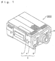
- the projection-type display apparatus 1000 has a rectangular outer casing 2, and the outer casing 2 is basically comprised of an upper case 3, a lower case 4, and a front case 5 defining the front face of the apparatus.
- the leading end potion of the projecting lens unit 6 is protruding from the centre of the front case 5.
- Fig. 2 illustrates the positional relationship of the components within the outer casing 2 of the projection-type display apparatus 1000.
- An electric power source unit 7 is disposed at the rear of the outer casing 2.
- a light source lamp unit 8 is disposed adjacent the electric power source unit 7 toward the front of the apparatus.
- An optical unit 9 is disposed adjacent the inner end of the projecting lens unit 6 which is disposed at the centre front of the optical unit 9.
- An interface board 11 is positioned at one side of the optical unit 9.
- the interface board 11 is mounted with an input/output interface circuit facing toward the front and rear sides of the apparatus.
- a video board 12 is mounted with a video signal processing circuit parallel to the interface board 11.
- a control board 13 is disposed above the light source lamp unit 8 and optical unit 9 for driving and controlling the apparatus.
- Speakers 14 R and 14L are disposed at the front right and left corners of the apparatus.
- a suction fan 15A for cooling is disposed at the centre of the upper side of the optical unit 9, and a circulating fan 15B for cooling circulation is disposed at the centre of the bottom side of the optical unit 9.
- An exhaust fan 16 is positioned at the side of the apparatus adjacent to the rear of the light source lamp unit 8.
- An auxiliary cooling fan 17 for introducing cooling air flow from the suction fan 15A into the electric power source unit 7 is positioned adjacent the edge of the boards 11 and 12 at the electrical power source unit 7.
- a floppy disk drive unit (FDD) 18 is disposed immediately above the electric power source unit 7 at the left side of the apparatus.
- Fig. 3 is a broken away view of the optical unit 9 and projecting lens unit 6.
- upper and lower light guides 901 and 902 support the optical devices other than the prism unit 910 comprising the color synthesizing means.
- the upper light guide 901 and lower light guide 902 are each fixed by fixing screws to the upper case 3 and lower case 4, respectively.
- the upper light guide 901 and lower light guide 902 are also fixed to the side of the prism unit 910 by fixing screws in the same manner.
- the prism unit 910 is fixed by means of a fixing screw to the rear side of a thick head plate 903 which is a die-cast plate.
- the base side of the projecting lens unit 6 is fixed to the front face of head plate 903 by fixing screws.
- Fig. 4 illustrates a schematic of the optical system which is partially incorporated in the optical unit 9.
- the optical system comprises a discharge lamp 81 which is a component of light source lamp unit 8, and an integrator optical system 923 a first lens plate 921 and a second lens plate 922.
- This system also comprises a color separating optical system 924 which separates the white light flux W emitted from the integrator optical system 923 into the red, green, and blue color light flux beams R, G, and B, three liquid crystal light valves 925 R, 925G, and 925B which serve as light valves for modulating the color light flux beams, a prism unit 910 serving as a color synthesizing system for resynthesizing the modulated color fluxes, and a projecting lens unit 6 for performing enlarged projection of the synthesized light flux on the surface of a screen 100. Further, the system includes a light guiding system 927 for guiding the blue colored light flux beam B separated by the color separating optical system 924, to the liquid crystal light valve 925B.
- Lamps such as halogen lamps, metal halide lamps, xenon lamps, and the like can be used as the discharge lamp 81.
- the uniform illumination optical system 923 is provided with a reflecting mirror 931, so as to change the centre optical axis 1a of the emitted light from the integrator optical system 923 toward the front of the apparatus.
- the first and second lens plates 921 and 922 are disposed on either side of this mirror 931 and in an orthogonal relationship.
- the light emitted from the discharge lamp 81 is reflected by the reflecting face 821 of the reflector 82 and irradiated upon the first lens plate 921, lens plate 921 providing parallel light beams, each beam being projected as a secondary light source image upon the incidence plate of each lens of the second lens plate 922, and the light emitted from second lens plate 922 illuminates the image forming range of each light valve 925R, 925G, and 925B.
- the color separating optical system 924 includes a blue green reflecting dichroic mirror 941, a green reflecting dichroic mirror 942, and a reflecting mirror 943.
- the blue green reflecting dichroic mirror 941 the blue light flux beam B and the green light flux beam G in the white light flux beam W is reflected at a right angle, and are directed to the green reflecting dichroic mirror 942.
- the red light flux beam R passes through the mirror 941, is reflected at a right angle by the posterior reflecting mirror 943, and is emitted from the red light flux emitting portion 944 to prism unit 910.
- the blue and green light flux beams B and G are reflected by the mirror 941.
- the green light flux beam G thereof is alone reflected at the green reflecting dichroic mirror 942, and is emitted from the green light flux emitting portion 945 to the prism unit 910.
- the blue light flux beam B which has passed through the mirror 942 is emitted from the blue light flux emitting portion 946 to the light guiding system 927.
- the distances between the white light flux emitting portion of the integrator optical system 923 to each of the light flux emitting portions 944, 945, and 946 of the color separating optical system 924 are the same.
- Focusing lenses 951 and 952 are respectively provided to each of the red light flux and green light flux emitting portions 944 and 945 ensure that incident light is parallel.
- the parallel red and green light flux beams R and G are cast into the crystal light valves 925R and 925G, and modulated adding respective image information.
- the light valves are subjected to switching control according to image information by a driving means (not shown), and accordingly, each of the light fluxes passing through is modulated. Conventional mechanisms can be used as the driving means.
- the blue light flux beam B is led to the corresponding crystal light valve 925B via the light guiding system 927, and similar modulation is performed here in accordance with image information.
- the light valves may be of the type using polysilicone TFT as the switching devices, for example.
- the light guiding system 927 includes a focusing lens 953, an incident side reflecting mirror 971, an emitting side reflecting mirror 972, an intermediate lens 973, and a focusing lens 954 disposed before the liquid crystal panel 925B.
- the distance of the optical path of each color light flux beam, to each of the liquid crystal light valves 925R, 925G, and 925B is longest for the blue light flux beam B, so that the amount of light lost is greatest for blue light. However, the amount of blue light lost can be reduced by means of introducing the light guiding system 927.
- the light flux beams are modulated by passing through the liquid crystal light valves 925R, 925G, and 925B for each color and are directed for synthesis into the color synthesizing optical system 910.
- a prism unit 910 that includes dichroic prisms as described above is used as the color synthesizing optical system.
- the color image resynthesized is subjected to enlarged projection on the surface of a screen 100 by a projecting lens unit 6.
- the projector display apparatus 1 of Fig. 4 has an illumination range on the liquid crystal light valve 925 from the integrator optical system 923 which provides fine adjustment in the vertical ( ⁇ Y direction) and horizontal ( ⁇ Y direction) directions as to the image forming range of the liquid crystal light valve.
- Fig. 5(A) is a model illustration of the relationship between the illumination range B on the liquid crystal light valve 925 from the integrator optical system 923 and the image formation range A of the liquid crystal light valve 925.
- the projecting range of the screen 100 is rectangular, so the image formation range A of the liquid crystal light valve 925 is correspondingly rectangular.
- the illumination range B from the uniform illumination optical system 923 (the range illustrated by imaginary lines in the Figure) is also correspondingly rectangular.
- the image formation range A of the liquid crystal light valve 925 is sized to be distinctly smaller than the illumination range B.
- a margin of a certain width is provided around the image formation range A. Providing for a margin enables for the display range A to always be disposed within the illumination range B, even when the image formation position of the illumination range changes due to a margin of error in positioning the optical parts such as each of the lens plates 921 and 922 integrator optical system 923.
- the lens plates 921 and 922 are arranged to enable fine adjustment of the attachment position thereof in vertical and horizontal directions following a plate perpendicular to the optical axis 1a, by a position adjusting mechanism.
- a leaf spring and position adjusting screw can be used as the position adjusting mechanism.
- Figs. 6(A) and (B) are sectional views of a mechanism for providing fine adjustment of the attachment position of the lens plate 921 in the left and right directions.
- Fig. 6(B) is a cross sectional diagram following the line SS in Fig 6(A). As shown in the diagrams, the position adjusting mechanism 700 is provided at the upper and lower light guides 901 and 902.
- a pair of right and left walls 711 and 712 extending in the vertical direction following a plate vertical to the optical axis 1a, a base wall 713 connecting the lower edges of the vertical walls 711 and 712, and an upper wall 714 connecting the upper edges of the vertical walls 711 and 712, are formed by the upper and lower light guides 901 and 902, with the lens plate 921 being surrounded by the walls 711 - 714.
- the bottom end of the lens plate 921 is inserted into a holding groove 715 which is formed in the base wall 713.
- the lower portion of the lens plate 921 is pressed toward the upstream direction of the optical path (Z direction) by a fixed spring 717 which is mounted by a screw 716 to the base wall 713.
- the upper portion of the lens plate 921 is pressed in the same direction by a fixed spring 719 which is mounted by a screw 718 to the upper wall 714.
- the upper portion of the lens plate 921 contacts a protruding portion 710 which is provided to the upper wall 714. Accordingly, the lens plate 921 is supported by one of the vertical walls 711, via an alignment spring 720.
- the lens plate 921 is pressed toward one of the vertical walls 711, by an adjusting screw 721 which is provided at the other vertical wall 712.
- the attachment position of the lens plate 921 can be moved only in the left and right directions ( ⁇ X direction) by means of adjusting the amount of adjustment of the adjusting screw 721.
- the adjusting screw 721 can be tightened or loosened to provide fine adjustment of the attachment position of the lens plate 921 in the left and right direction, thus shifting the position of the illumination range B sideways, and as shown in Fig. 5(C), the illumination range B is made to encompass the image formation range A.
- an alignment spring 720 comprising a generally L shaped leaf spring is used.
- the adjusting screw 721 presses the approximate centre portion of the side of the lens plate 921 on the side of the vertical wall 712. Accordingly, uniform movement of the lens plate 921 can be realised with few parts.
- an adjustment screw and alignment spring can be provided at the upper wall 714 and lower wall 713, to facilitate adjustment, similar to that described in Figures 6(A) and (B). Accordingly, detailed description thereof will be omitted.
- adhesive agent is injected from adhesive agent injection holes 904a, 904b, 905a, and 905b (shown in Fig. 3) provided in the upper light guide 901, thus fixing the lens plates 921 and 922.
- Such fixing is not necessarily required, but is advantageous as it can ensure the prevention of shifting of the attachment position of the lens plates 921 and 922 due to external shock.
- an adjustment screw and alignment spring are not provided directly to the upper and lower light guides 901 and 902, and instead a separate lens holder is used.
- the fine adjustment in the left and right directions can be made either automatically or manually, by measuring the illuminance on the area of the image formation range A on the liquid crystal light valve 925G.
- the illumination region B is shifted to the left, and the illuminance of the image formation range A on the right side of the liquid crystal light valve 925G is low.
- the attachment position of the lens plate 921 should be shifted to the left or right ( ⁇ X direction) until the right and left illuminance P1 and P2 of the image formation range A are of a constant value.
- this adjusting method requires that a constant value be set beforehand, which creates difficulty in dealing with a situation where the light source has been changed to such with low luminosity.
- the fine adjustment in the left and right directions can be performed automatically or manually, by means of setting the liquid crystal light valve 925G to transmit illumination light, and measuring the illuminance of the area around the projected image when the image is projected on the screen 100.
- the projected image B is not projected to the left edge of the range A' to which the image should be projected, as illustrated in Fig. 5(D). Accordingly, illuminance of the left edge becomes low.
- the illuminance Q1 and Q2 of the left and right portions of the range A' to which the image should be projected is measured, and fine adjustment can be made by means of a method similar to the aforementioned method wherein illuminance measurement is made on the liquid crystal light valve 925G.
- the attachment position of the lens plate 921 is shifted to the left and right until the value of the illuminance Q1 and Q2 becomes constant, or the attachment position of the lens plate 921 is shifted to the left and right until the value of the illuminance Q1 and Q2 becomes equal, or further, the attachment position of the lens plate 921 is shifted to the left and right until the sum value of the illuminance Q1 and Q2 becomes maximal.
- situations where the light source has been changed to such with low luminosity can be dealt with easily by shifting the attachment position of the lens plate 921 to the left and right until the value of the illuminance Q1 and Q2 becomes equal or until the sum value of the illuminance Q1 and Q2 becomes maximal.
- Fine adjustment in the up and down directions can be performed automatically or manually, by measuring the illuminance at the upper and lower portion of the image forming range A, or the illuminance at the upper and lower portion of the projected image.
- the attachment position of the lens plate 922 should be shifted in the vertical direction until the illuminance of two spots become a constant value, the same as with horizontal fine adjustment.
- situations where the light source has been changed to such with low luminosity can be dealt with easily by shifting the attachment position of the lens plate 922 up and down until the illuminance of the two spots becomes equal or until the sum value of the two spots becomes maximal.
- Fine adjustment of the integrator optical system 923 may be performed using the other liquid crystal light valves 925R or 925B instead of the liquid crystal light valve 925G.
- the first lens plate 921 and the second lens plate 922 may be moved simultaneously, but a sequential attachment position fine adjustment method may be used.
- the first lens plate 921 is first moved in the left and right directions to perform fine adjustment in the horizontal direction
- the second lens plate 922 is first moved in the up and down directions to perform fine adjustment in the vertical direction.
- similar adjustment can be made wherein fine adjustment is made in the vertical direction, following fine adjustment in the horizontal direction.
- first lens plate 921 is first moved in the left and right directions to perform fine adjustment
- second lens plate 922 in the up and down directions, but these directions may be reversed.
- only one of the first and second lens plates 921 and 922 can be made to be subjected to fine adjustment.
- attachment position of the first and second lens plates 921 and 922 can be made to be adjustable in any direction intersecting the optical axis.
- First integrator lens Second integrator lens (1) Horizontal Vertical (2) Vertical Horizontal (3) Fixed (non-adjustable) Vertical, Horizontal, or arbitrary (4) Vertical, Horizontal, Fixed (non-adjustable) or arbitrary
- the margin to be provided around the image formation area A can be extremely small, thus providing for increased effectiveness of the usage of illumination light and consequently increasing the brightness of the projected image.
- the invention prevents problems such as shadows forming on the edge of the projected image.
- the illumination range B of the integrator optical system 923 shifts from the image formation area A of the liquid crystal light valve is due to the margin of error of the attachment angle of the reflecting surface of the reflecting mirrors disposed in the optical paths of the light fluxes of each color.
- the attachment angle of the reflecting surface of the reflecting mirror to the optical axis is 45°, but when this angle is shifted, there are cases wherein a portion of the image formation area A may shift out of the illumination range B, as shown in Fig. 5(B). Further, as shown in Figs.
- fine adjustment of the integrator optical system 923 is performed with the liquid crystal light valve 925G as a standard reference.
- the attachment angles of the reflecting surfaces of the mirrors 943, 972, and 971 shown in Fig. 4 are not 45° relative to the optical axis, the illumination ranges of each will be offset as to the image forming area of the liquid crystal light valves 925R and 925B.
- the focusing lens 953 and the intermediate lens 973 are not attached to the predetermined attachment positions, the illumination range will be offset as to the image forming area of the liquid crystal light valve 925B.
- the angle of the reflecting surface of the mirror 943 which reflects the red light flux R toward the liquid crystal light valve 925R and the mirror 972 which reflects the blue light flux B toward the liquid crystal light valve 925B as shown in Fig. 4 can be subjected to fine adjustment as to the incident optical axis around an axial line (following the arrows in Fig. 4) vertical to a plane including the incident optical axis and reflected optical axis.
- An angle adjusting mechanism for this reflecting mirror attachment angle can include a leaf spring and angle adjusting screw similar to that of the above described position adjusting mechanism for the integrator optical system 923.
- Figs. 8 (A) - (C) illustrate an example of a mechanism for performing fine adjustment of the attachment angle of the reflecting mirror 972.
- Fig. 8(A) illustrates the holder plate 740 which holds the reflecting mirror 972.
- Fig. 8(B) illustrates the mechanism for performing fine adjustment of the attachment angle of the reflecting mirror 972 from the side of the upper light guide 901, and
- Fig. 8(C) illustrates the mechanism for performing fine adjustment of the attachment angle of the reflecting mirror 972 from the T-T cross-sectional portion in Fig. 8(B).
- the angle adjustment mechanism 730 has a holder plate 740, and the lower portion of the reflecting mirror 972 is held from the side thereof opposite to the side of the reflecting surface, by means of the holding members 746a and 746b provided at this holder plate 740. Also, the upper portion of the reflecting mirror 972 is fixed to the holder plate 740 by a clip 748. An axial portion 741 extends vertically and is formed at the central portion of the surface of this holder plate 740. This axial portion 741 is rotatably supported by the lower light guide 902. Accordingly, the reflecting mirror 972 can be rotated around the axial line 1b of the axial portion 741 via the holder plate 740, by only a predetermined amount.
- a spring holder 744 is provided at the other side portion of the holder plate 740, and the first fulcrum 742a of the alignment spring 742 is inserted into this spring holder 744.
- the fulcrums 742b and 742c of the alignment spring 742 contact with a supporting portion 749 provided at the lower light guide 902. Accordingly, the holder plate 740 is supported at the lower light guide 902 via the alignment spring 742.
- the spring holder 744 of the holder plate 740 is pressed in the direction of the arrow G in the Figure by means an adjusting screw 743 provided at a plate 770 fixed to the lower light guide 902 by a screw 771.
- the angle of the reflecting surface of the reflecting mirror 972 can be changed so that the incident angle of the incident light to the reflecting mirror 972 is decreased.
- the mechanism for adjusting the angle of the reflecting surface of the other reflecting mirrors can use a mechanism the same as that described above.
- adhesive agent is injected from adhesive agent injection holes 906a, 906b, 907a, and 907b (shown in Fig.3) provided in the upper light guide 901, thus fixing the reflecting mirrors 943 and 972.
- adhesive agent injection holes 906a, 906b, 907a, and 907b shown in Fig.3
- Such fixing is not necessarily required, but is advantageous as it can ensure the prevention of shifting of the reflecting mirrors 943 and 972 due to external shock.
- this fine adjustment can be performed automatically or manually, by means of measuring the illuminance around the image forming range, on the liquid crystal light valve 925R or liquid crystal light valve 925B.
- the attachment angle of each of the reflecting mirrors 943 and 972 should be shifted until the left and right illuminance P1 and P2 of the image formation range A are of a constant value.
- situations where the light source has been changed to such with low luminosity can be dealt with by shifting the attachment angle of each of the reflecting mirrors 943 and 972 until the left and right illuminance P1 and P2 of the image formation range A are equal, or by shifting the attachment angle of the reflecting mirrors 943 and 972 until the sum of the left and right illuminance P1 and P2 of the image formation range A becomes maximal.
- the fine adjustment can be performed automatically or manually, by setting the liquid crystal light valve 925R or liquid crystal light valve 925B to transmit illumination light, and measuring the illuminance of the area around the projected image when the image is projected on the screen 100.
- the illuminance of the left and right sides becomes non-uniform.
- the illuminance of the left and right sides of projected image is measured, and fine adjustment is made in the same manner as with the illumination measurement of the image forming range A, and the attachment angle of the reflecting mirrors 943 and 972 is shifted until the value of the left and right illuminance become constant, or the left and right illuminance become equal, the sum value of the left and right illuminance becomes maximal.
- the reflecting mirrors 943 and 972 may be moved simultaneously.
- a sequential attachment angle adjustment method may be used wherein the reflecting mirror 943 is first moved to perform fine adjustment based on the projected image or image forming range from the liquid crystal light valve 925R, and then the reflecting mirror 972 is moved to perform fine angle adjustment based on the projected image or image forming range from the liquid crystal light valve 925B.
- the attachment angle of the reflecting mirrors 943 and 972 closest to the liquid crystal light valves 925R and 925B can be adjusted, part or all of the other optical components, such as the blue reflecting dichroic mirror 941, green reflecting dichroic mirror 942, or the incident side reflecting mirror 971 may be subjected to fine adjustment of the attachment angles thereof. Also, the position of the intermediate lens 973 or focusing lens 953 may be subjected to adjustment instead of the reflecting mirror 972.
- subjecting the attachment angle of the reflecting mirrors 943 and 972 closest to the liquid crystal light valves 925R and 925B to fine adjusting is most advantageous, from the perspective of apparatus construction and from the perspective of precision of angle adjustment.
- the invention prevents problems such as shadows forming on the edge of the projected image.
- Such an angle adjusting mechanism for optical components such as reflecting mirrors is effective in projection-type display apparatuses which do not use a integrator optical system 923.
- the optical system of the projection-type display apparatus 2000 in accordance with the present invention includes a structure enabling a polarization illumination which comprises an integrator optical system and a polarization beam splitter of a special form.
- the components which are the same as those in the above-described projection-type display apparatus 1000 are provided with the same reference numerals as those given in Figs. 1 - Fig. 8, and detailed description thereof is omitted.
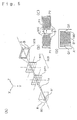
- Fig. 9 illustrates the principal components of the optical system of the projection-type display apparatus 2000 in accordance with present invention, illustrating the construction on an X-Z plane.
- the projection-type display apparatus 2000 in accordance with the present invention is generally comprises a polarization illumination device 1, a color splitting means for splitting the white light flux into three colors, three transmittance-type liquid crystal devices for modulating the light of each color according to display information and forming a display image, a color synthesising means for synthesising the color light of the three colors and forming a color image, and a projecting optical system for projection display of the color image.
- the polarization illumination device 1 comprises a light source portion 10 for emitting random polarization light fluxes in a single direction.
- the random polarization light fluxes emitted from this light source portion 10 are converted into a polarization light flux of almost one type, by a polarization converting device 20.
- the light source portion 10 is generally comprises a light source lamp 101 and a parabolic surface reflector 102.
- the light emitted from the light source lamp is reflected in one direction by the parabolic surface reflector 102, and is cast into the polarization converting device 20 as parallel light flux.
- Light source portion 10 is disposed so that the light source optical axis R of the light source portion 10 is shifted as to the system optical axis L in a parallel manner in the X direction by a constant distance of D.
- the polarization converting device 20 comprises a first optical component 200 and a second optical component 300.
- the first optical component 200 is equivalent to the first lens plate 921 in the above-described projection-type display apparatus 1000, with the cross section on the X-Y plane comprising an matrix-like array of a plurality of rectangular light flux splitting lenses 201.
- the light source optical axis R is disposed so as to intersect the centre of the first optical component 200.
- the light cast into the first optical component 200 is split into a plurality of intermediate light fluxes 202 by the light flux splitting lenses 201.
- a number of focused images equal to the number of light flux splitting lenses are formed at a position at which the intermediate light fluxes are converged within a plane perpendicular to the system optical axis L (the X-Y plane shown in Fig.
- the cross-section of the light flux splitting lenses 201 on the X-Y plane is set so as to be analogous to the form of the image forming range of the liquid crystal light valves.
- the cross-section of the light flux splitting lenses 201 on the X-Y plane is set to be rectangular, since an image forming range is rectangular and long in the X direction on the X-Y plane.
- the second optical component 300 is a complex member that generally comprises a focusing lens array 310, a polarization splitting unit array 320, a selective phase difference plate 380, and a combining lens 390, being positioned near the position at which the focused image from the first optical component 200 is formed, within a plane perpendicular to the system light axis L (the X-Y plane shown in Fig. 9). Also, if the light flux being cast into the first optical component 200 has extremely good parallelism, the focusing lens array 310 can be omitted from the second optical component.
- This second optical component 300 can spatially split each of the intermediate light fluxes 202 into P-polarization light flux and S-polarization light flux, and then emit the P-polarization light flux and S-polarization light flux with the polarization direction of one matching the polarization direction of the other, and leading the light fluxes almost matched in direction to a single illumination range.
- the focusing lens array 310 comprises almost the same structure as that of the first optical component 200.
- the focusing lens array 310 is a matrix array of focusing lenses 311 equal in number to the light flux splitting lenses 201 of the first optical component 200, which focus each of the intermediate light fluxes to a particular spot on the polarization splitting unit array 320.
- each of the focusing lenses be optimised, in accordance with the properties of the intermediate light fluxes 202 formed by the first optical component 200, and wherein it is ideal that the inclination of the main ray of the light incident to the polarization splitting unit array 320 be parallel to the system optical axis L.
- an object exactly identical to the first optical component 200 can be used for the focusing lens array 310, or a focusing lens array that comprises focusing lenses analogous to the form of the light flux splitting lenses 201 on the X-Y plane can be used as the focusing lens array.
- first optical component 200 is used for the focusing lens array 310.
- the focusing lens array 310 may be separated from the polarization splitting unit array 320 (to the side closer to the first optical component 200).
- the polarization splitting unit array 320 comprises a plurality of polarization splitting units 330 arrayed on a matrix form.
- the arraying of the polarization splitting units 330 corresponds with the lens properties of the light flux splitting lenses 201 of the first optical component 200, and the arraying thereof.
- concentric light flux splitting lenses 201 which have all of the same lens properties are used. These light flux splitting lenses are arrayed in an orthogonal matrix form to form the first optical component 200.
- the polarization splitting unit array 320 comprises polarization splitting units 330 arrayed in an orthogonal matrix form, all in the same direction.
- polarization splitting unit array 320 that comprises polarization splitting units which are long and thin in the Y direction and arrayed on the X direction, from the perspective of reducing light lost at the surface between the polarization splitting units, and also from the perspective of facilitating manufacturing costs of the polarization splitting unit array.
- the polarization splitting units 330 are integral having a pair of polarization light splitting surface 331 and reflecting surface 332 within, and spatially splitting each of the intermediate light fluxes cast into the polarization splitting unit into P-polarization light flux and S-polarization light flux.
- the cross-section form of the polarization light splitting units 330 on the X-Y plane is analogous with the cross-section form of the light flux splitting lenses 201 on the X-Y plane, i.e., a rectangular form which is long in the width direction. Accordingly, the polarization light splitting surface 331 and reflecting surface 332 are lined up in the sideways direction (X direction).
- the polarization light splitting surface 331 and reflecting surface 332 are disposed such that the polarization light splitting surface 331 is at an inclination of approximately 45° to the system optical axis L, the reflecting surface 332 is parallel with the polarization splitting surface, and further, the area of the polarization light splitting surface 331 being projected upon the X-Y plane (equal to the area of the later-described P emission plane 333) is equal to the reflecting surface 332 being projected upon the X-Y plane (equal to the area of the later-described S emission plane 334) is equal.
- the width Wp upon the X-Y plane of the range at which the polarization light splitting surface 331 extends and the width Wm upon the X-Y plane of the range at which the reflecting surface 332 extends are equal.
- the polarization light splitting surface 331 can be formed of a dielectric multi-layer film
- the reflecting surface 332 can be formed of a dielectric multi-layer film or aluminum film.
- Incident light to the polarization splitting units 330 is split at the polarization light splitting surface 331 into P polarization light flux 335 which passes through the polarization light splitting surface 331 without changing direction and S polarization light flux 336 which is reflected at the polarization light splitting surface 331 and changes direction toward the reflecting surface 332.
- the P polarization light flux 335 is emitted from the polarization light splitting units without change via the P emission plane 333, and the S polarization light flux 336 changes direction again at the reflecting surface 332.
- the S polarizatoin light flux 336 is the state thereof becoming almost parallel with the P polarization light flux 335, and is emitted from the polarization splitting units via the S emission plane 334.
- the random polarization light flux cast into the polarization splitting unit 330 is split into two types of polarization light fluxes, the P polarization light flux 335 and S polarization light flux 336.
- the P and S polarization light fluxes 335 and 336 have differenct polarization directions, and are emitted from different positions on the polarization splitting units (P emission plane 333 and S emission plane 334) toward the same general direction. Since the polarization splitting units operate as described above, it is necessary to guide each of the intermediate light fluxes 202 to the range where the polarization light splitting surface 331 extends within the polarization splitting units 330.
- each of the focusing lenses 311 of each of the polarization light splitting surface 331 and the lens properties of each of the focusing lenses 311 are set so that the intermediate light fluxes are cast to the centre portion of the polarization light splitting surface within the polarization splitting units.
- the focusing lens array 310 is positioned in a state shifted in the X direction as to the polarization splitting unit array 320 by a distance corresponding to 1/4 of the width W of the polarization splitting units, so that the centre axis of each of the focusing lenses is positioned at the centre portion of the polarization light splitting surface 331 within the polarization splitting units 330.
- a selective phase difference plate 380 that comprises methodically arrayed 1/2 phase difference plates is disposed on the emitting side of the polarization light splitting unit array 320.
- 1/2 phase difference plates are arrayed only at the portion of the P emission plane 333 of the polarization splitting units 330 of the polarization splitting unit array 320, and 1/2 phase difference plates are not provided at the S emission plane 334 portion. Because of the position of the 1/2 phase difference plates, the P polarization light fluxes emitted from the polarization splitting units 330 receive the rotational effects of the polarization direction when passing through the 1/2 phase difference plates and are converted into S polarization light fluxes.
- Combining lens 390 is disposed at the emitting side of the selective phase difference plate 380, and the light flux arranged to be S polarization light flux by the selective phase difference plate 380 is led to the illumination range of each liquid crystal device by the combining lens 390, and is superimposed on the illumination range.
- This combining lens 390 is equivalent to the second lens plate 922 in the above-described projection-Type display apparatus 1000.
- the combining lens 390 does not have to be a single lens member, and instead can be a collection of a plurality of lenses, as with the first optical component 200 of the second lens plate 922 in the projection-type display apparatus 1000.
- the intermediate light fluxes 202 split by the first optical component 200 i.e., the image plane cut out by the light flux splitting lenses 201 are superimposed on the illumination range by the second optical component 300.
- the random intermediated light fluxes are spatially split by the encountered polarizartion splitting unit array 320, and converted into polarization light flux of almost one type upon passing through the selective phase difference plate 380. Accordingly, the image forming range of the liquid crystal light valve is illuminated almost uniformly by polarization light flux of almost one type.
- the polarization illumination device 1 in accordance with the present invention is advantageous in that the random intermediate light fluxes emitted from the light source portion 10 are converted into polarization light flux of almost one type by means of the polarization converting device 20 that comprises a first optical component 200 and a second optical component 300.
- the image forming range of the liquid crystal light valve is illuminated almost uniformly by the light flux with matched polarization direction.
- almost all of the light emitted from the light source portion can be introduced to the image forming range of the liquid crystal light valves since there is very little light loss in the process of generating polarization light flux. Accordingly, the invention provides the advantage therein of extremely high light usage efficiency.
- the focusing lens array 310, polarization splitting unit array 320, selective phase difference plate 380, and combining lens 390 of the second optical component 300 are optically integrated, which lessens light loss at the surfaces thereof and increases light usage efficiency even more.
- the light flux splitting lenses 201 of the first optical component 200 are rectangular and long in the width direction, and at the same time, of a form which splits the two types of polarization light fluxes emitted from the polarization splitting unit array 320 in the sideways direction X direction).
- the illumination efficiency light usage efficiency
- the overall width of the light flux subsequent to splitting is increased twofold, and the optical system accordingly becomes large.
- a plurality of fine focused images are formed by means of the first optical component 200, and the space without light generated in the forming processes is optimally used for placing the reflecting surface 332 of polarization splitting units 330 in that space, thus absorbing the sideways spreading of the light flux due to splitting into the two polarization light fluxes, so that the width of the overall light flux does not spread, consequently providing the advantage that a small optical system can be realised.
- a type of liquid crystal device which modulates one type of polarization light flux. Accordingly, if a conventional illumination device is used and random polarization light flux is introduced to the liquid crystal device, approximately half of the light of the random polarization light flux is absorbed by the polarization plate (not shown) and is changed into heat, resulting in problems such as poor efficiency of light usage. Also a large and noisy cooling device is necessary to suppress the heat generated by the polarization plate. However, these problems have been improved greatly by the projection-type display apparatus 2000 in accordance with the present invention.
- rotation effect of the polarization surface by the 1/2 phase difference plate is provided to one of the polarization light fluxes, e.g., to only the P-polarization light flux, thus aligning this light flux with the other polarization light flux, e.g., the S-polarization light flux. Consequently, polarization light flux of almost one type with aligned polarization direction is introduced to the three liquid crystal light valves 925R, 925G, and 925B, the polarization plate absorbs very little light, and accordingly, efficiency of the light usage is improved and a bright projected image is obtained.
- the polarization illumination device 1 spatially splits two types of polarization light flux in the sideways direction (X direction). Accordingly, light is not wasted, and the arrangement is advantageous for illuminating the liquid crystal devices that are rectangular and long in the width direction
- the polarization illumination device 1 in accordance with the present embodiment, spreading of the width of the light flux emitted by the polarization splitting unit array 320 is suppressed, even though a polarization conversion optical component is incorporated into the structure. This indicates that there is practically no light incident to the liquid crystal devices having a great angle, upon illumination of the liquid crystal devices. Accordingly, a bright projection image can be produced even without using an extremely wide-diameter projection lens with a small f-stop number. As a result, a projection-type display apparatus that is small in size can be provided.
- placing at least one of the first optical component 200 and second optical component 300 contained in the polarization illumination device 1 so that the position thereof is adjustable in the direction orthogonally intersecting the light axis L enables fine adjustment of the illumination range of each of the liquid crystal light valves 925R, 925G, and 925B toward the front, rear, left, and right directions, thus facilitating positioning of the image forming range of each liquid crystal device within the illumination range at all times.
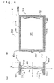
- FIGs 11(A) and (B) are sectional views illustrating an example of a mechanism for making fine adjustment of the attachment position thereof in the vertical direction.
- Fig. 11(B) is a cross-sectional view following the line V-V in Fig 11(A). As shown in the diagrams, the position adjusting mechanism 750 is provided above and below.
- a pair of right and left vertical walls 761 and 762 that extend in the vertical direction and follow a plate vertical to the optical axis 1a, a base wall 763 connecting the lower edges of the vertical walls 761 and 762, and an upper wall 764 connecting the upper edges of the vertical walls 761 and 762, are formed by the upper and lower light guides 901 and 902, with the second optical component 300 being surrounded by the walls 761 - 764.
- the second optical component 300 is pressed against the other vertical wall 762 by a fixing spring 769 mounted between the one vertical wall 761, which defines the left and right ( ⁇ X direction) attachment position.
- the bottom end of the second optical component 300 is inserted into a holding groove 768 which is formed in the base wall 763.
- the lower portion of the second optical component 300 is pressed toward the upstream direction of the optical path (-Z direction) by a fixed spring 783 mounted by a screw 781 to the base wall 713.
- the upper portion of the second optical component 300 is pressed in the same direction by a fixed spring 782 mounted by a screw 780 to the upper wall 764. Further, the upper portion of the second optical component 300 contacts a protruding portion 767 provided at the upper wall 764.
- the Z direction of the attachment position of the second optical component 300 is thereby defined.
- the second optical component 300 is supported by the base wall 763, via an alignment spring 765, and is pressed downwards (+ Y direction) by an adjusting screw 766 provided at the upper wall 764.
- the second optical component 300 can be moved in the up and down directions ( ⁇ Y direction) by adjusting the adjusting screw 766.
- the adjustment screw 766 can be tightened or loosened thus providing fine adjustment in the vertical direction of the attachment position of the second optical component 300.
- the illumination region B is shifted lengthwise and the illumination region B is disposed within the image forming range A.
- adhesive agent is injected from adhesive agent injection holes 908a and 908b provided in the upper light guide 901, to fix the second optical component 300.
- Such fixing is not necessarily required, but is advantageous since it can ensure the prevention of the attachment position of the second optical component 300 from shifting due to external shock.
- a mechanism for providing fine adjustment of the attachment position of the first optical component 200 and second optical component 300 in the left and right directions ( ⁇ X direction), can include a position adjusting mechanism provided with an adjusting screws and alignment spring, as shown in Fig. 6.
- an adjustment screw and alignment spring do not have to be provided directly to the upper and lower light guides 901 and 902, are instead a separate lens holder can be used.
- the position adjusting mechanism of each of the above-described optical devices, the adjustment method thereof, and the effects obtained by adjusting the illumination range are the same as those of the above-described projection-type display apparatus 1000.
- providing fine adjustment of the attachment position of the first optical component 200 and second optical component 300 obviates the need to provide a wide margin around the image formation area of the liquid crystal devices, as with conventional art, taking shifting of the illumination range into consideration. Accordingly, the margin to be provided around the image formation area can be extremely small, thus increasing the effectiveness of the illumination light usage and consequently increasing the brightness of the projected image.
- the problem of a portion of the image formation area of the liquid crystal device extending beyond the illumination range of the polarization illumination device can be obviated, by providing fine adjustment of the attachment angle of each of the above optical components.
- the invention prevents problems such as shadows forming on the edge of the projected image.
- the focusing lens array 310, polarization splitting unit 320, selective phase difference plate 380, and combining lens 390, of the second optical component 300 are optically integrated, which lessens light loss occurring at the surfaces thereof, but these do not necessarily have to be integrated. In the event that these are not integrated, simply adjusting the position of the focusing lens 310 enables adjusting of the formation position of the illumination range to be adjusted.
- the illumination range of the liquid crystal device of the polarization illumination device 1 shifts related to the image forming range of the liquid crystal device because of the margin of error of the attachment angle of the reflecting surface of the reflecting mirrors placed in the optical paths of the light fluxes of each color.
- the attachment angle of the reflecting surface of the reflecting mirror to the optical axis is 45°, but when this angle is shifted, a portion of the image formation area can shift out of the illumination range, as shown in Figs. 7(A) and (B), possibly resulting in warping of the illumination range, which causes the illumination range to shift out of the image forming range of the liquid crystal device. Also, if there is such warping in the illumination range occurs, the illuminance at the left side and the right side of the illumination range become uneven, which prevents the advantages of using the polarization illumination device 1.
- the projection-type display apparatus 2000 of the present embodiment not only provides for the aforementioned fine adjustment of each of the optical components of the aforementioned polarization illumination device 1, but also the angles of the reflecting surfaces of the reflecting mirrors 943 and 972 which are disposed in the optical paths of the light fluxes of each color can be subjected to fine adjustment as to the incident optical axis around an axial line (following the arrows in Fig. 9) vertical to a plane including the incident optical axis and reflected optical axis. Also, the arrangement may be such that the attachment position of the intermediate lens 973 attached between the reflecting mirrors 971 and 972 can be adjusted vertically and horizontally. An angle adjusting mechanism for the attachment angle of the reflecting surface of the reflecting mirror, is described with reference to Fig. 8.
- transmittance-type liquid crystal light valves are used for the liquid crystal light valves 925R, 925G, and 925B in the above-described two examples
- the present invention can also be applied to projection-type display apparatuses using reflectance-type liquid crystal devices, instead. Accordingly, the following is a description of one example of a projection-type display apparatus using reflectance-type liquid crystal light valves instead of transmittance-type liquid crystal light valves in the above-described projection-type display apparatus 2000.
- the components which are the same as those in the above-described projection-type display apparatus 2000 are provided with the same reference numerals as those of Fig. 9 - Fig. 11, and detailed description thereof is omitted.
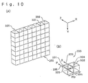
- Fig. 12 shows the principal components of the optical system of the projection-type display apparatus 3000 in accordance with the present invention.
- Fig. 12 is a cross-sectional view on the X-Z plane passing through the centre of the second optical component 300.
- the polarization beam splitter 400 comprises a prism having an S-polarization light flux reflecting surface 401 which reflects S-polarization light flux at approximately 45° and allows transmittance of P-polarization light flux. Since the light flux emitted from the second optical component 300 is light flux which has been converted in one type of polarization direction, almost all of the light flux is either reflected or transmitted by the polarization beam splitter 400.
- the light flux emitted from the second optical component 300 is S-polarization light flux, this S-polarization light flux being bent 90° by the S-polarization light flux reflecting surface 401 and cast into a prism unit 500 wherein dichroic films have been adhered one to another in an X-like form, wherein the light flux is separated into the three colors, R, G, and B.
- Each of the separated light components is cast into reflectance-type liquid crystal devices 600R, 600G, and 600B, which are provided following the three sides of the dichroic prism 500.
- the light flux cast into the reflectance-type liquid crystal devices 600R, 600G, and 600B is modulated by the reflectance-type liquid crystal devices 600R, 600G, and 600B.
- Fig. 13 illustrates an example of the reflectance-type liquid crystal devices 600R, 600G, and 600B.
- the reflectance-type liquid crystal devices 600R, 600G, and 600B are active-matrix type liquid crystal devices, wherein TFT switching devices are connected to each of the devices arrayed in a matrix, and a liquid crystal layer 620 is sandwiched in between a pair of substrates, 610 and 630.
- the substrate 610 is formed of silicone, and formed to a portion thereof is the source 611 and drain 616.
- a source electrode 612 and drain electrode 617 formed of an aluminum layer channels formed of silicone dioxide layer 613, gate electrodes formed of a silicone layer 614 and a tantalum layer 615, inter-layer insulating film 618, and a reflectance picture element electrode 619 formed of an aluminum layer, wherein the drain electrode 617 and reflectance picture element electrode 619 are electrically connected by a contact hole H. Since the reflectance picture element electrode 619 is non-transparent, it can be laid over the gate electrode, source electrode 612, and drain electrode 617 via the inter-layer insulating film 618. Since the distance X between the neighbouring reflectance picture element electrodes 619 can be quite small, the opening ratio can be great, so that the projected image can be bright.
- holding capacity is provided that comprises of drain 616, silicone dioxide layer 613', silicone layer 614', and tantalum layer 615'.
- an opposing electrode 631 which is formed of ITO is disposed on the surface of one side of the opposing substrate 630 adjacent to the liquid crystal layer 620.
- An anti-reflection layer 632 being disposed on the other surface.
- the liquid crystal layer 620 of the present embodiment is such that the liquid crystal molecules 621 are vertically aligned when OFF - voltage is applied (OFF - state), and the liquid crystal molecules 621 exhibit super homeotropic orientation and twist 90° when on - voltage is applied (ON - state). Accordingly, as shown in Fig.
- the S-polarization light flux which is cast to the reflectance-type liquid crystal devices 600R, 600G, and 600B from the polarization beam splitter 400 when OFF - voltage is applied is returned from the reflectance-type liquid crystal devices 600R, 600G, and 600B to the polarization beam splitter 400 without any change in the polarization direction thereof.
- the S - polarization light flux is not reflected by the S-polarization light flux reflecting surface 401 and does not reach the side of the projecting lens unit 6.
- the S-polarization light flux cast to the reflectance-type liquid crystal devices 600R, 600G, and 600B from the polarization beam splitter 400 when ON - voltage is applied becomes P-polarization light flux with the polarization direction thereof changed due to twisting of the liquid crystal molecules 621, is transmitted through the S-polarization light flux reflecting surface 401, and is subsequently projected onto the screen 100 via the projection lens unit 6.
- the light flux modulated by the reflectance-type liquid crystal devices 600R, 600G, and 600B is synthesised by the prism unit 500, and is subsequently projected onto the screen 100 via the polarization beam splitter 400 and projection lens unit 6.
- making the attachment position of the first optical component 200 and second optical component 300 of the polarization converting device 20 of the polarization illumination device 1 to be movable vertically and horizontally in directions orthogonally intersecting the light axis enables the illumination range of the liquid crystal devices of this polarization illumination device 1 to be adjusted into the appropriate position and form.
- the position adjusting mechanism of the above-described position-adjustable optical components, the adjustment method thereof, and the effects and so forth obtained by adjusting the illumination range are the same as those of the above-described projection-type display apparatus 2000.
- the projection-type display apparatus 3000 of the present embodiment not only can the same effects of the above other two projection-type display apparatuses described above be obtained other than by adjustment of the illumination area, but the following effects can also be obtained.
- the color separating means and the color synthesising means are comprised in a single prism unit, the optical path can be made to be extremely short. Also, since the opening ratio of the liquid crystal device is great, loss of light can be prevented. Accordingly, a bright projected image can be obtained even without using a projecting lens with a great diameter. Further, by using the first optical component and second optical component, polarized light flux which is uniform in brightness and without irregularity can be obtained as illumination light, and thus a projected image can be obtained which is extremely uniform over the display surface and the overall projection surface, is also extremely bright.
- reflectance-type liquid crystal devices 600R, 600G, and 600B are used as reflectance-type modulating means
- reflectance-type modulating means other than liquid crystal devices can also be employed, and the structure thereof, the materials of each component, and the operation mode of the liquid crystal layer 620 are not limited to that of the above-described example.
- the prism 402 of the polarization beam splitter 400 and the prism 501 which comprises the prisms unit 500 as a single prism light loss at these borders, further increasing efficiency of light usage.
- the arrangement of the optical system is not restricted to the above described examples either, and altering the arrangement of these does not necessarily obviate the advantage of the present invention.
- projection-type display apparatuses there are rear projection type display apparatuses which project images from the opposite side of the observation side of the screen, in addition to the frontal projection type display apparatuses described in the present embodiment wherein images are projected from the observation side of the screen.
- the present invention is also applicable to such rear-projection types.
- the projection-type display apparatuses in accordance with the present invention provide fine adjustment of the attachment position of each of the lens plate of the integrator optical system.
- the present invention provides fine adjustment of the attachment angle of the reflecting means provided on the optical path extending from the light source to the modulation means. Accordingly, the formation position of the illumination range of illuminating light illuminating the modulating means can be subjected to fine adjustment in the direction vertical to the optical axis, and thereby the image forming position of the illumination range can be set to include the image forming range of the modulation means at all times.
- the illumination range of illumination light is formed so as to include the image forming range, which obviates problems such as shadows forming on the edge of the projected image.
Abstract
Description
- The present invention relates to a projector apparatus which modulates light emitted from a light source in accordance with image signals using modulation means such as liquid crystal light valves or the like, and performs enlarged projection of the light flux following modulation upon a screen via a projecting lens. More particularly, the present invention relates to a structure for a projector apparatus of such a type whereby the image formation range of the modulating means can be illuminated in an appropriate manner.
- A conventional projector apparatus which modulates light flux in accordance with image signals using liquid crystal light valves and performs enlarged projection of the modulated light flux upon a screen is disclosed in Japanese Unexamined Patent Publication No. 3-111806. The projector apparatus disclosed in this Patent Publication is, as shown in Fig. 14, provided with an integrator
optical system 923. The integrator optical system has twolens plates lenses crystal light valve 925. The liquidcrystal light valve 925 serves as a modulation means of the light from the light source. In Fig. 14, the single light flux emitted from a lightsource lamp unit 8 is separated bylenses 921a into a plurality of separate intermediate light fluxes which are transmitted vialenses 922a. The total light flux is superimposed on the liquidcrystal light valve 925 ofsecond lens plate 922. - Problems occur with projector apparatus of the type illustrated in Fig. 14, in that the image formation range of the liquid
crystal light valve 925 cannot be illuminated accurately. These problems include a reduction in the brightness of the image projected upon the projection surface and the creation of shadows showing up at the edge of the projected image. Accordingly, as illustrated in Fig. 15, a certain margin M is secured around the image formation area A of the liquidcrystal light valve 925,depending on various factors including the positioning precision of the liquidcrystal light valve 925 and thelens plates optical system 923, the margin of error of the focal distance and so forth of thelenses crystal light valve 925 is sized to be distinctly smaller than the illumination range B of light emitted by the light source, so that even in the event that the illumination range B is shifted vertically or horizontally due to the positioning precision of the above-described components, the image formation range A does not extend beyond the illumination range B. This arrangement avoids problems such as the reduction of the brightness of the image projected upon the projection surface, or the creation of shadows showing up at the edge of the projected image. Thus, simply increasing the margin M is sufficient to deal with a wide margin of error in positioning of the above-described components. - On the other hand, in order to increase the brightness of the projected image, it is necessary to increase the usage efficiency of the light which is illuminating the liquid
crystal light valve 925. However, the problem occurs that when the margin M is increased to deal with a wide margin of error in positioning of the above-described components, the usage efficiency of the separated light decreases, and the projected image becomes dark. Accordingly, from this perspective, it is desirable that the margin formed around the display range of the liquid crystal light valve be as narrow as possible. However, if the margin is made narrow, the illumination range misses the image formation range of the liquid crystal light valve, as described above, so that shadows may be formed at the edge of the projected image. - It is an object of the present invention to provide a projector apparatus wherein the margin formed around the image forming range of the liquid crystal light valve is small, and at the same time, capable of increasing the brightness of the projected image without forming shadows at the edge of the projected image.
- In a first aspect the invention provides a projector apparatus, comprising:
- a light source, modulating means for modulating light flux emitted from said light source in accordance with image signals, and projecting means for performing enlarged projection of said light flux modulated by said modulating means upon a projection surface;
- first and second optical components, for splitting the emitted light fluxes from said light source into a plurality of intermediate light flux beams, disposed in the optical path between said light source and said modulating means;
- and wherein at least one of said first and second optical components is arranged so that the position thereof is adjustable in a direction intersecting the optical axis.
-
- The present invention is capable of increasing the usage efficiency of light illuminating the modulating means, and the projected image can be made brighter. Also, fine adjustment of the illumination area of the modulation means can be performed so that the image forming range is positioned within the illumination area, which avoids problems mentioned above such as reduction of the brightness of the image projected upon the projection surface or the creation of shadows at the edge of the projected image, even if the margin formed around the image forming range of the modulation means is made to be small.
- Thus, subsequent to mounting the various components of the optical system, the image forming range of the modulation means is illuminated using the integrator optical system, and in the event that the illumination range is not within the image forming range of the modulation means, the attachment position of the first optical component or the second optical component or the attachment angle of the reflecting means is subjected to fine adjustment, so that the image forming range of the modulation means can be brought to completely within the illumination range. Accordingly, the margin formed around the image forming range of the modulation means can be reduced and still handle the offset between the illumination range and the image formation range caused by the margin of error in the positioning of optical parts.
- Further said second optical component may include a polarisation conversion device which spatially splits each of the plurality of intermediate light beams in to polarization light flux of the same polarization direction, and a combining lens for combining the light beams emitted from said polarization converting device. Accordingly, a bright projected image can be obtained, since the polarized light beams can be used without waste, by using the polarization conversion device.
- By integrating the focusing lens array, the polarization converting device, and the combining lens, loss of light between these optical components can be reduced, thus further improving the usage efficiency of light.
- Reflecting means for bending the optical path may be provided on the optical path extending from the light source to the modulation means. In such cases, any margin of error in the attachment angle of the reflecting means may cause the illumination range to be offset from the image formation range of the modulating means. Accordingly, it is desirable that the attachment or disposition angle of the reflecting means mounted to this position also be adjustable relative to the incident optical axis.
- It is most advantageous, from the perspective of apparatus construction and from the perspective of precision of position adjustment of the illumination range as to the modulation means to make the attachment angle of the reflecting means mounted to the position closest to the modulating means adjustable.
- The above described configuration of the projector apparatus can similarly be applied to projectors capable of projecting colour images. In other words, the present invention can similarly be applied to a projector apparatus comprising a colour separating optical system for separating the light emitted from the light source into a light flux or beam of each colour, a plurality of the modulating means for modulating the light flux of each colour separated by the colour separating optical system, and a colour synthesising system for synthesising the light flux of each colour modulated by the plurality of the modulating means.
- Also, using reflecting type modulation for the modulation and manufacturing the colour separating optical system and the colour synthesising optical system as a single optical system, shortens the optical path, which reduces the size of the projection-type display apparatus.
- Now, with the projector apparatus in accordance with the present invention, in order to make the attachment position of at least one of the first and second optical component to be adjustable in the direction intersecting the optical axis, an adjustment mechanism should be provided at that end. Examples of arrangements for such an adjustment mechanism include a first adjustment mechanism for adjusting the aforementioned first optical component in a first direction orthogonally intersecting with the optical axis, and a second adjustment mechanism for adjusting the aforementioned second optical component in a second direction orthogonally intersecting with the aforementioned optical axis and the aforementioned first direction.
- An adjusting mechanism for adjusting the attachment position of the optical component in a predetermined direction, may include a spring provided to a first side of the optical component for pressing the first side; and a screw is provided to a second side of the optical component opposing the first side thereof, for pressing the second side. By employing such an adjusting mechanism, the lens plate can be moved in the predetermined direction simply by tightening and loosening the screw, which facilitates simple adjustment of the attachment position of the aforementioned lens plate.
- Regarding the adjusting mechanism using the spring and screw, uniform movement of the lens plate can be facilitated with a small number of parts, by using a leaf spring for the spring and arranging the screw to press the approximately centre portion of the second side of the lens plate.
- Further, with the projector apparatus in accordance with the invention, in order to make the angle of the reflecting means positioned in the optical path that causes positional change of the illumination range to be adjustable, an adjustment mechanism should be provided at that end. Such adjustment mechanisms may comprise a holder plate which holds the reflecting means, a screw for adjusting the angle of the reflecting means, and a spring for supporting the holder plate as to a light guide in which the reflection means stored. Such an adjusting mechanism arrangement allows for simple changing of the attachment angle of the reflecting means, simply by adjusting the amount of screwing by the screw.
- Preferred embodiments of the invention will now be described, with reference to the accompanying drawings, in which:
- Fig. 1 illustrates a projection-type display apparatus according to the present embodiment.
- Fig. 2(A) is a broken away top elevational view illustrating the interior construction of the projection-type display apparatus, and (B) is a broken away side elevational view thereof.
- Fig. 3 is a broken away elevational view illustrating the optical unit and projecting lens unit.
- Fig. 4 is a schematic view of the optical system which is incorporated in the optical unit.
- Fig. 5 is a model illustration showing the relationship between the illumination range from the integrator optical system, with the display range of the liquid crystal light valve.
- Figs. 6(A) and (B) are each schematic cross-sectional views of a mechanism for making fine adjustment of the attachment position of the lens plate to the left and right.
- Fig. 7 is an explanatory diagram illustrating the change in form of the illumination range of the integrator optical system from the reflecting surface of the reflecting means.
- Fig. 8(A) - (C) illustrate a mechanism for performing fine adjustment of the attachment angle of the reflecting mirror, wherein (A) is an explanatory diagram of the holder plate, (B) is a plan view of the mechanism for performing fine adjustment, and (C) is a cross-section diagram of the fine adjustment mechanism.
- Fig. 9 is a schematic plan diagram of the principal components of another example of an optical system of the projection-type display apparatus in accordance with the present invention.
- Fig. 10(A) is a perspective view illustrating the polarization splitting unit array shown in Fig. 9, and Fig. 10(B) is an explanatory diagram illustrating the splitting operation of polarization light flux by the polarization splitting unit array.
- Figs. 11(A) and (B) are schematic cross-sectional views of an example of a mechanism for making fine adjustment of the attachment position of the second optical component in left and right directions.
- Fig. 12 is a schematic diagram of the principal components of yet another example of an optical system of the projector apparatus in accordance with the present invention.
- Fig. 13 is an explanatory diagram illustrating the operation of the reflectance-type liquid crystal device shown in Fig. 9.
- Fig. 14 is a schematic drawing illustrating the optical system of a prior art projector display apparatus provided with an integrator optical system.
- Fig. 15 is an explanatory diagram illustrating the relationship between the illumination range on the liquid crystal light valves and the image forming range of the projectior of Fig. 14.
-
- In the following description, the three orthogonally intersecting directions are represented by X, Y, and Z, with Z being the direction of progress of light.
- The projector display apparatus in accordance with the present invention and as described below is constructed such that light flux beams of the colors red, blue, and green are extracted from light emitted from a light source via an integrator optical system and colour separating system. Each of the colour beams is led to a respective liquid crystal light valve for the colour and is modulated according to colour image signals. Following re-synthesising of the colour flux beams after modulation, the colour fluxes are subjected to enlarged projection thereof upon a screen via a projecting lens.
- As shown in Fig. 1, the projection-
type display apparatus 1000 has a rectangularouter casing 2, and theouter casing 2 is basically comprised of anupper case 3, alower case 4, and afront case 5 defining the front face of the apparatus. The leading end potion of the projectinglens unit 6 is protruding from the centre of thefront case 5. - Fig. 2 illustrates the positional relationship of the components within the
outer casing 2 of the projection-type display apparatus 1000. An electricpower source unit 7 is disposed at the rear of theouter casing 2. A lightsource lamp unit 8 is disposed adjacent the electricpower source unit 7 toward the front of the apparatus. Anoptical unit 9 is disposed adjacent the inner end of the projectinglens unit 6 which is disposed at the centre front of theoptical unit 9. - An
interface board 11 is positioned at one side of theoptical unit 9. Theinterface board 11 is mounted with an input/output interface circuit facing toward the front and rear sides of the apparatus. Avideo board 12 is mounted with a video signal processing circuit parallel to theinterface board 11. Acontrol board 13 is disposed above the lightsource lamp unit 8 andoptical unit 9 for driving and controlling the apparatus.Speakers - A
suction fan 15A for cooling is disposed at the centre of the upper side of theoptical unit 9, and a circulatingfan 15B for cooling circulation is disposed at the centre of the bottom side of theoptical unit 9. Anexhaust fan 16 is positioned at the side of the apparatus adjacent to the rear of the lightsource lamp unit 8. Anauxiliary cooling fan 17 for introducing cooling air flow from thesuction fan 15A into the electricpower source unit 7 is positioned adjacent the edge of theboards power source unit 7. - A floppy disk drive unit (FDD) 18 is disposed immediately above the electric
power source unit 7 at the left side of the apparatus. - Fig. 3 is a broken away view of the
optical unit 9 and projectinglens unit 6. As shown, upper and lower light guides 901 and 902 support the optical devices other than theprism unit 910 comprising the color synthesizing means. The upperlight guide 901 and lowerlight guide 902 are each fixed by fixing screws to theupper case 3 andlower case 4, respectively. Also, the upperlight guide 901 and lowerlight guide 902 are also fixed to the side of theprism unit 910 by fixing screws in the same manner. Theprism unit 910 is fixed by means of a fixing screw to the rear side of athick head plate 903 which is a die-cast plate. The base side of the projectinglens unit 6 is fixed to the front face ofhead plate 903 by fixing screws. - Fig. 4 illustrates a schematic of the optical system which is partially incorporated in the
optical unit 9. The optical system comprises adischarge lamp 81 which is a component of lightsource lamp unit 8, and an integrator optical system 923 afirst lens plate 921 and asecond lens plate 922. This system also comprises a color separatingoptical system 924 which separates the white light flux W emitted from the integratoroptical system 923 into the red, green, and blue color light flux beams R, G, and B, three liquid crystallight valves prism unit 910 serving as a color synthesizing system for resynthesizing the modulated color fluxes, and a projectinglens unit 6 for performing enlarged projection of the synthesized light flux on the surface of ascreen 100. Further,the system includes alight guiding system 927 for guiding the blue colored light flux beam B separated by the color separatingoptical system 924, to the liquid crystallight valve 925B. - Lamps such as halogen lamps, metal halide lamps, xenon lamps, and the like can be used as the
discharge lamp 81. The uniform illuminationoptical system 923 is provided with a reflecting mirror 931, so as to change the centreoptical axis 1a of the emitted light from the integratoroptical system 923 toward the front of the apparatus. The first andsecond lens plates - The light emitted from the
discharge lamp 81 is reflected by the reflectingface 821 of thereflector 82 and irradiated upon thefirst lens plate 921,lens plate 921 providing parallel light beams, each beam being projected as a secondary light source image upon the incidence plate of each lens of thesecond lens plate 922, and the light emitted fromsecond lens plate 922 illuminates the image forming range of eachlight valve - The color separating
optical system 924 includes a blue green reflectingdichroic mirror 941, a green reflectingdichroic mirror 942, and a reflectingmirror 943. In the blue green reflectingdichroic mirror 941, the blue light flux beam B and the green light flux beam G in the white light flux beam W is reflected at a right angle, and are directed to the green reflectingdichroic mirror 942. - The red light flux beam R passes through the
mirror 941, is reflected at a right angle by theposterior reflecting mirror 943, and is emitted from the red lightflux emitting portion 944 toprism unit 910. The blue and green light flux beams B and G are reflected by themirror 941. The green light flux beam G thereof is alone reflected at the green reflectingdichroic mirror 942, and is emitted from the green lightflux emitting portion 945 to theprism unit 910. The blue light flux beam B which has passed through themirror 942, is emitted from the blue lightflux emitting portion 946 to thelight guiding system 927. The distances between the white light flux emitting portion of the integratoroptical system 923 to each of the lightflux emitting portions optical system 924 are the same. - Focusing
lenses flux emitting portions light valves light valve 925B via thelight guiding system 927, and similar modulation is performed here in accordance with image information. The light valves may be of the type using polysilicone TFT as the switching devices, for example. - The
light guiding system 927 includes a focusinglens 953, an incidentside reflecting mirror 971, an emittingside reflecting mirror 972, anintermediate lens 973, and a focusinglens 954 disposed before theliquid crystal panel 925B. The distance of the optical path of each color light flux beam, to each of the liquid crystallight valves light guiding system 927. - The light flux beams are modulated by passing through the liquid crystal
light valves optical system 910. Aprism unit 910 that includes dichroic prisms as described above is used as the color synthesizing optical system. The color image resynthesized is subjected to enlarged projection on the surface of ascreen 100 by a projectinglens unit 6. - The
projector display apparatus 1 of Fig. 4, has an illumination range on the liquid crystallight valve 925 from the integratoroptical system 923 which provides fine adjustment in the vertical (± Y direction) and horizontal (± Y direction) directions as to the image forming range of the liquid crystal light valve. - Fig. 5(A) is a model illustration of the relationship between the illumination range B on the liquid crystal
light valve 925 from the integratoroptical system 923 and the image formation range A of the liquid crystallight valve 925. The projecting range of thescreen 100 is rectangular, so the image formation range A of the liquid crystallight valve 925 is correspondingly rectangular. The illumination range B from the uniform illumination optical system 923 (the range illustrated by imaginary lines in the Figure) is also correspondingly rectangular. - As described above, the image formation range A of the liquid crystal
light valve 925 is sized to be distinctly smaller than the illumination range B. A margin of a certain width is provided around the image formation range A. Providing for a margin enables for the display range A to always be disposed within the illumination range B, even when the image formation position of the illumination range changes due to a margin of error in positioning the optical parts such as each of thelens plates optical system 923. - In the present embodiment, as shown in the arrows in the Figure, the
lens plates optical axis 1a, by a position adjusting mechanism. A leaf spring and position adjusting screw can be used as the position adjusting mechanism. - Figs. 6(A) and (B) are sectional views of a mechanism for providing fine adjustment of the attachment position of the
lens plate 921 in the left and right directions. Fig. 6(B) is a cross sectional diagram following the line SS in Fig 6(A). As shown in the diagrams, theposition adjusting mechanism 700 is provided at the upper and lower light guides 901 and 902. A pair of right and leftwalls optical axis 1a, abase wall 713 connecting the lower edges of thevertical walls upper wall 714 connecting the upper edges of thevertical walls lens plate 921 being surrounded by the walls 711 - 714. The bottom end of thelens plate 921 is inserted into a holdinggroove 715 which is formed in thebase wall 713. Also, the lower portion of thelens plate 921 is pressed toward the upstream direction of the optical path (Z direction) by afixed spring 717 which is mounted by ascrew 716 to thebase wall 713. The upper portion of thelens plate 921 is pressed in the same direction by afixed spring 719 which is mounted by ascrew 718 to theupper wall 714. The upper portion of thelens plate 921 contacts a protrudingportion 710 which is provided to theupper wall 714. Accordingly, thelens plate 921 is supported by one of thevertical walls 711, via analignment spring 720. Also, thelens plate 921 is pressed toward one of thevertical walls 711, by an adjustingscrew 721 which is provided at the othervertical wall 712. Thus, the attachment position of thelens plate 921 can be moved only in the left and right directions (± X direction) by means of adjusting the amount of adjustment of the adjustingscrew 721. - As shown in Fig. 5(B), in cases wherein the illumination range B is offset in the horizontal direction as to the image formation range A of the liquid crystal
light valve 925, and part of the image formation range A is not illuminated, the adjustingscrew 721 can be tightened or loosened to provide fine adjustment of the attachment position of thelens plate 921 in the left and right direction, thus shifting the position of the illumination range B sideways, and as shown in Fig. 5(C), the illumination range B is made to encompass the image formation range A. - Also, with the present embodiment, an
alignment spring 720 comprising a generally L shaped leaf spring is used. The adjustingscrew 721 presses the approximate centre portion of the side of thelens plate 921 on the side of thevertical wall 712. Accordingly, uniform movement of thelens plate 921 can be realised with few parts. - As regards a mechanism for providing fine adjustment of the attachment position of the
lens plate 922 in the vertical directions (± Y direction), an adjustment screw and alignment spring can be provided at theupper wall 714 andlower wall 713, to facilitate adjustment, similar to that described in Figures 6(A) and (B). Accordingly, detailed description thereof will be omitted. - Subsequent to fine adjustment of the
lens plates agent injection holes light guide 901, thus fixing thelens plates lens plates - As an alternative,an adjustment screw and alignment spring are not provided directly to the upper and lower light guides 901 and 902, and instead a separate lens holder is used.
- Further, the fine adjustment in the left and right directions (± X direction) can be made either automatically or manually, by measuring the illuminance on the area of the image formation range A on the liquid crystal
light valve 925G. In the structure illustrated in Fig. 5(B), the illumination region B is shifted to the left, and the illuminance of the image formation range A on the right side of the liquid crystallight valve 925G is low. In order to adjust such offset of the illumination range B, the attachment position of thelens plate 921 should be shifted to the left or right (± X direction) until the right and left illuminance P1 and P2 of the image formation range A are of a constant value. However, this adjusting method requires that a constant value be set beforehand, which creates difficulty in dealing with a situation where the light source has been changed to such with low luminosity. - Since there is no need to set a constant value beforehand if the attachment position of the
lens plate 921 is shifted to the left or right until the right and left illuminance P1 and P2 of the image formation range A are of an equal value, a situation where the light source has been changed to such with low luminosity can be dealt with easily. Also, since there is no need to set a constant value beforehand even if the attachment position of thelens plate 921 is shifted to the left or right until the sum of the right and left illuminance P1 and P2 of the image formation range A is maximal, a situation where the light source has been changed to such with low luminosity can be dealt with easily. - Instead of using the method wherein the illuminance in the area of the image formation range A on the liquid crystal
light valve 925G is measured, the fine adjustment in the left and right directions (± X direction) can be performed automatically or manually, by means of setting the liquid crystallight valve 925G to transmit illumination light, and measuring the illuminance of the area around the projected image when the image is projected on thescreen 100. - When projection is made to the
screen 100 in the structure illustrated in Fig. 5(B), the projected image B is not projected to the left edge of the range A' to which the image should be projected, as illustrated in Fig. 5(D). Accordingly, illuminance of the left edge becomes low. Thus, the illuminance Q1 and Q2 of the left and right portions of the range A' to which the image should be projected is measured, and fine adjustment can be made by means of a method similar to the aforementioned method wherein illuminance measurement is made on the liquid crystallight valve 925G. For example, the attachment position of thelens plate 921 is shifted to the left and right until the value of the illuminance Q1 and Q2 becomes constant, or the attachment position of thelens plate 921 is shifted to the left and right until the value of the illuminance Q1 and Q2 becomes equal, or further, the attachment position of thelens plate 921 is shifted to the left and right until the sum value of the illuminance Q1 and Q2 becomes maximal. Also, as described above, situations where the light source has been changed to such with low luminosity can be dealt with easily by shifting the attachment position of thelens plate 921 to the left and right until the value of the illuminance Q1 and Q2 becomes equal or until the sum value of the illuminance Q1 and Q2 becomes maximal. - Fine adjustment in the up and down directions (± Y direction) can be performed automatically or manually, by measuring the illuminance at the upper and lower portion of the image forming range A, or the illuminance at the upper and lower portion of the projected image. In the case of vertical adjustment, the attachment position of the
lens plate 922 should be shifted in the vertical direction until the illuminance of two spots become a constant value, the same as with horizontal fine adjustment. Also, situations where the light source has been changed to such with low luminosity can be dealt with easily by shifting the attachment position of thelens plate 922 up and down until the illuminance of the two spots becomes equal or until the sum value of the two spots becomes maximal. - Fine adjustment of the integrator
optical system 923 may be performed using the other liquid crystallight valves light valve 925G. - When performing fine adjustment, the
first lens plate 921 and thesecond lens plate 922 may be moved simultaneously, but a sequential attachment position fine adjustment method may be used. For example, thefirst lens plate 921 is first moved in the left and right directions to perform fine adjustment in the horizontal direction, and next, thesecond lens plate 922 is first moved in the up and down directions to perform fine adjustment in the vertical direction. Of course, similar adjustment can be made wherein fine adjustment is made in the vertical direction, following fine adjustment in the horizontal direction. - While in the above example, the
first lens plate 921 is first moved in the left and right directions to perform fine adjustment, and thesecond lens plate 922 in the up and down directions, but these directions may be reversed. Further, only one of the first andsecond lens plates second lens plates -
First integrator lens Second integrator lens (1) Horizontal Vertical (2) Vertical Horizontal (3) Fixed (non-adjustable) Vertical, Horizontal, or arbitrary (4) Vertical, Horizontal, Fixed (non-adjustable) or arbitrary - Thus, enabling for fine adjustment of the attachment position of the integrator optical system obviates the need to provide a certain margin around the image formation area A of the liquid crystal light valve wherein shifting of the illumination range is taken into consideration beforehand, as with the conventional art. Accordingly, the margin to be provided around the image formation area A can be extremely small, thus providing for increased effectiveness of the usage of illumination light and consequently increasing the brightness of the projected image.
- In other words, even if the margin is reduced, the problem of a portion of the image formation area A extending beyond the illumination range B as shown in Fig. 5(B) can be obviated, by making fine adjustment of the attachment position of the
lens plates - Further, another reason that the illumination range B of the integrator
optical system 923 shifts from the image formation area A of the liquid crystal light valve is due to the margin of error of the attachment angle of the reflecting surface of the reflecting mirrors disposed in the optical paths of the light fluxes of each color. The attachment angle of the reflecting surface of the reflecting mirror to the optical axis is 45°, but when this angle is shifted, there are cases wherein a portion of the image formation area A may shift out of the illumination range B, as shown in Fig. 5(B). Further, as shown in Figs. 7(A) and (B), this can result in warping of the illumination range B, causing non-uniformity in the illuminance of the left side of the illumination range B and the illuminance of the right side thereof, thus destroying the advantages of using the integratoroptical system 923. - Particularly, with the projection-
type display apparatus 1000 in accordance with the present embodiment, fine adjustment of the integratoroptical system 923 is performed with the liquid crystallight valve 925G as a standard reference. However, if the attachment angles of the reflecting surfaces of themirrors light valves lens 953 and theintermediate lens 973 are not attached to the predetermined attachment positions, the illumination range will be offset as to the image forming area of the liquid crystallight valve 925B. - Now, with the projection-
type display apparatus 1000 in accordance with the present embodiment, in addition to the aforementioned fine adjustment of the integratoroptical system 923, the angle of the reflecting surface of themirror 943 which reflects the red light flux R toward the liquid crystallight valve 925R and themirror 972 which reflects the blue light flux B toward the liquid crystallight valve 925B as shown in Fig. 4 can be subjected to fine adjustment as to the incident optical axis around an axial line (following the arrows in Fig. 4) vertical to a plane including the incident optical axis and reflected optical axis. An angle adjusting mechanism for this reflecting mirror attachment angle, can include a leaf spring and angle adjusting screw similar to that of the above described position adjusting mechanism for the integratoroptical system 923. - Figs. 8 (A) - (C) illustrate an example of a mechanism for performing fine adjustment of the attachment angle of the reflecting
mirror 972. Fig. 8(A) illustrates theholder plate 740 which holds the reflectingmirror 972. Fig. 8(B) illustrates the mechanism for performing fine adjustment of the attachment angle of the reflectingmirror 972 from the side of the upperlight guide 901, and Fig. 8(C) illustrates the mechanism for performing fine adjustment of the attachment angle of the reflectingmirror 972 from the T-T cross-sectional portion in Fig. 8(B). As shown in these diagrams, theangle adjustment mechanism 730 has aholder plate 740, and the lower portion of the reflectingmirror 972 is held from the side thereof opposite to the side of the reflecting surface, by means of the holdingmembers holder plate 740. Also, the upper portion of the reflectingmirror 972 is fixed to theholder plate 740 by aclip 748. Anaxial portion 741 extends vertically and is formed at the central portion of the surface of thisholder plate 740. Thisaxial portion 741 is rotatably supported by the lowerlight guide 902. Accordingly, the reflectingmirror 972 can be rotated around theaxial line 1b of theaxial portion 741 via theholder plate 740, by only a predetermined amount. Also, aspring holder 744 is provided at the other side portion of theholder plate 740, and thefirst fulcrum 742a of thealignment spring 742 is inserted into thisspring holder 744. Thefulcrums alignment spring 742 contact with a supportingportion 749 provided at the lowerlight guide 902. Accordingly, theholder plate 740 is supported at the lowerlight guide 902 via thealignment spring 742. Further, thespring holder 744 of theholder plate 740 is pressed in the direction of the arrow G in the Figure by means an adjustingscrew 743 provided at aplate 770 fixed to the lowerlight guide 902 by ascrew 771. - Accordingly, inserting a jig from the
screw operating portion 902a provided at the lowerlight guide 902 and increasing the amount of screwing of the adjustingscrew 743 causes the side portion of theholder plate 740 to be pressed toward the direction G by the adjustingscrew 743, so that theholder plate 740 circles around theaxial line 1b of theaxial portion 741 shown by arrow R1 in Fig. 8(B). Thus, the angle of the reflecting surface of the reflectingmirror 972 can be changed so that the incident angle of the incident light to the reflectingmirror 972 is increased. Conversely, reducing the amount of screwing of the adjustingscrew 743 causes the side portion of theholder plate 740 to be pulled toward the direction -G by thealignment spring 742, so that theholder plate 740 circles around theaxial line 1b of theaxial portion 741 shown by the arrow R2 in Fig. 8(B). Thus, the angle of the reflecting surface of the reflectingmirror 972 can be changed so that the incident angle of the incident light to the reflectingmirror 972 is decreased. In other words, by adjusting the screwing amount of the adjustingscrew 743, the angle of the reflecting surface of the reflectingmirror 972 can be adjusted around an axial line vertical to a plane including the incident optical axis and reflected optical axis. Incidentally, the mechanism for adjusting the angle of the reflecting surface of the other reflecting mirrors can use a mechanism the same as that described above. - Also, in accordance with the present embodiment, subsequent to fine adjustment of the attachment angle of the reflecting
mirrors agent injection holes light guide 901, thus fixing the reflectingmirrors mirrors - Further, this fine adjustment can be performed automatically or manually, by means of measuring the illuminance around the image forming range, on the liquid crystal
light valve 925R or liquid crystallight valve 925B. As with the above-described fine adjustment of the lens plates, the attachment angle of each of the reflectingmirrors mirrors mirrors - Now, regarding fine adjustment of each of the reflecting
mirrors light valve 925R or liquid crystallight valve 925B is measured, the fine adjustment can be performed automatically or manually, by setting the liquid crystallight valve 925R or liquid crystallight valve 925B to transmit illumination light, and measuring the illuminance of the area around the projected image when the image is projected on thescreen 100. In other words, when projection is made to thescreen 100 as shown in Figs. 7(A) and (B), the illuminance of the left and right sides becomes non-uniform. To deal with this, the illuminance of the left and right sides of projected image is measured, and fine adjustment is made in the same manner as with the illumination measurement of the image forming range A, and the attachment angle of the reflectingmirrors - When performing fine adjustment, the reflecting
mirrors mirror 943 is first moved to perform fine adjustment based on the projected image or image forming range from the liquid crystallight valve 925R, and then the reflectingmirror 972 is moved to perform fine angle adjustment based on the projected image or image forming range from the liquid crystallight valve 925B. - While in accordance with the present embodiment, the attachment angle of the reflecting
mirrors light valves dichroic mirror 941, green reflectingdichroic mirror 942, or the incidentside reflecting mirror 971 may be subjected to fine adjustment of the attachment angles thereof. Also, the position of theintermediate lens 973 or focusinglens 953 may be subjected to adjustment instead of the reflectingmirror 972. However, the arrangement in accordance with the present embodiment, subjecting the attachment angle of the reflectingmirrors light valves - Thus, providing fine adjustment of the attachment angle of the reflecting
mirrors - Also, even if the margin is reduced, the problem of a portion of the image formation area A extended beyond the illumination range B as shown in Fig. 7 (A) and (B) can be obviated, by providing fine adjustment of the attachment angle of the reflecting
mirrors - Further, by providing fine adjustment of the attachment angle of the reflecting
mirrors optical system 923, which facilitating obtaining of a projected image which is extremely uniform in brightness. - Also, such an angle adjusting mechanism for optical components such as reflecting mirrors is effective in projection-type display apparatuses which do not use a integrator
optical system 923. - The following is a description of another structure of a projection-type display apparatus to which the present invention has been applied. The optical system of the projection-
type display apparatus 2000 in accordance with the present invention includes a structure enabling a polarization illumination which comprises an integrator optical system and a polarization beam splitter of a special form. In the present embodiment, the components which are the same as those in the above-described projection-type display apparatus 1000 are provided with the same reference numerals as those given in Figs. 1 - Fig. 8, and detailed description thereof is omitted. - Fig. 9 illustrates the principal components of the optical system of the projection-
type display apparatus 2000 in accordance with present invention, illustrating the construction on an X-Z plane. The projection-type display apparatus 2000 in accordance with the present invention is generally comprises apolarization illumination device 1, a color splitting means for splitting the white light flux into three colors, three transmittance-type liquid crystal devices for modulating the light of each color according to display information and forming a display image, a color synthesising means for synthesising the color light of the three colors and forming a color image, and a projecting optical system for projection display of the color image. - The
polarization illumination device 1 comprises alight source portion 10 for emitting random polarization light fluxes in a single direction. The random polarization light fluxes emitted from thislight source portion 10 are converted into a polarization light flux of almost one type, by apolarization converting device 20. - The
light source portion 10 is generally comprises alight source lamp 101 and aparabolic surface reflector 102. The light emitted from the light source lamp is reflected in one direction by theparabolic surface reflector 102, and is cast into thepolarization converting device 20 as parallel light flux.Light source portion 10 is disposed so that the light source optical axis R of thelight source portion 10 is shifted as to the system optical axis L in a parallel manner in the X direction by a constant distance of D. - The
polarization converting device 20 comprises a firstoptical component 200 and a secondoptical component 300. - The first
optical component 200 is equivalent to thefirst lens plate 921 in the above-described projection-type display apparatus 1000, with the cross section on the X-Y plane comprising an matrix-like array of a plurality of rectangular lightflux splitting lenses 201. The light source optical axis R is disposed so as to intersect the centre of the firstoptical component 200. The light cast into the firstoptical component 200 is split into a plurality of intermediatelight fluxes 202 by the lightflux splitting lenses 201. At the same time, a number of focused images equal to the number of light flux splitting lenses are formed at a position at which the intermediate light fluxes are converged within a plane perpendicular to the system optical axis L (the X-Y plane shown in Fig. 9) by focusing effects of the light flux splitting lenses. Also, the cross-section of the lightflux splitting lenses 201 on the X-Y plane is set so as to be analogous to the form of the image forming range of the liquid crystal light valves. In the present embodiment, the cross-section of the lightflux splitting lenses 201 on the X-Y plane is set to be rectangular, since an image forming range is rectangular and long in the X direction on the X-Y plane. - The second
optical component 300 is a complex member that generally comprises a focusinglens array 310, a polarization splittingunit array 320, a selectivephase difference plate 380, and a combininglens 390, being positioned near the position at which the focused image from the firstoptical component 200 is formed, within a plane perpendicular to the system light axis L (the X-Y plane shown in Fig. 9). Also, if the light flux being cast into the firstoptical component 200 has extremely good parallelism, the focusinglens array 310 can be omitted from the second optical component. This secondoptical component 300 can spatially split each of the intermediate light fluxes 202 into P-polarization light flux and S-polarization light flux, and then emit the P-polarization light flux and S-polarization light flux with the polarization direction of one matching the polarization direction of the other, and leading the light fluxes almost matched in direction to a single illumination range. - The focusing
lens array 310 comprises almost the same structure as that of the firstoptical component 200. For example, the focusinglens array 310 is a matrix array of focusinglenses 311 equal in number to the lightflux splitting lenses 201 of the firstoptical component 200, which focus each of the intermediate light fluxes to a particular spot on the polarization splittingunit array 320. - Accordingly, it is desirable that the lens properties of each of the focusing lenses be optimised, in accordance with the properties of the intermediate light fluxes 202 formed by the first
optical component 200, and wherein it is ideal that the inclination of the main ray of the light incident to the polarization splittingunit array 320 be parallel to the system optical axis L. However, because of considerations of lowering costs of the optical system and of ease of design, an object exactly identical to the firstoptical component 200 can be used for the focusinglens array 310, or a focusing lens array that comprises focusing lenses analogous to the form of the lightflux splitting lenses 201 on the X-Y plane can be used as the focusing lens array. Thus, in accordance with the present embodiment, firstoptical component 200 is used for the focusinglens array 310. Further, the focusinglens array 310 may be separated from the polarization splitting unit array 320 (to the side closer to the first optical component 200). - As shown in Fig. 10(A) and (B), the polarization splitting
unit array 320 comprises a plurality ofpolarization splitting units 330 arrayed on a matrix form. The arraying of thepolarization splitting units 330 corresponds with the lens properties of the lightflux splitting lenses 201 of the firstoptical component 200, and the arraying thereof. In accordance with the present embodiment, concentric lightflux splitting lenses 201 which have all of the same lens properties are used. These light flux splitting lenses are arrayed in an orthogonal matrix form to form the firstoptical component 200. Thus, the polarization splittingunit array 320 comprisespolarization splitting units 330 arrayed in an orthogonal matrix form, all in the same direction. If the polarization splitting units arrayed in the Y direction are all identical polarization splitting units, it is advantageous to use a polarization splittingunit array 320 that comprises polarization splitting units which are long and thin in the Y direction and arrayed on the X direction, from the perspective of reducing light lost at the surface between the polarization splitting units, and also from the perspective of facilitating manufacturing costs of the polarization splitting unit array. - The
polarization splitting units 330 are integral having a pair of polarizationlight splitting surface 331 and reflectingsurface 332 within, and spatially splitting each of the intermediate light fluxes cast into the polarization splitting unit into P-polarization light flux and S-polarization light flux. The cross-section form of the polarizationlight splitting units 330 on the X-Y plane is analogous with the cross-section form of the lightflux splitting lenses 201 on the X-Y plane, i.e., a rectangular form which is long in the width direction. Accordingly, the polarizationlight splitting surface 331 and reflectingsurface 332 are lined up in the sideways direction (X direction). Here, the polarizationlight splitting surface 331 and reflectingsurface 332 are disposed such that the polarizationlight splitting surface 331 is at an inclination of approximately 45° to the system optical axis L, the reflectingsurface 332 is parallel with the polarization splitting surface, and further, the area of the polarizationlight splitting surface 331 being projected upon the X-Y plane (equal to the area of the later-described P emission plane 333) is equal to the reflectingsurface 332 being projected upon the X-Y plane (equal to the area of the later-described S emission plane 334) is equal. Accordingly, in accordance with the present embodiment, the width Wp upon the X-Y plane of the range at which the polarizationlight splitting surface 331 extends and the width Wm upon the X-Y plane of the range at which the reflectingsurface 332 extends are equal. Also, generally, the polarizationlight splitting surface 331 can be formed of a dielectric multi-layer film, and the reflectingsurface 332 can be formed of a dielectric multi-layer film or aluminum film. - Incident light to the
polarization splitting units 330 is split at the polarizationlight splitting surface 331 into P polarizationlight flux 335 which passes through the polarizationlight splitting surface 331 without changing direction and S polarizationlight flux 336 which is reflected at the polarizationlight splitting surface 331 and changes direction toward the reflectingsurface 332. The P polarizationlight flux 335 is emitted from the polarization light splitting units without change via theP emission plane 333, and the S polarizationlight flux 336 changes direction again at the reflectingsurface 332. The S polarizatoinlight flux 336 is the state thereof becoming almost parallel with the P polarizationlight flux 335, and is emitted from the polarization splitting units via theS emission plane 334. Accordingly, the random polarization light flux cast into thepolarization splitting unit 330 is split into two types of polarization light fluxes, the P polarizationlight flux 335 and S polarizationlight flux 336. The P and S polarization light fluxes 335 and 336 have differenct polarization directions, and are emitted from different positions on the polarization splitting units (P emission plane 333 and S emission plane 334) toward the same general direction. Since the polarization splitting units operate as described above, it is necessary to guide each of the intermediate light fluxes 202 to the range where the polarizationlight splitting surface 331 extends within thepolarization splitting units 330. To this end, the positional relationship of each of the focusinglenses 311 of each of the polarizationlight splitting surface 331 and the lens properties of each of the focusinglenses 311 are set so that the intermediate light fluxes are cast to the centre portion of the polarization light splitting surface within the polarization splitting units. Particularly, in accordance with the present embodiment, the focusinglens array 310 is positioned in a state shifted in the X direction as to the polarization splittingunit array 320 by a distance corresponding to 1/4 of the width W of the polarization splitting units, so that the centre axis of each of the focusing lenses is positioned at the centre portion of the polarizationlight splitting surface 331 within thepolarization splitting units 330. - Again, description is made with reference to Fig. 9. A selective
phase difference plate 380 that comprises methodically arrayed 1/2 phase difference plates is disposed on the emitting side of the polarization lightsplitting unit array 320. For example, 1/2 phase difference plates are arrayed only at the portion of theP emission plane 333 of thepolarization splitting units 330 of the polarization splittingunit array S emission plane 334 portion. Because of the position of the 1/2 phase difference plates, the P polarization light fluxes emitted from thepolarization splitting units 330 receive the rotational effects of the polarization direction when passing through the 1/2 phase difference plates and are converted into S polarization light fluxes. On the other hand, since the S polarization light fluxes emitted from theS emission plane 334 portion do not pass through the 1/2 phase difference plates, there is no change in polarization direction, and pass through the selectivephase difference plate 380 unchanged, as S polarization light fluxes. The other words, due to the polarization splittingunit array 320 and selectivephase difference plate 380, the intermediate light fluxes of random polarization direction are converted into a type of polarization light flux (in this case, S polarization light flux). - Combining
lens 390 is disposed at the emitting side of the selectivephase difference plate 380, and the light flux arranged to be S polarization light flux by the selectivephase difference plate 380 is led to the illumination range of each liquid crystal device by the combininglens 390, and is superimposed on the illumination range. This combininglens 390 is equivalent to thesecond lens plate 922 in the above-described projection-Type display apparatus 1000. Now, the combininglens 390 does not have to be a single lens member, and instead can be a collection of a plurality of lenses, as with the firstoptical component 200 of thesecond lens plate 922 in the projection-type display apparatus 1000. - Stating the functions of the second
optical component 300 concisely, the intermediate light fluxes 202 split by the first optical component 200 (i.e., the image plane cut out by the lightflux splitting lenses 201 are superimposed on the illumination range by the secondoptical component 300. At the same time, the random intermediated light fluxes are spatially split by the encountered polarizartionsplitting unit array 320, and converted into polarization light flux of almost one type upon passing through the selectivephase difference plate 380. Accordingly, the image forming range of the liquid crystal light valve is illuminated almost uniformly by polarization light flux of almost one type. - As described above, the
polarization illumination device 1 in accordance with the present invention is advantageous in that the random intermediate light fluxes emitted from thelight source portion 10 are converted into polarization light flux of almost one type by means of thepolarization converting device 20 that comprises a firstoptical component 200 and a secondoptical component 300. Thus the image forming range of the liquid crystal light valve is illuminated almost uniformly by the light flux with matched polarization direction. Also, almost all of the light emitted from the light source portion can be introduced to the image forming range of the liquid crystal light valves since there is very little light loss in the process of generating polarization light flux. Accordingly, the invention provides the advantage therein of extremely high light usage efficiency. - Also, in accordance with the present embodiment, the focusing
lens array 310, polarization splittingunit array 320, selectivephase difference plate 380, and combininglens 390 of the secondoptical component 300 are optically integrated, which lessens light loss at the surfaces thereof and increases light usage efficiency even more. - Further, matching the form of the image forming range which is a rectangular and long in the width direction, the light
flux splitting lenses 201 of the firstoptical component 200 are rectangular and long in the width direction, and at the same time, of a form which splits the two types of polarization light fluxes emitted from the polarization splittingunit array 320 in the sideways direction X direction). Thus, even in the event of illuminating an image forming range which is rectangular and long in the width direction, no light is wasted, and the illumination efficiency (light usage efficiency) is increased. - Generally, if light flux with random polarization direction is simply split into P-polarization light flux and S-polarization light flux, the overall width of the light flux subsequent to splitting is increased twofold, and the optical system accordingly becomes large. However, in accordance with the
polarization illumination device 1 of the present invention, a plurality of fine focused images are formed by means of the firstoptical component 200, and the space without light generated in the forming processes is optimally used for placing the reflectingsurface 332 ofpolarization splitting units 330 in that space, thus absorbing the sideways spreading of the light flux due to splitting into the two polarization light fluxes, so that the width of the overall light flux does not spread, consequently providing the advantage that a small optical system can be realised. - According to the projection-
type display apparatus 2000 thus using thepolarization illumination device 1, a type of liquid crystal device is used which modulates one type of polarization light flux. Accordingly, if a conventional illumination device is used and random polarization light flux is introduced to the liquid crystal device, approximately half of the light of the random polarization light flux is absorbed by the polarization plate (not shown) and is changed into heat, resulting in problems such as poor efficiency of light usage. Also a large and noisy cooling device is necessary to suppress the heat generated by the polarization plate. However, these problems have been improved greatly by the projection-type display apparatus 2000 in accordance with the present invention. - In the
polarization illumination device 1 of the projection-type display apparatus 2000 in accordance with the present invention, rotation effect of the polarization surface by the 1/2 phase difference plate is provided to one of the polarization light fluxes, e.g., to only the P-polarization light flux, thus aligning this light flux with the other polarization light flux, e.g., the S-polarization light flux. Consequently, polarization light flux of almost one type with aligned polarization direction is introduced to the three liquid crystallight valves - Further, in the second
optical component 300, thepolarization illumination device 1 spatially splits two types of polarization light flux in the sideways direction (X direction). Accordingly, light is not wasted, and the arrangement is advantageous for illuminating the liquid crystal devices that are rectangular and long in the width direction - Further, with the
polarization illumination device 1 in accordance with the present embodiment, spreading of the width of the light flux emitted by the polarization splittingunit array 320 is suppressed, even though a polarization conversion optical component is incorporated into the structure. This indicates that there is practically no light incident to the liquid crystal devices having a great angle, upon illumination of the liquid crystal devices. Accordingly, a bright projection image can be produced even without using an extremely wide-diameter projection lens with a small f-stop number. As a result, a projection-type display apparatus that is small in size can be provided. - In accordance with the projection-
type display apparatus 2000 of the present embodiment having the above-described structure, placing at least one of the firstoptical component 200 and secondoptical component 300 contained in thepolarization illumination device 1 so that the position thereof is adjustable in the direction orthogonally intersecting the light axis L, enables fine adjustment of the illumination range of each of the liquid crystallight valves - An example of a mechanism whereby the attachment position of the second
optical component 300 is subjected to fine adjustment in the vertical direction (± Y direction) is described below . Figs 11(A) and (B) are sectional views illustrating an example of a mechanism for making fine adjustment of the attachment position thereof in the vertical direction. Fig. 11(B) is a cross-sectional view following the line V-V in Fig 11(A). As shown in the diagrams, theposition adjusting mechanism 750 is provided above and below. A pair of right and leftvertical walls optical axis 1a, abase wall 763 connecting the lower edges of thevertical walls upper wall 764 connecting the upper edges of thevertical walls optical component 300 being surrounded by the walls 761 - 764. The secondoptical component 300 is pressed against the othervertical wall 762 by a fixingspring 769 mounted between the onevertical wall 761, which defines the left and right (± X direction) attachment position. The bottom end of the secondoptical component 300 is inserted into a holdinggroove 768 which is formed in thebase wall 763. Also, the lower portion of the secondoptical component 300 is pressed toward the upstream direction of the optical path (-Z direction) by afixed spring 783 mounted by ascrew 781 to thebase wall 713. The upper portion of the secondoptical component 300 is pressed in the same direction by afixed spring 782 mounted by ascrew 780 to theupper wall 764. Further, the upper portion of the secondoptical component 300 contacts a protrudingportion 767 provided at theupper wall 764. The Z direction of the attachment position of the secondoptical component 300 is thereby defined. - On the other hand, the second
optical component 300 is supported by thebase wall 763, via analignment spring 765, and is pressed downwards (+ Y direction) by an adjustingscrew 766 provided at theupper wall 764. Thus, the secondoptical component 300 can be moved in the up and down directions (± Y direction) by adjusting the adjustingscrew 766. Accordingly, in the event that the illumination region B shifts lengthwise as to the image forming range A of the liquid crystallight valve 925, and that part of the image forming range A is not illuminated, theadjustment screw 766 can be tightened or loosened thus providing fine adjustment in the vertical direction of the attachment position of the secondoptical component 300. The illumination region B is shifted lengthwise and the illumination region B is disposed within the image forming range A. - Subsequently, adhesive agent is injected from adhesive
agent injection holes light guide 901, to fix the secondoptical component 300. Such fixing is not necessarily required, but is advantageous since it can ensure the prevention of the attachment position of the secondoptical component 300 from shifting due to external shock. - Also, a mechanism for providing fine adjustment of the attachment position of the first
optical component 200 and secondoptical component 300 in the left and right directions (± X direction), can include a position adjusting mechanism provided with an adjusting screws and alignment spring, as shown in Fig. 6. - Also, regarding a position adjusting mechanism using an adjustment screw and alignment spring, an adjustment screw and alignment spring do not have to be provided directly to the upper and lower light guides 901 and 902, are instead a separate lens holder can be used.
- Further, in the present embodiment, the position adjusting mechanism of each of the above-described optical devices, the adjustment method thereof, and the effects obtained by adjusting the illumination range are the same as those of the above-described projection-
type display apparatus 1000. - Thus, in accordance with the
display apparatus 2000 according to the present embodiment, providing fine adjustment of the attachment position of the firstoptical component 200 and secondoptical component 300 obviates the need to provide a wide margin around the image formation area of the liquid crystal devices, as with conventional art, taking shifting of the illumination range into consideration. Accordingly, the margin to be provided around the image formation area can be extremely small, thus increasing the effectiveness of the illumination light usage and consequently increasing the brightness of the projected image. - Also, even if the margin is reduced, the problem of a portion of the image formation area of the liquid crystal device extending beyond the illumination range of the polarization illumination device can be obviated, by providing fine adjustment of the attachment angle of each of the above optical components. Hence the invention prevents problems such as shadows forming on the edge of the projected image.
- Also, in accordance with the present embodiment, the focusing
lens array 310,polarization splitting unit 320, selectivephase difference plate 380, and combininglens 390, of the secondoptical component 300 are optically integrated, which lessens light loss occurring at the surfaces thereof, but these do not necessarily have to be integrated. In the event that these are not integrated, simply adjusting the position of the focusinglens 310 enables adjusting of the formation position of the illumination range to be adjusted. - In accordance with the projection-
type display apparatus 2000 of the present embodiment, the illumination range of the liquid crystal device of thepolarization illumination device 1 shifts related to the image forming range of the liquid crystal device because of the margin of error of the attachment angle of the reflecting surface of the reflecting mirrors placed in the optical paths of the light fluxes of each color. The attachment angle of the reflecting surface of the reflecting mirror to the optical axis is 45°, but when this angle is shifted, a portion of the image formation area can shift out of the illumination range, as shown in Figs. 7(A) and (B), possibly resulting in warping of the illumination range, which causes the illumination range to shift out of the image forming range of the liquid crystal device. Also, if there is such warping in the illumination range occurs, the illuminance at the left side and the right side of the illumination range become uneven, which prevents the advantages of using thepolarization illumination device 1. - The projection-
type display apparatus 2000 of the present embodiment not only provides for the aforementioned fine adjustment of each of the optical components of the aforementionedpolarization illumination device 1, but also the angles of the reflecting surfaces of the reflectingmirrors intermediate lens 973 attached between the reflectingmirrors - Although transmittance-type liquid crystal light valves are used for the liquid crystal
light valves type display apparatus 2000. In the projection-type display apparatus 3000 of the present invention, the components which are the same as those in the above-described projection-type display apparatus 2000 are provided with the same reference numerals as those of Fig. 9 - Fig. 11, and detailed description thereof is omitted. - Fig. 12 shows the principal components of the optical system of the projection-
type display apparatus 3000 in accordance with the present invention. Fig. 12 is a cross-sectional view on the X-Z plane passing through the centre of the secondoptical component 300. - The
polarization beam splitter 400 comprises a prism having an S-polarization lightflux reflecting surface 401 which reflects S-polarization light flux at approximately 45° and allows transmittance of P-polarization light flux. Since the light flux emitted from the secondoptical component 300 is light flux which has been converted in one type of polarization direction, almost all of the light flux is either reflected or transmitted by thepolarization beam splitter 400. In acordance with the present embodiment, the light flux emitted from the secondoptical component 300 is S-polarization light flux, this S-polarization light flux being bent 90° by the S-polarization lightflux reflecting surface 401 and cast into aprism unit 500 wherein dichroic films have been adhered one to another in an X-like form, wherein the light flux is separated into the three colors, R, G, and B. Each of the separated light components is cast into reflectance-typeliquid crystal devices dichroic prism 500. The light flux cast into the reflectance-typeliquid crystal devices liquid crystal devices - Fig. 13 illustrates an example of the reflectance-type
liquid crystal devices liquid crystal devices liquid crystal layer 620 is sandwiched in between a pair of substrates, 610 and 630. Thesubstrate 610 is formed of silicone, and formed to a portion thereof is thesource 611 and drain 616. Also, formed upon thesubstrate 610 are asource electrode 612 anddrain electrode 617 formed of an aluminum layer, channels formed ofsilicone dioxide layer 613, gate electrodes formed of asilicone layer 614 and atantalum layer 615, inter-layerinsulating film 618, and a reflectancepicture element electrode 619 formed of an aluminum layer, wherein thedrain electrode 617 and reflectancepicture element electrode 619 are electrically connected by a contact hole H. Since the reflectancepicture element electrode 619 is non-transparent, it can be laid over the gate electrode,source electrode 612, anddrain electrode 617 via the inter-layerinsulating film 618. Since the distance X between the neighbouring reflectancepicture element electrodes 619 can be quite small, the opening ratio can be great, so that the projected image can be bright. Incidentally, in the present embodiment, holding capacity is provided that comprises ofdrain 616, silicone dioxide layer 613', silicone layer 614', and tantalum layer 615'. - On the other hand, an opposing
electrode 631 which is formed of ITO is disposed on the surface of one side of the opposingsubstrate 630 adjacent to theliquid crystal layer 620. Ananti-reflection layer 632 being disposed on the other surface. Theliquid crystal layer 620 of the present embodiment is such that theliquid crystal molecules 621 are vertically aligned when OFF - voltage is applied (OFF - state), and theliquid crystal molecules 621 exhibit super homeotropic orientation and twist 90° when on - voltage is applied (ON - state). Accordingly, as shown in Fig. 4, the S-polarization light flux which is cast to the reflectance-typeliquid crystal devices polarization beam splitter 400 when OFF - voltage is applied is returned from the reflectance-typeliquid crystal devices polarization beam splitter 400 without any change in the polarization direction thereof. Thus the S - polarization light flux is not reflected by the S-polarization lightflux reflecting surface 401 and does not reach the side of the projectinglens unit 6. On the other hand, the S-polarization light flux cast to the reflectance-typeliquid crystal devices polarization beam splitter 400 when ON - voltage is applied becomes P-polarization light flux with the polarization direction thereof changed due to twisting of theliquid crystal molecules 621, is transmitted through the S-polarization lightflux reflecting surface 401, and is subsequently projected onto thescreen 100 via theprojection lens unit 6. - The following description is made with reference to Fig. 12. The light flux modulated by the reflectance-type
liquid crystal devices prism unit 500, and is subsequently projected onto thescreen 100 via thepolarization beam splitter 400 andprojection lens unit 6. - Also, in accordance with the projection-
type display apparatus 3000 of the present embodiment as well, making the attachment position of the firstoptical component 200 and secondoptical component 300 of thepolarization converting device 20 of thepolarization illumination device 1 to be movable vertically and horizontally in directions orthogonally intersecting the light axis enables the illumination range of the liquid crystal devices of thispolarization illumination device 1 to be adjusted into the appropriate position and form. The position adjusting mechanism of the above-described position-adjustable optical components, the adjustment method thereof, and the effects and so forth obtained by adjusting the illumination range are the same as those of the above-described projection-type display apparatus 2000. - Also, in accordance with the projection-
type display apparatus 3000 of the present embodiment, not only can the same effects of the above other two projection-type display apparatuses described above be obtained other than by adjustment of the illumination area, but the following effects can also be obtained. Since the color separating means and the color synthesising means are comprised in a single prism unit, the optical path can be made to be extremely short. Also, since the opening ratio of the liquid crystal device is great, loss of light can be prevented. Accordingly, a bright projected image can be obtained even without using a projecting lens with a great diameter. Further, by using the first optical component and second optical component, polarized light flux which is uniform in brightness and without irregularity can be obtained as illumination light, and thus a projected image can be obtained which is extremely uniform over the display surface and the overall projection surface, is also extremely bright. - Further, while in the present embodiment, reflectance-type
liquid crystal devices liquid crystal layer 620 are not limited to that of the above-described example. - Further, forming the
prism 402 of thepolarization beam splitter 400 and theprism 501 which comprises theprisms unit 500 as a single prism light loss at these borders, further increasing efficiency of light usage. - Although the above-described three examples are fine adjustment mechanisms for optical components in projection-type display apparatuses capable of projecting color images, such fine adjustment mechanisms can also be applied to projection-type display apparatuses which are arranged to project monochrome images.
- Also, the arrangement of the optical system is not restricted to the above described examples either, and altering the arrangement of these does not necessarily obviate the advantage of the present invention.
- Further, regarding projection-type display apparatuses, there are rear projection type display apparatuses which project images from the opposite side of the observation side of the screen, in addition to the frontal projection type display apparatuses described in the present embodiment wherein images are projected from the observation side of the screen. The present invention is also applicable to such rear-projection types.
- As described above, the projection-type display apparatuses in accordance with the present invention provide fine adjustment of the attachment position of each of the lens plate of the integrator optical system. In addition to, or instead of this fine adjustment, the present invention provides fine adjustment of the attachment angle of the reflecting means provided on the optical path extending from the light source to the modulation means. Accordingly, the formation position of the illumination range of illuminating light illuminating the modulating means can be subjected to fine adjustment in the direction vertical to the optical axis, and thereby the image forming position of the illumination range can be set to include the image forming range of the modulation means at all times.
- Thus, there is no need to provide a wide margin around the image formation area, taking shifting of the illumination range from the image forming range of the modulation means into consideration. Accordingly, effectiveness of the illumination light usage can be increased, consequently improving the brightness of the projected image. Also, the illumination range of illumination light is formed so as to include the image forming range, which obviates problems such as shadows forming on the edge of the projected image.
Claims (4)
- A method for assembling a projector apparatus, including a light source (8), modulating means (925) for modulating light flux emitted from said light source in accordance with image signals, projecting means (6) for performing enlarged projection of said light flux modulated by said modulating means upon a projection surface, and first and second optical components (921, 922) for splitting the emitted light flux from said light source into a plurality of intermediate light flux beams, disposed in the optical path between said light source and said modulating means, characterised by the steps of:adjusting a position of at least one of said first and second optical components in a direction intersecting the optical path; andfixing said at least one of said first and second optical components after adjusting the position thereof.
- A method as claimed in claim 1, wherein the projector has reflection means (943, 972) in the optical path between the light source and the modulating means and the method further comprises adjusting the mounting angle of the reflection means with respect to an incident optical axis.
- A method as claimed in claim 1, wherein the projector has more than one reflection means (943, 972) disposed in an optical path between the colour separating optical system and at least one of the plurality of modulating means with one of the reflection means being disposed closest to the modulating means; the method further comprising:adjusting the mounting angle, with respect to an incident optical axis, of the reflection means disposed closest to the modulating means.
- A method as claimed in claim 1, comprising the steps of:adjusting said first optical component in a first direction orthogonally intersecting said optical path; andadjusting said second optical component in a second direction orthogonally intersecting said optical path and said first direction.
Applications Claiming Priority (5)
| Application Number | Priority Date | Filing Date | Title |
|---|---|---|---|
| JP21765296 | 1996-08-19 | ||
| JP21765296 | 1996-08-19 | ||
| JP17745397 | 1997-07-02 | ||
| JP17745397A JP3791130B2 (en) | 1996-08-19 | 1997-07-02 | Projection display |
| EP97306309A EP0825473B1 (en) | 1996-08-19 | 1997-08-19 | Projector apparatus |
Related Parent Applications (2)
| Application Number | Title | Priority Date | Filing Date |
|---|---|---|---|
| EP97306309A Division EP0825473B1 (en) | 1996-08-19 | 1997-08-19 | Projector apparatus |
| EP97306309.2 Division | 1997-08-19 |
Publications (3)
| Publication Number | Publication Date |
|---|---|
| EP1345066A2 true EP1345066A2 (en) | 2003-09-17 |
| EP1345066A3 EP1345066A3 (en) | 2004-01-07 |
| EP1345066B1 EP1345066B1 (en) | 2005-05-25 |
Family
ID=26497990
Family Applications (3)
| Application Number | Title | Priority Date | Filing Date |
|---|---|---|---|
| EP97306309A Expired - Lifetime EP0825473B1 (en) | 1996-08-19 | 1997-08-19 | Projector apparatus |
| EP03076241A Expired - Lifetime EP1345066B1 (en) | 1996-08-19 | 1997-08-19 | Projector apparatus with beam splitting elements for uniformly illuminating a light valve |
| EP03076240A Expired - Lifetime EP1345065B1 (en) | 1996-08-19 | 1997-08-19 | Projector apparatus with adjustable lenses for uniformly illuminating plural light valves |
Family Applications Before (1)
| Application Number | Title | Priority Date | Filing Date |
|---|---|---|---|
| EP97306309A Expired - Lifetime EP0825473B1 (en) | 1996-08-19 | 1997-08-19 | Projector apparatus |
Family Applications After (1)
| Application Number | Title | Priority Date | Filing Date |
|---|---|---|---|
| EP03076240A Expired - Lifetime EP1345065B1 (en) | 1996-08-19 | 1997-08-19 | Projector apparatus with adjustable lenses for uniformly illuminating plural light valves |
Country Status (6)
| Country | Link |
|---|---|
| US (3) | US6142634A (en) |
| EP (3) | EP0825473B1 (en) |
| JP (1) | JP3791130B2 (en) |
| KR (1) | KR100403231B1 (en) |
| DE (3) | DE69733372T2 (en) |
| TW (1) | TW358891B (en) |
Cited By (1)
| Publication number | Priority date | Publication date | Assignee | Title |
|---|---|---|---|---|
| CN109426052A (en) * | 2017-08-24 | 2019-03-05 | 深圳光峰科技股份有限公司 | Optical projection system |
Families Citing this family (25)
| Publication number | Priority date | Publication date | Assignee | Title |
|---|---|---|---|---|
| JP3574575B2 (en) * | 1998-11-20 | 2004-10-06 | ペンタックス株式会社 | Image projection device |
| JP4288774B2 (en) | 1999-07-23 | 2009-07-01 | セイコーエプソン株式会社 | Projection display |
| JP2001350426A (en) * | 2000-06-08 | 2001-12-21 | Canon Inc | Image display device, image display system and illumination system |
| JP4113320B2 (en) * | 2000-06-26 | 2008-07-09 | 株式会社リコー | Optical element fixing structure, reading unit, image scanning device |
| KR20020012377A (en) * | 2000-08-07 | 2002-02-16 | 구자홍 | Apparatus for adjusting mirror of optical system for lcd projector |
| KR20020084155A (en) | 2001-02-27 | 2002-11-04 | 세이코 엡슨 가부시키가이샤 | Illumination optical system and projector using the same |
| US6674579B2 (en) | 2001-03-30 | 2004-01-06 | Koninklijke Philips Electronics N.V. | Color correction to target white points by adjustment of two colors |
| KR100503465B1 (en) * | 2002-10-14 | 2005-07-25 | 삼성전자주식회사 | Optical engine of projection television |
| JP2005024807A (en) * | 2003-07-01 | 2005-01-27 | Hitachi Ltd | Projection type video display device |
| KR100556364B1 (en) * | 2003-07-07 | 2006-03-03 | 엘지전자 주식회사 | Structure for Remove Optic Afterimage of The Micro Device Display |
| US7018047B2 (en) * | 2004-01-27 | 2006-03-28 | Belliveau Richard S | Image projection lighting device with variable homogeneity |
| JP4221334B2 (en) | 2004-06-01 | 2009-02-12 | Necディスプレイソリューションズ株式会社 | Projection display |
| US7327408B1 (en) * | 2004-11-15 | 2008-02-05 | Lightmaster Systems, Inc. | Illuminator that generates linearly polarized light for microdisplay based light engine |
| JP4458352B2 (en) * | 2004-11-29 | 2010-04-28 | 京セラ株式会社 | Illumination optical device and projection display device |
| TW200638064A (en) * | 2005-04-19 | 2006-11-01 | Yang Ren Wei | Apparatus for digital data prompting |
| JP4394609B2 (en) | 2005-06-06 | 2010-01-06 | Necディスプレイソリューションズ株式会社 | Optical unit of projection display device and projection display device |
| US20070091285A1 (en) * | 2005-10-20 | 2007-04-26 | Taiwan Micro Display Corporation | LCOS optical engine illumination system |
| JP2008003215A (en) | 2006-06-21 | 2008-01-10 | Necディスプレイソリューションズ株式会社 | Illumination optical system and projection type display device |
| JP4353287B2 (en) * | 2007-07-02 | 2009-10-28 | セイコーエプソン株式会社 | projector |
| JP5347550B2 (en) * | 2009-02-16 | 2013-11-20 | セイコーエプソン株式会社 | Optical apparatus and projector |
| JP5499618B2 (en) * | 2009-04-22 | 2014-05-21 | ソニー株式会社 | Projection type liquid crystal display device |
| JP2011085798A (en) * | 2009-10-16 | 2011-04-28 | Sanyo Electric Co Ltd | Lens shift mechanism and projection type video display device |
| JP5835606B2 (en) * | 2011-06-27 | 2015-12-24 | カシオ計算機株式会社 | LIGHT SOURCE DEVICE, PROJECTOR, AND LIGHT SOURCE DEVICE MANUFACTURING METHOD |
| JP6078976B2 (en) | 2012-04-12 | 2017-02-15 | セイコーエプソン株式会社 | projector |
| CN103425354B (en) * | 2012-05-25 | 2017-10-13 | 精工爱普生株式会社 | The control method of data processing equipment, display device and data processing equipment |
Citations (4)
| Publication number | Priority date | Publication date | Assignee | Title |
|---|---|---|---|---|
| US4645319A (en) * | 1985-04-03 | 1987-02-24 | Denes Fekete | Composite optical image projection system |
| US5278680A (en) * | 1989-10-05 | 1994-01-11 | Seiko Epson Corporation | Projection type liquid crystal display system and method of polarized light component projection |
| EP0646828A1 (en) * | 1993-03-16 | 1995-04-05 | Seiko Epson Corporation | Projection type display device |
| EP0676902A2 (en) * | 1994-04-04 | 1995-10-11 | Projectavision, Inc. | A high efficiency light valve projection system |
Family Cites Families (26)
| Publication number | Priority date | Publication date | Assignee | Title |
|---|---|---|---|---|
| JPS61118707A (en) * | 1984-11-15 | 1986-06-06 | Matsushita Electric Ind Co Ltd | Solid-state image pickup device |
| JPS62121503A (en) | 1985-11-22 | 1987-06-02 | Mitsubishi Electric Corp | Temperature control device |
| JPS63185188A (en) * | 1987-01-27 | 1988-07-30 | Canon Inc | Lcd projector device |
| JP2696360B2 (en) | 1988-10-28 | 1998-01-14 | 旭光学工業株式会社 | Illumination optics |
| NL8901077A (en) * | 1989-04-28 | 1990-11-16 | Koninkl Philips Electronics Nv | OPTICAL EXPOSURE SYSTEM AND PROJECTION DEVICE EQUIPPED WITH SUCH A SYSTEM. |
| NL9000115A (en) * | 1990-01-18 | 1991-08-16 | Philips Nv | DEVICE FOR PROJECTING TELEVISION IMAGES. |
| JPH0430140A (en) | 1990-05-26 | 1992-02-03 | Sharp Corp | Projection type color liquid crystal display device |
| JPH04127120A (en) | 1990-09-18 | 1992-04-28 | Mitsubishi Electric Corp | Projection type display device |
| JP3012374B2 (en) * | 1990-10-01 | 2000-02-21 | 旭光学工業株式会社 | Projection apparatus and image adjustment method for projection apparatus |
| US5283602A (en) * | 1990-12-29 | 1994-02-01 | Goldstar Co., Ltd. | Optical system for projector |
| US5283599A (en) * | 1991-07-08 | 1994-02-01 | Asahi Kogaku Kogyo Kabushiki Kaisha | Apparatus for combining and projecting images |
| JPH05196892A (en) | 1992-01-21 | 1993-08-06 | Canon Inc | Polarized light illumination device and projection type display device using the same |
| JPH05241103A (en) * | 1992-02-21 | 1993-09-21 | Nec Corp | Projection type liquid crystal display device |
| JPH06202094A (en) | 1992-12-28 | 1994-07-22 | Seiko Epson Corp | Projection type display device |
| JP3413226B2 (en) | 1992-12-28 | 2003-06-03 | セイコーエプソン株式会社 | Polarization conversion device and projection display device |
| JPH07120753A (en) | 1993-10-25 | 1995-05-12 | Kodo Eizo Gijutsu Kenkyusho:Kk | Liquid crystal projector |
| JP3508190B2 (en) | 1993-12-21 | 2004-03-22 | セイコーエプソン株式会社 | Lighting device and projection display device |
| JPH07244282A (en) | 1994-03-04 | 1995-09-19 | Canon Inc | Illuminator and projecting device using the same |
| JP3111806B2 (en) | 1994-05-31 | 2000-11-27 | 松下電器産業株式会社 | Signal recording / reproducing device |
| EP1310805B1 (en) * | 1994-12-27 | 2006-05-17 | Seiko Epson Corporation | Prism unit and projection type display device using it |
| JPH08184797A (en) * | 1994-12-27 | 1996-07-16 | Seiko Epson Corp | Projection display device |
| JP3767047B2 (en) * | 1996-04-26 | 2006-04-19 | セイコーエプソン株式会社 | Projection display |
| WO1997045768A1 (en) * | 1996-05-29 | 1997-12-04 | Seiko Epson Corporation | Projection display |
| JP3473335B2 (en) * | 1996-08-19 | 2003-12-02 | セイコーエプソン株式会社 | Projection display device |
| US6028703A (en) * | 1997-03-14 | 2000-02-22 | Nikon Corporation | High-efficiency polarizing arrangement and projection apparatus using the same |
| KR100226646B1 (en) | 1997-08-22 | 1999-10-15 | 소현철 | Defeating board assembly |
-
1997
- 1997-07-02 JP JP17745397A patent/JP3791130B2/en not_active Expired - Lifetime
- 1997-07-12 TW TW086109877A patent/TW358891B/en not_active IP Right Cessation
- 1997-08-05 KR KR1019970037304A patent/KR100403231B1/en not_active IP Right Cessation
- 1997-08-18 US US08/912,566 patent/US6142634A/en not_active Ceased
- 1997-08-19 EP EP97306309A patent/EP0825473B1/en not_active Expired - Lifetime
- 1997-08-19 DE DE69733372T patent/DE69733372T2/en not_active Expired - Lifetime
- 1997-08-19 EP EP03076241A patent/EP1345066B1/en not_active Expired - Lifetime
- 1997-08-19 EP EP03076240A patent/EP1345065B1/en not_active Expired - Lifetime
- 1997-08-19 DE DE69733373T patent/DE69733373T2/en not_active Expired - Lifetime
- 1997-08-19 DE DE69726660T patent/DE69726660T2/en not_active Expired - Lifetime
-
2000
- 2000-02-10 US US09/501,656 patent/US6247817B1/en not_active Expired - Lifetime
-
2002
- 2002-09-20 US US10/247,837 patent/USRE39040E1/en not_active Expired - Lifetime
Patent Citations (4)
| Publication number | Priority date | Publication date | Assignee | Title |
|---|---|---|---|---|
| US4645319A (en) * | 1985-04-03 | 1987-02-24 | Denes Fekete | Composite optical image projection system |
| US5278680A (en) * | 1989-10-05 | 1994-01-11 | Seiko Epson Corporation | Projection type liquid crystal display system and method of polarized light component projection |
| EP0646828A1 (en) * | 1993-03-16 | 1995-04-05 | Seiko Epson Corporation | Projection type display device |
| EP0676902A2 (en) * | 1994-04-04 | 1995-10-11 | Projectavision, Inc. | A high efficiency light valve projection system |
Non-Patent Citations (2)
| Title |
|---|
| PATENT ABSTRACTS OF JAPAN vol. 010, no. 305 (P-507), 17 October 1986 (1986-10-17) -& JP 61 118707 A (MATSUSHITA ELECTRIC IND CO LTD), 6 June 1986 (1986-06-06) * |
| PATENT ABSTRACTS OF JAPAN vol. 096, no. 011, 29 November 1996 (1996-11-29) -& JP 08 184797 A (SEIKO EPSON CORP), 16 July 1996 (1996-07-16) -& US 5 743 610 A (YAJIMA ET AL.) 28 April 1998 (1998-04-28) * |
Cited By (3)
| Publication number | Priority date | Publication date | Assignee | Title |
|---|---|---|---|---|
| CN109426052A (en) * | 2017-08-24 | 2019-03-05 | 深圳光峰科技股份有限公司 | Optical projection system |
| CN109426052B (en) * | 2017-08-24 | 2021-04-06 | 深圳光峰科技股份有限公司 | Projection system |
| US11402735B2 (en) | 2017-08-24 | 2022-08-02 | Appotronics Corporation Limited | Projection system for projection display |
Also Published As
| Publication number | Publication date |
|---|---|
| EP1345066A3 (en) | 2004-01-07 |
| EP1345065B1 (en) | 2005-05-25 |
| KR100403231B1 (en) | 2004-03-24 |
| DE69733372D1 (en) | 2005-06-30 |
| DE69733372T2 (en) | 2006-03-02 |
| JPH10115799A (en) | 1998-05-06 |
| EP0825473B1 (en) | 2003-12-10 |
| DE69733373D1 (en) | 2005-06-30 |
| JP3791130B2 (en) | 2006-06-28 |
| USRE39040E1 (en) | 2006-03-28 |
| EP1345065A3 (en) | 2004-01-07 |
| EP0825473A3 (en) | 1999-04-21 |
| US6142634A (en) | 2000-11-07 |
| TW358891B (en) | 1999-05-21 |
| DE69733373T2 (en) | 2006-03-02 |
| KR19980018364A (en) | 1998-06-05 |
| EP1345066B1 (en) | 2005-05-25 |
| DE69726660T2 (en) | 2004-06-09 |
| EP0825473A2 (en) | 1998-02-25 |
| EP1345065A2 (en) | 2003-09-17 |
| US6247817B1 (en) | 2001-06-19 |
| DE69726660D1 (en) | 2004-01-22 |
Similar Documents
| Publication | Publication Date | Title |
|---|---|---|
| EP1345066B1 (en) | Projector apparatus with beam splitting elements for uniformly illuminating a light valve | |
| JP3473335B2 (en) | Projection display device | |
| JP3603650B2 (en) | Adjustment mechanism and projection display device using the same | |
| US7066610B2 (en) | Rear projector | |
| KR100266423B1 (en) | Projection type liquid crystal display device | |
| US9420244B2 (en) | Reflective polarizing plate apparatus, electro-optic apparatus, optical apparatus, and projector | |
| US7055970B2 (en) | Optical apparatus and projector | |
| KR100626343B1 (en) | Projection display apparatus | |
| JP3907799B2 (en) | LCD projector | |
| JP3606279B2 (en) | Projection display | |
| JP3473604B2 (en) | Projection display device | |
| PLC | BACKGROUND OF INVENTION |
Legal Events
| Date | Code | Title | Description |
|---|---|---|---|
| PUAI | Public reference made under article 153(3) epc to a published international application that has entered the european phase |
Free format text: ORIGINAL CODE: 0009012 |
|
| 17P | Request for examination filed |
Effective date: 20030513 |
|
| AC | Divisional application: reference to earlier application |
Ref document number: 0825473 Country of ref document: EP Kind code of ref document: P |
|
| AK | Designated contracting states |
Kind code of ref document: A2 Designated state(s): DE GB |
|
| PUAL | Search report despatched |
Free format text: ORIGINAL CODE: 0009013 |
|
| RIC1 | Information provided on ipc code assigned before grant |
Ipc: 7G 02B 27/10 B Ipc: 7H 04N 9/31 A |
|
| AK | Designated contracting states |
Kind code of ref document: A3 Designated state(s): DE GB |
|
| 17Q | First examination report despatched |
Effective date: 20040414 |
|
| AKX | Designation fees paid |
Designated state(s): DE GB |
|
| GRAP | Despatch of communication of intention to grant a patent |
Free format text: ORIGINAL CODE: EPIDOSNIGR1 |
|
| GRAS | Grant fee paid |
Free format text: ORIGINAL CODE: EPIDOSNIGR3 |
|
| GRAA | (expected) grant |
Free format text: ORIGINAL CODE: 0009210 |
|
| AC | Divisional application: reference to earlier application |
Ref document number: 0825473 Country of ref document: EP Kind code of ref document: P |
|
| AK | Designated contracting states |
Kind code of ref document: B1 Designated state(s): DE GB |
|
| REG | Reference to a national code |
Ref country code: GB Ref legal event code: FG4D |
|
| REF | Corresponds to: |
Ref document number: 69733373 Country of ref document: DE Date of ref document: 20050630 Kind code of ref document: P |
|
| PLBE | No opposition filed within time limit |
Free format text: ORIGINAL CODE: 0009261 |
|
| STAA | Information on the status of an ep patent application or granted ep patent |
Free format text: STATUS: NO OPPOSITION FILED WITHIN TIME LIMIT |
|
| 26N | No opposition filed |
Effective date: 20060228 |
|
| PGFP | Annual fee paid to national office [announced via postgrant information from national office to epo] |
Ref country code: DE Payment date: 20160816 Year of fee payment: 20 Ref country code: GB Payment date: 20160817 Year of fee payment: 20 |
|
| REG | Reference to a national code |
Ref country code: DE Ref legal event code: R071 Ref document number: 69733373 Country of ref document: DE |
|
| REG | Reference to a national code |
Ref country code: GB Ref legal event code: PE20 Expiry date: 20170818 |
|
| PG25 | Lapsed in a contracting state [announced via postgrant information from national office to epo] |
Ref country code: GB Free format text: LAPSE BECAUSE OF EXPIRATION OF PROTECTION Effective date: 20170818 |