EP1346703B1 - Releasable and retrievable vascular filter system - Google Patents
Releasable and retrievable vascular filter system Download PDFInfo
- Publication number
- EP1346703B1 EP1346703B1 EP03250037A EP03250037A EP1346703B1 EP 1346703 B1 EP1346703 B1 EP 1346703B1 EP 03250037 A EP03250037 A EP 03250037A EP 03250037 A EP03250037 A EP 03250037A EP 1346703 B1 EP1346703 B1 EP 1346703B1
- Authority
- EP
- European Patent Office
- Prior art keywords
- filter
- distal end
- catheter
- filter system
- proximal end
- Prior art date
- Legal status (The legal status is an assumption and is not a legal conclusion. Google has not performed a legal analysis and makes no representation as to the accuracy of the status listed.)
- Expired - Lifetime
Links
- 230000002792 vascular Effects 0.000 title claims abstract description 65
- 238000013508 migration Methods 0.000 claims abstract description 26
- 239000012528 membrane Substances 0.000 claims abstract description 11
- 239000000463 material Substances 0.000 claims description 25
- 229910001000 nickel titanium Inorganic materials 0.000 claims description 13
- 238000007789 sealing Methods 0.000 claims description 8
- 230000001684 chronic effect Effects 0.000 claims description 7
- 238000003780 insertion Methods 0.000 claims description 6
- 230000037431 insertion Effects 0.000 claims description 6
- 239000011148 porous material Substances 0.000 claims description 5
- 238000000576 coating method Methods 0.000 claims description 3
- 238000013461 design Methods 0.000 claims description 3
- 239000004698 Polyethylene Substances 0.000 claims description 2
- 239000011248 coating agent Substances 0.000 claims description 2
- 229920001577 copolymer Polymers 0.000 claims description 2
- 239000007769 metal material Substances 0.000 claims description 2
- -1 polyethylene Polymers 0.000 claims description 2
- 229920000573 polyethylene Polymers 0.000 claims description 2
- 229920002635 polyurethane Polymers 0.000 claims description 2
- 239000004814 polyurethane Substances 0.000 claims description 2
- 238000004381 surface treatment Methods 0.000 claims description 2
- 238000000034 method Methods 0.000 abstract description 39
- 230000003073 embolic effect Effects 0.000 abstract description 13
- 230000013011 mating Effects 0.000 description 8
- 238000002399 angioplasty Methods 0.000 description 7
- 208000010378 Pulmonary Embolism Diseases 0.000 description 4
- 230000010102 embolization Effects 0.000 description 3
- 239000003550 marker Substances 0.000 description 3
- 238000001356 surgical procedure Methods 0.000 description 3
- 208000006011 Stroke Diseases 0.000 description 2
- 208000007536 Thrombosis Diseases 0.000 description 2
- 238000013172 carotid endarterectomy Methods 0.000 description 2
- 210000004351 coronary vessel Anatomy 0.000 description 2
- 239000012530 fluid Substances 0.000 description 2
- 238000002513 implantation Methods 0.000 description 2
- 210000004072 lung Anatomy 0.000 description 2
- 238000011282 treatment Methods 0.000 description 2
- 208000037260 Atherosclerotic Plaque Diseases 0.000 description 1
- OYPRJOBELJOOCE-UHFFFAOYSA-N Calcium Chemical compound [Ca] OYPRJOBELJOOCE-UHFFFAOYSA-N 0.000 description 1
- 206010061216 Infarction Diseases 0.000 description 1
- HZEWFHLRYVTOIW-UHFFFAOYSA-N [Ti].[Ni] Chemical compound [Ti].[Ni] HZEWFHLRYVTOIW-UHFFFAOYSA-N 0.000 description 1
- 230000017531 blood circulation Effects 0.000 description 1
- 229910052791 calcium Inorganic materials 0.000 description 1
- 239000011575 calcium Substances 0.000 description 1
- 238000013130 cardiovascular surgery Methods 0.000 description 1
- 208000006170 carotid stenosis Diseases 0.000 description 1
- 238000007887 coronary angioplasty Methods 0.000 description 1
- 238000005553 drilling Methods 0.000 description 1
- 230000002708 enhancing effect Effects 0.000 description 1
- 238000001914 filtration Methods 0.000 description 1
- 230000007574 infarction Effects 0.000 description 1
- 238000013152 interventional procedure Methods 0.000 description 1
- 208000028867 ischemia Diseases 0.000 description 1
- 201000002818 limb ischemia Diseases 0.000 description 1
- 238000012544 monitoring process Methods 0.000 description 1
- 208000010125 myocardial infarction Diseases 0.000 description 1
- 210000000056 organ Anatomy 0.000 description 1
- 230000010412 perfusion Effects 0.000 description 1
- 230000002980 postoperative effect Effects 0.000 description 1
- 238000011321 prophylaxis Methods 0.000 description 1
- 210000003752 saphenous vein Anatomy 0.000 description 1
- 239000010935 stainless steel Substances 0.000 description 1
- 229910001220 stainless steel Inorganic materials 0.000 description 1
- 230000001225 therapeutic effect Effects 0.000 description 1
- 208000019553 vascular disease Diseases 0.000 description 1
- 210000001631 vena cava inferior Anatomy 0.000 description 1
Images


Classifications
-
- A—HUMAN NECESSITIES
- A61—MEDICAL OR VETERINARY SCIENCE; HYGIENE
- A61F—FILTERS IMPLANTABLE INTO BLOOD VESSELS; PROSTHESES; DEVICES PROVIDING PATENCY TO, OR PREVENTING COLLAPSING OF, TUBULAR STRUCTURES OF THE BODY, e.g. STENTS; ORTHOPAEDIC, NURSING OR CONTRACEPTIVE DEVICES; FOMENTATION; TREATMENT OR PROTECTION OF EYES OR EARS; BANDAGES, DRESSINGS OR ABSORBENT PADS; FIRST-AID KITS
- A61F2/00—Filters implantable into blood vessels; Prostheses, i.e. artificial substitutes or replacements for parts of the body; Appliances for connecting them with the body; Devices providing patency to, or preventing collapsing of, tubular structures of the body, e.g. stents
- A61F2/01—Filters implantable into blood vessels
- A61F2/0108—Both ends closed, i.e. legs gathered at both ends
-
- A—HUMAN NECESSITIES
- A61—MEDICAL OR VETERINARY SCIENCE; HYGIENE
- A61F—FILTERS IMPLANTABLE INTO BLOOD VESSELS; PROSTHESES; DEVICES PROVIDING PATENCY TO, OR PREVENTING COLLAPSING OF, TUBULAR STRUCTURES OF THE BODY, e.g. STENTS; ORTHOPAEDIC, NURSING OR CONTRACEPTIVE DEVICES; FOMENTATION; TREATMENT OR PROTECTION OF EYES OR EARS; BANDAGES, DRESSINGS OR ABSORBENT PADS; FIRST-AID KITS
- A61F2/00—Filters implantable into blood vessels; Prostheses, i.e. artificial substitutes or replacements for parts of the body; Appliances for connecting them with the body; Devices providing patency to, or preventing collapsing of, tubular structures of the body, e.g. stents
- A61F2/01—Filters implantable into blood vessels
- A61F2/011—Instruments for their placement or removal
-
- A—HUMAN NECESSITIES
- A61—MEDICAL OR VETERINARY SCIENCE; HYGIENE
- A61F—FILTERS IMPLANTABLE INTO BLOOD VESSELS; PROSTHESES; DEVICES PROVIDING PATENCY TO, OR PREVENTING COLLAPSING OF, TUBULAR STRUCTURES OF THE BODY, e.g. STENTS; ORTHOPAEDIC, NURSING OR CONTRACEPTIVE DEVICES; FOMENTATION; TREATMENT OR PROTECTION OF EYES OR EARS; BANDAGES, DRESSINGS OR ABSORBENT PADS; FIRST-AID KITS
- A61F2/00—Filters implantable into blood vessels; Prostheses, i.e. artificial substitutes or replacements for parts of the body; Appliances for connecting them with the body; Devices providing patency to, or preventing collapsing of, tubular structures of the body, e.g. stents
- A61F2/01—Filters implantable into blood vessels
- A61F2002/018—Filters implantable into blood vessels made from tubes or sheets of material, e.g. by etching or laser-cutting
-
- A—HUMAN NECESSITIES
- A61—MEDICAL OR VETERINARY SCIENCE; HYGIENE
- A61F—FILTERS IMPLANTABLE INTO BLOOD VESSELS; PROSTHESES; DEVICES PROVIDING PATENCY TO, OR PREVENTING COLLAPSING OF, TUBULAR STRUCTURES OF THE BODY, e.g. STENTS; ORTHOPAEDIC, NURSING OR CONTRACEPTIVE DEVICES; FOMENTATION; TREATMENT OR PROTECTION OF EYES OR EARS; BANDAGES, DRESSINGS OR ABSORBENT PADS; FIRST-AID KITS
- A61F2230/00—Geometry of prostheses classified in groups A61F2/00 - A61F2/26 or A61F2/82 or A61F9/00 or A61F11/00 or subgroups thereof
- A61F2230/0002—Two-dimensional shapes, e.g. cross-sections
- A61F2230/0004—Rounded shapes, e.g. with rounded corners
- A61F2230/0006—Rounded shapes, e.g. with rounded corners circular
-
- A—HUMAN NECESSITIES
- A61—MEDICAL OR VETERINARY SCIENCE; HYGIENE
- A61F—FILTERS IMPLANTABLE INTO BLOOD VESSELS; PROSTHESES; DEVICES PROVIDING PATENCY TO, OR PREVENTING COLLAPSING OF, TUBULAR STRUCTURES OF THE BODY, e.g. STENTS; ORTHOPAEDIC, NURSING OR CONTRACEPTIVE DEVICES; FOMENTATION; TREATMENT OR PROTECTION OF EYES OR EARS; BANDAGES, DRESSINGS OR ABSORBENT PADS; FIRST-AID KITS
- A61F2230/00—Geometry of prostheses classified in groups A61F2/00 - A61F2/26 or A61F2/82 or A61F9/00 or A61F11/00 or subgroups thereof
- A61F2230/0063—Three-dimensional shapes
- A61F2230/0073—Quadric-shaped
- A61F2230/008—Quadric-shaped paraboloidal
-
- A—HUMAN NECESSITIES
- A61—MEDICAL OR VETERINARY SCIENCE; HYGIENE
- A61F—FILTERS IMPLANTABLE INTO BLOOD VESSELS; PROSTHESES; DEVICES PROVIDING PATENCY TO, OR PREVENTING COLLAPSING OF, TUBULAR STRUCTURES OF THE BODY, e.g. STENTS; ORTHOPAEDIC, NURSING OR CONTRACEPTIVE DEVICES; FOMENTATION; TREATMENT OR PROTECTION OF EYES OR EARS; BANDAGES, DRESSINGS OR ABSORBENT PADS; FIRST-AID KITS
- A61F2250/00—Special features of prostheses classified in groups A61F2/00 - A61F2/26 or A61F2/82 or A61F9/00 or A61F11/00 or subgroups thereof
- A61F2250/0058—Additional features; Implant or prostheses properties not otherwise provided for
- A61F2250/0059—Additional features; Implant or prostheses properties not otherwise provided for temporary
Definitions
- This invention relates to the treatment of vascular disease, and more particularly to a vascular filter system for use during medical procedures.
- Percutaneous transluminal coronary angioplasty PTCA
- stenting and atherectomy are therapeutic medical procedures used to increase blood flow through the coronary arteries. These procedures may often be performed as alternatives to coronary bypass surgery.
- Percutaneous transluminal angioplasty (PTA) and stenting may often be performed as alternatives to carotid endarterectomy, and femoral-popliteal bypass procedures.
- the angioplasty balloon is inflated within the stenosed vessel, at the location of an occlusion, in order to shear and disrupt the wall components of the vessel to obtain an enlarged lumen.
- an endoluminal prosthesis is implanted in the vessel to maintain patency following the procedure.
- atherectomy a rotating blade is used to shear plaque from the arterial wall.
- Vascular filters are also well known in the art, especially vena cava filters, as illustrated in US-4727873 and US-4688553 .
- Vascular filters are often used during a postoperative period, when there is a perceived risk of a patient encountering pulmonary embolism resulting from clots generated peri-operatively. Pulmonary embolism is a serious and potentially fatal condition that occurs when these clots travel to the lungs.
- the filter is therefore typically placed in the vena cava to catch and trap clots before they can reach the lungs.
- vascular filters in the prior art are intended to be permanently placed in the venous system of the patient, so that even after the need for the filter has passed, the filter remains in place for the life of the patient.
- US-3952747 discloses a stainless steel filtering device that is permanently implanted transvenously within the inferior vena cava. This device is intended to treat recurrent pulmonary embolism. Permanent implantation is often deemed medically undesirable, but it is done because filters are implanted in patients in response to potentially life-threatening situations.
- the filter may move when the guidewire moves, thereby causing potential damage to the lumen, and risking the release of embolic particulates had been captured during the procedure.
- Another concern commonly encountered with these devices is that the filter and the guidewire are a single unit. Therefore, guidewire exchanges, which may be necessary for successful completion of the clinical procedure, cannot be performed.
- the prior art has yet to disclose, and a need still exists for, a vascular filter system which may be used to address the clinical problem of minimizing or substantially eliminating movement of the filter during the clinical procedure.
- the prior art has also not yet disclosed, and a need still exists for, a vascular filter which may be used to address the problem of allowing guidewires exchanges, which may be necessary for successful completion of the clinical procedure.
- WO-A-01/45592 discusses vascular filters with radiopaque markings.
- an expandable member which may be self-expanding, acts as a perfusion filter device.
- the expandable member is connected to an elongate member.
- the elongate member is used to position the expandable member and once it is in place additional catheters or other devices can be threaded over the elongate member.
- the present invention provides a releasable and retrievable vascular filter system, which may be used to address the clinical problems of minimizing or substantially eliminating movement of the filter during the clinical procedure, and allowing guidewire exchanges, which may be necessary for successful completion of the clinical procedure, as briefly described above.
- An objective of the invention is to provide a releasable and retrievable vascular filter system which places an untethered filter into the lumen of the vessel, in a position distal to the occlusion or to the location of the necessary intervention, which will remain stationary during the procedure.
- the filter system comprises a filter with an anti-migration feature, a deployment and release mechanism, and a retrieval device.
- the filter deployment and release mechanism allows for proper filter placement within the lumen.
- the deployment mechanism also allows the filter to expand to its second larger diameter, which is substantially equal to the diameter of the lumen, and to be placed in a generally sealing relationship with the lumen.
- the anti-migration feature allows the filter to remain substantially stationary in the lumen of a vessel during the procedure.
- the filter is untethered by a guidewire, and therefore does not move when the guidewire moves.
- the filter remains in place, capturing embolic particulates that may be released during the procedure.
- Another objective of the invention is to allow guidewire exchanges to be performed throughout the procedure, as needed, without disturbing or moving the filter. Then, a retrieval device is utilized for recapturing, collapsing and removing the filter from the lumen, with the embolic particulates captured within the filter.
- the present invention is directed to a releasable and retrievable vascular filter system as defined in appended claim 1 for insertion into a lumen of a vessel, comprising a vascular filter with a smaller first diameter for insertion into the lumen and a larger second diameter for expanding to a diameter substantially equal to the diameter of the lumen and to be placed in a generally sealing relationship with the lumen.
- the system further comprises a porous filter membrane attached to the filter, a deployment and release mechanism for causing the filter to be positioned in the lumen of the vessel and to achieve the second larger diameter, an anti-migration feature for causing the filter to remain stationary in the lumen, and a retrieval device for recapturing the filter, for causing the filter to achieve the smaller first diameter, and for removing the filter from the lumen.
- the deployment and release mechanism may comprise a storage tube having a proximal end, a distal end, and an inner lumen, with the distal end of the filter slidably insertable into the proximal end of the storage tube.
- the deployment and release mechanism further comprises a catheter having a proximal end, a distal end, and an inner lumen, with the distal end of the storage tube containing the filter slidably insertable into the proximal end of the catheter.
- the deployment and release mechanism further comprises an obdurator having an outer diameter, a proximal end and a distal end, with the distal end of the obdurator slidably insertable into the proximal end of the storage tube until the distal end of the obdurator is substantially in contact with the proximal end of the filter, and the obdurator is positioned to push the filter into the proximal end of the catheter, through the lumen of the catheter, and out of the distal end of the catheter.
- the deployment and release mechanism may comprise a catheter having a proximal end, a distal end, and an inner lumen.
- the deployment and release mechanism further comprises a shaft having an outer diameter, a proximal end and a distal end, with the filter releasably attached near the distal end of the shaft, and the catheter coaxially disposed around the shaft and the filter, such that the catheter may be slidably retracted to deploy the filter.
- the deployment and release mechanism may comprise a guidewire, with the proximal end of the filter releasably attachable near and detachable from the distal end of the guidewire.
- the deployment and release mechanism further comprises a catheter having a proximal end, a distal end, and an inner lumen, with the proximal end of the guidewire slidaby insertable into the distal end of the catheter until the catheter is coaxially disposed around the guidewire and the filter, and the catheter may be slidably retracted to deploy the filter.
- the anti-migration feature may comprise the chronic outward force of Nickel-Titanium alloy.
- the anti-migration feature may comprise hooks attached to the filter.
- the anti-migration feature may comprise the frictional force of the geometric design of the struts.
- the anti-migration feature may comprise a friction coating on the filter.
- the anti-migration feature may comprise a surface treatment that increases the friction coefficient of the filter.
- the retrieval device may comprise a snare, and the filter comprises a snareable feature.
- the retrieval device may comprise a wire having an outer diameter, a proximal end and a distal end, a hook attached near the distal end of the wire, and a hook attached near the proximal end of the filter.
- the retrieval device may comprise a wire having an outer diameter, a proximal end and a distal end, a ball attached near the distal end of the wire, and a receiver attached near the proximal end of the filter.
- the retrieval device may comprise a guidewire detachable from and attachable to the filter.
- the releasable and retrievable vascular filter system of the present invention is designed to address the clinical problem of movement of the filter when the guidewire moves, thereby causing potential damage to the lumen, and risking the release of embolic particulates which were captured during the procedure.
- the releasable and retrievable vascular filter system of the present invention is also designed to address the need to exchange guidewires, which may be necessary for successful completion of the clinical procedure. Guidewire exchanges may be necessary because different guidewire characteristics may be needed during different portions of the clinical procedure. For example, guidewire torqueability and steerability may be required at the beginning of the procedure, in order to access the site of the occlusion or necessary intervention. Then, extra support may be required later in the procedure, when the guidewire is needed to serve as a conduit for other procedural devices.
- the releasable and retrievable vascular filter system comprises a vascular filter with a smaller first diameter for insertion into the lumen and a larger second diameter for expanding to a diameter substantially equal to the diameter of the lumen and to be placed in a generally sealing relationship with the lumen.
- the system further comprises a porous filter membrane attached to the filter, a deployment and release mechanism for causing the filter to be positioned in the lumen of the vessel and to achieve the second larger diameter, an anti-migration feature for causing the filter to remain stationary in the lumen, and a retrieval device for recapturing the filter, for causing the filter to achieve the smaller first diameter, and for removing the filter from the lumen.
- the deployment and release mechanism is utilized to place the filter in the lumen of the vessel, in a position distal to the occlusion or to the location of the necessary intervention.
- the deployment and release mechanism also allows the filter to expand to its second larger diameter, which substantially equals the diameter of the lumen, and to be placed in a generally sealing relationship with the lumen.
- the anti-migration feature allows the filter to remain substantially stationary in the lumen of a vessel during the procedure.
- the filter is untethered by a guidewire, and therefore does not move when the guidewire moves.
- the filter remains in place, capturing embolic particulates which may be released during the procedure.
- a retrieval device is utilized for recapturing, collapsing and removing the filter from the lumen, with the embolic particulates captured within the filter.
- An advantage of the present invention is that the anti-migration feature of the filter causes it to remain stationary in the lumen during the procedure, thereby minimizing the risk of potential damage to the lumen, and minimizing the risk of releasing embolic particulates which had been captured during the procedure.
- Another advantage of the present invention is that the filter and the guidewire are not a single unit, so the operator may freely exchange guidewires, which may be necessary for successful completion of the clinical procedure.
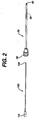
- Figure 1 shows a releasable and retrievable vascular filter system made in accordance with the present invention.
- the releasable and retrievable vascular filter system comprises a filter 10, having a proximal end 20, a distal end 30, and a plurality of struts 40 extending between them.
- the filter further comprises a porous filter membrane 50 attached to the filter distal end 30 and to the plurality of struts 40.
- the porous filter membrane 50 may have a length that is less than the length of the plurality of struts 40.
- the filter has a smaller first diameter for insertion into the lumen, and a larger second diameter, as illustrated in Figure 1 , for expanding to a diameter substantially equal to the diameter of the lumen and to be placed in a generally sealing relationship with the lumen.
- the filter further comprises an anti-migration feature, which causes the filter 10 to remain substantially stationary in the lumen.
- the anti-migration feature comprises the chronic outward force of the Nickel-Titanium material from which the filter may be made.
- the releasable and retrievable vascular filter system further comprises a deployment and release mechanism for causing the filter to be positioned in the lumen of the vessel and for causing the filter to achieve its second larger diameter.
- the deployment and release mechanism comprises a catheter 70, as shown in Figure 2 , with a proximal end 80, a distal end 90 and an inner lumen 95.
- the deployment and release mechanism further comprises an obdurator 100, having a proximal end 110 and a distal end 120, with the distal end 120 slidably insertable into the proximal end of the catheter 80.
- the releasable and retrievable vascular filter system further comprises a storage tube 65, having a proximal end 64 and a distal end 66.
- the distal end 30 of the filter 10, in the collapsed state may be slidably inserted into the proximal end 64 of the storage tube, and advanced until the storage tube 65 is coaxially disposed around the filter 10, as illustrated in Figure 3 . Then, the distal end of the storage tube 66 is slidably inserted into the proximal end of the catheter 80.
- the distal end 120 of the obdurator 100 may be slidably inserted into the proximal end 64 of the storage tube 65 and advanced until the distal end of the obdurator 120 is substantially in contact with the proximal end of the filter 20. The obdurator is then advanced further until the filter 10 is pushed into the proximal end of the catheter 80, through the catheter 70, as illustrated in Figure 4A , and then out of the distal end of the catheter 90, as illustrated in Figure 4B .
- the filter 10 then expands to achieve the second larger diameter, as illustrated in Figure 4B , and is positioned in the lumen, with the chronic outward force of the Nickel-Titanium alloy, from which the filter may be made, causing the filter 10 to remain stationary in the lumen.
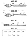
- the releasable and retrievable vascular filter system further comprises a retrieval device for recapturing the filter, for causing the filter to achieve the smaller first diameter, and for removing the filter from the lumen.
- the retrieval device comprises a ball hook retrieval system, as illustrated in Figure 5A .
- the ball hook retrieval system 130 comprises a wire 140 having a proximal end 150 and a distal end 160, with a curve 165 near the distal end of the wire 140, and a ball 170 attached near the distal end of the wire 160.
- the ball hook retrieval system further comprises a receiver 180 near the proximal end 20 of the filter 10, as illustrated in Figure 5B .
- the receiver 180 is accessed by inserting the ball 170 through the struts 40 of the filter 10, as illustrated in Figure 5C . Then, the wire 140 and the filter 10 are retracted back into the catheter 70. The filter 10 collapses, as illustrated in Figure 5D , and may then be withdrawn through the catheter 70.
- the releasable and retrievable vascular filter system may be used to introduce, deploy and release a vascular filter into the lumen of a vessel, and then to retrieve the vascular filter from the lumen of a vessel.
- the catheter 70 may be introduced into the lumen of a vessel, until the distal end of the catheter 90 is positioned past the location of an occlusion in the vessel. Then, the distal end 30 of the filter 10 is inserted into proximal end 64 of the storage tube 65, until the storage tube completely covers the filter, as illustrated in Figure 3 .
- the distal end of the storage tube 66 is inserted into the proximal end of the catheter 70, as illustrated in Figure 3 .
- the distal end 120 of the obdurator 100 is inserted into the proximal end of the storage tube 64 and advanced until it is substantially in contact with the proximal end of the filter 20.
- the obdurator 100 continues to be advanced until the filter 10 is pushed through the proximal end 80 of the catheter 70, through the catheter 70, and out of the distal end 90 of the catheter, as illustrated in Figure 4B .
- the filter 10 then achieves its second larger diameter, as illustrated in Figure 4B , and the anti-migration feature, in the form of the chronic outward force of the Nickel-Titanium alloy from which the filter is made, in this exemplary embodiment, allows the filter to remain substantially stationary in the lumen during the procedure.
- the filter captures embolic particulates generated during the procedure.
- the untethered filter 10 also allows the operator to perform guidewire exchanges, as needed throughout the procedure.
- the retrieval device in the form of the ball hook retrieval system 130 in this exemplary embodiment, is introduced through the catheter 70, as illustrated in Figure 5A .
- the ball 170 exits the distal end of the catheter 90, it is inserted through the filter struts 40, until it connects with the receiver 180, as illustrated in Figure 5C . Then, the wire 140 is retracted back through the catheter 70, causing the filter 10 to collapse once it enters the catheter 70. Then, the filter 10 may be withdrawn from the body, with the embolic particulates captures therein.
- the filter 10 may be made from any number of suitable materials, and is preferably made from Nickel-Titanium alloy.
- the filter 10 may comprise at least one marker band attached near the midpoints of the struts 40, at least one marker band attached near the distal end 30 of the filter, and at least one marker band attached near the proximal end 20 of the filter.
- the filter 10 may also comprise coatings or any other suitable means for enhancing the radiopacity of the device.
- the porous filter membrane 50 may be made from any number of suitable materials, and is preferably made from a flexible polymeric material with elastomeric properties chosen from a group consisting of polyurethane, polyethylene or a co-polymer thereof.
- the porous filter membrane 50 may comprise any number and configuration of pores and preferably comprises pores wherein the pore size is from about 20 to about 300 microns.
- the pores may be created by any suitable means, and may preferably be created by laser drilling.
- the storage tube 65 may be made from any number of suitable materials, and is preferably made from a polymeric material.
- the filter 10 may be loaded into the storage tube 65 at time of use, or may be preloaded, if the porous filter membrane 50 is made of a suitable material that does not take a permanent set.
- the catheter 70 may be made from any number of suitable materials, and is preferably made from a polymeric material.
- the obdurator 100 may be made from any number of suitable materials, and is preferably made from a polymeric material.
- the anti-migration device may comprise any number of suitable configurations, including hooks, barbs ( Figure 6A ), bowed features ( Figure 6B ), zig-zags ( Figure 6C ), dimples ( Figure 6D ), and square barbs ( Figure 6E ).
- the anti-migration feature may also comprise the chronic outward force of Nickel-Titanium alloy, from which the filter may be made, as illustrated in Figure 1 .
- the deployment and release mechanism may comprise any number of suitable configurations, as illustrated in Figures 4A and 4B , which comprises a catheter and obdurator deployment system described above, and as illustrated in Figures 7 and 8 .
- the catheter 70 is coaxially disposed around a shaft 200, with the filter 10 attached near the distal end of the shaft 200.
- the catheter 70 may be retracted, allowing the filter 10 to achieve the larger second diameter and to be placed in a generally sealing relationship with the lumen of the vessel, as illustrated in Figure 7B .
- the shaft 200 may be retracted to release the filter, as illustrated in Figure 7C .
- the catheter 70 is coaxially disposed around a sheath 215 and a guidewire 210, with the filter 10 attached near the distal end of the guidewire 210, via mating features 220 and 230, attached near the distal end of the guidewire 210, and near the proximal end of the filter 10.
- the catheter 70 may be retracted, allowing the filter 10 to achieve the larger second diameter and to be placed in a generally sealing relationship with the lumen of the vessel, as illustrated in Figure 8B .
- the mating features 220 and 230 are disengaged by retracting the sheath 215 to release the filter, as illustrated in Figure 8C .
- the mating features may be of any suitable configuration, and are preferably balls and holes, or mating slots, as illustrated in Figures 8D and 8E .
- the mating features may also release hydraulically, as illustrated in Figure 8E , where the sheath 215 exhibits the characteristic that when fluid pressure is applied to the inner diameter, via a syringe or other suitable means, the walls of the distal section of the sheath 217 expand outwardly and release the mating feature 230, and hence the filter 10.
- the shaft may be made from any number of suitable materials, and is preferably made from a metallic material at the distal end and a polymeric material at the proximal end.
- the sheath may be made from any suitable material, and is preferably made from a polymeric material.
- the wire may be made from any number of suitable materials, and is preferably made from Nickel-Titanium alloy.
- the snare may be made from any number of suitable materials, and is preferably made from Nickel-Titanium alloy.
- the retrieval device may comprise any number of suitable configurations, as illustrated in Figures 5A, 5B and 5C , which comprise the ball hook retrieval system, and Figures 8A, 8B, 8C and 8D , which comprise a mating hook system.
- the retrieval device may also comprise a snare 240 and a snareable feature 250 on the filter, as illustrated in Figure 9 .
- the snare 240 in introduced through a catheter, as illustrated in Figure 9 .
- the loop of the snare 250 exits the catheter and attaches itself to the snareable feature 250, on the filter 10, which is a hook in this exemplary embodiment.
- the snare 240 is then retracted back into the catheter 70, dragging the filter 10 into the catheter 70, and causing the filter to achieve its smaller first diameter, as illustrated in Figure 9C .
- the snareable feature may comprise any number of suitable configurations, as illustrated in Figure 9D , and may comprise hooks, knobs, slots or coils.
Abstract
Description
- This invention relates to the treatment of vascular disease, and more particularly to a vascular filter system for use during medical procedures.
- Percutaneous transluminal coronary angioplasty (PTCA), stenting and atherectomy are therapeutic medical procedures used to increase blood flow through the coronary arteries. These procedures may often be performed as alternatives to coronary bypass surgery. Percutaneous transluminal angioplasty (PTA) and stenting may often be performed as alternatives to carotid endarterectomy, and femoral-popliteal bypass procedures. In PTCA or PTA procedures, the angioplasty balloon is inflated within the stenosed vessel, at the location of an occlusion, in order to shear and disrupt the wall components of the vessel to obtain an enlarged lumen. In stenting, an endoluminal prosthesis is implanted in the vessel to maintain patency following the procedure. In atherectomy, a rotating blade is used to shear plaque from the arterial wall.
- One of the complications associated with all these techniques is the accidental dislodgment of plaque, thrombus or other embolic particulates generated during manipulation of the vessel, thereby potentially causing occlusion of the narrower vessels downstream, which may lead to ischemia or infarct of the organ which the vessel supplies. Such emboli may be extremely dangerous to the patient, and may result in myocardial infarction, stroke or limb ischemia. In 1995, Waksman et al. disclosed that distal embolization is common after directional atherectomy in coronary arteries and saphenous vein grafts. See Waksman et al., American Heart Journal 129(3): 430-5 (1995). This study found that distal embolization occurs in 28 percent (31 out of 111) of the patients undergoing atherectomy. In January 1999, Jordan, Jr. et al. disclosed that treatment of carotid stenosis using percutaneous angioplasty with stenting procedure is associated with more than eight times the rate of microemboli seen using carotid endarterectomy. See Jordan, Jr. et al. Cardiovascular Surgery 7(1): 33-8 (1999). Microemboli, as detected by transcranial Doppler monitoring in this study, have been shown to be a potential cause of stroke. The embolic materials include calcium, intimal debris, atheromatous plaque, and thrombi.
- Vascular filters are also well known in the art, especially vena cava filters, as illustrated in
US-4727873 andUS-4688553 . There is also a substantial amount of medical literature describing various designs of vascular filters and reporting the results of clinical and experimental use thereof. See, for example, the article by Eichelter and Schenk, entitled "Prophylaxis of Pulmonary Embolism," Archives of Surgery, Vol. 97 (August, 1968). See, also, the article by Greenfield, et al; entitled "A New Intracaval Filter Permitting Continued Flow and Resolution of Emboli," Surgery, Vol. 73, No. 4 (1973). - Vascular filters are often used during a postoperative period, when there is a perceived risk of a patient encountering pulmonary embolism resulting from clots generated peri-operatively. Pulmonary embolism is a serious and potentially fatal condition that occurs when these clots travel to the lungs. The filter is therefore typically placed in the vena cava to catch and trap clots before they can reach the lungs.
- Many of the vascular filters in the prior art are intended to be permanently placed in the venous system of the patient, so that even after the need for the filter has passed, the filter remains in place for the life of the patient.
US-3952747 discloses a stainless steel filtering device that is permanently implanted transvenously within the inferior vena cava. This device is intended to treat recurrent pulmonary embolism. Permanent implantation is often deemed medically undesirable, but it is done because filters are implanted in patients in response to potentially life-threatening situations. - To avoid permanent implantation, it is highly desirable to provide an apparatus and method for preventing embolization associated with angioplasty, stenting or other procedures. In particular, it is desirable to provide a device that may be temporarily placed within the vascular system to collect and retrieve plaque, thrombus and other embolic particulates that have been dislodged during angioplasty, stenting or other procedures. Such a device is removed at the end of the procedure.
US-6179861 andUS-6001118 describe guidewire-based filters where the filter resembles a windsock and is supported by one or more articulated support hoops.US-5814064 andUS-5827324 describe guidewire-based filter devices, wherein the filter is expanded to a predetermined diameter through the introduction of a fluid or a gas.US-6168604 andUS-6152946 describe guidewire-based filters, wherein the diameter of the filter is controlled by advancing and retracting a sheath over the filter component. - Notwithstanding the usefulness of the above-described methods, one concern commonly encountered with these devices is that the filter may move when the guidewire moves, thereby causing potential damage to the lumen, and risking the release of embolic particulates had been captured during the procedure. Another concern commonly encountered with these devices is that the filter and the guidewire are a single unit. Therefore, guidewire exchanges, which may be necessary for successful completion of the clinical procedure, cannot be performed.
- The prior art has yet to disclose, and a need still exists for, a vascular filter system which may be used to address the clinical problem of minimizing or substantially eliminating movement of the filter during the clinical procedure. The prior art has also not yet disclosed, and a need still exists for, a vascular filter which may be used to address the problem of allowing guidewires exchanges, which may be necessary for successful completion of the clinical procedure.
-
WO-A-01/45592 - The present invention provides a releasable and retrievable vascular filter system, which may be used to address the clinical problems of minimizing or substantially eliminating movement of the filter during the clinical procedure, and allowing guidewire exchanges, which may be necessary for successful completion of the clinical procedure, as briefly described above.
- An objective of the invention is to provide a releasable and retrievable vascular filter system which places an untethered filter into the lumen of the vessel, in a position distal to the occlusion or to the location of the necessary intervention, which will remain stationary during the procedure. The filter system comprises a filter with an anti-migration feature, a deployment and release mechanism, and a retrieval device. The filter deployment and release mechanism allows for proper filter placement within the lumen. The deployment mechanism also allows the filter to expand to its second larger diameter, which is substantially equal to the diameter of the lumen, and to be placed in a generally sealing relationship with the lumen. The anti-migration feature allows the filter to remain substantially stationary in the lumen of a vessel during the procedure. The filter is untethered by a guidewire, and therefore does not move when the guidewire moves. The filter remains in place, capturing embolic particulates that may be released during the procedure. Another objective of the invention is to allow guidewire exchanges to be performed throughout the procedure, as needed, without disturbing or moving the filter. Then, a retrieval device is utilized for recapturing, collapsing and removing the filter from the lumen, with the embolic particulates captured within the filter.
- In accordance with one aspect, the present invention is directed to a releasable and retrievable vascular filter system as defined in appended claim 1 for insertion into a lumen of a vessel, comprising a vascular filter with a smaller first diameter for insertion into the lumen and a larger second diameter for expanding to a diameter substantially equal to the diameter of the lumen and to be placed in a generally sealing relationship with the lumen. The system further comprises a porous filter membrane attached to the filter, a deployment and release mechanism for causing the filter to be positioned in the lumen of the vessel and to achieve the second larger diameter, an anti-migration feature for causing the filter to remain stationary in the lumen, and a retrieval device for recapturing the filter, for causing the filter to achieve the smaller first diameter, and for removing the filter from the lumen.
- In one embodiment, the deployment and release mechanism may comprise a storage tube having a proximal end, a distal end, and an inner lumen, with the distal end of the filter slidably insertable into the proximal end of the storage tube. The deployment and release mechanism further comprises a catheter having a proximal end, a distal end, and an inner lumen, with the distal end of the storage tube containing the filter slidably insertable into the proximal end of the catheter. The deployment and release mechanism further comprises an obdurator having an outer diameter, a proximal end and a distal end, with the distal end of the obdurator slidably insertable into the proximal end of the storage tube until the distal end of the obdurator is substantially in contact with the proximal end of the filter, and the obdurator is positioned to push the filter into the proximal end of the catheter, through the lumen of the catheter, and out of the distal end of the catheter.
- In another embodiment, the deployment and release mechanism may comprise a catheter having a proximal end, a distal end, and an inner lumen. The deployment and release mechanism further comprises a shaft having an outer diameter, a proximal end and a distal end, with the filter releasably attached near the distal end of the shaft, and the catheter coaxially disposed around the shaft and the filter, such that the catheter may be slidably retracted to deploy the filter.
- In another embodiment, the deployment and release mechanism may comprise a guidewire, with the proximal end of the filter releasably attachable near and detachable from the distal end of the guidewire. The deployment and release mechanism further comprises a catheter having a proximal end, a distal end, and an inner lumen, with the proximal end of the guidewire slidaby insertable into the distal end of the catheter until the catheter is coaxially disposed around the guidewire and the filter, and the catheter may be slidably retracted to deploy the filter.
- The anti-migration feature may comprise the chronic outward force of Nickel-Titanium alloy.
- The anti-migration feature may comprise hooks attached to the filter.
- The anti-migration feature may comprise the frictional force of the geometric design of the struts.
- The anti-migration feature may comprise a friction coating on the filter.
- The anti-migration feature may comprise a surface treatment that increases the friction coefficient of the filter.
- The retrieval device may comprise a snare, and the filter comprises a snareable feature.
- The retrieval device may comprise a wire having an outer diameter, a proximal end and a distal end, a hook attached near the distal end of the wire, and a hook attached near the proximal end of the filter.
- The retrieval device may comprise a wire having an outer diameter, a proximal end and a distal end, a ball attached near the distal end of the wire, and a receiver attached near the proximal end of the filter.
- The retrieval device may comprise a guidewire detachable from and attachable to the filter.
- The releasable and retrievable vascular filter system of the present invention is designed to address the clinical problem of movement of the filter when the guidewire moves, thereby causing potential damage to the lumen, and risking the release of embolic particulates which were captured during the procedure. The releasable and retrievable vascular filter system of the present invention is also designed to address the need to exchange guidewires, which may be necessary for successful completion of the clinical procedure. Guidewire exchanges may be necessary because different guidewire characteristics may be needed during different portions of the clinical procedure. For example, guidewire torqueability and steerability may be required at the beginning of the procedure, in order to access the site of the occlusion or necessary intervention. Then, extra support may be required later in the procedure, when the guidewire is needed to serve as a conduit for other procedural devices.
- The releasable and retrievable vascular filter system comprises a vascular filter with a smaller first diameter for insertion into the lumen and a larger second diameter for expanding to a diameter substantially equal to the diameter of the lumen and to be placed in a generally sealing relationship with the lumen. The system further comprises a porous filter membrane attached to the filter, a deployment and release mechanism for causing the filter to be positioned in the lumen of the vessel and to achieve the second larger diameter, an anti-migration feature for causing the filter to remain stationary in the lumen, and a retrieval device for recapturing the filter, for causing the filter to achieve the smaller first diameter, and for removing the filter from the lumen. The deployment and release mechanism is utilized to place the filter in the lumen of the vessel, in a position distal to the occlusion or to the location of the necessary intervention. The deployment and release mechanism also allows the filter to expand to its second larger diameter, which substantially equals the diameter of the lumen, and to be placed in a generally sealing relationship with the lumen. The anti-migration feature allows the filter to remain substantially stationary in the lumen of a vessel during the procedure. The filter is untethered by a guidewire, and therefore does not move when the guidewire moves. The filter remains in place, capturing embolic particulates which may be released during the procedure. Then, a retrieval device is utilized for recapturing, collapsing and removing the filter from the lumen, with the embolic particulates captured within the filter.
- An advantage of the present invention is that the anti-migration feature of the filter causes it to remain stationary in the lumen during the procedure, thereby minimizing the risk of potential damage to the lumen, and minimizing the risk of releasing embolic particulates which had been captured during the procedure. Another advantage of the present invention is that the filter and the guidewire are not a single unit, so the operator may freely exchange guidewires, which may be necessary for successful completion of the clinical procedure.
- Embodiments of the invention will now be described by way of example with reference to the accompanying drawings, in which:
-
Figure 1 illustrates a partial, enlarged cross-sectional view of an exemplary embodiment of the releasable and retrievable vascular filter system, with the filter in the expanded position and the anti-migration feature comprising the chronic outward force of the Nickel-Titanium alloy, in accordance with the present invention. -
Figure 2 illustrates a partial, cross-sectional view of an exemplary embodiment of the releasable and retrievable vascular filter system, with the deployment and release mechanism comprising a catheter and obdurator, in accordance with the present invention, -
Figure 3 illustrates a partial, cross-sectional view of an exemplary embodiment of the releasable and retrievable vascular filter system, with the storage tube and filter being inserted into the catheter, in accordance with the present invention. -
Figures 4A and Figure 4B illustrate partial, cross-sectional views of an exemplary embodiment of the releasable and retrievable vascular filter system, with the obdurator pushing the filter out of the catheter, in accordance with the present invention. -
Figures 5A, 5B, 5C and 5D illustrate partial, enlarged, cross-sectional views of an exemplary embodiment of the releasable and retrievable vascular filter system, using a ball hook retrieval system, in accordance with the present invention. -
Figure 6 illustrates a partial, simplified, top and sides view of exemplary embodiments of the releasable and retrievable vascular filter system, with suitable configurations of the anti-migration feature, in accordance with the present invention. -
Figures 7A, 7B and 7C illustrate partial, enlarged, cross-sectional views of an exemplary embodiment of the releasable and retrievable vascular filter system, with the catheter being retracted to deploy the filter, in accordance with the present invention. -
Figures 8A, 8B and 8C illustrate partial, enlarged, cross-sectional views of an exemplary embodiment of the releasable and retrievable vascular filter system, with the catheter being retracted and the guidewire disengaged, to deploy the filter, in accordance with the present invention.Figures 8D, 8E and 8F are partial, enlarged, cross-sectional views of exemplary embodiments of the mating features on the guidewire and filter, in accordance with the present invention. -
Figures 9A, 9B and 9C illustrate partial, enlarged, cross-sectional views of an exemplary embodiment of the releasable and retrievable vascular filter system, with a snare being used to retrieve the filter, in accordance with the present invention.Figure 9D illustrates a partial, enlarged, cross-sectional view of exemplary embodiments of the snareable feature on the filter, in accordance with the present invention. - Referring to the figures wherein like numerals indicate the same element throughout the views,
Figure 1 shows a releasable and retrievable vascular filter system made in accordance with the present invention. The releasable and retrievable vascular filter system comprises afilter 10, having aproximal end 20, adistal end 30, and a plurality ofstruts 40 extending between them. The filter further comprises aporous filter membrane 50 attached to the filterdistal end 30 and to the plurality ofstruts 40. Theporous filter membrane 50 may have a length that is less than the length of the plurality ofstruts 40. The filter has a smaller first diameter for insertion into the lumen, and a larger second diameter, as illustrated inFigure 1 , for expanding to a diameter substantially equal to the diameter of the lumen and to be placed in a generally sealing relationship with the lumen. The filter further comprises an anti-migration feature, which causes thefilter 10 to remain substantially stationary in the lumen. In this exemplary embodiment, the anti-migration feature comprises the chronic outward force of the Nickel-Titanium material from which the filter may be made. - The releasable and retrievable vascular filter system further comprises a deployment and release mechanism for causing the filter to be positioned in the lumen of the vessel and for causing the filter to achieve its second larger diameter. In this exemplary embodiment, the deployment and release mechanism comprises a
catheter 70, as shown inFigure 2 , with aproximal end 80, adistal end 90 and aninner lumen 95. The deployment and release mechanism further comprises anobdurator 100, having aproximal end 110 and adistal end 120, with thedistal end 120 slidably insertable into the proximal end of thecatheter 80. As illustrated inFigure 3 , the releasable and retrievable vascular filter system further comprises astorage tube 65, having aproximal end 64 and adistal end 66. Thedistal end 30 of thefilter 10, in the collapsed state, may be slidably inserted into theproximal end 64 of the storage tube, and advanced until thestorage tube 65 is coaxially disposed around thefilter 10, as illustrated inFigure 3 . Then, the distal end of thestorage tube 66 is slidably inserted into the proximal end of thecatheter 80. At this point, as illustrated inFigure 4 , thedistal end 120 of theobdurator 100 may be slidably inserted into theproximal end 64 of thestorage tube 65 and advanced until the distal end of theobdurator 120 is substantially in contact with the proximal end of thefilter 20. The obdurator is then advanced further until thefilter 10 is pushed into the proximal end of thecatheter 80, through thecatheter 70, as illustrated inFigure 4A , and then out of the distal end of thecatheter 90, as illustrated inFigure 4B . Thefilter 10 then expands to achieve the second larger diameter, as illustrated inFigure 4B , and is positioned in the lumen, with the chronic outward force of the Nickel-Titanium alloy, from which the filter may be made, causing thefilter 10 to remain stationary in the lumen. - The releasable and retrievable vascular filter system further comprises a retrieval device for recapturing the filter, for causing the filter to achieve the smaller first diameter, and for removing the filter from the lumen. In this exemplary embodiment, the retrieval device comprises a ball hook retrieval system, as illustrated in
Figure 5A . The ballhook retrieval system 130 comprises awire 140 having aproximal end 150 and adistal end 160, with acurve 165 near the distal end of thewire 140, and aball 170 attached near the distal end of thewire 160. The ball hook retrieval system further comprises areceiver 180 near theproximal end 20 of thefilter 10, as illustrated inFigure 5B . Thereceiver 180 is accessed by inserting theball 170 through thestruts 40 of thefilter 10, as illustrated inFigure 5C . Then, thewire 140 and thefilter 10 are retracted back into thecatheter 70. Thefilter 10 collapses, as illustrated inFigure 5D , and may then be withdrawn through thecatheter 70. - As illustrated in
Figure 1 ,2 ,3 ,4A ,4B ,5A, 5B, 5C and 5D , the releasable and retrievable vascular filter system may be used to introduce, deploy and release a vascular filter into the lumen of a vessel, and then to retrieve the vascular filter from the lumen of a vessel. Thecatheter 70 may be introduced into the lumen of a vessel, until the distal end of thecatheter 90 is positioned past the location of an occlusion in the vessel. Then, thedistal end 30 of thefilter 10 is inserted intoproximal end 64 of thestorage tube 65, until the storage tube completely covers the filter, as illustrated inFigure 3 . At this point, the distal end of thestorage tube 66 is inserted into the proximal end of thecatheter 70, as illustrated inFigure 3 . Then, thedistal end 120 of theobdurator 100 is inserted into the proximal end of thestorage tube 64 and advanced until it is substantially in contact with the proximal end of thefilter 20. Theobdurator 100 continues to be advanced until thefilter 10 is pushed through theproximal end 80 of thecatheter 70, through thecatheter 70, and out of thedistal end 90 of the catheter, as illustrated inFigure 4B . Thefilter 10 then achieves its second larger diameter, as illustrated inFigure 4B , and the anti-migration feature, in the form of the chronic outward force of the Nickel-Titanium alloy from which the filter is made, in this exemplary embodiment, allows the filter to remain substantially stationary in the lumen during the procedure. The filter captures embolic particulates generated during the procedure. Theuntethered filter 10 also allows the operator to perform guidewire exchanges, as needed throughout the procedure. After the interventional procedure is complete, the retrieval device, in the form of the ballhook retrieval system 130 in this exemplary embodiment, is introduced through thecatheter 70, as illustrated inFigure 5A . Once theball 170 exits the distal end of thecatheter 90, it is inserted through the filter struts 40, until it connects with thereceiver 180, as illustrated inFigure 5C . Then, thewire 140 is retracted back through thecatheter 70, causing thefilter 10 to collapse once it enters thecatheter 70. Then, thefilter 10 may be withdrawn from the body, with the embolic particulates captures therein. - The
filter 10 may be made from any number of suitable materials, and is preferably made from Nickel-Titanium alloy. Thefilter 10 may comprise at least one marker band attached near the midpoints of thestruts 40, at least one marker band attached near thedistal end 30 of the filter, and at least one marker band attached near theproximal end 20 of the filter. Thefilter 10 may also comprise coatings or any other suitable means for enhancing the radiopacity of the device. Theporous filter membrane 50 may be made from any number of suitable materials, and is preferably made from a flexible polymeric material with elastomeric properties chosen from a group consisting of polyurethane, polyethylene or a co-polymer thereof. Theporous filter membrane 50 may comprise any number and configuration of pores and preferably comprises pores wherein the pore size is from about 20 to about 300 microns. The pores may be created by any suitable means, and may preferably be created by laser drilling. Thestorage tube 65 may be made from any number of suitable materials, and is preferably made from a polymeric material. Thefilter 10 may be loaded into thestorage tube 65 at time of use, or may be preloaded, if theporous filter membrane 50 is made of a suitable material that does not take a permanent set. Thecatheter 70 may be made from any number of suitable materials, and is preferably made from a polymeric material. Theobdurator 100 may be made from any number of suitable materials, and is preferably made from a polymeric material. - The anti-migration device may comprise any number of suitable configurations, including hooks, barbs (
Figure 6A ), bowed features (Figure 6B ), zig-zags (Figure 6C ), dimples (Figure 6D ), and square barbs (Figure 6E ). The anti-migration feature may also comprise the chronic outward force of Nickel-Titanium alloy, from which the filter may be made, as illustrated inFigure 1 . - The deployment and release mechanism may comprise any number of suitable configurations, as illustrated in
Figures 4A and 4B , which comprises a catheter and obdurator deployment system described above, and as illustrated inFigures 7 and8 . InFigure 7A , thecatheter 70 is coaxially disposed around ashaft 200, with thefilter 10 attached near the distal end of theshaft 200. When the system is in position distal to the occlusion in the lumen of the vessel, thecatheter 70, may be retracted, allowing thefilter 10 to achieve the larger second diameter and to be placed in a generally sealing relationship with the lumen of the vessel, as illustrated inFigure 7B . Then, theshaft 200 may be retracted to release the filter, as illustrated inFigure 7C . InFigure 8A , thecatheter 70 is coaxially disposed around asheath 215 and aguidewire 210, with thefilter 10 attached near the distal end of theguidewire 210, via mating features 220 and 230, attached near the distal end of theguidewire 210, and near the proximal end of thefilter 10. When the system is in position distal to the occlusion in the lumen of the vessel, thecatheter 70 may be retracted, allowing thefilter 10 to achieve the larger second diameter and to be placed in a generally sealing relationship with the lumen of the vessel, as illustrated inFigure 8B . Then, the mating features 220 and 230 are disengaged by retracting thesheath 215 to release the filter, as illustrated inFigure 8C . The mating features may be of any suitable configuration, and are preferably balls and holes, or mating slots, as illustrated inFigures 8D and 8E . The mating features may also release hydraulically, as illustrated inFigure 8E , where thesheath 215 exhibits the characteristic that when fluid pressure is applied to the inner diameter, via a syringe or other suitable means, the walls of the distal section of thesheath 217 expand outwardly and release themating feature 230, and hence thefilter 10. The shaft may be made from any number of suitable materials, and is preferably made from a metallic material at the distal end and a polymeric material at the proximal end. The sheath may be made from any suitable material, and is preferably made from a polymeric material. The wire may be made from any number of suitable materials, and is preferably made from Nickel-Titanium alloy. The snare may be made from any number of suitable materials, and is preferably made from Nickel-Titanium alloy. - The retrieval device may comprise any number of suitable configurations, as illustrated in
Figures 5A, 5B and 5C , which comprise the ball hook retrieval system, andFigures 8A, 8B, 8C and 8D , which comprise a mating hook system. The retrieval device may also comprise asnare 240 and asnareable feature 250 on the filter, as illustrated inFigure 9 . Thesnare 240 in introduced through a catheter, as illustrated inFigure 9 . The loop of thesnare 250 exits the catheter and attaches itself to the snareable feature 250, on thefilter 10, which is a hook in this exemplary embodiment. Thesnare 240 is then retracted back into thecatheter 70, dragging thefilter 10 into thecatheter 70, and causing the filter to achieve its smaller first diameter, as illustrated inFigure 9C . The snareable feature may comprise any number of suitable configurations, as illustrated inFigure 9D , and may comprise hooks, knobs, slots or coils.
Claims (27)
- A vascular filter system for insertion into a lumen of a vessel, said system comprising:a) a filter support structure comprising a proximal portion (20), a distal portion (30), and a plurality of struts (40) extending between them, said struts (40) further comprising proximal portions and distal portions, said filter having a smaller first diameter for insertion into said lumen, and a second larger diameter for expanding to a diameter substantially equal to the diameter of said lumen and to be placed in a generally sealing relationship with said lumen; andb) a porous filter membrane (50) connected to said filter distal portion (30) and said plurality of struts (40); characterised byc) deploying and releasing means operatively associated with said filter support structure, said deploying and releasing means causing said filter to be positioned in said lumen of said vessel, and causing said filter to achieve said larger second diameter;d) anti-migration means associated with said filter support structure, said anti-migration means causing said filter to remain substantially stationary in said lumen of said vessel; ande) retrieving means operatively associated with said filter support structure, said retrieving means allowing recapture of said filter, causing said filter to achieve said smaller first diameter, and allowing removal of said filter from said lumen.
- The vascular filter system according to claim 1, wherein said filter support structure is made from Nickel-Titanium alloy.
- The vascular filter system according to claim 2, wherein said anti-migration means comprises the chronic outward force of said Nickel-Titanium alloy.
- The vascular filter system according to claim 1, wherein said filter support structure further comprises means to enhance the radiopacity of the device.
- The vascular filter system according to claim 1, wherein said porous filter membrane is made from a polymeric material chosen from a group consisting of polyurethane, polyethylene or a co-polymer thereof.
- The vascular filter system according to claim 5, wherein the pore size of said porous filter membrane (50) is in the range of from about 20 to about 300 microns.
- The vascular filter system according to claim 1, wherein said deploying means comprises a storage tube (65) having an proximal end (64) and a distal end (66) and an inner lumen, with said distal end of said filter slidably insertable into said proximal end (64) of said storage tube (65); said deploying means further comprising a catheter (70) having an outer diameter and an inner diameter, a proximal end (80) and a distal end (90), and an inner lumen (95), with said distal end (66) of storage tube (65) containing said filter slidably insertable into said proximal end (80) of said catheter (70); said deploying means further comprising an obdurator (100) having an outer diameter, a proximal end (110) and a distal end (120), with said distal end (120) of said obdurator (100) slidably insertable into said proximal end (64) of said storage tube (65) until said distal end (120) of said obdurator (100) is substantially in contact with said proximal end of said filter, and said obdurator (100) is positioned to push said filter into said proximal end (80) of said catheter (70), through said lumen (95) of said catheter (70), and out of said distal end (90) of said catheter (70).
- The vascular filter system according to claim 7, wherein said storage tube (65) is made from a polymeric material.
- The vascular filter system according to claim 7, wherein said catheter (70) is made from a polymeric material.
- The vascular filter system according to claim 7, wherein said obdurator (100) is made from a polymeric material.
- The vascular filter system according to claim 1, wherein said deploying means comprises a catheter (70) having an outer diameter and an inner diameter, a proximal end and a distal end, and an inner lumen, said deploying means further comprising a shaft (200) having an outer diameter, a proximal end and a distal end, with said filter releasably attached near and detachable from said distal end of said shaft (200), and said catheter (70) coaxially disposed around said shaft (200) and said filter, such that said catheter (70) may be slidably retracted to deploy said filter.
- The vascular filter system according to claim 11, wherein said catheter (70) is made from a polymeric material.
- The vascular filter system according to claim 11, wherein said distal end of said shaft (200) is made from a metallic material and said proximal end of said shaft is made from a polymeric material.
- The vascular filter system according to claim 1, wherein said deploying means comprises a guidewire (210) having a proximal end and a distal end, with said proximal end of said filter releasably attachable near and detachable from said distal end of said guidewire (210); said deploying means further comprising a catheter (70) having an outer diameter and an inner diameter, a proximal end and a distal end, and an inner lumen, with said proximal end of said guidewire (210) slidaby insertable into said distal end of said catheter (70) until said catheter (70) is coaxially disposed around said guidewire (210) and said filter, and said catheter (70) may be slidably retracted to deploy said filter.
- The vascular filter system according to claim 14, wherein said guidewire (210) is made from Nickel-Titanium alloy.
- The vascular filter system according to claim 14, wherein said catheter (70) is made from a polymeric material.
- The vascular filter system according to claim 1, wherein said anti-migration means comprises hooks attached to said struts (40).
- The vascular filter system according to claim 1, wherein said anti-migration means comprises the frictional force of a geometric design of said struts (40).
- The vascular filter system according to claim 1, wherein said anti-migration means comprises a friction coating on said filter support structure.
- The vascular filter system according to claim 1, wherein said anti-migration means comprises a surface treatment on said filter support structure.
- The vascular filter system according to claim 1, wherein said retrieving means comprises a snare (240), and a snareable feature (250) on said proximal end of said filter.
- The vascular filter system according to claim 21, wherein said snare (240) is made from Nickel-Titanium alloy.
- The vascular filter system according to claim 1, wherein said retrieving means comprises a guidewire (210) having an outer diameter, a proximal end and a distal end, said retrieving means further comprising a hook attached near said distal end of said guidewire and a hook attached near said proximal end of said filter.
- The vascular filter system according to claim 23, wherein said hooks have c-shaped configurations.
- The vascular filter system according to claim 23, wherein said hooks have t-shaped configurations.
- The vascular filter system according to claim 1, wherein said retrieving means comprises a wire (140) having an outer diameter, a proximal end (150) and a distal end (160), said retrieving means further comprising a ball (170) attached near said distal end (160) of said wire (140) and a receiver (180) attached near said proximal portion of said filter.
- The vascular filter system according to claim 1, wherein said retrieving means comprises a guidewire (210) detachable from and attachable to said filter.
Applications Claiming Priority (2)
| Application Number | Priority Date | Filing Date | Title |
|---|---|---|---|
| US40817 | 1998-03-18 | ||
| US10/040,817 US6958074B2 (en) | 2002-01-07 | 2002-01-07 | Releasable and retrievable vascular filter system |
Publications (2)
| Publication Number | Publication Date |
|---|---|
| EP1346703A1 EP1346703A1 (en) | 2003-09-24 |
| EP1346703B1 true EP1346703B1 (en) | 2009-12-16 |
Family
ID=21913126
Family Applications (1)
| Application Number | Title | Priority Date | Filing Date |
|---|---|---|---|
| EP03250037A Expired - Lifetime EP1346703B1 (en) | 2002-01-07 | 2003-01-06 | Releasable and retrievable vascular filter system |
Country Status (8)
| Country | Link |
|---|---|
| US (1) | US6958074B2 (en) |
| EP (1) | EP1346703B1 (en) |
| JP (1) | JP4417011B2 (en) |
| AT (1) | ATE451889T1 (en) |
| AU (1) | AU2002320662B2 (en) |
| CA (1) | CA2415978C (en) |
| DE (1) | DE60330519D1 (en) |
| MX (1) | MXPA03000143A (en) |
Families Citing this family (156)
| Publication number | Priority date | Publication date | Assignee | Title |
|---|---|---|---|---|
| US7491216B2 (en) | 1997-11-07 | 2009-02-17 | Salviac Limited | Filter element with retractable guidewire tip |
| US6336934B1 (en) | 1997-11-07 | 2002-01-08 | Salviac Limited | Embolic protection device |
| US7314477B1 (en) | 1998-09-25 | 2008-01-01 | C.R. Bard Inc. | Removable embolus blood clot filter and filter delivery unit |
| US6964672B2 (en) | 1999-05-07 | 2005-11-15 | Salviac Limited | Support frame for an embolic protection device |
| US6918921B2 (en) | 1999-05-07 | 2005-07-19 | Salviac Limited | Support frame for an embolic protection device |
| US6575997B1 (en) | 1999-12-23 | 2003-06-10 | Endovascular Technologies, Inc. | Embolic basket |
| US6660021B1 (en) | 1999-12-23 | 2003-12-09 | Advanced Cardiovascular Systems, Inc. | Intravascular device and system |
| US6402771B1 (en) | 1999-12-23 | 2002-06-11 | Guidant Endovascular Solutions | Snare |
| US7918820B2 (en) | 1999-12-30 | 2011-04-05 | Advanced Cardiovascular Systems, Inc. | Device for, and method of, blocking emboli in vessels such as blood arteries |
| US6695813B1 (en) | 1999-12-30 | 2004-02-24 | Advanced Cardiovascular Systems, Inc. | Embolic protection devices |
| GB2369575A (en) | 2000-04-20 | 2002-06-05 | Salviac Ltd | An embolic protection system |
| US6964670B1 (en) | 2000-07-13 | 2005-11-15 | Advanced Cardiovascular Systems, Inc. | Embolic protection guide wire |
| US6506203B1 (en) | 2000-12-19 | 2003-01-14 | Advanced Cardiovascular Systems, Inc. | Low profile sheathless embolic protection system |
| US8282668B2 (en) | 2001-06-18 | 2012-10-09 | Rex Medical, L.P. | Vein filter |
| US6599307B1 (en) | 2001-06-29 | 2003-07-29 | Advanced Cardiovascular Systems, Inc. | Filter device for embolic protection systems |
| US7338510B2 (en) | 2001-06-29 | 2008-03-04 | Advanced Cardiovascular Systems, Inc. | Variable thickness embolic filtering devices and method of manufacturing the same |
| US6951570B2 (en) * | 2001-07-02 | 2005-10-04 | Rubicon Medical, Inc. | Methods, systems, and devices for deploying a filter from a filter device |
| US6638294B1 (en) | 2001-08-30 | 2003-10-28 | Advanced Cardiovascular Systems, Inc. | Self furling umbrella frame for carotid filter |
| US6592606B2 (en) | 2001-08-31 | 2003-07-15 | Advanced Cardiovascular Systems, Inc. | Hinged short cage for an embolic protection device |
| US8262689B2 (en) | 2001-09-28 | 2012-09-11 | Advanced Cardiovascular Systems, Inc. | Embolic filtering devices |
| US7241304B2 (en) | 2001-12-21 | 2007-07-10 | Advanced Cardiovascular Systems, Inc. | Flexible and conformable embolic filtering devices |
| EP1455681B1 (en) | 2001-12-21 | 2014-09-17 | Salviac Limited | A support frame for an embolic protection device |
| US9204956B2 (en) | 2002-02-20 | 2015-12-08 | C. R. Bard, Inc. | IVC filter with translating hooks |
| US8177790B2 (en) * | 2002-04-20 | 2012-05-15 | Friedhelm Brassel | Medical retriever |
| US7252675B2 (en) | 2002-09-30 | 2007-08-07 | Advanced Cardiovascular, Inc. | Embolic filtering devices |
| US7331973B2 (en) | 2002-09-30 | 2008-02-19 | Avdanced Cardiovascular Systems, Inc. | Guide wire with embolic filtering attachment |
| US6989021B2 (en) * | 2002-10-31 | 2006-01-24 | Cordis Corporation | Retrievable medical filter |
| US20040088000A1 (en) | 2002-10-31 | 2004-05-06 | Muller Paul F. | Single-wire expandable cages for embolic filtering devices |
| US8252019B2 (en) * | 2003-01-31 | 2012-08-28 | Cordis Corporation | Filter retrieval catheter system, and methods |
| JP4382086B2 (en) * | 2003-01-31 | 2009-12-09 | コーディス・コーポレイション | Filter collection catheter system and filter collection method |
| US8591540B2 (en) | 2003-02-27 | 2013-11-26 | Abbott Cardiovascular Systems Inc. | Embolic filtering devices |
| EP1617766B1 (en) * | 2003-04-22 | 2015-08-05 | Patrick Leahy | A device for use in parietal surgery |
| US7892251B1 (en) | 2003-11-12 | 2011-02-22 | Advanced Cardiovascular Systems, Inc. | Component for delivering and locking a medical device to a guide wire |
| US7338512B2 (en) * | 2004-01-22 | 2008-03-04 | Rex Medical, L.P. | Vein filter |
| US8211140B2 (en) * | 2004-01-22 | 2012-07-03 | Rex Medical, L.P. | Vein filter |
| US8500774B2 (en) | 2004-01-22 | 2013-08-06 | Rex Medical, L.P. | Vein filter |
| US7704266B2 (en) | 2004-01-22 | 2010-04-27 | Rex Medical, L.P. | Vein filter |
| US8062326B2 (en) | 2004-01-22 | 2011-11-22 | Rex Medical, L.P. | Vein filter |
| US7976562B2 (en) | 2004-01-22 | 2011-07-12 | Rex Medical, L.P. | Method of removing a vein filter |
| US9510929B2 (en) | 2004-01-22 | 2016-12-06 | Argon Medical Devices, Inc. | Vein filter |
| US8162972B2 (en) | 2004-01-22 | 2012-04-24 | Rex Medical, Lp | Vein filter |
| US20110208233A1 (en) * | 2004-01-22 | 2011-08-25 | Mcguckin Jr James F | Device for preventing clot migration from left atrial appendage |
| US7678129B1 (en) | 2004-03-19 | 2010-03-16 | Advanced Cardiovascular Systems, Inc. | Locking component for an embolic filter assembly |
| US8353926B2 (en) * | 2004-04-15 | 2013-01-15 | Cordis Corporation | Long-term retrievable medical filter |
| AU2005267848A1 (en) * | 2004-07-30 | 2006-02-09 | Pacific Title & Arts Studio, Inc. | Method for conversion and reproduction of film images through a digital process |
| US7704267B2 (en) | 2004-08-04 | 2010-04-27 | C. R. Bard, Inc. | Non-entangling vena cava filter |
| ATE520369T1 (en) * | 2004-09-17 | 2011-09-15 | Nitinol Dev Corp | SHAPE MEMORY THIN FILM EMBOLIC PROTECTION DEVICE |
| EP1811919B1 (en) | 2004-09-27 | 2015-05-20 | Rex Medical, L.P. | Vein filter |
| US8795315B2 (en) | 2004-10-06 | 2014-08-05 | Cook Medical Technologies Llc | Emboli capturing device having a coil and method for capturing emboli |
| WO2006052894A1 (en) * | 2004-11-08 | 2006-05-18 | Cook, Inc. | Blood clot filter configured for a wire guide |
| US7794473B2 (en) | 2004-11-12 | 2010-09-14 | C.R. Bard, Inc. | Filter delivery system |
| US20080147111A1 (en) * | 2005-01-03 | 2008-06-19 | Eric Johnson | Endoluminal Filter With Fixation |
| US20060241678A1 (en) | 2005-01-03 | 2006-10-26 | Eric Johnson | Retrievable endoluminal filter |
| US8267954B2 (en) | 2005-02-04 | 2012-09-18 | C. R. Bard, Inc. | Vascular filter with sensing capability |
| US8945169B2 (en) | 2005-03-15 | 2015-02-03 | Cook Medical Technologies Llc | Embolic protection device |
| US8221446B2 (en) | 2005-03-15 | 2012-07-17 | Cook Medical Technologies | Embolic protection device |
| US9259305B2 (en) | 2005-03-31 | 2016-02-16 | Abbott Cardiovascular Systems Inc. | Guide wire locking mechanism for rapid exchange and other catheter systems |
| US7967838B2 (en) | 2005-05-12 | 2011-06-28 | C. R. Bard, Inc. | Removable embolus blood clot filter |
| US8109962B2 (en) | 2005-06-20 | 2012-02-07 | Cook Medical Technologies Llc | Retrievable device having a reticulation portion with staggered struts |
| US7850708B2 (en) | 2005-06-20 | 2010-12-14 | Cook Incorporated | Embolic protection device having a reticulated body with staggered struts |
| US7766934B2 (en) | 2005-07-12 | 2010-08-03 | Cook Incorporated | Embolic protection device with an integral basket and bag |
| US7771452B2 (en) | 2005-07-12 | 2010-08-10 | Cook Incorporated | Embolic protection device with a filter bag that disengages from a basket |
| US8187298B2 (en) | 2005-08-04 | 2012-05-29 | Cook Medical Technologies Llc | Embolic protection device having inflatable frame |
| JP4851522B2 (en) | 2005-08-09 | 2012-01-11 | シー・アール・バード・インコーポレーテッド | Insertion type thrombus filter and delivery system |
| US7972359B2 (en) | 2005-09-16 | 2011-07-05 | Atritech, Inc. | Intracardiac cage and method of delivering same |
| US8377092B2 (en) | 2005-09-16 | 2013-02-19 | Cook Medical Technologies Llc | Embolic protection device |
| US8632562B2 (en) | 2005-10-03 | 2014-01-21 | Cook Medical Technologies Llc | Embolic protection device |
| US8182508B2 (en) | 2005-10-04 | 2012-05-22 | Cook Medical Technologies Llc | Embolic protection device |
| US8252017B2 (en) | 2005-10-18 | 2012-08-28 | Cook Medical Technologies Llc | Invertible filter for embolic protection |
| US8216269B2 (en) | 2005-11-02 | 2012-07-10 | Cook Medical Technologies Llc | Embolic protection device having reduced profile |
| US8152831B2 (en) | 2005-11-17 | 2012-04-10 | Cook Medical Technologies Llc | Foam embolic protection device |
| EP1948074A2 (en) | 2005-11-18 | 2008-07-30 | C.R.Bard, Inc. | Vena cava filter with filament |
| US9107733B2 (en) | 2006-01-13 | 2015-08-18 | W. L. Gore & Associates, Inc. | Removable blood conduit filter |
| US8475488B2 (en) * | 2006-01-20 | 2013-07-02 | Angiodynamics, Inc. | Retrievable blood clot filter |
| US20070185520A1 (en) * | 2006-02-07 | 2007-08-09 | Boston Scientific Scimed, Inc. | Detachable medical immobilization device and related methods of use |
| WO2007133366A2 (en) | 2006-05-02 | 2007-11-22 | C. R. Bard, Inc. | Vena cava filter formed from a sheet |
| US20070265655A1 (en) * | 2006-05-09 | 2007-11-15 | Boston Scientific Scimed, Inc. | Embolic protection filter with enhanced stability within a vessel |
| JP4925728B2 (en) * | 2006-05-30 | 2012-05-09 | ニプロ株式会社 | Device for capturing scattered foreign matter |
| CA2655158A1 (en) | 2006-06-05 | 2007-12-13 | C.R. Bard Inc. | Embolus blood clot filter utilizable with a single delivery system or a single retrieval system in one of a femoral or jugular access |
| US20070288054A1 (en) * | 2006-06-13 | 2007-12-13 | Tanaka Don A | Vascular thrombectomby apparatus and method of use |
| US20070299461A1 (en) * | 2006-06-21 | 2007-12-27 | Boston Scientific Scimed, Inc. | Embolic coils and related components, systems, and methods |
| US8425412B2 (en) * | 2006-07-14 | 2013-04-23 | Cook Medical Technologies Llc | Papilla spreader |
| US8342182B2 (en) * | 2006-08-28 | 2013-01-01 | Pulmonx Corporation | Functional assessment and treatment catheters and methods for their use in the lung |
| US10076401B2 (en) | 2006-08-29 | 2018-09-18 | Argon Medical Devices, Inc. | Vein filter |
| US20080071307A1 (en) | 2006-09-19 | 2008-03-20 | Cook Incorporated | Apparatus and methods for in situ embolic protection |
| US9901434B2 (en) * | 2007-02-27 | 2018-02-27 | Cook Medical Technologies Llc | Embolic protection device including a Z-stent waist band |
| JP2010527742A (en) * | 2007-05-31 | 2010-08-19 | レックス メディカル リミテッド パートナーシップ | Left atrial appendage closure device |
| JP2010532180A (en) * | 2007-05-31 | 2010-10-07 | レックス メディカル リミテッド パートナーシップ | Fallopian tube occlusion device |
| US8216209B2 (en) | 2007-05-31 | 2012-07-10 | Abbott Cardiovascular Systems Inc. | Method and apparatus for delivering an agent to a kidney |
| US7867273B2 (en) | 2007-06-27 | 2011-01-11 | Abbott Laboratories | Endoprostheses for peripheral arteries and other body vessels |
| US9744022B2 (en) * | 2011-11-09 | 2017-08-29 | BiO2 Medical, Inc. | Detachment mechanism for a central venous access filter and method of use |
| US8795318B2 (en) | 2007-09-07 | 2014-08-05 | Merit Medical Systems, Inc. | Percutaneous retrievable vascular filter |
| US8062328B2 (en) * | 2007-09-07 | 2011-11-22 | Merit Medical Systems, Inc. | Percutaneous permanent retrievable vascular filter |
| US8419748B2 (en) | 2007-09-14 | 2013-04-16 | Cook Medical Technologies Llc | Helical thrombus removal device |
| US8252018B2 (en) | 2007-09-14 | 2012-08-28 | Cook Medical Technologies Llc | Helical embolic protection device |
| US9138307B2 (en) | 2007-09-14 | 2015-09-22 | Cook Medical Technologies Llc | Expandable device for treatment of a stricture in a body vessel |
| US9597172B2 (en) | 2007-09-28 | 2017-03-21 | W. L. Gore & Associates, Inc. | Retrieval catheter |
| CA2704292C (en) | 2007-11-02 | 2018-01-16 | Rex Medical, L.P. | Method of inserting a vein filter |
| US8114116B2 (en) | 2008-01-18 | 2012-02-14 | Cook Medical Technologies Llc | Introduction catheter set for a self-expandable implant |
| US8206412B2 (en) | 2008-06-23 | 2012-06-26 | Lumen Biomedical, Inc. | Embolic protection during percutaneous heart valve replacement and similar procedures |
| DE202009018999U1 (en) * | 2008-09-04 | 2015-04-27 | Swat Medical Ab | Foldable temporary embolic protection device with transvascular delivery unit |
| EP2344051B1 (en) * | 2008-09-22 | 2016-11-09 | Hotspur Technologies, Inc | Flow restoration systems |
| US20100114135A1 (en) * | 2008-10-31 | 2010-05-06 | Scott Wilson | Devices and methods for temporarily opening a blood vessel |
| US8388644B2 (en) | 2008-12-29 | 2013-03-05 | Cook Medical Technologies Llc | Embolic protection device and method of use |
| ES2516066T3 (en) | 2009-01-16 | 2014-10-30 | Claret Medical, Inc. | Intravascular blood filter |
| US9326843B2 (en) | 2009-01-16 | 2016-05-03 | Claret Medical, Inc. | Intravascular blood filters and methods of use |
| US9636205B2 (en) | 2009-01-16 | 2017-05-02 | Claret Medical, Inc. | Intravascular blood filters and methods of use |
| US20170202657A1 (en) | 2009-01-16 | 2017-07-20 | Claret Medical, Inc. | Intravascular blood filters and methods of use |
| US20100191274A1 (en) * | 2009-01-27 | 2010-07-29 | Boston Scientific Scimed, Inc. | Filter deployment device |
| US8974489B2 (en) | 2009-07-27 | 2015-03-10 | Claret Medical, Inc. | Dual endovascular filter and methods of use |
| CA2769208C (en) | 2009-07-29 | 2017-10-31 | C.R. Bard, Inc. | Tubular filter |
| US20110106134A1 (en) * | 2009-10-29 | 2011-05-05 | Medtronic Vascular, Inc. | Indwelling Temporary IVC Filter System with Aspiration |
| US20110106136A1 (en) * | 2009-10-29 | 2011-05-05 | Medtronic Vascular, Inc. | IVC Filter With Drug Delivery |
| US20110106135A1 (en) * | 2009-10-29 | 2011-05-05 | Medtronic Vascular, Inc. | Indwelling Temporary IVC Filter System With Drug Delivery and Aspiration |
| US9211123B2 (en) * | 2009-12-31 | 2015-12-15 | Cook Medical Technologies Llc | Intraluminal occlusion devices and methods of blocking the entry of fluid into bodily passages |
| US8784445B2 (en) * | 2010-07-30 | 2014-07-22 | Erez Salik | Endovascular filter and retrieval apparatus |
| US9017364B2 (en) | 2010-12-30 | 2015-04-28 | Claret Medical, Inc. | Deflectable intravascular filter |
| CN102178569B (en) * | 2011-06-08 | 2013-04-24 | 威海维心医疗设备有限公司 | Controlled release vena cava filter and processing method thereof |
| US8734480B2 (en) | 2011-08-05 | 2014-05-27 | Merit Medical Systems, Inc. | Vascular filter |
| US8740931B2 (en) | 2011-08-05 | 2014-06-03 | Merit Medical Systems, Inc. | Vascular filter |
| WO2013071115A1 (en) * | 2011-11-09 | 2013-05-16 | Boston Scientific Scimed, Inc. | Occlusion device |
| US10426501B2 (en) | 2012-01-13 | 2019-10-01 | Crux Biomedical, Inc. | Retrieval snare device and method |
| US10548706B2 (en) | 2012-01-13 | 2020-02-04 | Volcano Corporation | Retrieval snare device and method |
| US9795470B2 (en) | 2012-01-17 | 2017-10-24 | Lumen Biomedical, Inc. | Aortic arch filtration system for carotid artery protection |
| EP2816969B1 (en) | 2012-02-23 | 2018-06-13 | Merit Medical Systems, Inc. | Vascular filter |
| US10213288B2 (en) | 2012-03-06 | 2019-02-26 | Crux Biomedical, Inc. | Distal protection filter |
| EP2822503A2 (en) * | 2012-03-09 | 2015-01-14 | Keystone Heart Ltd. | Device and method for deflecting emboli in an aorta |
| CN104736103A (en) * | 2012-09-12 | 2015-06-24 | 波士顿科学国际有限公司 | Fixation anchor design for an occlusion device |
| US9186238B2 (en) * | 2013-01-29 | 2015-11-17 | St. Jude Medical, Cardiology Division, Inc. | Aortic great vessel protection |
| JP2016523631A (en) * | 2013-06-14 | 2016-08-12 | アバンテック バスキュラー コーポレイション | Inferior vena cava filter and collection system |
| KR101455630B1 (en) * | 2013-06-30 | 2014-10-28 | 안지용 | Manual thrombectomy device |
| US10722338B2 (en) | 2013-08-09 | 2020-07-28 | Merit Medical Systems, Inc. | Vascular filter delivery systems and methods |
| US10350098B2 (en) | 2013-12-20 | 2019-07-16 | Volcano Corporation | Devices and methods for controlled endoluminal filter deployment |
| US9782247B2 (en) * | 2014-02-18 | 2017-10-10 | Cook Medical Technologies, LLC | Flexible embolic double filter |
| US10314634B2 (en) | 2014-11-04 | 2019-06-11 | Avantec Vascular Corporation | Catheter device with longitudinally expanding interior components for compressing cancellous bone |
| US10278804B2 (en) | 2014-12-12 | 2019-05-07 | Avantec Vascular Corporation | IVC filter retrieval systems with releasable capture feature |
| JP6480584B2 (en) * | 2014-12-12 | 2019-03-13 | アバンテック バスキュラー コーポレイション | Molding improvements to the inferior vena cava filter and retrieval system |
| JP6775507B2 (en) | 2014-12-12 | 2020-10-28 | アバンテック バスキュラー コーポレイション | IVC recovery system with intervening support members |
| CN107530157B (en) * | 2015-03-02 | 2020-11-10 | 阿克瑞特医学治疗有限公司 | Catheter with side openings for modifying and delivering a suspension to an individual |
| US9566144B2 (en) | 2015-04-22 | 2017-02-14 | Claret Medical, Inc. | Vascular filters, deflectors, and methods |
| US10537344B2 (en) * | 2015-10-23 | 2020-01-21 | Covidien Lp | Rotatable connection between an intervention member and a manipulation member of an endovascular device |
| US11389283B2 (en) * | 2016-05-11 | 2022-07-19 | W. L. Gore & Associates, Inc. | Filter and occluder systems and associated methods and devices |
| CN106388902A (en) * | 2016-05-26 | 2017-02-15 | 高不郎 | Embolectomy apparatus for intravascular embolectomy and application of embolectomy apparatus |
| US10874499B2 (en) | 2016-12-22 | 2020-12-29 | Avantec Vascular Corporation | Systems, devices, and methods for retrieval systems having a tether |
| EP3585304B1 (en) | 2017-02-22 | 2022-04-27 | Boston Scientific Scimed, Inc. | Systems for protecting the cerebral vasculature |
| CN111565673A (en) | 2017-10-27 | 2020-08-21 | 波士顿科学医学有限公司 | System and method for protecting cerebral blood vessels |
| US11020123B2 (en) | 2017-10-27 | 2021-06-01 | Boston Scientific Scimed, Inc. | Occlusive medical device with cushioning member |
| US11154390B2 (en) | 2017-12-19 | 2021-10-26 | Claret Medical, Inc. | Systems for protection of the cerebral vasculature during a cardiac procedure |
| JP7093849B2 (en) | 2018-04-26 | 2022-06-30 | ボストン サイエンティフィック サイムド,インコーポレイテッド | Systems and methods to protect the cerebrovascular system |
| EP3813739A4 (en) | 2018-06-29 | 2022-04-13 | Avantec Vascular Corporation | Systems and methods for implants and deployment devices |
| EP3840691A1 (en) | 2018-08-21 | 2021-06-30 | Boston Scientific Scimed, Inc. | Systems for protecting the cerebral vasculature |
| CN109498074A (en) * | 2019-01-04 | 2019-03-22 | 上海形状记忆合金材料有限公司 | Method Wholly-degradable plugging device dedicated driving means and its connect with plugging device |
| US11051928B2 (en) * | 2019-04-11 | 2021-07-06 | Neuravi Limited | Floating carotid filter |
| KR102247433B1 (en) * | 2019-05-13 | 2021-04-30 | 인제대학교 산학협력단 | Basket stent for blood clots removal |
| CN111839806A (en) * | 2020-07-31 | 2020-10-30 | 上海心玮医疗科技有限公司 | High-compliance plug protector and filter screen manufacturing method thereof |
| CN214712932U (en) * | 2020-09-30 | 2021-11-16 | 普利瑞医疗科技(苏州)有限公司 | Self-releasing thrombus filtering device |
Family Cites Families (94)
| Publication number | Priority date | Publication date | Assignee | Title |
|---|---|---|---|---|
| US3435824A (en) | 1966-10-27 | 1969-04-01 | Herminio Gamponia | Surgical apparatus and related process |
| US3889685A (en) | 1973-11-02 | 1975-06-17 | Cutter Lab | Tubular unit with vessel engaging cuff structure |
| US3952747A (en) | 1974-03-28 | 1976-04-27 | Kimmell Jr Garman O | Filter and filter insertion instrument |
| US4230119A (en) | 1978-12-01 | 1980-10-28 | Medical Engineering Corp. | Micro-hemostat |
| US4349029A (en) | 1980-06-16 | 1982-09-14 | Mott Patricia A | Drainage balloon catheter system |
| US4425908A (en) | 1981-10-22 | 1984-01-17 | Beth Israel Hospital | Blood clot filter |
| US4545390A (en) | 1982-09-22 | 1985-10-08 | C. R. Bard, Inc. | Steerable guide wire for balloon dilatation procedure |
| US4494531A (en) | 1982-12-06 | 1985-01-22 | Cook, Incorporated | Expandable blood clot filter |
| US5190546A (en) | 1983-10-14 | 1993-03-02 | Raychem Corporation | Medical devices incorporating SIM alloy elements |
| US4727873A (en) | 1984-04-17 | 1988-03-01 | Mobin Uddin Kazi | Embolus trap |
| US4842579B1 (en) | 1984-05-14 | 1995-10-31 | Surgical Systems & Instr Inc | Atherectomy device |
| DK151404C (en) | 1984-05-23 | 1988-07-18 | Cook Europ Aps William | FULLY FILTER FOR IMPLANTATION IN A PATIENT'S BLOOD |
| US4926858A (en) | 1984-05-30 | 1990-05-22 | Devices For Vascular Intervention, Inc. | Atherectomy device for severe occlusions |
| FR2573646B1 (en) | 1984-11-29 | 1988-11-25 | Celsa Composants Electr Sa | PERFECTED FILTER, PARTICULARLY FOR THE RETENTION OF BLOOD CLOTS |
| US4790813A (en) | 1984-12-17 | 1988-12-13 | Intravascular Surgical Instruments, Inc. | Method and apparatus for surgically removing remote deposits |
| US4619274A (en) | 1985-04-18 | 1986-10-28 | Advanced Cardiovascular Systems, Inc. | Torsional guide wire with attenuated diameter |
| US4706671A (en) | 1985-05-02 | 1987-11-17 | Weinrib Harry P | Catheter with coiled tip |
| US4790812A (en) | 1985-11-15 | 1988-12-13 | Hawkins Jr Irvin F | Apparatus and method for removing a target object from a body passsageway |
| US4723549A (en) | 1986-09-18 | 1988-02-09 | Wholey Mark H | Method and apparatus for dilating blood vessels |
| FR2606642B1 (en) | 1986-11-14 | 1989-04-28 | Michel Camus | ELEMENT TO BE IMPLANTED IN A VEIN AND CARRIER DEVICE THEREOF |
| US4793348A (en) | 1986-11-15 | 1988-12-27 | Palmaz Julio C | Balloon expandable vena cava filter to prevent migration of lower extremity venous clots into the pulmonary circulation |
| FR2606641B1 (en) | 1986-11-17 | 1991-07-12 | Promed | FILTERING DEVICE FOR BLOOD CLOTS |
| US4794928A (en) | 1987-06-10 | 1989-01-03 | Kletschka Harold D | Angioplasty device and method of using the same |
| US4873978A (en) | 1987-12-04 | 1989-10-17 | Robert Ginsburg | Device and method for emboli retrieval |
| FR2632864B2 (en) | 1987-12-31 | 1990-10-19 | Biomat Sarl | ANTI-EMBOLIC ELASTIC FILTERING SYSTEM FOR CELLAR VEIN AND ASSEMBLY OF MEANS FOR ITS PLACEMENT |
| US4884573A (en) | 1988-03-07 | 1989-12-05 | Leocor, Inc. | Very low profile angioplasty balloon catheter with capacity to use steerable, removable guidewire |
| FR2632848A1 (en) | 1988-06-21 | 1989-12-22 | Lefebvre Jean Marie | FILTER FOR MEDICAL USE |
| US4832055A (en) | 1988-07-08 | 1989-05-23 | Palestrant Aubrey M | Mechanically locking blood clot filter |
| US4921484A (en) | 1988-07-25 | 1990-05-01 | Cordis Corporation | Mesh balloon catheter device |
| US5011488A (en) | 1988-12-07 | 1991-04-30 | Robert Ginsburg | Thrombus extraction system |
| US5152777A (en) | 1989-01-25 | 1992-10-06 | Uresil Corporation | Device and method for providing protection from emboli and preventing occulsion of blood vessels |
| US4969891A (en) | 1989-03-06 | 1990-11-13 | Gewertz Bruce L | Removable vascular filter |
| US5059205A (en) | 1989-09-07 | 1991-10-22 | Boston Scientific Corporation | Percutaneous anti-migration vena cava filter |
| US5242462A (en) | 1989-09-07 | 1993-09-07 | Boston Scientific Corp. | Percutaneous anti-migration vena cava filter |
| FR2652267B1 (en) | 1989-09-27 | 1997-12-12 | Prothia Sarl | CATHETER DEVICE AND FILTER FOR CELLAR VEIN. |
| US5092839A (en) | 1989-09-29 | 1992-03-03 | Kipperman Robert M | Coronary thrombectomy |
| US5531788A (en) | 1989-10-09 | 1996-07-02 | Foundation Pour L'avenir Pour La Recherche Medicale Appliquee | Anti-Pulmonary embolism filter |
| GB2238485B (en) | 1989-11-28 | 1993-07-14 | Cook William Europ | A collapsible filter for introduction in a blood vessel of a patient |
| US5421832A (en) | 1989-12-13 | 1995-06-06 | Lefebvre; Jean-Marie | Filter-catheter and method of manufacturing same |
| US5095915A (en) | 1990-03-19 | 1992-03-17 | Target Therapeutics | Guidewire with flexible distal tip |
| US5221261A (en) | 1990-04-12 | 1993-06-22 | Schneider (Usa) Inc. | Radially expandable fixation member |
| US5190540A (en) | 1990-06-08 | 1993-03-02 | Cardiovascular & Interventional Research Consultants, Inc. | Thermal balloon angioplasty |
| US5279546A (en) | 1990-06-27 | 1994-01-18 | Lake Region Manufacturing Company, Inc. | Thrombolysis catheter system |
| CA2048307C (en) | 1990-08-14 | 1998-08-18 | Rolf Gunther | Method and apparatus for filtering blood in a blood vessel of a patient |
| US5108419A (en) | 1990-08-16 | 1992-04-28 | Evi Corporation | Endovascular filter and method for use thereof |
| US5053008A (en) | 1990-11-21 | 1991-10-01 | Sandeep Bajaj | Intracardiac catheter |
| EP0575478B1 (en) | 1991-03-14 | 1997-09-10 | Ethnor | Improved pulmonary embolism prevention filter and associated positioning and fitting kit |
| US6059825A (en) | 1992-03-05 | 2000-05-09 | Angiodynamics, Inc. | Clot filter |
| US5201757A (en) | 1992-04-03 | 1993-04-13 | Schneider (Usa) Inc. | Medial region deployment of radially self-expanding stents |
| US5324304A (en) | 1992-06-18 | 1994-06-28 | William Cook Europe A/S | Introduction catheter set for a collapsible self-expandable implant |
| DE69433064T2 (en) | 1993-10-01 | 2004-06-17 | Boston Scientific Corp., Natick | VENA-CAVA FILTER |
| US5632760A (en) | 1994-10-20 | 1997-05-27 | Cordis Corporation | Balloon catheter for stent implantation |
| US5709704A (en) | 1994-11-30 | 1998-01-20 | Boston Scientific Corporation | Blood clot filtering |
| US6013093A (en) | 1995-11-28 | 2000-01-11 | Boston Scientific Corporation | Blood clot filtering |
| US6214025B1 (en) | 1994-11-30 | 2001-04-10 | Boston Scientific Corporation | Self-centering, self-expanding and retrievable vena cava filter |
| US5549626A (en) | 1994-12-23 | 1996-08-27 | New York Society For The Ruptured And Crippled Maintaining The Hospital For Special Surgery | Vena caval filter |
| NL1000105C2 (en) | 1995-04-10 | 1996-10-11 | Cordis Europ | Catheter with filter and thrombi draining device. |
| US5807398A (en) | 1995-04-28 | 1998-09-15 | Shaknovich; Alexander | Shuttle stent delivery catheter |
| US5681347A (en) | 1995-05-23 | 1997-10-28 | Boston Scientific Corporation | Vena cava filter delivery system |
| US6168604B1 (en) | 1995-10-06 | 2001-01-02 | Metamorphic Surgical Devices, Llc | Guide wire device for removing solid objects from body canals |
| US5779716A (en) | 1995-10-06 | 1998-07-14 | Metamorphic Surgical Devices, Inc. | Device for removing solid objects from body canals, cavities and organs |
| US5769816A (en) | 1995-11-07 | 1998-06-23 | Embol-X, Inc. | Cannula with associated filter |
| US5695519A (en) | 1995-11-30 | 1997-12-09 | American Biomed, Inc. | Percutaneous filter for carotid angioplasty |
| NL1002423C2 (en) | 1996-02-22 | 1997-08-25 | Cordis Europ | Temporary filter catheter. |
| US5662671A (en) | 1996-07-17 | 1997-09-02 | Embol-X, Inc. | Atherectomy device having trapping and excising means for removal of plaque from the aorta and other arteries |
| US5662631A (en) | 1996-08-13 | 1997-09-02 | Marx; Sherwood D. | Male external catheter assembly with vacuum retention |
| WO1998023322A1 (en) * | 1996-11-27 | 1998-06-04 | Boston Scientific Corporation | Atraumatic anchoring and disengagement mechanism for permanent implant device |
| US5749890A (en) | 1996-12-03 | 1998-05-12 | Shaknovich; Alexander | Method and system for stent placement in ostial lesions |
| US5876367A (en) | 1996-12-05 | 1999-03-02 | Embol-X, Inc. | Cerebral protection during carotid endarterectomy and downstream vascular protection during other surgeries |
| US5882329A (en) | 1997-02-12 | 1999-03-16 | Prolifix Medical, Inc. | Apparatus and method for removing stenotic material from stents |
| US5814064A (en) * | 1997-03-06 | 1998-09-29 | Scimed Life Systems, Inc. | Distal protection device |
| US6152946A (en) | 1998-03-05 | 2000-11-28 | Scimed Life Systems, Inc. | Distal protection device and method |
| US5827324A (en) | 1997-03-06 | 1998-10-27 | Scimed Life Systems, Inc. | Distal protection device |
| US6258115B1 (en) | 1997-04-23 | 2001-07-10 | Artemis Medical, Inc. | Bifurcated stent and distal protection system |
| US5957929A (en) | 1997-05-02 | 1999-09-28 | Micro Therapeutics, Inc. | Expandable stent apparatus and method |
| US5911734A (en) | 1997-05-08 | 1999-06-15 | Embol-X, Inc. | Percutaneous catheter and guidewire having filter and medical device deployment capabilities |
| US6059814A (en) | 1997-06-02 | 2000-05-09 | Medtronic Ave., Inc. | Filter for filtering fluid in a bodily passageway |
| US5848964A (en) | 1997-06-06 | 1998-12-15 | Samuels; Shaun Lawrence Wilkie | Temporary inflatable filter device and method of use |
| JP3645399B2 (en) | 1997-06-09 | 2005-05-11 | 住友金属工業株式会社 | Endovascular stent |
| US6336934B1 (en) | 1997-11-07 | 2002-01-08 | Salviac Limited | Embolic protection device |
| US6500182B2 (en) * | 1998-03-27 | 2002-12-31 | Cook Urological, Incorporated | Minimally-invasive medical retrieval device |
| US5944728A (en) * | 1998-04-23 | 1999-08-31 | Boston Scientific Corporation | Surgical retrieval basket with the ability to capture and release material |
| US6241746B1 (en) | 1998-06-29 | 2001-06-05 | Cordis Corporation | Vascular filter convertible to a stent and method |
| US6051014A (en) | 1998-10-13 | 2000-04-18 | Embol-X, Inc. | Percutaneous filtration catheter for valve repair surgery and methods of use |
| US6277138B1 (en) | 1999-08-17 | 2001-08-21 | Scion Cardio-Vascular, Inc. | Filter for embolic material mounted on expandable frame |
| US6080178A (en) | 1999-04-20 | 2000-06-27 | Meglin; Allen J. | Vena cava filter |
| US6267776B1 (en) | 1999-05-03 | 2001-07-31 | O'connell Paul T. | Vena cava filter and method for treating pulmonary embolism |
| US6179859B1 (en) | 1999-07-16 | 2001-01-30 | Baff Llc | Emboli filtration system and methods of use |
| US6203561B1 (en) | 1999-07-30 | 2001-03-20 | Incept Llc | Integrated vascular device having thrombectomy element and vascular filter and methods of use |
| US6179861B1 (en) | 1999-07-30 | 2001-01-30 | Incept Llc | Vascular device having one or more articulation regions and methods of use |
| US6346116B1 (en) | 1999-08-03 | 2002-02-12 | Medtronic Ave, Inc. | Distal protection device |
| US6371971B1 (en) * | 1999-11-15 | 2002-04-16 | Scimed Life Systems, Inc. | Guidewire filter and methods of use |
| AU2737001A (en) * | 1999-12-23 | 2001-07-03 | Percusurge, Inc. | Vascular filters with radiopaque markings |
| US6290710B1 (en) | 1999-12-29 | 2001-09-18 | Advanced Cardiovascular Systems, Inc. | Embolic protection device |
-
2002
- 2002-01-07 US US10/040,817 patent/US6958074B2/en not_active Expired - Lifetime
- 2002-12-20 AU AU2002320662A patent/AU2002320662B2/en not_active Ceased
-
2003
- 2003-01-06 CA CA2415978A patent/CA2415978C/en not_active Expired - Fee Related
- 2003-01-06 DE DE60330519T patent/DE60330519D1/en not_active Expired - Lifetime
- 2003-01-06 JP JP2003000551A patent/JP4417011B2/en not_active Expired - Fee Related
- 2003-01-06 EP EP03250037A patent/EP1346703B1/en not_active Expired - Lifetime
- 2003-01-06 AT AT03250037T patent/ATE451889T1/en not_active IP Right Cessation
- 2003-01-07 MX MXPA03000143A patent/MXPA03000143A/en active IP Right Grant
Also Published As
| Publication number | Publication date |
|---|---|
| EP1346703A1 (en) | 2003-09-24 |
| CA2415978A1 (en) | 2003-07-07 |
| ATE451889T1 (en) | 2010-01-15 |
| CA2415978C (en) | 2010-03-23 |
| JP2003230563A (en) | 2003-08-19 |
| AU2002320662B2 (en) | 2008-02-14 |
| DE60330519D1 (en) | 2010-01-28 |
| US20030130680A1 (en) | 2003-07-10 |
| JP4417011B2 (en) | 2010-02-17 |
| US6958074B2 (en) | 2005-10-25 |
| MXPA03000143A (en) | 2004-10-15 |
Similar Documents
| Publication | Publication Date | Title |
|---|---|---|
| EP1346703B1 (en) | Releasable and retrievable vascular filter system | |
| US6596011B2 (en) | Emboli extraction catheter and vascular filter system | |
| AU2003201279B2 (en) | Low profile vascular filter system | |
| EP0938276B1 (en) | Vascular filter | |
| CA2310756C (en) | Vascular filter system | |
| EP1297797A2 (en) | Vascular filter system with encapsulated filter | |
| EP1247501B1 (en) | Removable, variable-diameter vascular filter system | |
| US6485501B1 (en) | Vascular filter system with guidewire and capture mechanism | |
| CA2411229C (en) | Vascular filter system | |
| US20020123766A1 (en) | Intravascular filter system | |
| WO2001035857A1 (en) | Guidewire filter and methods of use | |
| EP1149566A2 (en) | Vascular filter systems with guidewire and capture mechanism |
Legal Events
| Date | Code | Title | Description |
|---|---|---|---|
| PUAI | Public reference made under article 153(3) epc to a published international application that has entered the european phase |
Free format text: ORIGINAL CODE: 0009012 |
|
| AK | Designated contracting states |
Kind code of ref document: A1 Designated state(s): AT BE BG CH CY CZ DE DK EE ES FI FR GB GR HU IE IT LI LU MC NL PT SE SI SK TR |
|
| AX | Request for extension of the european patent |
Extension state: AL LT LV MK RO |
|
| 17P | Request for examination filed |
Effective date: 20031217 |
|
| AKX | Designation fees paid |
Designated state(s): AT BE BG CH CY CZ DE DK EE ES FI FR GB GR HU IE IT LI LU MC NL PT SE SI SK TR |
|
| 17Q | First examination report despatched |
Effective date: 20080520 |
|
| GRAP | Despatch of communication of intention to grant a patent |
Free format text: ORIGINAL CODE: EPIDOSNIGR1 |
|
| GRAS | Grant fee paid |
Free format text: ORIGINAL CODE: EPIDOSNIGR3 |
|
| GRAA | (expected) grant |
Free format text: ORIGINAL CODE: 0009210 |
|
| AK | Designated contracting states |
Kind code of ref document: B1 Designated state(s): AT BE BG CH CY CZ DE DK EE ES FI FR GB GR HU IE IT LI LU MC NL PT SE SI SK TR |
|
| REG | Reference to a national code |
Ref country code: GB Ref legal event code: FG4D |
|
| REG | Reference to a national code |
Ref country code: CH Ref legal event code: EP |
|
| REG | Reference to a national code |
Ref country code: IE Ref legal event code: FG4D |
|
| REF | Corresponds to: |
Ref document number: 60330519 Country of ref document: DE Date of ref document: 20100128 Kind code of ref document: P |
|
| REG | Reference to a national code |
Ref country code: NL Ref legal event code: T3 |
|
| PG25 | Lapsed in a contracting state [announced via postgrant information from national office to epo] |
Ref country code: SE Free format text: LAPSE BECAUSE OF FAILURE TO SUBMIT A TRANSLATION OF THE DESCRIPTION OR TO PAY THE FEE WITHIN THE PRESCRIBED TIME-LIMIT Effective date: 20091216 Ref country code: FI Free format text: LAPSE BECAUSE OF FAILURE TO SUBMIT A TRANSLATION OF THE DESCRIPTION OR TO PAY THE FEE WITHIN THE PRESCRIBED TIME-LIMIT Effective date: 20091216 |
|
| PG25 | Lapsed in a contracting state [announced via postgrant information from national office to epo] |
Ref country code: SI Free format text: LAPSE BECAUSE OF FAILURE TO SUBMIT A TRANSLATION OF THE DESCRIPTION OR TO PAY THE FEE WITHIN THE PRESCRIBED TIME-LIMIT Effective date: 20091216 |
|
| PG25 | Lapsed in a contracting state [announced via postgrant information from national office to epo] |
Ref country code: AT Free format text: LAPSE BECAUSE OF FAILURE TO SUBMIT A TRANSLATION OF THE DESCRIPTION OR TO PAY THE FEE WITHIN THE PRESCRIBED TIME-LIMIT Effective date: 20091216 |
|
| PG25 | Lapsed in a contracting state [announced via postgrant information from national office to epo] |
Ref country code: BG Free format text: LAPSE BECAUSE OF FAILURE TO SUBMIT A TRANSLATION OF THE DESCRIPTION OR TO PAY THE FEE WITHIN THE PRESCRIBED TIME-LIMIT Effective date: 20100316 Ref country code: PT Free format text: LAPSE BECAUSE OF FAILURE TO SUBMIT A TRANSLATION OF THE DESCRIPTION OR TO PAY THE FEE WITHIN THE PRESCRIBED TIME-LIMIT Effective date: 20100416 Ref country code: ES Free format text: LAPSE BECAUSE OF FAILURE TO SUBMIT A TRANSLATION OF THE DESCRIPTION OR TO PAY THE FEE WITHIN THE PRESCRIBED TIME-LIMIT Effective date: 20100327 Ref country code: EE Free format text: LAPSE BECAUSE OF FAILURE TO SUBMIT A TRANSLATION OF THE DESCRIPTION OR TO PAY THE FEE WITHIN THE PRESCRIBED TIME-LIMIT Effective date: 20091216 |
|
| PG25 | Lapsed in a contracting state [announced via postgrant information from national office to epo] |
Ref country code: CZ Free format text: LAPSE BECAUSE OF FAILURE TO SUBMIT A TRANSLATION OF THE DESCRIPTION OR TO PAY THE FEE WITHIN THE PRESCRIBED TIME-LIMIT Effective date: 20091216 Ref country code: BE Free format text: LAPSE BECAUSE OF FAILURE TO SUBMIT A TRANSLATION OF THE DESCRIPTION OR TO PAY THE FEE WITHIN THE PRESCRIBED TIME-LIMIT Effective date: 20091216 Ref country code: MC Free format text: LAPSE BECAUSE OF NON-PAYMENT OF DUE FEES Effective date: 20100131 Ref country code: SK Free format text: LAPSE BECAUSE OF FAILURE TO SUBMIT A TRANSLATION OF THE DESCRIPTION OR TO PAY THE FEE WITHIN THE PRESCRIBED TIME-LIMIT Effective date: 20091216 |
|
| REG | Reference to a national code |
Ref country code: CH Ref legal event code: PL |
|
| PLBE | No opposition filed within time limit |
Free format text: ORIGINAL CODE: 0009261 |
|
| STAA | Information on the status of an ep patent application or granted ep patent |
Free format text: STATUS: NO OPPOSITION FILED WITHIN TIME LIMIT |
|
| PG25 | Lapsed in a contracting state [announced via postgrant information from national office to epo] |
Ref country code: LI Free format text: LAPSE BECAUSE OF NON-PAYMENT OF DUE FEES Effective date: 20100131 Ref country code: GR Free format text: LAPSE BECAUSE OF FAILURE TO SUBMIT A TRANSLATION OF THE DESCRIPTION OR TO PAY THE FEE WITHIN THE PRESCRIBED TIME-LIMIT Effective date: 20100317 Ref country code: CY Free format text: LAPSE BECAUSE OF FAILURE TO SUBMIT A TRANSLATION OF THE DESCRIPTION OR TO PAY THE FEE WITHIN THE PRESCRIBED TIME-LIMIT Effective date: 20091216 Ref country code: CH Free format text: LAPSE BECAUSE OF NON-PAYMENT OF DUE FEES Effective date: 20100131 |
|
| 26N | No opposition filed |
Effective date: 20100917 |
|
| PG25 | Lapsed in a contracting state [announced via postgrant information from national office to epo] |
Ref country code: DK Free format text: LAPSE BECAUSE OF FAILURE TO SUBMIT A TRANSLATION OF THE DESCRIPTION OR TO PAY THE FEE WITHIN THE PRESCRIBED TIME-LIMIT Effective date: 20091216 |
|
| PG25 | Lapsed in a contracting state [announced via postgrant information from national office to epo] |
Ref country code: LU Free format text: LAPSE BECAUSE OF NON-PAYMENT OF DUE FEES Effective date: 20100106 Ref country code: HU Free format text: LAPSE BECAUSE OF FAILURE TO SUBMIT A TRANSLATION OF THE DESCRIPTION OR TO PAY THE FEE WITHIN THE PRESCRIBED TIME-LIMIT Effective date: 20100617 |
|
| PG25 | Lapsed in a contracting state [announced via postgrant information from national office to epo] |
Ref country code: TR Free format text: LAPSE BECAUSE OF FAILURE TO SUBMIT A TRANSLATION OF THE DESCRIPTION OR TO PAY THE FEE WITHIN THE PRESCRIBED TIME-LIMIT Effective date: 20091216 |
|
| REG | Reference to a national code |
Ref country code: FR Ref legal event code: PLFP Year of fee payment: 14 |
|
| REG | Reference to a national code |
Ref country code: FR Ref legal event code: PLFP Year of fee payment: 15 |
|
| REG | Reference to a national code |
Ref country code: FR Ref legal event code: PLFP Year of fee payment: 16 |
|
| REG | Reference to a national code |
Ref country code: GB Ref legal event code: 732E Free format text: REGISTERED BETWEEN 20180614 AND 20180620 |
|
| PGFP | Annual fee paid to national office [announced via postgrant information from national office to epo] |
Ref country code: IE Payment date: 20190128 Year of fee payment: 17 Ref country code: GB Payment date: 20190128 Year of fee payment: 17 Ref country code: DE Payment date: 20190129 Year of fee payment: 17 Ref country code: NL Payment date: 20190126 Year of fee payment: 17 Ref country code: IT Payment date: 20190123 Year of fee payment: 17 Ref country code: FR Payment date: 20190125 Year of fee payment: 17 |
|
| REG | Reference to a national code |
Ref country code: DE Ref legal event code: R082 Ref document number: 60330519 Country of ref document: DE Representative=s name: PROCK, THOMAS, DR., GB |
|
| REG | Reference to a national code |
Ref country code: DE Ref legal event code: R119 Ref document number: 60330519 Country of ref document: DE |
|
| REG | Reference to a national code |
Ref country code: NL Ref legal event code: PD Owner name: CARDINAL HEALTH SWITZERLAND 515 GMBH; CH Free format text: DETAILS ASSIGNMENT: CHANGE OF OWNER(S), ASSIGNMENT Effective date: 20200708 |
|
| REG | Reference to a national code |
Ref country code: NL Ref legal event code: MM Effective date: 20200201 |
|
| GBPC | Gb: european patent ceased through non-payment of renewal fee |
Effective date: 20200106 |
|
| PG25 | Lapsed in a contracting state [announced via postgrant information from national office to epo] |
Ref country code: DE Free format text: LAPSE BECAUSE OF NON-PAYMENT OF DUE FEES Effective date: 20200801 Ref country code: FR Free format text: LAPSE BECAUSE OF NON-PAYMENT OF DUE FEES Effective date: 20200131 Ref country code: GB Free format text: LAPSE BECAUSE OF NON-PAYMENT OF DUE FEES Effective date: 20200106 Ref country code: NL Free format text: LAPSE BECAUSE OF NON-PAYMENT OF DUE FEES Effective date: 20200201 |
|
| PG25 | Lapsed in a contracting state [announced via postgrant information from national office to epo] |
Ref country code: IT Free format text: LAPSE BECAUSE OF NON-PAYMENT OF DUE FEES Effective date: 20200106 Ref country code: IE Free format text: LAPSE BECAUSE OF NON-PAYMENT OF DUE FEES Effective date: 20200106 |