BACKGROUND OF THE INVENTION
The present invention relates to a storage
system for storing data in a plurality of disk drives
and a disk control cluster forming part of the storage
system.
When compared with the I/O performance of a
main memory in a computer using a semiconductor storage
as a storage medium, the I/O performance of a disk
subsystem (which will be referred to as the subsystem,
hereinafter) using a magnetic disk as a storage medium
is small by about 3 or 4 figures. An effort has
conventionally been put into reducing a difference in
I/O performance between these semiconductor and disk
storages, that is, improving the I/O performance of the
subsystem. As one method of improving the I/O
performance of the subsystem, there is known a system
called a disk array wherein a subsystem is made up of a
plurality of disk drives for storing data therein.
As shown in Fig. 2, for example, a prior art
includes a plurality of channel IF units 11 for
executing data transfer between host computers 3 and
disk controllers 4, a plurality of disk IF units 16 for
executing data transfer between disk drives 2 and the
disk controllers 4, and shared memory units 20 for
storing therein the data of the disk drives and control
information on the disk controllers 4 (e.g.,
information relating to data transfer control within
the disk controllers 4 and information for management
of data to be stored in the disk drives 2). In each of
the disk controllers 4, all the shared memory units 20
are arranged to be accessible by all the channel IF
units 11 and disk IF units 16. In each disk controller
4, the channel IF units 11 and the disk IF units 16 are
connected with the shared memory units 20 by an
interconnection 30.
Each channel IF unit 11 has an interface for
connection with the host computers 3 and a
microprocessor (not shown) for controlling input and
output from and to the host computers 3. Each disk IF
unit 16 has an interface for connection with the
associated disk drive 2 and a microprocessor (not
shown) for controlling input and output from and to the
disk drive 2. Each disk IF unit 16 also executes a
RAID function.
Spread of the Internet involves radical
increase of data to be handled in companies or firms,
and thus it is necessary that a data center or the like
store data beyond a data amount capable of being
handled by a single disk controller. To this end, a
plurality of such disk controllers 4 are installed to
be connected with the host computers 3 via a SAN switch
5 as an interface with the host computers 3 as shown in
Fig. 2.
Further, as the increase of the data amount
involves increase of the number of such disk
controllers 4 to be connected to the SAN switch 5, the
management of the entire system (which is called the
storage area network (SAN)) including the host
computers 3 and SAN switch 5 becomes complicated. To
cope with it, a SAN appliance 6 is connected to the SAN
switch 5 to perform directory service over data to be
managed by all the disk controllers 4 connected to the
SAN switch 5 and to perform such operation that the
host computers 3 look the plurality of disk controllers
4 like a single storage system. In other words, the
SAN appliance 6 causes the host computers 3 to look
storage areas offered by the disk controllers 4 like a
single large storage area, and assigns necessary
amounts of such a storage area to the host computers 3.
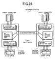
In another prior art as disclosed in JP-A-2001-256003,
as shown in Fig. 23, a single storage
system 1 is made up of a plurality of disk control
clusters 1-1 to 1-n. Each disk control cluster
includes a plurality of channel IF units 11 for
executing data transfer between the associated host
computer 3 and the associated disk control cluster, a
plurality of disk IF units 16 for executing data
transfer between the associated disk drive 2 and the
associated disk control cluster, and shared memory
units 25. An interconnection 31 is connected between
the channel IF units 11, disk IF units 16 and shared
memory units 25 in a plurality of disk control clusters
1-1 to 1-n. Stored in the shared memory units 25 are
control information on the storage system. The shared
memory units 25 are arranged so that the shared memory
units can be accessed by all the channel IF units 11
and disk IF units 12 via an interconnection 31, so that
exchange of the control information via the shared
memory units 25 enables the plurality of disk control
clusters to operate as a single storage system.
In large-scale companies such as typical
banks, securities companies and telephone companies,
computers and storages so far dispersed into local
places tend to be centralized into a data center to
form a computer system/storage system configuration,
thus reducing costs necessary for the operation,
maintenance and management of the computer system and
storage system.
In such a tendency, a large-scale/high-end
disk controller is required to support a channel
interface for connection with hundreds of host
computers (connectivity) and to support a storage
capacity of hundreds of tera-bytes or more.
Meanwhile, with expansion of open market and
spread of the storage area network (SAN) in these
years, demands of appearance of disk controllers of a
small-scale configuration (small-scale rack) with rich
functions/high reliability similar to the large-scale/high-end
disk controller have been stronger.
For the former demand, it is considered to
connect a plurality of such conventional large-scale/high-end
disk controllers to form a huge storage
configuration.
For the latter demand, it is considered to
minimize its rack in a minimum configuration model of
the conventional large-scale/high-end disk controller.
When a plurality of such minimized controllers are
connected, further, a storage system is considered
which can support a medium-to-large scaled
configuration supported by the conventional disk
controller.
As has been mentioned above, a storage system
is required to have a small- to huge-scale
configuration compatible with a reliable architecture
with a good scalability. To this end, such a storage
system is required that a plurality of disk controllers
can be clustered and be operated as a single system.
In the prior art shown in Fig. 2, the
plurality of disk controllers 4 are connected to the
host computers 3 via the SAN switch 5 so that the SAN
appliance 6 causes the host computers 3 to look the
disk controllers 4 like a single storage system.
However, the prior art has a problem that,
since the plurality of disk controllers 4 are operated
as a single system under control of software operating
on the SAN appliance 6, the prior art is lower in
reliability and availability than the conventional
single large-scale disk controller. Another problem is
that, since the SAN appliance 6 searches the disk
controllers 4 for data present therein and demanded by
the host computers 3, the performance of the prior art
becomes low.
When an error occurs in the channel IF units
11 of one disk controller 4 and it become impossible to
access data of the disk drive connected to this disk
controller, furthermore, it becomes necessary to once
stop the access from the host computer 3 to the disk
controller 4 and to exchange the channel IF unit 11,
with the result that this disadvantageously affects an
application program running under control of the host
computer 3.
The prior art shown in Fig. 23 provides a
storage system with a high scalability wherein the
plurality of disk control clusters exchange control
information via the shared memory units 25 and operate
as a single storage system.
This prior art however has a defect that its
bad handleability to users. In other words, in order
to enhance the performance, it is necessary that a
storage area to be assigned to the host computer 3 be a
storage area on the disk drive 2 connected to the disk
control cluster connected with the host computer 3.
Further, for the purpose of preventing impossible
access to the disk control cluster due to an interface
error between the host computer 3 and disk control
cluster, it becomes necessary to connect connection
paths from one host computer to the plurality of disk
control clusters. In addition, even when the plurality
of connection paths are connected, it is impossible to
perform switching between the connection paths without
notifying it to the host computer.
SUMMARY OF THE INVENTION
It is therefore an object of the present
invention to provide a storage system with a good
scalability which can be compatible with an identical
high reliability/high performance architecture from a
small scale configuration to a huge scale
configuration.
A specific object of the present invention is
to provide a storage system into which a plurality of
disk controllers are combined and has a high
reliability, high performance and good handleability.
The above object is attained by providing a
storage system which includes a plurality of disk
control clusters, each of the plurality of disk control
clusters having one or a plurality of channel interface
units having interfaces with host computers, one or a
plurality of disk interface units having interfaces
with disk drives, and a local shared memory unit for
storing data to be read/written from/to the disk
drives, control information about transfer of data and
management information about the disk drives, the
channel interface units executing data transfer between
the interfaces with the host computers and the local
shared memory units in response to a read/write request
from the host computers, the disk interface units
executing data transfer between the disk drives and the
local shared memory units to read/write the data;
a global information control unit for storing
the data to be read/written from/to the disk drives and
the management information about the disk control
clusters;
an interconnection connected between the
plurality of disk control clusters; and
a switch for connecting the channel interface
units in the plurality of disk control clusters,
wherein the switch has a memory to which the
management information stored in the global information
control unit is copied.
The above object is further attained by
providing a storage system wherein connection units for
connecting the channel interface units, the disk
interface units and the local shared memory unit in one
of the disk control clusters are connected to
corresponding connection units of the other disk
control clusters by means of the interconnection, and
the global information control unit is connected to the
interconnection and the switch.
The object is attained also by providing a
storage system wherein the channel interface units and
the disk interface units are directly connected to the
local shared memory unit in each of the disk control
clusters, the local shared memory unit in the disk
control cluster is connected to the local shared memory
units in the other disk control clusters by means of
the interconnection, and the global information control
unit is connected to the interconnection and the
switch.
The object is attained also by providing a
storage system wherein the channel interface units and
the disk interface units are connected directly to the
local shared memory unit in each of the disk control
clusters, connection units for connecting the channel
connection units and the disk interface units in one of
the disk control clusters are connected to
corresponding connection units of the other disk
control clusters by means of the interconnection, and
the global information control unit is connected to the
interconnection and the switch.
The object is attained also by providing a
storage system which includes,
a plurality of disk control clusters, each of
the plurality of disk control clusters having one or a
plurality of channel interface units having interfaces
with host computers, one or a plurality of disk
interface units having interfaces with disk drives, and
a local shared memory unit for storing data to be
read/written from/to the disk drives, control
information about transfer of data and management
information about the disk drives, the channel
interface units executing data transfer between the
interfaces with the host computers and the global
information control unit in response to a read/write
request from the host computers, the disk interface
units executing data transfer between the disk drives
and the global information control unit to read/write
the data;
an interconnection connected between the
plurality of disk control clusters; and
a switch for connecting the channel interface
units in the plurality of disk control clusters,
wherein the switch has a memory to which the
management information stored in the global information
control unit is copied.
The object is attained also by providing a
storage system wherein connection units for connecting
the channel interface units and the disk interface
units in one of the disk control clusters are connected
to corresponding connection units of the other disk
control clusters by means of the interconnection, and
the global information control unit is connected to the
switch by means of the interconnection.
The object is attained also by providing a
storage system which includes a plurality of disk
control clusters, each of the plurality of disk control
clusters having one or a plurality of channel interface
units having interfaces with host computers, one or a
plurality of disk interface units having interfaces
with disk drives, and a local shared memory unit having
first and second memories, the first memory storing
data to be read/written from/to the disk drives, the
second memory storing control information about data
transfer between the channel interface units and the
disk interface units and the first memory and also
storing management information about the disk drives,
the channel interface units executing the data transfer
between the interfaces with the host computers and the
first memory of the local shared memory units in
response to a read/write request from the host
computers, the disk interface units executing the data
transfer between the disk drives and the first memory
of the local shared memory units to read/write the
data;
a global information control unit for storing
management information about the disk control clusters;
two first and second different
interconnections for interconnecting the plurality of
disk control clusters; and
a switch for connecting the channel interface
units in the plurality of disk control clusters,
wherein the switch has a memory to which the
management information stored in the global information
control unit is copied.
The object is attained also by providing a
storage system wherein the channel interface units and
the disk interface units in each of the disk control
clusters are connected directly to the second memory in
the local shared memory unit in the disk control
cluster, first connection units for connecting the
channel interface units and the disk interface units in
one of the disk control clusters are connected to
corresponding first connection units of the other disk
control clusters via the first interconnection, second
connection units for connection the channel interface
units, the disk interface units and the first memory of
the local shared memory unit in one of the disk control
clusters are connected to corresponding second
connection units of other disk control clusters via the
second interconnection and the global information
control unit is connected to the first interconnection
and the switch.
Other objects of the present application and
how to solve the objects will become apparent from the
DETAILED DESCRIPTION OF THE EMBODIMENTS and the
attached drawings.
BRIEF DESCRIPTION OF THE DRAWINGS
Fig. 1 shows an arrangement of a storage
system in accordance with an embodiment 1 of the
present invention;
Fig. 2 shows a structure of a plurality of
disk controllers in a prior art;
Fig. 3 shows a detailed arrangement of the
storage system of the embodiment 1 of Fig. 1;
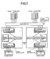
Fig. 4 shows an arrangement of a storage
system in accordance with an embodiment 2 of the
present invention;
Fig. 5 shows a detailed arrangement of the
storage system of the embodiment 2 of Fig. 4;
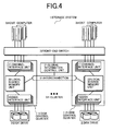
Fig. 6 shows an arrangement of a storage
system in accordance with an embodiment 3 of the
present invention;
Fig. 7 shows a detailed arrangement of the
storage system of the embodiment 3 of Fig. 6;
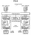
Fig. 8 shows an arrangement of a storage
system in accordance with an embodiment 4 of the
present invention;
Fig. 9 shows a detailed arrangement of the
storage system of the embodiment 4 of Fig. 8;
Fig. 10 shows an arrangement of a storage
system in accordance with an embodiment 5 of the
present invention;
Fig. 11 is a diagram for explaining a method
of increasing the number of disk control clusters in
the present invention;
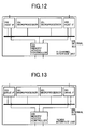
Fig. 12 shows a structure of a channel
interface unit forming the storage system of the
present invention;
Fig. 13 shows a structure of a disk interface
unit forming the storage system of the present
invention;
Fig. 14 shows another structure of the
channel interface unit forming the storage system of
the present invention;
Fig. 15 shows another structure of the disk
interface unit forming the storage system of the
present invention;
Fig. 16 shows an example of configuration
information of the storage system stored in a global
information control unit;
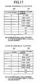
Fig. 17 shows another example of the
configuration information of the storage system stored
in a global information control unit;
Fig. 18 shows an example of
configuration/operation status of the storage system
stored in the global information control unit;
Fig. 19 shows an example of a table for
switch change-over control stored in a front-end
switch;
Fig. 20 shows another example of the
configuration/operation status of the storage system
stored in the global information control unit;
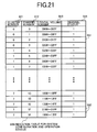
Fig. 21 shows a further example of the
configuration/operation status of the storage system
stored in the global information control unit;
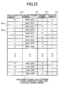
Fig. 22 shows another example of the table
for switch change-over control stored in the front-end
switch;
Fig. 23 shows an arrangement of a storage
system including a plurality of disk control clusters
in a prior art; and
Fig. 24 shows an arrangement of a storage
system in accordance with an embodiment 8 of the
present invention.
DETAILED DESCRIPTION OF THE EMBODIMENTS
Embodiments of the present invention will be
explained with reference to the accompanying drawings.
[Embodiment 1]
Embodiments of the present invention are
shown in Figs. 1, 3, 12 and 13.
In the following embodiments, explanation
will be made in connection with an example wherein a
switch is used as an interconnection. However, a bus
as an example may be employed so long as it can be
interconnected to perform transfer of configuration
information or data.
As shown in Fig. 1, a storage system 1
includes a plurality of disk control clusters 1-1 to 1-n
and a front-end switch 7.
The disk control cluster 1-1 has interface
units (channel interface units) 11 with an associated
host computer 3, interface units (disk IF units) 16
with disk drives 2, and local shared memory units 22.
An interconnection 31 across the disk control clusters
1-1 to 1-n are connected between the channel IF units
11, disk IF units 16 and local shared memory units 22.
A global information control unit 21 is connected to
the interconnection 31. That is, the storage system is
arranged to be accessed from all the channel IF units
11 and disk IF units 16 to the global information
control unit 21 via the interconnection.
The host computers 3 are connected to the
disk control clusters via the front-end switch 7 so
that any of the host computers 3 can access any of the
disk control clusters.
A specific example of each of the channel IF
units 11 is shown in Fig. 12.
The channel IF unit 11 has two IFs (host IFs)
202 with the associated host computer 3, two
microprocessors 201 for controlling input/output
to/from the host computer 3, and a memory access
controller 206 for controlling an access to the global
information control unit 21 or to the local shared
memory units 22. The channel IF unit 11 executes data
transfer between the associated host computer 3 and
global information control unit 21 or local shared
memory units 22 and transfer of configuration
information between the microprocessors 201 and global
information control unit 21 or local shared memory
units 22. The microprocessors 201 and host IFs 202 are
interconnected by an internal bus 205, and the memory
access controller 206 is directly connected to the two
host IFs 202 and also to the internal bus 205.
A specific example of a structure of each of
the disk IF units 16 is shown in Fig. 13.
The disk IF unit 16 has two interfaces (IFs)
(drive IFs) 203 with the associated disk drive 2, two
microprocessors 201 for controlling input/output
to/from the disk drive 2, and an access control unit
(memory access controller) 206 for controlling an
access to the global information control unit 21 or to
the local shared memory units 22. The disk IF unit 16
executes data transfer between the disk drive 2 and the
global information control unit 21 or local shared
memory units 22 and transfer of configuration
information between the microprocessors 201 and the
global information control unit 21 or local shared
memory units 22. The microprocessors 201 and the drive
IFs 203 are interconnected by the internal bus 205, the
memory access controller 206 are connected directly to
the two drive IFs 203 and also to the internal bus 205.
The disk IF unit 16 also executes a RAID function.
One disk control cluster may be configured as
a single rack or a module, but itself must have a
function as a single disk controller.
A specific example of the storage system is
shown in Fig. 3.
The storage system 1 includes two front-end
switches 7, a plurality of disk control clusters 1-1 to
1-n, a global information control unit 21, two global
switches (GSWs) 115, access paths 136, and access paths
137.
The global switches (GSWs) 115 function as
connection units which connect the paths from the
global information control unit 21 and the paths from a
plurality of disk control clusters.
Each of the disk control clusters 1-1 to 1-n
has two channel IF units 11 with host computers 3, two
disk IF units 16 with the associated disk drives 2, two
local switches (LSWs) 110, two local shared memory
units 22, access paths 131, access paths 132 and access
paths 136.
Each of the front-end switches 7 has a switch
71, a switch control unit 72, a memory controller 73,
and a memory module 105.
Each of the host computers 3 is connected by
each one path to the two switches 71 of the two front-end
switch 7, and the switches 71 are connected by each
one path to disk control clusters 1-1 to 1-n.
Each of the global information control units
21 has an access control unit 101, a management unit
102, and a memory module 105. The global information
control unit 21 stores information about management of
the disk control clusters 1-1 to 1-n (including, e.g.,
information on storage areas to be managed by the disk
control clusters, information on loads, errors and
configurations of respective parts in the disk control
clusters).
Each of the local switches (LSWs) 110 is a
connection unit which connects the paths from the
channel IF units 11, the paths from disk IF unit 16,
and the paths from the local shared memory units 22.
Each of the local shared memory units 22 has
a memory controller 100 and a memory module 105. The
local shared memory unit 22 stores control information
about the disk control clusters (including, e.g.,
information on control of data transfer between the
channel IF units 11 and disk IF units 16 and the local
shared memory units 22 and management information about
data to be recorded in the associated disk drives 2) as
well as the data to be recorded in the disk drives 2.
The memory access controllers 206 in the
channel IF units 11 are connected to the respective two
different LSWs 110 by means of the two access paths
131.
The LSWs 110, which have two access paths
132, are connected to the respective memory controllers
100 in the two different local shared memory units 22
by means of the paths 132.
Accordingly, the memory controller 100 has a
total of two access paths 132 connected with the two
LSWs 110.
Thus one memory access controller 206 can
have two access routes to one memory controller 100.
As a result, even when an error takes place
in one of the access paths or LSWs 110, an access to
the local shared memory units 22 can be allowed via the
other access route, thus enabling improvement in a
fault tolerance.
Each of the LSWs 110 has a total of four
access paths 131 of two connected from the two channel
IF units 11 and two connected from the disk IF units
16.
Each LSW 110 also has the two access paths
132 connected to the two local shared memory units 22
and one access path 136 connected to the global switch
(GSW) 115.
Since the LSW 110 has such access paths as
connected in the aforementioned manner, the LSW 110 has
a function of routing requests issued from the four
access paths from the channel IF units 11 and disk IF
units 16 to the two the access paths leading to the
local shared memory units 22 within the own disk
control cluster and to one access path 136 leading to
the global switch (GSW) 115.
The global switch (GSW) 115 has access paths
136 connected to the disk control clusters and
corresponding in number to the number thereof.
The global switch (GSW) 115 also has a total
of two access paths each connected to each of the
access control units 101 within the two global
information control units 21.
In this way, one memory access controller 206
can have two access routes connected therefrom to one
access control unit 101.
As a result, even when an error occurs in one
of the access paths, LSW 110 or global switch (GSW)
115, an access can be allowed to the global information
control unit 21 via the other access route, with the
result that a fault tolerance can be improved.
Even when the global switch (GSW) 115 is not
used and the access paths 136 are directly connected to
the access control unit 101, this will involve no
problem from the viewpoint of embodying the present
invention. As a result, an overhead for data transfer
processing caused by the global switch (GSW) 115 can be
reduced and thus its performance can be improved.
When no global switch (GSW) 115 is used, for
the purpose of securing two access routes from one
memory access controller 206 to one access control unit
101 to improve a fault tolerance, two of the access
paths 136 are provided to the LSW 110 to be connected
with the different access control units 101.
The global switches (GSWs) 115 have two paths
connected to the memory controllers 73 within the two
front-end switches 7.
Connected to the memory controller 73 within
the front-end switch 7 are the switch control unit 72
and the memory module 105.
The switch control unit 72, which is
connected to the switch 71, refers to a routing table
showing channel connections between the channels of the
host computers 3 and the channels of the disk control
clusters and stored in the memory module 105, and
controls the change-over of the switch.
Further, the memory module 105 in the front-end
switch 7 has a copy of information, within the
global information control unit 21, about loads, errors
and addresses for storage areas of parts within the
disk control clusters 1-1 to 1-n, and the switch
control unit 72 modifies the routing table on the basis
of these information periodically or as necessary.
More specifically, the global information
control unit 21 stores such a system
configuration/operation status table 500 as shown in
Fig. 18 in the memory module 105 therein, and the
front-end switch 7 stores a copy of the table 500 in
the memory module 105.
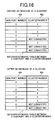
The system configuration/operation status
table 500 contains cluster numbers 511 for
identification of the disk control clusters, logical
volume numbers 513 associated with channel numbers 512
for identification of the channels of the disk control
clusters and channel operation status 514 associated
therewith.
In the present embodiment, the cluster number
511, channel number 512 and logical volume number 513
are expressed in hexadecimal notation. The channel
operation status 514 represents a low load condition by
'0', a medium load condition by '1', a high load
condition by '2', and an error by '3'.
The front-end switch 7 stores a host/logical
volume correspondence table 600 in the memory module
105 provided therein.
The host/logical volume correspondence table
600 contains logical volume numbers 513 associated with
host computer numbers 615 for identification of the
respective host computers, that is, logical volumes
assigned to the respective host computers, channel
numbers 512 for access to the logical volume numbers
513, and cluster numbers 511 of the disk control
clusters for management of the logical volumes.
As the host computer number 615, it is
considered to use a worldwide name (WWN) used in the
protocol of fiber channel or a MAC or IP address used
in the internet protocol.
The switch control unit 72 refers to the
host/logical volume correspondence table 600 (routing
table) and performs switching operation over the switch
71.
In Fig. 3, the LSW 110 is a connection unit
which connects the channel IF units 11, disk IF units
16 and local shared memory units 22, while the global
switch (GSW) 115 is a connection unit which connects
the disk control clusters 1-1 to 1-n and global
information control units 21.
In Fig. 3, the global switches (GSWs) 115 and
global information control units 21 may be mounted in a
box, the front-end switch 7 may be mounted in another
box, and these boxes may be mounted in a single rack
together with the disk control clusters 1-1 to 1-n each
in the form of a module. Further, the disk control
clusters 1-1 to 1-n may be mounted in separate racks
and located as distributed at locations distantly away.
In Fig. 3, explanation will be made in
connection with an example wherein the host computer 3
reads out data recorded in the storage system 1.
The host computer 3 first issues a data read
request to the storage system 1.
The request is accepted by the front-end
switch 7 so that the switch control unit 72 within the
front-end switch 7 analyzes the header of a request
packet.
The number (host computer number) of the host
computer as a request issuer and the logical volume
number having the request data recorded therein are
stored in the header of the request packet. The switch
control unit 72 refers to the host/logical volume
correspondence table 600, connects the port of the
switch 71 connected with the host computer as the
request issuer to the port of the switch 71 having a
channel number assigned to the corresponding logical
volume number, and sends the request packet to the disk
control cluster.
The microprocessor 201 within the channel IF
unit 11 connected with the request-sent channel
accesses the local shared memory unit 22 within the own
disk control cluster 1-1, and examines one of the disk
drives 2 in which the requested data is stored.
Since a conversion table showing the address
of the request data associated with the address of the
disk drive 2 having the data actually recorded therein
is stored in the local shared memory units 22, the
microprocessor 201 can examine one of the disk drives 2
having the requested data stored therein.
Further, the microprocessor 201 of the
channel IF unit 11 after receiving the request accesses
the local shared memory unit 22 within its own disk
control cluster 1-1, and confirms whether or not the
requested data is already stored in the local shared
memory unit 22.
Since the directory of the data is stored in
the local shared memory unit 22 together with data to
be stored in the disk drive 2, the microprocessor can
confirm the presence or absence of the request data in
the local shared memory unit 22.
When the microprocessor detects the presence
of the data in the local shared memory unit 22 of the
own disk control cluster 1-1, it accesses the local
shared memory unit 22, transfers the data to the
channel IF unit 11 via its own LSW 110, and sends it to
the host computer 3 via the front-end switch 7.
When the microprocessor 201 of the channel IF
unit 11 fails to detect the presence of the data in the
local shared memory unit 22 of the own disk control
cluster 1-1, the microprocessor issues control
information indicative of the processing contents of a
data request of reading the request data and storing it
in the local shared memory unit 22, the microprocessor
201 of the disk IF unit 16 when receiving the issued
control information reads out the data from the disk
drive 2 having the request data already stored therein,
transfers the request data to the local shared memory
unit 22 of the own disk control cluster 1-1 via the LSW
110, and stores it therein.
That is, the microprocessor 201 of the
channel IF unit 11 issues control information
indicative of the processing contents of the above data
request, and stores it in a control information area
(job control block) of the local shared memory unit 22.
The microprocessor 201 of the disk IF unit 16
watches the control information area of the local
shared memory unit 22 by polling and, when the above
issued control information is present in the above
control information area, the microprocessor reads out
the data from the disk drive 2 having the request data
stored therein, and transfers the request data to the
local shared memory unit 22 of the own disk control
cluster 1-1 via the LSW 110 to store the data therein.
After the microprocessor 201 of the disk IF
unit 16 stores the request data in the local shared
memory unit 22, transmits an address at which the data
was stored in the local shared memory unit 22 to the
microprocessor 201 of the channel IF unit 11 as the
issuer of the control information via the control
information within the local shared memory unit 22.
The microprocessor 201 of the channel IF unit 11 when
receiving the address reads out the data from the local
shared memory unit 22 and transmits the read data to
the host computer 3 via the front-end switch 7.
That is, the microprocessor 201 of the disk
IF unit 16 after storing the request data in the local
shared memory unit 22, issues control information
indicative of the end of the processing execution and
the data storage address, and stores the control
information in the control information area of the
local shared memory unit 22.
The microprocessor 201 of the channel IF
unit 11 which issued the above control information,
watches the control information area of the local
shared memory unit 22 by polling, and, when the control
information issued from the microprocessor 201 of the
disk IF unit 16 is present in the above control
information area, the microprocessor reads out the data
from the local shared memory unit 22 on the basis of
the data storage address in the local shared memory
unit, transfers it to the channel IF unit 11 and
further sends it to the host computer 3 via the front-end
switch 7.
In accordance with the present embodiment,
even when the host computer 3 is connected to any of
the connection ports of the front-end switch 7, the
host computer can write and read data only by issuing
an access request to the connection port without need
to be conscious of the disk control clusters of the
storage system 1. Thus this causes the plurality of
disk control clusters 1-1 to 1-n to look like a single
storage system to the host computer 3.
And there can be provided a storage system
which has a good scalability and handleability, ranging
from a small scale configuration including a single
disk control cluster to a huge scale configuration
including tens of connected disk control clusters,
compliant with an architecture having high reliability
and performance possessed by the single disk control
cluster.
[Embodiment 2]
An embodiment of the present invention is
shown in Figs. 4, 5, 12 and 13.
As shown in Fig. 4, the configuration of a
storage system 1 including disk control clusters 1-1 to
1-n and front-end switches 7 is the same as that of the
embodiment 1 of Fig. 1, except for a connection
configuration between channel IF units 11, disk IF
units 16, local shared memory units 22 and
interconnection 31.
In each of the disk control clusters, the
channel IF units 11, disk IF units 16 and local shared
memory units 22 are directly interconnected.
An interconnection 31 is wired between the
local shared memory units 22 in the plurality of disk
control clusters 1-1 to 1-n, and a global information
control units 21 are connected to the interconnection
31.
In the present embodiment, as mentioned
above, the channel IF units 11, disk IF units 16 and
local shared memory units 22 are directly connected in
each of the disk control clusters 1-1 to 1-n. As a
result, when compared with the case of the embodiment 1
having these units connected by the interconnection 31,
the present embodiment can shorten an access time to
the local shared memory unit 22.
The structures of the channel IF unit 11 and
disk IF unit 16 are substantially the same as those in
the embodiment 1 shown in Figs. 12 and 13.
Each of the disk control clusters may be
arranged in the form of a single rack or module, but
itself has a function as one disk controller.
A specific example of the storage system 1 is
shown in Fig. 5.
The structure of each of the disk control
clusters 1-1 to 1-n is also the same as that in the
embodiment 1 shown in Fig. 3, except for a connection
configuration between the channel IF units 11, disk IF
units 16 and local shared memory units 22 and for a
connection configuration between the disk control
clusters 1-1 to 1-n and global switches (GSWs) 115.
A storage system 1 includes a plurality of
disk control clusters 1-1 to 1-n, front-end switches 7,
global information control units 21, two global
switches (GSWs) 115, access paths 136, and access paths
137.
Each of the disk control clusters 1-1 to 1-n
has two channel IF units 11 as interfaces with the host
computers 3, two disk IF units 16 as interfaces with
the associated disk drive 2, two local shared memory
units 22, access paths 133 and access paths 136.
The two access paths 133 are connected to the
memory access controller 206 in each channel IF unit 11
to connect the memory access controller to the two
different memory controllers 100.
Therefore connected to the memory controller
100 are a total of four access paths 133 of two from
the two channel IF units 11 and two of the two disk IF
units 16. Also connected to the memory controller 100
is one access paths 136 leading to the global switch
(GSW) 115.
Since the memory controller 100 has such
access paths connected thereto as mentioned above, the
memory controller 100 has a function of routing
requests from the four access paths 133 issued from the
channel IF units 11 and disk IF units 16 to one access
path leading to the memory module 105 and to one access
path 136 lading to the global switch (GSW) 115.
Even when the access paths 136 are connected
directly to the access control units 101 without using
the global switches (GSWs) 115, this will involve no
problem from the viewpoint of embodying the present
invention. As a result, the overhead of the data
transfer processing generated by the global switches
(GSWs) 115 can be reduced and thus a performance can be
improved.
When the global switches (GSWs) 115 are not
used, for the purpose of securing an access route from
one memory controller 100 to one access control unit
101 to enhance a fault tolerance, two of the access
paths 136 are connected to the memory controller 100 to
connect it to different access control units 101.
As in the embodiment 1, in Fig. 5, the global
switches (GSWs) 115 and global information control unit
21 may be mounted in a box, the front-end switch 7 may
be mounted in another box, and these boxes may be
mounted in a single rack together with the disk control
clusters 1-1 to 1-n in the form of modules. Further,
the disk control clusters 1-1 to 1-n may be mounted in
individual racks and located as distributed at
locations distantly away from each other.
In the present embodiment, the operations of
the respective units within the storage system 1 when
data read/write operations are carried out from the
host computer 3 to the storage system 1 are the same as
those in the embodiment 1, except that access from the
channel IF unit 11 and disk IF unit 16 to the local
shared memory unit 22 is carried out directly and that
access from the channel IF unit 11 and disk IF unit 16
to the global information control unit 21 is carried
out through the memory controller 100.
In the present embodiment, even when the host
computer 3 is connected to any of the connection ports
of the front-end switch 7, the host computer can write
and read data only by issuing an access route to that
connection port while the disk control clusters of the
storage system 1 are made transparent to the host
computer, thereby causing the host computer to look the
plurality of disk control clusters 1-1 to 1-n like a
single storage system.
And there can be provided a storage system
which ranges from a small scale configuration including
a single disk control cluster to a huge scale
configuration including tens of connected disk control
clusters, which copes with an architecture having high
reliability and performance possessed by the single
disk control cluster, and which has a good scalability
and handleability.
[Embodiment 3]
Figs. 6, 7, 12 and 13 show an embodiment of
the present invention.
As shown in Fig. 6, the configuration of a
storage system 1 including disk control clusters 1-1 to
1-n and a front-end switch 7 is the same as that of the
embodiment 1 of Fig. 1, except for a connection
configuration between channel IF units 12, disk IF
units 17 and local shared memory units 22.
In each of the disk control clusters, the
channel IF unit 12, disk IF unit 17 and local shared
memory unit 22 are directly connected with each other.
Further, the channel IF units 12 and disk IF
units 17 of the plurality of disk control clusters 1-1
to 1-n are connected by an interconnection 31 to which
the global information control units 21 are connected.
As mentioned above, in the present
embodiment, the channel IF units 12, disk IF units 17
and local shared memory units 22 are directly connected
to each other in each of the disk control units 1-1 to
1-n. As a result, when compared with the case of the
embodiment 1 wherein these units are interconnected by
the interconnection 31, an access time to the local
shared memory unit 22 can be shortened.
The structures of the channel IF unit 12 and
disk IF unit 17 correspond to those of the channel IF
unit 11 and disk IF unit 16 shown in Figs. 12 and 13
respectively, but the number of access paths for the
memory access controller 206 are increased to 4.
In this case, two of the four access paths
are denoted by 131 and the other two are denoted by
133.
Each of the disk control clusters may be
arranged as a single rack or module, but itself must
have a function as a single disk controller.
A specific example of the storage system 1 is
shown in Fig. 7.
The structure of each of the disk control
clusters 1-1 to 1-n is also the same as that in the
embodiment 1 of Fig. 3, except for a connection
configuration between the channel IF units 12, disk IF
units 17 and local shared memory units 22.
The storage system 1 includes a plurality of
disk control clusters 1-1 to 1-n, front-end switches 7,
global information control units 21, two global
switches (GSWs) 115, access paths 136, and access paths
137.
Each of the disk control clusters 1-1 to 1-n
has two channel IF units 12 as interfaces with the host
computers 3, two disk IF units 17 as interfaces with
the associated disk drives 2, two local switches (LSWs)
110, two local shared memory units 22, access paths
131, access paths 133, and access paths 136.
The LSW 110 is a connection unit which
connects paths from the channel IF units 12 and paths
from the disk IF units 17.
The access paths 133, two of which are
connected to each of memory access controllers 206 of
the channel IF units 12 and disk IF units 17, are
connected to two different memory controllers 100.
Accordingly a total of four access paths 133 of two
from the two channel IF units 12 and two from the two
disk IF units 17 are connected to the memory controller
100.
Further, the access paths 131, two of which
are connected to each of the memory access controllers
206 within the channel IF units 12 and disk IF units
17, are connected at their other ends to the two
different LSWs 110. Accordingly a total of four access
paths 131 of two from the two channel IF units 12 and
two from the disk IF units 17, are connected to the LSW
110. The LSW 110 also has one access path 136
connected to the global switch (GSW) 115.
As in the embodiment 1, even when the global
switches (GSWs) 115 are not used and the access paths
136 are directly connected to the access control units
101, this will not involve any trouble from the
viewpoint of embodying the present invention. With it,
the overhead for the data transfer processing generated
by the global switches (GSWs) 115 can be reduced and
thus a performance can be improved.
When the global switches (GSWs) 115 are not
used, for the purpose of securing two access routes
from one LSW 110 to one access control unit 101 to
improve its fault tolerance, the LSWs 110 have two of
the access paths 136 to be connected to the different
access control units 101.
As in the embodiment 1, in Fig. 7, the global
switches (GSWs) 115 and global information control
units 21 may be mounted in a box, the front-end
switches 7 are mounted in another box, and these boxes
may be mounted in a single rack together with the disk
control clusters 1-1 to 1-n. Or the disk control
clusters 1-1 to 1-n may be mounted in individual racks
as distributed at locations distantly away from each
other.
In the present embodiment, the operations of
the respective units in the storage system 1 when data
read/write operation is carried out from the host
computer 3 to the storage system 1 are substantially
the same as those in the embodiment 1, except that
access from the channel IF units 12 and disk IF units
17 to the local shared memory unit 22 is carried out
directly.
In the present embodiment, even when the host
computer 3 is connected to any of the connection ports
of the front-end switch 7, the host computer 3 can
perform write and read operation only by issuing an
access request to that connection port while
eliminating the need for paying consideration to the
disk control clusters of the storage system 1, thus
causing the host computer 3 to look the plurality of
disk control clusters 1-1 to 1-n like a single storage
system.
And there can be provided a storage system
which ranges from a small scale configuration including
a single disk control cluster to a huge scale
configuration including tens of connected disk control
clusters, which copes with an architecture having high
reliability and performance possessed by the single
disk control cluster, and which has a good scalability
and handleability.
[Embodiment 4]
An embodiment of the present invention is
shown in Figs. 8, 9, 12 and 13.
As shown in Fig. 8, the configuration of a
storage system 1 including disk control clusters 1-1 to
1-n and front-end switches 7 is substantially the same
as that of the embodiment 1, except that the local
shared memory units 22 are removed in the embodiment 1.
To this end, all information to be stored in
the local shared memory unit 22 of each of the disk
control clusters 1-1 to 1-n in the embodiment 1 are
stored in the global information control unit 21.
The channel IF units 11 and disk IF unit 16
in the disk control clusters 1-1 to 1-n are connected
by an interconnection 31 to which the global
information control units 21 are connected.
The structures of the channel IF unit 11 and
disk IF unit 16 are the same as those of the
corresponding units in the embodiment 1 shown in Figs.
12 and 13 respectively.
One disk control cluster may be arranged as a
single rack or module.
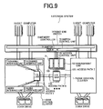
A specific example of the storage system 1 is
shown in Fig. 9.
The structure of each of the disk control
clusters 1-1 to 1-n is also the same as that of the
corresponding one in the embodiment 1 of Fig. 3, except
that the local shared memory units 22 are absent.
The storage system 1 includes a plurality of
disk control clusters 1-1 to 1-n, front-end switches 7,
global information control units 21, two global
switches (GSWs) 115, access paths 136, and access paths
137.
Each of the disk control clusters 1-1 to 1-n
has two channel IF units 11 as interfaces with the host
computers 3, two disk IF units 16 as interfaces with
the associated disk drives 2, two local switch (LSWs)
110, access paths 131, and access paths 136.
The LSW 110 is a connection unit which
connects paths from the channel IF units 11 and paths
from the disk IF units 16.
Each of the memory access controllers 206 in
the channel IF unit 11 and disk IF unit 16 has two
access paths 131 connected on the other ends with two
different LSWs 110.
Accordingly connected to the LSW 110 are a
total of four access paths 136 of two from the two
channel IF units 11 and two from the two disk IF units
16. Also the LSW 110 has one access paths 136
connected to the global switches (GSWs) 115.
As in the storage system 1, even when the
global switches (GSWs) 115 are not used and the access
paths 136 are connected directly to the access control
units 101, this will not involve any problem from the
viewpoint of embodying the present invention. As a
result, the overhead for the data transfer processing
generated by the global switches (GSWs) 115 can be
reduced and thus its performance can be improved.
In the case where the global switches (GSWs)
115 are not used, for the purpose of securing two
access routes from one LSW 110 to one access control
unit 101 to improve a fault tolerance, the LSWs 110
have two of the access paths 136 to be connected to the
different access control units 101.
As in the embodiment 1, in Fig. 9, the global
switches (GSWs) 115 and global information control
units 21 may be mounted in a box, the front-end
switches 7 are mounted in another box, and these boxes
may be mounted in a single rack together with the disk
control clusters 1-1 to 1-n in the form of a module.
Further, the disk control clusters 1-1 to 1-n may be
mounted in individual racks and located as distributed
at locations distantly away from each other.
In the present embodiment, the operations of
the respective units in the storage system 1 when data
read/write operation from the host computer 3 to the
storage system 1 is carried out, are substantially the
same as those of the corresponding ones in the
embodiment 1, except that all the processings of the
local shared memory units 22 in the embodiment 1 are
carried out by the global information control unit 21.
In the present embodiment, even when the host
computer 3 is connected to any of the connection ports
of the front-end switch 7, the host computer can
perform data write and read operation only by issuing
an access request to that connection port, while
eliminating the need for paying consideration to the
disk control clusters of the storage system 1, thus
causing the host computer 3 to look the plurality of
disk control cluster 1-1 to 1-n like a single storage
system.
And there can be provided a storage system
which ranges from a small scale configuration including
a single disk control cluster to a huge scale
configuration including tens of connected disk control
clusters, which copes with an architecture having high
reliability and performance possessed by the single
disk control cluster, and which has a good scalability
and handleability.
[Embodiment 5]
An embodiment of the present invention is
shown in Fig. 10.
Explanation will be made in connection with
an example wherein the interconnection is made in the
form of a switch in the foregoing embodiment, but the
interconnection may be made in any form such as a bus,
so long as it can be interconnected to transfer control
information or data.
As shown in Fig. 10, a storage system 1
includes a plurality of disk control clusters 1-1 to 1-n
and front-end switches 7.
Each of the disk control clusters 1-1 to 1-n
has interface units (channel IF units) 13 as interfaces
with the host computers 3, interface units (disk IF
units) 18 as interfaces with an associated disk drive
2, and local shared memory units 22 each having a
memory 1 (memory 25') and a memory 2 (memory 26'). In
each of the disk control clusters, the channel IF units
13, disk IF units 18 and memories 2 are directly
connected to each other.
The channel IF units 13 and disk IF units 18
are also connected by an interconnection 1
(interconnection 32) wired across the plurality of disk
control clusters 1-1 to 1-n, and the global information
control units 21 are connected to the interconnection
32. In other words, all the channel IF units 13 and
disk IF units 18 are arranged to be able to access the
global information control units 21 via the
interconnection 32.
The channel IF units 13, disk IF units 18 and
memory 1 are also connected therebetween by an
interconnection 33 (interconnection 2) wired across the
plurality of disk control clusters 1-1 to 1-n.
The host computers 3 are connected to the
disk control clusters via the front-end switches 7 so
that any of the computers can access any of the disk
control clusters.
A specific example of one of the channel IF
units 13 is shown in Fig. 14.
Each of the channel IF units 13 has two IFs
(host IFs) 202 as interfaces with the host computer 3,
two microprocessors 201 for controlling input and
output to and from the host computer 3, an access
control unit 1 (memory access controller 1) 207 for
controlling an access to the global information control
unit 21 or memories 26' (memories 2), and an access
control unit 2 (memory access controller 2) 208 for
controlling an access to the memory 25' (memory 1).
The channel IF units 13 execute data transfer between
the host computers 3 and memories 1 and transfer of
control information between the microprocessors 201 and
global information control units 21 or memories 2.
The microprocessors 201 and host IFs 202 are
interconnected by an internal bus 205, the memory
access controller (controller 1) 207 is connected to
the internal bus 205, and the memory access controller
(controller 2) 208 are connected directly to the two
host IFs 202 and also to the internal bus 205.
A specific example of one of the disk IF
units 18 is shown in Fig. 15.
The disk IF unit 18 has two drive IFs 203 as
interfaces with the associated disk drive 2, two
microprocessors 201 for controlling input and output to
and from the disk drive 2, an access control unit 1
(memory access controller 1) 207 for controlling an
access to the global information control unit 21 or
memories 26' (memories 2), and an access control unit 2
(memory access controller 2) 208 for controlling an
access to the memory 25' (memory 1). The disk IF unit
18 executes data transfer between the disk drive 2 and
memory 1 and transfer of control information between
the microprocessors 201 and global information control
unit 21 or memory 2.
The microprocessors 201 and drive IFs 203 are
connected by an internal bus 205, the memory access
controller (controller 1) 207 is connected to the
internal bus 205, and the memory access controller
(controller 2) 208 is connected directly to the two
drive IFs 203 or to the internal bus 205. The disk IF
units 18 also executes a RAID function.
One disk control cluster may be made in the
form of a single rack or module, but itself must have a
function as one disk controller.
In the specific example of the storage
system, connection configurations between the channel
IF units 13 and disk IF units 18 and the memories 26
(memories 2), interconnection 32 (interconnection 1),
and global information control units 21 are
substantially the same as those of the corresponding
ones in the embodiment 3 of Fig. 7. Further,
connection configurations between the channel IF units
13 and disk IF units 18 and the memories 1 and
interconnection 33 (interconnection 2) are
substantially the same as those of the corresponding
ones in the embodiment 1 of Fig. 3, but the global
information control units 21 are removed in the
embodiment 1.
The front-end switch 7 has a switch 71, a
switch control unit 72, a memory controller 73 and a
memory module 105.
One host computer 3 has two paths connected
to the switches 71 in the two front-end switches 7, and
switches 71 have 'n' paths connected to the disk
control clusters 1-1 to 1-n.
The global information control unit 21 has an
access control unit 101, a management unit 102 and a
memory module 105. And the global information control
unit 21 stores management information (e.g., storage
area information managed by the respective disk control
clusters, or load, error and configuration information
about respective parts in the disk control clusters) of
the disk control clusters 1-1 to 1-n therein. The
memory 1 temporarily stores therein data to be recorded
in the disk drive 2. The memory 2 also stores therein
control information (e.g., information on data transfer
control between the channel IF units 13 and disk IF
units 18 and the memories 25' (memories 1) and
management information about data to be recorded in the
disk drive 2) about the disk control clusters.
The front-end switch 7, which stores
information similar to in the embodiment 1 in the
memory module 105 provided therein, performs a similar
control to in the embodiment 1.
The global information control unit 21 also
stores information and table similar to those in the
embodiment 1 in the memory module 105 provided therein.
In Fig. 10, switches forming an
interconnection 32 (interconnection 1) outside of the
disk control clusters, switches forming an
interconnection 33 (interconnection 2) outside of the
disk control clusters, and the global information
control units 21 may be mounted in a box, the front-end
switches 7 may be mounted in another box, and these
boxes may be mounted in a single rack together with the
disk control clusters 1-1 to 1-n in the form of
modules. Further the disk control clusters 1-1 to 1-n
may be located as distributed at locations distantly
away from each other.
In Fig. 10, explanation will be explained in
connection with an example wherein the host computer 3
reads out data recorded in the storage system 1.
First of all, the host computer 3 issues a
data read request to the storage system 1.
The request is accepted by the front-end
switch 7 so that the switch control unit 72 within the
front-end switch 7 analyzes the header of the request
packet.
Stored in the header of the request packet
are the number (host computer number) of the host
computer which issued the request and a logical volume
number for the recorded request data. The switch
control unit 72 refers to the host/logical volume
correspondence table 600, connects the port of the
switch 71 connected with the host computer as the
request issuer to the port of the switch 71 having a
channel number assigned to the corresponding logical
volume number, and sends the request packet to the disk
control clusters.
The microprocessor 201 within the channel IF
unit 13 connected with the request send channel
accesses a memory 26 (memory 2) in its own disk control
cluster 1-1, and examines one of the disk drives 2 in
which the request data is stored. Since a conversion
table showing the address of the request data and an
address in the disk drive 2 at which the data is
actually recorded is stored in the memory 26 (memory
2), the microprocessor 201 can examine one of the disk
drives 2 in which the request data is stored. Further,
microprocessor 201 in the channel IF units 13 when
receiving the request accesses the memory 26 (memory 2)
in the own disk control cluster 1-1, and confirms
whether or not the request data is stored in the memory
25 (memory 1). The directory information on the data
stored in the memory 25 (memory 1) is stored in the
memory 26 (memory 2) and thus the presence or absence
of the request data in the memory 25 (memory 1) can be
confirmed.
As a result of the confirmation, if the data
is present in the memory 25 (memory 1) in the own disk
control cluster 1-1, then the data is transferred to
the channel IF unit 13 and then sent to the host
computer 3 via the front-end switch 7.
If the data is not present in the memory 25
(memory 1) in the own disk control cluster 1-1, then
the microprocessor 201 within the channel IF unit 13
reads out the request data from the microprocessor 201
within the disk IF unit 18 connected with the disk
drive 2 having the request data stored therein, issues
control information indicative of the processing
contents of the data request demanding storage of it in
the memory 25 (memory 1) to the microprocessor 201
within the disk IF unit 18. The microprocessor 201 of
the disk IF unit 18 when receiving the control
information reads out the data from the disk drive 2
having the request data stored therein, transfers the
request data to the memory 25 (memory 1) within the
own disk control cluster 1-1, and stores therein.
That is, the microprocessor 201 of the
channel IF unit 13 issues the control information
indicative of the processing contents of the data
request and stores it in a control information area
(job control block) of the memory 26 (memory 2).
The microprocessor 201 of the disk IF unit 18
watches the control information area of the memory 26
(memory 2) by polling. When the issued control
information is present in the control information area
(job control block), the microprocessor reads out the
data from the disk drive 2 having the request data
stored therein, transfers the request data to the
memory 25 (memory 1), and stores it therein.
The microprocessor 201 within the disk IF
unit 18, after storing the request data in the memory
25 (memory 1), transmits the address of the data stored
in the memory 25 (memory 1) to the microprocessor 201
within the channel IF unit 13 as the control
information issuer in the form of control information
within the memory 26 (memory 2). The microprocessor
201 within the channel IF unit 13 after receiving the
address read out the data from the memory 25 (memory 1)
and sends it to the host computer 3 via the front-end
switch 7.
That is, the microprocessor 201 of the disk
IF unit 18, after storing the request data in the
memory 25 (memory 1), issues control information
indicative of the end of the processing execution and
the data storage address, and stores it in the control
information area of the local shared memory unit 22.
The microprocessor 201 of the channel IF unit
13 after issuing the control information watches the
control information area of the memory 26 (memory 2) by
polling. When the control information issued from the
microprocessor 201 of the disk IF unit 18 is present in
the control information area, the microprocessor reads
out the data from the memory 25 (memory 1) on the basis
of the address at which the data is stored in the
memory 25 (memory 1), transfers the data to the channel
IF unit 13, and further sends it to the host computer 3
via the front-end switch 7.
Since the control information is different in
data length from the data by thousands of times, a time
necessary for one-time transfer of the control
information is remarkably different from a time
necessary for one-time transfer of the data. For this
reason, when the same interconnection and memory are
employed, the both will block the transfer of the
control information and data. According to the present
embodiment, the interconnection 32 (interconnection 1)
for transfer of the control information and the
interconnection 33 (interconnection 2) for transfer of
the data can be dividedly provided. As a result, it
can be avoided that the transfer of the control
information be blocked by the transfer of the data,
thus improving a performance.
[Embodiment 6]
Figs. 11, 16 and 17 show an example of a
procedure of increasing the number of disk control
clusters in the storage system 1 of the embodiment 1.
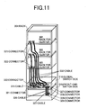
As shown in Fig. 11, a global switch box 310,
a front-end switch box 315 and individual cluster racks
302 are mounted in a rack 301.
Incorporated in the global switch box 310 are
global switches (GSWs) 115 and global information
control units 21.
The global switch box 310 has eight
connectors 321 and eight connectors 322, through which
eight disk control clusters can be connected. The
drawing shows a case where three disk control clusters
are connected to the global switch box 310.
The access paths 136 of the GSWs 115 are
connected to the connectors 321 and 322 in one-by-one
relationship.
The global switch box 310 has two connectors
326 and two connectors 327, through which the box 310
are connected with the front-end switch box 315.
Two connection paths for connection of one
access control unit 101 of the global information
control unit 21 to two memory controllers 73 of the
front-end switches 7 are connected to the two
connectors 326. Two connection paths for connection of
the other access control unit 101 to the two memory
controllers 73 of the front-end switch 7 are connected
to the two connectors 327.
Incorporated in the front-end switch box 315
is the front-end switches 7.
The front-end switch box 315 has two
connectors 328 and two connectors 329, through which
the box 315 is connected to the global switch box 310.
Two connection paths for connection of one of
the memory controllers 73 of the front-end switches 7
to the two access control units 101 of the global
information control units 21 are connected to the two
connectors 328. Further, two connection paths for
connection of the other memory controller 73 to the two
access control units 101 of the global information
control units 21 are connected to the two connectors
329.
The aforementioned number has been given only
as an example and is not limited to the above example.
The disk control clusters 1-1 to 1-3 are
mounted in the respective cluster racks 302. Each of
the cluster racks 302 has a connector 321 and a
connector 322, to which the two access paths 136 are
connected in a one-by-one relationship.
The connectors 321 and connectors 322 of the
cluster racks 302 are connected to the global switch
box 310 via cables 331 and cables 332.
Further, the connectors 328 and connectors
329 of the front-end switch box 315 are connected to
the connectors 326 and connectors 327 of the global
switch box 310 via cables 336 and cables 337.
Now the two cables 336 connected to the two
connectors 326 are connected to the connector 328 and
the connector 329 in a one-by-one relationship
therebetween. Similarly two cables 337 connected to
the connectors 327 are connected to the connector 328
and 329 in a one-by-one relationship therebetween. In
this manner, the two connection paths of the access
control units 101 are connected to the two memory
controllers 73 in a one-by-one relationship
therebetween.
In the storage system 1, the number of disk
control clusters is increased in a procedure which
follows. When the global switch box 310 has remaining
idle connectors for the increased disk control
clusters, the cables 331 and 332 are connected to the
idle connectors.
When such idle connectors are absent, a
global switch box having only the GSW mounted therein
is prepared, a plurality of such global switch boxes
are connected in multiple stages, and the cables 331
and 332 are connected to connectors of the boxes.
Simultaneously with the above, a GSW
port/cluster correspondence table 400 indicating the
disk control clusters to be connected to the ports of
the GSWs 115, that is, showing the disk control
clusters forming the storage system 1 as shown in Fig.
16 as well as a cluster/logical volume correspondence
table 405 showing logical volumes to be managed by the
disk control clusters as shown in Fig. 17 are
rewritten.
The GSW port/cluster correspondence tables
400 and the cluster/logical volume corresponding table
405 are stored in the global information control unit
21 to be rewritten by a service processor (SVP).
In many cases, a notebook type personal
computer is usually used as the SVP, so that such
tables as shown in Figs. 16 and 17 are displayed on a
display screen of the notebook computer and the
contents thereof are rewritten thereon.
Shown in Figs. 16 and 17 are GSW port/cluster
correspondence tables 400 and the cluster/logical
volume corresponding table 405 before and after an
increase of a disk control cluster.
In this case, the drawings show an example
where five disk control clusters are already provided
in the storage system 1 before the increase of the disk
control cluster and one disk control cluster is added.
As shown in Fig. 16, the port number 4 is
'not connected' in the GSW port number 401. After the
cable of cluster 5 is connected to that port, the 'not
connected' corresponding to the port number 4 in a row
of cluster number 402 is rewritten to '5' on the
display.
Thereafter, as shown in Fig. 17, 'not
connected' in a column of logical volume number 406
corresponding to the cluster number 5 of the cluster
number 402 is rewritten to '16640 to 20735'.
In this case, the logical volume number 406
shows a range of logical volumes to be managed by the
respective clusters.
A maximum value of the logical volume before
the increase is 16639 and the disk control cluster has
4096 logical volumes. Thus the range of the logical
volumes to be managed by the disk control cluster 5 is
'16640 to 20735'. The logical volumes can be numbered
not consecutively and as skipped, without any problem.
When the tables are arranged in such a manner
as mentioned above, a disk control cluster can be newly
added.
[Embodiment 7]
Figs. 18 to 21 show examples of operations of
the global control information part and front-end
switch 7 when the load of one of interfaces (channels)
of one channel interface unit with the host computer
became high in a storage system 1.
As shown in the embodiment 1, as an example,
the global information control unit 21 stores such a
system configuration/operation status table 500 as
shown in Fig. 18 in its memory module 105, and the
front-end switch 7 previously stores a copy of the
table 500 to the memory module 105.
The management unit 102 within the global
information control unit 21 periodically refers to
information about storage areas stored in the local
shared memory units 22 of the disk control clusters and
managed by the disk control clusters, load and error
information on respective parts within the disk control
clusters; and updates the system
configuration/operation status table 500.
Further, the switch control unit 72 within
the front-end switch 7 copies the table 500 to its own
memory module 105.
Meanwhile, at the time point that the
information of the storage areas stored in the local
shared memory unit 22 of each disk control cluster and
managed by the disk control cluster, or the load or
error information of the parts in the disk control
cluster was updated; the microprocessor within the
channel IF unit or disk IF unit may update the
corresponding information of the memory module 105 of
the global information control unit, and further at the
update time point, the management unit 102 may copy the
corresponding information to the memory module 105 of
the front-end switch 7. This is effective, in
particular, when an error took place one part within
the disk control unit.
The system configuration/operation status
table 500 contains a cluster number 511 for
identification of the disk control clusters, a logical
volume number 513 associated with a channel number 512
for identification of the channels of the disk control
clusters and a channel operation status 514 associated
with the channel number 512.
In the present embodiment, the cluster number
511, channel number 512 and logical volume number 513
are expressed each in hexadecimal notation. The
channel operation status 514 denotes its low load
condition by '0', a medium load condition by '1', a
high load condition by '2' and an error by '3'.
The front-end switch 7 stores the
host/logical volume correspondence table 600 in its
memory module 105 as it is.
The host/logical volume correspondence table
600 contains a logical volume number 513 corresponding
to the host computer number 615 for identification of
the host computers, that is, a logical volume assigned
to each host computer, a channel number 512 for access
to the logical volume number 513, and a cluster number
511 of the disk control cluster for management of the
corresponding logical volume.
As the host computer number 615, it is
considered to use, for example, a worldwide name (WWN)
used in a fiber channel protocol or a MAC or IP address
used in an Internet protocol.
As shown in Fig. 19, a range of a plurality
of discontinuous logical volumes can be assigned to one
host computer without any problem.
The switch control unit 72 refers to the
host/logical volume correspondence table 600 and
performs change-over operation over the switch 71.
As shown in Fig. 20, when the channel
operation status 514 at the #2 channel of the channel
number 512 was changed to '2' indicative of a high
load, part of '0100 to 01FF' of the logical volumes
assigned to the #2 channel is re-assigned to the '1F'
channel number corresponding to '0' indicative of a low
load of the channel operation status 514.
Fig. 21 show contents of the table 500 after
the aforementioned reassignment.
In the present embodiment, 0180 to 01FF
corresponding to half of the '0100 to 01FF' of the
logical volumes so far assigned to the #2 channel was
reassigned to the #'1F' channel. As a result, the
channel #2 operation status 514 is changed to '1'
indicative of a medium load, and the channel operation
status 514 corresponding to #'1F' channel is also
changed to '1' indicative of a medium load.
When such a table 500 as shown in Fig. 21 is
copied to the memory module 105 of the front-end switch
7, the switch control unit 72 refers to the table 500
and modifies the host/logical volume correspondence
table 600 as shown in Fig. 19.
Fig. 22 shows a table 600 after the above
modification.
In the table 500, since '0180 to 01FF' of the
logical volumes are assigned to the #`1F' channel, a
#'1F' channel is newly assigned to a#2 host computer
652.
As a result, when the #2 host computer 652
issued an access request to the logical volumes '0180
to 01FF', the switch is changed to the #'1F' channel.
In this case, the microprocessor of the
channel interface unit when receiving the access
request accesses the local shared memory unit and knows
that the request data is not present in its own disk
control cluster. In this case, however, the
microprocessor can know the disk control cluster having
the request data by accessing the global information
control unit, and thus can read out the request data
from the disk control cluster in question.
As a result, the loads of the channels of the
channel interface units in the storage system 1 can be
balanced while the host computers do not have to pay
consideration thereto and thus the entire performance
of the system can be improved.
Further, even in a case where some channel
having a channel number becomes unusable due to an
error by reassigning the logical volumes by the
aforementioned method, an access can be realized from
another channel to the data stored in the disk
controller of the target disk control cluster, while
eliminating the need for the host computer to pay
consideration to the channel error.
Further, when the load of the logical volume
of the disk drives connected to a disk control cluster
became high, the logical volume in question may, in
some cases, be copied or moved to the disk drives of
another disk control cluster for balancing the load.
Even in this case, however, by reassigning the logical
volume number and channel number in the table 500 by
the aforementioned method, the load of the logical
volume can be balanced while the host computer does not
have to pay consideration to it.
[Embodiment 8]
Fig. 24 shows an embodiment of the present
invention.
In the following embodiment, explanation will
be made in connection with an example wherein a switch
is used as an interconnection. However, any means such
as bus may be employed, so long as it can be wired to
be ale to transfer control information or data.
As shown in Fig. 24, a storage system 1
includes a plurality of disk control clusters 1-1 to 1-n
and front-end switches 7.
The storage system 1 of the present
embodiment is substantially the same as the storage
system of the embodiment 1 shown in Fig. 1, except that
the global information control units 21 and front-end
switches 7 are not connected directly to each other.
A specific example of the storage system
corresponds to the storage system 1 of Fig. 3 but the
access control units 101 and memory controllers 73 are
not provided.
As mentioned above, since the access control
units 101 and memory controllers 73 are not provided,
information about storage areas managed by the disk
control clusters within the global information control
units 21 as well as load and error information about
sites within the disk control clusters are copied to
the memory modules 105 of the front-end switches 7 via
channel IF units 11 and switches 71.
The copying operation is carried out by the
global information control unit 21 of the front-end
switch 7 issuing a processing request to the
microprocessor of the channel IF unit 11 via the
channel IF unit 11 and switch 71.
For example, when the above connection paths
can pass an Internet protocol therethrough, the above
information can be acquired by a simple network
management protocol (SNMP).
In accordance with the present embodiment,
the need for connecting the front-end switch 7 and
global information control unit 21 can be eliminated
and the mounting of racks forming the storage system
can be simplified.
In accordance with the present invention,
there can be provided a storage system wherein a
plurality of disk control clusters can be operated as a
single system, and which ranges from a small scale
configuration including a single disk control cluster
to a huge scale configuration including tens of
connected disk control clusters, which copes with an
architecture having high reliability and performance
possessed by the single disk control cluster, and which
has a good scalability and handleability.
It should be further understood by those
skilled in the art that although the foregoing
description has been made on embodiments of the
invention, the invention is not limited thereto and
various changes and modifications may be made without
departing from the spirit of the invention and the
scope of the appended claims.