EP1347388A1 - Coupling device for connecting devices to a bus system - Google Patents
Coupling device for connecting devices to a bus system Download PDFInfo
- Publication number
- EP1347388A1 EP1347388A1 EP03003435A EP03003435A EP1347388A1 EP 1347388 A1 EP1347388 A1 EP 1347388A1 EP 03003435 A EP03003435 A EP 03003435A EP 03003435 A EP03003435 A EP 03003435A EP 1347388 A1 EP1347388 A1 EP 1347388A1
- Authority
- EP
- European Patent Office
- Prior art keywords
- coupling device
- contact elements
- contact element
- variable
- fixed contact
- Prior art date
- Legal status (The legal status is an assumption and is not a legal conclusion. Google has not performed a legal analysis and makes no representation as to the accuracy of the status listed.)
- Granted
Links
Images


Classifications
-
- G—PHYSICS
- G05—CONTROLLING; REGULATING
- G05B—CONTROL OR REGULATING SYSTEMS IN GENERAL; FUNCTIONAL ELEMENTS OF SUCH SYSTEMS; MONITORING OR TESTING ARRANGEMENTS FOR SUCH SYSTEMS OR ELEMENTS
- G05B19/00—Programme-control systems
- G05B19/02—Programme-control systems electric
- G05B19/04—Programme control other than numerical control, i.e. in sequence controllers or logic controllers
- G05B19/042—Programme control other than numerical control, i.e. in sequence controllers or logic controllers using digital processors
- G05B19/0423—Input/output
-
- G—PHYSICS
- G05—CONTROLLING; REGULATING
- G05B—CONTROL OR REGULATING SYSTEMS IN GENERAL; FUNCTIONAL ELEMENTS OF SUCH SYSTEMS; MONITORING OR TESTING ARRANGEMENTS FOR SUCH SYSTEMS OR ELEMENTS
- G05B2219/00—Program-control systems
- G05B2219/20—Pc systems
- G05B2219/25—Pc structure of the system
- G05B2219/25335—Each module has connections to actuator, sensor and to a fieldbus for expansion
Definitions
- the present invention relates to a coupling device for connection of devices such as sensors, actuators, contactless protective devices (BWS), light barriers or controls to a bus system with at least one bus-side connection unit for connecting the coupling device to the bus system and with at least one device-side connection unit for connecting a Device to the coupling device, the device-side connection unit n (n> 1) comprises contact elements, each one of one Set of m (m> 1) predefined functional properties.
- Coupling devices of this type are used both for connecting Devices on normal bus systems as well as on safety bus systems used.
- IP 20 fieldbus connections (Connection units), which both connect passive safety switches as well as active safety light barriers on safety bus systems based on standard fieldbus protocols.
- a connector according to IP 67 M12 8-pin can be small wire cross sections lead only limited currents. These maximum currents are not sufficient for certain signal generators.
- Another The disadvantage is that the three plug connections mentioned are not can be assembled independently by the user, so that this Pre-assembled cables must be used, which gives the flexibility in the Local installation is limited and costs are increased.
- the connectors IP 67 M18 and IP 67 M23 have large dimensions and lead to higher connector costs on Signal generator and on the connection unit.
- the flexible connection for sensors of protection class IP 67 should be possible his.
- the requirements of the safety-related Integration of security components by security category 4 (EN 954) must be met.
- At least one Part of the contact elements is designed as a variable contact elements each can be variably assigned with one of the predefined functional properties are.
- each of the Contact elements a fixed, unchangeable predefined Has functional property is in the coupling device according to the invention thus a variability in the functional properties of the individual Contact elements, d. H. a parameterization of their function is possible. In this way it is achieved that for the usually in operation used devices coupling devices with a smaller number of contact elements can be used. In addition, single and Outputs are saved and there is increased flexibility for the user, since this automatically the coupling devices according to the invention can be reconfigured so that the connection of the desired devices is enabled.
- a cost-effective standard connector which according to the Invention can be used is, for example, a connector according to protection class IP 67 M12 5-pin.
- part of the Contact elements designed as fixed contact elements each fixed are each assigned a specified functional property, while the remaining contact elements each variable with a functional property are verifiable. Due to the fixed assignment of individual contact elements can the hardware and software effort in the development and Manufacturing of the coupling devices can be reduced. It is just note that a sufficient number of contact elements is designed as a variable contact elements to the required flexibility to connect the different devices can.
- variable Contact elements can be assigned the same functional property is or that at least some of the variable contact elements with each other different functional properties are verifiable.
- the each the desired configuration depends on the application.
- the number of device-side contact elements m can be greater than, equal to or be less than the number of predefined functional properties n.
- the choice of the appropriate number depends only on the desired application.
- the predefined functional properties from the following are advantageous Properties selectable: static supply voltage (positive or negative), ground (GND), signal input, test output, functional earth, Switching output, signal input with pull-up resistor, signal input with Pull down resistor, zero volts and no function.
- These predefined Functional properties are all essential combinations for the variable contact elements can be specified, so that in normal operation used devices on the coupling device according to the invention can be connected to any bus system.
- one of the Contact elements as a housing part of the device-side connection unit educated. This makes it possible to determine the actual number of pins used To further reduce the coupling plug. For example required six contact elements, so a standard connector in accordance with protection class IP 67 M12 5-pin, in which the Housing is used as the sixth contact element.
- the coupling device for connecting safe ones is preferred Devices (safety devices) trained.
- the coupling device is also preferred for connection to a safe bus system (safety bus system) educated.
- Housing contact permanently occupied with functional earth. Basically, however, it is also possible that with a sufficient number of contact elements Functional earth not on the housing contact, but on one separate contact pin is placed.
- a fixed contact element as first signal input (IN1), a fixed contact element as a second signal input (IN2) and a fixed contact element as Mass (GND) fixed while two variable contact elements each variable as first or second test output (TOUT1, TOUT2) adjustable or with static supply voltage or with zero volts are verifiable.
- TOUT1, TOUT2 first or second test output
- the coupling device according to the invention is the connection of safety switches, of safety light barriers as well from standard sensors to a safety bus system with a standardized Connector IP 67 M12 5-pin possible, as based on the figure description will be explained in more detail.
- a fixed contact element fixed to ground (GND)
- four variable contact elements each variable as any combination of signal inputs (IN1, IN2) and switching outputs (TOUT1, TOUT2) can be set.
- a solution alternative with an equivalent connection is also advantageous possible, with a fixed contact element with functional earth (FE) fixed contact element with ground (GND) and a fixed contact element with static supply voltage is set while two variable Contact elements each variable as signal inputs with pull-up resistance with pull-down resistor (IN1-pu, IN2-pu, IN1-pd, IN2-pd) are adjustable.
- FE functional earth
- GND ground
- two variable Contact elements each variable as signal inputs with pull-up resistance with pull-down resistor
- one of the variable signal inputs through a fixed contact element as signal input with pull-down resistor IN1-pd.
- the advantage of this Variant is that the connection of a non-contact Protective device and a safety switch on identical contact elements can take place and thus only four contact elements on the Coupling device are required. Therefore, the fifth contact element a 5-pin plug connection with functional earth. This can reduce the costs for a coupling device according to the invention can be further reduced. However, when connecting the BWS then programmed the signal inputs as
- the coupling device according to the invention ensures that for the connection of various types of standard and safety sensors a maximum of six contact elements are required. So that can also the connection technology according to protection class IP 67 with inexpensive M12 5-pin plug connections (optionally with functional earth on Housing) can be used.
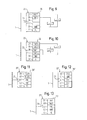
- Figure 1 shows a bus line 1 'of a bus system 1, to which an inventive Coupling device 2 is connected.
- the coupling device 2 Via the coupling device 2 are three different devices 3, 4, 5, for example a safety switch, a safety light barrier and a standard sensor connected to the bus line 1 '.
- a separate coupling device 2 for each device 3, 4, 5 is provided.
- multiple devices 3, 4, 5 can reduce the cost of the overall system be reduced.
- a coupling device is shown in each case in a highly schematic manner in FIGS 6 according to the prior art, each with a Bus-side connection unit 7 is connected to a bus system 1.
- the bus-side connection unit 7 Opposite the bus-side connection unit 7 is a highly schematic one device-side connection unit 8 is provided, which is usually is designed as a plug connection.
- the device-side connection unit 8 includes seven contact elements 9 - 15, which in practice as contact pins or contact holes of a connector or socket are trained.
- One of the contact elements can optionally also formed by the housing of the plug or the socket become.
- the contact element 9 with supply voltage (for example 24 volts) occupied, the contact element 10 as a test output 1 (TOUT1), the contact element 11 as a test output 2 (TOUT2), the contact element 12 as signal input 1 (IN1) formed, the contact element 13 designed as a signal input 2 (IN2), the contact element 14 with potential ground (GND) and the contact element 15 switched to functional earth (FE).
- supply voltage for example 24 volts
- TOUT1 test output 1
- TOUT2 test output 2
- the contact element 12 as signal input 1
- the contact element 13 designed as a signal input 2 (IN2)
- the contact element 14 with potential ground (GND) potential ground
- FE functional earth
- a coupling device can be used with the selected internal circuitry 6 according to the prior art for connecting a safety switch 16 (Figure 2), a safety light barrier 17 (Figure 3) or one testable standard sensor 18 ( Figure 4) can be used.
- a safety light barrier 17 (BWS) to the Bus system 1 can be connected.
- BWS safety light barrier 17
- the following signals or contacts are required: Power supply (24 volts), signal input 1 (IN1), signal input 2 (IN2), ground (GND) and functional earth (FE).
- FE functional earth
- the Contact elements 9 and 12 to 15 with these functional properties occupied, so that the connection of the safety light barrier 17 via the Coupling device 6 to the bus system 1 is possible.
- the safety light barrier 17 sends up automatically their signal outputs 19, 20 (OSSD Output Signal Switching Device according to IEC 61496) test sequences to determine the corresponding short and cross circuits to recognize.
- the same signal inputs IN1 and IN2 are used as in FIG. 2, with only one re-parameterization the corresponding evaluation software is required.
- testable standard sensor 18 When a testable standard sensor 18 according to FIG. 4 is connected The following signals are required on bus system 1: Power supply (24 volts), test output 1 (TOUT1), signal input 1 (IN1), ground (GND) and functional earth (FE). These functional characteristics will be 4 realized by the contact elements 9, 10, 12, 14 and 15, so that with the connection according to FIG. 4 also the operation of a testable one Standard sensor is possible.
- the sensor 18 is tested via the test output TOUT1.
- the Sensor 18 switches off its output 21 when the test signal is zero volts, see above that the function of the sensor 18 can be checked.
- the output signal of sensor 18 is read via signal input IN1.
- FIG. 5 shows a coupling device designed according to the invention 22 shown in highly schematic form as a block diagram.
- the coupling device 22 comprised a connection unit 23 on the bus side, via which it is connected is connected to the bus system 1.
- the internal connection unit is on the bus side 23 with two internal control units 24, 25 designed as CPUs connected.
- a device-side connection unit 26 which comprises six contact elements 27 to 32.
- the contact elements 27 to 30 are so-called variable contact elements trained, each internally with the control units 24, 25th are connected. Via the control units 24, 25 are each of the variable Contact elements 27 to 30 predetermined functional properties A, B, C, D assignable, these functional properties from a given Set of functional properties can be selected.
- the contact elements 31 and 32 are so-called fixed Contact elements formed, d. H. these two contact elements are with fixed predetermined functional properties, in the example according to FIG. 5, with the functional properties of mass (GND) and functional earth (FE) busy.
- connection lines 33 to 38 with corresponding inputs and outputs from Devices are connected, as follows with reference to Figures 6 to 15 is described in more detail.
- connection of the safety switch 16 from Figure 2 is on the coupling device 22 designed according to the invention is shown.
- the signals IN1, IN2, TOUT1 and TOUT2 required.
- the fixed contact elements 31, 32 are in not needed in this case.
- the safety switch 16 is thus read out or tested at Use of a coupling device designed according to the invention identical to the use of a coupling device according to the prior art Technology according to Figure 2, so that on the part of the user no change here is required.
- the contact element 27 is supplied with the supply voltage (24 Volts), the contact element 29 with IN1 and the contact element 30 with IN2 busy.
- the safety light barrier 17 is then connected identically according to the connection according to Figure 3, with the variable assignment of the individual functional properties to the contact elements 27 to 30 it is ensured that with the circuit shown in FIG desired functionality according to Figure 3 is achieved.
- the contact element 28 is not required in this connection, so that here this contact element 28 either with the standard value TOUT2 or with any other functional property can be wired. It is also possible that the contact element 28 is not connected in this case, as is shown in FIG. 7 by a cross is shown.
- the two-channel ones are tested Outputs OSSD1 and OSSD2 of the safety light barrier 17 with connected to the two signal inputs IN1, IN2.
- the power supply the safety light barrier takes place via the contact element 27 for example 24 volts.
- the safety light barrier covers the wiring 17 shorts between the two output lines OSSD1 and OSSD2 and short circuits to 24 volts or ground (GND) on.
- Figure 8 shows the parameterization of the designed according to the invention Coupling device when connecting the standard sensor 18 from FIG 4.
- the contact element 27 is powered (24 volts), the contact element 28 with TOUT2 and the contact element 29 with IN1.
- the contact element 30 is not required in this case and can be assigned, for example, by the standard value IN2 or also be not connected, as indicated by a cross in FIG. 8.
- circuitry is identical to the circuitry shown in FIG. 4, see above that with the corresponding parameterization of the contact elements 27 to 29 the same functionality as with the coupling device the prior art according to Figure 4 is achieved.
- the standard sensor 18 receives its voltage supply via the contact element 27 (24 volts). The sensor 18 is tested via the test output TOUT2 (contact element 28), while the switching output 21 of the Sensor is read via the contact element 29 (IN1).
- the two can be used for two-channel safety outputs Contact elements 27 and 28 as self-testing safe switching outputs TOUT1 and TOUT2 are executed.
- This allows the security category Reach 4 according to EN 954 or SIL 3 according to IEC 62508. If one lower security category is sufficient, the expression also take place in a single channel.
- the integrated control units in turn provide the necessary control 24 and 25 carried out, which by corresponding over the Bus system 1 transmitted control signals can be controlled.
- the two contact elements 27, 28 as high-active switching outputs TOUT1H and TOUT2H can be designed, while the two contact elements 29 and 30 parameterized as low-active switching outputs TOUT1L and TOUT2L as shown in Figure 10. It is still on it point out that in the entire description switching outputs that are not explicitly described otherwise, basically as high-active Switching outputs are to be understood. Basically, the invention however also with coupling devices with low-active switching outputs be used.
- the contact elements 31 and 32 not required, as can be seen from FIG. 10. Basically you can these in turn, as shown in Figure 5, formed as fixed contact elements his. However, it is also possible for all contact elements 27 to 32 are designed as variable contact elements, and thus an increased Get flexibility.
- FE functional earth
- FIGS. 11 to 15 differ compared to the embodiments according to FIGS. 6 to 10 in that only five contact elements 39 to 43 are provided. Accordingly the coupling devices with 22 'and the device-side connection units designated 26 '.
- Figures 11 to 15 show further possible parameterizations of the contact elements 39 to 43.
- the contact elements 39 and 40 as test outputs TOUT1, TOUT2, the contact elements 41 and 42 as Signal inputs IN1, IN2 and the contact element 43 as functional earth FE parameterized.
- the contact element 43 for example, not as a variable contact element, but as fixed contact element is formed, so the internal circuitry for the coupling device 22 'according to the invention. With the assignment shown in FIG A safety switch 16 according to FIG. 2 can be connected.
- the functional earth FE can be connected directly to the contact element 43, so that in this embodiment the use of the housing contact is not required. This can further reduce costs become.
- the contact element 39 with voltage supply the contact element 40 with signal input 1, the contact element 41 with signal input 2 and the contact element 42 is grounded (GND).
- the contact element 43 can in turn be assigned with functional earth either fixed or variable his.
- the contact elements 40 and 41 are included as signal inputs internal pull-down resistor or with internal pull-up resistor executed as it is characterized by the designations IN1-pd and IN2-pu is.
- the Contact elements 39 and 42 as fixed contact elements with that shown Train occupancy and only the contact elements 40 and 41 as variable To provide contact elements.
- the safety light barrier is connected 17 possible on the identical contact elements, see above that in turn only four contact elements for the actual connection the safety light barrier are required and thus functional earth can be placed on the fifth contact element.
- the connection via the connector housing is again not required in this case.
Abstract
Description
Die vorliegende Erfindung betrifft eine Kopplungsvorrichtung zum Anschließen von Geräten wie beispielsweise Sensoren, Aktoren, berührungslos wirkende Schutzeinrichtungen (BWS), Lichtschranken oder Steuerungen an ein Bussystem, mit zumindest einer busseitigen Anschlusseinheit zum Anschließen der Kopplungsvorrichtung an das Bussystem und mit zumindest einer geräteseitigen Anschlusseinheit zum Anschließen eines Gerätes an die Kopplungsvorrichtung, wobei die geräteseitige Anschlusseinheit n (n > 1) Kontaktelemente umfasst, von denen jedes eine aus einer Menge von m (m > 1) vordefinierten Funktionseigenschaften besitzt.The present invention relates to a coupling device for connection of devices such as sensors, actuators, contactless protective devices (BWS), light barriers or controls to a bus system with at least one bus-side connection unit for connecting the coupling device to the bus system and with at least one device-side connection unit for connecting a Device to the coupling device, the device-side connection unit n (n> 1) comprises contact elements, each one of one Set of m (m> 1) predefined functional properties.
Kopplungsvorrichtungen dieser Art werden sowohl zum Anschließen von
Geräten an normale Bussysteme als auch an Sicherheitsbussysteme
verwendet. So existieren beispielsweise IP 20 - Feldbusanschaltungen
(Anschalteinheiten), welche sowohl den Anschluss von passiven Sicherheitsschaltern
als auch von aktiven Sicherheitslichtschranken an Sicherheitsbussysteme
basierend auf Standard-Feldbusprotokollen ermöglichen.Coupling devices of this type are used both for connecting
Devices on normal bus systems as well as on safety bus systems
used. For example, there are
Die Lösungsansätze für die Anschaltung der einzelnen Geräte an das Bussystem basiert bei der Schutzklasse IP 20 meist darauf, dass getrennte Kontaktelemente mit folgenden Funktionseigenschaften (Belegungen) zur Verfügung stehen:
- statische Versorgungsspannung (üblicherweise 24 Volt)
- Potential Masse (GND)
- Signaleingang 1 (IN1)
- Signaleingang 2 (IN2)
- Testausgang 1 (TOUT1)
- Testausgang 2 (TOUT2)
- Funktionserde (FE)
- static supply voltage (usually 24 volts)
- Ground potential (GND)
- Signal input 1 (IN1)
- Signal input 2 (IN2)
- Test output 1 (TOUT1)
- Test output 2 (TOUT2)
- Functional earth (FE)
Mit einer derart belegten Kopplungsvorrichtung ist die Anschaltung der drei wichtigsten Arten von Signalgebern, nämlich Sicherheitsschalter, Sicherheitslichtschranke und Standard-Sensor, an ein Sicherheitsbussystem möglich, wobei die Kopplungsvorrichtungen in allen drei Fällen identisch ausgebildet sein können. Falls diese Arten von Signalgeber in der Schutzklasse IP 67 angeschlossen werden sollen, so müssen aufgrund der geltenden Vorschriften mindestens folgende industriell standardisierte Steckverbinder verwendet werden:
- IP 67 M12 8-polig
- IP 67 M18 8-polig
- IP 67 M23 12-polig
- IP 67 M12 8-pin
- IP 67 M18 8-pin
- IP 67 M23 12-pin
Der Einsatz dieser industriell standardisierten Steckverbinder bringt jedoch folgende Probleme mit sich. Zum einen sind grundsätzlich diese drei genannten Steckverbindungen keine handelsüblichen Steckverbindungen für Standard-Sensoren, für die üblicherweise IP 67 M12 5-polig eingesetzt wird. Somit ist ein Anschluss von Standard-Sensoren nicht ohne weiteres möglich.The use of these industrially standardized connectors brings however, the following problems arise. On the one hand, these are basically three plug connections mentioned no standard plug connections for standard sensors, for which usually IP 67 M12 5-pin is used. This means that standard sensors are not connected easily possible.
Zum anderen kann ein Steckverbinder gemäß IP 67 M12 8-polig durch zu kleine Adernquerschnitte nur begrenzte Ströme führen. Diese Maximalströme sind für bestimmte Signalgeber nicht ausreichend. Ein weiterer Nachteil besteht darin, dass die genannten drei Steckverbindungen nicht selbständig durch den Anwender konfektionierbar sind, so dass dieser vorkonfektionierte Kabel verwenden muss, was die Flexibilität bei der Installation vor Ort eingrenzt und die Kosten erhöht.On the other hand, a connector according to IP 67 M12 8-pin can be small wire cross sections lead only limited currents. These maximum currents are not sufficient for certain signal generators. Another The disadvantage is that the three plug connections mentioned are not can be assembled independently by the user, so that this Pre-assembled cables must be used, which gives the flexibility in the Local installation is limited and costs are increased.
Die Steckverbinder IP 67 M18 und IP 67 M23 besitzen demgegenüber zu große Abmessungen und führen zu höheren Steckverbinderkosten am Signalgeber sowie an der Anschalteinheit.In contrast, the connectors IP 67 M18 and IP 67 M23 have large dimensions and lead to higher connector costs on Signal generator and on the connection unit.
Es ist eine Aufgabe der vorliegenden Erfindung eine Kopplungsvorrichtung der eingangs genannten Art so auszubilden, dass eine flexible Anschaltung von Sicherheits- und Standard-Sensoren mit standardisierten, kostengünstigen Steckverbindungen durchgeführt werden kann. Insbesondere soll das flexible Anschalten für Sensoren der Schutzklasse IP 67 möglich sein. Weiterhin sollen insbesondere die Anforderungen der sicherheitsgerichteten Integration von Sicherheitskomponenten nach Sicherheitskategorie 4 (EN 954) erfüllt werden.It is an object of the present invention to provide a coupling device of the type mentioned in such a way that a flexible connection of safety and standard sensors with standardized, inexpensive Plug connections can be carried out. In particular The flexible connection for sensors of protection class IP 67 should be possible his. Furthermore, the requirements of the safety-related Integration of security components by security category 4 (EN 954) must be met.
Ausgehend von einer Kopplungsvorrichtung der eingangs genannten Art wird diese Aufgabe erfindungsgemäß dadurch gelöst, dass zumindest ein Teil der Kontaktelemente als variable Kontaktelemente ausgebildet ist, die jeweils variabel mit einer der vordefinierten Funktionseigenschaften belegbar sind.Starting from a coupling device of the type mentioned This object is achieved in that at least one Part of the contact elements is designed as a variable contact elements each can be variably assigned with one of the predefined functional properties are.
Gegenüber den bekannten Kopplungsvorrichtungen, bei denen jedes der Kontaktelemente eine fest vorgegebene, unveränderbare vordefinierte Funktionseigenschaft besitzt, ist bei der erfindungsgemäßen Kopplungsvorrichtung somit eine Variabilität der Funktionseigenschaften der einzelnen Kontaktelemente, d. h. eine Parametrisierung deren Funktion, möglich. Auf diese Weise wird erreicht, dass für die im Betrieb üblicherweise eingesetzten Geräte Kopplungsvorrichtungen mit einer geringeren Anzahl von Kontaktelementen verwendet werden können. Zusätzlich können Einund Ausgänge eingespart werden und es entsteht eine erhöhte Flexibilität für den Anwender, da dieser selbsttätig die erfindungsgemäßen Kopplungsvorrichtungen so umparametrieren kann, dass der Anschluss der gewünschten Geräte ermöglicht wird.Compared to the known coupling devices, in which each of the Contact elements a fixed, unchangeable predefined Has functional property is in the coupling device according to the invention thus a variability in the functional properties of the individual Contact elements, d. H. a parameterization of their function is possible. In this way it is achieved that for the usually in operation used devices coupling devices with a smaller number of contact elements can be used. In addition, single and Outputs are saved and there is increased flexibility for the user, since this automatically the coupling devices according to the invention can be reconfigured so that the connection of the desired devices is enabled.
Letztlich ist auch die Verwendung von bereits bestehenden Gehäusen und Anschluss-Steckverbindern bei existierenden Bussystem bzw. Geräten möglich. Eine kostengünstige Standard-Steckverbindung, die gemäß der Erfindung Verwendung finden kann, ist beispielsweise ein Steckverbinder gemäß Schutzklasse IP 67 M12 5-polig.Ultimately, the use of existing housings and Connection connectors for existing bus systems or devices possible. A cost-effective standard connector, which according to the Invention can be used is, for example, a connector according to protection class IP 67 M12 5-pin.
Nach einer vorteilhaften Ausführungsform der Erfindung ist ein Teil der Kontaktelemente als feste Kontaktelemente ausgebildet, die jeweils fest mit je einer vorgegebenen Funktionseigenschaft belegt sind, während die restlichen Kontaktelemente jeweils variabel mit je einer Funktionseigenschaft belegbar sind. Durch die feste Belegung einzelner Kontaktelemente kann der Hardware- und Softwareaufwand bei der Entwicklung und Herstellung der Kopplungsvorrichtungen reduziert werden. Dabei ist lediglich zu beachten, dass eine ausreichende Anzahl von Kontaktelementen als variable Kontaktelemente ausgebildet ist, um die benötigte Flexibilität zum Anschließen der unterschiedlichen Geräte gewährleisten zu können.According to an advantageous embodiment of the invention, part of the Contact elements designed as fixed contact elements, each fixed are each assigned a specified functional property, while the remaining contact elements each variable with a functional property are verifiable. Due to the fixed assignment of individual contact elements can the hardware and software effort in the development and Manufacturing of the coupling devices can be reduced. It is just note that a sufficient number of contact elements is designed as a variable contact elements to the required flexibility to connect the different devices can.
Mit der Erfindung ist es möglich, dass zumindest ein Teil der variablen Kontaktelemente jeweils mit der gleichen Funktionseigenschaft belegbar ist oder dass zumindest einige der variablen Kontaktelemente mit voneinander verschiedenen Funktionseigenschaften belegbar sind. Die jeweils gewünschte Konfiguration ist dabei von der Applikation abhängig. With the invention it is possible that at least part of the variable Contact elements can be assigned the same functional property is or that at least some of the variable contact elements with each other different functional properties are verifiable. The each the desired configuration depends on the application.
Die Anzahl der geräteseitigen Kontaktelemente m kann größer, gleich oder kleiner als die Anzahl der vordefinierten Funktionseigenschaften n sein. Auch hier hängt die Wahl der entsprechenden Anzahl lediglich von der gewünschten Applikation ab.The number of device-side contact elements m can be greater than, equal to or be less than the number of predefined functional properties n. Here too, the choice of the appropriate number depends only on the desired application.
Vorteilhaft sind die vordefinierten Funktionseigenschaften aus folgenden Eigenschaften wählbar: statische Versorgungsspannung (positiv oder negativ), Masse (GND), Signaleingang, Testausgang, Funktionserde, Schaltausgang, Signaleingang mit Pull-up-Widerstand, Signaleingang mit Pull-down-Widerstand, null Volt und keine Funktion. Mit diesen vordefinierten Funktionseigenschaften sind alle wesentlichen Kombinationen für die variablen Kontaktelemente vorgebbar, so dass die im üblichen Betrieb eingesetzten Geräte über die erfindungsgemäße Kopplungsvorrichtung an jedem Bussystem angeschlossen werden können.The predefined functional properties from the following are advantageous Properties selectable: static supply voltage (positive or negative), ground (GND), signal input, test output, functional earth, Switching output, signal input with pull-up resistor, signal input with Pull down resistor, zero volts and no function. With these predefined Functional properties are all essential combinations for the variable contact elements can be specified, so that in normal operation used devices on the coupling device according to the invention can be connected to any bus system.
Nach einer vorteilhaften Ausführungsform der Erfindung ist eines der Kontaktelemente als Gehäuseteil der geräteseitigen Anschlusseinheit ausgebildet. Dadurch ist es möglich, die eigentliche Pin-Anzahl des verwendeten Kopplungssteckers weiter zu reduzieren. Werden beispielsweise sechs Kontaktelemente benötigt, so kann ein Standard-Steckverbinder gemäß Schutzklasse IP 67 M12 5-polig verwendet werden, bei dem das Gehäuse als sechstes Kontaktelement eingesetzt wird.According to an advantageous embodiment of the invention, one of the Contact elements as a housing part of the device-side connection unit educated. This makes it possible to determine the actual number of pins used To further reduce the coupling plug. For example required six contact elements, so a standard connector in accordance with protection class IP 67 M12 5-pin, in which the Housing is used as the sixth contact element.
Bevorzugt ist die Kopplungsvorrichtung zum Anschluss von sicheren Geräten (Sicherheitsgeräte) ausgebildet. Ebenso ist bevorzugt die Kopplungsvorrichtung zum Anschluss an ein sicheres Bussystem (Sicherheitsbussystem) ausgebildet.The coupling device for connecting safe ones is preferred Devices (safety devices) trained. The coupling device is also preferred for connection to a safe bus system (safety bus system) educated.
Nach einer weiteren vorteilhaften Ausführungsform der Erfindung ist der Gehäusekontakt fest mit Funktionserde belegt. Grundsätzlich ist es jedoch auch möglich, dass bei einer ausreichenden Anzahl von Kontaktelementen Funktionserde nicht auf den Gehäusekontakt, sondern auf einen separaten Kontaktpin gelegt wird.According to a further advantageous embodiment of the invention Housing contact permanently occupied with functional earth. Basically, however, it is also possible that with a sufficient number of contact elements Functional earth not on the housing contact, but on one separate contact pin is placed.
Nach einer weiteren vorteilhaften Ausführungsform der Erfindung ist ein festes Kontaktelement als erster Signaleingang (IN1), ein festes Kontaktelement als zweiter Signaleingang (IN2) und ein festes Kontaktelement als Masse (GND) fest eingestellt, während zwei variable Kontaktelemente jeweils variabel als erster oder zweiter Testausgang (TOUT1, TOUT2) einstellbar oder mit statischer Versorgungsspannung oder mit null Volt belegbar sind. Bei dieser Ausführungsform sind somit zwei variable Kontaktelemente vorgesehen, die wahlweise als Testausgänge mit Testsequenzen verwendbar sind oder statisch auf Versorgungsspannung (beispielsweise 24 Volt oder null Volt) gelegt werden können. Mit dieser Ausführungsform der erfindungsgemäßen Kopplungsvorrichtung ist das Anschließen von Sicherheitsschaltern, von Sicherheitslichtschranken sowie von Standard-Sensoren an ein Sicherheitsbussystem mit einem standardisierten Steckverbinder IP 67 M12 5-polig möglich, wie anhand der Figurenbeschreibung näher erläutert werden wird.According to a further advantageous embodiment of the invention, a fixed contact element as first signal input (IN1), a fixed contact element as a second signal input (IN2) and a fixed contact element as Mass (GND) fixed while two variable contact elements each variable as first or second test output (TOUT1, TOUT2) adjustable or with static supply voltage or with zero volts are verifiable. In this embodiment there are thus two variable contact elements provided, optionally as test outputs with test sequences can be used or statically on supply voltage (for example 24 volts or zero volts). With this embodiment the coupling device according to the invention is the connection of safety switches, of safety light barriers as well from standard sensors to a safety bus system with a standardized Connector IP 67 M12 5-pin possible, as based on the figure description will be explained in more detail.
Auch die Realisierung von Kopplungsvorrichtungen mit zweipoligen Sicherheitsausgängen ist mit der erfindungsgemäßen Lösung möglich. Dazu werden in einer bevorzugten Ausführungsform ein festes Kontaktelement als Masse (GND) fest eingestellt, während zumindest ein Teil der übrigen Kontaktelemente als variable Kontaktelemente ausgebildet sind und jeweils zwei der variablen Kontaktelemente als erster und zweiter Testausgang (TOUT1H, TOUT2H) und die beiden anderen variablen Kontaktelemente als jeweils low-aktiver erster und zweiter Schaltausgang (TOUT1L, TOUT2L) einstellbar sind. Dabei ist es in einer alternativen Lösung auch möglich, dass der erste und zweite Testausgang (TOUT1H, TOUT2H) als feste Kontaktelemente ausgeführt sind.Also the implementation of coupling devices with two-pole safety outputs is possible with the solution according to the invention. To become a fixed contact element in a preferred embodiment fixed as mass (GND), while at least some of the rest Contact elements are designed as variable contact elements and each two of the variable contact elements as the first and second test output (TOUT1H, TOUT2H) and the other two variable contact elements as low-active first and second switching outputs (TOUT1L, TOUT2L) are adjustable. It is also in an alternative solution possible that the first and second test output (TOUT1H, TOUT2H) as fixed contact elements are executed.
Nach einer weiteren bevorzugten Ausführungsform ist ein festes Kontaktelement fest mit Masse (GND) belegt, während vier variable Kontaktelemente jeweils variabel als beliebige Kombination von Signaleingängen (IN1, IN2) und Schaltausgängen (TOUT1, TOUT2) einstellbar sind. Mit dieser Ausführungsform lassen sich Anschaltungsbeispiele für Sicherheitsschalter und Sicherheitslichtschranken auch mit nur fünf Kontaktelementen (ohne Gehäusekontakt) realisieren, wie anhand der Figurenbeschreibung noch näher ausgeführt werden wird.According to a further preferred embodiment, there is a fixed contact element fixed to ground (GND), while four variable contact elements each variable as any combination of signal inputs (IN1, IN2) and switching outputs (TOUT1, TOUT2) can be set. With This embodiment allows connection examples for safety switches and safety light barriers with only five contact elements realize (without housing contact), as with the description of the figures will be explained in more detail.
Vorteilhaft ist auch eine Lösungsalternative mit antivalenter Anschaltung möglich, wobei ein festes Kontaktelement fest mit Funktionserde (FE), ein festes Kontaktelement mit Masse (GND) und ein festes Kontaktelement mit statischer Versorgungsspannung festgelegt ist, während zwei variable Kontaktelemente jeweils variabel als Signaleingänge mit Pull-up-Widerstand mit Pull-down-Widerstand (IN1-pu, IN2-pu, IN1-pd, IN2-pd) einstellbar sind. Alternativ ist es hierzu auch möglich, dass einer der variablen Signaleingänge durch ein festes Kontaktelement als Signaleingang mit Pull-down-Widerstand IN1-pd fest belegt ist. Der Vorteil dieser Variante liegt darin, dass der Anschluss einer berührungslos wirkenden Schutzeinrichtung und eines Sicherheitsschalters an identischen Kontaktelementen erfolgen kann und somit nur vier Kontaktelemente an der Kopplungsvorrichtung erforderlich sind. Daher kann das fünfte Kontaktelement einer 5-poligen Steckverbindung mit Funktionserde belegt werden. Dadurch können die Kosten für eine erfindungsgemäße Kopplungsvorrichtung weiter verringert werden. Allerdings müssten beim Anschluss einer BWS die Signaleingänge dann als Pull-down-Eingänge programmiert werden. A solution alternative with an equivalent connection is also advantageous possible, with a fixed contact element with functional earth (FE) fixed contact element with ground (GND) and a fixed contact element with static supply voltage is set while two variable Contact elements each variable as signal inputs with pull-up resistance with pull-down resistor (IN1-pu, IN2-pu, IN1-pd, IN2-pd) are adjustable. Alternatively, it is also possible for one of the variable signal inputs through a fixed contact element as signal input with pull-down resistor IN1-pd. The advantage of this Variant is that the connection of a non-contact Protective device and a safety switch on identical contact elements can take place and thus only four contact elements on the Coupling device are required. Therefore, the fifth contact element a 5-pin plug connection with functional earth. This can reduce the costs for a coupling device according to the invention can be further reduced. However, when connecting the BWS then programmed the signal inputs as pull-down inputs become.
Durch die erfindungsgemäße Kopplungsvorrichtung wird erreicht, dass für die Anschaltung verschiedenster Arten von Standard- und Sicherheitssensoren maximal sechs Kontaktelemente benötigt werden. Damit kann auch die Anschlusstechnik gemäß Schutzklasse IP 67 mit kostengünstigen M12 5-poligen Steckverbindungen (wahlweise mit Funktionserde am Gehäuse) eingesetzt werden.The coupling device according to the invention ensures that for the connection of various types of standard and safety sensors a maximum of six contact elements are required. So that can also the connection technology according to protection class IP 67 with inexpensive M12 5-pin plug connections (optionally with functional earth on Housing) can be used.
Weitere vorteilhafte Ausführungsformen der Erfindung sind in den Unteransprüchen angegeben.Further advantageous embodiments of the invention are in the subclaims specified.
Die Erfindung wird nachfolgend anhand von Ausführungsbeispielen unter Bezugnahme auf die Zeichnungen näher beschrieben; in diesen zeigen:
Figur 1- ein Blockdiagramm eines Bussystems, an das über eine erfindungsgemäße Kopplungsvorrichtung drei unterschiedliche Geräte angeschlossen sind,
- Figuren 2 - 4
- schematische Darstellungen einer Kopplungsvorrichtung nach dem Stand der Technik mit verschiedenen Beschaltungen,
- Figur 5
- eine schematische Darstellung des Aufbaus einer erfindungsgemäß ausgebildeten Kopplungsvorrichtung und
- Figuren 6 - 15
- verschiedene Ausführungsformen einer erfindungsgemäß ausgebildeten Kopplungsvorrichtung mit unterschiedlichen Beschaltungen.
- Figure 1
- 2 shows a block diagram of a bus system to which three different devices are connected via a coupling device according to the invention,
- Figures 2-4
- schematic representations of a coupling device according to the prior art with various circuits,
- Figure 5
- is a schematic representation of the structure of a coupling device designed according to the invention and
- Figures 6 - 15
- Different embodiments of a coupling device designed according to the invention with different circuits.
Figur 1 zeigt eine Busleitung 1' eines Bussystems 1, an die eine erfindungsgemäße
Kopplungsvorrichtung 2 angeschlossen ist. Über die Kopplungsvorrichtung
2 sind drei unterschiedliche Geräte 3, 4, 5, beispielsweise
ein Sicherheitsschalter, eine Sicherheitslichtschranke und ein Standardsensor
mit der Busleitung 1' verbunden. Grundsätzlich ist es auch
möglich, dass für jedes Gerät 3, 4, 5 eine eigene Kopplungsvorrichtung 2
vorgesehen ist. Durch Verwendung einer Kopplungsvorrichtung 2 für
mehrere Geräte 3, 4, 5 können die Kosten des Gesamtsystems jedoch
herabgesetzt werden.Figure 1 shows a bus line 1 'of a
In den Figuren 2 bis 4 ist jeweils stark schematisiert eine Kopplungsvorrichtung
6 nach dem Stand der Technik dargestellt, die jeweils über eine
busseitige Anschlusseinheit 7 mit einem Bussystem 1 verbunden ist.A coupling device is shown in each case in a highly schematic manner in FIGS
6 according to the prior art, each with a
Bus-
Der busseitigen Anschlusseinheit 7 gegenüberliegend ist eine stark schematisierte
geräteseitige Anschlusseinheit 8 vorgesehen, die üblicherweise
als Steckverbindung ausgebildet ist. Die geräteseitige Anschlusseinheit 8
umfasst dabei sieben Kontaktelemente 9 - 15, die in der Praxis als Kontaktstifte
oder Kontaktlöcher eines Anschlusssteckers bzw. einer Anschlussbuchse
ausgebildet sind. Eines der Kontaktelemente kann gegebenenfalls
auch durch das Gehäuse des Steckers bzw. der Buchse gebildet
werden.Opposite the bus-
Bei den Kopplungsvorrichtungen 6 gemäß dem Stand der Technik nach
den Figuren 2 bis 4 ist dabei das Kontaktelement 9 mit Versorgungsspannung
(beispielsweise 24 Volt) belegt, das Kontaktelement 10 als Testausgang
1 (TOUT1) ausgebildet, das Kontaktelement 11 als Testausgang 2
(TOUT2) ausgebildet, das Kontaktelement 12 als Signaleingang 1 (IN1)
ausgebildet, das Kontaktelement 13 als Signaleingang 2 (IN2) ausgebildet,
das Kontaktelement 14 mit Potentialmasse (GND) belegt und das Kontaktelement
15 auf Funktionserde (FE) geschaltet. Diese interne Beschaltung
der einzelnen Kontaktelemente 9 bis 15 ist dabei fest und unveränderlich.In the
Mit der gewählten internen Beschaltung kann eine Kopplungsvorrichtung
6 gemäß dem Stand der Technik zum Anschließen eines Sicherheitsschalters
16 (Figur 2), einer Sicherheitslichtschranke 17 (Figur 3) oder eines
testbaren Standardsensors 18 (Figur 4) verwendet werden.A coupling device can be used with the selected
Um gemäß Figur 2 einen passiven bzw. kontaktbehafteten Sicherheitsschalter
16 über die Kopplungsvorrichtung 6 an das Bussystem 1 anschließen
zu können, werden folgende Signale benötigt: Signaleingang 1
(IN1), Signaleingang 2 (IN2), Testausgang 1 (TOUT1) und Testausgang 2
(TOUT2). Da gemäß Figur 2 die Kontaktelemente 10 bis 13 mit diesen
Funktionseigenschaften belegt sind, ist somit mit der Kopplungsvorrichtung
6 gemäß Figur 2 das Anschließen eines Sicherheitsschalters 16 an
das Bussystem 1 möglich.To a passive or contact-based safety switch according to Figure 2
16 connect to the
Um einen Kurzschluss der Signalpfade zu 24 Volt oder GND bzw. einen Querschluss der beiden Signalpfade zu erkennen, müssen über die beiden Testausgänge TOUT1 und TOUT2 zeitlich versetzte Testsequenzen ausgesendet werden. Diese Maßnahmen sind erforderlich, um entsprechende Sicherheitskategorien nach Norm EN 954 zu erreichen.To short-circuit the signal paths to 24 volts or GND or one To detect cross-circuit between the two signal paths must be via the two Test outputs TOUT1 and TOUT2 emitted test sequences at different times become. These measures are required to be appropriate To achieve safety categories according to standard EN 954.
Gemäß Figur 3 kann mit der gleichen Kopplungsvorrichtung 6 nach dem
Stand der Technik auch eine Sicherheitslichtschranke 17 (BWS) an das
Bussystem 1 angeschlossen werden. Zum Anschließen der Sicherheitslichtschranke
17 werden dabei folgende Signale bzw. Kontakte benötigt:
Spannungsversorgung (24 Volt), Signaleingang 1 (IN1), Signaleingang 2
(IN2), Masse (GND) und Funktionserde (FE). Gemäß Figur 3 sind die
Kontaktelemente 9 und 12 bis 15 mit diesen Funktionseigenschaften
belegt, so dass der Anschluss der Sicherheitslichtschranke 17 über die
Kopplungsvorrichtung 6 an das Bussystem 1 möglich ist.According to Figure 3 can with the
In diesem Fall sendet die Sicherheitslichtschranke 17 selbständig auf
ihren Signalausgängen 19, 20 (OSSD Output Signal Switching Device
nach IEC 61496) Testsequenzen aus, um entsprechende Kurz- und Querschlüsse
zu erkennen. Grundsätzlich können die gleichen Signaleingänge
IN1 und IN2 wie in Figur 2 verwendet werden, wobei lediglich eine Umparametrierung
der entsprechenden Auswertungssoftware erforderlich ist.In this case, the
Bei der Anschaltung eines testbaren Standardsensors 18 gemäß Figur 4
an das Bussystem 1 werden folgende Signale benötigt: Spannungsversorgung
(24 Volt), Testausgang 1 (TOUT1), Signaleingang 1 (IN1), Masse
(GND) und Funktionserde (FE). Diese Funktionseigenschaften werden
gemäß Figur 4 durch die Kontaktelemente 9, 10, 12, 14 und 15 realisiert,
so dass mit der Anschaltung gemäß Figur 4 auch der Betrieb eines testbaren
Standardsensors möglich ist.When a testable
Der Sensor 18 wird dabei über den Testausgang TOUT1 getestet. Der
Sensor 18 schaltet dabei bei Testsignal null Volt seinen Ausgang 21 ab, so
dass die Funktion des Sensors 18 überprüft werden kann. Das Ausgangssignal
des Sensors 18 wird dabei über den Signaleingang IN1 gelesen.The
Nachteilig an den in den Figuren 2 bis 4 dargestellten Kopplungsvorrichtungen
6 gemäß dem Stand der Technik ist, das zum Anschluss der drei
gezeigten Arten von Signalgebern mit einer einzigen Art von Kopplungsvorrichtung
mindestens sieben Kontaktelemente 9 bis 15 vorhanden sein
müssen. A disadvantage of the coupling devices shown in Figures 2 to 4
6 according to the prior art, which is used to connect the three
Types of signaling devices shown with a single type of coupling device
at least seven
Wie bereits beschrieben, ist dies mit Problemen verbunden, da entsprechende industriell standardisierte Steckverbindungen an Standardsensoren nicht üblich sind, nur begrenzte Ströme führen können, vom Anwender nicht selbst konfektionierbar sind und zu große Abmessungen besitzen. Daher ist der Einsatz solcher Steckverbindungen mit erhöhten Kosten verbunden.As already described, this is associated with problems, since corresponding industrially standardized plug connections on standard sensors are not common, can only carry limited currents by the user cannot be assembled and have dimensions that are too large. Therefore, the use of such plug connections is at increased cost connected.
In Figur 5 ist eine erfindungsgemäß ausgebildete Kopplungsvorrichtung
22 stark schematisiert als Blockschaltbild dargestellt. Die Kopplungsvorrichtung
22 umfasste eine busseitige Anschlusseinheit 23, über die sie mit
dem Bussystem 1 verbunden ist. Intern ist die busseitige Anschlusseinheit
23 mit zwei als CPUs ausgebildeten internen Steuereinheiten 24, 25
verbunden.FIG. 5 shows a coupling device designed according to the
Auf der der busseitigen Anschlusseinheit 23 gegenüberliegenden Seite der
Kopplungsvorrichtung 22 ist wiederum eine geräteseitige Anschlusseinheit
26 vorgesehen, die sechs Kontaktelemente 27 bis 32 umfasst. Die Kontaktelemente
27 bis 30 sind dabei als so genannte variable Kontaktelemente
ausgebildet, die jeweils intern mit den Steuereinheiten 24, 25
verbunden sind. Über die Steuereinheiten 24, 25 sind jedem der variablen
Kontaktelemente 27 bis 30 vorgegebene Funktionseigenschaften A, B, C,
D zuweisbar, wobei diese Funktionseigenschaften aus einer vorgegebenen
Menge von Funktionseigenschaften auswählbar sind.On the opposite side of the bus-
Die Kontaktelemente 31 und 32 sind demgegenüber als so genannte feste
Kontaktelemente ausgebildet, d. h. diese beiden Kontaktelemente sind mit
fest vorgegebenen Funktionseigenschaften, im Beispiel nach Figur 5, mit
den Funktionseigenschaften Masse (GND) und Funktionserde (FE) fest
belegt. In contrast, the
Jedes der Kontaktelemente 27 bis 32 kann über angedeutete Verbindungsleitungen
33 bis 38 mit entsprechenden Ein- und Ausgängen von
Geräten verbunden werden, wie es im Folgenden anhand der Figuren 6 bis
15 näher beschrieben wird.Each of the
In Figur 6 ist der Anschluss des Sicherheitsschalters 16 aus Figur 2 an
die erfindungsgemäß ausgebildete Kopplungsvorrichtung 22 dargestellt.
Um den Sicherheitsschalter 16 anschließen zu können, sind, wie bereits
zu Figur 2 erwähnt, die Signale IN1, IN2, TOUT1 und TOUT2 erforderlich.
Dementsprechend sind gemäß Figur 6 bei der erfindungsgemäß ausgebildeten
Kopplungsvorrichtung 22 die Kontaktelemente 27 bis 30 mit den
Funktionseigenschaften TOUT1, TOUT2, IN1 und IN2 durch die Steuereinheiten
24, 25 belegt. Die festen Kontaktelemente 31, 32 werden in
diesem Falle nicht benötigt.In Figure 6, the connection of the
Beim Einlesen von entsprechenden Sicherheitsschaltern 16 (taktilen
Sensoren, Non-Stop-Schaltern) wird der interne Kontakt des Schalters 16
(Öffner oder Schließer) mit einem Testausgang (TOUT1, Stromquelle) und
einem Signaleingang (IN1, Stromsenke) der Kopplungsvorrichtung 22
verbunden. Für eine höhere Sicherheitskategorie wird dies zweikanalig
ausgeführt, wie es in Figur 6 dargestellt ist. Die Aufdeckung von Querschlüssen
zwischen diesen beiden Kanälen erfolgt dabei über ausgesendete
Testpulse, die bei geschlossenem Kontakt über den Eingang zurück
gelesen werden. Die Testpulse sind dabei in beiden Kanälen zeitversetzt
um die Erkennung von Querschlüssen zu ermöglichen.When reading in corresponding safety switches 16 (tactile
Sensors, non-stop switches), the internal contact of switch 16
(Normally closed or normally open) with a test output (TOUT1, power source) and
a signal input (IN1, current sink) of the
Das Auslesen bzw. der Test des Sicherheitsschalters 16 erfolgt somit beim
Einsatz einer erfindungsgemäß ausgebildeten Kopplungsvorrichtung
identisch zu dem Einsatz einer Kopplungsvorrichtung nach dem Stand der
Technik nach Figur 2, so dass seitens des Benutzers hier keine Umstellung
erforderlich ist.The
Soll anstelle des Sicherheitsschalters 16 die Sicherheitslichtschranke 17
nach Figur 3 an die erfindungsgemäß ausgebildete Kopplungsvorrichtung
22 angeschlossen werden, so ist eine Belegung nach Figur 7 erforderlich.If, instead of the
In diesem Fall wird das Kontaktelement 27 mit Versorgungsspannung (24
Volt), das Kontaktelement 29 mit IN1 und das Kontaktelement 30 mit IN2
belegt.In this case, the
Der Anschluss der Sicherheitslichtschranke 17 erfolgt dann identisch
gemäß dem Anschluss nach Figur 3, wobei durch die variable Zuordnung
der einzelnen Funktionseigenschaften an die Kontaktelemente 27 bis 30
gewährleistet ist, dass mit der gezeigten Beschaltung gemäß Figur 7 die
gewünschte Funktionalität nach Figur 3 erzielt wird.The
Das Kontaktelement 28 wird bei dieser Beschaltung nicht benötigt, so
dass hier dieses Kontaktelement 28 entweder mit dem Standardwert
TOUT2 oder auch mit einer beliebigen sonstigen Funktionseigenschaft
beschaltet sein kann. Es ist ebenfalls möglich, dass das Kontaktelement
28 in diesem Fall nicht beschaltet ist, wie es in Figur 7 durch ein Kreuz
dargestellt ist.The
Wie gemäß der Beschaltung nach Figur 7 werden die zweikanaligen getesteten
Ausgänge OSSD1 und OSSD2 der Sicherheitslichtschranke 17 mit
den beiden Signaleingängen IN1, IN2 verbunden. Die Spannungsversorgung
der Sicherheitslichtschranke erfolgt über das Kontaktelement 27 mit
beispielsweise 24 Volt. Bei der Verschaltung deckt die Sicherheitslichtschranke
17 Querschlüsse zwischen den beiden Ausgangsleitungen
OSSD1 und OSSD2 sowie Kurzschlüsse nach 24 Volt oder Masse (GND)
auf.As in the circuitry according to FIG. 7, the two-channel ones are tested
Outputs OSSD1 and OSSD2 of the
Figur 8 zeigt die Parametrisierung der erfindungsgemäß ausgebildeten
Kopplungsvorrichtung beim Anschluss des Standardsensors 18 aus Figur
4. In diesem Fall wird das Kontaktelement 27 mit Spannungsversorgung
(24 Volt), das Kontaktelement 28 mit TOUT2 und das Kontaktelement 29
mit IN1 belegt. Das Kontaktelement 30 ist in diesem Fall nicht erforderlich
und kann beispielsweise durch den Standardwert IN2 belegt oder auch
unbeschaltet sein, wie es in Figur 8 durch ein Kreuz angedeutet ist.Figure 8 shows the parameterization of the designed according to the invention
Coupling device when connecting the
Die Beschaltung ist identisch zu der in Figur 4 gezeigten Beschaltung, so
dass mit der entsprechenden Parametrisierung der Kontaktelemente 27
bis 29 die gleiche Funktionalität wie mit der Kopplungsvorrichtung nach
dem Stand der Technik gemäß Figur 4 erreicht wird.The circuitry is identical to the circuitry shown in FIG. 4, see above
that with the corresponding parameterization of the
Der Standardsensor 18 erhält über das Kontaktelement 27 seine Spannungsversorgung
(24 Volt). Getestet wird der Sensor 18 über den Testausgang
TOUT2 (Kontaktelement 28), während der Schaltausgang 21 des
Sensors über das Kontaktelement 29 (IN1) eingelesen wird.The
Weiterhin können durch die Anschaltung von potentialgebundenen Sensoren, die einen externen Test benötigen, im Zusammenhang mit den dazugehörigen zertifizierten Softwarebausteinen sichere Anschaltungen realisiert werden. Die Bausteine führen dann entsprechende gerätespezifische Tests und Überwachungsalgorithmen durch.Furthermore, by connecting potential-bound sensors, who need an external test in connection with the related ones certified software modules implemented safe connections become. The blocks then carry the corresponding device-specific Tests and monitoring algorithms.
Für zweikanalige Sicherheitsausgänge können gemäß Figur 9 die beiden
Kontaktelemente 27 und 28 als selbsttestende sichere Schaltausgänge
TOUT1 und TOUT2 ausgeführt werden. Hiermit lässt sich die Sicherheitskategorie
4 nach EN 954 oder SIL 3 nach IEC 62508 erreichen. Falls eine
niedrigere Sicherheitskategorie ausreichend ist, kann die Ausprägung
auch einkanalig erfolgen.According to FIG. 9, the two can be used for two-channel safety outputs
Contact
Die erforderliche Steuerung wird wiederum von den integrierten Steuereinheiten
24 und 25 durchgeführt, welche durch entsprechende über das
Bussystem 1 übertragene Ansteuersignale angesteuert werden.The integrated control units in turn provide the
Für die Realisierung von zweipoligen Sicherheitsausgängen können die
beiden Kontaktelemente 27, 28 als high-aktive Schaltausgänge TOUT1H
und TOUT2H ausgelegt werden, während die beiden Kontaktelemente 29
und 30 als low-aktive Schaltausgänge TOUT1L und TOUT2L parametrisiert
werden, wie es in Figur 10 dargestellt ist. Dabei ist noch darauf
hinzuweisen, dass in der gesamten Beschreibung Schaltausgänge, die
nicht explizit anders bezeichnet sind, grundsätzlich als high-aktive
Schaltausgänge zu verstehen sind. Grundsätzlich kann die Erfindung
jedoch auch bei Kopplungsvorrichtungen mit low-aktiven Schaltausgängen
eingesetzt werden.For the implementation of two-pole safety outputs, the
two
Auch bei dieser Verschaltung werden die Kontaktelemente 31 und 32
nicht benötigt, wie es aus Figur 10 zu erkennen ist. Grundsätzlich können
diese wiederum, wie in Figur 5 gezeigt, als feste Kontaktelemente ausgebildet
sein. Es ist jedoch auch möglich, dass alle Kontaktelemente 27 bis
32 als variable Kontaktelemente ausgebildet sind, und so eine erhöhte
Flexibilität zu erhalten.With this connection, too, the
Bei den Ausführungsformen gemäß den Figuren 6 bis 10 sind jeweils
insgesamt sechs Kontaktelemente 27 bis 32 vorhanden. Dabei kann bevorzugt
das Kontaktelement 32 als Gehäusekontakt der geräteseitigen
Anschlusseinheit 26 ausgebildet sein und dabei insbesondere mit Funktionserde
(FE) belegt sein, wie es in den Ausführungsbeispielen auch dargestellt
war. Auf diese Weise ist es möglich, kostengünstige 5-polige Steckverbinder
zu verwenden, wie es eingangs bereits ausführlich dargelegt
wurde.In the embodiments according to Figures 6 to 10 are each
a total of six
Die Ausführungsformen gemäß den Figuren 11 bis 15 unterscheiden sich
gegenüber den Ausführungsformen nach den Figuren 6 bis 10 darin, dass
lediglich fünf Kontaktelemente 39 bis 43 vorgesehen sind. Dementsprechend
werden zu diesen Figuren die Kopplungsvorrichtungen mit 22' und
die geräteseitigen Anschlusseinheiten mit 26' bezeichnet. Die Figuren 11
bis 15 zeigen weitere mögliche Parametrisierungen der Kontaktelemente
39 bis 43. So sind in Figur 11 beispielsweise die Kontaktelemente 39 und
40 als Testausgänge TOUT1, TOUT2, die Kontaktelemente 41 und 42 als
Signaleingänge IN1, IN2 und das Kontaktelement 43 als Funktionserde FE
parametrisiert. Grundsätzlich ist es auch möglich, dass das Kontaktelement
43 beispielsweise nicht als variables Kontaktelement, sondern als
festes Kontaktelement ausgebildet ist, um so den internen Schaltungsaufwand
für die erfindungsgemäße Kopplungsvorrichtung 22' zu verringern.
Mit der in Figur 11 gezeigten Belegung ist dann beispielsweise die
Verschaltung eines Sicherheitsschalters 16 gemäß Figur 2 möglich.The embodiments according to FIGS. 11 to 15 differ
compared to the embodiments according to FIGS. 6 to 10 in that
only five
Wird gemäß Figur 12 eine Parametrisierung vorgenommen, so dass das
Kontaktelement 39 mit Spannungsversorgung und das Kontaktelement 40
mit Masse (GND) belegt ist, so kann hingegen an die Kopplungsvorrichtung
22' die Sicherheitslichtschranke 17 gemäß Figur 3 angeschlossen
werden.If a parameterization is carried out according to FIG. 12, so that the
Bei der Parametrisierung gemäß Figur 13, bei der gegenüber Figur 12 jetzt
das Kontaktelement 40 als Testausgang TOUT1 und das Kontaktelement
42 als Masse (GND) belegt ist, ist hingegen der Anschluss des Standardsensors
18 gemäß Figur 4 möglich.With the parameterization according to FIG. 13, with that compared to FIG. 12 now
the
Aus den Figuren 11 bis 13 ist dabei zu erkennen, dass die Funktionserde
FE jeweils direkt an das Kontaktelement 43 angeschlossen werden kann,
so dass bei dieser Ausführungsform die Verwendung des Gehäusekontaktes
nicht erforderlich ist. Dadurch können die Kosten nochmals reduziert
werden.It can be seen from FIGS. 11 to 13 that the functional earth
FE can be connected directly to the
Letztlich ist mit der erfindungsgemäßen Kopplungsvorrichtung auch eine
antivalente Anschaltung möglich. Hierzu wird gemäß Figur 14 beispielsweise
das Kontaktelement 39 mit Spannungsversorgung, das Kontaktelement
40 mit Signaleingang 1, das Kontaktelement 41 mit Signaleingang 2
und das Kontaktelement 42 mit Masse (GND) belegt. Das Kontaktelement
43 kann wiederum mit Funktionserde entweder fest oder variabel belegt
sein. Die Kontaktelemente 40 und 41 sind dabei als Signaleingänge mit
internem Pull-down-Widerstand bzw. mit internem Pull-up-Widerstand
ausgeführt, wie es durch die Bezeichnungen IN1-pd bzw. IN2-pu gekennzeichnet
ist. Bei dieser Variante ist es darüber hinaus möglich, auch die
Kontaktelemente 39 und 42 als feste Kontaktelemente mit der gezeigten
Belegung auszubilden und nur die Kontaktelemente 40 und 41 als variable
Kontaktelemente vorzusehen.Ultimately, there is also one with the coupling device according to the invention
equivalent connection possible. For example, according to FIG
the
Wie aus Figur 15 zu erkennen ist, ist nämlich der Anschluss der Sicherheitslichtschranke 17 an den identischen Kontaktelementen möglich, so dass wiederum nur vier Kontaktelemente für den eigentlichen Anschluss der Sicherheitslichtschranke erforderlich sind und somit Funktionserde auf das fünfte Kontaktelement gelegt werden kann. Der Anschluss über das Steckergehäuse ist in diesem Fall wiederum nicht erforderlich. As can be seen from FIG. 15, the safety light barrier is connected 17 possible on the identical contact elements, see above that in turn only four contact elements for the actual connection the safety light barrier are required and thus functional earth can be placed on the fifth contact element. The connection via the connector housing is again not required in this case.
- 11
- Bussystembus system
- 1'1'
- Busleitungbus line
- 22
- Kopplungsvorrichtungcoupling device
- 33
- Sicherheitsschaltersafety switch
- 44
- SicherheitslichtschrankeSafety light barrier
- 55
- Standardsensorstandard sensor
- 66
- Kopplungsvorrichtungcoupling device
- 77
- busseitige Anschlusseinheitbus-side connection unit
- 88th
- geräteseitige Anschlusseinheitdevice-side connection unit
- 99
- Kontaktelementcontact element
- 1010
- Kontaktelementcontact element
- 1111
- Kontaktelementcontact element
- 1212
- Kontaktelementcontact element
- 1313
- Kontaktelementcontact element
- 1414
- Kontaktelementcontact element
- 1515
- Kontaktelementcontact element
- 1616
- Sicherheitsschaltersafety switch
- 1717
- SicherheitslichtschrankeSafety light barrier
- 1818
- testbarer Standardsensortestable standard sensor
- 1919
- Signalausgangsignal output
- 2020
- Signalausgangsignal output
- 2121
- Ausgangoutput
- 2222
- Kopplungsvorrichtungcoupling device
- 22'22 '
- Kopplungsvorrichtungcoupling device
- 2323
- busseitige Anschlusseinheitbus-side connection unit
- 2424
- interne Steuereinheitinternal control unit
- 2525
- interne Steuereinheitinternal control unit
- 2626
- geräteseitige Anschlusseinheit device-side connection unit
- 26'26 '
- geräteseitige Anschlusseinheitdevice-side connection unit
- 2727
- Kontaktelementcontact element
- 2828
- Kontaktelementcontact element
- 2929
- Kontaktelementcontact element
- 3030
- Kontaktelementcontact element
- 3131
- Kontaktelementcontact element
- 3232
- Kontaktelementcontact element
- 3333
- Verbindungsleitungconnecting line
- 3434
- Verbindungsleitungconnecting line
- 3535
- Verbindungsleitungconnecting line
- 3636
- Verbindungsleitungconnecting line
- 3737
- Verbindungsleitungconnecting line
- 3838
- Verbindungsleitungconnecting line
- 3939
- Kontaktelementcontact element
- 4040
- Kontaktelementcontact element
- 4141
- Kontaktelementcontact element
- 4242
- Kontaktelementcontact element
- 4343
- Kontaktelementcontact element
Claims (27)
dadurch gekennzeichnet, dass zumindest ein Teil der Kontaktelemente als variable Kontaktelemente (27 - 30, 39 - 42) ausgebildet ist, die jeweils variabel mit je einer der vordefinierten Funktionseigenschaften (A, B, C, D) belegbar sind.Coupling device for connecting devices (16, 17, 18) such as sensors, actuators, contactless protective devices (BWS), light barriers or controls to a bus system (1), with at least one bus-side connection unit (23) for connecting the coupling device (22, 22 ') to the bus system (1) and with at least one device-side connection unit (26, 26') for connecting a device (16, 17, 18) to the coupling device (22, 22 '), the device-side connection unit (23) n (n> 1) comprises contact elements (37 - 32, 39 - 43), each of which has a predefined functional property (A, B, C, D) from a set of m (m> 1),
characterized in that at least some of the contact elements are designed as variable contact elements (27-30, 39-42), each of which can be variably assigned one of the predefined functional properties (A, B, C, D).
dadurch gekennzeichnet, dass ein Teil der Kontaktelemente als feste Kontaktelemente (31, 32, 43) ausgebildet ist, die jeweils fest mit je einer vorgegebenen Funktionseigenschaft (GND, FE) belegt sind, während die restlichen Kontaktelemente (27 - 30, 39 - 42) jeweils variabel mit je einer Funktionseigenschaft (A, B, C, D) belegbar sind. Coupling device according to claim 1,
characterized in that some of the contact elements are designed as fixed contact elements (31, 32, 43), each of which is permanently assigned a predetermined functional property (GND, FE), while the remaining contact elements (27 - 30, 39 - 42) each can be assigned variable functional properties (A, B, C, D).
dadurch gekennzeichnet, dass zumindest ein Teil der variablen Kontaktelemente (27 - 30, 39 - 42) jeweils mit der gleichen Funktionseigenschaft (A, B, C, D) belegbar ist.Coupling device according to one of the preceding claims,
characterized in that at least some of the variable contact elements (27-30, 39-42) can each be assigned the same functional property (A, B, C, D).
dadurch gekennzeichnet, dass zumindest einige der variablen Kontaktelemente (27 - 30, 39 - 42) mit voneinander verschiedenen Funktionseigenschaften (A, B, C, D) belegbar sind.Coupling device according to one of the preceding claims,
characterized in that at least some of the variable contact elements (27-30, 39-42) can be assigned different functional properties (A, B, C, D).
dadurch gekennzeichnet, dass die Anzahl der geräteseitigen Kontaktelemente(37 - 32, 39 - 43) m größer, gleich oder kleiner als die Anzahl der vordefinierten Funktionseigenschaften (A, B, C, D) n ist.Coupling device according to one of the preceding claims,
characterized in that the number of device-side contact elements (37-32, 39-43) m is greater than, equal to or less than the number of predefined functional properties (A, B, C, D) n.
dadurch gekennzeichnet, dass die vordefinierten Funktionseigenschaften (A, B, C, D) aus folgenden Eigenschaften wählbar sind: Statische Versorgungsspannung (positiv oder negativ), Masse (GND), Signaleingang, Testausgang, Funktionserde, Schaltausgang, Signaleingang mit Pull-up-Widerstand, Signaleingang mit Pull-down-Widerstand, null Volt und keine Funktion. Coupling device according to one of the preceding claims,
characterized in that the predefined functional properties (A, B, C, D) can be selected from the following properties: static supply voltage (positive or negative), ground (GND), signal input, test output, functional earth, switching output, signal input with pull-up resistor , Signal input with pull-down resistor, zero volts and no function.
dadurch gekennzeichnet, dass eines der Kontaktelemente (32) als Gehäuseteil der geräteseitigen Anschlusseinheit (26, 26') ausgebildet ist.Coupling device according to one of the preceding claims,
characterized in that one of the contact elements (32) is designed as a housing part of the device-side connection unit (26, 26 ').
dadurch gekennzeichnet, dass die Kopplungsvorrichtung (22, 22') zum Anschluss von sicheren Geräten (Sicherheitsgeräten) (16, 17) ausgebildet ist.Coupling device according to one of the preceding claims,
characterized in that the coupling device (22, 22 ') is designed to connect safe devices (safety devices) (16, 17).
dadurch gekennzeichnet, dass die Kopplungsvorrichtung (22, 22') zum Anschluss an ein sicheres Bussystem (Sicherheitsbussystem) (1) ausgebildet ist.Coupling device according to one of the preceding claims,
characterized in that the coupling device (22, 22 ') is designed for connection to a safe bus system (safety bus system) (1).
dadurch gekennzeichnet, dass die geräteseitige Anschlusseinheit (26') fünf Kontaktelemente (39 - 43) umfasst.Coupling device according to one of the preceding claims,
characterized in that the device-side connection unit (26 ') comprises five contact elements (39 - 43).
dadurch gekennzeichnet, dass die geräteseitige Anschlusseinheit (26) sechs Kontaktelemente (27 - 32) umfasst, wobei eines der Kontaktelemente (32) als Gehäusekontakt, d.h. als Gehäuseteil der geräteseitigen Anschlusseinheit (26) ausgebildet ist. Coupling device according to one of claims 1 to 9,
characterized in that the device-side connection unit (26) comprises six contact elements (27-32), one of the contact elements (32) being designed as a housing contact, ie as a housing part of the device-side connection unit (26).
dadurch gekennzeichnet, dass der Gehäusekontakt (32) fest mit Funktionserde FE belegt ist.Coupling device according to claim 11,
characterized in that the housing contact (32) is permanently assigned with functional earth FE.
dadurch gekennzeichnet, dass ein festes Kontaktelement (29) als erster Signaleingang (IN1), ein festes Kontaktelement (30) als zweiter Signaleingang (IN2) und ein festes Kontaktelement (31) als Masse (GND) fest eingestellt ist, während zwei variable Kontaktelemente jeweils variabel als erster oder zweiter Testausgang (TOUT1, TOUT2) einstellbar oder mit statischer Versorgungsspannung oder mit 0 V belegbar sind.Coupling device according to one of the preceding claims,
characterized in that a fixed contact element (29) as the first signal input (IN1), a fixed contact element (30) as the second signal input (IN2) and a fixed contact element (31) as the ground (GND) is fixed, while two variable contact elements each can be variably set as the first or second test output (TOUT1, TOUT2) or can be assigned a static supply voltage or 0 V.
dadurch gekennzeichnet, dass ein festes Kontaktelement (31) als Masse (GND) fest eingestellt ist, während jeweils zwei variable Kontaktelemente (27, 28) als erster und zweiter Testausgang (TOUT1H, TOUT2H) und zwei weitere variable Kontaktelemente (29, 30) als jeweils low-aktiver erster und zweiter Schaltausgang (TOUT1L, TOUT2L) einstellbar sind.Coupling device according to one of claims 1 to 12,
characterized in that a fixed contact element (31) as the ground (GND) is fixed, while two variable contact elements (27, 28) each as the first and second test output (TOUT1H, TOUT2H) and two further variable contact elements (29, 30) as low-active first and second switching outputs (TOUT1L, TOUT2L) can be set.
dadurch gekennzeichnet, dass ein festes Kontaktelement (27) als erster Schaltausgang (TOUT1H), ein festes Kontaktelement (28) als zweiter Schaltausgang (TOUT2H) und ein festes Kontaktelement (31) als Masse (GND) fest eingestellt ist, während zwei variable Kontaktelemente (29, 30) jeweils variabel als erster und zweiter Signaleingang (IN1, IN2) oder als jeweils low-aktiver erster und zweiter Schaltausgang (TOUT1L, TOUT2L) einstellbar sind.Coupling device according to one of claims 1 to 12,
characterized in that a fixed contact element (27) as the first switching output (TOUT1H), a fixed contact element (28) as the second switching output (TOUT2H) and a fixed contact element (31) as the ground (GND) is fixed, while two variable contact elements ( 29, 30) can be set variably as first and second signal inputs (IN1, IN2) or as low-active first and second switching outputs (TOUT1L, TOUT2L).
dadurch gekennzeichnet, dass ein festes Kontaktelement (31) fest mit Masse (GND) belegt ist, während vier variable Kontaktelemente (27 - 30) jeweils variabel als beliebige Kombination von Signaleingängen (IN1, IN2) und Schaltausgängen (TOUT1, TOUT2) einstellbar sind.Coupling device according to one of claims 1 to 12,
characterized in that a fixed contact element (31) is permanently connected to ground (GND), while four variable contact elements (27 - 30) are each variably adjustable as any combination of signal inputs (IN1, IN2) and switching outputs (TOUT1, TOUT2).
dadurch gekennzeichnet, dass ein festes Kontaktelement (43) fest mit Funktionserde (FE) belegt ist, während vier variable Kontaktelemente (39 - 42) jeweils variabel als beliebige Kombination von Signaleingängen (IN1, IN2), Schaltausgängen (TOUT1, TOUT2), Masse (GND) und statischer Versorgungsspannung einstellbar sind.Coupling device according to one of claims 1 to 12,
characterized in that a fixed contact element (43) is permanently assigned functional earth (FE), while four variable contact elements (39 - 42) are each variable as any combination of signal inputs (IN1, IN2), switching outputs (TOUT1, TOUT2), ground ( GND) and static supply voltage are adjustable.
dadurch gekennzeichnet, dass ein festes Kontaktelement (43) fest mit Funktionserde (FE), ein festes Kontaktelement (42) mit Masse (GND) und ein festes Kontaktelement (39) mit statischer Versorgungsspannung fest belegt ist, während zwei variable Kontaktelemente (40, 41) jeweils variabel als Signaleingänge mit Pull-up-Widerstand oder mit Pull-down-Widerstand (IN1-pu, IN2-pu, IN1-pd, IN2-pd) einstellbar sind. Coupling device according to one of claims 1 to 12,
characterized in that a fixed contact element (43) with functional earth (FE), a fixed contact element (42) with ground (GND) and a fixed contact element (39) with static supply voltage, while two variable contact elements (40, 41 ) can be set variably as signal inputs with pull-up resistor or with pull-down resistor (IN1-pu, IN2-pu, IN1-pd, IN2-pd).
dadurch gekennzeichnet, dass ein festes Kontaktelement (43) fest mit Funktionserde (FE), ein festes Kontaktelement (42) mit Masse (GND), ein festes Kontaktelement (39) mit statischer Versorgungsspannung und ein festes Kontaktelement (40) als Signaleingang mit Pull-down-Widerstand (IN1-pd) fest belegt ist, während ein variables Kontaktelement (41) variabel als Signaleingang mit Pull-up-Widerstand (IN2-pu) oder als Signaleingang mit Pull-down-Widerstand (IN2-pd) einstellbar ist.Coupling device according to one of claims 1 to 12,
characterized in that a fixed contact element (43) with functional earth (FE), a fixed contact element (42) with ground (GND), a fixed contact element (39) with static supply voltage and a fixed contact element (40) as signal input with pull down resistor (IN1-pd) is permanently assigned, while a variable contact element (41) can be set variably as a signal input with pull-up resistor (IN2-pu) or as a signal input with pull-down resistor (IN2-pd).
dadurch gekennzeichnet, dass innerhalb der Kopplungsvorrichtung (22, 22') zumindest eine interne Steuereinheit (24, 25) vorgesehen ist, über die Zuordnung der Funktionseigenschaften (A, B, C, D) an die variablen Kontaktelemente (27 - 30) steuerbar ist.Coupling device according to one of the preceding claims
characterized in that at least one internal control unit (24, 25) is provided within the coupling device (22, 22 ') and can be controlled via the assignment of the functional properties (A, B, C, D) to the variable contact elements (27 - 30) ,
dadurch gekennzeichnet, dass die interne Steuereinheit (24, 25) ein Softwaresteuermodul umfasst.Coupling device according to claim 20,
characterized in that the internal control unit (24, 25) comprises a software control module.
dadurch gekennzeichnet, dass zur Erzeugung einer sicheren Kopplungsvorrichtung (22, 22') zwei redundante interne Steuereinheiten (24, 25) vorgesehen sind. Coupling device according to claim 20 or 21,
characterized in that two redundant internal control units (24, 25) are provided for generating a safe coupling device (22, 22 ').
dadurch gekennzeichnet, dass zur Belegung der variablen Kontaktelemente (27 - 30) eine externe Steuereinheit, insbesondere ein Personalcomputer anschließbar ist, über die die interne(n) Steuereinheit(en) (24, 25) ansteuerbar ist/sind.Coupling device according to one of the preceding claims
characterized in that for the assignment of the variable contact elements (27-30) an external control unit, in particular a personal computer, can be connected, via which the internal control unit (s) (24, 25) can be controlled.
dadurch gekennzeichnet, dass ein separater Steueranschluss zum Anschließen der externen Steuereinheit an die Kopplungsvorrichtung vorgesehen ist.Coupling device according to claim 23,
characterized in that a separate control connection is provided for connecting the external control unit to the coupling device.
dadurch gekennzeichnet, dass Steuerdaten von der externen Steuereinheit über das Bussystem (1) und die busseitige Anschlusseinheit (23) an die Kopplungsvorrichtung (22, 22') übertragbar sind.Coupling device according to claim 23 or 24,
characterized in that control data can be transmitted from the external control unit to the coupling device (22, 22 ') via the bus system (1) and the bus-side connection unit (23).
dadurch gekennzeichnet, dass die geräteseitige Anschlusseinheit als fünfpoliger Steckverbinder oder als fünfpoliger Steckverbinder mit Gehäusekontakt als sechstem Pol ausgebildet ist.Coupling device according to one of the preceding claims,
characterized in that the device-side connection unit is designed as a five-pin connector or as a five-pin connector with housing contact as a sixth pole.
dadurch gekennzeichnet, dass die geräteseitige Anschlusseinheit als M12 5-poliger Rundsteckverbinder oder als M12 5-poliger Rundsteckverbinder mit Gehäuseabschirmung ausgebildet ist.Coupling device according to claim 26,
characterized in that the device-side connection unit is designed as an M12 5-pin round connector or as an M12 5-pin round connector with housing shielding.
Applications Claiming Priority (2)
| Application Number | Priority Date | Filing Date | Title |
|---|---|---|---|
| DE10211938.4A DE10211938B4 (en) | 2002-03-18 | 2002-03-18 | Coupling device for connecting devices to a bus system |
| DE10211938 | 2002-03-18 |
Publications (2)
| Publication Number | Publication Date |
|---|---|
| EP1347388A1 true EP1347388A1 (en) | 2003-09-24 |
| EP1347388B1 EP1347388B1 (en) | 2008-05-07 |
Family
ID=27771404
Family Applications (1)
| Application Number | Title | Priority Date | Filing Date |
|---|---|---|---|
| EP03003435A Revoked EP1347388B1 (en) | 2002-03-18 | 2003-02-14 | Coupling device for connecting devices to a bus system |
Country Status (5)
| Country | Link |
|---|---|
| US (1) | US20030212849A1 (en) |
| EP (1) | EP1347388B1 (en) |
| JP (1) | JP2003303037A (en) |
| AT (1) | ATE394739T1 (en) |
| DE (2) | DE10211938B4 (en) |
Cited By (4)
| Publication number | Priority date | Publication date | Assignee | Title |
|---|---|---|---|---|
| WO2010043458A1 (en) * | 2008-10-17 | 2010-04-22 | Siemens Aktiengesellschaft | Safety device for monitoring a sensor |
| WO2011058276A1 (en) * | 2009-11-13 | 2011-05-19 | Max Power | System for managing the operation of various functional members installed on board a boat |
| US9477212B2 (en) | 2010-12-06 | 2016-10-25 | Pilz Gmbh & Co. Kg | Safety switching device for the failsafe shutdown of an electrical load |
| EP2725172B1 (en) | 2012-10-25 | 2018-06-27 | ASSA ABLOY Sicherheitstechnik GmbH | Method for operating a rescue path device and rescue path assembly |
Families Citing this family (5)
| Publication number | Priority date | Publication date | Assignee | Title |
|---|---|---|---|---|
| DE102004018642A1 (en) | 2004-04-16 | 2005-12-01 | Sick Ag | process control |
| JP3918950B2 (en) | 2005-04-19 | 2007-05-23 | オムロン株式会社 | Safety device |
| EP1887444B1 (en) | 2006-08-10 | 2008-12-03 | Sick Ag | Process control |
| DE102015113365B4 (en) * | 2015-08-13 | 2021-03-25 | Sick Ag | Light curtain |
| DE102021107852A1 (en) | 2021-03-29 | 2022-09-29 | Vega Grieshaber Kg | Sensor with means for freely configurable contact assignment, method for freely configurable contact assignment of a sensor and adapter |
Citations (4)
| Publication number | Priority date | Publication date | Assignee | Title |
|---|---|---|---|---|
| US4972470A (en) * | 1987-08-06 | 1990-11-20 | Steven Farago | Programmable connector |
| DE4417423A1 (en) * | 1994-05-18 | 1995-10-05 | Siemens Ag | Multi-standard serial interface circuit board |
| DE19756167A1 (en) * | 1997-12-17 | 1999-07-08 | Ifm Electronic Gmbh | Coupling module for connection of user module to bus conductor line |
| DE29919901U1 (en) * | 1999-11-13 | 2001-04-05 | Weidmueller Interface | Distributor for connecting actuators and / or sensors |
Family Cites Families (7)
| Publication number | Priority date | Publication date | Assignee | Title |
|---|---|---|---|---|
| US3950058A (en) * | 1973-11-05 | 1976-04-13 | Lockheed Aircraft Corporation | Programmable wiring system and junction box for use therein |
| JPS6048681U (en) * | 1983-09-09 | 1985-04-05 | 株式会社 テクノパ−ク峰 | Cable with switch |
| US4718853A (en) * | 1986-10-01 | 1988-01-12 | Gte Products Corporation | Four pole, vehicle-trailer electrical connector |
| US5442170B1 (en) * | 1994-04-15 | 1996-11-05 | Snap On Tech Inc | Programmable cable adaptor for connecting different automobile computers to diagnostic equipment |
| DE19703159A1 (en) * | 1997-01-29 | 1998-07-30 | Abb Patent Gmbh | Sensor and actuator connection units for installation bus system |
| DE19832398A1 (en) * | 1998-07-18 | 2000-01-20 | Merten Gmbh & Co Kg Geb | Connection system for building equipment installation allows a range of different signals to be transmitted using a wall mounted bus system that connects with user equipment |
| TW459425B (en) * | 2000-06-23 | 2001-10-11 | Primax Electronics Ltd | Power socket apparatus |
-
2002
- 2002-03-18 DE DE10211938.4A patent/DE10211938B4/en not_active Expired - Lifetime
-
2003
- 2003-02-14 DE DE50309760T patent/DE50309760D1/en not_active Expired - Lifetime
- 2003-02-14 EP EP03003435A patent/EP1347388B1/en not_active Revoked
- 2003-02-14 AT AT03003435T patent/ATE394739T1/en not_active IP Right Cessation
- 2003-03-12 US US10/388,380 patent/US20030212849A1/en not_active Abandoned
- 2003-03-17 JP JP2003072443A patent/JP2003303037A/en active Pending
Patent Citations (4)
| Publication number | Priority date | Publication date | Assignee | Title |
|---|---|---|---|---|
| US4972470A (en) * | 1987-08-06 | 1990-11-20 | Steven Farago | Programmable connector |
| DE4417423A1 (en) * | 1994-05-18 | 1995-10-05 | Siemens Ag | Multi-standard serial interface circuit board |
| DE19756167A1 (en) * | 1997-12-17 | 1999-07-08 | Ifm Electronic Gmbh | Coupling module for connection of user module to bus conductor line |
| DE29919901U1 (en) * | 1999-11-13 | 2001-04-05 | Weidmueller Interface | Distributor for connecting actuators and / or sensors |
Cited By (4)
| Publication number | Priority date | Publication date | Assignee | Title |
|---|---|---|---|---|
| WO2010043458A1 (en) * | 2008-10-17 | 2010-04-22 | Siemens Aktiengesellschaft | Safety device for monitoring a sensor |
| WO2011058276A1 (en) * | 2009-11-13 | 2011-05-19 | Max Power | System for managing the operation of various functional members installed on board a boat |
| US9477212B2 (en) | 2010-12-06 | 2016-10-25 | Pilz Gmbh & Co. Kg | Safety switching device for the failsafe shutdown of an electrical load |
| EP2725172B1 (en) | 2012-10-25 | 2018-06-27 | ASSA ABLOY Sicherheitstechnik GmbH | Method for operating a rescue path device and rescue path assembly |
Also Published As
| Publication number | Publication date |
|---|---|
| EP1347388B1 (en) | 2008-05-07 |
| ATE394739T1 (en) | 2008-05-15 |
| DE50309760D1 (en) | 2008-06-19 |
| DE10211938A1 (en) | 2003-10-02 |
| DE10211938B4 (en) | 2016-11-10 |
| US20030212849A1 (en) | 2003-11-13 |
| JP2003303037A (en) | 2003-10-24 |
Similar Documents
| Publication | Publication Date | Title |
|---|---|---|
| EP3069202B1 (en) | Safety control system having configurable inputs | |
| EP0063650B1 (en) | Test system | |
| EP0712267B1 (en) | Modular control equipment with field bus integrated connection | |
| EP2649496B1 (en) | Safety switching device for the failsafe shutdown of an electrical consumer | |
| EP0546455B1 (en) | Electronic control unit for switching a number of electrical loads | |
| DE4441070C2 (en) | Safety switch arrangement | |
| DE69933839T2 (en) | Method and device for detecting line shunt and ground fault | |
| EP1347388B1 (en) | Coupling device for connecting devices to a bus system | |
| EP0775332B1 (en) | Safety switch arrangement | |
| WO2010097347A1 (en) | Security system with control device | |
| EP2007077A1 (en) | Method of detecting the position of slave devices in a series connection and slave device for a series connection | |
| DE102016114384A1 (en) | Protective device for monitoring a technical system with a pressure-sensitive sensor | |
| EP3557598A1 (en) | Safety switch | |
| EP1603282A1 (en) | Method for addressing subscribers of a bus system | |
| DE212012000249U1 (en) | Device for intrinsically safe supply, control and / or evaluation of field devices in the explosion-proof area | |
| DE19508841C2 (en) | Safety switch arrangement | |
| EP1982242B1 (en) | Electrofluidic valve station | |
| DE102020112985A1 (en) | IO-Link adapter | |
| EP0763877B1 (en) | Communication system | |
| EP1068700B1 (en) | Signaling output stage for generating digital voltage signals on a bus system | |
| EP3899558A1 (en) | Method and testing device | |
| DE3614208C2 (en) | Arrangement for connecting a power output circuit to a bus coupling device | |
| DE102012004944B4 (en) | Method for checking the function of electrical connections of an analog or digital circuit | |
| EP3480609A1 (en) | Modification of measuring signals for testing of protection systems for electrical power grids | |
| DE102017007146B4 (en) | Monitoring device for at least one communication interface of a data processing device |
Legal Events
| Date | Code | Title | Description |
|---|---|---|---|
| PUAI | Public reference made under article 153(3) epc to a published international application that has entered the european phase |
Free format text: ORIGINAL CODE: 0009012 |
|
| AK | Designated contracting states |
Kind code of ref document: A1 Designated state(s): AT BE BG CH CY CZ DE DK EE ES FI FR GB GR HU IE IT LI LU MC NL PT SE SI SK TR |
|
| AX | Request for extension of the european patent |
Extension state: AL LT LV MK RO |
|
| 17P | Request for examination filed |
Effective date: 20031107 |
|
| AKX | Designation fees paid |
Designated state(s): AT BE BG CH CY CZ DE DK EE ES FI FR GB GR HU IE IT LI LU MC NL PT SE SI SK TR |
|
| 17Q | First examination report despatched |
Effective date: 20050221 |
|
| RAP1 | Party data changed (applicant data changed or rights of an application transferred) |
Owner name: SICK AG |
|
| GRAP | Despatch of communication of intention to grant a patent |
Free format text: ORIGINAL CODE: EPIDOSNIGR1 |
|
| GRAS | Grant fee paid |
Free format text: ORIGINAL CODE: EPIDOSNIGR3 |
|
| GRAA | (expected) grant |
Free format text: ORIGINAL CODE: 0009210 |
|
| AK | Designated contracting states |
Kind code of ref document: B1 Designated state(s): AT BE BG CH CY CZ DE DK EE ES FI FR GB GR HU IE IT LI LU MC NL PT SE SI SK TR |
|
| REG | Reference to a national code |
Ref country code: GB Ref legal event code: FG4D Free format text: NOT ENGLISH |
|
| REG | Reference to a national code |
Ref country code: CH Ref legal event code: EP |
|
| REG | Reference to a national code |
Ref country code: IE Ref legal event code: FG4D Free format text: LANGUAGE OF EP DOCUMENT: GERMAN |
|
| REF | Corresponds to: |
Ref document number: 50309760 Country of ref document: DE Date of ref document: 20080619 Kind code of ref document: P |
|
| PG25 | Lapsed in a contracting state [announced via postgrant information from national office to epo] |
Ref country code: SI Free format text: LAPSE BECAUSE OF FAILURE TO SUBMIT A TRANSLATION OF THE DESCRIPTION OR TO PAY THE FEE WITHIN THE PRESCRIBED TIME-LIMIT Effective date: 20080507 |
|
| PG25 | Lapsed in a contracting state [announced via postgrant information from national office to epo] |
Ref country code: NL Free format text: LAPSE BECAUSE OF FAILURE TO SUBMIT A TRANSLATION OF THE DESCRIPTION OR TO PAY THE FEE WITHIN THE PRESCRIBED TIME-LIMIT Effective date: 20080507 Ref country code: ES Free format text: LAPSE BECAUSE OF FAILURE TO SUBMIT A TRANSLATION OF THE DESCRIPTION OR TO PAY THE FEE WITHIN THE PRESCRIBED TIME-LIMIT Effective date: 20080818 Ref country code: FI Free format text: LAPSE BECAUSE OF FAILURE TO SUBMIT A TRANSLATION OF THE DESCRIPTION OR TO PAY THE FEE WITHIN THE PRESCRIBED TIME-LIMIT Effective date: 20080507 |
|
| NLV1 | Nl: lapsed or annulled due to failure to fulfill the requirements of art. 29p and 29m of the patents act | ||
| REG | Reference to a national code |
Ref country code: IE Ref legal event code: FD4D |
|
| PG25 | Lapsed in a contracting state [announced via postgrant information from national office to epo] |
Ref country code: SE Free format text: LAPSE BECAUSE OF FAILURE TO SUBMIT A TRANSLATION OF THE DESCRIPTION OR TO PAY THE FEE WITHIN THE PRESCRIBED TIME-LIMIT Effective date: 20080807 Ref country code: PT Free format text: LAPSE BECAUSE OF FAILURE TO SUBMIT A TRANSLATION OF THE DESCRIPTION OR TO PAY THE FEE WITHIN THE PRESCRIBED TIME-LIMIT Effective date: 20081007 Ref country code: DK Free format text: LAPSE BECAUSE OF FAILURE TO SUBMIT A TRANSLATION OF THE DESCRIPTION OR TO PAY THE FEE WITHIN THE PRESCRIBED TIME-LIMIT Effective date: 20080507 Ref country code: CZ Free format text: LAPSE BECAUSE OF FAILURE TO SUBMIT A TRANSLATION OF THE DESCRIPTION OR TO PAY THE FEE WITHIN THE PRESCRIBED TIME-LIMIT Effective date: 20080507 Ref country code: IE Free format text: LAPSE BECAUSE OF FAILURE TO SUBMIT A TRANSLATION OF THE DESCRIPTION OR TO PAY THE FEE WITHIN THE PRESCRIBED TIME-LIMIT Effective date: 20080507 |
|
| PLBI | Opposition filed |
Free format text: ORIGINAL CODE: 0009260 |
|
| PG25 | Lapsed in a contracting state [announced via postgrant information from national office to epo] |
Ref country code: SK Free format text: LAPSE BECAUSE OF FAILURE TO SUBMIT A TRANSLATION OF THE DESCRIPTION OR TO PAY THE FEE WITHIN THE PRESCRIBED TIME-LIMIT Effective date: 20080507 |
|
| PLAX | Notice of opposition and request to file observation + time limit sent |
Free format text: ORIGINAL CODE: EPIDOSNOBS2 |
|
| 26 | Opposition filed |
Opponent name: PILZ GMBH & CO. KG Effective date: 20090209 |
|
| PG25 | Lapsed in a contracting state [announced via postgrant information from national office to epo] |
Ref country code: BG Free format text: LAPSE BECAUSE OF FAILURE TO SUBMIT A TRANSLATION OF THE DESCRIPTION OR TO PAY THE FEE WITHIN THE PRESCRIBED TIME-LIMIT Effective date: 20080807 Ref country code: EE Free format text: LAPSE BECAUSE OF FAILURE TO SUBMIT A TRANSLATION OF THE DESCRIPTION OR TO PAY THE FEE WITHIN THE PRESCRIBED TIME-LIMIT Effective date: 20080507 |
|
| PLBB | Reply of patent proprietor to notice(s) of opposition received |
Free format text: ORIGINAL CODE: EPIDOSNOBS3 |
|
| BERE | Be: lapsed |
Owner name: SICK A.G. Effective date: 20090228 |
|
| PG25 | Lapsed in a contracting state [announced via postgrant information from national office to epo] |
Ref country code: MC Free format text: LAPSE BECAUSE OF NON-PAYMENT OF DUE FEES Effective date: 20090228 |
|
| REG | Reference to a national code |
Ref country code: CH Ref legal event code: PL |
|
| PG25 | Lapsed in a contracting state [announced via postgrant information from national office to epo] |
Ref country code: CH Free format text: LAPSE BECAUSE OF NON-PAYMENT OF DUE FEES Effective date: 20090228 Ref country code: LI Free format text: LAPSE BECAUSE OF NON-PAYMENT OF DUE FEES Effective date: 20090228 |
|
| PG25 | Lapsed in a contracting state [announced via postgrant information from national office to epo] |
Ref country code: BE Free format text: LAPSE BECAUSE OF NON-PAYMENT OF DUE FEES Effective date: 20090228 |
|
| PLAY | Examination report in opposition despatched + time limit |
Free format text: ORIGINAL CODE: EPIDOSNORE2 |
|
| PG25 | Lapsed in a contracting state [announced via postgrant information from national office to epo] |
Ref country code: AT Free format text: LAPSE BECAUSE OF NON-PAYMENT OF DUE FEES Effective date: 20090214 |
|
| PG25 | Lapsed in a contracting state [announced via postgrant information from national office to epo] |
Ref country code: GR Free format text: LAPSE BECAUSE OF FAILURE TO SUBMIT A TRANSLATION OF THE DESCRIPTION OR TO PAY THE FEE WITHIN THE PRESCRIBED TIME-LIMIT Effective date: 20080808 |
|
| PLBC | Reply to examination report in opposition received |
Free format text: ORIGINAL CODE: EPIDOSNORE3 |
|
| PG25 | Lapsed in a contracting state [announced via postgrant information from national office to epo] |
Ref country code: LU Free format text: LAPSE BECAUSE OF NON-PAYMENT OF DUE FEES Effective date: 20090214 |
|
| PG25 | Lapsed in a contracting state [announced via postgrant information from national office to epo] |
Ref country code: HU Free format text: LAPSE BECAUSE OF FAILURE TO SUBMIT A TRANSLATION OF THE DESCRIPTION OR TO PAY THE FEE WITHIN THE PRESCRIBED TIME-LIMIT Effective date: 20081108 |
|
| PGFP | Annual fee paid to national office [announced via postgrant information from national office to epo] |
Ref country code: DE Payment date: 20110419 Year of fee payment: 9 |
|
| PG25 | Lapsed in a contracting state [announced via postgrant information from national office to epo] |
Ref country code: TR Free format text: LAPSE BECAUSE OF FAILURE TO SUBMIT A TRANSLATION OF THE DESCRIPTION OR TO PAY THE FEE WITHIN THE PRESCRIBED TIME-LIMIT Effective date: 20080507 |
|
| PG25 | Lapsed in a contracting state [announced via postgrant information from national office to epo] |
Ref country code: CY Free format text: LAPSE BECAUSE OF FAILURE TO SUBMIT A TRANSLATION OF THE DESCRIPTION OR TO PAY THE FEE WITHIN THE PRESCRIBED TIME-LIMIT Effective date: 20080507 |
|
| REG | Reference to a national code |
Ref country code: DE Ref legal event code: R103 Ref document number: 50309760 Country of ref document: DE Ref country code: DE Ref legal event code: R064 Ref document number: 50309760 Country of ref document: DE |
|
| RDAF | Communication despatched that patent is revoked |
Free format text: ORIGINAL CODE: EPIDOSNREV1 |
|
| RDAG | Patent revoked |
Free format text: ORIGINAL CODE: 0009271 |
|
| STAA | Information on the status of an ep patent application or granted ep patent |
Free format text: STATUS: PATENT REVOKED |
|
| PGFP | Annual fee paid to national office [announced via postgrant information from national office to epo] |
Ref country code: FR Payment date: 20120228 Year of fee payment: 10 |
|
| 27W | Patent revoked |
Effective date: 20111118 |
|
| GBPR | Gb: patent revoked under art. 102 of the ep convention designating the uk as contracting state |
Effective date: 20111118 |
|
| PGFP | Annual fee paid to national office [announced via postgrant information from national office to epo] |
Ref country code: IT Payment date: 20120224 Year of fee payment: 10 Ref country code: GB Payment date: 20120222 Year of fee payment: 10 |
|
| REG | Reference to a national code |
Ref country code: DE Ref legal event code: R107 Ref document number: 50309760 Country of ref document: DE Effective date: 20120712 |