EP1348615A2 - On-vehicle airbag apparatus - Google Patents
On-vehicle airbag apparatus Download PDFInfo
- Publication number
- EP1348615A2 EP1348615A2 EP03005952A EP03005952A EP1348615A2 EP 1348615 A2 EP1348615 A2 EP 1348615A2 EP 03005952 A EP03005952 A EP 03005952A EP 03005952 A EP03005952 A EP 03005952A EP 1348615 A2 EP1348615 A2 EP 1348615A2
- Authority
- EP
- European Patent Office
- Prior art keywords
- airbag
- shutter
- inflator
- air discharge
- driving
- Prior art date
- Legal status (The legal status is an assumption and is not a legal conclusion. Google has not performed a legal analysis and makes no representation as to the accuracy of the status listed.)
- Granted
Links
Images


Classifications
-
- B—PERFORMING OPERATIONS; TRANSPORTING
- B60—VEHICLES IN GENERAL
- B60R—VEHICLES, VEHICLE FITTINGS, OR VEHICLE PARTS, NOT OTHERWISE PROVIDED FOR
- B60R21/00—Arrangements or fittings on vehicles for protecting or preventing injuries to occupants or pedestrians in case of accidents or other traffic risks
- B60R21/02—Occupant safety arrangements or fittings, e.g. crash pads
- B60R21/16—Inflatable occupant restraints or confinements designed to inflate upon impact or impending impact, e.g. air bags
- B60R21/26—Inflatable occupant restraints or confinements designed to inflate upon impact or impending impact, e.g. air bags characterised by the inflation fluid source or means to control inflation fluid flow
- B60R21/276—Inflatable occupant restraints or confinements designed to inflate upon impact or impending impact, e.g. air bags characterised by the inflation fluid source or means to control inflation fluid flow with means to vent the inflation fluid source, e.g. in case of overpressure
-
- B—PERFORMING OPERATIONS; TRANSPORTING
- B60—VEHICLES IN GENERAL
- B60R—VEHICLES, VEHICLE FITTINGS, OR VEHICLE PARTS, NOT OTHERWISE PROVIDED FOR
- B60R21/00—Arrangements or fittings on vehicles for protecting or preventing injuries to occupants or pedestrians in case of accidents or other traffic risks
- B60R21/02—Occupant safety arrangements or fittings, e.g. crash pads
- B60R21/16—Inflatable occupant restraints or confinements designed to inflate upon impact or impending impact, e.g. air bags
-
- B—PERFORMING OPERATIONS; TRANSPORTING
- B62—LAND VEHICLES FOR TRAVELLING OTHERWISE THAN ON RAILS
- B62J—CYCLE SADDLES OR SEATS; AUXILIARY DEVICES OR ACCESSORIES SPECIALLY ADAPTED TO CYCLES AND NOT OTHERWISE PROVIDED FOR, e.g. ARTICLE CARRIERS OR CYCLE PROTECTORS
- B62J27/00—Safety equipment
- B62J27/20—Airbags specially adapted for motorcycles or the like
-
- B—PERFORMING OPERATIONS; TRANSPORTING
- B60—VEHICLES IN GENERAL
- B60R—VEHICLES, VEHICLE FITTINGS, OR VEHICLE PARTS, NOT OTHERWISE PROVIDED FOR
- B60R21/00—Arrangements or fittings on vehicles for protecting or preventing injuries to occupants or pedestrians in case of accidents or other traffic risks
- B60R2021/0065—Type of vehicles
- B60R2021/0088—Cycles, e.g. motorcycles
-
- B—PERFORMING OPERATIONS; TRANSPORTING
- B62—LAND VEHICLES FOR TRAVELLING OTHERWISE THAN ON RAILS
- B62K—CYCLES; CYCLE FRAMES; CYCLE STEERING DEVICES; RIDER-OPERATED TERMINAL CONTROLS SPECIALLY ADAPTED FOR CYCLES; CYCLE AXLE SUSPENSIONS; CYCLE SIDE-CARS, FORECARS, OR THE LIKE
- B62K2202/00—Motorised scooters
Definitions
- the present invention relates to an on-vehicle airbag apparatus including an airbag housing having a breakably weakened portion, an airbag stored in the folded state so as to break the aforementioned weakened portion upon inflation, and an inflator for generating gas for inflating the airbag, and more specifically, to an improved structure in which bouncing phenomenon of an occupant is prevented from occurring by exhausting air from the airbag in the inflated state.
- the air bag apparatus as described above is already known in the related art, for example, in JP-A-2-216343, which is adapted to prevent internal pressure of the airbag from exceeding a predetermined pressure by opening an exhaust valve provided on the airbag in response to increase of the internal pressure of the airbag to a preset value after inflation of the airbag.
- opening of the exhaust valve is performed by an electric actuator such as solenoid or the like, and thus the speed of response of opening the exhaust valve is not sufficient.
- an object of the present invention is to provide the on-vehicle airbag apparatus in which the speed of response of air discharge from the airbag may be sufficiently improved.
- the invention according to Claim 1 is the on-vehicle airbag apparatus including the airbag housing having the breakably weakened portion, the airbag to be stored in the folded state in the aforementioned airbag housing so that the aforementioned weakened portion is broken upon inflation, and a shutter-driving inflator for generating gas for inflating the airbag, characterized in that the on-vehicle airbag apparatus further includes a case formed of rigid material hermetically connected to the opening of the aforementioned airbag and provided with an air discharge port, a shutter mounted on the aforementioned case so as to be capable of moving between the closed position in which the aforementioned air discharge port is closed and the opened position in which the aforementioned air discharge port is opened, and an inflator connected to the aforementioned shutter so as to hold the aforementioned shutter at the closed position when it is not in use and driving the aforementioned shutter instantaneously from the closed position to the opened position upon actuation.
- the shutter-driving inflator moves the shutter from the closed position to the opened position instantaneously, the shutter is opened quickly at the timing when the shutter should be opened, and hence the speed of response of air discharge from the airbag may be improved.
- the speed of response of air discharge from the airbag may be sufficiently improved by adapting the shutter to open quickly at the timing when the shutter should be opened.
- the invention according to Claim 2 is, in addition to the structure of the invention according to Claim 1, characterized by an pressure sensor for detecting the pressure in the aforementioned airbag, and a control unit for controlling operation of the shutter-driving inflator so as to actuate the aforementioned shutter-driving inflator upon initiation of lowering of the detected value detected by the pressure sensor after it has increased once.
- the airbag is inflated while breaking the airbag housing by actuating the inflator in response to exertion of impact on the vehicle to restrain and decelerate the occupant, and the shutter-driving inflator is actuated to move the shutter instantaneously to the opened position in which the shutter opens the air discharge port in response to change in the pressure in the airbag from increasing state to the reducing state after reduction of speed of the occupant, thereby abruptly reducing the pressure in the airbag.
- the shutter-driving inflator is actuated to move the shutter instantaneously to the opened position in which the shutter opens the air discharge port in response to change in the pressure in the airbag from increasing state to the reducing state after reduction of speed of the occupant, thereby abruptly reducing the pressure in the airbag.
- Fig. 1 to Fig. 8 show an embodiment of the present invention.
- a front fork 7 is steerably supported on a head pipe 6 provided at the front end of a vehicle body frame 5 of the scooter-type motorcycle, a front wheel WF is rotatably supported at the lower end of the front fork 7, and a steering handle 8 is connected to the upper portion of the front fork 7.
- An engine unit 9 is supported for a vertical swinging motion at the rear portion of the vehicle body frame 5, a transmission case 11 of a transmission 10 for shifting and transmitting a power from the engine unit 9 to a rear wheel WR extends rearward from the engine unit 9 and the rear wheel WR is rotatably supported at the rear portion of the transmission case 11.
- a rear cushion unit 13 is provided between a seat rail 12 provided at the rear potion of the vehicle body frame 5 and the rear end of the aforementioned mission case 11.
- the vehicle body frame 5 is covered by a vehicle body cover 14 formed of synthetic resin, and the vehicle body cover 14 includes a front cover 15 for covering the front portion of the head pipe 6 and the upper portion of a front wheel WF, a pair of left and right leg shields 16... joined to both left and right sides of the front cover 15 for covering forwardly of the occupant's legs, a pair of left and right foot rest portions 17... continuing from the leg shields 16... for supporting the feet of the occupant, a floor tunnel portion 18 rising upwardly at the portion between the foot rest portions 17..., skirt portions 19 extending downward from the outer edges of both of the aforementioned foot rest portions 17... respectively, and a rear cover 20 covering the left and right sides of the rear portion of the vehicle body frame 5 and joined to the foot rest portions 17... and the floor tunnel portion 18.
- a tandem seat 21 having a front seat portion 21a on which the operator sits and a rear seat portion 21b disposed rearwardly of the front seat portion 21a so that a fellow passenger can sit thereon is provided on the rear cover 20.
- a supporting stay 23 is secured to a seat rail 12 of the vehicle body frame 5 at the position downwardly of the front portion of the seat 21, and an airbag module 24 of the airbag apparatus is mounted on the supporting stay 23.
- the airbag module 24 includes an airbag housing 25, an airbag 26 to be stored in the airbag housing 25, and an inflator 27 for generating gas for inflating the airbag 26.
- the airbag housing 25 to be mounted to the supporting stay 23 facing toward an opening formed on the rear cover 20 below the front portion of the seat 21, including a cylindrical storage portion 25a in which the airbag 26 can be stored in the folded state and a lid portion 25b for covering an upper end opening of the cylindrical storage portion 25a, is formed of light weight material such as synthetic resin into the cap shape and mounted to the supporting stay 23 by a mounting strip 28 for attaching a lower end opening of the cylindrical storage portion 25a to the supporting stay 23.
- the lid portion 25b is connected to the cylindrical storage portion 25a via a hinged portion 25c to be disposed at a position on the periphery of the lid portion 25b, for example, a position opposite from the seat 21, and a weakened portion 25d to be disposed at the portion of the periphery of the lid portion 25b other than the hinged portion 25c, and the weakened portion 25d is formed so as to be broken easily.
- the airbag 26 is formed like a bag having an opening 26a on the lower surface thereof and is stored in the airbag housing 25 in the folded state.
- the inflator 27 is supported by a mouth ring 29 to be secured to the opening 26a on the lower surface of the airbag 26, and the mouth ring 29 is fixedly supported by the aforementioned mounting strip 28.
- the vehicle body frame 5 is provided with an impact detection sensor (not shown) such as an acceleration sensor and the like, and the aforementioned inflator 27 is actuated in response to the impact detection sensor upon detection of an impact larger than a predetermined value, and supplies high pressure gas into the airbag 26.
- an impact detection sensor such as an acceleration sensor and the like
- the aforementioned mounting strip 28 is fixed with a case 30, which is formed of rigid material into a bottomed cylindrical shape, and be connected hermetically to the lower end opening 26a of the airbag 26, and an air discharge port 31, for example, of a square shape is formed at the closed end of the case 30.
- a shutter 32 is mounted to the outer surface of the closed end of the case 30 so as to be capable of a sliding motion between a closed position in which the air discharge port 31 is closed and an opened position in which the air discharge port 31 is opened as shown in Fig. 3, and a shutter-driving inflator 33, which is fixedly supported by the aforementioned case 30, is connected to the shutter 32.
- the shutter-driving inflator 33 includes a rod 33a to be actuated by gas generated when the inflator is actuated and projected therefrom, and the rod 33a is connected to the aforementioned shutter 32 in such a manner that the aforementioned shutter 32 is moved instantaneously from the closed position to the opened position in response to actuation of the device for holding the shutter 32 at the closed position when it is not in operation.
- Actuation that is, ignition of the shutter-driving inflator 33 is controlled by a control unit 34, and the control unit 34 controls actuation of the shutter-driving inflator 33 based on a detected value of a pressure sensor 35 mounted to the mouth ring 29 so as to detect the pressure in the airbag 26.
- control unit 34 controls actuation of the shutter-driving inflator 33 in such a manner that the shutter-driving inflator 33 is actuated at the timing t1 when the detected value of the pressure sensor 35, in other words, the pressure in the airbag 26 starts to be lowered after it is increased once, as shown by a solid line in Fig. 5.
- the air discharge port 31 and the shutter 32 that is capable of opening and closing the air discharge port 31 is mounted on the case to be hermetically connected to the lower opening 26a of the airbag 26.
- the shutter 32 is connected with the shutter-driving inflator 33 for closing the air discharge port 31 when it is not in operation, and is driven to open the air discharge port 31 by the control unit 34 by actuating the shutter-driving inflator 33 in response to lowering of the detected value of the pressure sensor 35 for detecting the pressure in the airbag 26 after it is increased once.
- the air discharge port 31 is closed in the normal state, and when an impact of more than a predetermined value is detected by the impact detection sensor due to collision or the like under such condition, the inflator 27 is actuated and feeds high-pressure gas into the airbag 26.
- the airbag 26 breaks the weakened portion 25d of the airbag housing 25 and instantaneously expands upwardly while opening the lid portion 25b by breaking the weakened portion 25d of the airbag housing 25 as shown in Fig. 6 and Fig. 7. Accordingly, the operator sitting on the front seat portion 21a of the seat 21 may be restrained by the inflated and deployed airbag 26 from the front.
- the shutter-driving inflator 33 When the pressure in the airbag 26 is changed from the increasing state to the lowering state after the operator is decelerated by the inflated and deployed airbag 26, as shown in Fig. 8, the shutter-driving inflator 33 is actuated and the shutter 32 moves instantaneously to the opened position where the air discharge port 31 is opened, thereby abruptly decreasing the pressure in the airbag 26.
- the speed of response of air discharge from the airbag 26 may be enhanced sufficiently by adapting the shutter 32 to be opened quickly at the timing when the shutter 32 should be opened by making the shutter 32 move to the opened position by the shutter-driving inflator 33.
- the internal pressure of the airbag 26 is increased to the value that is sufficient for effectively restrain and decelerate the operator and then lowered quickly, and thus bouncing phenomenon of the operator that may occur after the internal pressure in the airbag 26 reached the maximum value, that is, a phenomenon to accelerate the operator in the opposite direction may be prevented from occurring, and consequently, secondary impact to the operator due to the bounding phenomenon may be prevented from occurring.
- this device is adapted to hold back the maximum reaction force while obtaining more desirable reaction force depending on the conditions of collision or physical construction of the operator by lowering the pressure shown by a chain line in Fig. 5 to the pressure represented by a broken line in Fig. 5, but it is not intended to cope with the bouncing phenomenon that may occur after reaching the maximum internal pressure.
- the invention prevents occurrence of the bouncing phenomenon of the operator by discharging air quickly from the airbag 26 in response to lowering of the pressure after the pressure in the airbag 26 reached the maximum pressure as described above.
- air since air is discharged form the airbag 26 quickly in response to lowering of the pressure after the pressure in the airbag 26 reaches the maximum pressure irrespective of increasing speed of the pressure in the airbag 26, occurrence of the bouncing phenomenon may be prevented irrespective of the conditions of collision.
- the present invention is applicable to four-wheeled passenger cars as well as small vehicles such as motorcycles other than scooter-type motorcycles and three-wheeled motorcycles
- an on-vehicle airbag apparatus including an airbag housing having a breakably weakened portion, an airbag to be stored in the folded state in the aforementioned airbag housing so that the aforementioned weakened portion is broken upon inflation, and an inflator for generating gas for inflating the airbag, the speed of response of air discharge from the airbag is sufficiently enhanced.
- a shutter 32 that can open and close the air discharge port 31 is mounted on a case 30.
- the case 30, being formed of rigid material, is hermetically connected to an opening 26a of the airbag 26 and is provided with the air discharge port 31.
- a shutter-driving inflator 33 for driving a shutter 32 from the closed position to the opened position when in operation is connected to the shutter 32.
Abstract
Description
- The present invention relates to an on-vehicle airbag apparatus including an airbag housing having a breakably weakened portion, an airbag stored in the folded state so as to break the aforementioned weakened portion upon inflation, and an inflator for generating gas for inflating the airbag, and more specifically, to an improved structure in which bouncing phenomenon of an occupant is prevented from occurring by exhausting air from the airbag in the inflated state.
- The air bag apparatus as described above is already known in the related art, for example, in JP-A-2-216343, which is adapted to prevent internal pressure of the airbag from exceeding a predetermined pressure by opening an exhaust valve provided on the airbag in response to increase of the internal pressure of the airbag to a preset value after inflation of the airbag.
- However, in the airbag in the related art as described above, opening of the exhaust valve is performed by an electric actuator such as solenoid or the like, and thus the speed of response of opening the exhaust valve is not sufficient.
- In view of such circumstances, an object of the present invention is to provide the on-vehicle airbag apparatus in which the speed of response of air discharge from the airbag may be sufficiently improved.
- In order to achieve the object described above, the invention according to
Claim 1 is the on-vehicle airbag apparatus including the airbag housing having the breakably weakened portion, the airbag to be stored in the folded state in the aforementioned airbag housing so that the aforementioned weakened portion is broken upon inflation, and a shutter-driving inflator for generating gas for inflating the airbag, characterized in that the on-vehicle airbag apparatus further includes a case formed of rigid material hermetically connected to the opening of the aforementioned airbag and provided with an air discharge port, a shutter mounted on the aforementioned case so as to be capable of moving between the closed position in which the aforementioned air discharge port is closed and the opened position in which the aforementioned air discharge port is opened, and an inflator connected to the aforementioned shutter so as to hold the aforementioned shutter at the closed position when it is not in use and driving the aforementioned shutter instantaneously from the closed position to the opened position upon actuation. - According to the structure described above, since the shutter-driving inflator moves the shutter from the closed position to the opened position instantaneously, the shutter is opened quickly at the timing when the shutter should be opened, and hence the speed of response of air discharge from the airbag may be improved.
- According to the invention as stated in
Claim 1, the speed of response of air discharge from the airbag may be sufficiently improved by adapting the shutter to open quickly at the timing when the shutter should be opened. - The invention according to
Claim 2 is, in addition to the structure of the invention according toClaim 1, characterized by an pressure sensor for detecting the pressure in the aforementioned airbag, and a control unit for controlling operation of the shutter-driving inflator so as to actuate the aforementioned shutter-driving inflator upon initiation of lowering of the detected value detected by the pressure sensor after it has increased once. - According to the structure of the invention according to
Claim 2, the airbag is inflated while breaking the airbag housing by actuating the inflator in response to exertion of impact on the vehicle to restrain and decelerate the occupant, and the shutter-driving inflator is actuated to move the shutter instantaneously to the opened position in which the shutter opens the air discharge port in response to change in the pressure in the airbag from increasing state to the reducing state after reduction of speed of the occupant, thereby abruptly reducing the pressure in the airbag. In other words, after restraining the occupant effectively by the airbag having a sufficient internal pressure, bouncing of the occupant can be prevented to the utmost by abruptly reducing the internal pressure of the airbag immediately before bouncing of the occupant occurs. - According to the invention as set forth in
Claim 2, effective restraint of the occupant by the airbag is enabled, and the bouncing of the occupant may be minimized from occurring after the internal pressure in the airbag reached the maximum value. - An embodiment of the invention will now be described based on an example of the present invention shown in attached drawings.
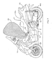
- Fig. 1 is a side view of a scooter-type motorcycle.
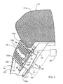
- Fig. 2 is an enlarged vertical cross sectional view of
the portion indicated by an
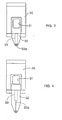
arrow 2 in Fig. 1. - Fig. 3 is a drawing of the portion indicated by an arrow 3 in Fig. 2 in a state in which the shutter is in the closed position.
- Fig. 4 is a drawing corresponding to Fig. 3, in a state in which the shutter is in the opened position.
- Fig. 5 is a drawing showing change of the pressure in the airbag after it is inflated.
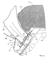
- Fig. 6 is a vertical cross sectional view corresponding to Fig. 2 in a state in which the airbag is inflated.
- Fig. 7 is a side view corresponding to Fig. 1 in a state in which the airbag is inflated.
- Fig. 8 is a drawing corresponding to Fig. 6 in a state in which the shutter is opened.
-
- Fig. 1 to Fig. 8 show an embodiment of the present invention.
- In Fig. 1, a front fork 7 is steerably supported on a
head pipe 6 provided at the front end of a vehicle body frame 5 of the scooter-type motorcycle, a front wheel WF is rotatably supported at the lower end of the front fork 7, and asteering handle 8 is connected to the upper portion of the front fork 7. Anengine unit 9 is supported for a vertical swinging motion at the rear portion of the vehicle body frame 5, atransmission case 11 of atransmission 10 for shifting and transmitting a power from theengine unit 9 to a rear wheel WR extends rearward from theengine unit 9 and the rear wheel WR is rotatably supported at the rear portion of thetransmission case 11. Arear cushion unit 13 is provided between aseat rail 12 provided at the rear potion of the vehicle body frame 5 and the rear end of theaforementioned mission case 11. - The vehicle body frame 5 is covered by a
vehicle body cover 14 formed of synthetic resin, and thevehicle body cover 14 includes afront cover 15 for covering the front portion of thehead pipe 6 and the upper portion of a front wheel WF, a pair of left andright leg shields 16... joined to both left and right sides of thefront cover 15 for covering forwardly of the occupant's legs, a pair of left and rightfoot rest portions 17... continuing from theleg shields 16... for supporting the feet of the occupant, afloor tunnel portion 18 rising upwardly at the portion between thefoot rest portions 17..., skirtportions 19 extending downward from the outer edges of both of the aforementionedfoot rest portions 17... respectively, and arear cover 20 covering the left and right sides of the rear portion of the vehicle body frame 5 and joined to thefoot rest portions 17... and thefloor tunnel portion 18. - A
tandem seat 21 having afront seat portion 21a on which the operator sits and arear seat portion 21b disposed rearwardly of thefront seat portion 21a so that a fellow passenger can sit thereon is provided on therear cover 20. - Referring also to Fig. 2, a supporting
stay 23 is secured to aseat rail 12 of the vehicle body frame 5 at the position downwardly of the front portion of theseat 21, and anairbag module 24 of the airbag apparatus is mounted on the supportingstay 23. - The
airbag module 24 includes anairbag housing 25, anairbag 26 to be stored in theairbag housing 25, and aninflator 27 for generating gas for inflating theairbag 26. - The
airbag housing 25 to be mounted to the supportingstay 23 facing toward an opening formed on therear cover 20 below the front portion of theseat 21, including acylindrical storage portion 25a in which theairbag 26 can be stored in the folded state and alid portion 25b for covering an upper end opening of thecylindrical storage portion 25a, is formed of light weight material such as synthetic resin into the cap shape and mounted to the supportingstay 23 by amounting strip 28 for attaching a lower end opening of thecylindrical storage portion 25a to the supportingstay 23. Thelid portion 25b is connected to thecylindrical storage portion 25a via a hingedportion 25c to be disposed at a position on the periphery of thelid portion 25b, for example, a position opposite from theseat 21, and a weakenedportion 25d to be disposed at the portion of the periphery of thelid portion 25b other than the hingedportion 25c, and the weakenedportion 25d is formed so as to be broken easily. - The
airbag 26 is formed like a bag having an opening 26a on the lower surface thereof and is stored in theairbag housing 25 in the folded state. Theinflator 27 is supported by amouth ring 29 to be secured to the opening 26a on the lower surface of theairbag 26, and themouth ring 29 is fixedly supported by theaforementioned mounting strip 28. - The vehicle body frame 5 is provided with an impact detection sensor (not shown) such as an acceleration sensor and the like, and the
aforementioned inflator 27 is actuated in response to the impact detection sensor upon detection of an impact larger than a predetermined value, and supplies high pressure gas into theairbag 26. - The
aforementioned mounting strip 28 is fixed with acase 30, which is formed of rigid material into a bottomed cylindrical shape, and be connected hermetically to the lower end opening 26a of theairbag 26, and anair discharge port 31, for example, of a square shape is formed at the closed end of thecase 30. - A
shutter 32 is mounted to the outer surface of the closed end of thecase 30 so as to be capable of a sliding motion between a closed position in which theair discharge port 31 is closed and an opened position in which theair discharge port 31 is opened as shown in Fig. 3, and a shutter-drivinginflator 33, which is fixedly supported by theaforementioned case 30, is connected to theshutter 32. - The shutter-driving
inflator 33 includes arod 33a to be actuated by gas generated when the inflator is actuated and projected therefrom, and therod 33a is connected to theaforementioned shutter 32 in such a manner that theaforementioned shutter 32 is moved instantaneously from the closed position to the opened position in response to actuation of the device for holding theshutter 32 at the closed position when it is not in operation. - Actuation, that is, ignition of the shutter-driving
inflator 33 is controlled by acontrol unit 34, and thecontrol unit 34 controls actuation of the shutter-drivinginflator 33 based on a detected value of apressure sensor 35 mounted to themouth ring 29 so as to detect the pressure in theairbag 26. - In this manner, the
control unit 34 controls actuation of the shutter-drivinginflator 33 in such a manner that the shutter-drivinginflator 33 is actuated at the timing t1 when the detected value of thepressure sensor 35, in other words, the pressure in theairbag 26 starts to be lowered after it is increased once, as shown by a solid line in Fig. 5. - The operation of the present embodiment will be described. The
air discharge port 31 and theshutter 32 that is capable of opening and closing theair discharge port 31 is mounted on the case to be hermetically connected to the lower opening 26a of theairbag 26. Theshutter 32 is connected with the shutter-drivinginflator 33 for closing theair discharge port 31 when it is not in operation, and is driven to open theair discharge port 31 by thecontrol unit 34 by actuating the shutter-drivinginflator 33 in response to lowering of the detected value of thepressure sensor 35 for detecting the pressure in theairbag 26 after it is increased once. - In other words, the
air discharge port 31 is closed in the normal state, and when an impact of more than a predetermined value is detected by the impact detection sensor due to collision or the like under such condition, theinflator 27 is actuated and feeds high-pressure gas into theairbag 26. Theairbag 26 breaks the weakenedportion 25d of theairbag housing 25 and instantaneously expands upwardly while opening thelid portion 25b by breaking the weakenedportion 25d of theairbag housing 25 as shown in Fig. 6 and Fig. 7. Accordingly, the operator sitting on thefront seat portion 21a of theseat 21 may be restrained by the inflated and deployedairbag 26 from the front. - When the pressure in the
airbag 26 is changed from the increasing state to the lowering state after the operator is decelerated by the inflated and deployedairbag 26, as shown in Fig. 8, the shutter-drivinginflator 33 is actuated and theshutter 32 moves instantaneously to the opened position where theair discharge port 31 is opened, thereby abruptly decreasing the pressure in theairbag 26. In this manner, the speed of response of air discharge from theairbag 26 may be enhanced sufficiently by adapting theshutter 32 to be opened quickly at the timing when theshutter 32 should be opened by making theshutter 32 move to the opened position by the shutter-drivinginflator 33. - In other words, the internal pressure of the
airbag 26 is increased to the value that is sufficient for effectively restrain and decelerate the operator and then lowered quickly, and thus bouncing phenomenon of the operator that may occur after the internal pressure in theairbag 26 reached the maximum value, that is, a phenomenon to accelerate the operator in the opposite direction may be prevented from occurring, and consequently, secondary impact to the operator due to the bounding phenomenon may be prevented from occurring. - Although the internal pressure in the
airbag 26 is lowered by discharging air from the airbag disclosed in the aforementioned publication of JP-A-2-216343, this device is adapted to hold back the maximum reaction force while obtaining more desirable reaction force depending on the conditions of collision or physical construction of the operator by lowering the pressure shown by a chain line in Fig. 5 to the pressure represented by a broken line in Fig. 5, but it is not intended to cope with the bouncing phenomenon that may occur after reaching the maximum internal pressure. - In contrast to it, the invention prevents occurrence of the bouncing phenomenon of the operator by discharging air quickly from the
airbag 26 in response to lowering of the pressure after the pressure in theairbag 26 reached the maximum pressure as described above. In addition, since air is discharged form theairbag 26 quickly in response to lowering of the pressure after the pressure in theairbag 26 reaches the maximum pressure irrespective of increasing speed of the pressure in theairbag 26, occurrence of the bouncing phenomenon may be prevented irrespective of the conditions of collision. - For example, in the aforementioned embodiment, the case in which the present invention is applied to a scooter-type motorcycle has been described. However, the present invention is applicable to four-wheeled passenger cars as well as small vehicles such as motorcycles other than scooter-type motorcycles and three-wheeled motorcycles
- In an on-vehicle airbag apparatus including an airbag housing having a breakably weakened portion, an airbag to be stored in the folded state in the aforementioned airbag housing so that the aforementioned weakened portion is broken upon inflation, and an inflator for generating gas for inflating the airbag, the speed of response of air discharge from the airbag is sufficiently enhanced.
Ashutter 32 that can open and close theair discharge port 31 is mounted on acase 30. Thecase 30, being formed of rigid material, is hermetically connected to an opening 26a of theairbag 26 and is provided with theair discharge port 31. A shutter-drivinginflator 33 for driving ashutter 32 from the closed position to the opened position when in operation is connected to theshutter 32.
Claims (2)
- An on-vehicle airbag apparatus comprising an airbag housing (25) having a breakably weakened portion (25d), an airbag (26) to be stored in the folded state in said airbag housing (25) so that said weakened portion (25d) is broken upon inflation, and an inflator (27) for generating gas for inflating the airbag (26), characterized in that the on-vehicle airbag apparatus further comprises a case (30) formed of rigid material hermetically connected to an opening (26a) of said airbag (26) and provided with an air discharge port (31), a shutter (32) mounted on said case (30) so as to be capable of moving between the closed position in which said air discharge port (31) is closed and the opened position in which said air discharge port (31) is opened, and a shutter-driving inflator (33) connected to said shutter (32) so as to hold said shutter (32) at the closed position when it is not in use and driving said shutter (32) instantaneously from the closed position to the opened position upon actuation.
- An on-vehicle airbag apparatus according to Claim 1, further comprising an pressure sensor (35) for detecting the pressure in said airbag (26), and a control unit (34) for controlling operation of the shutter-driving inflator (33) so as to actuate said shutter-driving inflator (33) for driving said shutter upon initiation of lowering of the detected value detected by the pressure sensor (35) after it has increased once.
Applications Claiming Priority (2)
| Application Number | Priority Date | Filing Date | Title |
|---|---|---|---|
| JP2002085679 | 2002-03-26 | ||
| JP2002085679A JP3901557B2 (en) | 2002-03-26 | 2002-03-26 | Airbag device for vehicle |
Publications (4)
| Publication Number | Publication Date |
|---|---|
| EP1348615A2 true EP1348615A2 (en) | 2003-10-01 |
| EP1348615A3 EP1348615A3 (en) | 2004-03-17 |
| EP1348615B1 EP1348615B1 (en) | 2008-03-05 |
| EP1348615B8 EP1348615B8 (en) | 2008-07-02 |
Family
ID=27800430
Family Applications (1)
| Application Number | Title | Priority Date | Filing Date |
|---|---|---|---|
| EP03005952A Expired - Fee Related EP1348615B8 (en) | 2002-03-26 | 2003-03-17 | On-vehicle airbag apparatus |
Country Status (6)
| Country | Link |
|---|---|
| US (1) | US7083187B2 (en) |
| EP (1) | EP1348615B8 (en) |
| JP (1) | JP3901557B2 (en) |
| CN (1) | CN1210176C (en) |
| DE (1) | DE60319453T2 (en) |
| ES (1) | ES2302522T3 (en) |
Families Citing this family (13)
| Publication number | Priority date | Publication date | Assignee | Title |
|---|---|---|---|---|
| JP2003327183A (en) * | 2002-05-15 | 2003-11-19 | Takata Corp | Air bag device for motorcycle, manufacturing method of air bag device for motorcycle and motorcycle with air bag device |
| DE202004015166U1 (en) * | 2004-09-29 | 2005-02-10 | Trw Automotive Safety Systems Gmbh | Airbag module |
| JP4645280B2 (en) * | 2005-04-18 | 2011-03-09 | 日産自動車株式会社 | Occupant protection device and method |
| JP4609941B2 (en) | 2005-09-07 | 2011-01-12 | 本田技研工業株式会社 | Airbag module mounting structure |
| US7556283B2 (en) | 2005-09-07 | 2009-07-07 | Honda Motor Co., Ltd. | Air bag module mounting structure |
| US7789416B2 (en) * | 2005-09-08 | 2010-09-07 | Honda Motor Co., Ltd. | Air bag module cover structure |
| JP4516595B2 (en) * | 2007-12-27 | 2010-08-04 | 本田技研工業株式会社 | Low floor vehicle |
| JP5140479B2 (en) * | 2008-04-02 | 2013-02-06 | タカタ株式会社 | Airbag device, motorcycle with airbag device |
| JP5222219B2 (en) * | 2009-04-28 | 2013-06-26 | 本田技研工業株式会社 | Saddle riding vehicle |
| JP2011073633A (en) * | 2009-09-30 | 2011-04-14 | Honda Motor Co Ltd | Airbag device of saddle-riding type vehicle |
| WO2018221179A1 (en) * | 2017-06-02 | 2018-12-06 | 本田技研工業株式会社 | Airbag device for saddle-type vehicle |
| SE1750845A1 (en) * | 2017-06-29 | 2018-12-30 | Hoevding Sverige Ab | Imroved airbag system |
| JP7075502B2 (en) * | 2018-11-14 | 2022-05-25 | 本田技研工業株式会社 | Saddle-type vehicle |
Citations (1)
| Publication number | Priority date | Publication date | Assignee | Title |
|---|---|---|---|---|
| JPH02216343A (en) | 1989-02-17 | 1990-08-29 | Nissan Motor Co Ltd | Air bag device |
Family Cites Families (22)
| Publication number | Priority date | Publication date | Assignee | Title |
|---|---|---|---|---|
| GB2130150B (en) * | 1982-11-11 | 1986-08-06 | Transport The Minister Of | Vehicle safety system |
| US5184845A (en) * | 1988-05-20 | 1993-02-09 | Nissan Motor Co., Ltd. | Air-bag system |
| JP3685872B2 (en) * | 1996-06-11 | 2005-08-24 | 本田技研工業株式会社 | Pressure adjusting device for air bag in motorcycle |
| US5853192A (en) * | 1996-10-10 | 1998-12-29 | Alliedsignal Inc. | Variable vented housing |
| US6039346A (en) * | 1997-01-17 | 2000-03-21 | General Motors Corporation | Air bag module with variable inflation |
| US5918901A (en) * | 1997-02-18 | 1999-07-06 | Autoliv Asp, Inc. | Airbag module with pressure relief adaptive performance |
| US6241279B1 (en) * | 1998-05-26 | 2001-06-05 | Honda Giken Kogyo Kabushiki Kaisha | Air bag device |
| JP3660129B2 (en) * | 1998-05-26 | 2005-06-15 | 本田技研工業株式会社 | Airbag device |
| US6669231B2 (en) * | 1998-11-04 | 2003-12-30 | Delphi Technologies, Inc. | Adaptive venting for an air bag module |
| US6213502B1 (en) * | 1998-11-24 | 2001-04-10 | Delphi Technologies, Inc. | Air bag module with variable inflation |
| DE29907607U1 (en) * | 1999-04-29 | 1999-09-30 | Trw Repa Gmbh | Protection device with gas bag for motor vehicle occupants |
| US6439603B2 (en) * | 1999-10-13 | 2002-08-27 | Delphi Technologies, Inc. | Air bag module with variable inflation |
| DE19958572C1 (en) * | 1999-12-04 | 2001-01-11 | Leica Camera Ag | Switched valve plate e.g. for automobile airbag, has rib attached to valve plate deformed by exerted pressure for release from stop edge to allow valve plate to pivot into open position |
| US6371517B1 (en) * | 1999-12-28 | 2002-04-16 | Delphi Technologies, Inc. | Adaptive inflation mechanism |
| US6547274B2 (en) * | 2000-02-07 | 2003-04-15 | Honda Giken Kogyo Kabushiki Kaisha | Air bag device |
| FR2811624B1 (en) * | 2000-07-12 | 2002-12-06 | Alstom | EXHAUST DEVICE FOR AN INFLATABLE ELEMENT AND DEVICE FOR PROTECTING A VEHICLE AGAINST IMPACT EQUIPPED WITH SUCH AN EXHAUST DEVICE |
| US6550807B1 (en) * | 2000-11-21 | 2003-04-22 | Trw Vehicle Safety Systems Inc. | Air bag module with electronically modulated vent |
| US6588795B2 (en) * | 2001-01-10 | 2003-07-08 | Trw Vehicle Safety Systems Inc. | Air bag module with vent |
| US6513835B2 (en) * | 2001-03-26 | 2003-02-04 | General Motors Corporation | Automotive vehicle air bag system |
| US6648371B2 (en) * | 2001-07-12 | 2003-11-18 | Delphi Technologies, Inc. | Variable venting air bag assembly |
| US20030107207A1 (en) * | 2001-10-12 | 2003-06-12 | Trw Inc. | Air bag module with vent cover |
| US6746044B2 (en) * | 2001-12-27 | 2004-06-08 | Trw Inc. | Actuatable fastener for air bag module vent |
-
2002
- 2002-03-26 JP JP2002085679A patent/JP3901557B2/en not_active Expired - Fee Related
-
2003
- 2003-03-17 ES ES03005952T patent/ES2302522T3/en not_active Expired - Lifetime
- 2003-03-17 DE DE60319453T patent/DE60319453T2/en not_active Expired - Lifetime
- 2003-03-17 EP EP03005952A patent/EP1348615B8/en not_active Expired - Fee Related
- 2003-03-20 CN CNB03120824XA patent/CN1210176C/en not_active Expired - Fee Related
- 2003-03-21 US US10/392,817 patent/US7083187B2/en not_active Expired - Fee Related
Patent Citations (1)
| Publication number | Priority date | Publication date | Assignee | Title |
|---|---|---|---|---|
| JPH02216343A (en) | 1989-02-17 | 1990-08-29 | Nissan Motor Co Ltd | Air bag device |
Also Published As
| Publication number | Publication date |
|---|---|
| DE60319453T2 (en) | 2009-03-26 |
| DE60319453D1 (en) | 2008-04-17 |
| ES2302522T3 (en) | 2008-07-16 |
| US20030222439A1 (en) | 2003-12-04 |
| CN1210176C (en) | 2005-07-13 |
| CN1446717A (en) | 2003-10-08 |
| JP2003276553A (en) | 2003-10-02 |
| JP3901557B2 (en) | 2007-04-04 |
| US7083187B2 (en) | 2006-08-01 |
| EP1348615B8 (en) | 2008-07-02 |
| EP1348615B1 (en) | 2008-03-05 |
| EP1348615A3 (en) | 2004-03-17 |
Similar Documents
| Publication | Publication Date | Title |
|---|---|---|
| JP4226259B2 (en) | Airbag device for small vehicles | |
| US7048299B2 (en) | Air bag apparatus for a scooter type motorcycle | |
| EP1348615B1 (en) | On-vehicle airbag apparatus | |
| JP3685873B2 (en) | Airbag device for motorcycle | |
| US7600777B2 (en) | Side airbag apparatus | |
| JP4357789B2 (en) | Motorcycle | |
| GB2306409A (en) | Airbag vent valves opened by a command signal | |
| US7390014B2 (en) | Protecting device for a pedestrian or the like | |
| WO2010147186A1 (en) | Airbag device for straddle type vehicles | |
| JP4129136B2 (en) | Motorcycle | |
| JPWO2018221178A1 (en) | Airbag device for saddle type vehicles | |
| JP2003285787A (en) | Air bag device | |
| JP6736769B2 (en) | Airbag device for saddle type vehicles | |
| JP4337516B2 (en) | Motorcycle with airbag device | |
| JP4129138B2 (en) | Airbag device for motorcycle | |
| JP5399139B2 (en) | Airbag device for saddle riding type vehicle | |
| JP4334853B2 (en) | Airbag device | |
| JP4339549B2 (en) | Airbag device | |
| JP3664878B2 (en) | Car occupant holding device | |
| US20220097643A1 (en) | Airbag module for a vehicle occupant restraint system, and method for operating a vehicle occupant restraint system comprising such an airbag module | |
| JP3739309B2 (en) | Airbag device for motorcycle | |
| CN115397724B (en) | Saddle-type vehicle | |
| JP2024013069A (en) | Airbag device of vehicle, airbag device of saddle riding vehicle, and airbag device of standing ride vehicle | |
| GB2377630A (en) | Vehicle seat safety arrangement | |
| JP2004224078A (en) | Riding person protection device for vehicle |
Legal Events
| Date | Code | Title | Description |
|---|---|---|---|
| PUAI | Public reference made under article 153(3) epc to a published international application that has entered the european phase |
Free format text: ORIGINAL CODE: 0009012 |
|
| AK | Designated contracting states |
Kind code of ref document: A2 Designated state(s): AT BE BG CH CY CZ DE DK EE ES FI FR GB GR HU IE IT LI LU MC NL PT RO SE SI SK TR |
|
| AX | Request for extension of the european patent |
Extension state: AL LT LV MK |
|
| PUAL | Search report despatched |
Free format text: ORIGINAL CODE: 0009013 |
|
| AK | Designated contracting states |
Kind code of ref document: A3 Designated state(s): AT BE BG CH CY CZ DE DK EE ES FI FR GB GR HU IE IT LI LU MC NL PT RO SE SI SK TR |
|
| AX | Request for extension of the european patent |
Extension state: AL LT LV MK |
|
| RIC1 | Information provided on ipc code assigned before grant |
Ipc: 7B 60R 21/28 B Ipc: 7B 62J 27/00 A |
|
| 17P | Request for examination filed |
Effective date: 20040427 |
|
| AKX | Designation fees paid |
Designated state(s): DE ES IT |
|
| 17Q | First examination report despatched |
Effective date: 20041229 |
|
| GRAP | Despatch of communication of intention to grant a patent |
Free format text: ORIGINAL CODE: EPIDOSNIGR1 |
|
| RIC1 | Information provided on ipc code assigned before grant |
Ipc: B60R 21/276 20060101AFI20071026BHEP |
|
| GRAS | Grant fee paid |
Free format text: ORIGINAL CODE: EPIDOSNIGR3 |
|
| GRAA | (expected) grant |
Free format text: ORIGINAL CODE: 0009210 |
|
| AK | Designated contracting states |
Kind code of ref document: B1 Designated state(s): DE ES IT |
|
| REF | Corresponds to: |
Ref document number: 60319453 Country of ref document: DE Date of ref document: 20080417 Kind code of ref document: P |
|
| RIN2 | Information on inventor provided after grant (corrected) |
Inventor name: AKIYAMA, HIDEKI,K. K. HONDA GIJUTSU KENKYUSHO Inventor name: YAMAMOTO, TAKENORI,K. K. HONDA GIJUTSU KENKYUSHO Inventor name: IIJIMA, SATOSHI,K. K. HONDA GIJUTSU KENKYUSHO. |
|
| REG | Reference to a national code |
Ref country code: ES Ref legal event code: FG2A Ref document number: 2302522 Country of ref document: ES Kind code of ref document: T3 |
|
| PLBE | No opposition filed within time limit |
Free format text: ORIGINAL CODE: 0009261 |
|
| STAA | Information on the status of an ep patent application or granted ep patent |
Free format text: STATUS: NO OPPOSITION FILED WITHIN TIME LIMIT |
|
| 26N | No opposition filed |
Effective date: 20081208 |
|
| REG | Reference to a national code |
Ref country code: DE Ref legal event code: R084 Ref document number: 60319453 Country of ref document: DE Effective date: 20111128 |
|
| PGFP | Annual fee paid to national office [announced via postgrant information from national office to epo] |
Ref country code: IT Payment date: 20120320 Year of fee payment: 10 |
|
| PGFP | Annual fee paid to national office [announced via postgrant information from national office to epo] |
Ref country code: DE Payment date: 20120411 Year of fee payment: 10 |
|
| PGFP | Annual fee paid to national office [announced via postgrant information from national office to epo] |
Ref country code: ES Payment date: 20120419 Year of fee payment: 10 |
|
| REG | Reference to a national code |
Ref country code: DE Ref legal event code: R119 Ref document number: 60319453 Country of ref document: DE Effective date: 20131001 |
|
| PG25 | Lapsed in a contracting state [announced via postgrant information from national office to epo] |
Ref country code: DE Free format text: LAPSE BECAUSE OF NON-PAYMENT OF DUE FEES Effective date: 20131001 |
|
| PG25 | Lapsed in a contracting state [announced via postgrant information from national office to epo] |
Ref country code: IT Free format text: LAPSE BECAUSE OF NON-PAYMENT OF DUE FEES Effective date: 20130317 |
|
| REG | Reference to a national code |
Ref country code: ES Ref legal event code: FD2A Effective date: 20140715 |
|
| PG25 | Lapsed in a contracting state [announced via postgrant information from national office to epo] |
Ref country code: ES Free format text: LAPSE BECAUSE OF NON-PAYMENT OF DUE FEES Effective date: 20130318 |