FIELD OF THE INVENTION
The present invention relates to apparatus and methods for printing
and in particular to drop-on-demand (DOD) inkjet printing methods
and apparatus.
BACKGROUND OF THE INVENTION
When DOD inkjet is considered, two main groups can be discerned:
thermal inkjet and piezo inkjet.
With thermal inkjet technology, tiny resistors rapidly heat a thin
layer of liquid ink. The heated ink causes a vapour bubble to be
formed, expelling or ejecting drops of ink through nozzles and
placing them precisely on a surface to form text or images. As the
bubble collapses, it creates a vacuum that pulls in fresh ink. This
process is repeated thousands of times per second. With thermal
inkjet technology, water-based inks are used.
Piezoelectric printing technology - commonly called piezo - pumps
ink through nozzles using pressure, like a squirt gun. A piezo
crystal used as a very precise pump places ink onto the printing
medium. A wide range of ink formulations (solvent, water, UV) may be
used.
A number of different piezo concepts exist.
A typical concept, as described in US-4887100, WO 96/10488, WO
97/04963 and WO 99/12738, uses so called shared walls. The pressure
chambers containing the ink are next to each other, while their
dividing walls are the actuators.
Because an actuator is always shared by two channels, it is not
possible to jet a drop out of two neighbouring channels at the same
time. In WO 96/10488 is described that the nozzles are divided in
three interlaced groups (A, B, C). Neighbouring nozzles are fired in
a sequence ABC. Two solutions are possible to print dots on a
straight line.
A first solution uses a complete nozzle array under a certain angle.
By doing this, the resolution is increased, and by using the right
fast scan speed, dots fired in a sequence A, B, C are on a straight
line.
A second solution uses a head perpendicular to the fast scan
direction, in which the A, B, and C nozzles are staggered in the
fast scan direction. Printing of a line of pixels is divided into
three cycles. In the first cycle, the dividing walls to either side
of the A channels are driven (if ink is to be ejected from them -
depending on the image to be printed) with a pulsed signal. In the
second cycle, the dividing walls to either side of the B channels
are driven (if ink is to be ejected from them - depending on the
image to be printed) with a pulsed signal. In the third cycle, the
dividing walls to either side of the C channels are driven (if ink
is to be ejected from them - depending on the image to be printed)
with a pulsed signal. The pressure pulses developed in the channels
that are not included in the current cycle are not larger than 1/2
of those in the channels that are intended to eject ink. The
printing apparatus is arranged so that such pulses with 1/2
magnitude do not cause ink ejection.
A drawback of this concept is that, once the firing frequency is
defined, only one fast scan speed can be used to print ABC dots on a
straight line, as explained hereinafter. In the fast scan direction,
the head will e.g. print each 1/360-inch.
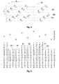
Fig. 1 shows a piezo printhead 10 according to the prior art, having
nozzles 12 which are divided into three sets, called a set of A
nozzles, a set of B nozzles and a set of C nozzles, each set
intended to be fired during different firing cycles. The different
sets of nozzles are staggered with respect to each other over a
stagger distance D1 in the fast scan direction. If the nozzles are
divided in groups G of three, every first nozzle is part of the set
of A nozzles, every second nozzle is part of the set of B nozzles
and every third nozzle is part of the set of C nozzles. All nozzles
in one set A, B, C are positioned on a straight line in the slow
scan direction S, which lines are located at the stagger distance D1
with respect to each other in the fast scan direction F.
As an example, printhead 10 is considered to be a type 360 head.
This means that the printhead 10 is provided for printing 360 dpi (=
pixels per inch) in the fast scan direction F. In this type 360
printhead 10, the distance D1 between nozzles 12 in the fast scan
direction F is 1/360 inch / 3 = 70.56 µm / 3 = 23.52 µm.
If the firing frequency is 12.4 kHz, meaning that every set A, B, C
of nozzles can be fired every 80.65 µs, the speed of the printhead
10 in the fast scan direction F is 1/360 inch * 12.4 kHz = 0.875
m/s. The nozzles 12 are fired in an ABC sequence, with the A nozzles
at the leading edge of the printhead 10 in the fast scan direction
F.
The cycle frequency is 12.4 kHz * 3 = 37.2 kHz. Or formulated in
another way: the set of B nozzles fires 26.88 µs after the set of A
nozzles, and the set of C nozzles fires 53.76 µs after the set of A
nozzles. After 80.65 µs, the set of A nozzles fires again.
One type of printing may be called "mutually interstitial printing",
also called shingling e.g. as in US-4,967,203, in which adjacent
pixels on a raster line in the fast scan direction are not printed
by the same nozzle in the printhead. Printing dictionaries, however,
refer to "shingling" as a method to compensate for creep in book-making.
The inventors are not aware of any industrially accepted
term for the printing method wherein no adjacent pixels on a raster
line are printed by one and the same nozzle. Therefore, from here on
and in what follows, the terms "mutually interstitial printing" or
"interstitial mutually interspersed printing" are used. It is meant
by these terms that an image to be printed is split up in a set of
sub-images, each sub-image comprising printed parts and spaces, and
wherein at least a part of the spaces in one printed sub-image form
a location for the printed parts of another sub-image, and vice
versa.
When it would be desired to keep the same firing frequency, but to
print a 180 * 180 dpi image with the 360 type printhead of the
example given above, the printhead speed should theoretically double
to 1.750 m/s. In the above case of printing a 180 * 180 dpi image
with a 360 type printhead, where the printhead speed must double to
1.750 m/s, the delays for firing B and C need to be shorter to make
sure that dots are printed on the same line. Nozzle set B has to be
fired 13.44 µs after nozzle set A, and nozzle set C 26.88 µs after
nozzle set A. These firing frequencies are too close one to the
other, and therefore a 360 type printhead cannot be used to print a
180 * 180 dpi image.
When it would be desired, on the other hand, to print a 720 * 720
dpi image with the 360 type printhead, the firing delay between the
set of A nozzles, set of B nozzles and set of C nozzles increases to
53.76 µs. As, however, after 80.65 µs the set of A nozzles has to
fire again, there is not enough time left to fire the set of C
nozzles, and therefore a 360 type printhead cannot be used to print
a 720 * 720 dpi image neither.
It is an object of the present invention to provide a method for
printing, with one type of printhead, with a resolution which
differs from the design resolution of the type of printhead used.
SUMMARY OF THE INVENTION
The above objective is accomplished by a method of driving a print
head according to the present invention. A print head used has a
longitudinal axis in a slow scan direction and has an array of
marking elements comprising at least one group of marking elements.
Marking elements of one group are staggered with respect to each
other over a stagger distance in a fast scan direction, which is
perpendicular to the slow scan direction. The print head is intended
to be driven with a reference velocity Vref, which is equal to the
stagger distance, multiplied by a reference firing frequency Fref.
One marking element of a group is able to be fired at each reference
firing frequency pulse (whether it fires depends upon the image to
be printed). The marking elements of the print head are intended to
be fired according to a reference firing order to print an image
with a first resolution. The method of the present invention is
characterised in that it is operated at an operating velocity that
is different from the reference velocity so as to print the same
image with a different resolution.
If there are n marking elements in one group, wherein the
operating velocity may be equal to reference velocity / nX+1 or to
reference velocity / nX-1, X being an integer larger than 0. In the first case,
the firing order of the marking elements equals the reference firing
order, in the second case it equals the inverse of the reference
firing order.
The above methods may be used for carrying out fast mutually
interstitial printing.
The present invention also includes a printing device with a
print head (10) having a longitudinal axis in a first direction (S)
and having an array of marking elements (A, B, C; A, B, C, D)
comprising at least one group (G) of marking elements (A, B, C; A,
B, C, D), marking elements (A, B, C; A, B, C, D) of one group (G)
being staggered with respect to each other over a stagger distance
(D1) in a second direction (F) perpendicular to the first direction
(S), the print head (10) being intended to be driven with a
reference velocity (Vref) equal to the stagger distance (D1)
multiplied by a reference firing frequency (Fref), one marking
element of a group being firable at each reference firing frequency
pulse, the marking elements (A, B, C; A, B, C, D) of the print head
(10) being intended to be fired according to a reference firing
order to print an image at a first resolution, further comprising
means for driving the print head (10) at an operating velocity which
is different from the reference velocity to print the same image at
a second resolution of printing. For this printing device there may
be n marking elements (A, B, C; A, B, C, D) in one group (G) and the
operating velocity for printing with the second resolution is equal
to reference velocity / nX+1, X being an integer larger than or equal to 0.,
the firing order of the marking elements (A, B, C; A, B, C, D) to
print the second resolution being the same as the reference firing
order (ABC; ABCD). Alternatively, this printing device has n marking
elements (A, B, C; A, B, C, D) in one group (G), wherein the
operating velocity to print the second resolution is equal to
reference velocity / nX-1, X being an integer larger than 0, the firing order
of the marking elements (A, B, C; A, B, C, D) to print the second
resolution equalling the inverse of the reference firing order (CBA;
DCBA).
For either of these arrangements the marking elements (A, B, C;
A, B, C, D) of one group (G) may be staggered with respect to each
other over a stagger distance (D1) in a second direction (F)
perpendicular to the first direction (S) to form a plurality of rows
of marking elements, and the printing device may be adapted to
supply printing data representing the image to the marking elements
of one row which is delayed with respect to the printing data
supplied to another row.
The present invention also includes a computer program product
for executing any of the methods of the present invention when
executed on a computing device associated with a printing head. A
machine readable data storage device may store the computer program
product. The computer program product may be transmitted over a
local or wide area telecommunications network.
The present invention also includes a control unit for a printer
for printing an image on a printing medium using a print head (10)
having a longitudinal axis in a first direction (S) and having an
array of marking elements (A, B, C; A, B, C, D) comprising at least
one group (G) of marking elements (A, B, C; A, B, C, D), marking
elements (A, B, C; A, B, C, D) of one group (G) being staggered with
respect to each other over a stagger distance (D1) in a second
direction (F) perpendicular to the first direction (S), the control
unit being adapted to control the driving of the print head (10)
with a reference velocity (Vref) equal to the stagger distance (D1)
multiplied by a reference firing frequency (Fref), and for
controlling the firing of one marking element of a group at each
reference firing frequency pulse, and for controlling the firing of
the marking elements (A, B, C; A, B, C, D) of the print head (10)
according to a reference firing order to print the image at a first
resolution, further comprising means for controlling the driving of
the print head (10) at an operating velocity which is different from
the reference velocity to print the image at a second resolution of
printing.
Although there has been constant improvement, change and
evolution of devices in this field, the present concepts are
believed to represent substantial new and novel improvements,
including departures from prior practices, resulting in the
provision of more efficient devices of this nature.
Other features and advantages of the present invention will
become apparent from the following detailed description, taken in
conjunction with the accompanying drawings, which illustrate, by way
of example, the principles of the invention. This detailed
description is given for the sake of example only, without limiting
the scope of the invention. The reference figures quoted below refer
to the attached drawings.
BRIEF DESCRIPTION OF THE DRAWINGS
- Fig. 1
- is a front view of a printhead with staggered marking
elements as known in the prior art.
- Fig. 2
- schematically illustrates an ABC printing scheme of a
printhead according to Fig. 1.
- Fig. 3
- is a front view of a printhead with two arrays of marking
elements, each having a first resolution, the nozzle arrays
being placed so that the combined resolution equals twice the
first resolution.
- Fig. 4
- schematically shows a printhead consisting of two staggered
nozzle arrays.
- Fig. 5
- is a printing scheme for 12.5% mutually interstitial printing
according to an embodiment of the present invention.
- Fig. 6
- schematically illustrates an ABCD printing scheme in
accordance with an embodiment of the present invention for a
printing head with four marking elements in one group.
- Fig. 7
- is a highly schematic representation of an inkjet printer for
use with the present invention.
- Fig. 8
- is a schematic representation of a printer controller in
accordance with an embodiment of the present invention.
DETAILED DESCRIPTION OF THE INVENTION
The present invention will be described with reference to
various embodiments and drawings but the present invention is not
limited thereto but only by the claims.
The term "printing" as used in this invention should be
construed broadly. It relates to forming markings whether by ink or
other materials or methods onto a printing substrate. Various
printing methods which may be used with the present invention are
described in the book "Principles of non-impact printing", J. L.
Johnson, Palatino Press, Irvine, 1998, e.g. thermal transfer
printing, thermal dye transfer printing, deflected ink jet printing,
ion projection printing, field control printing, impulse ink jet
printing, drop-on-demand ink jet printing, continuous ink jet
printing. Non-contact printing methods are particularly preferred.
However, the present invention is not limited thereto. Any form of
printing including dots or droplets on a substrate is included
within the scope of the present invention, e.g. piezoelectric
printing heads may be used to print polymer materials as used and
described by Plastic Logic (http://plasticlogic.com/) for the
printing of thin film transistors. Hence, the term "printing" in
accordance with the present invention not only includes marking with
conventional staining inks but also the formation of printed 2-D or
3-D structures or areas of different characteristics on a substrate.
On example is the printing of water repellent or water attractive
regions on a substrate in order to form an off-set printing plate by
printing. Accordingly, the term "printing medium" or "printing
substrate" should also be given a wide meaning including not only
paper, transparent sheets, textiles but also flat plates or curved
plates which may be included in or be part of a printing press. In
addition the printing may be carried out at room temperature or at
elevated temperature, e.g. to print a hot-melt adhesive the printing
head may be heated above the melting temperature. Accordingly, the
term "ink" should also be interpreted broadly including not only
conventional inks but also solid materials such as polymers which
may be printed in solution or by lowering their viscosity at high
temperatures as well as materials which provide some characteristic
to a printed substrate such as information defined by a structure on
the surface of the printing substrate, water repellence, or binding
molecules such as DNA which are spotted onto microarrays. As
solvents both water and organic solvents may be used. Inks as used
with the present invention may include a variety of additives such
as ant-oxidants, pigments and cross-linking agents.
In the following the invention will be described with respect
to one type of printing, e.g. ink jet printing in which a printhead
traverses with respect to a printing medium in a first direction
(fast scan direction) while the print medium indexes forwards
relative to the printhead in a direction perpendicular to this (slow
scan direction). In a method according to the present invention,
the speed in the fast scan direction is changed with reference to a
reference velocity which the printhead is intended to be driven
with, while preferably keeping the firing frequency of the sets of
nozzles unchanged. This is done in order to be able to print, with a
printhead of a certain type, which is intended to print images with
a certain resolution, images with other resolutions. If needed, the
firing sequence is changed as well.
FIRST EMBODIMENT: THREE MARKING ELEMENTS IN A GROUP
A printhead 10 used according to the first embodiment has three
sets of marking elements or nozzles 12: a set of A-nozzles, a set of
B-nozzles and a set of C-nozzles. This means that there a three
nozzles 12 in one group G, as represented in Fig. 1.
For a printhead 10 intended to print images of a certain basic
resolution, changing the firing sequence from ABC to CBA while using
half the fast scan speed used for the ABC sequence, makes it
possible to print images with a resolution which is the double of
the basic resolution. For example a type 360 head, with a stagger
distance D1 of 23.52 µm between two neighbouring sets of nozzles,
which head 10 is normally intended to be fired (in an ABC firing
sequence) at a frequency of 12.4 kHz and moved with a speed of 0.875
m/s, can be used for printing images with a resolution of 720 dpi by
using half the fast scan speed (i.e. 0.4375 m/s) and by firing the
nozzles in a sequence CBA.
If the example of the above type 360 head is worked out
further, the following is obtained. If the set of C nozzles is fired
first, the set of B nozzles is already 23.52 µm ahead in the fast
scan direction F. At a speed of 0.875 m/s (at a firing frequency of
12.4 kHz), the set of B nozzles would have travelled another 23.52
µm in the fast scan direction F before actually firing. When,
however, half the fast scan speed is used, the set of B nozzles will
only travel over 11.76 µm before it is fired, so that there is a
distance of 35.28 µm in the fast scan direction between the dots
printed by the set of C nozzles and the dots printed by the set of B
nozzles. This corresponds to the distance between dots in a 720 dpi
image.
With the CBA firing sequence, the dots printed by the sets of
A, B and C nozzles in one cycle are not printed on one straight
line, with a pitch of 1/360 inch between lines printed during
different cycles, but instead they are printed on three different
lines with a pitch of 1/720 inch between them.
Also other pitches or modes are possible with the same head
type at different fast scan speeds. The only difference with the
"standard pitch" is that the dots printed during one CBA cycle are
not on one straight line, contrary to the dots printed during one
normal ABC cycle. With a "normal ABC cycle" is meant: firing the
nozzles 12 in an ABC firing sequence, with a reference firing
frequency and driving the head 10 with a reference driving speed for
which the head 10 is intended.
In general, the following relationship between the speeds is
obtained:
Vmode =VFF c
with vmode the speed for the considered mode
vFF the reference speed for the head type for use with a
predetermined firing frequency FF. The speed VFF is given by (phi) ϕ
x nozzle stagger distance (DI) x the firing frequency where ϕ (phi)
is the number of staggered rows of nozzles.
mode = c * headtype expressed in dpi,
where,
in case c = 3 i + 1, with i = integer ≥ 0
the firing sequence is ABC
in case c = 3 i - 1, with i = integer > 0
the firing sequence is CBA
This means that, for the present embodiment it is impossible to
print in a mode that has a speed vmode, which e.g. equals one third
of the reference speed vFF for the head type (as c is either 3i +1
or 3i -1 and can never be a factor of 3). This also means that, for
this embodiment, it is impossible to print images with a resolution
that equals a plurality of three times the resolution of the head
used.
A more in depth analysis shows that a type 90 head offers
following possibilities:
| Head type | Nozzle stagger | Firing frequency | Desired image resolution in fast scan direction | Head speed | Cycling direction |
| 90 | 94.07 µm | 12400 Hz | 90 dpi | 3.50 m/s | ABC |
| 90 | 94.07 µm | 12400 Hz | 180 dpi | 1.75 m/s | CBA |
| 90 | 94.07 µm | 12400 Hz | 360 dpi | 0.87 m/s | ABC |
| 90 | 94.07 µm | 12400 Hz | 450 dpi | 0.70 m/s | CBA |
| 90 | 94.07 µm | 12400 Hz | 630 dpi | 0.50 m/s | ABC |
| 90 | 94.07 µm | 12400 Hz | 720 dpi | 0.44 m/s | CBA |
| 90 | 94.07 µm | 12400 Hz | 900 dpi | 0.35 m/s | ABC |
| 90 | 94.07 µm | 12400 Hz | 990 dpi | 0.32 m/s | CBA |
| 90 | 94.07 µm | 12400 Hz | 1170 dpi | 0.27 m/s | ABC |
| 90 | 94.07 µm | 12400 Hz | 1260 dpi | 0.25 m/s | CBA |
| 90 | 94.07 µm | 12400 Hz | 1440 dpi | 0.22 m/s | ABC |
As mentioned above, the pixels printed during one printing
cycle are not printed in one row. The distance between the pixels
printed by a B- or C-nozzle and an A-nozzle during the same cycle is
given by (expressed in 1/mode pitch):
pitch =1mode =1 c*headtype [inches]
According to the above, if nozzle A prints dots on an image
line during cycle x, the B nozzles will print during cycle
x+int(c/3) and the C nozzles during cycle x+int(2c/3) on the same
image line.
Thus for a type 90 head printing in 360 mode, c = 4 and
ΔcycleA-B = 1 and ΔcycleA-C = 2, so if nozzles A print dots on an
image line during cycle x, nozzles B print dots on that image line
during cycle x+1 and nozzles C print dots on that image line during
cycle x+2.
According to the above, if nozzle A prints dots on an image
line during cycle x, the B nozzles will print on the same image line
during cycle x+int(c/3)+1 and the C nozzles will print on the same
image line during cycle x+int(2c/3)+1.
Thus for a type 360 head printing in 720 mode, c = 2 and
ΔcycleB-A = 1 and ΔcycleC-A = 2, so if nozzles A print dots on an
image line during cycle x, nozzles B print dots on that image line
during cycle x+1 and nozzles C print dots on that image line during
cycle x+2.
Fig. 2 shows an ABC firing case at c = 7, e.g. a type 90 head
in 630 dpi mode. As shown in table 1, the normal speed or reference
speed for a 90 type head is 3.50 m/s. According to equation (1), the
speed in the 630 dpi mode is 3.50/7 = 0.50 m/s, as also shown in
Table 1. Equation (3) shows that for c = 7, the nozzles are to be
driven in an ABC sequence.
During a first cycle, the set of A nozzles is driven first.
Where necessary (according to the image) A nozzles eject a drop on
locations 14 on a straight line 16 in the slow scan direction S. At
the moment of firing the set of A nozzles, the set of B nozzles is
located at a location 18 at a distance of 1/(headtype.3) = 1/90.3
= 1/270 inches = 94.07 µm behind the set of A nozzles, and the set
of C nozzles is located at a location 20 at a distance of 188.15 µm
behind the set of A nozzles. Before firing the set of B nozzles, the
head 10 is moved over a distance 1/(c.headtype.3) = 1/1890 inches =
13.44 µm in the fast scan direction F. During the first cycle, the
set of B nozzles ejects a drop on locations 22 on a straight line 24
in the slow scan direction S, where necessary according to the image
to be printed. At the moment of firing the set of B nozzles, the set
of C nozzles is located at a location 26 at a distance of 94.07 µm
behind the set of B nozzles. Before firing the set of C nozzles, the
head 10 is moved over a distance 1/(c.headtype.3) = 1/1890 inches =
13.44 µm in the fast scan direction F. During the first cycle, the
set of C nozzles ejects a drop on locations 28 on a straight line 30
in the slow scan direction S, where necessary according to the image
to be printed.
At the moment of firing the set of C nozzles, the set of A
nozzles is located at a location 32 at a distance of 188.15 µm in
front of the set of C nozzles, and the set of B nozzles is located
at a location 34 at a distance of 94.07 µm behind the set of A (or
94.07 µm in front of the set of C nozzles). Before firing the set of
A nozzles during a second cycle, the head 10 is moved over a
distance of 13.44 µm in the fast scan direction F. During the second
cycle, the set of A nozzles eject a drop on locations 36 on a
straight line 38 in the slow scan direction S, where necessary
according to the image to be printed. At the moment of firing the
set of A nozzles, the set of B nozzles is located at a location 40
at a distance of 94.07 µm behind the set of A nozzles. Before firing
the set of B nozzles, the head 10 is moved over a distance of 13.44
µm in the fast scan direction F. The set of B nozzles eject a drop
on locations 42 on a straight line 43 in the slow scan direction S,
where necessary according to the image to be printed.
The above printing scheme is continued in the same way. In the
next (third) ABC cycle, the drops of the B nozzles are ejected on
locations on straight line 16, where necessary according to the
image to be printed, and the drops of the C nozzles are ejected on
locations on straight line 24, where necessary according to the
image to be printed.
This corresponds to what is given in equations (6): for c=7 and
ABC cycling,
Thus if the set of A nozzles prints on a straight line during cycle
x (e.g.
straight line 16 during cycle 1), the set of B nozzles will
print on that same straight line during cycle x+2 (
cycle 3 in the
example given), and the set of C nozzles will print on that same
straight line during cycle x+4 (
cycle 5 in the example given).
The printhead 10 continues to move on in the fast scan
direction F up to the end of the printing medium on which an image
is to be printed, according to the content of the image to be
printed. Dots are printed on straight lines 16, 24, 30, 38, 43 and
so on, in the slow scan direction S, each straight line comprising
dots printed by the set of A nozzles, the set of B nozzles and the
set of C nozzles, if necessary for the image to be printed. The
distance between two straight lines in the slow scan direction is
1/(c.headtype) = 1/(7.90) inches = 40.32 µm, which shows that an
image at 630 dpi is printed.
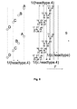
In Fig. 3, a nozzle plate 50 of two nozzle arrays 52, 54 is
shown, each nozzle array 52, 54 having 225 npi (nozzles per inch),
and placed so that the combined resolution is 450 dpi (i.e. whereby
each nozzle of the second nozzle array 54 is always located in the
middle, in the slow scan direction S, between two nozzles of the
first nozzle array 52). The distance between two adjacent nozzles of
one nozzle array in the slow scan direction S is 112.89 µm. The
nozzle stagger in the fast scan direction F is 94.07 µm (type 90
head).
As an example, the type 90 head is used in 450 dpi mode to
obtain an image with a resolution of 900 dpi in at least two passes.
A type 90 head used in mode 450 follows a CBA printing cycle, as
shown in Table 1.
During a first pass, at first during a first cycle, the sets of
C nozzles are fired. Where necessary (according to the image), C
nozzles eject a drop on the printing medium, whereby C nozzles of
the first nozzle array 52 eject drops on locations 62, and C nozzles
of the second nozzle array 54 eject drops on locations 64. At the
moment of firing the sets of C nozzles, the set of B nozzles of the
first array 52 is located at location 66 at a distance of
1/(headtype.3) = 94.07 µm before the set of C nozzles of the first
array 52, and the set of B nozzles of the second array 54 is located
at locations 68 at a distance of 94.07 µm before the set of C
nozzles of the second array 54. Before firing the sets of B nozzles,
the head 50 is moved over a distance 1/(c.headtype.3) = 18.81 µm in
the fast scan direction F. During the first cycle, the set of B
nozzles of the first nozzle array 52 ejects a drop on locations 70,
where necessary according to the image to be printed, and the set of
B nozzles in the second array 54 ejects a drop on locations 72,
where necessary according to the image to be printed. At the moment
of firing the sets of B nozzles, the set of A nozzles of the first
array 52 is located at a location 74 at a distance of 94.07 µm
before the set of B nozzles of the first array 52, and the set of A
nozzles of the second array 54 is located at a location 76 at a
distance of 94.07 µm before the set of B nozzles of the second array
54. Before firing the sets of A nozzles, the head 50 is moved over a
distance of 18.81 µm in the fast scan direction F. The set of A
nozzles of the first array 52 ejects a drop on locations 78, and the
set of A nozzles of the second array 54 ejects a drop on location
80, both where necessary according to the image to be printed.
When the sets of A nozzles are firing, the set of C nozzles of
the first array 52 is located at locations 82, and the set of C
nozzles of the second array 54 is located at locations 84. Before
firing the sets of C nozzles during the second cycle, the head 50 is
moved over a distance of 18.81 µm in the fast scan direction F. The
set of C nozzles of the first array 52 ejects a drop on locations
86, and the set of C nozzles of the second array 54 ejects a drop on
locations 88, both where necessary according to the image to be
printed.
At the moment of firing the sets of C nozzles, the set of B
nozzles of the first array 52 is located at location 90 at a
distance of 94.07 µm before the set of C nozzles of the first array
52, and the set of B nozzles of the second array 54 is located at
locations 92 at a distance of 94.07 µm before the set of C nozzles
of the second array 54. Before firing the sets of B nozzles during
the second cycle, the head 50 is moved over a distance of 18.81 µm
in the fast scan direction F. The set of B nozzles of the first
nozzle array 52 ejects a drop on locations 94, where necessary
according to the image to be printed, and the set of B nozzles in
the second array 54 ejects a drop on locations 96, where necessary
according to the image to be printed. At the moment of firing the
sets of B nozzles, the set of A nozzles of the first array 52 is
located at a location 98 at a distance of 94.07 µm before the set of
B nozzles of the first array 52, and the set of A nozzles of the
second array 54 is located at a location 100 at a distance of 94.07
µm before the set of B nozzles of the second array 54. Before firing
the sets of A nozzles during the second cycle, the head 50 is moved
over a distance of 18.81 µm in the fast scan direction F. During the
second printing cycle, the set of A nozzles of the first array 52
ejects a drop on locations 102, where necessary according to the
image to be printed, and the set of A nozzles of the second array 54
ejects a drop on location 104, where necessary according to the
image to be printed.
When the sets of A nozzles are firing, the set of C nozzles of
the first array 52 is located at locations 106, and the set of C
nozzles of the second array 54 is located at locations 108. Before
firing the sets of C nozzles during a third printing cycle, the head
50 is moved over a distance of 18.81 µm in the fast scan direction
F. The set of C nozzles of the first array 52 ejects a drop on
locations 110, where necessary according to the image to be printed,
and the set of C nozzles of the second array 54 ejects a drop on
locations 112, where necessary according to the image to be printed.
Drops printed by the set of C nozzles of the first array 52 on
locations 110 during the third printing cycle are printed on a
straight line 111, on which line 111 previously (during the first
printing cycle) drops 70 have been printed by the set of B nozzles
of the first array 52. In the same manner, drops printed by the set
of C nozzles of the second array 54 on locations 112 during the
third printing cycle are printed on a straight line 113, on which
line 113 previously (during the first printing cycle) drops 72 have
been printed by the set of B nozzles of the second array 54.
This printing scheme continues. The continuation of the
printing scheme is shown in Fig. 3 without further numbering of the
dots. As can be seen, as from straight line 114 in the slow scan
direction, drops are printed on locations 116 by the set of C
nozzles of the first array 52, while on that same straight line 114
drops 118, 120, 122, 80, 124 have already been printed previously by
the set of C nozzles of the second array 54, the set of B nozzles of
the second array 54, the set of B nozzles of the first array 52, the
set of A nozzles of the second array 54, and the set of A nozzles of
the first array 52, respectively.
Before starting a second pass, the printhead 50 is moved in the
slow scan direction S so as to make droplets fall in between already
printed droplets in the slow scan direction S. For the example under
consideration, if the resolution is to be obtained in two passes,
the printhead 50 is moved in the slow scan direction S over a paper
feed distance of 28.22 µm or an odd multiple thereof. During the
second and further printing passes, a CBA cycle is then applied as
explained for the first printing pass.
According to the above it is clear that it is only possible to
have dots from three phases printed during one cycle on one slow
scan line using a normal print order for the data if the print head
type and mode are equal. Otherwise the print data must be
reorganised or "shuffled" so that the correct data is presented to
the relevant nozzle at the right time.
The most convenient solution consists in shifting the pixel
lines along the fast scan direction (if different nozzle arrays are
combined resulting in pixel lines belonging to one phase one also
speaks of image bands) related to the different phases over a number
of cycles as given by formula 6 or 7. In case a 3 phase system with
phases ABC, the shift between pixel line A and B and between B and C
is equal to a number equal to the Δcycle as given by formula 6
(formula 7 in case a CBA cycle is involved). It is necessary to
reorganise the sequence of input data so that the final image is
correctly printed. When data for pixels on a certain slow scan line
is printed by the A phase, the data for the same slow scan line but
for the B-phase nozzles will be presented to them later. Another
Δcycle later the C-phase nozzles will receive the data related to
that slow scan line. When one cycle is considered, the B-phase
prints during that cycle a dot that is Δcycle dot positions behind
the A phase, while the C-phase is printing 2 Δcycle dot positions
behind the A phase. For example, 2 or 4 dot positions as defined in
equation 8. The data transformation needs to be done for each new
fast scan because it is possible that when using mutually
interstitial printing, nozzles belonging to different phases print a
certain pixel line in the fast direction.
This printing technique requires more pixel positions than the
number of pixel positions in a fast scan pixel line to finish a fast
scan than would be required if the nozzles were not staggered but on
a straight line.
It is now explained in more detail how paper feeds in between
successive printing passes are calculated and how wet-on-wet
printing or bleeding is avoided by enforcing boundary conditions on
the colour sequence.
The following is a general calculation scheme to obtain values
for a paper feed L1 and a paper feed L2, expressed in pixels (on the
final image resolution). It will be explained, based on a printhead
130 as shown in Fig. 4, having n=764 nozzles. The printhead itself
consists of 2 nozzle arrays 132, 134, each having 382 nozzles with
each a nozzle pitch of 180 npi. By shifting both nozzle arrays 132,
134 over half a pitch, the complete 764 nozzle head 130 has a nozzle
pitch of 360 npi. Each of the two nozzle arrays 132, 134 consists of
3 phases (A, B and C). The calculation given does not consider the
staggering of the nozzles in the different phases nor the phases
itself.
First an imaginary paper feed L
base is calculated by dividing
the length of the head 130 (expressed in pixels on the final
resolution) by the total number of required passes (equal to the
number of sub-images to be printed). The length of the
head 130 is
with nozzle pitch NP=(1/360) inch and pixel pitch DP=(1/720)
inch. In fact, when the first pixel corresponding with
nozzle 1 is
also labeled
pixel number 1, the last pixel corresponding with
nozzle 764 is pixel 1527. The image needed is 1527 x
wp x 720 (with
720 dpi resolution and
wp the printing width). The number of passes
needed to print all pixels, is given by P(I/hs), where P is the
number of mutually interstitial printing passes, I is the required
number of interlacing steps (normally given by dpi/npi or NP/DP).
Interlacing is used to increase the resolution of a printing device.
That is, although the spacing between nozzles on the printing head
along the slow scan direction S is a certain distance X, the
distance between printed dots in the slow scan direction S is less
than this distance. The relative movement between the printing
medium (not shown) and the
printing head 130 is indexed by a
distance given by the distance X divided by an integer. If the
values of the example above are taken, the number of interlacing
steps equals I = dpi/npi = 720/360 = 2 and the number of mutually
interstitial printing steps P = 8. The parameter hs, the number of
nozzle rows printing the same colour, is used when different nozzle
arrays of a same colour are considered: in the current example n=764
nozzles is taken at 360 npi and therefore hs = 1. In case the two
nozzle arrays of n=382 nozzles (each at 180 npi) would have been
taken separately, hs = 2 must be taken, but also the number of
interlacing steps I doubles (because 720/180 = 4) and the final
result for L
base would be the same.
The result for L
base in the given example is the integer value
being 95 pixels. In this example, there is one line of non printed
pixels in the fast scan direction F in between two consecutive
nozzles in the slow scan direction S (as the number of interlacing
steps equals 2).
A parameter I' is then introduced, defined as:
I'= I hs ,
I being the number of interlacing steps needed and hs being the
number of nozzle rows printing the same colour.
A paper feed is derived from Lbase that is equal to a multiple
of I' by doing Lbase - Lbasemod I', resulting in 94. Because I' = 2,
and 94 is thus a multiple of I', paper feeds based on this value
would always print in the same 360 dpi image, never addressing the
pixels between the nozzles.
To avoid the above, the value of 94 is incremented by
l1 or
l2
(respectively for a first paper feed L
1 and a second paper feed L
2).
An odd value for one of the paper feeds guarantees that there will
also be printed on pixel lines not addressed before (the other paper
feed can be even).
The above formulae for the first paper feed L
1 and the second
paper feed L
2 can generate a whole set of values depending on the
chosen
l1, l2 and j and i. By applying a number of boundary
conditions on
l1, l2 for I'>2, this set can be limited.
if I'> 2 then l 1 + l 2 ≠ kI' k integer Further, L1 and L2 must meet a set of two equations :
- a linear combination of L1 and L2 should equal the total
length of the head expressed in pixels
- the factors a and b, used to combine L1 and L2, should equal
to the total number of passes P*I' (= 16 in this particular
case).
or written in symbols:
A different way for writing the above more explicitly as a
function of
l1, l2, i and
j is:
For the above example, possible values for L
1 and L
2 could be: for
i = 0,
j = 0,
l1 = 1,
l2 = 1:
The above calculation scheme of equation (16) can find all L1,
L2 and associated a and b based on l1 , l2, i and j. Although this is
the most general method, it is often advantageous to restrict to a
subset of the above. The above method allows any filling order.
When printing different colours, it is desired that the
different colours e.g. CMYK are printed in a same order on all
pixels. To guarantee this, the image is being filled up in a regular
way. This can be guaranteed by shifting nozzle arrays of a different
colour over a distance of at least 3/P in the slow scan direction, P
being the number of mutually interstitial printing passes. The value
of 3 is derived as follows: a sub-image table counts N lines. When
in a sub-image table three pixel rows are filled row by row, there
can be started with the next colour on the second row (also starting
on the first row could result in bleeding towards row N of the sub
image table), while the first colour is printed on the fourth row.
As said, the distance two consecutive heads need to be shifted is at
least 3/P. The exact amount the printheads need to be shifted is
calculated as follows : if only I1 and L2 are used it is tried to
make a sequence as short as possible of formfeeds L1 and L2 that is
repeated during the printing process : e.g. if there is a
P*I'=4x4=16 and L1L1L1L2, L1L1L1L2, L1L1L1L2, L1L1L1L2, ... each
period in the sequence has a length I'=4 which agrees with a row of
the sub-image table. After 3 rows it is allowed to start the next
colour. In this specific case the sum of the 3 periods is exactly
3/P of the headlength. To make the distance between the heads as
short as possible a period equal to I' or I' being a multiple of
this periodlength (ixperiod=I') is required. The minimum headshift
can be written as follows :
Δx = 3(I'-1) L 1 + 3 L 2
When all L
i are different there are still needed 3xI' passes
before the next colour is allowed to start. Because in this case all
L
i are different, the following condition must be fulfilled:
It is of course possible in the above to add more types of
paper feeds L
3, L
4, etc., in which case the above formulae can be
amended correspondingly. It is possible to broaden the above theory
for L
1 and L
2 towards as much L
i as there are passes P*I'. In that
case, L
i should meet the following condition:
Now one concept for applying mutually interstitial printing
with the head configurations described above is explained in more
detail: shifting of image bands over Δcycle pixels..
One of the possibilities is to allow for shifting of image
bands over Δcycles using "redundant cycles" (mutually interstitial
printing) to print all pixels on a same line in the slow scan
direction without omitting nozzles or reducing the number of active
nozzles of the printhead. The print speed will be lower, related to
the amount of mutually interstitial printing but quality is higher.
In Fig. 5 for a number of mutually interstitial printing passes
P = 8, a type 90 head is used in 360 dpi mode resulting in Δcycle=1.
This means that a fire pulse is available at half (360 dpi) of the
pixels (720 dpi) in the fast scan direction. Doing this allows the
classical way of calculating L, and e.g. L1 = 96 and L2 = 95 is
obtained.
When the set of A nozzles receive a fire pulse during pass 1
above a pixel indicated with a "1" in Fig. 5 the B and C nozzles are
not used during the same ABC cycle. At the next fire pulse or cycle,
the A nozzles pass above pixels indicated with 5, but are not fired.
Instead the B nozzles are fired during this pass 1 above the
location indicated with 5. So the A and C nozzles are not fired
during this second ABC cycle. Finally, at the third fire pulse or
cycle, the A-nozzles and the B-nozzles pass above pixels 9 without
being fired, while the C-nozzles are fired at pixels indicated with
a 9. The next fire pulse is a fully redundant pulse: no nozzles are
fired at position 13.
Before pass 2 is carried out, a paper feed of L1=96 pixels is
carried out in the slow scan direction. When the set of A nozzles
receive a fire pulse during pass 2 above a pixel indicated with a 2
in Fig. 5, the B and C nozzles are not used during the same ABC
cycle. At the next fire pulse or cycle, the A nozzles pass above
pixels indicated with 6, but are not fired. Instead the B nozzles
are fired during this pass 2 above the location indicated with 6. So
the A and C nozzles are not fired during this second ABC cycle.
Finally, at the third fire pulse or cycle, the A-nozzles and the
B-nozzles pass above pixels 10 without being fired, while the
C-nozzles are fired at pixels indicated with a 10. The next fire
pulse is a fully redundant pulse: no nozzles are fired at position
14.
In the next pass, a paper feed of L2 = 95 pixels is used. From then
on, the paper feed is alternated between 96 and 95 pixels. Printing
goes on, and 16 passes are needed to print the complete image.
From the above, the following rule can be derived: during pass
X, the A-nozzles print at all pixel positions in Fig. 5 labelled
with the pass number X, the B-nozzles print at all pixel positions
having the number X+4 and the C nozzles print at pixel positions
having the number X+8.
For a number of mutually interstitial printing passes of P = 2,
there is no redundancy (fast mutually interstitial printing), but it
is possible to fill row-by-row by shifting the image bands under the
B and C nozzles over respectively 2 and 4 pixels. This is basically
also what has been done for P = 4 and P = 8.
SECOND EMBODIMENT: ϕ MARKING ELEMENTS IN A GROUP
The above formulae can be formulated more generally for a system
using ϕ phases as shown below:
An example of a printing scheme for a system with four marking
elements in a group (number of phases ϕ is four) is given in Fig. 6,
and is explained hereinafter. As an example, a type 90 head is used
in mode 450 dpi, i.e. c = 5, or thus, as can be seen from equation
(18) the forward scheme or ABCD cycling is to be used.
As shown in Table 1, the normal speed or reference speed for a
90 type head is 3.50 m/s. According to equation (1), the speed in
the 450 dpi mode is 3.50/5 = 0.70 m/s.
For ABCD cycling, first the set of A nozzles is driven. Where
necessary, according to the image, A nozzles eject a drop on
locations 11. At the moment of firing the set of A nozzles, the set
of B nozzles is located at a location 13 at a distance of
1/(headtype.4) = 1/90.4 = 1/360 inches = 70.56 µm behind the set of
A nozzles, the set of C nozzles is located at location 15 at a
distance of 141.11 µm behind the set of A nozzles, and the set of D
nozzles is located at location 17 at a distance of 211.67 µm behind
the set of A nozzles. Before firing the set of B nozzles, the head
10 is moved over a distance 1/(c.headtype.4) = 1/1800 inches = 14.11
µm in the fast scan direction F. The set of B nozzles eject a drop
on locations 19, where necessary according to the image to be
printed. At the moment of firing the set of B nozzles, the set of C
nozzles is located at a location 21 at a distance of 70.56 µm behind
the set of B nozzles, and the set of D nozzles is located at a
location 23 at a distance of 141.11 µm behind the set of B nozzles.
Before firing the set of C nozzles, the head 10 is moved over a
distance of 14.11 µm in the fast scan direction F. The set of C
nozzles eject a drop on locations 25 where necessary according to
the image to be printed. At the moment of firing the set of C
nozzles, the set of D nozzles is located at a location 27 at a
distance of 70.56 µm behind the set of C nozzles. Before firing the
set of D nozzles, the head 10 is moved over a distance of 14.11 µm
in the fast scan direction F. The set of D nozzles eject a drop on
location 29, where necessary according to the image to be printed.
At the moment of firing the set of D nozzles, the set of A
nozzles is located at a location 31 at a distance of 211.67 µm in
front of the set of D nozzles, the set of B nozzles is located at a
location 33 at a distance of 141.11 µm in front of the set of D
nozzles, and the set of C nozzles is located at locations 35 at a
distance of 70.56 µm in front of the set of D nozzles. Before firing
the set of A nozzles, the head 10 is moved over a distance of 14.11
µm in the fast scan direction F. The set of A nozzles eject a drop
on locations 37, where necessary according to the image to be
printed. At the moment of firing the set of A nozzles, the set of B
nozzles is located at a location 39 at a distance of 70.56 µm behind
the set of A nozzles. Before firing the set of B nozzles, the head
10 is moved over a distance of 14.11 µm in the fast scan direction
F. The set of B nozzles eject a drop on locations 41, where
necessary according to the image to be printed. At the moment of
firing the set of B nozzles, the set of C nozzles is located at
locations 45 at a distance of 70.56 µm behind the set of B nozzles.
Before firing the set of C nozzles, the head 10 is moved over a
distance of 14.11 µm in the fast scan direction F. The set of C
nozzles eject a drop on locations 47 where necessary according to
the image to be printed. At the moment of firing the set of C
nozzles, the set of D nozzles is located at locations 49 at a
distance of 70.56 µm behind the set of C nozzles. Before firing the
set of D nozzles, the head 10 is moved over a distance of 14.11 µm
in the fast scan direction F. The set of D nozzles eject a drop on
locations 51, where necessary according to the image to be printed.
The above printing scheme is continued in the same way. In the
next ABCD cycles, the drops are all put on parallel straight lines
in the slow scan direction, as can be seen from Fig. 6, each
straight line comprising dots printed with each of the sets of
nozzles A, B, C, D. The distance in the fast scan direction between
two straight lines in the slow scan direction is 1/(c.headtype) =
1/(5.90) inches = 56.44 µm, which shows that a 450 dpi image is
being printed.
Fig. 7 is a highly schematic general perspective view of an
inkjet printer 20 which can be used with the present invention. The
printer 20 includes a base 31, a carriage assembly 32, a step motor
33, a drive belt 34 driven by the step motor 33, and a guide rail
assembly 36 for the carriage assembly 32. Mounted on the carriage
assembly 32 is a print head 10 that has a plurality of nozzles. The
print head 10 may also include one or more ink cartridges or any
suitable ink supply system. A sheet of paper 37 is fed in the slow
scan direction over a support 38 by a feed mechanism (not shown).
The carriage assembly 32 is moved along the guide rail assembly 36
by the action of the drive belt 34 driven by the step motor 33 in
the fast scanning direction.
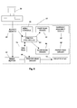
Fig. 8 is a block diagram of the electronic control system of a
printer 20, which is one example of a control system for use with a
print head 10 in accordance with the present invention. The printer
20 includes a buffer memory 40 for receiving a print file in the
form of signals from a host computer 30, an image buffer 42 for
storing printing data, and a printer controller 60 that controls the
overall operation of the printer 10. Connected to the printer
controller 60 are a fast scan driver 62 for a carriage assembly
drive motor 66, a slow scan driver 64 for a paper feed drive motor
68, and a head driver 44 for the print head 10. Optionally, there is
a data store 70 for storing parameters for controlling the
interlaced and mutual interstitial printing operation in accordance
with the present invention. Host computer 30 may be any suitable
programmable computing device such as personal computer with a
Pentium III microprocessor supplied by Intel Corp. USA, for
instance, with memory and a graphical interface such as Windows 98
as supplied by Microsoft Corp. USA. The printer controller 60 may
include a computing device, e.g. microprocessor, for instance it may
be a microcontroller. In particular, it may include a programmable
printer controller, for instance a programmable digital logic
element such as a Programmable Array Logic (PAL), a Programmable
Logic Array, a Programmable Gate Array, especially a Field
Programmable Gate Array (FPGA). The use of an FPGA allows subsequent
programming of the printer device, e.g. by downloading the required
settings of the FPGA.
The user of printer 20 can optionally set values into the data
store 70 so as to modify the operation of the printer head 10. The
user can for instance set values into the data store 70 by means of
a menu console 46 on the printer 20. Alternatively, these parameters
may be set into the data store 70 from host computer 30, e.g. by
manual entry via a keyboard. For example, based on data specified
and entered by the user, a printer driver (not shown) of the host
computer 30 determines the various parameters that define the
printing operations and transfers these to the printer controller 60
for writing into the data store 70, e.g. the resolution. One aspect
of the present invention is that the printer controller 60 controls
the operation of printer head 10 in accordance with settable
parameters stored in data store 70. Based on these parameters, the
printer controller reads the required information contained in the
printing data stored in the buffer memory 40 and sends control
signals to the drivers 62, 64 and 44. In particular controller 60 is
adapted for a dot matrix printer for printing an image on a printing
medium, the control unit comprising, software or hardware means for
controlling printing of the image as at least one set of
monochromatic mutually interstitially printed images, and software
or hardware means for setting the resolution. The controller may be
used for independently setting the resolution. The controller is
also adapted to control the operation of the printing head 10 so
that each mutually interstitial printing step and/or each
interlacing step is a pass of the printing head 10 at the
appropriate resolution. As explained above the printing head has an
array of marker elements under the control of the controller. For
instance the controller may be adapted so that for a specific
resolution the speed of the head in the fast scan direction and the
sequence of firing of the staggered nozzles is controlled.
For instance, the printing data is broken down into the
individual colour components to obtain image data in the form of a
bit map for each colour component which is stored in the receive
buffer memory 30. In accordance with control signals from the
printer controller 60, the head driver 44 reads out the colour
component image data from the image buffer memory 52 in accordance
with a specified resolution to drive the speed and the array(s) of
nozzles on the print head 10 to achieve the required resolution.
As indicated above the controller 60 may be programmable, e.g.
it may include a microprocessor or an FPGA. In accordance with
embodiments of the present invention a printer in accordance with
the present invention may be programmed to provide different
resolutions. For example, the basic model of the printer may provide
selection of one resolution only. An upgrade in the form of a
program to download into the microprocessor or FPGA of the
controller 60 may provide additional selection functionality, e.g. a
plurality of resolutions. Accordingly, the present invention
includes a computer program product which provides the functionality
of any of the methods according to the present invention when
executed on a computing device. Further, the present invention
includes a data carrier such as a CD-ROM or a diskette which stores
the computer product in a machine readable form and which executes
at least one of the methods of the invention when executed on a
computing device. Nowadays, such software is often offered on the
Internet or a company Intranet for download, hence the present
invention includes transmitting the printing computer product
according to the present invention over a local or wide area
network. The computing device may include one of a microprocessor
and an FPGA.
The data store 70 may comprise any suitable device for storing
digital data as known to the skilled person, e.g. a register or set
of registers, a memory device such as RAM, EPROM or solid state
memory.
While the invention has been shown and described with reference
to a preferred embodiment, it will be understood by those skilled in
the art that various changes or modifications in form and detail may
be made without departing from the scope and spirit of this
invention. For instance, the preparation for the printing file to
carry out the above mentioned printed embodiments may be prepared by
the host computer 30 and the printer 20 simply prints in accordance
with this file as a slave device of the host computer 30. Hence, the
present invention includes that the printing schemes of the present
invention are implemented in software on a host computer and printed
on a printer which carries out the instructions from the host
computer without amendment. Accordingly, the present invention
includes a computer program product which provides the functionality
of any of the methods according to the present invention when
executed on a computing device which is associated with a printing
head, that is the printing head and the programmable computing
device may be included with the printer or the programmable device
may be a computer or computer system, e.g. a Local Area Network
connected to a printer. The printer may be a network printer.
Further, the present invention includes a data carrier such as a CD-ROM
or a diskette which stores the computer product in a machine
readable form and which can execute at least one of the methods of
the invention when the program stored on the data carrier is
executed on a computing device. The computing device may include a
personal computer or a work station. Nowadays, such software is
often offered on the Internet or a company Intranet for download,
hence the present invention includes transmitting the printing
computer product according to the present invention over a local or
wide area network.