EP1364790A2 - Ink-jet printing head having a plurality of actuator units and/or a plurality of manifold chambers - Google Patents
Ink-jet printing head having a plurality of actuator units and/or a plurality of manifold chambers Download PDFInfo
- Publication number
- EP1364790A2 EP1364790A2 EP03011458A EP03011458A EP1364790A2 EP 1364790 A2 EP1364790 A2 EP 1364790A2 EP 03011458 A EP03011458 A EP 03011458A EP 03011458 A EP03011458 A EP 03011458A EP 1364790 A2 EP1364790 A2 EP 1364790A2
- Authority
- EP
- European Patent Office
- Prior art keywords
- nozzles
- ink
- manifold
- row
- printing head
- Prior art date
- Legal status (The legal status is an assumption and is not a legal conclusion. Google has not performed a legal analysis and makes no representation as to the accuracy of the status listed.)
- Granted
Links
Images


Classifications
-
- B—PERFORMING OPERATIONS; TRANSPORTING
- B41—PRINTING; LINING MACHINES; TYPEWRITERS; STAMPS
- B41J—TYPEWRITERS; SELECTIVE PRINTING MECHANISMS, i.e. MECHANISMS PRINTING OTHERWISE THAN FROM A FORME; CORRECTION OF TYPOGRAPHICAL ERRORS
- B41J2/00—Typewriters or selective printing mechanisms characterised by the printing or marking process for which they are designed
- B41J2/005—Typewriters or selective printing mechanisms characterised by the printing or marking process for which they are designed characterised by bringing liquid or particles selectively into contact with a printing material
- B41J2/01—Ink jet
- B41J2/135—Nozzles
- B41J2/14—Structure thereof only for on-demand ink jet heads
- B41J2/14201—Structure of print heads with piezoelectric elements
- B41J2/14209—Structure of print heads with piezoelectric elements of finger type, chamber walls consisting integrally of piezoelectric material
- B41J2002/14225—Finger type piezoelectric element on only one side of the chamber
-
- B—PERFORMING OPERATIONS; TRANSPORTING
- B41—PRINTING; LINING MACHINES; TYPEWRITERS; STAMPS
- B41J—TYPEWRITERS; SELECTIVE PRINTING MECHANISMS, i.e. MECHANISMS PRINTING OTHERWISE THAN FROM A FORME; CORRECTION OF TYPOGRAPHICAL ERRORS
- B41J2/00—Typewriters or selective printing mechanisms characterised by the printing or marking process for which they are designed
- B41J2/005—Typewriters or selective printing mechanisms characterised by the printing or marking process for which they are designed characterised by bringing liquid or particles selectively into contact with a printing material
- B41J2/01—Ink jet
- B41J2/135—Nozzles
- B41J2/14—Structure thereof only for on-demand ink jet heads
- B41J2/14201—Structure of print heads with piezoelectric elements
- B41J2002/14306—Flow passage between manifold and chamber
-
- B—PERFORMING OPERATIONS; TRANSPORTING
- B41—PRINTING; LINING MACHINES; TYPEWRITERS; STAMPS
- B41J—TYPEWRITERS; SELECTIVE PRINTING MECHANISMS, i.e. MECHANISMS PRINTING OTHERWISE THAN FROM A FORME; CORRECTION OF TYPOGRAPHICAL ERRORS
- B41J2/00—Typewriters or selective printing mechanisms characterised by the printing or marking process for which they are designed
- B41J2/005—Typewriters or selective printing mechanisms characterised by the printing or marking process for which they are designed characterised by bringing liquid or particles selectively into contact with a printing material
- B41J2/01—Ink jet
- B41J2/135—Nozzles
- B41J2/14—Structure thereof only for on-demand ink jet heads
- B41J2002/14419—Manifold
Definitions
- the present invention relates in general to an ink-jet printing head, and more particularly to the construction of a large-sized ink-jet printing head having a large number of nozzles arranged in at least one row.
- a prior art ink-jet printing head of on-demand type includes a cavity unit consisting of a plurality of plates superposed on each other so as to define ink delivery passages. These plates include a nozzle plate having a plurality of nozzles, a base plate partially defining pressure chambers corresponding to the respective nozzles, and manifold plates partially defining manifold chambers which communicate with an ink supply source and the above-indicated pressure chambers.
- the ink-jet printing head further includes a piezoelectric actuator which includes piezoelectric ceramic plates, and internal electrodes in the form of common electrodes and arrays of individual electrodes formed on the piezoelectric ceramic plates such that the common electrodes and the individual electrode arrays are alternately superposed on each other.
- the piezoelectric actuator and the cavity unit are bonded together such that active portions existing between the common electrode and the respective individual electrode are aligned with the respective pressure chambers.
- a printing operation is performed by an ink-jet printing head in a direction of width of a recording medium such as a sheet of paper, which direction is perpendicular to a direction of feeding of the recording medium.
- the direction of width and the direction of feeding of the paper sheet will be respectively referred to as “primary scanning direction” and “secondary scanning direction” where appropriate.
- the printing operation is performed such that rows of the nozzles of the ink-jet printing head are parallel to the direction of feeding of the paper sheet (the secondary scanning direction).
- images can be printed during each one movement of the carriage in the primary scanning direction, in the corresponding area of the paper sheet whose dimension in the secondary scanning direction is substantially equal to the length of each row of the nozzles.
- the ink-jet printing head has a plurality of parallel rows of nozzles, each of which has a length of one inch (25.4mm) and consists of 72 nozzles, and the nozzles in the parallel rows are arranged such that the nozzles of one row and the nozzles of the adjacent row are positioned in a zigzag pattern.
- the area in which a printing operation is performed on the paper sheet during one movement of the ink-jet printing head in the primary scanning direction has a dimension of one inch in the secondary scanning direction. This dimension may be referred to as "maximum printable height" per one movement of the ink-jet printing head in the primary scanning direction.
- each manifold chamber formed in the cavity unit between the nozzles in the corresponding row and the ink supply source, is provided to store a suitable volume of an ink supplied from the ink supply source, and is arranged to re-fill the pressure chambers with the ink when the actuator is operated according to printing commands, to deliver the ink from the selected pressure chambers to the corresponding nozzles so that droplets of the ink are jetted from the nozzles onto the paper sheet.
- the cavity unit has a relatively large number of nozzles arranged in each row, the ratio of the volume of the corresponding manifold chamber to the entire volume of the cavity unit must be increased for the reason described below.
- each manifold chamber must be increased with an increase in the number of the nozzles in the corresponding row.
- a mere increase in the length of the manifold chamber in the direction of extension of the row of the nozzles will cause the following problems.
- the rate or amount of flow of the ink tends to decrease in the direction of the flow due to a resistance to the flow of the ink mass in contact with the wall surfaces of the manifold chamber.
- a pressure wave of the ink in the pressure chamber includes a reverse component propagating in a direction toward the manifold chamber, as well as a forward component propagating in a direction toward the corresponding nozzle.
- a change in the configuration of each manifold chamber, in particular, its longitudinal dimension requires corresponding changes in the nominal magnitude and timing of operation of the actuator, and in the nominal waveform of the pressure wave indicated above.
- a cavity unit whose rows of nozzles has a length of one inch (having a comparatively small number of nozzles) and a cavity unit whose rows of nozzles have a length of two inches (having a comparatively large number of nozzles) have different nominal pressure waves of the ink in the pressure chambers, and should therefore have different designs in basic arrangements such as different magnitudes and timings of operation of the actuator, leading to problems of an increase in the required cost of development of the cavity units and an increase in the time required to complete the ink-jet printing heads as commercial products.
- the nozzles and pressure chambers can be formed in the plates of the cavity unit, with the nominal spacing pitches or distances with high accuracy, irrespective of the number of the nozzles and pressure chambers, where the nozzles and pressure chambers are formed by laser machining or etching operations in those plates formed of a metallic or synthetic material.
- the length of the piezoelectric ceramic plate should necessarily be increased with an increase in the number of the nozzles.
- the piezoelectric actuator is fabricated by pressing and then firing a laminar structure wherein piezoelectric ceramic plates each having the common electrode formed thereon in a predetermined pattern and piezoelectric ceramic plates each having the individual electrodes formed in a predetermined pattern are alternately superposed on each other.
- the dimensions of the piezoelectric ceramic plates in the directions of length, width and thickness are reduced due to shrinkage of the plates as a result of a firing operation.
- the amount of shrinkage of the piezoelectric ceramic plates in the direction of length (perpendicular to the direction of extension of the rows of the nozzles) is considerably large.
- the spacing distance between the adjacent individual electrodes in the direction of length of the piezoelectric plates is determined with the above-indicated amount of shrinkage (shrinkage ratio) taken into account.
- an ink-jet printing head including a cavity unit and an actuator which are superposed on each other, the cavity unit having (a) a plurality of nozzles open in a front surface thereof and arranged in at least one row, (b) a plurality of pressure chambers corresponding to the nozzles, respectively, (c) a plurality of communication passages for communication between the respective pressure chambers and the respective nozzles, and (d) a manifold portion for storing an ink supplied from an ink supply source and re-filling the pressure chambers when the ink is delivered from the pressure chambers to the nozzles, the actuator having a plurality of active portions which correspond to the pressure chambers, respectively and which are selectively operable to deliver the ink from the corresponding nozzles, wherein each of at least one of the manifold portion and the actuator consists of a plurality of mutually independent divisions which correspond to respective length portions of each of the above-indicated at least one row of
- each of those manifold chambers may be formed so as to be identical with the manifold chamber formed in the cavity unit of an already developed or existing printing head, which manifold chamber has the same length as the plurality of manifold chambers formed in the cavity unit of the present ink-jet printing head.
- the present ink-jet printing head with the cavity unit having a larger number of nozzles than the existing cavity unit has the same printing capability as the existing ink-jet printing head.
- the provision of the plurality of manifold chambers according to the present invention permits easy and economical manufacture of a large-sized ink-jet printing head which has the same basic functions as the already developed or existing printing head. Further, the plurality of manifold chambers need not have a length so large as to cause an increase in the resistance to a flow of the ink therethrough, so that it is not necessary to increase the width of each manifold chamber, for reducing the ink flow resistance. In this respect, the cavity unit can be small-sized.
- the plurality of divisions of the manifold portion in the form of the manifold chambers are arranged in a direction substantially parallel to the direction of extension of the above-indicated at least one row of the nozzles, it is possible to reduce the surface area of the cavity unit as viewed in its plane perpendicular to the above-indicated front surface in which the nozzles are open.
- each of those actuator units may be formed so as to be identical with the already developed or existing actuator.
- the provision of the plurality of actuator units according to the present invention permits easy and economical manufacture of a large-sized ink-jet printing head, by utilizing an actuator of an already developed or existing ink-jet printing head, such that the present printing head has the same basicsolutions as the existing printing head and is operable with the same drive voltage and at the same timing as in the existing printing head.
- the manifold portion consists of a plurality of mutually independent manifold chambers as the above-indicated plurality of mutually independent divisions which correspond to the respective length portions of each row of the nozzles and each of which is held in communication with a group of the pressure chambers communicating with a corresponding one of the length portions of each row of the nozzles.
- the ink-jet printing head has both of the advantages described above with respect to the provision of the plurality of mutually independent manifold chambers and the provision of the plurality of mutually independent actuator units.
- the plurality of nozzles are arranged in a plurality of substantially parallel rows, and the plurality of mutually independent divisions of the manifold portion consist of a plurality of sets of manifold chambers which respectively correspond to the plurality of substantially parallel rows of the nozzles, each of the sets of manifold chambers consisting of a plurality of mutually independent manifold chambers which correspond to the respective length portions of each row of the nozzles.
- This arrangement permits reduction in the above-indicated surface area of the cavity unit, even where the ink-jet printing head is arranged to perform a full-color printing operation using the four rows of nozzles corresponding to black, cyan, yellow and magenta, for instance.
- the actuator consists of a plurality of mutually independent actuator units as the above-indicated plurality of mutually independent divisions which correspond to the respective groups of the pressure chambers corresponding to the respective length portions of each row of the nozzles.
- the plurality of mutually independent divisions of the actuator consist of a plurality of actuator units which are disposed such that end faces of adjacent ones of the plurality of actuator units are opposed to each other in the direction substantially parallel to the direction of extension of the at least one row of the nozzles, and such that a distance between each of the end faces of the adjacent ones of the actuator units and one of the plurality of active portions of a corresponding one of the adjacent actuator units which is nearest to the end face in question is larger than a half of a spacing pitch of the active portions in each of the plurality of actuator units.
- the number of the nozzles arranged in each row can be easily increased while maintaining the spacing pitch of the nozzles in the existing printing head, by using the two or more actuator units which are the same as the actuator of the existing printing head and which have a length that is a fraction of the length of each row of the nozzles. Accordingly, the amount of shrinkage of each actuator unit is reduced, and the amount of variation in the spacing distance of the active portions of the actuator can be accordingly reduced.
- the present arrangement permits efficient and economical manufacture of the actuator with a high degree of dimensional accuracy.
- the ink-jet printing head according to the fourth preferred form of the invention described above can be easily manufactured such that the length of each row of the nozzles is a multiple of the length of each actuator unit.
- the end faces of the adjacent ones of the actuator units are spaced apart from each other.
- the communication passages for communication between the pressure chambers and the corresponding nozzles in the cavity unit are inclined with respect to a direction perpendicular to the front surface in which the plurality of nozzles are open.
- the plurality of actuator units may include two actuator units disposed adjacent to each other in the direction substantially parallel to the direction of extension of the at least one row of the nozzles.
- the communication passages include two groups of communication passages which correspond to the above-indicated two actuator units and which are formed such that the communication passages of one of the two groups and the communication passages of the other of the two groups are formed symmetrically with each other with respect to a plane perpendicular to the front surface of the cavity unit.
- the cavity unit may be a laminar structure consisting of a plurality of plates superposed one ach other, and the communication passages are inclined with respect to a direction of lamination of the plurality of plates.
- a spacing pitch of the plurality of active portions of the actuator and a spacing pitch of the plurality of pressure chambers are equal to a spacing pitch of the plurality of nozzles.
- the spacing arrangement of the active portions, pressure chambers and nozzles in the above-indicated fourth preferred form of the invention permits the use of an already developed or existing actuator to manufacture a large-sized high-speed ink-jet printing head which has the same basic functions as an printing head including the existing actuator and which is operable with the same drive voltage and at the same timing as in the existing printing head.
- the plurality of nozzles are arranged in a plurality of rows, and the plurality of active portions of the actuator are arranged in a plurality of rows corresponding to the plurality of rows of the nozzles.
- the plurality of nozzles are arranged in four rows.
- This form of the invention provides a compact full-color ink-jet printing head.
- each of the plurality of mutually independent divisions of the manifold portion consists of a plurality of mutually independent manifold chambers which are provided for a corresponding one of the length portions of each row of the nozzles and which are arranged in a direction perpendicular to the direction of extension of the at least one row of the nozzles
- each of the plurality of mutually independent divisions of the actuator consists of a plurality of mutually independent actuator units which respectively correspond to the length portions of each row of the nozzle, each of the plurality of mutually independent actuator units corresponding to a plurality of rows of the pressure chambers which respectively correspond to the plurality of mutually independent manifold chambers of a corresponding one of the plurality of mutually independent divisions of the manifold portion and which are arranged in the direction perpendicular to the direction of extension of the at least one row of the nozzles.
- the eighth preferred form of the invention provides a large-sized ink-jet printing head wherein the two or more rows of pressure chambers are provided for each length portion of each row of the nozzles, so that the printing head is capable of printing a high-density image, owing to a density of the nozzles in the direction of extension of their row or rows, which is a multiple of the density of the pressure chambers (and the active portions of the actuator) in the direction of extension of their rows.
- each of the plurality of mutually independent divisions of the manifold portion consists of a single manifold chamber which are provided for a corresponding one of the length portions of each row of the nozzles.
- the plurality of nozzles are arranged in a plurality of rows, and the plurality of mutually independent divisions of the manifold portion consist of a plurality of sets of manifold chambers which respectively correspond to the plurality of rows of the nozzles, each of the sets of manifold chambers consisting of a plurality of mutually independent manifold chambers which correspond to the respective length portions of a corresponding one of the rows of the nozzles and which store inks supplied from respective different ink supply sources.
- the plurality of nozzles are arranged in four rows for delivering inks of four colors, such as black, cyan, magenta and yellow, respectively.
- the manifold portion consists of a plurality of mutually independent elongate manifold chambers which correspond to the respective length portions of each row of the nozzles, and each of the mutually independent elongate manifold chamber extending in the direction substantially parallel to the direction of extension of the at least one row of the nozzles, and being held in communication, at one of opposite longitudinal end portions thereof, with the ink supply source.
- the plurality of mutually independent elongate manifold chambers consist of two elongate manifold chambers which correspond to respective two length portions of each row of the nozzles, each one of these two elongate manifold chambers being held in communication with the ink supply source, at one of opposite longitudinal end portions thereof which is remote from the other of the two elongate manifold chambers in the direction of extension of the two elongate manifold chambers.
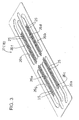
- the ink-jet printing head 10 of piezoelectric type constructed according to one embodiment of the present invention includes a cavity unit 11 and a piezoelectric actuator 12.
- the piezoelectric actuator 12 which is of a planar type, is bonded to an upper surface of a metallic base plate 22 of the cavity unit 11, and a flexible flat cable 13 for connection with an external device is superposed on and bonded by an adhesive to an upper surface of the planar piezoelectric actuator 12, as shown in Figs. 5 and 6A.
- the above-indicated cavity unit 11 is constructed as shown in Figs, 2-6. Described in detail, the cavity unit 11 is a laminar structure consisting of a total of nine relatively thin plates superposed on each other and bonded together by an adhesive.
- the nine thin plates consist of a nozzle plate 14, an intermediate plate 15, a damper plate 16, two manifold plates 17, 18, three spacer plates 19, 20, 21, and the above-indicated base plate 22, which has a plurality of pressure chambers 23.
- the nozzle plate 14 is formed of a synthetic resin, while the other plates 15-22 are formed from plates of a steel alloy including 42% of nickel and have thickness values of about 50-150 ⁇ m.
- the above-indicated nozzle plate 14 has nozzles 24 which are open in a front surface of the cavity unit 11 and each of which has an extremely small diameter (about 25 ⁇ m in this embodiment).
- the nozzles 24 are arranged in four parallel rows formed so as to extend in a first direction of the nozzle plate 14 (in the longitudinal direction of the cavity unit 11, which is an X-axis direction indicated in Figs. 1 and 2), such that the nozzles 24a and 24b in the respective two adjacent rows are arranged in a zigzag pattern, while the nozzles 24c and 24d in the respective two other adjacent rows are also arranged in a zigzag pattern.
- the multiple nozzles 24a in the first row and the multiple nozzles 24b in the second row are arranged at a predetermined small pitch P along respective two parallel reference lines (not shown) extending in the above-indicated first direction, such that each of the nozzles 24a is positioned in between the adjacent nozzles 24b in the direction of extension of the reference lines, whereby the nozzles 24a and the nozzles 24b are arranged in a zigzag pattern or in a staggered fashion.
- the multiple nozzles 24c in the third row and the multiple nozzles 24d in the fourth row are arranged at the predetermined small pitch P along respective two parallel reference lines extending in the first direction, such that each of the nozzles 24c is positioned in between the adjacent nozzles 24d, whereby the nozzles 24c and the nozzles 24d are arranged in the zigzag pattern or staggered fashion.
- a set consisting of the first and second rows of the nozzles 24a, 24b is spaced by a suitable distance from a set consisting of the third and fourth rows of the nozzles 24c, 24d, in a second direction of the nozzle plate 24 (in the transverse or width direction of the cavity unit 11, which is a Y-direction direction also indicated in Figs. 1 and 2).
- each of the first, second, third and fourth rows has a length of two inches, and consists of a total of 150 nozzles 24, so that the present ink-jet printing head 10 has an image resolution of 75 dpi (dots per inch) in the first or X-axis direction, with the 75 nozzles 24 existing per inch.
- the pressure chambers 23 correspond to the respective nozzles 24 arranged in the four rows.
- Each piezoelectric actuator unit 12a, 12b is arranged to activate the pressure chambers 23 corresponding to the nozzles 24 in a half of the length of each of the four rows, that is, 75 pressure chambers 23.
- the first piezoelectric actuator unit 12a is formed on the first half of the upper surface of the cavity unit 11 as seen in the longitudinal direction (in the first direction described above), while the second piezoelectric actuator unit 12b is formed on the other or second half of the upper surface, as shown in Figs. 2 and 6A.
- each piezoelectric actuator unit 12a, 12b consists of a laminar structure consisting of piezoelectric: sheets 33, 34 and a top sheet 35 (which will be described) superposed on each other, such that the piezoelectric sheets 33 having individual electrodes 36 formed thereon and the piezoelectric sheets 34 having common electrodes 37 formed thereon are alternately laminated.
- the piezoelectric sheets 33, 34 have the above-indicated active portions between the individual electrodes 36 and the common electrodes 37.
- the active portions corresponding to the selected individual electrodes 36 are strained due to a longitudinal piezoelectric effect in the direction of lamination of the piezoelectric actuator unit 12a, 12b.
- the active portions are arranged in four rows corresponding to the respective four rows of the pressure chambers 23, and the active portions of each row correspond to the respective pressure chambers 23 of the corresponding row.
- each piezoelectric actuator unit 12a, 12b are parallel to the four rows of the nozzles 24 (pressure chambers 23) extending in the first direction, and are spaced apart from each other in the second direction.
- Each active portion is elongate in the above-indicated second direction (direction of width of the cavity unit 11), which is the longitudinal direction of each pressure chamber 23.
- the active portions have the same spacing pitch P as the pressure chambers 23 in the longitudinal direction of the cavity unit 11, such that the active portions of the four rows are arranged in a zigzag pattern, as is apparent from Fig. 4.
- the pressure chambers 23 are arranged in two groups which correspond to the respective two piezoelectric actuator units 12a, 12b and which are arranged and spaced apart from each other in the longitudinal direction of the base plate 22. Namely, the pressure chambers 23 of the first group corresponding to the first piezoelectric actuator unit 12a correspond to the nozzles 24 in the first half of each row as seen in the direction of extension of the row (in the first direction), while the pressure chambers 23 of the second group corresponding to the second piezoelectric actuator unit 12b correspond to the nozzles 24 in the second half of each row.
- the pressure chambers 23 of each group are arranged in four rows, with the same spacing pitch P as the nozzles 24, such that the pressure chambers 23 in the first and second rows are positioned relative to each other in a zigzag pattern, while the pressure chambers 23 in the third and fourth rows are similarly positioned relative to each other in a zigzag pattern.
- Each of the pressure chambers 23 is elongate in the direction of width of the base plate 22 (in the second direction), and is formed through the thickness of the base plate 22.
- Each of the pressure chambers 23 is held in communication at one of its opposite longitudinal ends with the corresponding nozzle 24 through a corresponding one of communication passages 25 defined by through-holes 25a, 25b, 25c, 25d, 25e, 25f and 25g which are respectively formed through the spacer plates 21, 20, 19, manifold plates 18, 17, damper plate 16 and intermediate plate 15, which are located between the base plate 22 and the nozzle plate 14.
- Each pressure chamber 23 is held in communication at the other longitudinal end with a manifold portion 26 partially defined by the manifold plates 27, 28.
- the two groups of pressure chambers 23 are spaced apart from each other by a distance L2 larger than the spacing pitch P of the pressure chambers 23, in the longitudinal direction of the base plate 22.
- This spacing of the two groups of pressure chambers 23 is provided because it is difficult to fabricate the piezoelectric actuator units 12a, 12b such that a distance L1 between the individual electrodes 36 at one end of each row and the adjacent end of the piezoelectric actuator unit 12a, 12b is equal to or smaller than a half of the spacing pitch P of the individual electrodes 36.
- the piezoelectric actuator units 12a, 12b are fabricated with the distance L1 being larger than the half of the spacing pitch P, and with the spacing distance L2 being larger than the distance L1, such that the longitudinal end faces of the two piezoelectric actuator units 12a, 12b which are opposed to each other are spaced from each other by a suitable distance (L2 - 2 x L1).
- the two groups of pressure chambers 23 are spaced apart from each other in the longitudinal direction of the base plate 22, while the nozzles 24 are equally spaced apart from each other at the predetermined spacing pitch P in the direction of extension of the rows of the nozzles 24, so that the communication passages 25 for communication of each pressure chamber 23 at its one end with the corresponding nozzle 24 are inclined with respect to the direction of lamination of the plates 15-21 of the cavity unit 11, as shown in Fig. 5.
- the communication passages 25 corresponding to the two groups of pressure chambers 23 are inclined symmetrically with each other, with respect to a plane which is parallel to the above-indicated direction of lamination and which passes a midpoint of the spacing distance L2 of the two groups, as also shown in Fig. 5.
- each of the eight manifold chambers 26a-26h has a length corresponding to a fraction of the entire length of each row of the nozzles 24, more specifically, has a length which covers the length of each group of the pressure chambers 23 (the 75 pressure chambers 23 in each of the four rows of each group).
- the cavity unit 11 has a first group of mutually independent four manifold chambers 26a, 26c, 26e and 26g corresponding to the respective four rows of the pressure chambers 23 of one of the two groups, and a second group of mutually independent four manifold chambers 26b, 26d, 26f and 26h corresponding to the respective four rows of the pressure chambers 23 of the other group, as indicated in Figs. 2 and 3.
- Each of the elongate manifold chambers 26a-26h of each group has a longitudinal end portion extending in a direction away from the other group, for communication with a corresponding one of ink supply passages 31 connected to an external ink supply source (not shown).
- each of the manifold chambers 26a, 26c, 26e and 26g of the first group is located near that of each of the manifold chambers 26b, 26d, 26f and 26h of the second group.
- Each manifold chamber 26a-26h is formed through the entire thickness of each manifold plates 17, 18, by laser machining, plasma jet machining or electrolytic etching, and is fluid-tightly closed at its upper and lower ends (as seen in Fig. 2) by the first spacer plate 19 superposed on the manifold plate 18 and the damper plate 16 underlying the manifold plate 17.
- the damper plate 16 has damper chambers 27 in the form of grooves formed in its lower surface by etching through a portion of its thickness. These damper chambers 27 have the same shape as the manifold chambers 26a-26h as viewed in the plane of the damper plate 16.
- the second spacer plate 20 partially defines flow restrictors 28 formed in alignment with the respective pressure chambers 23.
- Each of these flow restrictors 28 has a shape as shown in Fig. 6B, as seen in the plane of the second spacer plate 20. That is, each flow restrictor 28 has a large area of ink flow at its longitudinal opposite end portions 28a, 28b, and a comparatively small area of ink flow at its intermediate portion 28c.
- Each flow restrictor 28 is elongate in the longitudinal direction of the corresponding pressure chamber 23.
- the flow restrictors 28 are fluid-tightly closed at their lower end by the first spacer plate 19 underlying the second spacer plate 20, and at their upper end by the third spacer plate 21 superposed on the second spacer plate 20.
- the first spacer plate 19 has first ink passages 29 communicating with the manifold chambers 26a-26h and one longitudinal end portion 28a of each flow restrictor 28, while the third spacer plate 21 has second ink passages 30 communicating with the other longitudinal end portion 28b of each flow restrictor 28 and the corresponding end portion of each pressure chamber 23.
- the base plate 22, and the third, second and first spacer plates 21, 20, 19 have respective ink supply holes 31a, 31b, 31c, 31c of a relatively large diameter formed through their opposite longitudinal end portions.
- These ink supply holes 31a-31d cooperate to define the above-indicated ink supply passages 31, more precisely, four ink supply passages 31 in one longitudinal end portion of the cavity unit 11, and four ink supply passages 31 in the other longitudinal end portion of the cavity unit 11.
- These eight ink supply passages 31 are held in communication with the above-indicated one end portion of each manifold chamber 26a-26h of each group.
- Two filters 32 are provided to cover the upper surfaces of the opposite longitudinal end portions of the base plate 22 in which the ink supply holes 31a are open. The filters 32 are provided to remove dirt or any other foreign matters that may be contained in the ink supplied from the ink supply source such as an ink reservoir.
- each of the two piezoelectric actuator units 12a, 12b which are two divisions of the actuator 12 is a laminar structure consisting of the above-indicated piezoelectric sheets 33, 34 and top sheet 35 superposed on each other, as shown in Fig. 4 and as briefly described above.
- the laminar structure may include a total of four to ten piezoelectric sheets 33, 34 alternately superposed on each other.
- Each of these piezoelectric sheets 33, 34 and top sheet 35 has a thickness of about 30 ⁇ m. As shown in Fig.
- each of the piezoelectric sheets 33 has the individual electrodes 36 in the form of elongate strips which are aligned with the respective pressure chambers 23 of the cavity unit 11 and which are arranged in four rows (36a, 36b, 36c, 36d) parallel to the first direction (longitudinal direction of the piezoelectric sheets 33), which is parallel to the X-axis direction as indicated in Fig. 4 or the direction of extension of the rows of the nozzles 24a-24d.
- Each of the individual electrodes 36a, 36b, 36c, 36d in the four rows is elongate in the second direction (Y-axis direction), that is, in the direction of width of the piezoelectric sheets 33, and has a length substantially equal to that of each pressure chamber 23a, 23b, 23c, 23d.
- the width of the individual electrode 36a-36d is slightly smaller than that of each pressure chamber 23.
- the first row of individual electrodes 36a and the fourth row of individual electrodes 36d are located near the respective opposite long side edges of the corresponding piezoelectric sheet 33.
- the second row of individual electrodes 36b and the third row of individual electrodes 36c are located in a widthwise central portion of the corresponding piezoelectric sheet 33, between the first and fourth rows of individual electrodes 36a, 36d located adjacent to the opposite long side edges of the piezoelectric sheet 33.
- Each of the piezoelectric sheets 33 except the lowermost one has a dummy common electrode 43 aligned with a lead portion 37c of the common electrode 37 which will be described.
- the common electrode 37 formed on the upper surface of each piezoelectric sheet 34 includes two main portions 37a, 37b which are elongate in the above-indicated first direction of the cavity unit 11 (in the X-axis direction or the longitudinal direction of the piezoelectric sheet 34), and the above-indicated lead portion 37c which is connected to the main portions 37a, 37b and which extends along one of the opposite short side edges of the piezoelectric sheet 34.
- the first main portion 37a is located in alignment with an almost entire portion of each individual electrode 36a in the first row and an almost entire portion of each individual electrode 36b in the second row, as viewed in the plane of the piezoelectric sheet 34.
- Each piezoelectric sheet 34 further has dummy electrodes 38a, 38b arranged in two rows located on the respective opposite sides of the first main portion 37a such that these dummy electrodes 38a, 38b in each row are equally spaced apart from each other at the predetermined spacing pitch, and such that each dummy electrode 38a, 38b is aligned with only a portion of the corresponding individual electrode 36a, 36b in the first and second rows, as viewed in the plane of the piezoelectric sheet 34.
- each piezoelectric sheet 34 further has dummy electrodes 38c, 38d arranged in two rows located on the respective opposite sides of the second main portion 37b such that these dummy electrodes 38c, 38d in each row are equally spaced apart from each other at the predetermined spacing pitch, and such that each dummy electrode 38c, 38d is aligned with only a portion of the corresponding individual electrode 36c, 36d in the third and fourth rows, as viewed in the plane of the piezoelectric sheet 34.
- top sheet 35 On the upper surface of the top sheet 35, there are formed four rows of surface electrodes 39a, 39b, 39c, 39d aligned with the respective four rows of the individual electrodes 36a, 36b, 36c, 36d, and four surface electrodes 40 aligned with the main portions 37a, 37b of the common electrodes 37 in the first direction.
- the piezoelectric sheets 33, 34 and top sheet 35 which are superposed on the lowermost piezoelectric sheet 33 have through-holes 41 formed through their thickness, and through the surface electrodes 39a, 39b, 39c, 39d, the individual electrodes 36a, 36b, 36c, 36d and the dummy electrodes 38a, 38b, 38c, 38d.
- These through-holes 41 are filled with an electrically conductive material (formed from an electrically conductive paste), for electrically connecting the surface electrodes 39a-39d with the individual electrodes 36a-36d and dummy electrodes 38a-38d.
- the above-indicated piezoelectric sheets 33, 34 and top sheet 35 further have through-holes 42 formed through their thickness and through the surface electrodes 40 on the top sheet 35, the lead portion 37c of the common electrode 37 on each piezoelectric sheet 34 and a dummy common electrode 43 formed on the upper piezoelectric sheet 33.
- These through-holes 42 are also filled with an electrically conductive material (electrically conductive paste), for electrically connecting the surface electrodes 40 with the lead portions 37c and the dummy common electrode 43.
- each piezoelectric actuator unit 12a, 12b of the piezoelectric actuator 12 unfired layers which give_the individual electrodes 36, common electrodes 37, dummy electrodes 38, dummy common electrode 43, and surface electrodes 39, 40 are formed by screen printing using a suitable electrically conductive paste such as a paste of silver and palladium, on the surfaces of ceramic substrates which give the piezoelectric ceramic sheets 33, 34 and top sheet 35. After those layers are dried, the ceramic substrates are laminated on each other and fired into the piezoelectric sheets 33, 34 and top sheet 35 having the various electrodes indicated above.
- a suitable electrically conductive paste such as a paste of silver and palladium
- the dummy electrodes 38a, 38b, 38c, 38d are formed at respective local spots, so as to avoid electrical continuity with each other and with the common electrodes 37, and the dummy common electrode 43 is formed at a local spot, so as to avoid electrical continuity with the individual electrodes 36.
- the lower surfaces of the two actuator units 12a, 12b of the piezoelectric actuator 12 thus constructed are entirely covered by respective layers or sheets (not shown) of an adhesive agent in the form of an ink impermeable synthetic resin, and the two actuator units 12a, 12b are bonded at those sheets of the adhesive agent to the upper surface of the cavity unit 11 such that the individual electrodes 36a-36d are aligned with the respective pressure chambers 23 formed in the cavity unit 11, as shown in Figs. 5 and 6A.
- the flexible flat cable 13 is pressed onto the upper surface of each actuator unit 12a, 12b, such that electrically conductive wires (not shown) of the flexible flat cables 13 are electrically connected to the surface electrodes 39, 40.
- a predetermined high voltage is applied between all of the individual electrodes 36 and the common electrodes 37 through the surface electrodes 39, 40, for polarizing local portions of the piezoelectric sheets 33, 34 which are sandwiched between the respective individual electrodes 36 and the common electrodes 37.
- the thus polarized portions of the piezoelectric sheets 33, 34 function as the active portions of the actuator 12.
- an ink-jetting drive voltage is applied between the selected individual electrodes 36 and the common electrodes 37, through the surface electrodes 39, 40, to produce electric fields in the corresponding active portions, in the direction of polarization, so that the active portions are elongated in the direction of lamination of the piezoelectric sheets 34, 35, whereby the volumes of the corresponding pressure chambers 23a-23d are reduced.
- the ink masses in the pressure chambers 23a-23d are jetted as droplets from the corresponding nozzles 24a-24d, onto a recording medium, as indicated in Fig. 6A, so that an image in the form of ink dots is printed on the recording medium.
- the first, second, third and fourth rows of nozzles 24a, 24b, 24c and 24d are respectively used for delivering the black, cyan, yellow and magenta inks, for example.
- the first manifold chambers 26a, 26b of the respective two groups formed in the manifold plates 17, 18 are filled with the black ink
- the second manifold chambers 26c, 26d are filled with the cyan ink.
- the third manifold chambers 26e, 26f are filled with the yellow ink
- the fourth manifold chambers 26g, 26h are filled with the magenta ink.
- the manifold portion 26 has the two groups of mutually independent manifold chambers 26a, 26c, 26e and 26g, and 26b, 26d, 26f and 26h as shown in Fig. 3, each of which has the same length, the same depth and the same shape in the plane of the manifold plates 17, 18, as each of the manifold chambers of a cavity unit of an already developed or existing ink-jet printing head wherein the 75 nozzles (75 pressure chambers) are equally spaced apart from each other in each row extending in the longitudinal direction over a length of one inch.
- each of the manifold chambers 26a-26h has a length corresponding to a half of the number (150) of the pressure chambers 23 arranged over a length of two inches along a straight line parallel to the longitudinal direction of the cavity unit 11, that is, a length corresponding to the 75 pressure chambers 23 arranged over a length of one inch.
- the actuator unit 12 of the present ink-jet printing head 10 consists of the two piezoelectric actuator units 12a, 12b each of which is the same as an already developed or existing piezoelectric actuator arranged to operate the 75 pressure chambers arranged in each of the four rows and which are arranged in a spaced-apart relationship with each other in the longitudinal direction of the cavity unit 11.
- This design concept of the manifold portion 26 and the piezoelectric actuator 12 prevents a reduction in the rate or amount of flow or supply of the ink due-to a resistance to a flow of the ink through the manifold portion 26, and permits all of the pressure chambers 23 to be operated with the nominal drive voltage and at the nominal timing by the piezoelectric actuator 12, assuring adequate jetting of droplets of the ink from all of the nozzles 24 as in the prior art ink-jet printing head, even where the number of the nozzles is considerably larger in the present ink-jet printing head 10.
- the length of the manifold chambers is not increased with an increase in the number of the nozzles (with an increase in the length of each row of the nozzles), but the number of the manifold chambers corresponding to each row of the nozzles is determined or increased depending upon the number of the nozzles. Accordingly, an increase in the number of the nozzles in each row will not undesirably increase a resistance to the ink flow through the manifold portion (through each manifold chamber), which would reduce the rate or amount of supply or delivery of the ink to some of the nozzles.
- the piezoelectric actuator 12 of the present printing head can be operated to deliver the ink from the nozzles 24 in the same manner as in the existing printing head, by operating the piezoelectric actuator 12 with the same voltage, timing and waveform as in the existing printing head.
- the manifold portion 26 has the two groups of manifold chambers 26a-26h arranged in the longitudinal direction of the cavity unit 11 while the piezoelectric actuator 12 consists of the two actuator units 12a, 12b also arranged in the longitudinal direction, the manifold portion 26 and the piezoelectric actuator 12 may be modified to have three or more groups of manifold chambers or consists of three or more piezoelectric actuator units.
- the present invention permits easy, economical and efficient development and manufacture of an ink-jet printing head having desired printing capability and operating accuracy (desired density of the nozzles or ink dots per inch), by utilizing a plurality of piezoelectric actuators of an existing type, and by adopting the same design (length, depth and shape in the plane of the manifold plates) of the manifold portion of the cavity unit of an existing type, even where each row of nozzles or pressure chambers in the printing head is considerably long.
- the pressure chambers 23 consist of two groups arranged in the direction of extension of the rows of the nozzles 24 such that the two groups are spaced apart from each other by the relatively large spacing distance L2, while the nozzles 24 are equally spaced apart from each other at the predetermined relatively small pitch P ( ⁇ L2), and the communication passages 24 for communication between the pressure chambers 23 and the corresponding nozzles 24 are inclined.
- the present ink-jet printing head 10 has a larger number of nozzles 24 than in an existing printing head having a smaller number of nozzles in each row and the same spacing pitch of the nozzles as in the present printing head
- the piezoelectric actuator of the existing print head which has a smaller length in the direction of extension of the rows of the nozzles can be used as each of the two piezoelectric actuator units 12a, 12b of the piezoelectric actuator 12 of the present printing head 10, which are arranged in the direction of extension of the rows of the nozzles 24.
- each of the two piezoelectric actuator units 12a, 12b has a reduced amount of shrinkage due to firing of the actuator units, making it possible to reduce a variation in the spacing distance between the adjacent active portions, thereby permitting efficient manufacture of the piezoelectric actuator having a high degree of dimensional accuracy.
- a desired ink-jet printing head wherein the length of each row of the nozzles is two or more inches can be efficiently fabricated by using a plurality of piezoelectric actuators of the existing ink-jet printing head.
- the two piezoelectric actuator units 12a, 12b are arranged in a spaced-apart relationship with each other in the direction of extension of the rows of the nozzles 24, such that the opposed end faces of the two piezoelectric actuator units 12a, 12b are spaced apart from each other by a certain distance of gap (L2 - 2 x L1).
- this distance of gap may be almost zeroed.
- the number of the pressure chambers 23 (nozzles 24) and the number of the actuator units of the piezoelectric actuator 12, which correspond to the length of each manifold chamber 26a-26h, are not particularly limited, but may be determined as needed.
- the four manifold chambers 26a, 26c, 36e, 26g (26b, 26d, 26f, 26h) of each of the two groups are formed in substantial alignment with the respective four rows of the nozzles 24, such that each manifold chamber extends in a direction substantially parallel to the direction of extension of the rows of the nozzles 24, so that the cavity unit 11 can be made relatively compact with a relatively small surface area as viewed in its plane.
- the 150 nozzles 24 arranged in each of the four rows are held in communication with one pair of two rows of the pressure chambers 23 which lie on the same straight line parallel to the direction of the rows of the nozzles 24.
- the piezoelectric actuator 12 has two sets of the first and second actuator units 12a, 12b which are arranged in the ⁇ -axis direction
- the cavity unit 11 has two groups (first and second groups) of pressure chambers 23 which are arranged in the X-axis direction and each of which consists of eight rows of pressure chambers 23 corresponding to the respective eight rows of the individual electrodes 36 of the corresponding two first or second actuator units 12a, 12b
- the cavity unit may be provided with four rows of nozzles 24 which are formed such that 300 nozzles 24 are arranged in each of the four rows over a length of two inches and are held in communication with the four rows of pressure chambers 23 consisting of the two rows of the first group and the corresponding two rows of the second group.
- This modification provides a large-sized full-color ink-jet printing head, wherein the four rows of the nozzles 24 are assigned to the respective four colors, and are capable of printing a high-density image (150 dpi) having a maximum dimension of two inches in the secondary scanning direction (direction of feeding of the recording medium).
- the number of the rows of the active portions and the pressure chambers may be a multiple of the number of rows of the nozzles, so that the density of the nozzles in the direction of extension of the rows is a multiple of the density of the active portions and pressure chambers in the direction of extension of the rows.
- the ink-jet printing head 10 has the four rows of nozzles.
- the principle of the present invention is equally applicable to an ink-jet printing head having at least one row of nozzles.
- the actuator used for the ink-jet printing head is not limited to the piezoelectric actuator 12 utilizing piezoelectric elements.
- the actuator may include oscillating plates which define the bottom walls of the pressure chambers and which are oscillated by static electricity to deliver the ink, or include Joule-heat generating elements operable according to a drive signal to generate heat for vaporizing the ink masses within the pressure chambers, for pressurizing the ink to be delivered from the nozzles.
Abstract
Description
Claims (19)
- An ink-jet printing head including a cavity unit (11) and an actuator (12) which are superposed on each other, said cavity unit having (a) a plurality of nozzles (24) open in a front surface thereof and arranged in at least one row, (b) a plurality of pressure chambers (23) corresponding to said nozzles, respectively, (c) a plurality of communication passages (25) for communication between the respective pressure chambers and the respective nozzles, and (d) a manifold portion (26) for storing an ink supplied from an ink supply source and re-filling the pressure chambers, said actuator having a plurality of active portions which correspond to said pressure chambers, respectively and which are selectively operable to deliver the ink from the corresponding nozzles, characterized in that:each of at least one of said manifold portion (26) and said actuator (12) consists of a plurality of mutually independent divisions (26a-26h; 12a, 12b) which correspond to respective length portions of said each of said at least one row of said nozzles (24) and which are arranged in a direction substantially parallel to a direction of extension of said at least one row of said nozzles.
- An ink-jet printing head according to claim 1, wherein said manifold portion (26) consists of a plurality of mutually independent manifold chambers (26a-26h) as said plurality of mutually independent divisions which correspond to said respective length portions of said each row of said nozzles and each of which is held in communication with a group of said pressure chambers (23) communicating with a corresponding one of said respective length portions of said each row of the nozzles.
- An ink-jet printing head according to claim 1, wherein said plurality of nozzles (24) are arranged in a plurality of substantially parallel rows, and said plurality of mutually independent divisions (26a-26h) of said manifold portion (26) consist of a plurality of sets of manifold chambers which respectively correspond to said plurality of substantially parallel rows of said nozzles, each of said sets of manifold chambers consisting of a plurality of mutually independent manifold chambers which correspond to said respective length portions of said each row of said nozzles.
- An ink-jet printing head according to any one of claims 1-3, wherein said actuator (12) consists of a plurality of mutually independent actuator units (12a, 12b) as said plurality of mutually independent divisions which correspond to the respective groups of said pressure chambers corresponding to said respective length portions of said each row of the nozzles.
- An ink-jet printing head according to any one of claims 1-4, wherein said plurality of mutually independent divisions of said actuator (12) consist of a plurality of actuator units (12a, 12b) which are disposed such that end faces of adjacent ones of said plurality of actuator units are opposed to each other in the direction substantially parallel to the direction of extension of said at least one row of said nozzles (24), and such that a distance (L1) between each of the end faces of said adjacent ones of the actuator units and one of said plurality of active portions of a corresponding one of the adjacent actuator units which is nearest to said each end face is larger than a half of a spacing pitch of said active portions in each of said plurality of actuator units.
- An ink-jet printing head according to claim 5, wherein said end faces of said adjacent ones of the actuator units (12a, 12b) are spaced apart from each other.
- An ink-jet printing head according to claim 5 or 6, wherein said communication passages (25) for communication between said pressure chambers (23) and the corresponding nozzles (24) in said cavity unit (11) are inclined with respect to a direction perpendicular to said front surface in which said plurality of nozzles are open.
- An ink-jet printing head according to claim 7, wherein said plurality of actuator units include two actuator units (12a, 12b) disposed adjacent to each other in the direction substantially parallel to the direction of extension of said at least one row of said nozzle, and said communication passages (25) include two groups of communication passages which correspond to said two actuator units and which are formed such that the communication passages of one of said two groups and the communication passages of the other of said two groups are formed symmetrically with each other with respect to a plane perpendicular to said front surface.
- An ink-jet printing head according to claim 7 or 8, wherein said cavity unit (11) is a laminar structure consisting of a plurality of plates (14-22) superposed one ach other, and said communication passages (25) are inclined with respect to a direction of lamination of said plurality of plates.
- An ink-jet printing head according to any one of claims 1-9, wherein a spacing pitch of said plurality of active portions of said actuator (12) and a spacing pitch of said plurality of pressure chambers (23) are equal to a spacing pitch of said plurality of nozzles (24).
- An ink-jet printing head according to any one of claims 1-10, wherein said plurality of nozzles (24) are arranged in a plurality of rows, and said plurality of active portions of said actuator (12) are arranged in a plurality of rows corresponding to said plurality of rows of said nozzles.
- An ink-jet printing head according to any one of claims 1-11, wherein said plurality of nozzles (24) are arranged in four rows.
- An ink-jet printing head according to any one of claims 1-12, wherein each of said plurality of mutually independent divisions of said manifold portion consists of a plurality of mutually independent manifold chambers which are provided for a corresponding one of said length portions of said each row of said nozzles (24) and which are arranged in a direction perpendicular to the direction of extension of said at least one row of the nozzles, and each of said plurality of mutually independent divisions of said actuator consists of a plurality of mutually independent actuator units (12a, 12b) which respectively correspond to said length portions of said each row of said nozzle, each of said plurality of mutually independent actuator units corresponding to a plurality of rows of said pressure chambers (23) which respectively correspond to said plurality of mutually independent manifold chambers of a corresponding one of said plurality of mutually independent divisions of said manifold portion and which are arranged in the direction perpendicular to the direction of extension of said at least one row of the nozzles.
- An ink-jet printing head according to claim 13, wherein said plurality of nozzles are arranged in a plurality of rows.
- An ink-jet printing head according to any one of claims 1-12, wherein each of said plurality of mutually independent divisions of said manifold portion consists of a single manifold chamber which are provided for a corresponding one of said length portions of said each row of said nozzles (24).
- An ink-jet printing head according to any one of claims 1-15, wherein said plurality of nozzles are arranged in a plurality of rows, and said plurality of mutually independent divisions of said manifold portion consist of a plurality of sets of manifold . chambers which respectively correspond to said plurality of rows of said nozzles, each of said sets of manifold chambers consisting of a plurality of mutually independent manifold chambers which correspond to the respective length portions of a corresponding one of said rows of the nozzles and which store inks supplied from respective different ink supply sources.
- An ink-jet printing head according to any one of claims 1-16, wherein said plurality of nozzles are arranged in four rows for delivering inks of four different colors, respectively.
- An ink-jet printing head according to any one of claims 1-17, wherein said manifold portion consists of a plurality of mutually independent elongate manifold chambers (26a-26h) which correspond to said respective length portions of said each row of the nozzles, and each of said mutually independent elongate manifold chamber extending in the direction substantially parallel to the direction of extension of said at least one row of the nozzles, and being held in communication, at one of opposite longitudinal end portions thereof, with said ink supply source.
- An ink-jet printing head according to claim 18, wherein said plurality of mutually independent elongate manifold chambers consist of two elongate manifold chambers which correspond to respective two length portions of said each row of the nozzles, each one of said two elongate manifold chambers being held in communication with said ink supply source, at one of opposite longitudinal end portions thereof which is remote from the other of said two elongate manifold chambers in the direction of extension of said two elongate manifold chambers.
Applications Claiming Priority (4)
| Application Number | Priority Date | Filing Date | Title |
|---|---|---|---|
| JP2002145655A JP4051541B2 (en) | 2002-05-21 | 2002-05-21 | Inkjet printer head |
| JP2002145654A JP3931972B2 (en) | 2002-05-21 | 2002-05-21 | Inkjet printer head |
| JP2002145654 | 2002-05-21 | ||
| JP2002145655 | 2002-05-21 |
Publications (3)
| Publication Number | Publication Date |
|---|---|
| EP1364790A2 true EP1364790A2 (en) | 2003-11-26 |
| EP1364790A3 EP1364790A3 (en) | 2004-05-12 |
| EP1364790B1 EP1364790B1 (en) | 2010-09-08 |
Family
ID=29405348
Family Applications (1)
| Application Number | Title | Priority Date | Filing Date |
|---|---|---|---|
| EP03011458A Expired - Lifetime EP1364790B1 (en) | 2002-05-21 | 2003-05-20 | Ink-jet printing head having a plurality of actuator units and a plurality of manifold chambers |
Country Status (4)
| Country | Link |
|---|---|
| US (2) | US6994428B2 (en) |
| EP (1) | EP1364790B1 (en) |
| AT (1) | ATE480403T1 (en) |
| DE (1) | DE60334047D1 (en) |
Cited By (6)
| Publication number | Priority date | Publication date | Assignee | Title |
|---|---|---|---|---|
| WO2006066306A1 (en) * | 2004-12-20 | 2006-06-29 | Silverbrook Research Pty Ltd | Printhead chip having longitudinal ink supply channels |
| EP1375148B1 (en) * | 2002-06-26 | 2007-08-15 | Brother Kogyo Kabushiki Kaisha | Ink-jet printhead |
| US7367650B2 (en) | 2004-01-21 | 2008-05-06 | Silverbrook Research Pty Ltd | Printhead chip having low aspect ratio ink supply channels |
| US7441865B2 (en) | 2004-01-21 | 2008-10-28 | Silverbrook Research Pty Ltd | Printhead chip having longitudinal ink supply channels |
| US7469989B2 (en) | 2004-01-21 | 2008-12-30 | Silverbrook Research Pty Ltd | Printhead chip having longitudinal ink supply channels interrupted by transverse bridges |
| GB2547951A (en) * | 2016-03-04 | 2017-09-06 | Xaar Technology Ltd | Droplet deposition head and manifold component therefor |
Families Citing this family (13)
| Publication number | Priority date | Publication date | Assignee | Title |
|---|---|---|---|---|
| JP4507170B2 (en) * | 2004-02-23 | 2010-07-21 | ブラザー工業株式会社 | Inkjet printer head |
| JP4235820B2 (en) * | 2004-05-07 | 2009-03-11 | ブラザー工業株式会社 | Ink jet recording head, head unit, and method of manufacturing ink jet recording head |
| JP4243850B2 (en) * | 2004-05-11 | 2009-03-25 | ブラザー工業株式会社 | Multilayer piezoelectric element and ink jet recording head including the same |
| US7543918B2 (en) * | 2005-08-31 | 2009-06-09 | Brother Kogyo Kabushiki Kaisha | Liquid jetting head and method for producing the same |
| US7766460B2 (en) * | 2005-11-30 | 2010-08-03 | Brother Kogyo Kabushiki Kaisha | Liquid-droplet jetting apparatus |
| JP5194386B2 (en) * | 2006-06-03 | 2013-05-08 | ブラザー工業株式会社 | Multilayer piezoelectric actuator |
| JP2008036988A (en) * | 2006-08-08 | 2008-02-21 | Brother Ind Ltd | Droplet ejector and method of manufacturing the same |
| KR101347144B1 (en) * | 2006-12-01 | 2014-01-06 | 삼성디스플레이 주식회사 | Restrictor with structure for preventing back flow and inkjet head having the same |
| US7874654B2 (en) * | 2007-06-14 | 2011-01-25 | Hewlett-Packard Development Company, L.P. | Fluid manifold for fluid ejection device |
| JP5092802B2 (en) * | 2008-03-04 | 2012-12-05 | セイコーエプソン株式会社 | Liquid ejecting head and liquid ejecting apparatus |
| KR20110014013A (en) * | 2009-08-04 | 2011-02-10 | 삼성전기주식회사 | Inkjet head and method of menufacturing inkjet head |
| US8118410B2 (en) * | 2009-08-31 | 2012-02-21 | Hewlett-Packard Development Company, L.P. | Piezoelectric printhead and related methods |
| JP2015033838A (en) * | 2013-08-09 | 2015-02-19 | セイコーエプソン株式会社 | Liquid injection head and liquid injection device |
Citations (2)
| Publication number | Priority date | Publication date | Assignee | Title |
|---|---|---|---|---|
| JP2002036545A (en) | 2000-07-24 | 2002-02-05 | Brother Ind Ltd | Ink jet printer head and its manufacturing method |
| US20020024567A1 (en) | 2000-08-22 | 2002-02-28 | Brother Kogyo Kabushiki Kaisha | Piezoelectric ink-jet printer head and method of fabricating same |
Family Cites Families (20)
| Publication number | Priority date | Publication date | Assignee | Title |
|---|---|---|---|---|
| JPS5811171A (en) | 1981-07-14 | 1983-01-21 | Canon Inc | Recorder |
| US4680595A (en) * | 1985-11-06 | 1987-07-14 | Pitney Bowes Inc. | Impulse ink jet print head and method of making same |
| US5087930A (en) * | 1989-11-01 | 1992-02-11 | Tektronix, Inc. | Drop-on-demand ink jet print head |
| JP2606955B2 (en) * | 1990-09-17 | 1997-05-07 | シャープ株式会社 | Ink jet recording head |
| DE69309153T2 (en) * | 1992-06-04 | 1997-10-09 | Tektronix Inc | On-demand ink jet print head with improved cleaning performance |
| US5574486A (en) * | 1993-01-13 | 1996-11-12 | Tektronix, Inc. | Ink jet print heads and methos for preparing them |
| JP3638293B2 (en) | 1993-02-05 | 2005-04-13 | 富士写真フイルム株式会社 | Inkjet head |
| US5896154A (en) * | 1993-04-16 | 1999-04-20 | Hitachi Koki Co., Ltd. | Ink jet printer |
| JPH0789071A (en) | 1993-09-28 | 1995-04-04 | Canon Inc | Ink jet recorder |
| DE69431036T2 (en) * | 1993-12-24 | 2002-11-07 | Seiko Epson Corp | Lamellar ink jet recording head |
| US5907340A (en) | 1995-07-24 | 1999-05-25 | Seiko Epson Corporation | Laminated ink jet recording head with plural actuator units connected at outermost ends |
| JP3365192B2 (en) | 1996-02-22 | 2003-01-08 | セイコーエプソン株式会社 | Ink jet recording head |
| US6003971A (en) * | 1996-03-06 | 1999-12-21 | Tektronix, Inc. | High-performance ink jet print head having an improved ink feed system |
| JP2000506800A (en) * | 1996-10-30 | 2000-06-06 | フィリップス エレクトロニクス ネムローゼ フェンノートシャップ | Ink jet print head and ink jet printer |
| EP1057633B1 (en) | 1998-12-24 | 2008-09-03 | Seiko Epson Corporation | Ink jet type recording head |
| DE60000584T2 (en) | 1999-01-29 | 2003-08-14 | Seiko Epson Corp | Inkjet printhead with improved ink supply channels |
| US6827423B1 (en) | 1999-05-06 | 2004-12-07 | Seiko Epson Corporation | Liquid jetting apparatus, method of driving the same, computer-readable recording medium storing the method and image recording apparatus incorporating the same |
| JP2001246748A (en) | 1999-12-27 | 2001-09-11 | Seiko Epson Corp | Ink-jet type recording head |
| JP2001260366A (en) | 2000-03-21 | 2001-09-25 | Nec Corp | Ink jet recording head and its manufacturing method |
| JP4221544B2 (en) | 2000-10-26 | 2009-02-12 | ブラザー工業株式会社 | Piezoelectric actuator |
-
2003
- 2003-05-19 US US10/440,309 patent/US6994428B2/en not_active Expired - Lifetime
- 2003-05-20 DE DE60334047T patent/DE60334047D1/en not_active Expired - Lifetime
- 2003-05-20 AT AT03011458T patent/ATE480403T1/en not_active IP Right Cessation
- 2003-05-20 EP EP03011458A patent/EP1364790B1/en not_active Expired - Lifetime
-
2005
- 2005-07-25 US US11/187,878 patent/US7607760B2/en not_active Expired - Fee Related
Patent Citations (2)
| Publication number | Priority date | Publication date | Assignee | Title |
|---|---|---|---|---|
| JP2002036545A (en) | 2000-07-24 | 2002-02-05 | Brother Ind Ltd | Ink jet printer head and its manufacturing method |
| US20020024567A1 (en) | 2000-08-22 | 2002-02-28 | Brother Kogyo Kabushiki Kaisha | Piezoelectric ink-jet printer head and method of fabricating same |
Cited By (16)
| Publication number | Priority date | Publication date | Assignee | Title |
|---|---|---|---|---|
| EP1375148B1 (en) * | 2002-06-26 | 2007-08-15 | Brother Kogyo Kabushiki Kaisha | Ink-jet printhead |
| US8079664B2 (en) | 2004-01-21 | 2011-12-20 | Silverbrook Research Pty Ltd | Printer with printhead chip having ink channels reinforced by transverse walls |
| US8678549B2 (en) | 2004-01-21 | 2014-03-25 | Zamtec Ltd | Printhead integrated circuit having frontside inlet channels and backside ink supply channels |
| US7441865B2 (en) | 2004-01-21 | 2008-10-28 | Silverbrook Research Pty Ltd | Printhead chip having longitudinal ink supply channels |
| US7469989B2 (en) | 2004-01-21 | 2008-12-30 | Silverbrook Research Pty Ltd | Printhead chip having longitudinal ink supply channels interrupted by transverse bridges |
| US7686440B2 (en) | 2004-01-21 | 2010-03-30 | Silverbrook Research Pty Ltd | Ink storage module with a valve insert to facilitate refilling thereof |
| US7735986B2 (en) | 2004-01-21 | 2010-06-15 | Silverbrook Research Pty Ltd | Ink storage module |
| US7367650B2 (en) | 2004-01-21 | 2008-05-06 | Silverbrook Research Pty Ltd | Printhead chip having low aspect ratio ink supply channels |
| US9346276B2 (en) | 2004-01-21 | 2016-05-24 | Memjet Technology Limited | Removable printhead cartridge having plurality of printhead chips |
| US7971960B2 (en) | 2004-01-21 | 2011-07-05 | Silverbrook Research Pty Ltd | Printhead integrated circuit having longitudinal ink supply channels reinforced by transverse walls |
| US9056478B2 (en) | 2004-01-21 | 2015-06-16 | Memjet Technology Ltd. | Ink distribution member for mounting printhead integrated circuit |
| US9102152B2 (en) | 2004-01-21 | 2015-08-11 | Memjet Technology Ltd. | Removable printhead assembly for single-pass inkjet printer |
| WO2006066306A1 (en) * | 2004-12-20 | 2006-06-29 | Silverbrook Research Pty Ltd | Printhead chip having longitudinal ink supply channels |
| GB2547951A (en) * | 2016-03-04 | 2017-09-06 | Xaar Technology Ltd | Droplet deposition head and manifold component therefor |
| US10479076B2 (en) | 2016-03-04 | 2019-11-19 | Xaar Technology Limited | Droplet deposition head and manifold components therefor |
| US10682853B2 (en) | 2016-03-04 | 2020-06-16 | Xaar Technology Limited | Droplet deposition head and manifold components therefor |
Also Published As
| Publication number | Publication date |
|---|---|
| US20030218659A1 (en) | 2003-11-27 |
| EP1364790B1 (en) | 2010-09-08 |
| DE60334047D1 (en) | 2010-10-21 |
| US6994428B2 (en) | 2006-02-07 |
| US20050264618A1 (en) | 2005-12-01 |
| EP1364790A3 (en) | 2004-05-12 |
| ATE480403T1 (en) | 2010-09-15 |
| US7607760B2 (en) | 2009-10-27 |
Similar Documents
| Publication | Publication Date | Title |
|---|---|---|
| US7607760B2 (en) | Ink-jet printing head having a plurality of actuator units and/or a plurality of manifold chambers | |
| US7008049B2 (en) | Inkjet head | |
| EP1403053A1 (en) | Ink-jet head | |
| US6984027B2 (en) | Ink-jet head and ink-jet printer having ink-jet head | |
| US7824012B2 (en) | Ink jet recording head wiring pattern | |
| EP1506862B1 (en) | Inkjet head printing device | |
| JP6349649B2 (en) | Liquid ejection device | |
| US7125097B2 (en) | Ink-jet printing head in which each passage between pressure chamber and nozzle includes horizontally extending portion | |
| JP4810908B2 (en) | Inkjet head | |
| EP1493581B1 (en) | Laminated bonding structure of thin plate members and inkjet printing head | |
| EP1582352B1 (en) | Inkjet head | |
| JP6569776B2 (en) | Liquid ejection device | |
| EP2213456B1 (en) | Ink-jet head and ink-jet printer having ink-jet head | |
| JP2001219560A (en) | Ink jet recording head | |
| JP2004136668A (en) | Inkjet head | |
| JP4051541B2 (en) | Inkjet printer head | |
| US7306328B2 (en) | Ink jet printer head | |
| JP3991695B2 (en) | Inkjet head | |
| JP2005059551A (en) | Ink jet printer head | |
| JP2006062259A (en) | Inkjet head | |
| JP3931972B2 (en) | Inkjet printer head | |
| JP2005193654A (en) | Inkjet head and nozzle plate of inkjet head | |
| JPH05177832A (en) | Ink jet head printing head and electronic machinery equipped therewith | |
| JP4639610B2 (en) | Inkjet head design method and inkjet head | |
| JP4281572B2 (en) | Nozzle plate manufacturing method |
Legal Events
| Date | Code | Title | Description |
|---|---|---|---|
| PUAI | Public reference made under article 153(3) epc to a published international application that has entered the european phase |
Free format text: ORIGINAL CODE: 0009012 |
|
| AK | Designated contracting states |
Kind code of ref document: A2 Designated state(s): AT BE BG CH CY CZ DE DK EE ES FI FR GB GR HU IE IT LI LU MC NL PT RO SE SI SK TR |
|
| AX | Request for extension of the european patent |
Extension state: AL LT LV MK |
|
| PUAL | Search report despatched |
Free format text: ORIGINAL CODE: 0009013 |
|
| AK | Designated contracting states |
Kind code of ref document: A3 Designated state(s): AT BE BG CH CY CZ DE DK EE ES FI FR GB GR HU IE IT LI LU MC NL PT RO SE SI SK TR |
|
| AX | Request for extension of the european patent |
Extension state: AL LT LV MK |
|
| 17P | Request for examination filed |
Effective date: 20040927 |
|
| AKX | Designation fees paid |
Designated state(s): AT BE BG CH CY CZ DE DK EE ES FI FR GB GR HU IE IT LI LU MC NL PT RO SE SI SK TR |
|
| 17Q | First examination report despatched |
Effective date: 20061127 |
|
| GRAP | Despatch of communication of intention to grant a patent |
Free format text: ORIGINAL CODE: EPIDOSNIGR1 |
|
| RTI1 | Title (correction) |
Free format text: INK-JET PRINTING HEAD HAVING A PLURALITY OF ACTUATOR UNITS AND A PLURALITY OF MANIFOLD CHAMBERS |
|
| GRAS | Grant fee paid |
Free format text: ORIGINAL CODE: EPIDOSNIGR3 |
|
| GRAA | (expected) grant |
Free format text: ORIGINAL CODE: 0009210 |
|
| AK | Designated contracting states |
Kind code of ref document: B1 Designated state(s): AT BE BG CH CY CZ DE DK EE ES FI FR GB GR HU IE IT LI LU MC NL PT RO SE SI SK TR |
|
| REG | Reference to a national code |
Ref country code: GB Ref legal event code: FG4D |
|
| REG | Reference to a national code |
Ref country code: CH Ref legal event code: EP |
|
| REG | Reference to a national code |
Ref country code: IE Ref legal event code: FG4D |
|
| REF | Corresponds to: |
Ref document number: 60334047 Country of ref document: DE Date of ref document: 20101021 Kind code of ref document: P |
|
| REG | Reference to a national code |
Ref country code: NL Ref legal event code: VDEP Effective date: 20100908 |
|
| PG25 | Lapsed in a contracting state [announced via postgrant information from national office to epo] |
Ref country code: FI Free format text: LAPSE BECAUSE OF FAILURE TO SUBMIT A TRANSLATION OF THE DESCRIPTION OR TO PAY THE FEE WITHIN THE PRESCRIBED TIME-LIMIT Effective date: 20100908 Ref country code: AT Free format text: LAPSE BECAUSE OF FAILURE TO SUBMIT A TRANSLATION OF THE DESCRIPTION OR TO PAY THE FEE WITHIN THE PRESCRIBED TIME-LIMIT Effective date: 20100908 |
|
| PG25 | Lapsed in a contracting state [announced via postgrant information from national office to epo] |
Ref country code: CY Free format text: LAPSE BECAUSE OF FAILURE TO SUBMIT A TRANSLATION OF THE DESCRIPTION OR TO PAY THE FEE WITHIN THE PRESCRIBED TIME-LIMIT Effective date: 20100908 Ref country code: SI Free format text: LAPSE BECAUSE OF FAILURE TO SUBMIT A TRANSLATION OF THE DESCRIPTION OR TO PAY THE FEE WITHIN THE PRESCRIBED TIME-LIMIT Effective date: 20100908 |
|
| PG25 | Lapsed in a contracting state [announced via postgrant information from national office to epo] |
Ref country code: SE Free format text: LAPSE BECAUSE OF FAILURE TO SUBMIT A TRANSLATION OF THE DESCRIPTION OR TO PAY THE FEE WITHIN THE PRESCRIBED TIME-LIMIT Effective date: 20100908 Ref country code: GR Free format text: LAPSE BECAUSE OF FAILURE TO SUBMIT A TRANSLATION OF THE DESCRIPTION OR TO PAY THE FEE WITHIN THE PRESCRIBED TIME-LIMIT Effective date: 20101209 Ref country code: NL Free format text: LAPSE BECAUSE OF FAILURE TO SUBMIT A TRANSLATION OF THE DESCRIPTION OR TO PAY THE FEE WITHIN THE PRESCRIBED TIME-LIMIT Effective date: 20100908 |
|
| PG25 | Lapsed in a contracting state [announced via postgrant information from national office to epo] |
Ref country code: EE Free format text: LAPSE BECAUSE OF FAILURE TO SUBMIT A TRANSLATION OF THE DESCRIPTION OR TO PAY THE FEE WITHIN THE PRESCRIBED TIME-LIMIT Effective date: 20100908 Ref country code: PT Free format text: LAPSE BECAUSE OF FAILURE TO SUBMIT A TRANSLATION OF THE DESCRIPTION OR TO PAY THE FEE WITHIN THE PRESCRIBED TIME-LIMIT Effective date: 20110110 Ref country code: CZ Free format text: LAPSE BECAUSE OF FAILURE TO SUBMIT A TRANSLATION OF THE DESCRIPTION OR TO PAY THE FEE WITHIN THE PRESCRIBED TIME-LIMIT Effective date: 20100908 Ref country code: SK Free format text: LAPSE BECAUSE OF FAILURE TO SUBMIT A TRANSLATION OF THE DESCRIPTION OR TO PAY THE FEE WITHIN THE PRESCRIBED TIME-LIMIT Effective date: 20100908 Ref country code: IT Free format text: LAPSE BECAUSE OF FAILURE TO SUBMIT A TRANSLATION OF THE DESCRIPTION OR TO PAY THE FEE WITHIN THE PRESCRIBED TIME-LIMIT Effective date: 20100908 Ref country code: RO Free format text: LAPSE BECAUSE OF FAILURE TO SUBMIT A TRANSLATION OF THE DESCRIPTION OR TO PAY THE FEE WITHIN THE PRESCRIBED TIME-LIMIT Effective date: 20100908 |
|
| PG25 | Lapsed in a contracting state [announced via postgrant information from national office to epo] |
Ref country code: ES Free format text: LAPSE BECAUSE OF FAILURE TO SUBMIT A TRANSLATION OF THE DESCRIPTION OR TO PAY THE FEE WITHIN THE PRESCRIBED TIME-LIMIT Effective date: 20101219 Ref country code: BE Free format text: LAPSE BECAUSE OF FAILURE TO SUBMIT A TRANSLATION OF THE DESCRIPTION OR TO PAY THE FEE WITHIN THE PRESCRIBED TIME-LIMIT Effective date: 20100908 |
|
| PLBE | No opposition filed within time limit |
Free format text: ORIGINAL CODE: 0009261 |
|
| STAA | Information on the status of an ep patent application or granted ep patent |
Free format text: STATUS: NO OPPOSITION FILED WITHIN TIME LIMIT |
|
| 26N | No opposition filed |
Effective date: 20110609 |
|
| PG25 | Lapsed in a contracting state [announced via postgrant information from national office to epo] |
Ref country code: DK Free format text: LAPSE BECAUSE OF FAILURE TO SUBMIT A TRANSLATION OF THE DESCRIPTION OR TO PAY THE FEE WITHIN THE PRESCRIBED TIME-LIMIT Effective date: 20100908 |
|
| REG | Reference to a national code |
Ref country code: DE Ref legal event code: R097 Ref document number: 60334047 Country of ref document: DE Effective date: 20110609 |
|
| PG25 | Lapsed in a contracting state [announced via postgrant information from national office to epo] |
Ref country code: MC Free format text: LAPSE BECAUSE OF NON-PAYMENT OF DUE FEES Effective date: 20110531 |
|
| REG | Reference to a national code |
Ref country code: CH Ref legal event code: PL |
|
| PG25 | Lapsed in a contracting state [announced via postgrant information from national office to epo] |
Ref country code: CH Free format text: LAPSE BECAUSE OF NON-PAYMENT OF DUE FEES Effective date: 20110531 Ref country code: LI Free format text: LAPSE BECAUSE OF NON-PAYMENT OF DUE FEES Effective date: 20110531 |
|
| REG | Reference to a national code |
Ref country code: IE Ref legal event code: MM4A |
|
| PG25 | Lapsed in a contracting state [announced via postgrant information from national office to epo] |
Ref country code: IE Free format text: LAPSE BECAUSE OF NON-PAYMENT OF DUE FEES Effective date: 20110520 |
|
| PG25 | Lapsed in a contracting state [announced via postgrant information from national office to epo] |
Ref country code: LU Free format text: LAPSE BECAUSE OF NON-PAYMENT OF DUE FEES Effective date: 20110520 |
|
| PG25 | Lapsed in a contracting state [announced via postgrant information from national office to epo] |
Ref country code: TR Free format text: LAPSE BECAUSE OF FAILURE TO SUBMIT A TRANSLATION OF THE DESCRIPTION OR TO PAY THE FEE WITHIN THE PRESCRIBED TIME-LIMIT Effective date: 20100908 Ref country code: BG Free format text: LAPSE BECAUSE OF FAILURE TO SUBMIT A TRANSLATION OF THE DESCRIPTION OR TO PAY THE FEE WITHIN THE PRESCRIBED TIME-LIMIT Effective date: 20101208 |
|
| PG25 | Lapsed in a contracting state [announced via postgrant information from national office to epo] |
Ref country code: HU Free format text: LAPSE BECAUSE OF FAILURE TO SUBMIT A TRANSLATION OF THE DESCRIPTION OR TO PAY THE FEE WITHIN THE PRESCRIBED TIME-LIMIT Effective date: 20100908 |
|
| REG | Reference to a national code |
Ref country code: FR Ref legal event code: PLFP Year of fee payment: 14 |
|
| REG | Reference to a national code |
Ref country code: FR Ref legal event code: PLFP Year of fee payment: 15 |
|
| REG | Reference to a national code |
Ref country code: FR Ref legal event code: PLFP Year of fee payment: 16 |
|
| PGFP | Annual fee paid to national office [announced via postgrant information from national office to epo] |
Ref country code: FR Payment date: 20200421 Year of fee payment: 18 Ref country code: DE Payment date: 20200417 Year of fee payment: 18 |
|
| PGFP | Annual fee paid to national office [announced via postgrant information from national office to epo] |
Ref country code: GB Payment date: 20200429 Year of fee payment: 18 |
|
| REG | Reference to a national code |
Ref country code: DE Ref legal event code: R119 Ref document number: 60334047 Country of ref document: DE |
|
| GBPC | Gb: european patent ceased through non-payment of renewal fee |
Effective date: 20210520 |
|
| PG25 | Lapsed in a contracting state [announced via postgrant information from national office to epo] |
Ref country code: GB Free format text: LAPSE BECAUSE OF NON-PAYMENT OF DUE FEES Effective date: 20210520 Ref country code: DE Free format text: LAPSE BECAUSE OF NON-PAYMENT OF DUE FEES Effective date: 20211201 |
|
| PG25 | Lapsed in a contracting state [announced via postgrant information from national office to epo] |
Ref country code: FR Free format text: LAPSE BECAUSE OF NON-PAYMENT OF DUE FEES Effective date: 20210531 |