EP1365584B1 - Projector-type image display system, projector, information storage medium and image projection method - Google Patents
Projector-type image display system, projector, information storage medium and image projection method Download PDFInfo
- Publication number
- EP1365584B1 EP1365584B1 EP03011064A EP03011064A EP1365584B1 EP 1365584 B1 EP1365584 B1 EP 1365584B1 EP 03011064 A EP03011064 A EP 03011064A EP 03011064 A EP03011064 A EP 03011064A EP 1365584 B1 EP1365584 B1 EP 1365584B1
- Authority
- EP
- European Patent Office
- Prior art keywords
- projection
- image
- area
- size
- projectable
- Prior art date
- Legal status (The legal status is an assumption and is not a legal conclusion. Google has not performed a legal analysis and makes no representation as to the accuracy of the status listed.)
- Expired - Fee Related
Links
Images


Classifications
-
- H—ELECTRICITY
- H04—ELECTRIC COMMUNICATION TECHNIQUE
- H04N—PICTORIAL COMMUNICATION, e.g. TELEVISION
- H04N5/00—Details of television systems
- H04N5/222—Studio circuitry; Studio devices; Studio equipment
- H04N5/262—Studio circuits, e.g. for mixing, switching-over, change of character of image, other special effects ; Cameras specially adapted for the electronic generation of special effects
- H04N5/2628—Alteration of picture size, shape, position or orientation, e.g. zooming, rotation, rolling, perspective, translation
-
- H—ELECTRICITY
- H04—ELECTRIC COMMUNICATION TECHNIQUE
- H04N—PICTORIAL COMMUNICATION, e.g. TELEVISION
- H04N5/00—Details of television systems
- H04N5/74—Projection arrangements for image reproduction, e.g. using eidophor
-
- H—ELECTRICITY
- H04—ELECTRIC COMMUNICATION TECHNIQUE
- H04N—PICTORIAL COMMUNICATION, e.g. TELEVISION
- H04N9/00—Details of colour television systems
- H04N9/12—Picture reproducers
- H04N9/31—Projection devices for colour picture display, e.g. using electronic spatial light modulators [ESLM]
- H04N9/3141—Constructional details thereof
- H04N9/317—Convergence or focusing systems
-
- H—ELECTRICITY
- H04—ELECTRIC COMMUNICATION TECHNIQUE
- H04N—PICTORIAL COMMUNICATION, e.g. TELEVISION
- H04N9/00—Details of colour television systems
- H04N9/12—Picture reproducers
- H04N9/31—Projection devices for colour picture display, e.g. using electronic spatial light modulators [ESLM]
- H04N9/3191—Testing thereof
- H04N9/3194—Testing thereof including sensor feedback
Definitions
- the present invention relates to a projector, an information storage medium, and an image projection method that enable changes in projection position.
- Projection-type image display systems such as liquid-crystal projectors are used in various situations such as classrooms, cinemas, meeting rooms, exhibition halls, and domestic living rooms.
- any obstruction between the image projection section and the projection surface will generate a shadow caused by the projection light hitting the obstruction, and the obstruction itself could block the field of view, making the image difficult to see.
- the liquid-crystal projector would not only be used by the user, but also by the family of that user. For that reason, even if the user has reserved a large area of a wall surface as a projection area, other members of the family could dispose furniture or decorative plants on that wall surface, or the user could cover part of the projection area with furniture without thinking.
- the user would usually project images on a wall surface of the living room, but might also want to project an image onto a wall surface in the kitchen when cooking.
- a right-handed presenter would find it easier to use an indicator rod with an image that is displayed on the right side, as seen from the audience, whereas a left-handed presenter would find it easier to use an indicator rod with an image displayed on the left side.
- US 6,002,505 A discloses a laser projector including a safety circuit for preventing a person in between the projector and the projection screen to be irradiated by the laser.
- the known projector comprises sensing means allowing to detect an object between the projection screen and the projector. If an object is detected to projector is switched to a second mode in which the projector is either switched off or in which the laser is blanked as it sweeps the area in which the object has been deetcted. In the first case, no image is projected and in the second case, part of the image is projected and the remaining part is blanked to appear like a shadow of the object. Hence, part of the image can be seen at best.
- the present invention makes it possible for the projector to automatically determine a projectable area that does not contain obstructions (such as desks or members of the audience), it enables the user to change the projection position easily.
- the image projection means adjusts a projection size so that an image is projected on the projection area. Since this makes it possible for a projector to adjust the projection size automatically, the user can change the projection position in a simpler manner, without having to adjust the projection size.
- Controlling a projection direction in such a manner that an image is projected onto the projection area makes it possible to adjust the projection direction automatically, so that the user can change the projection position in a simpler manner, without having to adjust the projection direction.
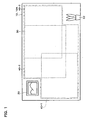
- FIG. 1 A schematic illustrative view of projection areas in accordance with an example of this embodiment is shown in Fig. 1 .
- a living room in particular is a location that is used by a plurality of members of the family, the positions of the picture 20 and the decorative plant 22 often change, making it difficult to fix a projection area.
- the living room and the kitchen are integrated into a single room, it would be convenient to project a TV image on the wall of the living room most of the time, but project the image of a recipe on the wall of the kitchen while cooking.
- This embodiment of the invention performs edge detection by using a CCD sensor to sense the projection target area 10, determines a plurality of projection areas 40-1 to 40-3 that satisfy a predetermined aspect ratio, determines one projection area based on user selection, and uses that projection area to project the image.
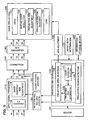
- FIG. 2 A functional block diagram of a projection-type image display system within a liquid-crystal projector in accordance with an example of this embodiment is shown in Fig. 2 .
- the projection-type image display system comprises a sensor 60, an input signal processing section 110, a correction section 120, a D/A converter section 180, an image projection section 190, a projection-area/pixel-area associating section 130, a projection area determination section 140, a calibration signal generation section 150, a lens adjustment section 160, and an aspect ratio determination section 132.
- the input signal processing section 110 converts an R1 signal, a G1 signal, and a B1 signal (which form RGB signals in analog form that is a type of input image information that is input from a personal computer (PC) or the like) into an R2 signal, a G2 signal, and a B2 signal in digital form.
- R1 signal a G1 signal
- B1 signal which form RGB signals in analog form that is a type of input image information that is input from a personal computer (PC) or the like
- the input signal processing section 110 comprises an A/D converter section 112 that performs this analog-to-digital conversion and an image position/size adjustment section 114 that is part of adjustment means for adjusting the position and size of an image.
- A/D converter section 112 and the D/A converter section 180 are not necessary if only RGB signals in digital format are used in the projection-type image display system.
- the calibration signal generation section 150 generates an R2 signal, a G2 signal, and a B2 signal in digital format that are used for displaying a calibration image.
- the liquid-crystal projector By generating the calibration signals within the liquid-crystal projector in this manner, it is possible for the liquid-crystal projector itself to perform the calibration, without having to input calibration signals to the liquid-crystal projector from an external input device such as a PC. Note that the configuration could also be such that the calibration signal generation section 150 is not provided and the calibration image signals are input from a PC or the like.
- the correction section 120 outputs an R3 signal, a G3 signal, and a B3 signal having a color temperature that has been corrected on the basis of a standard setting for the liquid-crystal projector, based on the R2 signal, G2 signal, and B2 signal from the input signal processing section 110 or the lens adjustment section 160.
- the D/A converter section 180 converts the R3 signal, G3 signal, and B3 signal from the correction section 120 into an R4 signal, a G4 signal, and a B4 signal in analog format.
- the image projection section 190 comprises a drive section 191, a spatial light modulator 192, a projection size adjustment section 193, a projection direction adjustment section 194, and a lens 195.
- the drive section 191 drives the spatial light modulator 192, based on the R4 signal, G4 signal, and B4 signal from the D/A converter section 180.
- the image projection section 190 projects light from a light source through the spatial light modulator 192 and the lens 195.
- the projection area determination section 140 comprising a projection area selection section 142, a projectable area determination section 144, an edge detection section 146, and a projection region detection section 148 is further provided in the liquid-crystal projector.
- the projection region detection section 148 detects the region of the projection target area 10 (hereinafter called a projection region 10A), based on sensing information expressed as XYZ values from the sensor 60, which is a sensing means that senses the projection target area 10.
- XYZ values are a type of device-independent colors under an international standard determined by the Commission Internationale de l'Eclairage (CIE).
- the projection target area 10 and the projection region 10A are shown to be the same size in Fig. 1 , to facilitate the description.
- the projection region 10A is a region on the projection target area 10 that is illuminated by the projection light.
- the edge detection section 146 performs edge detection, based on the XYZ values of the projection region 10A on the projection target area 10, and outputs detection information.
- the projectable area determination section 144 identifies projection areas 40-1 to 40-3 within the projection region 10A of the projection target area 10 which have no obstructions such as the picture 20 and which are of at least a fixed size that satisfies the aspect ratio, based on the detection information and a predetermined aspect ratio (such as 16:9 or 4:3) from the aspect ratio determination section 132.
- a representative three projection areas 40-1 to 40-3 are shown, to simplify the description, but in practice a larger number of the projection areas could be obtained. If only one projection area can be obtained, that is selected.
- the projectable area determination section 144 detects that a portion bounded by the outermost boundary lines of the projection areas is a projectable area 30.
- the projection area selection section 142 selects one projection area, based on a selection indication from the user (such as an indication by a remote controller of the liquid-crystal projector), for selecting one projection area from the plurality of projection areas 40-1 to 40-3 comprised within the projectable area 30.
- the lens adjustment section 160 that is part of the adjustment means outputs projection size control information to the projection size adjustment section 193, to adjust the zoom ratio of the lens 195 in such a manner that an image is projected onto the projection area that has been selected by the projection area selection section 142.
- the projection size adjustment section 193 adjusts the projection size by adjusting the zoom ratio of the lens 195, based on that projection size control information.
- the projection-area/pixel-area associating section 130 that is part of the adjustment means determines the association between the projection area within the projection region 10A on the projection target area 10 and the pixel area of the spatial light modulator 192, based on the projection region 10A on the projection target area 10 that was detected by the projection region detection section 148 and the projection area selected by the projection area selection section 142. Specifically, the projection-area/pixel-area associating section 130 obtains the ratio between the projection region 10A on the projection target area 10 and the pixel area of the spatial light modulator 192.
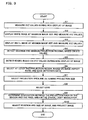
- FIG. 3 A flowchart of the sequence of image projection in accordance with an example of this embodiment is shown in Fig. 3 .
- the sensor 60 senses the projection target area 10 in a state in which there is no image displayed, in other words, in a state in which nothing is displayed or a completely black image is displayed, and measures the XYZ values of each pixel of that image (step S1).
- the lens adjustment section 160 outputs projection size control information for adjusting the zoom ratio of the lens 195 so as to maximize the image size, to the projection size adjustment section 193.
- the calibration signal generation section 150 generates calibration signals (R2, G2, B2) in such a manner that a full-screen white image is displayed.
- the thus-configured liquid-crystal projector displays the white image at the maximum image size and the sensor 60 measures the XYZ values of each pixel of the white image displayed on the projection target area 10 (in other words, each pixel within the sensor 60 that outputs measured values of that white image) (step S2).
- the lens adjustment section 160 outputs projection size control information for adjusting the zoom ratio of the lens 195 so as to minimize the image size, to the projection size adjustment section 193.
- the calibration signal generation section 150 again generates calibration signals (R2, G2, B2) in such a manner that a full-screen white image is displayed.
- the thus-configured liquid-crystal projector displays the white image at the minimum image size and the sensor 60 measures the XYZ values of each pixel of the white image displayed on the projection target area 10 (step S3).
- the projection region detection section 148 detects the maximum and minimum projection region 10A, based on the difference between the XYZ values measured when nothing was displayed and the XYZ values measured at the maximum size, and the difference between the XYZ values measured when nothing was displayed and the XYZ values measured at the minimum size (step S4).
- a pixel having a difference of at least 5cd/m 2 could be considered to be a pixel comprised within the projection region 10A of the projection target area 10, by way of example.
- sensing information XYZ values
- the edge detection section 146 executes edge detection processing based on the XYZ values measured when nothing was displayed (step S5).
- the projectable area determination section 144 determines the projectable area 30 (that is, an area comprising at least one of the projection areas), based on the image aspect ratio from the aspect ratio determination section 132 and the edge detection data from the edge detection section 146 (step S6). More specifically, the projectable area determination section 144 detects edge detection data from the top left of that region to the bottom right thereof, and specifies the maximum area that satisfies a desired aspect ration (that is, one of the projection areas). If there is a many-sided area such as the projectable area 30 shown in Fig. 1 , by way of example, a plurality of projection areas 40-1 to 40-3 is selected.
- the projection area determination section 140 outputs information indicating the plurality of projection areas 40-1 to 40-3 selected by the projectable area determination section 144 to the input signal processing section 110, and the image projection section 190 projects to the user a selection image enabling the selection of one projection area from that plurality of projection areas 40-1 to 40-3.
- the input signal processing section 110 could have stored therein image information for generating the selection image.
- the projection area selection section 142 selects one projection area from the plurality of projection areas 40-1 to 40-3, based on a predetermined criterion (such as the uppermost, lowermost, leftmost, or rightmost) or the user's indication, and determines a lens zoom ratio that ensures that the projection region 10A comprises the selected projection area and also the projection region 10A is of the minimum projection size (step S7).
- a predetermined criterion such as the uppermost, lowermost, leftmost, or rightmost
- the projection size need not be the minimum.
- the lens adjustment section 160 generates projection size control information that ensures that zoom ratio, and the projection size adjustment section 193 adjusts the zoom ratio of the lens 195, based on that projection size control information (step S8).
- the projection-area/pixel-area associating section 130 determines the association between the projection area at that zoom ratio and the pixel area of the spatial light modulator 192 (step S9).
- the image could be resized so that the entire region of the image represented by the image signal is projected into the selected projection area, or the image could be trimmed for projection into the selected projection area.
- the image position/size adjustment section 114 adjusts the digitally converted input image signal in such a manner as to adjust the position and size of the image, based on this association, and outputs digital signals (R2, G2, B2).
- the correction section 120 also performs adjustments such as color temperature adjustments on these digital signals (R2, G2, B2), and the D/A converter section 180 outputs analog signals (R4, G4, B4) that have been converted from the digital signals.
- the drive section 191 drives the spatial light modulator 192 on the basis of the analog signals (R4, G4, B4), and the projection size adjustment section 193 adjusts the zoom ratio of the lens 195.
- the image projection section 190 adjusts the position and size of the image and projects the image onto the projection area (step S10).
- this embodiment makes it possible for a projection-type image display system to automatically select the projectable area 30 in which there are no obstructions (such as desks or members of the audience), so that the user can change the projection area easily.
- the user would usually project images on a wall surface of the living room, but might also want to project an image onto a wall surface in the kitchen when cooking.
- this embodiment makes it easy fro the user to switch between projection into the living room and projection into the kitchen.
- a right-handed presenter would find it easier to use an indicator rod with an image that is displayed on the right side, as seen from the audience, whereas a left-handed presenter would find it easier to use an indicator rod with an image displayed on the left side.
- this embodiment makes it possible to project an image at a position preferred by the user, without the user having to adjust the projection position manually.
- this embodiment also makes it possible for the projection-type image display system to adjust the projection size automatically, it enables a simpler changing of the projection position, without requiring the user to adjust the projection size.
- this embodiment makes it possible for the projection-type image display system to automatically determine the association between the projection region 10A on the projection target area 10 and the pixel area of the spatial light modulator 192, it enables the projection of an image at the appropriate image size at the appropriate location.
- FIG. 4 A block diagram of the hardware of a projection-type image display system within a liquid-crystal projector in accordance with an example of this embodiment is shown in Fig. 4 .
- the configuration could be implemented by an A/D converter 930 or the like as the A/D converter section 112; a D/A converter 940 or the like as the D/A converter section 180; a ROM 960 or the like in which is stored a liquid-crystal light bulb driver as the drive section 191; a liquid crystal panel 920 and liquid crystal light valves as the spatial light modulator 192; an image processing circuit 970 and a CPU 910 or the like as the projector color converter section 120, the projection area selection section 142, the projectable area determination section 144, the edge detection section 146, the projection region detection section 148, the projection-area/pixel-area associating section 130, the aspect ratio determination section 132, and the lens adjustment section 160; RAM 950 or the like as the calibration signal generation section 150; a generic lens zooming mechanism or the like as the projection size adjustment section 193; a generic direction control mechanism as the projection direction adjustment section 194; and a sensor that is capable of extracting XYZ values from a multi-pixel
- these functions could be implemented by a computer within the liquid-crystal projector reading out a program from an information storage medium 300.
- the information storage medium 300 could be a CD-ROM, DVD-ROM, ROM, RAM, or HDD, by way of example, and the method of reading the program therefrom could be a direct method or an indirect method.
- the projectable area 30 may be determined based on information other than the edge detection information although the aforementioned embodiment has been described as to the projectable area determination section 144 determining the projectable area 30 based on the edge detection information in the sensed image from the edge detection section 146.
- the projectable area determination section 144 may determine the projectable area 30 based on the color distribution in the sensed image.
- the projectable area 30 can be selected by detecting the distribution of XYZ values representing colors, for example, since, in Fig. 1 , the XYZ values relating to the obstruction such as the decorative plant 22 or the like in the sensed image are different from the XYZ values in the projectable area 30.
- the technique of selecting the projectable area 30 based on the color distribution will be described below.
- Fig. 5 is a functional block diagram of a projection-type image display system in a liquid-crystal projector according to an example of this embodiment.
- the edge detection section 146 is replaced by a color-distribution detection section 147 which is designed to output detection information indicating the color distribution in the sensed image (which may be the whole or part of the sensed image) from the sensor 60 while the projectable area determination section 144 is replaced by a projectable area determination section 145.
- the color-distribution detection section 147 detects the color distribution in the projection region 10A based on the sensing information (XYZ values) relating to a portion corresponding to a projection region having the maximum image size in the sensed image when nothing is displayed.
- the color-distribution detection section 147 generates the histogram (or frequency distribution) of XYZ values for a predetermined image processing unit (a pixel block constructed by a fixed number of pixels along the horizontal and vertical directions, one pixel or the like).
- the color-distribution detection section 147 detects a range of X-value having upper frequency (XP1 to XP2) in the histogram of X value. Similarly, the color-distribution detection section 147 detects a range of Y-value having upper frequency (YP1 to YP2) and a range of Z-value having upper frequency (ZP1 to ZP2). These ranges are optional. For example, they may be identical with one another or different from one another.
- the color-distribution detection section 147 then outputs these pieces of color-distribution information (XP1 to XP2, YP1 to YP2 and ZP1 to ZP2) toward the projectable area determination section 145.
- the projectable area determination section 145 determines the projectable area 30, based on an aspect ratio of image from the aspect ratio determination section 132 and the information of detected color distribution from the color-distribution detection section 147.
- the projectable area determination section 145 selects an area AX having an X-value in the range of X-value (XP1 to XP2) from the color-distribution detection section 147 based on the sensing information relating to a portion corresponding to the projection area 10A in the sensed image.
- the sensing information has an ordinate position, an abscissa position, X-value, Y-value and Z-value for each coordinate position. Therefore, the projectable area determination section 145 can select the area AX since it can detect the ordinate and abscissa positions in the coordinates having the X-value which can be used as a searching key.
- areas AY and AZ for Y and Z values may be selected.
- the projectable area determination section 145 selects the area AX having the X-value in the range of X-value (XP1 to XP2), the area AY having the Y-value in the range of X-value (YP1 to YP2) and the area AZ having the Z-value in the range of Z-value (ZP1 to ZP2) in addition to an area AA (the projectable area 30 in Fig. 1 , for example) in which the areas AX, AY and AZ overlap each other.
- an area AA the projectable area 30 in Fig. 1 , for example
- the projectable area 30 can be selected.
- the remaining procedure portion may be accomplished by various steps after the above-mentioned step S6 in FIG. 3 .
- the liquid-crystal projector can select the projection area as a portion satisfying the aspect ratio among an area which has the same color and is not been influenced by the environment (due to the fluorescent lamp or the like) or is influenced by the environment, even if part of the projection target area 10 has been influenced by that environment.
- the liquid-crystal projector according to this embodiment can perform the processing at a higher speed and in a more efficient manner since the edge detection can be omitted by adopting the technique based on the color distribution.
- the technique of detecting the color distribution is not limited to the aforementioned technique.
- the range of XYZ values may be determined by calculating with different coefficient values or by using a certain function.
- the indexes for detecting the color distribution may be in the form of RGB values, rather than the XYZ values.
- the liquid-crystal projector may perform the following process.
- the liquid-crystal projector can determine the aforementioned projection area by repeatedly projecting and imaging points or lines indicative of four corners in the image while narrowing the projection range and detecting these points or lines through the sensor 60 before the four corners in the sensed image are associated with the coordinates of the four corners in the spatial light modulator 192.
- the edge detection may be carried out by use of sensing information indicative of differences between the XYZ values of the sensed image relating to the monochromatic white-colored calibration image and the XYZ values of the sensed image relating to the monochromatic black-colored calibration image although this embodiment has been described as to the single black-colored calibration image used to perform the edge detection or the like by the liquid-crystal projector.
- the liquid-crystal projector can perform the color-distribution detection and the like while correcting such difference.
- the configuration could be such that the lens adjustment section 160 outputs projection direction control information for controlling the projection direction to the projection direction adjustment section 194, instead of the projection size.
- the projection size could also be fixed so that only the projection direction is changed. This would enable simple changing of the projection position.
- the selection of the projection area by the user could be done by a button on the projector itself of by a remote-control action, and the user could use a physical indication or a verbal indication.
- the maximum projectable area 30 was obtained initially by selecting at least one projection area that satisfies the aspect ratio, but at least one projection area that satisfies the aspect ratio could be selected within the projectable area 30 after the obstruction-free projectable area 30 has been obtained.
- the projection area in the above-described embodiment was a rectangle, but a shape other than a rectangle can equally well be used as the projection area, such as a circle.
- the image projection processing of Fig. 3 could be repeated at a predetermined timing (such as every predetermined time, or whenever the presenter changes).
- the projection area could be determined from the positions of obstructions.
- the projection-type image display system of this embodiment was described above as being applied to a liquid-crystal projector but it can also be applied to various other types of projection-type display systems such as a projector using a digital micromirror device (DMD) as the spatial light modulator.
- DMD digital micromirror device
- the projector is not limited to a front-projection type; it could equally well be a rear-projection type of projector.
- the present invention is also effective for projecting images in commercial applications such as meeting rooms, medical facilities, advertisement locations, educational locations, cinemas, and exhibition halls.
- the above-described functions of the projection-type image display system could be implemented by the liquid-crystal projector itself, by way of example, or they could be implemented by processing distributed between a plurality of processing devices (such as the liquid-crystal projector and a PC).
Description
- The present invention relates to a projector, an information storage medium, and an image projection method that enable changes in projection position.
- Projection-type image display systems such as liquid-crystal projectors are used in various situations such as classrooms, cinemas, meeting rooms, exhibition halls, and domestic living rooms.
- When a liquid-crystal projector or the like is used to project an image, any obstruction between the image projection section and the projection surface will generate a shadow caused by the projection light hitting the obstruction, and the obstruction itself could block the field of view, making the image difficult to see.
- In a domestic living room, for example, the liquid-crystal projector would not only be used by the user, but also by the family of that user. For that reason, even if the user has reserved a large area of a wall surface as a projection area, other members of the family could dispose furniture or decorative plants on that wall surface, or the user could cover part of the projection area with furniture without thinking.
- Similarly, when product introduction images or advertising images are projected in an exhibition hall or the like, people could enter an area within the projection area unexpectedly, making the images difficult to see.
- In such a case, it is usual for the user to move the liquid-crystal projector or change the projection direction of the liquid-crystal projector, to project an image that avoids obstructions, but moving the liquid-crystal projector or changing the projection direction thereof is labor-intensive, and it also necessitates re-calibration.
- When a liquid-crystal projector is employed to project an image, the user would also want to project an image on a projection area selected by the user on the basis of the circumstances during the projection.
- If the living room and kitchen are integrated into the same room, the user would usually project images on a wall surface of the living room, but might also want to project an image onto a wall surface in the kitchen when cooking.
- During a presentation, a right-handed presenter would find it easier to use an indicator rod with an image that is displayed on the right side, as seen from the audience, whereas a left-handed presenter would find it easier to use an indicator rod with an image displayed on the left side.
- In such a case, it would be preferable to change the projection position of the image in order to give a more effective presentation, but it would be time-consuming for the presenter to adjust the projection position of the projector manually and perform recalibration.
-
US 6,002,505 A discloses a laser projector including a safety circuit for preventing a person in between the projector and the projection screen to be irradiated by the laser. To this end, the known projector comprises sensing means allowing to detect an object between the projection screen and the projector. If an object is detected to projector is switched to a second mode in which the projector is either switched off or in which the laser is blanked as it sweeps the area in which the object has been deetcted. In the first case, no image is projected and in the second case, part of the image is projected and the remaining part is blanked to appear like a shadow of the object. Hence, part of the image can be seen at best. - It is an object of the present invention to provide a projector, an information storage medium, and an image projection method that make it possible to change the projection position in a simpler manner.
- This object is achieved by a projector as claimed in
claim 1, an information storage medium as claimed inclaim 6, and an image projection method as claimed in claim 11. - Since the present invention makes it possible for the projector to automatically determine a projectable area that does not contain obstructions (such as desks or members of the audience), it enables the user to change the projection position easily.
- Preferably, the image projection means adjusts a projection size so that an image is projected on the projection area. Since this makes it possible for a projector to adjust the projection size automatically, the user can change the projection position in a simpler manner, without having to adjust the projection size.
- In particular, it is possible to increase the brightness value of the image and display a brighter image than in a case that an image is displayed in the maximum projection size, by adjusting the zoom ratio of a projection lens in such a manner that the projection area for the projected image becomes a minimum size including the selected area.
- Controlling a projection direction in such a manner that an image is projected onto the projection area makes it possible to adjust the projection direction automatically, so that the user can change the projection position in a simpler manner, without having to adjust the projection direction.
- Repeating the sensing and outputting the detection information at a predetermined timing and determining the projectable area anew, based on the newest detection information makes it possible to automatically adjust the projection of the image into an obstruction-free projection area if the position of an obstruction changes (specifically if the audience should intrude into the projection area) by sensing and performing edge detection repeatedly at a predetermined timing, so that the user can change the projection position in a simpler manner.
-
-
Fig. 1 is a schematic illustrative view of projection areas in accordance with an example of this embodiment; -
Fig. 2 is a functional block diagram of a projection-type image display system within a liquid-crystal projector in accordance with an example of this embodiment; -
Fig. 3 is a flowchart of the sequence of image projection in accordance with an example of this embodiment; -
Fig. 4 is a block diagram of the hardware of the projection-type image display system within the liquid-crystal projector in accordance with an example of this embodiment; and -
Fig. 5 is a functional block diagram of a projection-type image display system within a liquid-crystal projector in accordance with an example of this embodiment. - The present invention is described below, taking as an example the application thereof to a projection-type image display system that uses a liquid-crystal projector, with reference to the accompanying figures. Note that the embodiment described below does not in any way limit the scope of the invention as laid out in the claims herein. In addition, the entirety of the configuration described with reference to this embodiment is not limited to being essential structural components of the present invention.
- The description below concerns an example in which a liquid-crystal projector is disposed in a domestic living room to project an image onto a wall.
- A schematic illustrative view of projection areas in accordance with an example of this embodiment is shown in
Fig. 1 . - When a wall surface is used as a projection target area 10 for the projection of an image, the presence of obstructions such as a
picture 20 or adecorative plant 22 causes shadows in those portions, making it impossible to project the image suitably. - Since a living room in particular is a location that is used by a plurality of members of the family, the positions of the
picture 20 and thedecorative plant 22 often change, making it difficult to fix a projection area. - Furthermore, if the living room and the kitchen are integrated into a single room, it would be convenient to project a TV image on the wall of the living room most of the time, but project the image of a recipe on the wall of the kitchen while cooking.
- This embodiment of the invention performs edge detection by using a CCD sensor to sense the projection target area 10, determines a plurality of projection areas 40-1 to 40-3 that satisfy a predetermined aspect ratio, determines one projection area based on user selection, and uses that projection area to project the image.
- The employment of this method makes it easy to change the projection position, without requiring the user to move the liquid-crystal projector or change the projection position or projection direction manually.
- The description now turns to the functional blocks of a projection-type image display system that is installed in a liquid-crystal projector, in order to implement this function.
- A functional block diagram of a projection-type image display system within a liquid-crystal projector in accordance with an example of this embodiment is shown in
Fig. 2 . - The projection-type image display system comprises a
sensor 60, an inputsignal processing section 110, acorrection section 120, a D/A converter section 180, animage projection section 190, a projection-area/pixel-area associating section 130, a projectionarea determination section 140, a calibrationsignal generation section 150, alens adjustment section 160, and an aspectratio determination section 132. - The input
signal processing section 110 converts an R1 signal, a G1 signal, and a B1 signal (which form RGB signals in analog form that is a type of input image information that is input from a personal computer (PC) or the like) into an R2 signal, a G2 signal, and a B2 signal in digital form. - The input
signal processing section 110 comprises an A/D converter section 112 that performs this analog-to-digital conversion and an image position/size adjustment section 114 that is part of adjustment means for adjusting the position and size of an image. - Note that the A/
D converter section 112 and the D/A converter section 180 are not necessary if only RGB signals in digital format are used in the projection-type image display system. - The calibration
signal generation section 150 generates an R2 signal, a G2 signal, and a B2 signal in digital format that are used for displaying a calibration image. - By generating the calibration signals within the liquid-crystal projector in this manner, it is possible for the liquid-crystal projector itself to perform the calibration, without having to input calibration signals to the liquid-crystal projector from an external input device such as a PC. Note that the configuration could also be such that the calibration
signal generation section 150 is not provided and the calibration image signals are input from a PC or the like. - The
correction section 120 outputs an R3 signal, a G3 signal, and a B3 signal having a color temperature that has been corrected on the basis of a standard setting for the liquid-crystal projector, based on the R2 signal, G2 signal, and B2 signal from the inputsignal processing section 110 or thelens adjustment section 160. - The D/
A converter section 180 converts the R3 signal, G3 signal, and B3 signal from thecorrection section 120 into an R4 signal, a G4 signal, and a B4 signal in analog format. - The
image projection section 190 comprises adrive section 191, aspatial light modulator 192, a projectionsize adjustment section 193, a projectiondirection adjustment section 194, and alens 195. - The
drive section 191 drives thespatial light modulator 192, based on the R4 signal, G4 signal, and B4 signal from the D/A converter section 180. Theimage projection section 190 projects light from a light source through thespatial light modulator 192 and thelens 195. - With this embodiment, the projection
area determination section 140 comprising a projectionarea selection section 142, a projectablearea determination section 144, anedge detection section 146, and a projectionregion detection section 148 is further provided in the liquid-crystal projector. - The projection
region detection section 148 detects the region of the projection target area 10 (hereinafter called a projection region 10A), based on sensing information expressed as XYZ values from thesensor 60, which is a sensing means that senses the projection target area 10. Note that is this case, XYZ values are a type of device-independent colors under an international standard determined by the Commission Internationale de l'Eclairage (CIE). - Note that the projection target area 10 and the projection region 10A are shown to be the same size in
Fig. 1 , to facilitate the description. In this case, the projection region 10A is a region on the projection target area 10 that is illuminated by the projection light. - The
edge detection section 146 performs edge detection, based on the XYZ values of the projection region 10A on the projection target area 10, and outputs detection information. - The projectable
area determination section 144 identifies projection areas 40-1 to 40-3 within the projection region 10A of the projection target area 10 which have no obstructions such as thepicture 20 and which are of at least a fixed size that satisfies the aspect ratio, based on the detection information and a predetermined aspect ratio (such as 16:9 or 4:3) from the aspectratio determination section 132. InFig. 1 , a representative three projection areas 40-1 to 40-3 are shown, to simplify the description, but in practice a larger number of the projection areas could be obtained. If only one projection area can be obtained, that is selected. The projectablearea determination section 144 detects that a portion bounded by the outermost boundary lines of the projection areas is aprojectable area 30. - Note that a plurality of the
projectable areas 30 could be detected if the projection areas do not overlap. - The projection
area selection section 142 selects one projection area, based on a selection indication from the user (such as an indication by a remote controller of the liquid-crystal projector), for selecting one projection area from the plurality of projection areas 40-1 to 40-3 comprised within theprojectable area 30. - The
lens adjustment section 160 that is part of the adjustment means outputs projection size control information to the projectionsize adjustment section 193, to adjust the zoom ratio of thelens 195 in such a manner that an image is projected onto the projection area that has been selected by the projectionarea selection section 142. - The projection
size adjustment section 193 adjusts the projection size by adjusting the zoom ratio of thelens 195, based on that projection size control information. - The projection-area/pixel-
area associating section 130 that is part of the adjustment means determines the association between the projection area within the projection region 10A on the projection target area 10 and the pixel area of the spatiallight modulator 192, based on the projection region 10A on the projection target area 10 that was detected by the projectionregion detection section 148 and the projection area selected by the projectionarea selection section 142. Specifically, the projection-area/pixel-area associating section 130 obtains the ratio between the projection region 10A on the projection target area 10 and the pixel area of the spatiallight modulator 192. - The description now turns to the flow of image processing using these components, with reference to a flowchart.
- A flowchart of the sequence of image projection in accordance with an example of this embodiment is shown in
Fig. 3 . - First of all, the
sensor 60 senses the projection target area 10 in a state in which there is no image displayed, in other words, in a state in which nothing is displayed or a completely black image is displayed, and measures the XYZ values of each pixel of that image (step S1). - The
lens adjustment section 160 outputs projection size control information for adjusting the zoom ratio of thelens 195 so as to maximize the image size, to the projectionsize adjustment section 193. The calibrationsignal generation section 150 generates calibration signals (R2, G2, B2) in such a manner that a full-screen white image is displayed. - The thus-configured liquid-crystal projector displays the white image at the maximum image size and the
sensor 60 measures the XYZ values of each pixel of the white image displayed on the projection target area 10 (in other words, each pixel within thesensor 60 that outputs measured values of that white image) (step S2). - In a similar manner, the
lens adjustment section 160 outputs projection size control information for adjusting the zoom ratio of thelens 195 so as to minimize the image size, to the projectionsize adjustment section 193. The calibrationsignal generation section 150 again generates calibration signals (R2, G2, B2) in such a manner that a full-screen white image is displayed. - The thus-configured liquid-crystal projector displays the white image at the minimum image size and the
sensor 60 measures the XYZ values of each pixel of the white image displayed on the projection target area 10 (step S3). - The projection
region detection section 148 detects the maximum and minimum projection region 10A, based on the difference between the XYZ values measured when nothing was displayed and the XYZ values measured at the maximum size, and the difference between the XYZ values measured when nothing was displayed and the XYZ values measured at the minimum size (step S4). In this case, a pixel having a difference of at least 5cd/m2 could be considered to be a pixel comprised within the projection region 10A of the projection target area 10, by way of example. Note that instead of sensing information (XYZ values) obtained when the black calibration image is displayed, it is also possible to use sensing information for the projection region 10A on the projection target area 10 when nothing is displayed. - The
edge detection section 146 executes edge detection processing based on the XYZ values measured when nothing was displayed (step S5). - The projectable
area determination section 144 determines the projectable area 30 (that is, an area comprising at least one of the projection areas), based on the image aspect ratio from the aspectratio determination section 132 and the edge detection data from the edge detection section 146 (step S6). More specifically, the projectablearea determination section 144 detects edge detection data from the top left of that region to the bottom right thereof, and specifies the maximum area that satisfies a desired aspect ration (that is, one of the projection areas). If there is a many-sided area such as theprojectable area 30 shown inFig. 1 , by way of example, a plurality of projection areas 40-1 to 40-3 is selected. - The projection
area determination section 140 outputs information indicating the plurality of projection areas 40-1 to 40-3 selected by the projectablearea determination section 144 to the inputsignal processing section 110, and theimage projection section 190 projects to the user a selection image enabling the selection of one projection area from that plurality of projection areas 40-1 to 40-3. In this case, the inputsignal processing section 110 could have stored therein image information for generating the selection image. - The projection
area selection section 142 selects one projection area from the plurality of projection areas 40-1 to 40-3, based on a predetermined criterion (such as the uppermost, lowermost, leftmost, or rightmost) or the user's indication, and determines a lens zoom ratio that ensures that the projection region 10A comprises the selected projection area and also the projection region 10A is of the minimum projection size (step S7). - Note that this use of the minimum projection size ensures that it is possible to increase the brightness in comparison with the maximum projection size. Of course the projection size need not be the minimum.
- The
lens adjustment section 160 generates projection size control information that ensures that zoom ratio, and the projectionsize adjustment section 193 adjusts the zoom ratio of thelens 195, based on that projection size control information (step S8). - The projection-area/pixel-
area associating section 130 determines the association between the projection area at that zoom ratio and the pixel area of the spatial light modulator 192 (step S9). In this case, the image could be resized so that the entire region of the image represented by the image signal is projected into the selected projection area, or the image could be trimmed for projection into the selected projection area. - The image position/
size adjustment section 114 adjusts the digitally converted input image signal in such a manner as to adjust the position and size of the image, based on this association, and outputs digital signals (R2, G2, B2). - The
correction section 120 also performs adjustments such as color temperature adjustments on these digital signals (R2, G2, B2), and the D/A converter section 180 outputs analog signals (R4, G4, B4) that have been converted from the digital signals. - The
drive section 191 drives the spatiallight modulator 192 on the basis of the analog signals (R4, G4, B4), and the projectionsize adjustment section 193 adjusts the zoom ratio of thelens 195. - In this manner, the
image projection section 190 adjusts the position and size of the image and projects the image onto the projection area (step S10). - As described above, this embodiment makes it possible for a projection-type image display system to automatically select the
projectable area 30 in which there are no obstructions (such as desks or members of the audience), so that the user can change the projection area easily. - If the living room and kitchen are integrated into the same room, for example, the user would usually project images on a wall surface of the living room, but might also want to project an image onto a wall surface in the kitchen when cooking.
- In such a case, this embodiment makes it easy fro the user to switch between projection into the living room and projection into the kitchen.
- During a presentation, a right-handed presenter would find it easier to use an indicator rod with an image that is displayed on the right side, as seen from the audience, whereas a left-handed presenter would find it easier to use an indicator rod with an image displayed on the left side.
- In such a case, this embodiment makes it possible to project an image at a position preferred by the user, without the user having to adjust the projection position manually.
- Since this embodiment also makes it possible for the projection-type image display system to adjust the projection size automatically, it enables a simpler changing of the projection position, without requiring the user to adjust the projection size.
- Furthermore, since this embodiment makes it possible for the projection-type image display system to automatically determine the association between the projection region 10A on the projection target area 10 and the pixel area of the spatial
light modulator 192, it enables the projection of an image at the appropriate image size at the appropriate location. - Note that the hardware described below by way of example can be used to implement the above described components.
- A block diagram of the hardware of a projection-type image display system within a liquid-crystal projector in accordance with an example of this embodiment is shown in
Fig. 4 . - For example, the configuration could be implemented by an A/
D converter 930 or the like as the A/D converter section 112; a D/A converter 940 or the like as the D/A converter section 180; aROM 960 or the like in which is stored a liquid-crystal light bulb driver as thedrive section 191; aliquid crystal panel 920 and liquid crystal light valves as the spatiallight modulator 192; animage processing circuit 970 and aCPU 910 or the like as the projectorcolor converter section 120, the projectionarea selection section 142, the projectablearea determination section 144, theedge detection section 146, the projectionregion detection section 148, the projection-area/pixel-area associating section 130, the aspectratio determination section 132, and thelens adjustment section 160;RAM 950 or the like as the calibrationsignal generation section 150; a generic lens zooming mechanism or the like as the projectionsize adjustment section 193; a generic direction control mechanism as the projectiondirection adjustment section 194; and a sensor that is capable of extracting XYZ values from a multi-pixel sensor such as a CCD sensor or CMOS sensor as thesensor 60. Note that these components can exchange information between themselves over asystem bus 980. Note also that these portions could be implemented in a hardware fashion by circuitry, or they could be implemented in a software fashion by drivers. - In addition, these functions could be implemented by a computer within the liquid-crystal projector reading out a program from an
information storage medium 300. - The
information storage medium 300 could be a CD-ROM, DVD-ROM, ROM, RAM, or HDD, by way of example, and the method of reading the program therefrom could be a direct method or an indirect method. - Instead of the
information storage medium 300, it is also possible to download a program that implements the above-described functions, from a host device over a network, in order to implement the above-described functions. - For example, the
projectable area 30 may be determined based on information other than the edge detection information although the aforementioned embodiment has been described as to the projectablearea determination section 144 determining theprojectable area 30 based on the edge detection information in the sensed image from theedge detection section 146. For example, the projectablearea determination section 144 may determine theprojectable area 30 based on the color distribution in the sensed image. - In other words, the
projectable area 30 can be selected by detecting the distribution of XYZ values representing colors, for example, since, inFig. 1 , the XYZ values relating to the obstruction such as thedecorative plant 22 or the like in the sensed image are different from the XYZ values in theprojectable area 30. The technique of selecting theprojectable area 30 based on the color distribution will be described below. -
Fig. 5 is a functional block diagram of a projection-type image display system in a liquid-crystal projector according to an example of this embodiment. - In this embodiment, the
edge detection section 146 is replaced by a color-distribution detection section 147 which is designed to output detection information indicating the color distribution in the sensed image (which may be the whole or part of the sensed image) from thesensor 60 while the projectablearea determination section 144 is replaced by a projectablearea determination section 145. - After the process in the projection region detection section 148 (step S4) described in connection with
Fig. 3 , the color-distribution detection section 147 detects the color distribution in the projection region 10A based on the sensing information (XYZ values) relating to a portion corresponding to a projection region having the maximum image size in the sensed image when nothing is displayed. - More particularly, the color-
distribution detection section 147 generates the histogram (or frequency distribution) of XYZ values for a predetermined image processing unit (a pixel block constructed by a fixed number of pixels along the horizontal and vertical directions, one pixel or the like). - And, the color-
distribution detection section 147 detects a range of X-value having upper frequency (XP1 to XP2) in the histogram of X value. Similarly, the color-distribution detection section 147 detects a range of Y-value having upper frequency (YP1 to YP2) and a range of Z-value having upper frequency (ZP1 to ZP2). These ranges are optional. For example, they may be identical with one another or different from one another. - The color-
distribution detection section 147 then outputs these pieces of color-distribution information (XP1 to XP2, YP1 to YP2 and ZP1 to ZP2) toward the projectablearea determination section 145. - The projectable
area determination section 145 determines theprojectable area 30, based on an aspect ratio of image from the aspectratio determination section 132 and the information of detected color distribution from the color-distribution detection section 147. - More particularly, the projectable
area determination section 145 selects an area AX having an X-value in the range of X-value (XP1 to XP2) from the color-distribution detection section 147 based on the sensing information relating to a portion corresponding to the projection area 10A in the sensed image. In addition, the sensing information has an ordinate position, an abscissa position, X-value, Y-value and Z-value for each coordinate position. Therefore, the projectablearea determination section 145 can select the area AX since it can detect the ordinate and abscissa positions in the coordinates having the X-value which can be used as a searching key. Similarly, areas AY and AZ for Y and Z values may be selected. - According to such a procedure, the projectable
area determination section 145 selects the area AX having the X-value in the range of X-value (XP1 to XP2), the area AY having the Y-value in the range of X-value (YP1 to YP2) and the area AZ having the Z-value in the range of Z-value (ZP1 to ZP2) in addition to an area AA (theprojectable area 30 inFig. 1 , for example) in which the areas AX, AY and AZ overlap each other. - In such a manner, the
projectable area 30 can be selected. The remaining procedure portion may be accomplished by various steps after the above-mentioned step S6 inFIG. 3 . - By adopting such a technique based on the color distribution, the liquid-crystal projector according to this embodiment can select the projection area as a portion satisfying the aspect ratio among an area which has the same color and is not been influenced by the environment (due to the fluorescent lamp or the like) or is influenced by the environment, even if part of the projection target area 10 has been influenced by that environment.
- The liquid-crystal projector according to this embodiment can perform the processing at a higher speed and in a more efficient manner since the edge detection can be omitted by adopting the technique based on the color distribution.
- However, the technique of detecting the color distribution is not limited to the aforementioned technique. For example, the range of XYZ values may be determined by calculating with different coefficient values or by using a certain function. Moreover, the indexes for detecting the color distribution may be in the form of RGB values, rather than the XYZ values.
- If part of the projection target area 10 is an empty space when the liquid-crystal projector is used outdoors or if part of the projection target area 10 is on a glass window which will not reflect the projected light from the liquid-crystal projector when it is used in a class room, the liquid-crystal projector may perform the following process.
- For example, if the liquid-crystal projector is to project a rectangular image, it can determine the aforementioned projection area by repeatedly projecting and imaging points or lines indicative of four corners in the image while narrowing the projection range and detecting these points or lines through the
sensor 60 before the four corners in the sensed image are associated with the coordinates of the four corners in the spatiallight modulator 192. - Moreover, the edge detection may be carried out by use of sensing information indicative of differences between the XYZ values of the sensed image relating to the monochromatic white-colored calibration image and the XYZ values of the sensed image relating to the monochromatic black-colored calibration image although this embodiment has been described as to the single black-colored calibration image used to perform the edge detection or the like by the liquid-crystal projector.
- In such a manner, even if the projection target area 10 includes areas of differently influenced environment, the liquid-crystal projector can perform the color-distribution detection and the like while correcting such difference.
- Further, for example, the configuration could be such that the
lens adjustment section 160 outputs projection direction control information for controlling the projection direction to the projectiondirection adjustment section 194, instead of the projection size. - This would make it possible to adjust the projection direction automatically, thus making it easy for the user to change the projection position without having to adjust the projection direction.
- The projection size could also be fixed so that only the projection direction is changed. This would enable simple changing of the projection position.
- In addition, the selection of the projection area by the user could be done by a button on the projector itself of by a remote-control action, and the user could use a physical indication or a verbal indication.
- In the above-described embodiment, the maximum
projectable area 30 was obtained initially by selecting at least one projection area that satisfies the aspect ratio, but at least one projection area that satisfies the aspect ratio could be selected within theprojectable area 30 after the obstruction-freeprojectable area 30 has been obtained. - It is also possible to perform parallax distortion correction or automatic focus adjustment during the projection.
- The projection area in the above-described embodiment was a rectangle, but a shape other than a rectangle can equally well be used as the projection area, such as a circle.
- Furthermore, the image projection processing of
Fig. 3 could be repeated at a predetermined timing (such as every predetermined time, or whenever the presenter changes). - Since this makes it possible to automatically adjust the image so that it is projected into an obstruction-free projection area, by performing the sensing and edge detection repeatedly at a predetermined timing if there is a change in the position of an obstruction or if more of the audience encroach into the projection area, the user can change the projection position in a simpler manner. In addition, the projection area could be determined from the positions of obstructions.
- The projection-type image display system of this embodiment was described above as being applied to a liquid-crystal projector but it can also be applied to various other types of projection-type display systems such as a projector using a digital micromirror device (DMD) as the spatial light modulator. Note that DMD is a trademark registered to Texas Instruments Inc. of the USA. In addition, the projector is not limited to a front-projection type; it could equally well be a rear-projection type of projector.
- Other than a domestic environment such as the above-described living room, the present invention is also effective for projecting images in commercial applications such as meeting rooms, medical facilities, advertisement locations, educational locations, cinemas, and exhibition halls.
- Note that the above-described functions of the projection-type image display system could be implemented by the liquid-crystal projector itself, by way of example, or they could be implemented by processing distributed between a plurality of processing devices (such as the liquid-crystal projector and a PC).
Claims (14)
- A projector comprising:image projection means (190) for projecting an image represented by input image information towards a projection area (40-1-40-3),sensing means (60) for sensing a projection target area (10) and outputting a sensed image of the projection target area (10);detection means (146,147) for performing edge detection or color-distribution detection based on the sensed image and outputting detection information which indicates an edge in the sensed image or color distribution in the sensed image; andprojectable area determination means (144,145) for determining, based on the detection information, a projectable area (30) within the projection target area (10) that is not obstructed by any obstruction (20,22) between the image projection means (190) and the projectable area (30);characterized byprojection area selection means (142) for selecting the projection area (40-1-40-3) within said projectable area (30), such that the image can be displayed entirely with its aspect ratio; andadjustment means (114) for adjusting the image projection means (190) by at least one of adjusting a projection size and adjusting a projection direction, in such a manner that the image is displayed in the selected projection area (40-1-40-3).
- The projector as defined by claim 1,
wherein the image projection means (190) has projection size adjustment means (193) adapted to adjust the projection size, and
wherein the adjustment means (114) is adapted to output projection size control information to the image projection means (190) so that an image is projected onto the projection area (40-1-40-3), the projection size control information being used for controlling the projection size adjustment means (193). - The projector as defined by claim 2,
wherein the projection size adjustment means (193) is adapted to adjust the lens zoom ratio for projecting an image in such a manner that a projection range for the projected image becomes a minimum size including the projection area (40-1-40-3) selected by the projection area selection means (142). - The projector as defined by claim 1,
wherein the image projection means (190) has projection direction adjustment means (194) for adjusting the projection direction, and
wherein the adjustment means (114) is adapted to output projection direction control information to the image projection means (190) in such a manner that an image is projected on the projection area (40-1-40-3), the projection direction control information controlling the projection direction adjustment means (194). - The projector as defined by claim 1,
wherein the sensing means (60) is adapted to repeat the sensing and to output the detection information at a predetermined timing, and
wherein the projectable area determination means (144,145) is adapted to determine the projectable area (30) anew, based on the newest detection information. - An information storage medium which stores a computer-readable program causing a computer to function as:image projection means (190) for projecting an image represented by input image information towards a projection area (40-1-40-3),sensing means (60) for sensing a projection target area (10) and outputting a sensed image of the projection target area (10);detection means (146,147) for performing edge detection or color-distribution detection based on the sensed image and outputting detection information which indicates an edge in the sensed image or color distribution in the sensed image; andprojectable area determination means (144,145) for determining, based on the detection information, a projectable area (30) within the projection target area (10) that is not obstructed by any obstruction (20,22) between the image projection means (190) and the projectable area (30);characterized byprojection area selection means (142) for selecting the projection area (40-1-40-3) within said projectable area (30), such that the image can be displayed entirely with its aspect ratio;adjustment means (114) arranged to adjust the image projection means (190) by at least one of adjusting a projection size and adjusting a projection direction, in such a manner that the image is displayed in the selected projection area (40-1-40-3).
- The information storage medium as defined by claim 6,
wherein the image projection means (190) has projection size adjustment means (193) which is adapted to adjust the projection size, and
wherein the adjustment means (114) is adapted to output projection size control information to the image projection means (190) so that an image is projected onto the projection area (40-1-40-3), the projection size control information being used for controlling the projection size adjustment means (193). - The information storage medium as defined by claim 7,
wherein the projection size adjustment means (193) is adapted to adjust the lens zoom ratio for projecting an image in such a manner that a projection range for the projected image becomes a minimum size including the projection area (40-1-40-3) selected by the projection area selection means (142). - The information storage medium as defined by claim 6,
wherein the image projection means (190) has projection direction adjustment means (194) for adjusting the projection direction, and
wherein the adjustment means (114) is adapted to output projection direction control information to the image projection means (190) in such a manner that an image is projected on the projection area (40-1-40-3), the projection direction control information controlling the projection direction adjustment means (194). - The information storage medium as defined by claim 7,
wherein the sensing means (60) is adapted to repeat the sensing and to output the detection information at a predetermined timing, and
wherein the projectable area determination means (144,145) is adapted to determine the projectable area (30) anew, based on newest detection information. - An image projection method for projecting an image represented by input image information towards a projection area (40-1-40-3) comprising:sensing a projection target area (10) and outputting a sensed image of the projection target area (10);performing edge detection or color-distribution detection based on the sensed image and outputting detection information which indicates an edge in the sensed image or color distribution in the sensed image; anddetermining, based on the detection information, a projectable area (30) within the projection target area (10) that is not obstructed by any obstruction (20,22) between the image projection means (190) and the projectable area (30);characterized byselecting the projection area (40-1-40-3) within said projectable area (30), such that the image can be displayed entirely with its aspect ratio;adjusting the image projection means (190) by at least one of adjusting a projection size and adjusting a projection direction, in such a manner that the image is displayed in the selected projection area; andprojecting the image towards the projection area (40-1-40-3), based on the input image information.
- The image projection method as defined by claim 11, further comprising:controlling the image projection means (190) to adjust the projection size so that an image is projected on the projection area (40-1-40-3).
- The image projection method as defined by claim 11, further comprising:controlling the image projection means (190) to control the projection direction in such a manner that an image is projected onto the projection area (40-1-40-3).
- The image projection method as defined by claim 11, further comprising:repeating the sensing and outputting the detection information at a predetermined timing; anddetermining the projectable area (30) anew, based on the newest detection information.
Priority Applications (1)
| Application Number | Priority Date | Filing Date | Title |
|---|---|---|---|
| EP07017286A EP1855471B1 (en) | 2002-05-20 | 2003-05-20 | Projector, information storage medium, and image projection method |
Applications Claiming Priority (4)
| Application Number | Priority Date | Filing Date | Title |
|---|---|---|---|
| JP2002144671 | 2002-05-20 | ||
| JP2002144671 | 2002-05-20 | ||
| JP2003127027 | 2003-05-02 | ||
| JP2003127027A JP4009851B2 (en) | 2002-05-20 | 2003-05-02 | Projection-type image display system, projector, program, information storage medium, and image projection method |
Related Child Applications (1)
| Application Number | Title | Priority Date | Filing Date |
|---|---|---|---|
| EP07017286A Division EP1855471B1 (en) | 2002-05-20 | 2003-05-20 | Projector, information storage medium, and image projection method |
Publications (3)
| Publication Number | Publication Date |
|---|---|
| EP1365584A2 EP1365584A2 (en) | 2003-11-26 |
| EP1365584A3 EP1365584A3 (en) | 2004-11-10 |
| EP1365584B1 true EP1365584B1 (en) | 2008-08-20 |
Family
ID=29405342
Family Applications (2)
| Application Number | Title | Priority Date | Filing Date |
|---|---|---|---|
| EP07017286A Expired - Lifetime EP1855471B1 (en) | 2002-05-20 | 2003-05-20 | Projector, information storage medium, and image projection method |
| EP03011064A Expired - Fee Related EP1365584B1 (en) | 2002-05-20 | 2003-05-20 | Projector-type image display system, projector, information storage medium and image projection method |
Family Applications Before (1)
| Application Number | Title | Priority Date | Filing Date |
|---|---|---|---|
| EP07017286A Expired - Lifetime EP1855471B1 (en) | 2002-05-20 | 2003-05-20 | Projector, information storage medium, and image projection method |
Country Status (5)
| Country | Link |
|---|---|
| US (2) | US7626600B2 (en) |
| EP (2) | EP1855471B1 (en) |
| JP (1) | JP4009851B2 (en) |
| CN (1) | CN1212561C (en) |
| DE (2) | DE60335311D1 (en) |
Cited By (4)
| Publication number | Priority date | Publication date | Assignee | Title |
|---|---|---|---|---|
| US7891818B2 (en) | 2006-12-12 | 2011-02-22 | Evans & Sutherland Computer Corporation | System and method for aligning RGB light in a single modulator projector |
| US8077378B1 (en) | 2008-11-12 | 2011-12-13 | Evans & Sutherland Computer Corporation | Calibration system and method for light modulation device |
| US8358317B2 (en) | 2008-05-23 | 2013-01-22 | Evans & Sutherland Computer Corporation | System and method for displaying a planar image on a curved surface |
| US8702248B1 (en) | 2008-06-11 | 2014-04-22 | Evans & Sutherland Computer Corporation | Projection method for reducing interpixel gaps on a viewing surface |
Families Citing this family (66)
| Publication number | Priority date | Publication date | Assignee | Title |
|---|---|---|---|---|
| JPH1145154A (en) * | 1997-07-28 | 1999-02-16 | Melco:Kk | Mouse |
| JP4009851B2 (en) * | 2002-05-20 | 2007-11-21 | セイコーエプソン株式会社 | Projection-type image display system, projector, program, information storage medium, and image projection method |
| JP4055010B2 (en) | 2003-09-26 | 2008-03-05 | セイコーエプソン株式会社 | Image processing system, projector, program, information storage medium, and image processing method |
| US6984039B2 (en) | 2003-12-01 | 2006-01-10 | Eastman Kodak Company | Laser projector having silhouette blanking for objects in the output light path |
| JP3882929B2 (en) | 2004-03-29 | 2007-02-21 | セイコーエプソン株式会社 | Image processing system, projector, and image processing method |
| US7517089B2 (en) | 2004-03-29 | 2009-04-14 | Seiko Epson Corporation | Image processing system, projector, information storage medium, and image processing method |
| JP3741136B2 (en) * | 2004-04-08 | 2006-02-01 | 松下電器産業株式会社 | Obstacle adaptive projection display |
| JP2005345709A (en) * | 2004-06-02 | 2005-12-15 | Fuji Photo Film Co Ltd | Image display control table, image interference evasion method, and image interference evasion program |
| JP4686176B2 (en) * | 2004-11-22 | 2011-05-18 | オリンパス株式会社 | Image playback device |
| JP2006189712A (en) * | 2005-01-07 | 2006-07-20 | Nippon Telegr & Teleph Corp <Ntt> | Information presenting apparatus, information presenting method and program |
| JP4085283B2 (en) * | 2005-02-14 | 2008-05-14 | セイコーエプソン株式会社 | Image processing system, projector, program, information storage medium, and image processing method |
| US8246172B2 (en) | 2006-02-28 | 2012-08-21 | Brother Kogyo Kabushiki Kaisha | Image display device |
| JP4730136B2 (en) * | 2006-02-28 | 2011-07-20 | ブラザー工業株式会社 | Video display device |
| JP2007274522A (en) * | 2006-03-31 | 2007-10-18 | Brother Ind Ltd | Projection device |
| DE102006045607A1 (en) * | 2006-09-25 | 2008-03-27 | Leica Microsystems Cms Gmbh | Method for spatially high-resolution examination of a structure of a sample labeled with a fluorescent substance |
| US8052598B2 (en) * | 2006-10-12 | 2011-11-08 | General Electric Company | Systems and methods for calibrating an endoscope |
| DE102007035941B4 (en) * | 2007-07-30 | 2009-04-23 | Engels, Manuel, Dipl.-Kfm. | Method of creating projections individually matched to an object |
| WO2009142144A1 (en) * | 2008-05-22 | 2009-11-26 | シャープ株式会社 | Information display system, information display device, and information display method |
| CN102365677A (en) * | 2009-03-30 | 2012-02-29 | Nec显示器解决方案株式会社 | Image display device and image processing method |
| KR20100110661A (en) * | 2009-04-03 | 2010-10-13 | 삼성전자주식회사 | Display method for determining attribute of picture to be projected according user's manipulation on picture projection area and display apparatus using the same |
| US20120086915A1 (en) * | 2010-10-06 | 2012-04-12 | Microvision, Inc. | Image Projection Apparatus Tiling System and Method |
| JP5747580B2 (en) * | 2011-03-15 | 2015-07-15 | セイコーエプソン株式会社 | Projector and projector control method |
| JP5644600B2 (en) * | 2011-03-15 | 2014-12-24 | セイコーエプソン株式会社 | projector |
| JP2012234060A (en) * | 2011-05-02 | 2012-11-29 | Ricoh Co Ltd | Image display device |
| US9245193B2 (en) | 2011-08-19 | 2016-01-26 | Qualcomm Incorporated | Dynamic selection of surfaces in real world for projection of information thereon |
| JP6011157B2 (en) * | 2011-09-05 | 2016-10-19 | 株式会社リコー | Projection system, projection device, sensor device, power generation control method, and power generation control program |
| US9641826B1 (en) | 2011-10-06 | 2017-05-02 | Evans & Sutherland Computer Corporation | System and method for displaying distant 3-D stereo on a dome surface |
| JP6102215B2 (en) * | 2011-12-21 | 2017-03-29 | 株式会社リコー | Image processing apparatus, image processing method, and program |
| JP2013152711A (en) * | 2011-12-28 | 2013-08-08 | Nikon Corp | Projector and display device |
| WO2013099407A1 (en) | 2011-12-28 | 2013-07-04 | 株式会社ニコン | Display device and projection device |
| CN103293836A (en) * | 2012-02-27 | 2013-09-11 | 联想(北京)有限公司 | Projection method and electronic device |
| CN103309133B (en) * | 2012-03-12 | 2015-08-26 | 联想(北京)有限公司 | A kind of projecting method and a kind of electronic equipment |
| KR101305249B1 (en) | 2012-07-12 | 2013-09-06 | 씨제이씨지브이 주식회사 | Multi-projection system |
| JP6520119B2 (en) * | 2012-08-06 | 2019-05-29 | ソニー株式会社 | Image processing apparatus and image processing method |
| CN103002240B (en) * | 2012-12-03 | 2016-11-23 | 深圳创维数字技术有限公司 | A kind of method and apparatus setting avoiding obstacles projection |
| JP2014163954A (en) * | 2013-02-21 | 2014-09-08 | Seiko Epson Corp | Projector and method for controlling the same |
| JP2014192808A (en) * | 2013-03-28 | 2014-10-06 | Ricoh Co Ltd | Projection apparatus and program |
| CN103217862B (en) * | 2013-04-11 | 2016-03-16 | 雷欧尼斯(北京)信息技术有限公司 | A kind of light reclaims image automatic calibration in 3D projection system and optimization method and device |
| US9484005B2 (en) * | 2013-12-20 | 2016-11-01 | Qualcomm Incorporated | Trimming content for projection onto a target |
| CN104754262A (en) * | 2013-12-30 | 2015-07-01 | 光宝科技股份有限公司 | Projection display device and related display method thereof |
| CN103744515B (en) * | 2014-01-20 | 2017-11-28 | 联想(北京)有限公司 | A kind of information processing method and electronic equipment |
| JP6410510B2 (en) * | 2014-08-05 | 2018-10-24 | シャープ株式会社 | Headphone unit, pair of headphone unit, headphone device, and headphone system |
| JP2016057760A (en) * | 2014-09-08 | 2016-04-21 | カシオ計算機株式会社 | Display device, projection device, display method, and display program |
| JP6186599B1 (en) * | 2014-12-25 | 2017-08-30 | パナソニックIpマネジメント株式会社 | Projection device |
| CN105867854A (en) * | 2015-01-20 | 2016-08-17 | 中兴通讯股份有限公司 | Method and device for adjusting projection area |
| WO2016125359A1 (en) | 2015-02-03 | 2016-08-11 | ソニー株式会社 | Information processing device, information processing method and program |
| CN106028010A (en) * | 2016-06-17 | 2016-10-12 | 联想(北京)有限公司 | Display control method and device |
| CN106060310A (en) * | 2016-06-17 | 2016-10-26 | 联想(北京)有限公司 | Display control method and display control apparatus |
| CN106507076A (en) * | 2016-11-25 | 2017-03-15 | 重庆杰夫与友文化创意有限公司 | A kind of projecting method, apparatus and system |
| US10437139B2 (en) * | 2017-06-20 | 2019-10-08 | Casio Computer Co., Ltd. | Projector apparatus, projection method, and storage medium |
| JP7031191B2 (en) * | 2017-06-20 | 2022-03-08 | カシオ計算機株式会社 | Projector, projection method and program |
| CN107222731B (en) * | 2017-07-07 | 2019-03-15 | 上海思依暄机器人科技股份有限公司 | A kind of projecting method, telecontrol equipment and robot |
| CN107222732A (en) * | 2017-07-11 | 2017-09-29 | 京东方科技集团股份有限公司 | Automatic projection method and projection robot |
| CN107205141B (en) * | 2017-07-24 | 2019-12-17 | 合肥联宝信息技术有限公司 | Projection control method and projection equipment |
| US20190087060A1 (en) * | 2017-09-19 | 2019-03-21 | Sling Media Inc. | Dynamic adjustment of media thumbnail image size based on touchscreen pressure |
| CN109996051B (en) * | 2017-12-31 | 2021-01-05 | 广景视睿科技(深圳)有限公司 | Projection area self-adaptive dynamic projection method, device and system |
| CN108600716A (en) * | 2018-05-17 | 2018-09-28 | 京东方科技集团股份有限公司 | Projection device and system, projecting method |
| CN110750227B (en) * | 2019-10-25 | 2023-08-08 | 网易(杭州)网络有限公司 | Processing method and device of projection picture, terminal equipment and storage medium |
| CN111225197A (en) * | 2019-11-28 | 2020-06-02 | 歌尔股份有限公司 | Projection method, device, equipment and readable storage medium |
| CN112954284A (en) * | 2021-02-08 | 2021-06-11 | 青岛海信激光显示股份有限公司 | Display method of projection picture and laser projection equipment |
| CN115150600B (en) * | 2021-03-31 | 2023-08-15 | 成都极米科技股份有限公司 | Method and device for determining display area of projection picture and projector |
| CN113259653A (en) * | 2021-04-14 | 2021-08-13 | 广景视睿科技(深圳)有限公司 | Method, device, equipment and system for customizing dynamic projection |
| CN113473095B (en) * | 2021-05-27 | 2022-10-21 | 广景视睿科技(深圳)有限公司 | Method and device for obstacle avoidance dynamic projection |
| CN113660475A (en) * | 2021-08-20 | 2021-11-16 | 江苏金视传奇科技有限公司 | OLED projection display method and system |
| CN113840126A (en) * | 2021-09-16 | 2021-12-24 | 广景视睿科技(深圳)有限公司 | Method and device for controlling projection equipment and projection equipment |
| CN116055694B (en) * | 2022-09-02 | 2023-09-01 | 深圳市极米软件科技有限公司 | Projection image control method, device, equipment and storage medium |
Family Cites Families (22)
| Publication number | Priority date | Publication date | Assignee | Title |
|---|---|---|---|---|
| DE4202452C2 (en) * | 1991-01-29 | 1997-11-20 | Asahi Optical Co Ltd | Lens system |
| JP3409330B2 (en) | 1991-02-08 | 2003-05-26 | ソニー株式会社 | Adjustment device and adjustment method for projection display device |
| US5436639A (en) * | 1993-03-16 | 1995-07-25 | Hitachi, Ltd. | Information processing system |
| JPH07162743A (en) * | 1993-12-03 | 1995-06-23 | Matsushita Electric Ind Co Ltd | Image processor for projector, and projector |
| JPH07261125A (en) * | 1994-03-24 | 1995-10-13 | Olympus Optical Co Ltd | Projection type image display device |
| US6005534A (en) * | 1996-04-26 | 1999-12-21 | Dahlgren, Hylin & Jonason Media Ab | Digital information system |
| JP3679512B2 (en) * | 1996-07-05 | 2005-08-03 | キヤノン株式会社 | Image extraction apparatus and method |
| DE19640404A1 (en) | 1996-09-30 | 1998-04-09 | Ldt Gmbh & Co | Device for displaying images |
| JPH10171044A (en) * | 1996-12-06 | 1998-06-26 | Matsushita Electric Ind Co Ltd | Liquid crystal projection device |
| US6388654B1 (en) * | 1997-10-03 | 2002-05-14 | Tegrity, Inc. | Method and apparatus for processing, displaying and communicating images |
| JP3120766B2 (en) | 1997-12-25 | 2000-12-25 | エヌイーシービューテクノロジー株式会社 | Image display method and apparatus, information storage medium |
| US6394557B2 (en) * | 1998-05-15 | 2002-05-28 | Intel Corporation | Method and apparatus for tracking an object using a continuously adapting mean shift |
| JP3266854B2 (en) * | 1998-05-20 | 2002-03-18 | 旭光学工業株式会社 | Reflection type image projection device |
| JP3574575B2 (en) * | 1998-11-20 | 2004-10-06 | ペンタックス株式会社 | Image projection device |
| JP3630015B2 (en) * | 1999-04-21 | 2005-03-16 | セイコーエプソン株式会社 | Projection display apparatus and information storage medium |
| JP4192400B2 (en) * | 1999-12-28 | 2008-12-10 | ソニー株式会社 | Image projection method and image projection apparatus |
| US20030025649A1 (en) * | 2000-09-08 | 2003-02-06 | Wynne Willson Peter David | Image projection apparatus |
| JP4776083B2 (en) * | 2001-02-05 | 2011-09-21 | シャープ株式会社 | Display device and display method executed by computer |
| JP2003283964A (en) * | 2002-03-26 | 2003-10-03 | Olympus Optical Co Ltd | Video display apparatus |
| JP4009851B2 (en) * | 2002-05-20 | 2007-11-21 | セイコーエプソン株式会社 | Projection-type image display system, projector, program, information storage medium, and image projection method |
| JP4009850B2 (en) | 2002-05-20 | 2007-11-21 | セイコーエプソン株式会社 | Projection-type image display system, projector, program, information storage medium, and image projection method |
| JP4735682B2 (en) | 2008-08-21 | 2011-07-27 | Jfeスチール株式会社 | Method for producing sintered ore and sintering machine |
-
2003
- 2003-05-02 JP JP2003127027A patent/JP4009851B2/en not_active Expired - Fee Related
- 2003-05-16 US US10/438,896 patent/US7626600B2/en not_active Expired - Fee Related
- 2003-05-16 CN CNB031362087A patent/CN1212561C/en not_active Expired - Fee Related
- 2003-05-20 DE DE60335311T patent/DE60335311D1/en not_active Expired - Lifetime
- 2003-05-20 EP EP07017286A patent/EP1855471B1/en not_active Expired - Lifetime
- 2003-05-20 EP EP03011064A patent/EP1365584B1/en not_active Expired - Fee Related
- 2003-05-20 DE DE60323004T patent/DE60323004D1/en not_active Expired - Lifetime
-
2007
- 2007-01-22 US US11/655,913 patent/US8284216B2/en not_active Expired - Fee Related
Cited By (4)
| Publication number | Priority date | Publication date | Assignee | Title |
|---|---|---|---|---|
| US7891818B2 (en) | 2006-12-12 | 2011-02-22 | Evans & Sutherland Computer Corporation | System and method for aligning RGB light in a single modulator projector |
| US8358317B2 (en) | 2008-05-23 | 2013-01-22 | Evans & Sutherland Computer Corporation | System and method for displaying a planar image on a curved surface |
| US8702248B1 (en) | 2008-06-11 | 2014-04-22 | Evans & Sutherland Computer Corporation | Projection method for reducing interpixel gaps on a viewing surface |
| US8077378B1 (en) | 2008-11-12 | 2011-12-13 | Evans & Sutherland Computer Corporation | Calibration system and method for light modulation device |
Also Published As
| Publication number | Publication date |
|---|---|
| DE60335311D1 (en) | 2011-01-20 |
| JP4009851B2 (en) | 2007-11-21 |
| EP1365584A3 (en) | 2004-11-10 |
| US8284216B2 (en) | 2012-10-09 |
| EP1855471B1 (en) | 2010-12-08 |
| EP1855471A3 (en) | 2008-05-21 |
| EP1855471A2 (en) | 2007-11-14 |
| US20040021799A1 (en) | 2004-02-05 |
| DE60323004D1 (en) | 2008-10-02 |
| EP1365584A2 (en) | 2003-11-26 |
| US20070115396A1 (en) | 2007-05-24 |
| CN1212561C (en) | 2005-07-27 |
| JP2004048695A (en) | 2004-02-12 |
| CN1460918A (en) | 2003-12-10 |
| US7626600B2 (en) | 2009-12-01 |
Similar Documents
| Publication | Publication Date | Title |
|---|---|---|
| EP1365584B1 (en) | Projector-type image display system, projector, information storage medium and image projection method | |
| EP1365597B1 (en) | Image projector with sensor for detecting obstacles on a projection screen | |
| JP3880609B1 (en) | Image projection method and projector | |
| EP1265219B1 (en) | Environment adaptive image display system, image processing method and information storing medium | |
| US7484855B2 (en) | Image processing system, projector, computer-readable medium and image processing method | |
| JP3690402B2 (en) | Image processing system, projector, program, information storage medium, and image processing method | |
| US11503260B2 (en) | Projector and method for controlling projector | |
| US11006066B2 (en) | Projector and method for controlling projector | |
| JP4591720B2 (en) | Projection-type image display system, projector, program, information storage medium, and image projection method | |
| JP6844159B2 (en) | Display device and control method of display device | |
| JP2003122336A (en) | Image display device and adjusting method for color and gamma value of display image | |
| JP5822575B2 (en) | Image projection apparatus, control method for image projection apparatus, and program | |
| JP2006267144A (en) | Apparatus and method for displaying image | |
| JP4591719B2 (en) | Projection-type image display system, projector, program, information storage medium, and image projection method | |
| JP2007300187A (en) | Image projection apparatus | |
| JP2016163228A (en) | Display device | |
| JP2011135445A (en) | Image projection apparatus | |
| JP2006087037A (en) | Projector | |
| US20230028087A1 (en) | Control apparatus, image projection system, control method, and storage medium | |
| JP4947158B2 (en) | Image display device and highlighting method | |
| JP2022077773A (en) | Projection control unit, image projection system, method for actuating projection control unit, and program | |
| JP2006246102A (en) | Image display device and projector | |
| JP2006101105A (en) | Device and method for image display |
Legal Events
| Date | Code | Title | Description |
|---|---|---|---|
| PUAI | Public reference made under article 153(3) epc to a published international application that has entered the european phase |
Free format text: ORIGINAL CODE: 0009012 |
|
| AK | Designated contracting states |
Kind code of ref document: A2 Designated state(s): AT BE BG CH CY CZ DE DK EE ES FI FR GB GR HU IE IT LI LU MC NL PT RO SE SI SK TR |
|
| AX | Request for extension of the european patent |
Extension state: AL LT LV MK |
|
| PUAL | Search report despatched |
Free format text: ORIGINAL CODE: 0009013 |
|
| AK | Designated contracting states |
Kind code of ref document: A3 Designated state(s): AT BE BG CH CY CZ DE DK EE ES FI FR GB GR HU IE IT LI LU MC NL PT RO SE SI SK TR |
|
| AX | Request for extension of the european patent |
Extension state: AL LT LV MK |
|
| 17P | Request for examination filed |
Effective date: 20041125 |
|
| 17Q | First examination report despatched |
Effective date: 20050609 |
|
| AKX | Designation fees paid |
Designated state(s): DE FR GB |
|
| 17Q | First examination report despatched |
Effective date: 20050609 |
|
| 17Q | First examination report despatched |
Effective date: 20050609 |
|
| GRAP | Despatch of communication of intention to grant a patent |
Free format text: ORIGINAL CODE: EPIDOSNIGR1 |
|
| GRAS | Grant fee paid |
Free format text: ORIGINAL CODE: EPIDOSNIGR3 |
|
| GRAA | (expected) grant |
Free format text: ORIGINAL CODE: 0009210 |
|
| AK | Designated contracting states |
Kind code of ref document: B1 Designated state(s): DE FR GB |
|
| REG | Reference to a national code |
Ref country code: GB Ref legal event code: FG4D |
|
| REF | Corresponds to: |
Ref document number: 60323004 Country of ref document: DE Date of ref document: 20081002 Kind code of ref document: P |
|
| PLBE | No opposition filed within time limit |
Free format text: ORIGINAL CODE: 0009261 |
|
| STAA | Information on the status of an ep patent application or granted ep patent |
Free format text: STATUS: NO OPPOSITION FILED WITHIN TIME LIMIT |
|
| 26N | No opposition filed |
Effective date: 20090525 |
|
| REG | Reference to a national code |
Ref country code: FR Ref legal event code: PLFP Year of fee payment: 14 |
|
| REG | Reference to a national code |
Ref country code: FR Ref legal event code: PLFP Year of fee payment: 15 |
|
| REG | Reference to a national code |
Ref country code: FR Ref legal event code: PLFP Year of fee payment: 16 |
|
| PGFP | Annual fee paid to national office [announced via postgrant information from national office to epo] |
Ref country code: DE Payment date: 20190508 Year of fee payment: 17 |
|
| PGFP | Annual fee paid to national office [announced via postgrant information from national office to epo] |
Ref country code: FR Payment date: 20190410 Year of fee payment: 17 |
|
| PGFP | Annual fee paid to national office [announced via postgrant information from national office to epo] |
Ref country code: GB Payment date: 20190515 Year of fee payment: 17 |
|
| REG | Reference to a national code |
Ref country code: DE Ref legal event code: R119 Ref document number: 60323004 Country of ref document: DE |
|
| GBPC | Gb: european patent ceased through non-payment of renewal fee |
Effective date: 20200520 |
|
| PG25 | Lapsed in a contracting state [announced via postgrant information from national office to epo] |
Ref country code: FR Free format text: LAPSE BECAUSE OF NON-PAYMENT OF DUE FEES Effective date: 20200531 Ref country code: GB Free format text: LAPSE BECAUSE OF NON-PAYMENT OF DUE FEES Effective date: 20200520 |
|
| PG25 | Lapsed in a contracting state [announced via postgrant information from national office to epo] |
Ref country code: DE Free format text: LAPSE BECAUSE OF NON-PAYMENT OF DUE FEES Effective date: 20201201 |