EP1368263B1 - Apparatus for separating a sheet of print media from a stack of sheets - Google Patents
Apparatus for separating a sheet of print media from a stack of sheets Download PDFInfo
- Publication number
- EP1368263B1 EP1368263B1 EP02709890A EP02709890A EP1368263B1 EP 1368263 B1 EP1368263 B1 EP 1368263B1 EP 02709890 A EP02709890 A EP 02709890A EP 02709890 A EP02709890 A EP 02709890A EP 1368263 B1 EP1368263 B1 EP 1368263B1
- Authority
- EP
- European Patent Office
- Prior art keywords
- fluid
- stack
- sheet
- conduits
- ports
- Prior art date
- Legal status (The legal status is an assumption and is not a legal conclusion. Google has not performed a legal analysis and makes no representation as to the accuracy of the status listed.)
- Expired - Lifetime
Links
Images


Classifications
-
- B—PERFORMING OPERATIONS; TRANSPORTING
- B41—PRINTING; LINING MACHINES; TYPEWRITERS; STAMPS
- B41J—TYPEWRITERS; SELECTIVE PRINTING MECHANISMS, i.e. MECHANISMS PRINTING OTHERWISE THAN FROM A FORME; CORRECTION OF TYPOGRAPHICAL ERRORS
- B41J3/00—Typewriters or selective printing or marking mechanisms characterised by the purpose for which they are constructed
- B41J3/60—Typewriters or selective printing or marking mechanisms characterised by the purpose for which they are constructed for printing on both faces of the printing material
-
- B—PERFORMING OPERATIONS; TRANSPORTING
- B65—CONVEYING; PACKING; STORING; HANDLING THIN OR FILAMENTARY MATERIAL
- B65H—HANDLING THIN OR FILAMENTARY MATERIAL, e.g. SHEETS, WEBS, CABLES
- B65H3/00—Separating articles from piles
- B65H3/08—Separating articles from piles using pneumatic force
- B65H3/14—Air blasts producing partial vacuum
-
- B—PERFORMING OPERATIONS; TRANSPORTING
- B41—PRINTING; LINING MACHINES; TYPEWRITERS; STAMPS
- B41J—TYPEWRITERS; SELECTIVE PRINTING MECHANISMS, i.e. MECHANISMS PRINTING OTHERWISE THAN FROM A FORME; CORRECTION OF TYPOGRAPHICAL ERRORS
- B41J13/00—Devices or arrangements of selective printing mechanisms, e.g. ink-jet printers or thermal printers, specially adapted for supporting or handling copy material in short lengths, e.g. sheets
- B41J13/10—Sheet holders, retainers, movable guides, or stationary guides
- B41J13/103—Sheet holders, retainers, movable guides, or stationary guides for the sheet feeding section
-
- B—PERFORMING OPERATIONS; TRANSPORTING
- B41—PRINTING; LINING MACHINES; TYPEWRITERS; STAMPS
- B41J—TYPEWRITERS; SELECTIVE PRINTING MECHANISMS, i.e. MECHANISMS PRINTING OTHERWISE THAN FROM A FORME; CORRECTION OF TYPOGRAPHICAL ERRORS
- B41J13/00—Devices or arrangements of selective printing mechanisms, e.g. ink-jet printers or thermal printers, specially adapted for supporting or handling copy material in short lengths, e.g. sheets
- B41J13/10—Sheet holders, retainers, movable guides, or stationary guides
- B41J13/22—Clamps or grippers
- B41J13/223—Clamps or grippers on rotatable drums
- B41J13/226—Clamps or grippers on rotatable drums using suction
-
- B—PERFORMING OPERATIONS; TRANSPORTING
- B65—CONVEYING; PACKING; STORING; HANDLING THIN OR FILAMENTARY MATERIAL
- B65H—HANDLING THIN OR FILAMENTARY MATERIAL, e.g. SHEETS, WEBS, CABLES
- B65H3/00—Separating articles from piles
- B65H3/08—Separating articles from piles using pneumatic force
- B65H3/0808—Suction grippers
- B65H3/0816—Suction grippers separating from the top of pile
- B65H3/0833—Suction grippers separating from the top of pile and acting on the front part of the articles relatively to the final separating direction
-
- B—PERFORMING OPERATIONS; TRANSPORTING
- B65—CONVEYING; PACKING; STORING; HANDLING THIN OR FILAMENTARY MATERIAL
- B65H—HANDLING THIN OR FILAMENTARY MATERIAL, e.g. SHEETS, WEBS, CABLES
- B65H3/00—Separating articles from piles
- B65H3/46—Supplementary devices or measures to assist separation or prevent double feed
- B65H3/48—Air blast acting on edges of, or under, articles
-
- B—PERFORMING OPERATIONS; TRANSPORTING
- B65—CONVEYING; PACKING; STORING; HANDLING THIN OR FILAMENTARY MATERIAL
- B65H—HANDLING THIN OR FILAMENTARY MATERIAL, e.g. SHEETS, WEBS, CABLES
- B65H5/00—Feeding articles separated from piles; Feeding articles to machines
-
- B—PERFORMING OPERATIONS; TRANSPORTING
- B65—CONVEYING; PACKING; STORING; HANDLING THIN OR FILAMENTARY MATERIAL
- B65H—HANDLING THIN OR FILAMENTARY MATERIAL, e.g. SHEETS, WEBS, CABLES
- B65H2406/00—Means using fluid
-
- B—PERFORMING OPERATIONS; TRANSPORTING
- B65—CONVEYING; PACKING; STORING; HANDLING THIN OR FILAMENTARY MATERIAL
- B65H—HANDLING THIN OR FILAMENTARY MATERIAL, e.g. SHEETS, WEBS, CABLES
- B65H2406/00—Means using fluid
- B65H2406/10—Means using fluid made only for exhausting gaseous medium
- B65H2406/12—Means using fluid made only for exhausting gaseous medium producing gas blast
- B65H2406/122—Nozzles
-
- B—PERFORMING OPERATIONS; TRANSPORTING
- B65—CONVEYING; PACKING; STORING; HANDLING THIN OR FILAMENTARY MATERIAL
- B65H—HANDLING THIN OR FILAMENTARY MATERIAL, e.g. SHEETS, WEBS, CABLES
- B65H2406/00—Means using fluid
- B65H2406/30—Suction means
-
- B—PERFORMING OPERATIONS; TRANSPORTING
- B65—CONVEYING; PACKING; STORING; HANDLING THIN OR FILAMENTARY MATERIAL
- B65H—HANDLING THIN OR FILAMENTARY MATERIAL, e.g. SHEETS, WEBS, CABLES
- B65H2701/00—Handled material; Storage means
- B65H2701/10—Handled articles or webs
- B65H2701/17—Nature of material
- B65H2701/171—Physical features of handled article or web
- B65H2701/1718—Porous or permeable
Definitions
- each displacement assistance means may comprise a footprint-defining portion surrounding one of the ports and depending from the elongate element. More particularly, each displacement assistance means may be in the form of a pad or disc which depends from the elongate element towards the stack, in use. Each pad may depend from a hollow stalk which is received in one of the fluid ports of the elongate element. The stalk may define a passage.
- the fluid supply conduits may be connected to, and communicate with, a fluid supply manifold.
- the apparatus 32 includes a drive means in the form of a drive motor 64 ( Figure 1).
- An air pump 66 is arranged on an output shaft at one end of the motor 64 and an extraction pump 68 is arranged on an output shaft at an opposed end of the motor 64.
- the air pump 66 communicates with the fluid supply manifold 52 via a solenoid operated valve 70 arranged at an inlet end of the manifold 52.
- the extraction pump 68 communicates with an outlet end of the extraction manifold 58 via a further solenoid operated valve 72.
- the invention is intended particularly for use with print media which is porous such as, for example, 80 gsm paper.
- the velocity of air through the fluid supply conduits 46 in the initial, "blowing" direction is not critical, nor is the spacing between the pick up bar 42 and the topmost sheet 30.1 of the stack 30.
- the weight or grade of the paper of the stack is also not critical provided that the paper in the stack has a degree of porosity.
- a pressure of approximately 5 kPa is present in the fluid supply conduits 46 when the air is blown on to the paper stack 30.
- the air is delivered at approximately 11/s and exits the gap between the pads 60 and the topmost sheet 30.1 at a pressure of approximately 1 kPa and at a velocity of approximately 50 m/s.
- the apparatus 32 has been found to operate with paper of a grade from 40 gsm to high resolution, photo-quality ink jet paper.
Abstract
Description
- This invention relates to a high speed, photographic quality printer. More particularly, the invention relates to an apparatus for separating a sheet of print media from a stack of sheets, the sheets being porous.
- The applicant has developed various printheads which provide high speed, photographic quality printing. The printheads comprise ink jet nozzles arranged in a close packed array. To provide the photographic quality printing, the nozzles arc so arranged so as to provide a resolution of up to 1600 dots per inch (dpi).
- The ink jet nozzles are formed using microelectromechanical systems (MEMS) technology. The use of MEMS technology results in very high speed printing capabilities where pages can be printed at a rate of up to 2 pages per second (for double-sided printing). To facilitate such high speed printing, it is important, firstly, that the paper or print media fed to the printing station of the printer is accurately aligned and capable of the required feed rate with as little likelihood as possible of paper jams or the like occurring. Secondly, the paper must be able to be fed to the printing station at a rate sufficient to use the high speed printing capabilities of the printing station to its fullest extent.
- DE 824953 describes a sheet conveying means for conveying a topmost sheet of print media, separated from a stack, to a printing station of a printer. The conveying means includes a suction device for capturing the topmost sheet and facilitating its conveyance to the printing station.
- US 3,993,301 describes a apparatus for lifting a topmost sheet from stack. The apparatus comprises a foot having a constricted arcuate or annular channel cut out from a lower surface thereof. The channel is configured to blow air radially outwards across the topmost sheet, and separates the sheet from the stack by a Venturi effect.
- According to the invention, there is provided an apparatus for separating a sheet of print media from a stack of sheets, the sheets of the stack being porous and the apparatus including:
- a sheet conveying means for conveying a topmost sheet of print media, which has been separated from the stack, to a printing station of a printer;
- a separating means, associated with the sheet conveying means for separating the sheet of print media from the stack, the separating means including a fluid delivery means for blowing fluid on to a top surface of the stack for effecting separation of the topmost sheet of print media from the stack; and
- a capturing means, carried by the sheet conveying means, for capturing at least a part of said topmost sheet and for facilitating conveyance of said topmost sheet by the sheet conveying means to the printing station.
- The sheet conveying means may comprise a picker assembly for picking the topmost sheet from the stack. The picker assembly may comprise an elongate element in the form of a bar or tube and a plurality of displacement assistance means for assisting in displacement of the topmost sheet from the stack, the displacement assistance means being arranged at spaced intervals along a length of the elongate element.
- The elongate element may define a plurality of fluid ports and each displacement assistance means may comprise a footprint-defining portion surrounding one of the ports and depending from the elongate element. More particularly, each displacement assistance means may be in the form of a pad or disc which depends from the elongate element towards the stack, in use. Each pad may depend from a hollow stalk which is received in one of the fluid ports of the elongate element. The stalk may define a passage.
- The fluid delivery means may comprise a plurality of fluid supply conduits, each conduit being in fluid communication with one of the fluid ports of the elongate element, only certain of the fluid ports having fluid supply conduits associated with them with a remainder of the fluid ports not being in fluid communication with the fluid supply conduits.
- The fluid supply conduits may be connected to, and communicate with, a fluid supply manifold.
- The capturing means may be a fluid suction arrangement, the capturing means comprising a plurality of fluid suction conduits, each fluid suction conduit being in fluid communication with one of the remainder of the fluid ports of the elongate element.
- The fluid suction conduits may be connected to, and communicate with, a fluid extraction manifold.
- The picker assembly is operable to lift the topmost sheet from the stack and to feed it to the printing station. A pair of pinch rollers may be arranged at an input to the printing station. In a preferred embodiment, the bar of the picker assembly is mounted on a pair of spaced swing arms and pivots relative to the swing arms. The swing arms, in turn, are fixedly mounted on an axle which is rotatably supported on the printer. Accordingly, to facilitate movement of the bar of the picker assembly, the fluid supply conduits and the fluid suction conduits may be in the form of flexible hoses.
- The apparatus may comprise a fluid supply means for supplying a fluid to the fluid supply manifold for supply to the fluid supply conduits and a fluid extraction means for extracting fluid from the fluid extraction manifold to create a suction effect in the fluid suction conduits. The apparatus may further comprise a drive means for driving the fluid supply means and the fluid extraction means. The fluid supply means and the fluid extraction means may each be in the form of an air pump and extraction pump, respectively.
- The drive means may be a drive motor. The air pump may be mounted on a first output shaft of the drive motor with the extraction pump being mounted on an opposed, second output shaft of the drive motor.
- The apparatus may further comprise a control means for controlling supply of fluid to the fluid supply manifold and extraction of fluid from the fluid extraction manifold. The control means may comprise a valve arranged in each of the fluid supply manifold and the fluid extraction manifold. Preferably, each valve is electromagnetically operated. More particularly, each valve may be in the form of a solenoid valve arranged in an inlet opening of the fluid supply manifold and an outlet opening of the fluid suction manifold.
- The invention is now described by way of example with reference to the accompanying drawings in which:
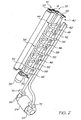
- Figure 1 shows a part of a printer including a print media feed arrangement, the print media feed arrangement including an apparatus, in accordance with the invention, for separating a sheet of print media from a stack of sheets;
- Figure 2 shows a three-dimensional view of the print media feed arrangement, including the apparatus of the invention;
- Figure 3 shows a three-dimensional view, from below, of the print media feed arrangement;
- Figure 4 shows a schematic, sectional side view of an initial stage of operation of the apparatus of the print media feed arrangement; and
- Figure 5 shows a schematic, sectional side view of a further stage of operation of the apparatus of the print media feed arrangement.
- Referring to Figure 1 of the drawings, a part of a printer is illustrated and is designated generally by the
reference numeral 10. Theprinter 10 is a high speed printer which prints both sides of print media at the rate of approximately one to two sheets per second or two to four pages per second (ie both sides of the sheet). The print media is, in this case, in the form of a stack of sheets. For ease of explanation, the invention will be described with reference to the print media being a stack of A4 sheets of paper and, more particularly, sheets of paper having a predetermined degree of porosity. - The
printer 10, to effect the high speed printing, has aprinting station 12 comprising a pair ofopposed printheads 14. Eachprinthead 14 is in the form of a microelectromechanical systems (MEMS) chip having an array of ink jet nozzles to achieve the high speed, photographic quality printing desired. The nozzles are arranged in a close packed array to provide a resolution of up to 1600 dots per inch (dpi) to facilitate the photographic quality printing. - The
printing station 12 includes a set ofprimary rollers 16 having adrive roller 18 and a drivenroller 20. The set ofprimary rollers 16 is arranged upstream of theprintheads 14 of theprinting station 12 to convey a sheet of paper to theprintheads 14. - The print media is, as described above, arranged in a
stack 30. Thestack 30 is received in a bin (not shown) of theprinter 10 and is retained against a metal bulkhead of theprinter 10 in a suitable cabinet (also not shown). - The
printer 10 includes anapparatus 32, in accordance with the invention, forming part of a paper feed arrangement for feeding a sheet of paper from thestack 30 to therollers primary rollers 16 so that the sheet of paper can be transported to theprinting station 12 for printing. The paper feed arrangement comprises a pivot rod oraxle 34 which is rotatably driven by astepper motor 36. Aswing arm 38 is arranged at each end of theaxle 34. - The
apparatus 32 includes apicker assembly 40. Thepicker assembly 40 comprises an elongate element or pick upbar 42. The pick upbar 42 is rotatably supported between theswing arms 38 proximate free ends of theswing arms 38. Accordingly, as theswing arms 34 pivot about a rotational axis of theaxle 34, the pick upbar 42 is caused to be rotated about the rotational axis of theaxle 34. - The
apparatus 32 includes a separating means 44 carried on the pick upbar 42. The separating means 44 separates a topmost sheet 30.1 of paper from thestack 30. The separating means 44 includes a fluid delivery means in the form of a plurality offluid supply conduits 46 arranged at spaced intervals along the length of thebar 42. Eachconduit 46 is in the form of a flexible hose. - As shown more clearly in Figure 3 of the drawings, the pick up
bar 42 has a plurality of alternatingfluid ports fluid conduit 46 opens out into one of thefluid ports 48 of thebar 42. An opposed, inlet end of eachconduit 46 is connected to afluid supply manifold 52. - The
apparatus 32 further includes a capturing means 54, carried by the pick upbar 42, for capturing at least a part of the topmost sheet 30.1, after the sheet 30.1 has been separated from thestack 30, for facilitating conveyance of the topmost sheet 30.1 by the pick upbar 42 to theprinting station 12, as will be described in greater detail below. - The capturing means 54 comprises a plurality of
fluid suction conduits 56 which are arranged in alternating relationship with thefluid supply conduits 46 of the separating means 44. Thefluid suction conduits 56, which are also in the form of flexible hoses, each have an inlet end in communication with one of thefluid ports 50 of the pick upbar 42. An outlet end of eachconduit 56 feeds into afluid extraction manifold 58. - The
picker assembly 40 further includes a plurality of displacement assistance means orpads 60 surrounding eachfluid port pad 60 has a stalk portion 62 (Figure 4) which projects into thebar 42 and is connected to an outlet end of one of thefluid supply conduits 46 or the inlet end of one of thefluid suction conduits 56, as the case may be. Instead, each displacement assistance means may be an elastomeric cup. Each cup is mounted via an urging means, in the form of a spring, on the pick upbar 42 to cater for a surface of thestack 30 having ripples or the like. - The
apparatus 32 includes a drive means in the form of a drive motor 64 (Figure 1). Anair pump 66 is arranged on an output shaft at one end of themotor 64 and anextraction pump 68 is arranged on an output shaft at an opposed end of themotor 64. Theair pump 66 communicates with thefluid supply manifold 52 via a solenoid operatedvalve 70 arranged at an inlet end of the manifold 52. Theextraction pump 68 communicates with an outlet end of theextraction manifold 58 via a further solenoid operatedvalve 72. - As described above, the
printer 10 is a high-speed printer which has a capacity to print at the rate of one sheet per second. To make use of this capability, it is important that the sheets of paper are fed individually to theprinting station 12 from thestack 30 in an accurate, controlled manner. Consequently, it is necessary for theapparatus 32 to separate a sheet to be transported to theprinting station 12 from thestack 30 accurately. - Further, the invention is intended particularly for use with print media which is porous such as, for example, 80 gsm paper.
- In use, to separate the topmost sheet 30.1 from the
stack 30, the pick upbar 42 is brought into close proximity to a top surface of the sheet but is held such that thepads 60 are spaced from the top surface of the topmost sheet 30.1 by a small amount, for example, 0.1 to 0.2mm. Thevalve 70 is opened and thevalve 72 is closed. Thedrive motor 64 is operated to cause air to be blown through thefluid supply manifold 52 into each of thefluid supply conduits 46. Air exhausts through theports 48 and is blown on to the top surface of the topmost sheet 30.1. Due to the porosity of the paper, the air is also driven through the topmost sheet 30.1 and impinges on a sheet of the stack which is second from the top. This results in an initial separation of the topmost sheet 30.1 from the remainder of the sheets of thestack 30. - Also, as a result of localised low pressure occurring between a lower surface of each
pad 60 and the topmost sheet 30.1 of thestack 30, the topmost sheet 30.1 is attracted at least to thosepads 60 of thepicker assembly 40 associated with thefluid supply conduits 46. Due to the passage of air through the topmost sheet 30.1, separation of the topmost sheet 30.1 from the remainder of the sheets of thestack 30 is aided. - When the topmost sheet 30.1 lifts from the sheet immediately below it in the
stack 30, a leading edge of the topmost sheet 30.1 rises. When this occurs, thevalve 70 closes and thevalve 72 opens. Opening of thevalve 72 causes air to be drawn in through theports 50 of the pick upbar 42, through thefluid suction conduits 56 and out through thefluid extraction manifold 58. As a result of this, the leading edge of the topmost sheet 30.1 is sucked against at least thosepads 60 associated with thefluid suction conduits 56 as shown in Figure 5 of the drawings and is held captive against thosepads 60. While this is occurring, the pick upbar 42 has been rotating about theaxles 34 in the direction ofarrow 74. Thepicker assembly 40 continues to rotate in the direction ofarrow 74 until a leading edge of the topmost sheet 30.1 is fed between therollers rollers 16. Thevalve 72 is closed to release the suction on the topmost sheet 30.1 enabling therollers rollers 16 to feed the sheet 30.1 to theprintheads 14 of theprinting station 12. As soon as a trailing edge of the sheet 30.1 clears thepads 60 of theassembly 40, thepicker assembly 40 returns to its position shown in Figure 4 of the drawings in readiness to feed the following sheet to theprinting station 12. - It will be appreciated that air flow parallel to a surface of the topmost sheet 30.1 of the
stack 30 results in a low friction cushion which facilitates translational motion of the sheet 30.1 relative to the pick upbar 42. This allows the sheet 30.1 to be moved by any suitable method in a direction normal to a face of the pick upbar 42 without hindering the picking action of the pick upbar 42. It also facilitates maintaining a trailing portion of the sheet 30.1 in spaced relationship relative to thestack 30 while the sheet 30.1 is being fed to the set ofrollers 16. - The applicant has found that the velocity of air through the
fluid supply conduits 46 in the initial, "blowing" direction is not critical, nor is the spacing between the pick upbar 42 and the topmost sheet 30.1 of thestack 30. Further, the weight or grade of the paper of the stack is also not critical provided that the paper in the stack has a degree of porosity. Typically, a pressure of approximately 5 kPa is present in thefluid supply conduits 46 when the air is blown on to thepaper stack 30. The air is delivered at approximately 11/s and exits the gap between thepads 60 and the topmost sheet 30.1 at a pressure of approximately 1 kPa and at a velocity of approximately 50 m/s. Theapparatus 32 has been found to operate with paper of a grade from 40 gsm to high resolution, photo-quality ink jet paper. - The applicant has found that, surprisingly, by blowing air on to the paper of the
stack 30 separation of the sheets is facilitated. This is an entirely counter-intuitive approach as one would expect that a suction-type mechanism would operate better. However, provided that the paper of thestack 30 has a degree of porosity, very good separation of the topmost sheet of paper from thestack 30 can be effected. - It will be appreciated by persons skilled in the art that numerous variations and/or modifications may be made to the invention as shown in the specific embodiments without departing from the scope of the appended claims. The present embodiments are, therefore, to be considered in all respects as illustrative and not restrictive.
Claims (15)
- An apparatus (32)for separating a sheet of print media from a stack (30) of sheets, the sheets of the stack being porous and the apparatus including:a sheet conveying means (40) for conveying a topmost sheet (30.1) of print media which has been separated from the stack (30) to a printing station (12) of a printer; anda capturing means (54), carried by the sheet conveying means (40), for capturing at least a part of said topmost sheet (30.1) and for facilitating conveyance of said topmost sheet by the sheet conveying means (40) to the printing station (12), characterized bya separating means (44), associated with the sheet conveying means (40), for separating the sheet of print media from the stack (30), the separating means including a fluid delivery means (46, 48) for blowing fluid on to a top surface of the stack (30),wherein the fluid delivery means (46,48) is configured to blow the fluid such that it is driven through a topmost sheet (30.1) and impinges on a sheet of the stack which is second from the top, thereby effecting separation of the topmost sheet (30.1) of print media from the stack.
- The apparatus of claim 1 in which the sheet conveying means comprises a picker assembly (40) for picking the topmost sheet from the stack.
- The apparatus of claim 2 in which the picker assembly (40) comprises an elongate element (42) and a plurality of displacement assistance means (60) for assisting in displacement of the topmost sheet from the stack, the displacement assistance means (60) being arranged at spaced intervals along a length of the elongate element.
- The apparatus of claim 3 in which the elongate element (42) defines a plurality of fluid ports (46) and each displacement assistance means (60) comprises a footprint-defining portion surrounding one of the ports (48) and depending from the elongate element (42).
- The apparatus of claim 4 in which the fluid delivery means comprises a plurality of fluid supply conduits (46), each conduit being in fluid communication with one of the fluid ports (48) of the elongate element (42), only certain of the fluid ports having fluid supply conduits associated with them with a remainder of the fluid ports not being in fluid communication with the fluid supply conduits.
- The apparatus of claim 5 in which the fluid supply conduits (46) are connected to, and communicate with, a fluid supply manifold (52).
- The apparatus of claim 6 in which the capturing means (54) is a fluid suction arrangement, the capturing means comprising a plurality of fluid suction conduits (56), each fluid suction conduit being in fluid communication with one of the remainder of the fluid ports (50) of the elongate element (42).
- The apparatus of claim 7 in which the fluid suction conduits (56) are connected to, and communicate with, a fluid extraction manifold (58).
- The apparatus of claim 7 in which the fluid ports (50) associated with the fluid supply conduits (46) alternate with the fluid ports (48) associated with the fluid suction conduits (56) along the length of the elongate element (42).
- The apparatus of claim 8 which comprises a fluid supply means (66) for supplying fluid to the fluid supply manifold (52) for supply to the fluid supply conduits (46) and a fluid extraction means (68) for extracting fluid from the fluid extraction manifold (58) to create a suction effect in the fluid suction conduits (56).
- The apparatus of claim 10 which comprises n drive means (64) for driving the fluid supply means (66) and the fluid extraction means (68).
- The apparatus of claim 8 which comprises a control means for controlling supply of fluid to the fluid supply manifold (52) and extraction of fluid from the fluid extraction manifold (58).
- The apparatus of claim 12 in which the control means comprises a valve (70,72) arranged in each of the fluid supply manifold (52) and the fluid extraction manifold (58).
- The apparatus of claim 13 in which each valve is electromagnetically operated.
- The apparatus of claim 1, wherein the fluid delivery means (46.48) blows fluid in a direction which is perpendicular with respect to the top surface of the stack (30).
Applications Claiming Priority (3)
| Application Number | Priority Date | Filing Date | Title |
|---|---|---|---|
| AUPR3153A AUPR315301A0 (en) | 2001-02-19 | 2001-02-19 | An Apparatus (ART102) |
| AUPR315301 | 2001-02-19 | ||
| PCT/AU2002/000069 WO2002066349A1 (en) | 2001-02-19 | 2002-01-22 | Apparatus for separating a sheet of print media from a stack of sheets |
Publications (3)
| Publication Number | Publication Date |
|---|---|
| EP1368263A1 EP1368263A1 (en) | 2003-12-10 |
| EP1368263A4 EP1368263A4 (en) | 2004-07-14 |
| EP1368263B1 true EP1368263B1 (en) | 2006-08-30 |
Family
ID=3827172
Family Applications (1)
| Application Number | Title | Priority Date | Filing Date |
|---|---|---|---|
| EP02709890A Expired - Lifetime EP1368263B1 (en) | 2001-02-19 | 2002-01-22 | Apparatus for separating a sheet of print media from a stack of sheets |
Country Status (10)
| Country | Link |
|---|---|
| US (17) | US7328896B2 (en) |
| EP (1) | EP1368263B1 (en) |
| JP (1) | JP4180378B2 (en) |
| CN (1) | CN1225391C (en) |
| AT (1) | ATE337993T1 (en) |
| AU (1) | AUPR315301A0 (en) |
| DE (1) | DE60214346D1 (en) |
| IL (2) | IL157308A0 (en) |
| WO (1) | WO2002066349A1 (en) |
| ZA (1) | ZA200306302B (en) |
Families Citing this family (18)
| Publication number | Priority date | Publication date | Assignee | Title |
|---|---|---|---|---|
| AUPR292501A0 (en) * | 2001-02-07 | 2001-03-01 | Silverbrook Research Pty. Ltd. | A method and apparatus (ART100) |
| AUPR315301A0 (en) * | 2001-02-19 | 2001-03-15 | Silverbrook Research Pty. Ltd. | An Apparatus (ART102) |
| DE10331189A1 (en) * | 2002-08-02 | 2004-02-26 | Heidelberger Druckmaschinen Ag | Suction air producing device for printing press, has movable air delivery unit accommodated on sheet holding device, and actuating unit fixed to machine frame, which is movable relative to sheet holding device |
| US7161511B2 (en) * | 2005-06-03 | 2007-01-09 | General Electric Company | Linearization system and method |
| US7700083B2 (en) * | 2005-10-24 | 2010-04-20 | Kevin Meehan | Skin care composition for accelerated production of collagen proteins and method of fabricating same |
| US20070138733A1 (en) * | 2005-12-16 | 2007-06-21 | Chris Gray | Pick mechanism |
| JP4597064B2 (en) * | 2006-02-14 | 2010-12-15 | シャープ株式会社 | Paper feeder |
| JP2008056363A (en) * | 2006-08-29 | 2008-03-13 | Nec Corp | Paper sheet separation mechanism, paper sheet separation method, and paper sheet feeder |
| JP6087492B2 (en) * | 2008-01-10 | 2017-03-01 | ジェネリクス・[ユーケー]・リミテッド | A new process for preparing scopine esters |
| US7976013B1 (en) * | 2008-02-22 | 2011-07-12 | Young Ronald J | Cyclically controlled paper feeder with optical stack level control |
| AU2010280497B2 (en) | 2009-08-07 | 2015-10-22 | Generics [Uk] Limited | Anhydrate of tiotropium bromide |
| US8671990B2 (en) | 2010-02-12 | 2014-03-18 | Moog Inc. | Vacuum valve apparatus and method |
| KR101063555B1 (en) | 2011-07-05 | 2011-09-07 | 이재영 | Air picker easy to install and replace |
| CN112368152B (en) | 2018-03-12 | 2023-06-30 | 惠普发展公司,有限责任合伙企业 | Purge manifold |
| DE102018121542B4 (en) * | 2018-09-04 | 2022-03-17 | Koenig & Bauer Ag | Device for printing hollow bodies |
| KR102048155B1 (en) * | 2018-09-05 | 2019-11-22 | 삼성전기주식회사 | Multilayer ceramic electronic component |
| WO2021126241A1 (en) * | 2019-12-20 | 2021-06-24 | Hewlett-Packard Development Company, L.P. | Print apparatus and methods |
| CN111559657B (en) * | 2020-05-15 | 2022-08-02 | 深圳汉华工业数码设备有限公司 | Material loading conveying equipment |
Family Cites Families (105)
| Publication number | Priority date | Publication date | Assignee | Title |
|---|---|---|---|---|
| US508876A (en) * | 1893-11-14 | Thaddieus s | ||
| DE824953C (en) * | 1949-05-13 | 1951-12-17 | Rotaprint A G | Printing machine with sheet feeder |
| DE1060874B (en) * | 1955-02-26 | 1959-07-09 | Falz Und Heftmaschinenwerk Lei | Method for separating the sheets of a stack by means of suction air |
| US3070212A (en) * | 1960-10-10 | 1962-12-25 | Cons Thermoplastics Company | Stacking machine |
| US3130602A (en) * | 1962-07-30 | 1964-04-28 | Container Corp | Disconnect mechanism for reciprocating drive |
| GB1040432A (en) * | 1963-04-06 | 1966-08-24 | Caledex Machine Company Ltd | Improvements in and relating to box wrapping apparatus |
| US3502815A (en) * | 1967-03-17 | 1970-03-24 | Xerox Corp | Tone signalling bandwidth compression system |
| GB1200037A (en) * | 1967-08-21 | 1970-07-29 | Adamovske Strojirny Np | Improvements in or relating to drives for pneumatic feed devices |
| US3938800A (en) * | 1972-04-26 | 1976-02-17 | Heidelberger Druckmaschinen Aktiengesellschaft | Suction head for sheet feeding apparatus |
| US3836139A (en) * | 1972-08-28 | 1974-09-17 | Hamada Printing Press | Paper feeding apparatus for use in printing machine |
| DE2429421C2 (en) * | 1974-06-19 | 1981-12-10 | Vits-Maschinenbau Gmbh, 4018 Langenfeld | Device for lifting the top sheet of a stack with blown air |
| US3991997A (en) * | 1974-12-30 | 1976-11-16 | Barber Walter W | Paper feed mechanism for offset printer |
| US4089518A (en) * | 1976-02-24 | 1978-05-16 | Veb Polygraph Leipzig Kombinat Fur Polygraphische Maschinen Und Ausrustungen | Sheet-handling apparatus |
| US4146217A (en) * | 1977-06-02 | 1979-03-27 | Barker Roger J | Sheet feed mechanism for offset printing machines and the like |
| DE2725547C2 (en) * | 1977-06-07 | 1983-12-22 | De La Rue Giori S.A., 1003 Lausanne | Method and device for the fan-like pushing of bow-shaped or booklet-shaped objects |
| US4258513A (en) * | 1979-08-08 | 1981-03-31 | Helmut Bergman | Space enclosing structure |
| US4458891A (en) * | 1981-03-04 | 1984-07-10 | Komori Printing Machinery Co., Ltd. | Paper feeder |
| US4384710A (en) * | 1981-05-21 | 1983-05-24 | Alloyd Co., Inc. | Sheet feeder and transfer apparatus |
| US4585222A (en) * | 1982-03-01 | 1986-04-29 | Sharp Kabushiki Kaisha | Sheet paper attracting system |
| DE3211610C2 (en) * | 1982-03-30 | 1985-04-18 | Agfa-Gevaert Ag, 5090 Leverkusen | Device for removing a sheet from a stack |
| US4496143A (en) * | 1982-06-01 | 1985-01-29 | Emf Corporation | Sheet feeder |
| JPS58220030A (en) * | 1982-06-15 | 1983-12-21 | Dainippon Screen Mfg Co Ltd | Automatic feed and exhaust device for sheets |
| US4635365A (en) * | 1983-09-09 | 1987-01-13 | Dainippon Screen Seizo Kabushiki Kaisha | Coordinate plotter with automatic punching device |
| DE8406329U1 (en) * | 1984-03-01 | 1984-05-30 | Heidelberger Druckmaschinen Ag, 6900 Heidelberg | STACKING AT THE BOW FEEDER OF PRINTING MACHINES |
| US4662622A (en) * | 1984-07-18 | 1987-05-05 | Tektronix, Inc. | Air density adaptive vacuum controller |
| DE3447331A1 (en) * | 1984-12-24 | 1986-06-26 | Mathias Bäuerle GmbH, 7742 ST. Georgen | PNEUMATIC BOW FEEDER |
| US4669716A (en) * | 1985-07-29 | 1987-06-02 | Bell & Howell | Method and device for deflecting a sheet prior to feeding |
| US4848764A (en) * | 1986-05-23 | 1989-07-18 | Fuji Photo Film Co., Ltd. | Sheet feeding mechanism |
| DE3705741A1 (en) * | 1987-02-23 | 1988-09-01 | Hilti Ag | DISPENSING DEVICE FOR FLOWABLE MEASURES |
| DE3706058A1 (en) * | 1987-02-25 | 1988-09-08 | Heidelberger Druckmasch Ag | FEEDER FOR A PRINTING MACHINE |
| US4887805A (en) * | 1988-03-10 | 1989-12-19 | Xerox Corporation | Top vacuum corrugation feeder |
| US4968019A (en) * | 1988-07-12 | 1990-11-06 | Brother Kogyo Kabushiki Kaisha | Sheet feed mechanism and method of feeding sheet |
| DE3834400A1 (en) * | 1988-10-10 | 1990-04-19 | Heidelberger Druckmasch Ag | LAXING BLOWERS FOR BOW FEEDERS OF BOW ROTARY PRINTING MACHINES |
| US5041879A (en) * | 1989-01-30 | 1991-08-20 | Brother Kogyo Kabushiki Kaisha | Sheet supplying device having control unit for sheet supplying operation |
| SU1680606A1 (en) * | 1989-02-03 | 1991-09-30 | Московский Полиграфический Институт | Method of successive feed of flexible sheet stock from pile |
| JP2786664B2 (en) * | 1989-04-07 | 1998-08-13 | 株式会社リコー | Refeeder |
| EP0411533B1 (en) * | 1989-07-31 | 1995-11-15 | Sharp Kabushiki Kaisha | Recirculating sheet feeding apparatus |
| DE3931995A1 (en) * | 1989-09-26 | 1991-04-04 | Heidelberger Druckmasch Ag | DEVICE FOR AIR CONTROLLING FEEDER BLOW AND SUCTION SUCTION AIR IN BOW FEEDERS OF PRINTING MACHINES |
| DE3938556C2 (en) * | 1989-11-21 | 1996-09-05 | Heidelberger Druckmasch Ag | Suction head for the feeder of a sheet-fed rotary printing machine |
| US5542658A (en) * | 1989-11-21 | 1996-08-06 | Heidelberger Druckmaschinen Ag | Suction head for a feeder of a sheet-fed rotary printing press |
| JP2802807B2 (en) * | 1990-03-26 | 1998-09-24 | キヤノン株式会社 | Film remaining detection mechanism |
| US5098077A (en) * | 1990-11-23 | 1992-03-24 | Eastman Kodak Company | Recirculating document feeder with stack weight determined pressurized air/vacuum levels and method |
| US5184813A (en) * | 1991-03-13 | 1993-02-09 | Koenig & Bauer Aktiengesellschaft | Separating jet blast air control assembly |
| DE4116491C1 (en) * | 1991-05-21 | 1992-06-17 | Heidelberger Druckmaschinen Ag, 6900 Heidelberg, De | |
| JPH0733191B2 (en) | 1991-08-23 | 1995-04-12 | リョービ株式会社 | Printer feeding device |
| US5125637A (en) * | 1991-08-27 | 1992-06-30 | Kansa Corporation | Feeding mechanism for newspaper compiler having a movable vacuum valve assembly |
| EP0553455B1 (en) * | 1992-01-30 | 1998-03-25 | Ferag AG | Method and device for lifting printed products from a stack |
| US5284334A (en) * | 1992-04-01 | 1994-02-08 | Minolta Camera Kabushiki Kaisha | Sheet feeding device |
| JPH05305045A (en) | 1992-04-30 | 1993-11-19 | Tokyo Electric Co Ltd | Vacuum cleaner |
| DE4218421A1 (en) * | 1992-06-04 | 1993-12-09 | Heidelberger Druckmasch Ag | Sheet guide in the delivery of a printing press |
| JP2568437Y2 (en) * | 1992-09-03 | 1998-04-15 | 株式会社小森コーポレーション | Paper suction device |
| JP2902227B2 (en) * | 1992-10-29 | 1999-06-07 | ジューキ株式会社 | Enclosure supply device of enclosing and sealing device |
| US6112191A (en) * | 1993-02-18 | 2000-08-29 | Every Penny Counts, Inc. | Method and system to create and distribute excess funds from consumer spending transactions |
| US5466919A (en) * | 1993-04-02 | 1995-11-14 | Hovakimian; Henry | Credit/charge card system enabling purchasers to contribute to selected charities |
| DE4314971A1 (en) * | 1993-05-06 | 1994-11-10 | Heidelberger Druckmasch Ag | Sheet feeder of a printing press |
| JPH07157117A (en) * | 1993-12-08 | 1995-06-20 | Fuji Photo Film Co Ltd | Board shape or box shape vacuum chuck device |
| US5716047A (en) * | 1994-03-31 | 1998-02-10 | Canon Kabushiki Kaisha | Recording or reading apparatus and sheet supply device with drive system having first and second mechanisms |
| US5836582A (en) * | 1994-04-04 | 1998-11-17 | Canon Kabushiki Kaisha | Sheet feeding device with air injectors for separating sheets |
| FR2718678B1 (en) * | 1994-04-15 | 1996-05-24 | Gemplus Card Int | Simultaneous two-sided printing machine. |
| US5542685A (en) * | 1994-05-06 | 1996-08-06 | Komag, Inc. | Memory disk clamp and method |
| DE19516132C2 (en) * | 1995-05-03 | 1997-04-17 | Roland Man Druckmasch | Sample sheet collection |
| JP3207711B2 (en) * | 1995-05-08 | 2001-09-10 | シャープ株式会社 | Air feeding device |
| DE29510214U1 (en) * | 1995-06-23 | 1995-08-31 | Heidelberger Druckmasch Ag | Device for the cyclical lifting and lowering of a lifting suction device in the feeder of a sheet processing machine with means for adjusting the suction height |
| DE19522901C1 (en) * | 1995-06-23 | 1996-10-02 | Heidelberger Druckmasch Ag | Device for cyclic lifting and lowering of lift sucker on feeder of paper processing machine |
| JP3324920B2 (en) * | 1995-11-21 | 2002-09-17 | シャープ株式会社 | Paper feeder |
| JP3673604B2 (en) * | 1996-10-31 | 2005-07-20 | キヤノン株式会社 | Sheet supply apparatus and recording / reading apparatus using the apparatus |
| JPH10236677A (en) * | 1997-02-28 | 1998-09-08 | Canon Inc | Sheet supply device and recording/reading device using it |
| US20010047342A1 (en) * | 1997-06-16 | 2001-11-29 | Vincent Cuervo | Credit or debit cards of all kinds to be issued with a bank savings account attched |
| US6139005A (en) * | 1997-09-29 | 2000-10-31 | Eastman Kodak Company | Film supply system for use with a photosensitive film imager |
| US5816156A (en) * | 1997-10-07 | 1998-10-06 | Minkle; Richard | Suction foot reapportioning system and printing press |
| US6070153A (en) * | 1997-11-21 | 2000-05-30 | Simpson; Mark S. | System and method for automatically investing a portion of a credit card interest charged amount in an investment account |
| DE19856243A1 (en) * | 1997-12-20 | 1999-06-24 | Heidelberger Druckmasch Ag | Air supply for linear lifters or conveyors in sheet processing machine |
| US6145830A (en) * | 1998-01-15 | 2000-11-14 | Fuji Photo Film Co., Ltd. | Sheet material supplying apparatus |
| US6386585B1 (en) * | 1998-04-22 | 2002-05-14 | Hartwig Muller | Roll bar |
| JP2000062979A (en) | 1998-08-25 | 2000-02-29 | Hiroshi Akashi | Sheet transferring device |
| US6345818B1 (en) * | 1998-10-26 | 2002-02-12 | Fanuc Robotics North America Inc. | Robotic manipulator having a gripping tool assembly |
| DE19947573A1 (en) * | 1999-10-01 | 2001-04-05 | Heidelberger Druckmasch Ag | Lift-drag suction gear for sheet processing machine |
| DE10057963A1 (en) * | 1999-12-17 | 2001-06-21 | Heidelberger Druckmasch Ag | Sheet separation method from sheet pile for rotary printing machine, involves lifting of sheet by lifting device above transfer level and has suction device to transport sheet |
| US6543759B2 (en) * | 2000-02-23 | 2003-04-08 | Kyocera Mita Corporation | Paper feeder for use in image forming apparatus |
| FR2805631B1 (en) * | 2000-02-28 | 2003-09-12 | France Telecom | PAYMENT TO GOOD WORKS BY PREPAID CARD |
| US6264188B1 (en) * | 2000-06-12 | 2001-07-24 | Xerox Corporation | Sheet feeding apparatus having an adaptive air fluffer |
| US6398208B1 (en) * | 2000-06-12 | 2002-06-04 | Xerox Corporation | Sheet feeding apparatus having an air plenum with a leaky seal |
| US6352255B1 (en) * | 2000-06-12 | 2002-03-05 | Xerox Corporation | Reversing shuttle feeder |
| US6398207B1 (en) * | 2000-06-12 | 2002-06-04 | Xerox Corporation | Sheet feeding apparatus having an air plenum with a seal |
| US6398206B1 (en) * | 2000-06-12 | 2002-06-04 | Xerox Corporation | Sheet feeding apparatus having an air plenum with a corrugated surface |
| US7502758B2 (en) * | 2001-09-12 | 2009-03-10 | Every Penny Counts, Inc. | Creation and distribution of excess funds, deposits, and payments |
| US6386535B1 (en) * | 2000-09-15 | 2002-05-14 | Silverbrook Research Pty Ltd | Loading mechanism for a modular commercial printer |
| US20020077904A1 (en) * | 2000-12-14 | 2002-06-20 | Naushad Ali | Loyalty program |
| US6634635B2 (en) * | 2001-01-31 | 2003-10-21 | Heidelberger Druckmaschinen Ag | Lift hook for a sheet separating device |
| AUPR292501A0 (en) * | 2001-02-07 | 2001-03-01 | Silverbrook Research Pty. Ltd. | A method and apparatus (ART100) |
| US20020111904A1 (en) * | 2001-02-13 | 2002-08-15 | Gruber Harry E. | Method and system for soliciting charitable donation during electronic commerce |
| AUPR315301A0 (en) * | 2001-02-19 | 2001-03-15 | Silverbrook Research Pty. Ltd. | An Apparatus (ART102) |
| US20020174063A1 (en) * | 2001-05-17 | 2002-11-21 | Castagna Realty Co., Inc. | Automated donation process and system therefor |
| US7809641B2 (en) * | 2001-07-26 | 2010-10-05 | Jpmorgan Chase Bank, National Association | System and method for funding a collective account |
| GB0127298D0 (en) * | 2001-11-14 | 2002-01-02 | Ncr Int Inc | Transaction system |
| JP3845005B2 (en) * | 2001-12-12 | 2006-11-15 | 富士写真フイルム株式会社 | Image recording material single wafer equipment |
| US20030225649A1 (en) * | 2002-05-31 | 2003-12-04 | Simpson Mark S. | System and method for automatically investing in an investment or savings account by using the "rounded up" of credit card purchase amounts to produce savings/investment amounts |
| US20060122856A1 (en) * | 2002-06-06 | 2006-06-08 | Benevolink Corporation | System and method for enabling consumers to add personal charitable contributions and transfer the right to designate a beneficiary to other consumers |
| US6669187B1 (en) * | 2002-06-13 | 2003-12-30 | Xerox Corporation | Rear jet air knife |
| US20040117249A1 (en) * | 2002-12-16 | 2004-06-17 | Wang Annie X. | Business improvement program with on-line access |
| US20040249752A1 (en) * | 2003-06-06 | 2004-12-09 | Impact Consulting & Management | Charity funding method using an open-ended stored-value card |
| US20060089874A1 (en) * | 2004-10-22 | 2006-04-27 | Newman Christian D | Generating income for a beneficiary organisation and loyalty points using purchases by a consumer |
| US20060242041A1 (en) * | 2005-04-20 | 2006-10-26 | Canney Michael L | Method and financing system for funding a personal account |
| US20070033134A1 (en) * | 2005-08-02 | 2007-02-08 | Bank Of America Corporation | Automatic Savings Program |
| US20070080213A1 (en) * | 2005-10-12 | 2007-04-12 | Workman Lloyd T | Aggregate electronic change saving method |
-
2001
- 2001-02-19 AU AUPR3153A patent/AUPR315301A0/en not_active Abandoned
-
2002
- 2002-01-22 WO PCT/AU2002/000069 patent/WO2002066349A1/en active IP Right Grant
- 2002-01-22 CN CNB028051297A patent/CN1225391C/en not_active Expired - Fee Related
- 2002-01-22 IL IL15730802A patent/IL157308A0/en active IP Right Grant
- 2002-01-22 DE DE60214346T patent/DE60214346D1/en not_active Expired - Lifetime
- 2002-01-22 EP EP02709890A patent/EP1368263B1/en not_active Expired - Lifetime
- 2002-01-22 AT AT02709890T patent/ATE337993T1/en not_active IP Right Cessation
- 2002-01-22 JP JP2002565873A patent/JP4180378B2/en not_active Expired - Fee Related
- 2002-01-22 US US10/470,942 patent/US7328896B2/en not_active Expired - Fee Related
- 2002-01-23 US US10/052,424 patent/US6568670B2/en not_active Expired - Fee Related
- 2002-12-04 US US10/309,226 patent/US6648321B2/en not_active Expired - Fee Related
-
2003
- 2003-08-07 IL IL157308A patent/IL157308A/en not_active IP Right Cessation
- 2003-08-14 ZA ZA200306302A patent/ZA200306302B/en unknown
- 2003-10-28 US US10/693,876 patent/US6834851B2/en not_active Expired - Fee Related
- 2003-10-28 US US10/693,873 patent/US6896252B2/en not_active Expired - Fee Related
- 2003-10-28 US US10/693,875 patent/US6820871B2/en not_active Expired - Fee Related
-
2004
- 2004-10-28 US US10/974,754 patent/US7172191B2/en not_active Expired - Fee Related
- 2004-11-12 US US10/986,328 patent/US20070145669A9/en not_active Abandoned
- 2004-11-12 US US10/986,329 patent/US7222845B2/en not_active Expired - Fee Related
-
2007
- 2007-05-03 US US11/744,183 patent/US7556257B2/en not_active Expired - Fee Related
-
2008
- 2008-01-08 US US11/970,993 patent/US7597314B2/en not_active Expired - Fee Related
- 2008-06-24 US US12/145,490 patent/US7540486B2/en not_active Expired - Fee Related
- 2008-06-24 US US12/145,495 patent/US7540487B2/en not_active Expired - Fee Related
- 2008-06-24 US US12/145,497 patent/US7540488B2/en not_active Expired - Fee Related
- 2008-06-24 US US12/145,493 patent/US7549628B2/en not_active Expired - Fee Related
- 2008-06-24 US US12/145,486 patent/US7770883B2/en not_active Expired - Fee Related
- 2008-11-18 US US12/273,461 patent/US20090115121A1/en not_active Abandoned
Also Published As
Similar Documents
| Publication | Publication Date | Title |
|---|---|---|
| US7597314B2 (en) | Air-based picker assembly for a printer | |
| US6848686B2 (en) | Printing assembly for printing on sheets of media from a stack | |
| AU2002227775B2 (en) | Apparatus for separating a sheet of print media from a stack of sheets | |
| AU2004210571B2 (en) | A printer incorporating an apparatus for separating a sheet of print media from a stack of sheets | |
| AU2002227775A1 (en) | Apparatus for separating a sheet of print media from a stack of sheets |
Legal Events
| Date | Code | Title | Description |
|---|---|---|---|
| PUAI | Public reference made under article 153(3) epc to a published international application that has entered the european phase |
Free format text: ORIGINAL CODE: 0009012 |
|
| 17P | Request for examination filed |
Effective date: 20030905 |
|
| AK | Designated contracting states |
Kind code of ref document: A1 Designated state(s): AT BE CH CY DE DK ES FI FR GB GR IE IT LI LU MC NL PT SE TR |
|
| AX | Request for extension of the european patent |
Extension state: AL LT LV MK RO SI |
|
| A4 | Supplementary search report drawn up and despatched |
Effective date: 20040527 |
|
| RIC1 | Information provided on ipc code assigned before grant |
Ipc: 7B 65H 3/08 B Ipc: 7B 65H 5/06 B Ipc: 7B 65H 3/48 B Ipc: 7B 65H 3/14 A |
|
| GRAP | Despatch of communication of intention to grant a patent |
Free format text: ORIGINAL CODE: EPIDOSNIGR1 |
|
| GRAS | Grant fee paid |
Free format text: ORIGINAL CODE: EPIDOSNIGR3 |
|
| GRAA | (expected) grant |
Free format text: ORIGINAL CODE: 0009210 |
|
| AK | Designated contracting states |
Kind code of ref document: B1 Designated state(s): AT BE CH CY DE DK ES FI FR GB GR IE IT LI LU MC NL PT SE TR |
|
| PG25 | Lapsed in a contracting state [announced via postgrant information from national office to epo] |
Ref country code: IT Free format text: LAPSE BECAUSE OF FAILURE TO SUBMIT A TRANSLATION OF THE DESCRIPTION OR TO PAY THE FEE WITHIN THE PRESCRIBED TIME-LIMIT;WARNING: LAPSES OF ITALIAN PATENTS WITH EFFECTIVE DATE BEFORE 2007 MAY HAVE OCCURRED AT ANY TIME BEFORE 2007. THE CORRECT EFFECTIVE DATE MAY BE DIFFERENT FROM THE ONE RECORDED. Effective date: 20060830 Ref country code: NL Free format text: LAPSE BECAUSE OF FAILURE TO SUBMIT A TRANSLATION OF THE DESCRIPTION OR TO PAY THE FEE WITHIN THE PRESCRIBED TIME-LIMIT Effective date: 20060830 Ref country code: BE Free format text: LAPSE BECAUSE OF FAILURE TO SUBMIT A TRANSLATION OF THE DESCRIPTION OR TO PAY THE FEE WITHIN THE PRESCRIBED TIME-LIMIT Effective date: 20060830 Ref country code: FI Free format text: LAPSE BECAUSE OF FAILURE TO SUBMIT A TRANSLATION OF THE DESCRIPTION OR TO PAY THE FEE WITHIN THE PRESCRIBED TIME-LIMIT Effective date: 20060830 Ref country code: LI Free format text: LAPSE BECAUSE OF FAILURE TO SUBMIT A TRANSLATION OF THE DESCRIPTION OR TO PAY THE FEE WITHIN THE PRESCRIBED TIME-LIMIT Effective date: 20060830 Ref country code: CH Free format text: LAPSE BECAUSE OF FAILURE TO SUBMIT A TRANSLATION OF THE DESCRIPTION OR TO PAY THE FEE WITHIN THE PRESCRIBED TIME-LIMIT Effective date: 20060830 Ref country code: AT Free format text: LAPSE BECAUSE OF FAILURE TO SUBMIT A TRANSLATION OF THE DESCRIPTION OR TO PAY THE FEE WITHIN THE PRESCRIBED TIME-LIMIT Effective date: 20060830 |
|
| REG | Reference to a national code |
Ref country code: GB Ref legal event code: FG4D |
|
| REG | Reference to a national code |
Ref country code: CH Ref legal event code: EP |
|
| REG | Reference to a national code |
Ref country code: IE Ref legal event code: FG4D |
|
| REF | Corresponds to: |
Ref document number: 60214346 Country of ref document: DE Date of ref document: 20061012 Kind code of ref document: P |
|
| PG25 | Lapsed in a contracting state [announced via postgrant information from national office to epo] |
Ref country code: SE Free format text: LAPSE BECAUSE OF FAILURE TO SUBMIT A TRANSLATION OF THE DESCRIPTION OR TO PAY THE FEE WITHIN THE PRESCRIBED TIME-LIMIT Effective date: 20061130 Ref country code: DK Free format text: LAPSE BECAUSE OF FAILURE TO SUBMIT A TRANSLATION OF THE DESCRIPTION OR TO PAY THE FEE WITHIN THE PRESCRIBED TIME-LIMIT Effective date: 20061130 |
|
| PG25 | Lapsed in a contracting state [announced via postgrant information from national office to epo] |
Ref country code: DE Free format text: LAPSE BECAUSE OF FAILURE TO SUBMIT A TRANSLATION OF THE DESCRIPTION OR TO PAY THE FEE WITHIN THE PRESCRIBED TIME-LIMIT Effective date: 20061201 |
|
| PG25 | Lapsed in a contracting state [announced via postgrant information from national office to epo] |
Ref country code: ES Free format text: LAPSE BECAUSE OF FAILURE TO SUBMIT A TRANSLATION OF THE DESCRIPTION OR TO PAY THE FEE WITHIN THE PRESCRIBED TIME-LIMIT Effective date: 20061211 |
|
| PG25 | Lapsed in a contracting state [announced via postgrant information from national office to epo] |
Ref country code: MC Free format text: LAPSE BECAUSE OF NON-PAYMENT OF DUE FEES Effective date: 20070131 |
|
| PG25 | Lapsed in a contracting state [announced via postgrant information from national office to epo] |
Ref country code: PT Free format text: LAPSE BECAUSE OF FAILURE TO SUBMIT A TRANSLATION OF THE DESCRIPTION OR TO PAY THE FEE WITHIN THE PRESCRIBED TIME-LIMIT Effective date: 20070212 |
|
| REG | Reference to a national code |
Ref country code: CH Ref legal event code: PL |
|
| NLV1 | Nl: lapsed or annulled due to failure to fulfill the requirements of art. 29p and 29m of the patents act | ||
| EN | Fr: translation not filed | ||
| PLBE | No opposition filed within time limit |
Free format text: ORIGINAL CODE: 0009261 |
|
| STAA | Information on the status of an ep patent application or granted ep patent |
Free format text: STATUS: NO OPPOSITION FILED WITHIN TIME LIMIT |
|
| 26N | No opposition filed |
Effective date: 20070531 |
|
| PG25 | Lapsed in a contracting state [announced via postgrant information from national office to epo] |
Ref country code: GR Free format text: LAPSE BECAUSE OF FAILURE TO SUBMIT A TRANSLATION OF THE DESCRIPTION OR TO PAY THE FEE WITHIN THE PRESCRIBED TIME-LIMIT Effective date: 20061201 Ref country code: FR Free format text: LAPSE BECAUSE OF FAILURE TO SUBMIT A TRANSLATION OF THE DESCRIPTION OR TO PAY THE FEE WITHIN THE PRESCRIBED TIME-LIMIT Effective date: 20070511 |
|
| PG25 | Lapsed in a contracting state [announced via postgrant information from national office to epo] |
Ref country code: FR Free format text: LAPSE BECAUSE OF FAILURE TO SUBMIT A TRANSLATION OF THE DESCRIPTION OR TO PAY THE FEE WITHIN THE PRESCRIBED TIME-LIMIT Effective date: 20060830 |
|
| PG25 | Lapsed in a contracting state [announced via postgrant information from national office to epo] |
Ref country code: LU Free format text: LAPSE BECAUSE OF NON-PAYMENT OF DUE FEES Effective date: 20070122 Ref country code: CY Free format text: LAPSE BECAUSE OF FAILURE TO SUBMIT A TRANSLATION OF THE DESCRIPTION OR TO PAY THE FEE WITHIN THE PRESCRIBED TIME-LIMIT Effective date: 20060830 |
|
| PG25 | Lapsed in a contracting state [announced via postgrant information from national office to epo] |
Ref country code: TR Free format text: LAPSE BECAUSE OF FAILURE TO SUBMIT A TRANSLATION OF THE DESCRIPTION OR TO PAY THE FEE WITHIN THE PRESCRIBED TIME-LIMIT Effective date: 20060830 |
|
| PGFP | Annual fee paid to national office [announced via postgrant information from national office to epo] |
Ref country code: GB Payment date: 20120727 Year of fee payment: 11 Ref country code: IE Payment date: 20120727 Year of fee payment: 11 |
|
| GBPC | Gb: european patent ceased through non-payment of renewal fee |
Effective date: 20130122 |
|
| REG | Reference to a national code |
Ref country code: IE Ref legal event code: MM4A |
|
| PG25 | Lapsed in a contracting state [announced via postgrant information from national office to epo] |
Ref country code: GB Free format text: LAPSE BECAUSE OF NON-PAYMENT OF DUE FEES Effective date: 20130122 |
|
| PG25 | Lapsed in a contracting state [announced via postgrant information from national office to epo] |
Ref country code: IE Free format text: LAPSE BECAUSE OF NON-PAYMENT OF DUE FEES Effective date: 20130122 |