EP1369669A1 - Method and system for autoflight information display - Google Patents
Method and system for autoflight information display Download PDFInfo
- Publication number
- EP1369669A1 EP1369669A1 EP03076620A EP03076620A EP1369669A1 EP 1369669 A1 EP1369669 A1 EP 1369669A1 EP 03076620 A EP03076620 A EP 03076620A EP 03076620 A EP03076620 A EP 03076620A EP 1369669 A1 EP1369669 A1 EP 1369669A1
- Authority
- EP
- European Patent Office
- Prior art keywords
- aircraft
- displaying
- display medium
- location
- region
- Prior art date
- Legal status (The legal status is an assumption and is not a legal conclusion. Google has not performed a legal analysis and makes no representation as to the accuracy of the status listed.)
- Withdrawn
Links
- 238000000034 method Methods 0.000 title claims abstract description 63
- 230000006870 function Effects 0.000 claims description 25
- 230000008859 change Effects 0.000 claims description 12
- RZVHIXYEVGDQDX-UHFFFAOYSA-N 9,10-anthraquinone Chemical compound C1=CC=C2C(=O)C3=CC=CC=C3C(=O)C2=C1 RZVHIXYEVGDQDX-UHFFFAOYSA-N 0.000 description 29
- 230000008569 process Effects 0.000 description 23
- 230000000007 visual effect Effects 0.000 description 9
- 230000008901 benefit Effects 0.000 description 4
- 230000009194 climbing Effects 0.000 description 3
- 238000010586 diagram Methods 0.000 description 3
- 230000009471 action Effects 0.000 description 1
- 239000002131 composite material Substances 0.000 description 1
- 230000000694 effects Effects 0.000 description 1
- 238000012986 modification Methods 0.000 description 1
- 230000004048 modification Effects 0.000 description 1
Images


Classifications
-
- G—PHYSICS
- G01—MEASURING; TESTING
- G01C—MEASURING DISTANCES, LEVELS OR BEARINGS; SURVEYING; NAVIGATION; GYROSCOPIC INSTRUMENTS; PHOTOGRAMMETRY OR VIDEOGRAMMETRY
- G01C23/00—Combined instruments indicating more than one navigational value, e.g. for aircraft; Combined measuring devices for measuring two or more variables of movement, e.g. distance, speed or acceleration
-
- G—PHYSICS
- G01—MEASURING; TESTING
- G01D—MEASURING NOT SPECIALLY ADAPTED FOR A SPECIFIC VARIABLE; ARRANGEMENTS FOR MEASURING TWO OR MORE VARIABLES NOT COVERED IN A SINGLE OTHER SUBCLASS; TARIFF METERING APPARATUS; MEASURING OR TESTING NOT OTHERWISE PROVIDED FOR
- G01D7/00—Indicating measured values
- G01D7/02—Indicating value of two or more variables simultaneously
- G01D7/04—Indicating value of two or more variables simultaneously using a separate indicating element for each variable
Definitions
- the present invention relates generally to methods and apparatuses for displaying autoflight information, such as autothrottle and/or autopilot mode information.
- the automatic flight control devices typically include an autothrottle that controls engine thrust, and an autopilot that controls both pitch attitude (via the aircraft elevators) and roll attitude (via the aircraft ailerons).
- Information regarding the status and activities of the flight control devices is typically displayed on a display device, such as a CRT, LCD or other graphical user interface.
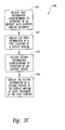
- Figure 1 illustrates a typical display device 10 that presents a display 30 in accordance with the prior art.
- the display 30 includes an air speed display 33, an altitude display 34, an attitude display 35, and a heading display 36.
- the display 30 also includes a series of annunciators, each indicating (via a textual shorthand) which of a variety of pre-defined modes a corresponding one of the automatic flight control devices is operating in.
- the display 30 can include an autothrottle mode annunciator 55, a roll mode annunciator 66, and a pitch mode annunciator 45.
- SPD indicates that the aircraft autothrottle is controlling the engine thrust based on a target aircraft speed.
- LOC indicates that the roll control portion of the autopilot is controlling to maintain a track on a localizer beam
- G/S indicates that the pitch control portion of the autopilot is controlling the elevators based on a target glide slope.
- FIG. 2 illustrates a separate display device 10a that presents an engine indication display 60 in accordance with the prior art.
- the display 60 can include graphical depictions of the exhaust pressure ratio (EPR), engine RPM (N1) and exhaust gas temperature (EGT) for each engine.
- the display 60 can also include a textual thrust limit indicator 62a, a numerical thrust limit indicator 62b, and a numerical actual thrust indicator 61.
- One drawback with the display 30 described above with reference to Figure 1 is that the mode annunciators are relatively cryptic and require the pilot to memorize the type of action performed by each flight control device in each mode.
- a drawback with the engine indication display 60 shown in Figure 2 is that it requires the pilot to look at a separate display for engine information. Accordingly, the pilot may need to move his or her eyes back and forth between multiple displays to understand various aspects of the flight control operation.
- the present invention is directed toward methods and systems for displaying information corresponding to the operation of automatic aircraft controllers.
- the method can be implemented on a computer, a computer readable medium, or a computer system.
- the method can include displaying alphanumeric information corresponding to the operation of the automatic aircraft controller at a first location of a display medium.
- the method can further include (if the automatic aircraft controller is not controlling the aircraft function based at least in part on the target aircraft speed), displaying the alphanumeric information at a second location of the display medium different than the first location.
- the method can include displaying an aircraft speed at a first region of the display medium and displaying an aircraft altitude at a second region of the display medium different than the first region.
- Displaying the alphanumeric information at the first location can include displaying at least a portion of the alphanumeric information at least proximate to the first region of the display medium, and displaying the alphanumeric information at the second location can include displaying at least a portion of the alphanumeric information at least proximate to the second region of the display medium.
- the automatic aircraft controller can include an autopilot, and in another aspect of the invention, the automatic aircraft controller can include an autothrottle.
- the automatic aircraft controller can operate according to a plurality of predetermined modes, and displaying alphanumeric information can include displaying alphanumeric information corresponding to an identity of at least one of the modes.
- a method in accordance with another aspect of the invention includes displaying information corresponding to the operation of an aircraft engine.
- the method can include displaying on a display medium first information corresponding to an operation of at least one of an aircraft autopilot and an aircraft autothrottle.
- the method can further include displaying on the display medium second information corresponding to a performance of an aircraft engine, with the second information being positioned at least proximate to the first information on the display medium.
- the second information can include at least one of a thrust limit and an actual thrust level, and in yet a further aspect, the second information can include a graphical representation of the actual thrust level.
- Figure 1 illustrates a flight display in accordance with the prior art.
- FIG. 2 illustrates an engine indication display in accordance with the prior art.
- Figure 3A is a schematic illustration of a system for controlling aircraft functions in accordance with an embodiment of the invention.
- Figure 3B is a block diagram illustrating processes performed by a system in accordance with an embodiment of the invention.
- Figure 3C is a block diagram illustrating processes performed by a system in accordance with another embodiment of the invention.
- Figure 4 is a partially schematic illustration of a display arranged in accordance with an embodiment of the invention.
- Figure 5A is a pictorial illustration of an aircraft in a full power climb
- Figure 5B illustrates a portion of a display having corresponding flight control information in accordance with an embodiment of the invention.
- Figure 6A is a pictorial illustration of an aircraft in a partial power climb
- Figure 6B illustrates a portion of a display having corresponding flight control information in accordance with an embodiment of the invention.
- Figure 7A is a pictorial illustration of an aircraft climbing at a constant air speed and constant vertical speed
- Figure 7B illustrates a portion of a display having corresponding flight control information in accordance with an embodiment of the invention.
- Figure 8A is a pictorial illustration of an aircraft operating at a constant altitude
- Figure 8B illustrates a portion of a display having corresponding flight control information in accordance with an embodiment of the invention.
- Figure 9A is a pictorial illustration of an aircraft in a partial power descent
- Figure 9B illustrates a portion of a display having corresponding flight control information in accordance with an embodiment of the invention.
- Figure 10A is a pictorial illustration of an aircraft flying a pre-planned geometric descent path
- Figure 10B illustrates a portion of a display having corresponding flight control information in accordance with an embodiment of the invention.
- Figure 11A is a pictorial illustration of an aircraft that has deviated above a pre-planned geometric descent path
- Figure 11B illustrates a portion of a display having corresponding flight control information in accordance with an embodiment of the invention.
- Figure 12A is a pictorial illustration of an aircraft that has fallen below a pre-planned geometric path
- Figure 12B illustrates a portion of a display having corresponding flight control information in accordance with an embodiment of the invention.
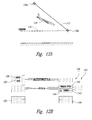
- Figure 13A is a pictorial illustration of an aircraft on an ILS approach
- Figure 13B illustrates a portion of a display having corresponding flight control information in accordance with an embodiment of the invention.
- Figure 3A is a schematic illustration of a system 100 installed on an aircraft 110 to automatically control functions of the aircraft operation and display information regarding the status of aircraft automatic controls in accordance with an embodiment of the invention.
- the information displayed by the system 100 can change location, depending upon the manner in which the aircraft is being controlled. Accordingly, the pilot can readily notice and understand changes in the status and operation of the automatic controls.
- the system 100 can include one or more computers 102 (schematically illustrated in Figure 3 as a single computer 102).
- the computer 102 can include a memory 103, a processor 105, and an input/output device 104.
- the computer 102 can be linked to one or more controllers 114, such as an engine controller or autothrottle 114a, a roll controller 114b, and a pitch controller 114c.
- the engine controller 114a can be operatively coupled to engines 111 of the aircraft 110 to automatically control engine functions, such as engine thrust.
- the roll controller 114b can be operatively coupled to ailerons 112 of the aircraft 110, and the pitch controller 114c can be operatively coupled to elevators 113 of the aircraft 110.
- the roll controller 114b and the pitch controller 114c can form a portion of an integrated autopilot device. In another embodiment, the roll controller 114b and the pitch controller 114c can be independent. In either embodiment, the controllers 114a-c can automatically control the aircraft thrust, roll, and pitch.
- the computer 102 can also be coupled to a display medium 106 which is configured to display to the pilot information corresponding to the operation of the controllers 114. Instructions for displaying the information on the display medium 106 can be stored in the memory 103 or any other computer readable medium, such as a medium accessible to the computer 102 via the input/output device 104.
- Figure 3B is a block diagram illustrating a process 170 carried out by the system 100 ( Figure 3A) in accordance with an embodiment of the invention.
- the process 170 can include receiving information corresponding to the operation of an automatic aircraft controller (process portion 172).
- the process can further include determining whether or not the automatic aircraft controller is controlling an aircraft function based at least in part on aircraft speed (process portion 174). If the automatic aircraft controller is controlling the aircraft function based at least in part on the aircraft speed, the process can further include displaying alphanumeric information corresponding to the operation of the aircraft controller at a first location of the display medium (process portion 176). Otherwise, the process can include displaying alphanumeric information corresponding to the operation of the aircraft controller at a second location of the display medium (process portion 178).
- the process 170 can include displaying aircraft speed at a first region of the display medium at least proximate to the first location (process portion 180).
- the process 170 can further include displaying aircraft altitude at a second region of the display medium at least proximate to the second location (process portion 182).
- this juxtaposition can provide visual cues to the pilot that indicate the manner in which the flight control devices are controlling the aircraft.
- Figure 3C illustrates another process 190 carried out by the system 100 described above with reference to Figure 3A in accordance with another embodiment of the invention.
- the process 190 can include receiving first information corresponding to the operation of an aircraft autothrottle and/or autopilot (process portion 191).
- the process 190 can further include displaying the first information at a first location of a display medium (process portion 192).
- the process 190 can still further include receiving second information corresponding to the operation of an aircraft engine (process portion 193) and displaying the second information at a second portion of the display medium at least proximate to the first portion (process portion 194).
- juxtaposing the information in this manner can make it easier for the pilot to assess the operating condition of the aircraft.
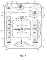
- FIG 4 is an enlarged illustration of an embodiment of the display medium 106 described above with reference to Figure 3A.
- the display medium 106 can present a display 130 having a variety of fields or regions at which information regarding the operation of the automatic flight control devices appears.
- the display medium 106 can include a CRT device.
- the display medium 106 can include an LCD device.
- the display medium 106 can include other devices, such as a head-up display (HUD) device.
- the display medium 106 can include a single device on which the entire display 130 appears, or the display medium 106 can include a plurality of closely-spaced devices (such as closely-spaced LCD panels) which together present the entire display 130.
- HUD head-up display
- the display 130 can include a first region 131 elongated along a first longitudinal axis 137a, and a second region 132 elongated along a second longitudinal axis 137b.
- An aircraft speed display 133 can be positioned in the first region 131, and an aircraft altitude display 134 can be positioned in the second region 132.
- An aircraft attitude display 135 and heading display 136 can be positioned between the first region 131 and the second region 132.
- the display 130 can include a pitch mode display 140 and a roll mode display 165 that together describe the function of an aircraft autopilot (e.g., the roll controller 114b and pitch controller 114c described above with reference to Figure 3A).
- the roll mode display 165 can include a roll mode indicator 166 that displays text corresponding to a preselected mode of roll control.
- the display 130 can also include an autothrottle mode display 150 that describes the function of the aircraft autothrottle (e.g., the engine controller 114a described above with reference to Figure 3).
- the autothrottle mode display 150 can have a thrust display portion 160 that has a graphical and/or textual illustration of the thrust limit 162 and the actual thrust 161 applied to the aircraft engines 111 ( Figure 3A).
- the information corresponding to the operation of the automatic flight control devices can shift from one portion of the display 130 to another depending on whether or not the flight control device is controlling the aircraft (at least in part) on the basis of a target speed.
- the pitch mode display 140 can include a first pitch mode location 141 and a second pitch mode location 142.
- the autothrottle mode display 150 can include a first autothrottle mode location 151 and a second autothrottle mode location 152.
- the first pitch mode location 141 and the first autothrottle mode location 151 are axially aligned with the first region 131
- the second pitch mode location 142 and the second autothrottle mode location 152 are axially aligned with the second region 132.
- information can be displayed at the first locations 141 and/or 151 when the operations of the corresponding control devices are based at least in part on aircraft speed.
- Information can be displayed at the second locations 142 and/or 152 when the operations of the corresponding control devices are not based at least in part on aircraft speed, for example, when these operations are based at least in part on aircraft altitude.
- the autothrottle mode display 150 can be positioned above the pitch mode display 140. In another embodiment, the relative positions of the autothrottle mode display 150 and the pitch mode display 140 can be reversed. In either embodiment, the autothrottle mode display 150 and the pitch mode display 140 can each present alphanumeric information corresponding to the operation of the autothrottle and the autopilot, respectively.
- the autothrottle mode display 150 can include an autothrottle mode indicator 155 that presents (when applicable) information corresponding to which of a number of predefined modes the autothrottle is operating in.
- the autothrottle mode display 150 can further include a target speed indicator 153 that presents (when applicable) the aircraft speed that the autothrottle attempts to maintain as it adjusts engine thrust.
- the autothrottle mode indicator 155 displays mode "SPD" and the target speed indicator 153 displays a target speed of 140 knots.
- the pitch mode display 140 can include a pitch mode indicator 145 that presents (when applicable) information corresponding to which of a number of preselected modes the pitch controller is operating in.
- the pitch mode display 140 can further include a pitch direction indicator 144 that indicates whether the aircraft is gaining or losing altitude, and a target altitude indicator 143 that presents the aircraft altitude that the pitch controller attempts to maintain or achieve as it adjusts the aircraft elevator position.
- the pitch mode indicator displays pitch mode "G/S" (glide slope)
- the pitch direction indicator 144 displays a downward arrow to indicate descent
- the altitude indicator displays a target altitude of 100 feet.
- Some or all of the foregoing alphanumeric information can shift from a position aligned with the first region 131 to a position aligned with the second region 132, depending upon what the corresponding flight control device is controlling to.
- the autothrottle can control to a target speed of 140 knots and the pitch controller can control the aircraft to descend to 100 feet.
- the autothrottle mode indicator 155 and the target speed indicator 153 are aligned with the first region 131 (which displays aircraft speed)
- the pitch mode indicator 145, target altitude indicator 143, and pitch direction indicator 144 are aligned with the second region 132 (which displays aircraft altitude).
- the pilot can accordingly receive a visual cue that, in autothrottle mode "SPD," it is the autothrottle rather than the autopilot that is controlling to a target aircraft speed.
- Figures 5A-13B below illustrate representative modes for both the autothrottle and the pitch controller in accordance with further embodiments of the invention.
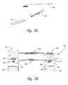
- Figure 5A is a pictorial illustration of an aircraft 110 that has departed from a runway 115 in a full-power climb to a target altitude of 4,000 feet, indicated by target altitude line 116.
- Figure 5B illustrates a portion of the display 130 described above with reference to Figure 4, with the automatic flight control information as it appears during this portion of the flight.
- the thrust display 160 ( Figure 4) and the roll mode display 165 ( Figure 4) are not shown in Figure 5B.
- the pitch mode indicator 145 has the text "TO/GA" (take-off/go-around) to indicate the pitch mode
- the target speed indicator 153 indicates that the aircraft elevators are being controlled to match a target airspeed of 165 knots.
- Both the pitch mode indicator 145 and the target speed indicator 153 are positioned in the first pitch mode location 141 (aligned with the aircraft speed display 133) to indicate that the pitch is being controlled to match a target aircraft speed.
- the pitch direction indicator 144 indicates that the aircraft is climbing
- the target altitude indicator 143 indicates that the climb is to a target altitude of 4,000 feet.
- the autothrottle mode indicator 155 displays the text "THR REF" (reference thrust).
- the autothrottle mode indicator 155 has shifted away from the first autothrottle mode location 151 (aligned with the aircraft speed display 133), to the second autothrottle mode location 152. Accordingly, the pilot receives a visual cue that it is the autopilot, not the autothrottle, that is controlling to an aircraft speed.
- the autothrottle mode display 150 can include an autothrottle display label 156
- the pitch mode display 140 can include a pitch display label 146, each positioned to identify the function of the respective mode display.
- the labels 156 and 146 can be eliminated.
- Figure 6A illustrates the aircraft 110 climbing at partial power to 4,000 feet, as indicated by target altitude line 116.
- Figure 6B illustrates a corresponding portion of the display 130.
- the autothrottle mode indicator 155 indicates mode "THR.”
- the pitch mode indicator 145 indicates mode "FLCH SPD.”
- the aircraft is controlled to a target speed of 220 knots, as indicated by the target speed indicator 153. Because the target speed indicator 153 appears at the first pitch mode location 141 (rather than the first autothrottle mode location 151), the pilot receives a visual cue that the pitch controller (and not the autothrottle) is controlling to the target speed.
- the aircraft 110 can climb at a constant airspeed and a constant altitude change rate (or vertical speed) to a target altitude of 4,000 feet, as indicated by target altitude line 116.
- the target speed indicator 153 indicates that the autothrottle is controlling to a target speed of 220 knots
- the autothrottle mode indicator 155 indicates that the autothrottle is in mode "SPD.”
- the pitch controller is controlling the elevators of the aircraft to a target altitude change rate of 1,000 feet per minute, as indicated by the text "V/S" at the pitch mode indicator 145, and the numeral 1,000 at a target altitude change rate indicator 147.
- the pilot Because the target speed indicator 153 appears at the autothrottle mode display 150, and because the autothrottle mode indicator 155 is aligned with the aircraft speed display 133, the pilot receives visual cues that the autothrottle is controlling to aircraft speed. Because the pitch mode indicator 145 is aligned with the aircraft altitude display 134, the pilot receives a visual cue that the pitch controller is controlling to a target altitude and altitude change rate.
- Figure 8A illustrates the aircraft 110 flying level at a target altitude of 12,000 feet, indicated by the target altitude line 116.
- Figure 8B illustrates a portion of the corresponding display 130, in which the autothrottle mode indicator 155 displays mode "SPD" and the target speed indicator 153 indicates that the autothrottle is controlling to a target speed of 300 knots.
- the target altitude indicator 143 indicates that the pitch controller is controlling to a target altitude of 12,000 feet, and the pitch mode indicator 145 indicates pitch mode "ALT."
- the pilot receives visual cues as to the manner in which the aircraft is being flown to achieve and/or maintain flight targets.
- Figure 9A illustrates the aircraft 110 in a descent to 15,000 feet, as indicated by the target altitude line 116.
- Figure 9B illustrates a portion of the corresponding display 130.
- the pitch direction indicator 144 displays a downward pointing arrow and the target altitude indicator 143 indicates a target altitude of 15,000 feet.
- the pitch mode indicator 145 displays mode "FLCH SPD" aligned with the aircraft speed display 133, with the elevators controlled to a target air speed of 280 knots, as indicated by the target speed indicator 153.
- the autothrottle mode display 150 has the autothrottle mode indicator 155 indicating mode "THR,” aligned with the aircraft altitude display 134.
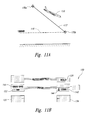
- Figure 10A illustrates the aircraft 110 descending along a geometric path 117 between a first fixed point 170a and a second fixed point 170b to a target altitude of 12,000 feet, as indicated by target altitude line 116.
- the autothrottle mode indicator 155 indicates the engines at "IDLE” mode for this flight segment. After a predetermined period of time, the autothrottle can go “dormant” and the autothrottle mode indicator 155 can indicate a "HOLD" mode.
- the pitch direction indicator 144 indicates that the aircraft is descending, and the target altitude indicator 143 indicates that the target altitude is 12,000 feet.
- the pitch mode indicator 145 indicates a pitch mode of "VNAV PTH," which is aligned with the aircraft altitude display 134.
- the pilot By aligning both the autothrottle mode indicator 155 and the pitch mode indicator 145 with the altitude display 134, the pilot receives a visual cue that neither the autothrottle nor the pitch controller are controlling to a target aircraft speed, but are instead controlling the aircraft to a target flight path.
- the pitch controller shifts from controlling to the target flight path 117 (as was indicated by the pitch mode "VNAV PTH" shown in Figure 10B) to pitch mode "VNAV SPD,” as shown in Figure 11B.
- a target airspeed of 300 knots also appears at the target airspeed indicator 153.
- Both the pitch mode indicator 145 and the target airspeed indicator 153 are aligned with the aircraft speed display 133 to indicate to the pilot that the aircraft 110 is no longer being controlled to a target flight path, and is instead being controlled to a target speed. This situation (commonly referred to as "speed reversion”) may occur if the winds change unexpectedly during descent.
- the pitch controller can remain in the "VNAV PTH" mode described above with reference to Figure 10B.
- the autothrottle can "awaken” out of the dormant ("HOLD") mode to increase the aircraft speed to the original speed upon which the target flight path 117 was calculated.
- the autothrottle mode indicator 155 indicates mode "SPD”
- the target airspeed indicator 153 (now positioned at the autothrottle mode display 150) indicates the autothrottle controlling to a target airspeed of 300 knots.
- Figure 13A illustrates the aircraft 110 on approach along an ILS (instrument landing system) glide slope 118.
- the display 130 can indicate autothrottle mode "SPD" at the autothrottle mode indicator 155, and a target speed of 145 knots at the target speed indicator 153.
- the pitch mode indicator 145 can display the mode "G/S" (glide slope), without indicating a target altitude because the autopilot is not controlling to a target altitude.
- the pitch mode display 140 can include a missed approach altitude indicator 148, indicating a missed approach altitude of 4,000 feet.
- the alphanumeric indicators for the flight control modes and the targets to which the flight control devices are controlling can shift position on the display 130, depending upon whether or not the flight control device is controlling to an aircraft speed. Accordingly, both the content and the display location of the alphanumeric information can change when the operational mode of the flight control device changes.
- An advantage of this feature is that it can provide an intuitive, visual link for the pilot and can help the pilot understand what the flight control devices are doing.
- a further advantage of this feature is that when the flight control devices change the manner in which they operate, this change is more noticeable to the pilot because the position of the mode description changes, also in a way that creates an intuitive link between the mode and the variable (typically airspeed, altitude, or altitude change rate) to which the flight control device is controlling.
- the variable typically airspeed, altitude, or altitude change rate
- the display 130 can include a thrust display 160 that indicates the present thrust limit (as a percentage of the total available thrust), and the actual thrust (also as a percentage of the total available thrust).
- the thrust information can be displayed textually and/or graphically, and in other embodiments, this information can be represented in other manners.
- the pilot can more quickly assess the overall performance level of the aircraft's entire propulsion system.
- Another advantage of this feature is that the engine performance information can be displayed proximate to the autothrottle and/or autopilot information. Accordingly, the pilot can more easily obtain a comprehensive indication of aircraft performance from a visually compact source, without moving his or her eyes over significant distances.
- control devices can control aircraft functions other than aircraft pitch, roll, and thrust, and can have modes other than those described above with reference to Figures 3A-13B. Accordingly, the invention is not limited except as by the appended claims.
Abstract
Description
- The present invention relates generally to methods and apparatuses for displaying autoflight information, such as autothrottle and/or autopilot mode information.
- Modern commercial transport aircraft are controlled by automatic flight control devices during many and sometimes all segments of a typical flight. The automatic flight control devices typically include an autothrottle that controls engine thrust, and an autopilot that controls both pitch attitude (via the aircraft elevators) and roll attitude (via the aircraft ailerons). Information regarding the status and activities of the flight control devices is typically displayed on a display device, such as a CRT, LCD or other graphical user interface.
- Figure 1 illustrates a
typical display device 10 that presents adisplay 30 in accordance with the prior art. Thedisplay 30 includes anair speed display 33, analtitude display 34, anattitude display 35, and aheading display 36. Thedisplay 30 also includes a series of annunciators, each indicating (via a textual shorthand) which of a variety of pre-defined modes a corresponding one of the automatic flight control devices is operating in. For example, thedisplay 30 can include anautothrottle mode annunciator 55, aroll mode annunciator 66, and apitch mode annunciator 45. In the particular configuration shown in Figure 1, "SPD" indicates that the aircraft autothrottle is controlling the engine thrust based on a target aircraft speed. "LOC" indicates that the roll control portion of the autopilot is controlling to maintain a track on a localizer beam, and "G/S" indicates that the pitch control portion of the autopilot is controlling the elevators based on a target glide slope. - Figure 2 illustrates a
separate display device 10a that presents anengine indication display 60 in accordance with the prior art. Thedisplay 60 can include graphical depictions of the exhaust pressure ratio (EPR), engine RPM (N1) and exhaust gas temperature (EGT) for each engine. Thedisplay 60 can also include a textualthrust limit indicator 62a, a numericalthrust limit indicator 62b, and a numericalactual thrust indicator 61. - One drawback with the
display 30 described above with reference to Figure 1 is that the mode annunciators are relatively cryptic and require the pilot to memorize the type of action performed by each flight control device in each mode. A drawback with theengine indication display 60 shown in Figure 2 is that it requires the pilot to look at a separate display for engine information. Accordingly, the pilot may need to move his or her eyes back and forth between multiple displays to understand various aspects of the flight control operation. - The present invention is directed toward methods and systems for displaying information corresponding to the operation of automatic aircraft controllers. The method can be implemented on a computer, a computer readable medium, or a computer system. For example, if the automatic aircraft controller is controlling an aircraft function based at least in part on a target aircraft speed, the method can include displaying alphanumeric information corresponding to the operation of the automatic aircraft controller at a first location of a display medium. The method can further include (if the automatic aircraft controller is not controlling the aircraft function based at least in part on the target aircraft speed), displaying the alphanumeric information at a second location of the display medium different than the first location.
- In a further aspect of the invention, the method can include displaying an aircraft speed at a first region of the display medium and displaying an aircraft altitude at a second region of the display medium different than the first region. Displaying the alphanumeric information at the first location can include displaying at least a portion of the alphanumeric information at least proximate to the first region of the display medium, and displaying the alphanumeric information at the second location can include displaying at least a portion of the alphanumeric information at least proximate to the second region of the display medium. In one aspect of the invention, the automatic aircraft controller can include an autopilot, and in another aspect of the invention, the automatic aircraft controller can include an autothrottle. In still a further aspect of the invention, the automatic aircraft controller can operate according to a plurality of predetermined modes, and displaying alphanumeric information can include displaying alphanumeric information corresponding to an identity of at least one of the modes.
- A method in accordance with another aspect of the invention includes displaying information corresponding to the operation of an aircraft engine. The method can include displaying on a display medium first information corresponding to an operation of at least one of an aircraft autopilot and an aircraft autothrottle. The method can further include displaying on the display medium second information corresponding to a performance of an aircraft engine, with the second information being positioned at least proximate to the first information on the display medium. In a further aspect of the invention, the second information can include at least one of a thrust limit and an actual thrust level, and in yet a further aspect, the second information can include a graphical representation of the actual thrust level.
- Figure 1 illustrates a flight display in accordance with the prior art.
- Figure 2 illustrates an engine indication display in accordance with the prior art.
- Figure 3A is a schematic illustration of a system for controlling aircraft functions in accordance with an embodiment of the invention.
- Figure 3B is a block diagram illustrating processes performed by a system in accordance with an embodiment of the invention.
- Figure 3C is a block diagram illustrating processes performed by a system in accordance with another embodiment of the invention.
- Figure 4 is a partially schematic illustration of a display arranged in accordance with an embodiment of the invention.
- Figure 5A is a pictorial illustration of an aircraft in a full power climb, and Figure 5B illustrates a portion of a display having corresponding flight control information in accordance with an embodiment of the invention.
- Figure 6A is a pictorial illustration of an aircraft in a partial power climb, and Figure 6B illustrates a portion of a display having corresponding flight control information in accordance with an embodiment of the invention.
- Figure 7A is a pictorial illustration of an aircraft climbing at a constant air speed and constant vertical speed, and Figure 7B illustrates a portion of a display having corresponding flight control information in accordance with an embodiment of the invention.
- Figure 8A is a pictorial illustration of an aircraft operating at a constant altitude, and Figure 8B illustrates a portion of a display having corresponding flight control information in accordance with an embodiment of the invention.
- Figure 9A is a pictorial illustration of an aircraft in a partial power descent, and Figure 9B illustrates a portion of a display having corresponding flight control information in accordance with an embodiment of the invention.
- Figure 10A is a pictorial illustration of an aircraft flying a pre-planned geometric descent path, and Figure 10B illustrates a portion of a display having corresponding flight control information in accordance with an embodiment of the invention.
- Figure 11A is a pictorial illustration of an aircraft that has deviated above a pre-planned geometric descent path, and Figure 11B illustrates a portion of a display having corresponding flight control information in accordance with an embodiment of the invention.
- Figure 12A is a pictorial illustration of an aircraft that has fallen below a pre-planned geometric path, and Figure 12B illustrates a portion of a display having corresponding flight control information in accordance with an embodiment of the invention.
- Figure 13A is a pictorial illustration of an aircraft on an ILS approach, and Figure 13B illustrates a portion of a display having corresponding flight control information in accordance with an embodiment of the invention.
- The present disclosure describes systems and methods for displaying flight control information. Many specific details of certain embodiments of the invention are set forth in the following description and in Figures 3A-13B to provide a thorough understanding of these embodiments. However, the present invention can have additional embodiments, and may be practiced without several of the details described below.
- Figure 3A is a schematic illustration of a
system 100 installed on anaircraft 110 to automatically control functions of the aircraft operation and display information regarding the status of aircraft automatic controls in accordance with an embodiment of the invention. The information displayed by thesystem 100 can change location, depending upon the manner in which the aircraft is being controlled. Accordingly, the pilot can readily notice and understand changes in the status and operation of the automatic controls. - In one aspect of this embodiment, the
system 100 can include one or more computers 102 (schematically illustrated in Figure 3 as a single computer 102). Thecomputer 102 can include amemory 103, aprocessor 105, and an input/output device 104. Thecomputer 102 can be linked to one or more controllers 114, such as an engine controller orautothrottle 114a, aroll controller 114b, and apitch controller 114c. Theengine controller 114a can be operatively coupled toengines 111 of theaircraft 110 to automatically control engine functions, such as engine thrust. Theroll controller 114b can be operatively coupled toailerons 112 of theaircraft 110, and thepitch controller 114c can be operatively coupled toelevators 113 of theaircraft 110. In one embodiment, theroll controller 114b and thepitch controller 114c can form a portion of an integrated autopilot device. In another embodiment, theroll controller 114b and thepitch controller 114c can be independent. In either embodiment, thecontrollers 114a-c can automatically control the aircraft thrust, roll, and pitch. - The
computer 102 can also be coupled to adisplay medium 106 which is configured to display to the pilot information corresponding to the operation of the controllers 114. Instructions for displaying the information on thedisplay medium 106 can be stored in thememory 103 or any other computer readable medium, such as a medium accessible to thecomputer 102 via the input/output device 104. - Figure 3B is a block diagram illustrating a
process 170 carried out by the system 100 (Figure 3A) in accordance with an embodiment of the invention. In one aspect of this embodiment, theprocess 170 can include receiving information corresponding to the operation of an automatic aircraft controller (process portion 172). The process can further include determining whether or not the automatic aircraft controller is controlling an aircraft function based at least in part on aircraft speed (process portion 174). If the automatic aircraft controller is controlling the aircraft function based at least in part on the aircraft speed, the process can further include displaying alphanumeric information corresponding to the operation of the aircraft controller at a first location of the display medium (process portion 176). Otherwise, the process can include displaying alphanumeric information corresponding to the operation of the aircraft controller at a second location of the display medium (process portion 178). - In another aspect of this embodiment, the
process 170 can include displaying aircraft speed at a first region of the display medium at least proximate to the first location (process portion 180). Theprocess 170 can further include displaying aircraft altitude at a second region of the display medium at least proximate to the second location (process portion 182). As described in greater detail below with reference to Figures 4-13B, this juxtaposition can provide visual cues to the pilot that indicate the manner in which the flight control devices are controlling the aircraft. - Figure 3C illustrates another
process 190 carried out by thesystem 100 described above with reference to Figure 3A in accordance with another embodiment of the invention. In one aspect of this embodiment, theprocess 190 can include receiving first information corresponding to the operation of an aircraft autothrottle and/or autopilot (process portion 191). Theprocess 190 can further include displaying the first information at a first location of a display medium (process portion 192). Theprocess 190 can still further include receiving second information corresponding to the operation of an aircraft engine (process portion 193) and displaying the second information at a second portion of the display medium at least proximate to the first portion (process portion 194). As described in greater detail below with reference to Figures 4-13B, juxtaposing the information in this manner can make it easier for the pilot to assess the operating condition of the aircraft. - Figure 4 is an enlarged illustration of an embodiment of the
display medium 106 described above with reference to Figure 3A. Thedisplay medium 106 can present adisplay 130 having a variety of fields or regions at which information regarding the operation of the automatic flight control devices appears. In one embodiment, thedisplay medium 106 can include a CRT device. In another embodiment, thedisplay medium 106 can include an LCD device. In still further embodiments, thedisplay medium 106 can include other devices, such as a head-up display (HUD) device. In any of these embodiments, thedisplay medium 106 can include a single device on which theentire display 130 appears, or thedisplay medium 106 can include a plurality of closely-spaced devices (such as closely-spaced LCD panels) which together present theentire display 130. Thedisplay 130 can include afirst region 131 elongated along a firstlongitudinal axis 137a, and asecond region 132 elongated along a secondlongitudinal axis 137b. Anaircraft speed display 133 can be positioned in thefirst region 131, and anaircraft altitude display 134 can be positioned in thesecond region 132. Anaircraft attitude display 135 and headingdisplay 136 can be positioned between thefirst region 131 and thesecond region 132. - In one embodiment, the
display 130 can include apitch mode display 140 and aroll mode display 165 that together describe the function of an aircraft autopilot (e.g., theroll controller 114b andpitch controller 114c described above with reference to Figure 3A). Theroll mode display 165 can include aroll mode indicator 166 that displays text corresponding to a preselected mode of roll control. Thedisplay 130 can also include anautothrottle mode display 150 that describes the function of the aircraft autothrottle (e.g., theengine controller 114a described above with reference to Figure 3). Theautothrottle mode display 150 can have athrust display portion 160 that has a graphical and/or textual illustration of thethrust limit 162 and theactual thrust 161 applied to the aircraft engines 111 (Figure 3A). - The information corresponding to the operation of the automatic flight control devices can shift from one portion of the
display 130 to another depending on whether or not the flight control device is controlling the aircraft (at least in part) on the basis of a target speed. Accordingly, thepitch mode display 140 can include a firstpitch mode location 141 and a secondpitch mode location 142. Theautothrottle mode display 150 can include a firstautothrottle mode location 151 and a secondautothrottle mode location 152. In one aspect of an embodiment shown in Figure 4, the firstpitch mode location 141 and the firstautothrottle mode location 151 are axially aligned with thefirst region 131, and the secondpitch mode location 142 and the secondautothrottle mode location 152 are axially aligned with thesecond region 132. Accordingly, information can be displayed at thefirst locations 141 and/or 151 when the operations of the corresponding control devices are based at least in part on aircraft speed. Information can be displayed at thesecond locations 142 and/or 152 when the operations of the corresponding control devices are not based at least in part on aircraft speed, for example, when these operations are based at least in part on aircraft altitude. - In one aspect of an embodiment of the
display 130 shown in Figure 4, theautothrottle mode display 150 can be positioned above thepitch mode display 140. In another embodiment, the relative positions of theautothrottle mode display 150 and thepitch mode display 140 can be reversed. In either embodiment, theautothrottle mode display 150 and thepitch mode display 140 can each present alphanumeric information corresponding to the operation of the autothrottle and the autopilot, respectively. For example, theautothrottle mode display 150 can include anautothrottle mode indicator 155 that presents (when applicable) information corresponding to which of a number of predefined modes the autothrottle is operating in. Theautothrottle mode display 150 can further include atarget speed indicator 153 that presents (when applicable) the aircraft speed that the autothrottle attempts to maintain as it adjusts engine thrust. In the example shown in Figure 4, theautothrottle mode indicator 155 displays mode "SPD" and thetarget speed indicator 153 displays a target speed of 140 knots. - The
pitch mode display 140 can include apitch mode indicator 145 that presents (when applicable) information corresponding to which of a number of preselected modes the pitch controller is operating in. Thepitch mode display 140 can further include apitch direction indicator 144 that indicates whether the aircraft is gaining or losing altitude, and atarget altitude indicator 143 that presents the aircraft altitude that the pitch controller attempts to maintain or achieve as it adjusts the aircraft elevator position. In the example shown in Figure 4, the pitch mode indicator displays pitch mode "G/S" (glide slope), thepitch direction indicator 144 displays a downward arrow to indicate descent, and the altitude indicator displays a target altitude of 100 feet. - Some or all of the foregoing alphanumeric information can shift from a position aligned with the
first region 131 to a position aligned with thesecond region 132, depending upon what the corresponding flight control device is controlling to. For example, as shown in Figure 4, the autothrottle can control to a target speed of 140 knots and the pitch controller can control the aircraft to descend to 100 feet. Accordingly, theautothrottle mode indicator 155 and thetarget speed indicator 153 are aligned with the first region 131 (which displays aircraft speed), and thepitch mode indicator 145,target altitude indicator 143, andpitch direction indicator 144 are aligned with the second region 132 (which displays aircraft altitude). The pilot can accordingly receive a visual cue that, in autothrottle mode "SPD," it is the autothrottle rather than the autopilot that is controlling to a target aircraft speed. Figures 5A-13B below illustrate representative modes for both the autothrottle and the pitch controller in accordance with further embodiments of the invention. - Figure 5A is a pictorial illustration of an
aircraft 110 that has departed from arunway 115 in a full-power climb to a target altitude of 4,000 feet, indicated bytarget altitude line 116. Figure 5B illustrates a portion of thedisplay 130 described above with reference to Figure 4, with the automatic flight control information as it appears during this portion of the flight. For purposes of illustration, the thrust display 160 (Figure 4) and the roll mode display 165 (Figure 4) are not shown in Figure 5B. Thepitch mode indicator 145 has the text "TO/GA" (take-off/go-around) to indicate the pitch mode, and thetarget speed indicator 153 indicates that the aircraft elevators are being controlled to match a target airspeed of 165 knots. Both thepitch mode indicator 145 and thetarget speed indicator 153 are positioned in the first pitch mode location 141 (aligned with the aircraft speed display 133) to indicate that the pitch is being controlled to match a target aircraft speed. Thepitch direction indicator 144 indicates that the aircraft is climbing, and thetarget altitude indicator 143 indicates that the climb is to a target altitude of 4,000 feet. - The
autothrottle mode indicator 155 displays the text "THR REF" (reference thrust). Theautothrottle mode indicator 155 has shifted away from the first autothrottle mode location 151 (aligned with the aircraft speed display 133), to the secondautothrottle mode location 152. Accordingly, the pilot receives a visual cue that it is the autopilot, not the autothrottle, that is controlling to an aircraft speed. - In another aspect of an embodiment shown in Figure 5B, the
autothrottle mode display 150 can include anautothrottle display label 156, and thepitch mode display 140 can include apitch display label 146, each positioned to identify the function of the respective mode display. In another embodiment (such as that described above with reference to Figure 4), thelabels - Figure 6A illustrates the
aircraft 110 climbing at partial power to 4,000 feet, as indicated bytarget altitude line 116. Figure 6B illustrates a corresponding portion of thedisplay 130. Because the aircraft is at partial power, theautothrottle mode indicator 155 indicates mode "THR." Thepitch mode indicator 145 indicates mode "FLCH SPD." The aircraft is controlled to a target speed of 220 knots, as indicated by thetarget speed indicator 153. Because thetarget speed indicator 153 appears at the first pitch mode location 141 (rather than the first autothrottle mode location 151), the pilot receives a visual cue that the pitch controller (and not the autothrottle) is controlling to the target speed. - In another embodiment, shown in Figures 7A and 7B, the
aircraft 110 can climb at a constant airspeed and a constant altitude change rate (or vertical speed) to a target altitude of 4,000 feet, as indicated bytarget altitude line 116. Accordingly, thetarget speed indicator 153 indicates that the autothrottle is controlling to a target speed of 220 knots, and theautothrottle mode indicator 155 indicates that the autothrottle is in mode "SPD." The pitch controller is controlling the elevators of the aircraft to a target altitude change rate of 1,000 feet per minute, as indicated by the text "V/S" at thepitch mode indicator 145, and the numeral 1,000 at a target altitudechange rate indicator 147. Because thetarget speed indicator 153 appears at theautothrottle mode display 150, and because theautothrottle mode indicator 155 is aligned with theaircraft speed display 133, the pilot receives visual cues that the autothrottle is controlling to aircraft speed. Because thepitch mode indicator 145 is aligned with theaircraft altitude display 134, the pilot receives a visual cue that the pitch controller is controlling to a target altitude and altitude change rate. - Figure 8A illustrates the
aircraft 110 flying level at a target altitude of 12,000 feet, indicated by thetarget altitude line 116. Figure 8B illustrates a portion of thecorresponding display 130, in which theautothrottle mode indicator 155 displays mode "SPD" and thetarget speed indicator 153 indicates that the autothrottle is controlling to a target speed of 300 knots. Thetarget altitude indicator 143 indicates that the pitch controller is controlling to a target altitude of 12,000 feet, and thepitch mode indicator 145 indicates pitch mode "ALT." Again, because theautothrottle mode indicator 155 is aligned with theaircraft speed display 133, and thepitch mode indicator 145 is aligned with theaircraft altitude display 134, the pilot receives visual cues as to the manner in which the aircraft is being flown to achieve and/or maintain flight targets. - Figure 9A illustrates the
aircraft 110 in a descent to 15,000 feet, as indicated by thetarget altitude line 116. Figure 9B illustrates a portion of thecorresponding display 130. Thepitch direction indicator 144 displays a downward pointing arrow and thetarget altitude indicator 143 indicates a target altitude of 15,000 feet. Thepitch mode indicator 145 displays mode "FLCH SPD" aligned with theaircraft speed display 133, with the elevators controlled to a target air speed of 280 knots, as indicated by thetarget speed indicator 153. Theautothrottle mode display 150 has theautothrottle mode indicator 155 indicating mode "THR," aligned with theaircraft altitude display 134. - Figure 10A illustrates the
aircraft 110 descending along ageometric path 117 between a firstfixed point 170a and a secondfixed point 170b to a target altitude of 12,000 feet, as indicated bytarget altitude line 116. As shown in Figure 10B, theautothrottle mode indicator 155 indicates the engines at "IDLE" mode for this flight segment. After a predetermined period of time, the autothrottle can go "dormant" and theautothrottle mode indicator 155 can indicate a "HOLD" mode. Thepitch direction indicator 144 indicates that the aircraft is descending, and thetarget altitude indicator 143 indicates that the target altitude is 12,000 feet. Thepitch mode indicator 145 indicates a pitch mode of "VNAV PTH," which is aligned with theaircraft altitude display 134. By aligning both theautothrottle mode indicator 155 and thepitch mode indicator 145 with thealtitude display 134, the pilot receives a visual cue that neither the autothrottle nor the pitch controller are controlling to a target aircraft speed, but are instead controlling the aircraft to a target flight path. - If the
aircraft 110 begins to overshoot the target flight path 117 (as indicated in Figure 11A), the pitch controller shifts from controlling to the target flight path 117 (as was indicated by the pitch mode "VNAV PTH" shown in Figure 10B) to pitch mode "VNAV SPD," as shown in Figure 11B. A target airspeed of 300 knots also appears at thetarget airspeed indicator 153. Both thepitch mode indicator 145 and thetarget airspeed indicator 153 are aligned with theaircraft speed display 133 to indicate to the pilot that theaircraft 110 is no longer being controlled to a target flight path, and is instead being controlled to a target speed. This situation (commonly referred to as "speed reversion") may occur if the winds change unexpectedly during descent. - If the
aircraft 110 falls below the target flight path 117 (as indicated in Figure 12A), the pitch controller can remain in the "VNAV PTH" mode described above with reference to Figure 10B. The autothrottle can "awaken" out of the dormant ("HOLD") mode to increase the aircraft speed to the original speed upon which thetarget flight path 117 was calculated. Accordingly, theautothrottle mode indicator 155 indicates mode "SPD," and the target airspeed indicator 153 (now positioned at the autothrottle mode display 150) indicates the autothrottle controlling to a target airspeed of 300 knots. - Figure 13A illustrates the
aircraft 110 on approach along an ILS (instrument landing system)glide slope 118. As shown in Figure 13B, thedisplay 130 can indicate autothrottle mode "SPD" at theautothrottle mode indicator 155, and a target speed of 145 knots at thetarget speed indicator 153. Thepitch mode indicator 145 can display the mode "G/S" (glide slope), without indicating a target altitude because the autopilot is not controlling to a target altitude. However, thepitch mode display 140 can include a missedapproach altitude indicator 148, indicating a missed approach altitude of 4,000 feet. - One feature of the foregoing embodiments described above with reference to Figures 3A-13B is that the alphanumeric indicators for the flight control modes and the targets to which the flight control devices are controlling can shift position on the
display 130, depending upon whether or not the flight control device is controlling to an aircraft speed. Accordingly, both the content and the display location of the alphanumeric information can change when the operational mode of the flight control device changes. An advantage of this feature is that it can provide an intuitive, visual link for the pilot and can help the pilot understand what the flight control devices are doing. A further advantage of this feature is that when the flight control devices change the manner in which they operate, this change is more noticeable to the pilot because the position of the mode description changes, also in a way that creates an intuitive link between the mode and the variable (typically airspeed, altitude, or altitude change rate) to which the flight control device is controlling. - Another feature of embodiments of the systems and methods described above with reference to Figures 3A-4 is that information corresponding to the performance of the aircraft engine(s) can be displayed proximate to information corresponding to the operation of the autothrottle and/or the autopilot. For example, the
display 130 can include athrust display 160 that indicates the present thrust limit (as a percentage of the total available thrust), and the actual thrust (also as a percentage of the total available thrust). In one aspect of this embodiment, the thrust information can be displayed textually and/or graphically, and in other embodiments, this information can be represented in other manners. One advantage of this feature is that the performance characteristics for a multi-engine aircraft can be presented in a single, composite display. Accordingly, the pilot can more quickly assess the overall performance level of the aircraft's entire propulsion system. Another advantage of this feature is that the engine performance information can be displayed proximate to the autothrottle and/or autopilot information. Accordingly, the pilot can more easily obtain a comprehensive indication of aircraft performance from a visually compact source, without moving his or her eyes over significant distances. - From the foregoing, it will be appreciated that specific embodiments of the invention have been described herein for purposes of illustration, but that various modifications may be made without deviating from the spirit and scope of the invention. For example, the control devices can control aircraft functions other than aircraft pitch, roll, and thrust, and can have modes other than those described above with reference to Figures 3A-13B. Accordingly, the invention is not limited except as by the appended claims.
Claims (23)
- A computer-implemented method for displaying information corresponding to the operation of an automatic aircraft controller, comprising:if the automatic aircraft controller is controlling an aircraft function based at least in part on a target aircraft speed, displaying alphanumeric information corresponding to the operation of the automatic aircraft controller at a first location of a display medium; andif the automatic aircraft controller is not controlling the aircraft function based at least in part on the target aircraft speed, displaying the alphanumeric information at a second location of the display medium different than the first location.
- The method of claim 1 wherein displaying the alphanumeric information at the second location of the display medium includes displaying the alphanumeric information at the second location if the automatic aircraft controller controls the aircraft function based at least in part on a target aircraft altitude and/or a target aircraft altitude change rate.
- The method of claim 1, further comprising:wherein displaying the alphanumeric information at the first location includes displaying at least a portion of the alphanumeric information at least proximate to the first region of the display medium and wherein displaying the alphanumeric information at the second location includes displaying at least a portion of the alphanumeric information at least proximate to the second region of the display medium.displaying an aircraft speed at a first region of the display medium;displaying an aircraft altitude at a second region of a display medium different than the first region of the display medium; and
- The method of claim 1, 2 or 3 further comprising displaying an aircraft speed at a first region of the display medium, the first region being elongated along an axis, and wherein displaying the alphanumeric information includes displaying at least a portion of the alphanumeric information aligned with the longitudinal axis.
- The method of any of claims 1-4 wherein the automatic aircraft controller includes an aircraft autopilot configured to control aircraft pitch, and wherein displaying alphanumeric information corresponding to the operation of the automatic aircraft controller includes displaying alphanumeric information corresponding to the operation of the aircraft autopilot.
- The method of any of claims 1-5 wherein the automatic aircraft controller includes an aircraft autothrottle configured to control aircraft engine thrust, and wherein displaying alphanumeric information corresponding to the operation of the automatic aircraft controller includes displaying alphanumeric information corresponding to the operation of the aircraft autothrottle.
- The method of any of claims 1-6 wherein the automatic aircraft controller includes at least one of an aircraft autopilot and an aircraft autothrottle, and wherein the at least one of the aircraft autopilot and the aircraft autothrottle operates according to a plurality of predetermined modes, further wherein displaying alphanumeric information includes displaying alphanumeric information corresponding to an identity of at least one of the modes.
- The method of any of claims 1-7, further comprising displaying an aircraft speed at a first region of the display medium, and displaying at least a portion of the alphanumeric information above the first region of the display medium.
- The method of any of claims 1-8, further comprising:displaying alphanumeric information having a first content when the automatic aircraft controller is controlling an aircraft function based at least in part on the target aircraft speed; andwhen the automatic aircraft controller is not controlling the aircraft function based at least in part on the target aircraft speed, ceasing to display the first content and displaying alphanumeric information having a second content different than the first content.
- The method of any of claims 1-9, further comprising:wherein displaying at least a portion of the alphanumeric information includes displaying at least a portion of the alphanumeric information above the first region and aligned with the first axis when the automatic aircraft controller is controlling the aircraft function based at least in part on the target aircraft speed; anddisplaying an aircraft speed at a first region of a display medium elongated along a first axis;displaying an aircraft altitude at a second region of the display medium different than the first region of the display medium and elongated along a second axis spaced apart from the first axis;
displaying at least a portion of the alphanumeric information above the second region and aligned with the second axis when the automatic aircraft controller is not controlling the aircraft function based at least in part on the target aircraft speed. - The method of any of claims 1-10 wherein the automatic aircraft controller is a first automatic aircraft controller controlling a first aircraft function, and the alphanumeric information is first alphanumeric information, and wherein the method further comprises:if a second automatic aircraft controller is controlling a second aircraft function based at least in part on the target aircraft speed, displaying second alphanumeric information corresponding to the operation of the second automatic aircraft controller at a third location of the display medium; andif the second automatic aircraft controller is not controlling the second aircraft function based at least in part on the target aircraft speed, displaying the second alphanumeric information at a fourth location of the display medium different than the third location.
- The method of any of claims 1-11 wherein displaying the alphanumeric information on a display medium includes displaying the alphanumeric information on a computer display screen.
- The method of any of claims 1-12, further comprising displaying the target aircraft speed at least proximate to the first location of the display medium.
- The method of any of claims 1-13, further comprising displaying a target aircraft altitude at least proximate to the second location of the display medium.
- The method of any of claims 1-14, further comprising displaying a target altitude change rate at least proximate to the second location of the display medium.
- The method of any of claims 1-15, further comprising displaying on the display medium a text indicator of the function provided by the automatic aircraft controller.
- The method of any of claims 1-16 wherein the alphanumeric information includes first information corresponding to the operation of an autopilot, and wherein the method further includes displaying on the display medium second information corresponding to a performance of an aircraft engine controller, the second information including at least one of a thrust limit and actual thrust level and being positioned at least proximate to the first information on the display medium.
- A computer-implemented method according to any of claims 1-17, wherein an auto pilot is controlling aircraft pitch.
- A computer-implemented method according to any of claims 1-17, wherein autothrottle is controlling an aircraft engine.
- A computer-implemented method for displaying information corresponding to automatic aircraft control functions, according to any of claims 1-19 comprising:displaying an aircraft speed at a first region of a display medium;displaying an aircraft altitude at a second region of the display medium different than the first region of the display medium;displaying alphanumeric autopilot mode information at at least one of a first location and a second location of the display medium, the first location being aligned with the first region of the display medium, the second location being aligned with the second region of the display medium, the alphanumeric autopilot mode information corresponding to operation of an aircraft autopilot; displaying alphanumeric autothrottle mode information at at least one of a third location and a fourth location of the display medium, the third location being aligned with the first region of the display medium, the fourth location being aligned with the second region of the display medium, the autothrottle mode information corresponding to operation of an aircraft autothrottle;if the autopilot is controlling aircraft pitch based at least in part on a target aircraft speed, displaying at least a portion of the alphanumeric autopilot mode information at the first location of the display medium, and if the autopilot is not controlling aircraft pitch based at least in part on the target aircraft speed, displaying at least a portion of the alphanumeric autopilot mode information at the second location of the display medium; andif the autothrottle is controlling an aircraft engine based at least in part on the target aircraft speed, displaying at least a portion of the alphanumeric autothrottle mode information at the third location of the display medium, and if the autothrottle is not controlling the aircraft engine based at least in part on the target aircraft speed, displaying at least a portion of the alphanumeric autothrottle mode information at the fourth location of the display medium.
- A computer-readable medium whose contents cause a computing device to display information corresponding to the operation of an automatic aircraft control device by performing a method according to any of claims 1-20.
- A computer system for displaying information corresponding to the operation of an automatic aircraft controller, comprising:a display medium capable of displaying the information; anda memory with contents capable of:displaying alphanumeric information corresponding to the operation of the automatic aircraft controller at a first location of the display medium when the automatic aircraft controller is controlling an aircraft function based at least in part on a target aircraft speed; anddisplaying the alphanumeric information at a second location of the display medium different than the first location when the automatic aircraft controller is not controlling the aircraft function based at least in part on a target aircraft speed.
- The system of claim 22 capable of performing the method according to any of claims 1-20:displaying an aircraft speed at a first region of the display medium; anddisplaying an aircraft altitude at a second region of the display medium different than the first region of the display medium.
Applications Claiming Priority (2)
| Application Number | Priority Date | Filing Date | Title |
|---|---|---|---|
| US165542 | 2002-06-07 | ||
| US10/165,542 US6745113B2 (en) | 2002-06-07 | 2002-06-07 | Method and system for autoflight information display |
Publications (1)
| Publication Number | Publication Date |
|---|---|
| EP1369669A1 true EP1369669A1 (en) | 2003-12-10 |
Family
ID=29549379
Family Applications (1)
| Application Number | Title | Priority Date | Filing Date |
|---|---|---|---|
| EP03076620A Withdrawn EP1369669A1 (en) | 2002-06-07 | 2003-05-26 | Method and system for autoflight information display |
Country Status (3)
| Country | Link |
|---|---|
| US (1) | US6745113B2 (en) |
| EP (1) | EP1369669A1 (en) |
| RU (1) | RU2321878C2 (en) |
Cited By (2)
| Publication number | Priority date | Publication date | Assignee | Title |
|---|---|---|---|---|
| FR2908532A1 (en) * | 2006-11-10 | 2008-05-16 | Thales Sa | Descent trajectory monitoring method for e.g. civil aircraft, involves controlling aircraft speed on required speed to follow schedule by adjusting angle, when aircraft is not below altitude provided on trajectory and beyond threshold |
| EP3647568A1 (en) * | 2018-10-29 | 2020-05-06 | Pratt & Whitney Canada Corp. | Autothrottle control system on turbopropeller-powered aircraft |
Families Citing this family (46)
| Publication number | Priority date | Publication date | Assignee | Title |
|---|---|---|---|---|
| ATE417247T1 (en) | 2002-02-19 | 2008-12-15 | Jeppesen Sanderson Inc | AIRPORT TOLLWAY NAVIGATION SYSTEM |
| US7142131B2 (en) * | 2002-07-03 | 2006-11-28 | The Boeing Company | Method and apparatus for displaying aircraft engine characteristics |
| US20040059474A1 (en) | 2002-09-20 | 2004-03-25 | Boorman Daniel J. | Apparatuses and methods for displaying autoflight information |
| US7243881B2 (en) * | 2003-06-03 | 2007-07-17 | The Boeing Company | Multi-function trailing edge devices and associated methods |
| US7059563B2 (en) * | 2003-06-03 | 2006-06-13 | The Boeing Company | Systems, apparatuses, and methods for moving aircraft control surfaces |
| US7148814B2 (en) | 2003-06-06 | 2006-12-12 | The Boeing Company | Methods and systems for displaying aircraft engine characteristics |
| US7212942B2 (en) * | 2003-06-10 | 2007-05-01 | Precision Innovations Llc | Power available and limitation indicator for use with an aircraft engine |
| US6799739B1 (en) | 2003-11-24 | 2004-10-05 | The Boeing Company | Aircraft control surface drive system and associated methods |
| US7460029B2 (en) | 2003-12-24 | 2008-12-02 | The Boeing Company | Systems and methods for presenting and obtaining flight control information |
| US7188007B2 (en) | 2003-12-24 | 2007-03-06 | The Boeing Company | Apparatuses and methods for displaying and receiving tactical and strategic flight guidance information |
| US7577501B2 (en) * | 2004-02-26 | 2009-08-18 | The Boeing Company | Methods and systems for automatically tracking information during flight |
| US7363119B2 (en) * | 2004-03-10 | 2008-04-22 | The Boeing Company | Methods and systems for automatically displaying information, including air traffic control instructions |
| US7177731B2 (en) | 2004-03-10 | 2007-02-13 | The Boeing Company | Systems and methods for handling aircraft information received from an off-board source |
| US7418319B2 (en) * | 2004-03-31 | 2008-08-26 | The Boeing Company | Systems and methods for handling the display and receipt of aircraft control information |
| US7321318B2 (en) * | 2004-03-31 | 2008-01-22 | The Boeing Company | Methods and systems for controlling the display of information at an aircraft flight deck |
| US7751947B2 (en) * | 2004-03-31 | 2010-07-06 | The Boeing Company | Methods and systems for displaying assistance messages to aircraft operators |
| US6978971B1 (en) * | 2004-06-15 | 2005-12-27 | The Boeing Company | Methods and apparatuses for controlling airflow proximate to engine/airfoil systems |
| US7222017B2 (en) | 2004-06-17 | 2007-05-22 | The Boeing Company | Method and system for entering and displaying ground taxi instructions |
| US7783393B2 (en) * | 2004-06-30 | 2010-08-24 | The Boeing Company | Enhanced vertical situation display |
| US7203577B2 (en) * | 2004-06-30 | 2007-04-10 | The Boeing Company | Methods and systems for displaying the source of aircraft control instructions |
| US20060005147A1 (en) * | 2004-06-30 | 2006-01-05 | Hammack Jason L | Methods and systems for controlling the display of maps aboard an aircraft |
| US7256710B2 (en) * | 2004-06-30 | 2007-08-14 | The Boeing Company | Methods and systems for graphically displaying sources for and natures of aircraft flight control instructions |
| US7494094B2 (en) | 2004-09-08 | 2009-02-24 | The Boeing Company | Aircraft wing systems for providing differential motion to deployable lift devices |
| US7580235B2 (en) | 2004-10-12 | 2009-08-25 | The Boeing Company | Systems and methods for monitoring and controlling circuit breakers |
| US7338018B2 (en) | 2005-02-04 | 2008-03-04 | The Boeing Company | Systems and methods for controlling aircraft flaps and spoilers |
| US20090177339A1 (en) * | 2005-03-03 | 2009-07-09 | Chen Robert H | Optimization and Mechanization of Periodic Flight |
| US7367530B2 (en) * | 2005-06-21 | 2008-05-06 | The Boeing Company | Aerospace vehicle yaw generating systems and associated methods |
| US7708231B2 (en) | 2005-11-21 | 2010-05-04 | The Boeing Company | Aircraft trailing edge devices, including devices having forwardly positioned hinge lines, and associated methods |
| EP2054598B1 (en) * | 2006-08-01 | 2013-05-22 | Hal Gerard Wick | Aircraft engine management for fuel conservation |
| US7954769B2 (en) | 2007-12-10 | 2011-06-07 | The Boeing Company | Deployable aerodynamic devices with reduced actuator loads, and related systems and methods |
| US7766282B2 (en) | 2007-12-11 | 2010-08-03 | The Boeing Company | Trailing edge device catchers and associated systems and methods |
| US8180562B2 (en) | 2008-06-04 | 2012-05-15 | The Boeing Company | System and method for taxi route entry parsing |
| US8615337B1 (en) * | 2008-09-25 | 2013-12-24 | Rockwell Collins, Inc. | System supporting flight operations under instrument meteorological conditions using precision course guidance |
| US8386167B2 (en) | 2008-11-14 | 2013-02-26 | The Boeing Company | Display of taxi route control point information |
| US8382045B2 (en) | 2009-07-21 | 2013-02-26 | The Boeing Company | Shape-changing control surface |
| US8665120B2 (en) * | 2011-05-25 | 2014-03-04 | The Boeing Company | Primary flight display pitch- and power-based unreliable airspeed symbology |
| US8761971B2 (en) * | 2012-01-11 | 2014-06-24 | The Boeing Company | Auto-flight system pilot interface |
| USD689087S1 (en) * | 2012-08-01 | 2013-09-03 | Smartplane, Inc. | Avionics display screen with graphical user interface |
| US8886372B2 (en) * | 2012-09-07 | 2014-11-11 | The Boeing Company | Flight deck touch-sensitive hardware controls |
| FR3008499B1 (en) * | 2013-07-12 | 2015-08-07 | Airbus Operations Sas | METHOD AND DEVICE FOR REAL TIME DISPLAY OF A PLATFORM SETTING ON AN AIRCRAFT DURING MANUAL DRIVING. |
| US9459120B2 (en) * | 2014-05-19 | 2016-10-04 | Gulfstream Aerospace Corporation | Methods and systems for displaying flight information |
| EP3261081A1 (en) | 2016-06-22 | 2017-12-27 | GE Aviation Systems Limited | Natural travel mode description system |
| US9969503B2 (en) * | 2016-07-21 | 2018-05-15 | Rockwell Collins, Inc. | Head-up display (HUD) stall recovery symbology |
| US11656634B2 (en) | 2018-02-28 | 2023-05-23 | Honeywell International Inc. | Apparatus and method for providing enhanced autopilot mode awareness for a pilot of an aircraft |
| US10854091B2 (en) * | 2018-07-03 | 2020-12-01 | Honeywell International Inc. | Energy management visualization methods and systems |
| RU2733178C1 (en) * | 2019-12-16 | 2020-09-29 | Общество с ограниченной ответственностью "Научно Инженерная Компания" | Method for configuration of aircraft cockpit information field |
Citations (5)
| Publication number | Priority date | Publication date | Assignee | Title |
|---|---|---|---|---|
| US4325123A (en) * | 1978-07-28 | 1982-04-13 | The Boeing Company | Economy performance data avionic system |
| US5420582A (en) * | 1989-09-15 | 1995-05-30 | Vdo Luftfahrtgerate Werk Gmbh | Method and apparatus for displaying flight-management information |
| US5978715A (en) | 1997-10-15 | 1999-11-02 | Dassault Aviation | Apparatus and method for aircraft display and control |
| US6085129A (en) | 1997-11-14 | 2000-07-04 | Rockwell Collins, Inc. | Integrated vertical profile display |
| US6112141A (en) * | 1997-10-15 | 2000-08-29 | Dassault Aviation | Apparatus and method for graphically oriented aircraft display and control |
Family Cites Families (7)
| Publication number | Priority date | Publication date | Assignee | Title |
|---|---|---|---|---|
| US4247843A (en) * | 1978-08-23 | 1981-01-27 | Sperry Corporation | Aircraft flight instrument display system |
| US4860007A (en) * | 1988-01-15 | 1989-08-22 | The Boeing Company | Integrated primary flight display |
| US6389333B1 (en) * | 1997-07-09 | 2002-05-14 | Massachusetts Institute Of Technology | Integrated flight information and control system |
| US6057786A (en) * | 1997-10-15 | 2000-05-02 | Dassault Aviation | Apparatus and method for aircraft display and control including head up display |
| US6188937B1 (en) * | 1998-09-30 | 2001-02-13 | Honeywell International Inc. | Methods and apparatus for annunciation of vehicle operational modes |
| US6870490B2 (en) * | 2001-08-23 | 2005-03-22 | Honeywell International Inc. | Display of altitude and path capture trajectories |
| US20030132860A1 (en) * | 2001-09-21 | 2003-07-17 | Honeywell International, Inc. | Interface for visual cueing and control for tactical flightpath management |
-
2002
- 2002-06-07 US US10/165,542 patent/US6745113B2/en not_active Expired - Lifetime
-
2003
- 2003-05-26 EP EP03076620A patent/EP1369669A1/en not_active Withdrawn
- 2003-06-06 RU RU2003116968/28A patent/RU2321878C2/en active
Patent Citations (5)
| Publication number | Priority date | Publication date | Assignee | Title |
|---|---|---|---|---|
| US4325123A (en) * | 1978-07-28 | 1982-04-13 | The Boeing Company | Economy performance data avionic system |
| US5420582A (en) * | 1989-09-15 | 1995-05-30 | Vdo Luftfahrtgerate Werk Gmbh | Method and apparatus for displaying flight-management information |
| US5978715A (en) | 1997-10-15 | 1999-11-02 | Dassault Aviation | Apparatus and method for aircraft display and control |
| US6112141A (en) * | 1997-10-15 | 2000-08-29 | Dassault Aviation | Apparatus and method for graphically oriented aircraft display and control |
| US6085129A (en) | 1997-11-14 | 2000-07-04 | Rockwell Collins, Inc. | Integrated vertical profile display |
Cited By (3)
| Publication number | Priority date | Publication date | Assignee | Title |
|---|---|---|---|---|
| FR2908532A1 (en) * | 2006-11-10 | 2008-05-16 | Thales Sa | Descent trajectory monitoring method for e.g. civil aircraft, involves controlling aircraft speed on required speed to follow schedule by adjusting angle, when aircraft is not below altitude provided on trajectory and beyond threshold |
| EP3647568A1 (en) * | 2018-10-29 | 2020-05-06 | Pratt & Whitney Canada Corp. | Autothrottle control system on turbopropeller-powered aircraft |
| US11377223B2 (en) | 2018-10-29 | 2022-07-05 | Pratt & Whitney Canada Corp. | Autothrottle control system on turbopropeller-powered aircraft |
Also Published As
| Publication number | Publication date |
|---|---|
| US20030229426A1 (en) | 2003-12-11 |
| US6745113B2 (en) | 2004-06-01 |
| RU2321878C2 (en) | 2008-04-10 |
Similar Documents
| Publication | Publication Date | Title |
|---|---|---|
| US6745113B2 (en) | Method and system for autoflight information display | |
| US8504223B2 (en) | Systems and methods for presenting and obtaining flight control information | |
| US8364329B2 (en) | Apparatuses and methods for displaying and receiving tactical and strategic flight guidance information | |
| US8027758B2 (en) | Navigation system for an aircraft and associated command process | |
| US20110118908A1 (en) | Methods and systems for management of airplane speed profile | |
| US9292159B2 (en) | Method for the temporal display of the mission of an aircraft | |
| US8346412B2 (en) | Method and device for assisting an aircraft flight control during landing approach | |
| JP6050040B2 (en) | Simplified user interface for aircraft | |
| US7499771B2 (en) | System for flight management | |
| EP2654029A2 (en) | Method for generating a flight display | |
| US7787999B1 (en) | Increasing pilot situational awareness of flight management system parameters, targets and intent | |
| US20030058134A1 (en) | Display of altitude and path capture trajectories | |
| EP2405417B1 (en) | System for displaying a procedure to an aircraft operator during a flight of an aircraft | |
| US20050258979A1 (en) | Method and device for determining a safe altitude for an aircraft | |
| CN105730704A (en) | System and method for displaying predictive conformal configuration cues for executing a landing | |
| US20050273222A1 (en) | Flight control indicator for an aircraft | |
| US8219307B2 (en) | Aircraft navigation aid device | |
| Vakil et al. | Mode awareness in advanced autoflight systems | |
| Vakil et al. | Development and evaluation of an electronic vertical situation display | |
| Etherington et al. | Evaluation of onboard system state and path awareness technologies during transport operations | |
| CN112595321B (en) | Flight guidance system | |
| Boone et al. | Design of a Cockpit Display Panel for Tactical Aircraft Operating with Coupled Vertical Navigation (VNAV) |
Legal Events
| Date | Code | Title | Description |
|---|---|---|---|
| PUAI | Public reference made under article 153(3) epc to a published international application that has entered the european phase |
Free format text: ORIGINAL CODE: 0009012 |
|
| AK | Designated contracting states |
Kind code of ref document: A1 Designated state(s): AT BE BG CH CY CZ DE DK EE ES FI FR GB GR HU IE IT LI LU MC NL PT RO SE SI SK TR |
|
| AX | Request for extension of the european patent |
Extension state: AL LT LV MK |
|
| 17P | Request for examination filed |
Effective date: 20031224 |
|
| AKX | Designation fees paid |
Designated state(s): AT DE FR GB |
|
| RBV | Designated contracting states (corrected) |
Designated state(s): DE FR GB |
|
| RAP1 | Party data changed (applicant data changed or rights of an application transferred) |
Owner name: THE BOEING COMPANY |
|
| 17Q | First examination report despatched |
Effective date: 20100913 |
|
| GRAP | Despatch of communication of intention to grant a patent |
Free format text: ORIGINAL CODE: EPIDOSNIGR1 |
|
| INTG | Intention to grant announced |
Effective date: 20150827 |
|
| STAA | Information on the status of an ep patent application or granted ep patent |
Free format text: STATUS: THE APPLICATION IS DEEMED TO BE WITHDRAWN |
|
| 18D | Application deemed to be withdrawn |
Effective date: 20160108 |