EP1370201B1 - Stent-based venous valves - Google Patents
Stent-based venous valves Download PDFInfo
- Publication number
- EP1370201B1 EP1370201B1 EP02717683A EP02717683A EP1370201B1 EP 1370201 B1 EP1370201 B1 EP 1370201B1 EP 02717683 A EP02717683 A EP 02717683A EP 02717683 A EP02717683 A EP 02717683A EP 1370201 B1 EP1370201 B1 EP 1370201B1
- Authority
- EP
- European Patent Office
- Prior art keywords
- stent
- valve
- deformed
- elements
- valve according
- Prior art date
- Legal status (The legal status is an assumption and is not a legal conclusion. Google has not performed a legal analysis and makes no representation as to the accuracy of the status listed.)
- Expired - Lifetime
Links
- 210000002073 venous valve Anatomy 0.000 title claims abstract description 84
- 239000004744 fabric Substances 0.000 claims abstract description 17
- 239000000560 biocompatible material Substances 0.000 claims description 10
- 229910045601 alloy Inorganic materials 0.000 claims description 8
- 239000000956 alloy Substances 0.000 claims description 8
- PXHVJJICTQNCMI-UHFFFAOYSA-N Nickel Chemical compound [Ni] PXHVJJICTQNCMI-UHFFFAOYSA-N 0.000 claims description 4
- 238000003780 insertion Methods 0.000 claims description 4
- 230000037431 insertion Effects 0.000 claims description 4
- 239000010936 titanium Substances 0.000 claims description 3
- 229920004934 Dacron® Polymers 0.000 claims description 2
- 229920006362 Teflon® Polymers 0.000 claims description 2
- RTAQQCXQSZGOHL-UHFFFAOYSA-N Titanium Chemical compound [Ti] RTAQQCXQSZGOHL-UHFFFAOYSA-N 0.000 claims 1
- 229910052759 nickel Inorganic materials 0.000 claims 1
- 229910052719 titanium Inorganic materials 0.000 claims 1
- 239000008280 blood Substances 0.000 abstract description 31
- 210000004369 blood Anatomy 0.000 abstract description 31
- 210000002216 heart Anatomy 0.000 abstract description 10
- 238000005086 pumping Methods 0.000 abstract description 2
- 239000013589 supplement Substances 0.000 abstract 1
- 210000003462 vein Anatomy 0.000 description 35
- 238000000034 method Methods 0.000 description 22
- 238000013461 design Methods 0.000 description 16
- 239000000463 material Substances 0.000 description 13
- 229910001000 nickel titanium Inorganic materials 0.000 description 12
- 238000004519 manufacturing process Methods 0.000 description 8
- 238000005452 bending Methods 0.000 description 7
- HLXZNVUGXRDIFK-UHFFFAOYSA-N nickel titanium Chemical compound [Ti].[Ti].[Ti].[Ti].[Ti].[Ti].[Ti].[Ti].[Ti].[Ti].[Ti].[Ni].[Ni].[Ni].[Ni].[Ni].[Ni].[Ni].[Ni].[Ni].[Ni].[Ni].[Ni].[Ni].[Ni] HLXZNVUGXRDIFK-UHFFFAOYSA-N 0.000 description 7
- 230000008569 process Effects 0.000 description 7
- 210000003709 heart valve Anatomy 0.000 description 6
- BASFCYQUMIYNBI-UHFFFAOYSA-N platinum Chemical compound [Pt] BASFCYQUMIYNBI-UHFFFAOYSA-N 0.000 description 6
- 238000011144 upstream manufacturing Methods 0.000 description 6
- 210000001367 artery Anatomy 0.000 description 5
- 230000036772 blood pressure Effects 0.000 description 5
- 210000001736 capillary Anatomy 0.000 description 5
- 238000005520 cutting process Methods 0.000 description 5
- 230000006378 damage Effects 0.000 description 5
- 238000002054 transplantation Methods 0.000 description 5
- KDLHZDBZIXYQEI-UHFFFAOYSA-N Palladium Chemical compound [Pd] KDLHZDBZIXYQEI-UHFFFAOYSA-N 0.000 description 4
- HZEWFHLRYVTOIW-UHFFFAOYSA-N [Ti].[Ni] Chemical compound [Ti].[Ni] HZEWFHLRYVTOIW-UHFFFAOYSA-N 0.000 description 4
- 230000017531 blood circulation Effects 0.000 description 4
- 210000003141 lower extremity Anatomy 0.000 description 4
- 210000000056 organ Anatomy 0.000 description 4
- 238000001356 surgical procedure Methods 0.000 description 4
- 208000025865 Ulcer Diseases 0.000 description 3
- 208000027418 Wounds and injury Diseases 0.000 description 3
- QVGXLLKOCUKJST-UHFFFAOYSA-N atomic oxygen Chemical compound [O] QVGXLLKOCUKJST-UHFFFAOYSA-N 0.000 description 3
- 230000008901 benefit Effects 0.000 description 3
- 201000002816 chronic venous insufficiency Diseases 0.000 description 3
- 230000006835 compression Effects 0.000 description 3
- 238000007906 compression Methods 0.000 description 3
- 230000000694 effects Effects 0.000 description 3
- PCHJSUWPFVWCPO-UHFFFAOYSA-N gold Chemical compound [Au] PCHJSUWPFVWCPO-UHFFFAOYSA-N 0.000 description 3
- 229910052737 gold Inorganic materials 0.000 description 3
- 239000010931 gold Substances 0.000 description 3
- 229910052760 oxygen Inorganic materials 0.000 description 3
- 239000001301 oxygen Substances 0.000 description 3
- 229910052697 platinum Inorganic materials 0.000 description 3
- 238000005498 polishing Methods 0.000 description 3
- 239000000126 substance Substances 0.000 description 3
- 229910052715 tantalum Inorganic materials 0.000 description 3
- GUVRBAGPIYLISA-UHFFFAOYSA-N tantalum atom Chemical compound [Ta] GUVRBAGPIYLISA-UHFFFAOYSA-N 0.000 description 3
- 231100000397 ulcer Toxicity 0.000 description 3
- 201000002282 venous insufficiency Diseases 0.000 description 3
- ZOKXTWBITQBERF-UHFFFAOYSA-N Molybdenum Chemical compound [Mo] ZOKXTWBITQBERF-UHFFFAOYSA-N 0.000 description 2
- BQCADISMDOOEFD-UHFFFAOYSA-N Silver Chemical compound [Ag] BQCADISMDOOEFD-UHFFFAOYSA-N 0.000 description 2
- 239000003242 anti bacterial agent Substances 0.000 description 2
- 230000002421 anti-septic effect Effects 0.000 description 2
- 229940088710 antibiotic agent Drugs 0.000 description 2
- 229940064004 antiseptic throat preparations Drugs 0.000 description 2
- 210000002565 arteriole Anatomy 0.000 description 2
- 230000008859 change Effects 0.000 description 2
- 230000008602 contraction Effects 0.000 description 2
- 230000010339 dilation Effects 0.000 description 2
- 201000010099 disease Diseases 0.000 description 2
- 208000037265 diseases, disorders, signs and symptoms Diseases 0.000 description 2
- 238000002651 drug therapy Methods 0.000 description 2
- 230000003073 embolic effect Effects 0.000 description 2
- 210000003414 extremity Anatomy 0.000 description 2
- 229910052735 hafnium Inorganic materials 0.000 description 2
- VBJZVLUMGGDVMO-UHFFFAOYSA-N hafnium atom Chemical compound [Hf] VBJZVLUMGGDVMO-UHFFFAOYSA-N 0.000 description 2
- 238000010438 heat treatment Methods 0.000 description 2
- 229910052741 iridium Inorganic materials 0.000 description 2
- GKOZUEZYRPOHIO-UHFFFAOYSA-N iridium atom Chemical compound [Ir] GKOZUEZYRPOHIO-UHFFFAOYSA-N 0.000 description 2
- 239000003550 marker Substances 0.000 description 2
- 230000008018 melting Effects 0.000 description 2
- 238000002844 melting Methods 0.000 description 2
- 229910052751 metal Inorganic materials 0.000 description 2
- 239000002184 metal Substances 0.000 description 2
- 229910052750 molybdenum Inorganic materials 0.000 description 2
- 239000011733 molybdenum Substances 0.000 description 2
- 229910052758 niobium Inorganic materials 0.000 description 2
- 239000010955 niobium Substances 0.000 description 2
- GUCVJGMIXFAOAE-UHFFFAOYSA-N niobium atom Chemical compound [Nb] GUCVJGMIXFAOAE-UHFFFAOYSA-N 0.000 description 2
- 229910052763 palladium Inorganic materials 0.000 description 2
- 230000008439 repair process Effects 0.000 description 2
- 229910052703 rhodium Inorganic materials 0.000 description 2
- 239000010948 rhodium Substances 0.000 description 2
- MHOVAHRLVXNVSD-UHFFFAOYSA-N rhodium atom Chemical compound [Rh] MHOVAHRLVXNVSD-UHFFFAOYSA-N 0.000 description 2
- 229910052709 silver Inorganic materials 0.000 description 2
- 239000004332 silver Substances 0.000 description 2
- 238000011477 surgical intervention Methods 0.000 description 2
- 208000024891 symptom Diseases 0.000 description 2
- 238000002560 therapeutic procedure Methods 0.000 description 2
- 230000017105 transposition Effects 0.000 description 2
- 238000011282 treatment Methods 0.000 description 2
- WFKWXMTUELFFGS-UHFFFAOYSA-N tungsten Chemical compound [W] WFKWXMTUELFFGS-UHFFFAOYSA-N 0.000 description 2
- 229910052721 tungsten Inorganic materials 0.000 description 2
- 239000010937 tungsten Substances 0.000 description 2
- 230000002792 vascular Effects 0.000 description 2
- 210000000264 venule Anatomy 0.000 description 2
- 241000283690 Bos taurus Species 0.000 description 1
- 206010051093 Cardiopulmonary failure Diseases 0.000 description 1
- 201000004624 Dermatitis Diseases 0.000 description 1
- 206010018910 Haemolysis Diseases 0.000 description 1
- 206010020772 Hypertension Diseases 0.000 description 1
- 208000001953 Hypotension Diseases 0.000 description 1
- 229910000990 Ni alloy Inorganic materials 0.000 description 1
- 206010030113 Oedema Diseases 0.000 description 1
- 206010067171 Regurgitation Diseases 0.000 description 1
- 208000007536 Thrombosis Diseases 0.000 description 1
- 208000000558 Varicose Ulcer Diseases 0.000 description 1
- 241000251539 Vertebrata <Metazoa> Species 0.000 description 1
- 239000000853 adhesive Substances 0.000 description 1
- 230000001070 adhesive effect Effects 0.000 description 1
- 238000002266 amputation Methods 0.000 description 1
- 210000001765 aortic valve Anatomy 0.000 description 1
- 208000010668 atopic eczema Diseases 0.000 description 1
- 239000010953 base metal Substances 0.000 description 1
- 230000009286 beneficial effect Effects 0.000 description 1
- 210000004204 blood vessel Anatomy 0.000 description 1
- 230000036760 body temperature Effects 0.000 description 1
- 230000000747 cardiac effect Effects 0.000 description 1
- 230000001684 chronic effect Effects 0.000 description 1
- 238000000576 coating method Methods 0.000 description 1
- 238000010276 construction Methods 0.000 description 1
- 230000007797 corrosion Effects 0.000 description 1
- 238000005260 corrosion Methods 0.000 description 1
- 238000002788 crimping Methods 0.000 description 1
- 230000001186 cumulative effect Effects 0.000 description 1
- 230000007547 defect Effects 0.000 description 1
- 230000002542 deteriorative effect Effects 0.000 description 1
- 238000002845 discoloration Methods 0.000 description 1
- 238000006073 displacement reaction Methods 0.000 description 1
- 238000010891 electric arc Methods 0.000 description 1
- 238000010894 electron beam technology Methods 0.000 description 1
- 210000003038 endothelium Anatomy 0.000 description 1
- 238000005516 engineering process Methods 0.000 description 1
- 239000002657 fibrous material Substances 0.000 description 1
- 239000012530 fluid Substances 0.000 description 1
- 238000002594 fluoroscopy Methods 0.000 description 1
- 230000035876 healing Effects 0.000 description 1
- 230000008588 hemolysis Effects 0.000 description 1
- 208000000069 hyperpigmentation Diseases 0.000 description 1
- 230000003810 hyperpigmentation Effects 0.000 description 1
- 239000007943 implant Substances 0.000 description 1
- 238000001727 in vivo Methods 0.000 description 1
- 230000006698 induction Effects 0.000 description 1
- 208000014674 injury Diseases 0.000 description 1
- 230000001788 irregular Effects 0.000 description 1
- 238000003698 laser cutting Methods 0.000 description 1
- 208000012866 low blood pressure Diseases 0.000 description 1
- 210000004072 lung Anatomy 0.000 description 1
- 230000036244 malformation Effects 0.000 description 1
- 229910000734 martensite Inorganic materials 0.000 description 1
- 230000005012 migration Effects 0.000 description 1
- 238000013508 migration Methods 0.000 description 1
- 239000000203 mixture Substances 0.000 description 1
- 230000004048 modification Effects 0.000 description 1
- 238000012986 modification Methods 0.000 description 1
- 210000003205 muscle Anatomy 0.000 description 1
- 230000007935 neutral effect Effects 0.000 description 1
- 206010033675 panniculitis Diseases 0.000 description 1
- 230000001575 pathological effect Effects 0.000 description 1
- 210000003516 pericardium Anatomy 0.000 description 1
- 208000001297 phlebitis Diseases 0.000 description 1
- 238000007747 plating Methods 0.000 description 1
- 230000002035 prolonged effect Effects 0.000 description 1
- 230000001681 protective effect Effects 0.000 description 1
- 210000003492 pulmonary vein Anatomy 0.000 description 1
- 238000010992 reflux Methods 0.000 description 1
- 210000002027 skeletal muscle Anatomy 0.000 description 1
- 238000007711 solidification Methods 0.000 description 1
- 230000008023 solidification Effects 0.000 description 1
- 210000004304 subcutaneous tissue Anatomy 0.000 description 1
- 230000008719 thickening Effects 0.000 description 1
- 210000001519 tissue Anatomy 0.000 description 1
- 230000000699 topical effect Effects 0.000 description 1
- 208000037997 venous disease Diseases 0.000 description 1
- 230000035899 viability Effects 0.000 description 1
- 230000003245 working effect Effects 0.000 description 1
- RNWHGQJWIACOKP-UHFFFAOYSA-N zinc;oxygen(2-) Chemical compound [O-2].[Zn+2] RNWHGQJWIACOKP-UHFFFAOYSA-N 0.000 description 1
Images


Classifications
-
- A—HUMAN NECESSITIES
- A61—MEDICAL OR VETERINARY SCIENCE; HYGIENE
- A61F—FILTERS IMPLANTABLE INTO BLOOD VESSELS; PROSTHESES; DEVICES PROVIDING PATENCY TO, OR PREVENTING COLLAPSING OF, TUBULAR STRUCTURES OF THE BODY, e.g. STENTS; ORTHOPAEDIC, NURSING OR CONTRACEPTIVE DEVICES; FOMENTATION; TREATMENT OR PROTECTION OF EYES OR EARS; BANDAGES, DRESSINGS OR ABSORBENT PADS; FIRST-AID KITS
- A61F2/00—Filters implantable into blood vessels; Prostheses, i.e. artificial substitutes or replacements for parts of the body; Appliances for connecting them with the body; Devices providing patency to, or preventing collapsing of, tubular structures of the body, e.g. stents
- A61F2/02—Prostheses implantable into the body
- A61F2/24—Heart valves ; Vascular valves, e.g. venous valves; Heart implants, e.g. passive devices for improving the function of the native valve or the heart muscle; Transmyocardial revascularisation [TMR] devices; Valves implantable in the body
- A61F2/2475—Venous valves
-
- A—HUMAN NECESSITIES
- A61—MEDICAL OR VETERINARY SCIENCE; HYGIENE
- A61F—FILTERS IMPLANTABLE INTO BLOOD VESSELS; PROSTHESES; DEVICES PROVIDING PATENCY TO, OR PREVENTING COLLAPSING OF, TUBULAR STRUCTURES OF THE BODY, e.g. STENTS; ORTHOPAEDIC, NURSING OR CONTRACEPTIVE DEVICES; FOMENTATION; TREATMENT OR PROTECTION OF EYES OR EARS; BANDAGES, DRESSINGS OR ABSORBENT PADS; FIRST-AID KITS
- A61F2/00—Filters implantable into blood vessels; Prostheses, i.e. artificial substitutes or replacements for parts of the body; Appliances for connecting them with the body; Devices providing patency to, or preventing collapsing of, tubular structures of the body, e.g. stents
- A61F2/02—Prostheses implantable into the body
- A61F2/24—Heart valves ; Vascular valves, e.g. venous valves; Heart implants, e.g. passive devices for improving the function of the native valve or the heart muscle; Transmyocardial revascularisation [TMR] devices; Valves implantable in the body
- A61F2/2412—Heart valves ; Vascular valves, e.g. venous valves; Heart implants, e.g. passive devices for improving the function of the native valve or the heart muscle; Transmyocardial revascularisation [TMR] devices; Valves implantable in the body with soft flexible valve members, e.g. tissue valves shaped like natural valves
- A61F2/2418—Scaffolds therefor, e.g. support stents
-
- A—HUMAN NECESSITIES
- A61—MEDICAL OR VETERINARY SCIENCE; HYGIENE
- A61F—FILTERS IMPLANTABLE INTO BLOOD VESSELS; PROSTHESES; DEVICES PROVIDING PATENCY TO, OR PREVENTING COLLAPSING OF, TUBULAR STRUCTURES OF THE BODY, e.g. STENTS; ORTHOPAEDIC, NURSING OR CONTRACEPTIVE DEVICES; FOMENTATION; TREATMENT OR PROTECTION OF EYES OR EARS; BANDAGES, DRESSINGS OR ABSORBENT PADS; FIRST-AID KITS
- A61F2/00—Filters implantable into blood vessels; Prostheses, i.e. artificial substitutes or replacements for parts of the body; Appliances for connecting them with the body; Devices providing patency to, or preventing collapsing of, tubular structures of the body, e.g. stents
- A61F2/82—Devices providing patency to, or preventing collapsing of, tubular structures of the body, e.g. stents
- A61F2/848—Devices providing patency to, or preventing collapsing of, tubular structures of the body, e.g. stents having means for fixation to the vessel wall, e.g. barbs
- A61F2002/8486—Devices providing patency to, or preventing collapsing of, tubular structures of the body, e.g. stents having means for fixation to the vessel wall, e.g. barbs provided on at least one of the ends
-
- A—HUMAN NECESSITIES
- A61—MEDICAL OR VETERINARY SCIENCE; HYGIENE
- A61F—FILTERS IMPLANTABLE INTO BLOOD VESSELS; PROSTHESES; DEVICES PROVIDING PATENCY TO, OR PREVENTING COLLAPSING OF, TUBULAR STRUCTURES OF THE BODY, e.g. STENTS; ORTHOPAEDIC, NURSING OR CONTRACEPTIVE DEVICES; FOMENTATION; TREATMENT OR PROTECTION OF EYES OR EARS; BANDAGES, DRESSINGS OR ABSORBENT PADS; FIRST-AID KITS
- A61F2220/00—Fixations or connections for prostheses classified in groups A61F2/00 - A61F2/26 or A61F2/82 or A61F9/00 or A61F11/00 or subgroups thereof
- A61F2220/0008—Fixation appliances for connecting prostheses to the body
- A61F2220/0016—Fixation appliances for connecting prostheses to the body with sharp anchoring protrusions, e.g. barbs, pins, spikes
-
- A—HUMAN NECESSITIES
- A61—MEDICAL OR VETERINARY SCIENCE; HYGIENE
- A61F—FILTERS IMPLANTABLE INTO BLOOD VESSELS; PROSTHESES; DEVICES PROVIDING PATENCY TO, OR PREVENTING COLLAPSING OF, TUBULAR STRUCTURES OF THE BODY, e.g. STENTS; ORTHOPAEDIC, NURSING OR CONTRACEPTIVE DEVICES; FOMENTATION; TREATMENT OR PROTECTION OF EYES OR EARS; BANDAGES, DRESSINGS OR ABSORBENT PADS; FIRST-AID KITS
- A61F2220/00—Fixations or connections for prostheses classified in groups A61F2/00 - A61F2/26 or A61F2/82 or A61F9/00 or A61F11/00 or subgroups thereof
- A61F2220/0025—Connections or couplings between prosthetic parts, e.g. between modular parts; Connecting elements
- A61F2220/005—Connections or couplings between prosthetic parts, e.g. between modular parts; Connecting elements using adhesives
-
- A—HUMAN NECESSITIES
- A61—MEDICAL OR VETERINARY SCIENCE; HYGIENE
- A61F—FILTERS IMPLANTABLE INTO BLOOD VESSELS; PROSTHESES; DEVICES PROVIDING PATENCY TO, OR PREVENTING COLLAPSING OF, TUBULAR STRUCTURES OF THE BODY, e.g. STENTS; ORTHOPAEDIC, NURSING OR CONTRACEPTIVE DEVICES; FOMENTATION; TREATMENT OR PROTECTION OF EYES OR EARS; BANDAGES, DRESSINGS OR ABSORBENT PADS; FIRST-AID KITS
- A61F2220/00—Fixations or connections for prostheses classified in groups A61F2/00 - A61F2/26 or A61F2/82 or A61F9/00 or A61F11/00 or subgroups thereof
- A61F2220/0025—Connections or couplings between prosthetic parts, e.g. between modular parts; Connecting elements
- A61F2220/0066—Connections or couplings between prosthetic parts, e.g. between modular parts; Connecting elements stapled
-
- A—HUMAN NECESSITIES
- A61—MEDICAL OR VETERINARY SCIENCE; HYGIENE
- A61F—FILTERS IMPLANTABLE INTO BLOOD VESSELS; PROSTHESES; DEVICES PROVIDING PATENCY TO, OR PREVENTING COLLAPSING OF, TUBULAR STRUCTURES OF THE BODY, e.g. STENTS; ORTHOPAEDIC, NURSING OR CONTRACEPTIVE DEVICES; FOMENTATION; TREATMENT OR PROTECTION OF EYES OR EARS; BANDAGES, DRESSINGS OR ABSORBENT PADS; FIRST-AID KITS
- A61F2230/00—Geometry of prostheses classified in groups A61F2/00 - A61F2/26 or A61F2/82 or A61F9/00 or A61F11/00 or subgroups thereof
- A61F2230/0002—Two-dimensional shapes, e.g. cross-sections
- A61F2230/0028—Shapes in the form of latin or greek characters
- A61F2230/0054—V-shaped
-
- A—HUMAN NECESSITIES
- A61—MEDICAL OR VETERINARY SCIENCE; HYGIENE
- A61F—FILTERS IMPLANTABLE INTO BLOOD VESSELS; PROSTHESES; DEVICES PROVIDING PATENCY TO, OR PREVENTING COLLAPSING OF, TUBULAR STRUCTURES OF THE BODY, e.g. STENTS; ORTHOPAEDIC, NURSING OR CONTRACEPTIVE DEVICES; FOMENTATION; TREATMENT OR PROTECTION OF EYES OR EARS; BANDAGES, DRESSINGS OR ABSORBENT PADS; FIRST-AID KITS
- A61F2230/00—Geometry of prostheses classified in groups A61F2/00 - A61F2/26 or A61F2/82 or A61F9/00 or A61F11/00 or subgroups thereof
- A61F2230/0063—Three-dimensional shapes
- A61F2230/0067—Three-dimensional shapes conical
-
- A—HUMAN NECESSITIES
- A61—MEDICAL OR VETERINARY SCIENCE; HYGIENE
- A61F—FILTERS IMPLANTABLE INTO BLOOD VESSELS; PROSTHESES; DEVICES PROVIDING PATENCY TO, OR PREVENTING COLLAPSING OF, TUBULAR STRUCTURES OF THE BODY, e.g. STENTS; ORTHOPAEDIC, NURSING OR CONTRACEPTIVE DEVICES; FOMENTATION; TREATMENT OR PROTECTION OF EYES OR EARS; BANDAGES, DRESSINGS OR ABSORBENT PADS; FIRST-AID KITS
- A61F2250/00—Special features of prostheses classified in groups A61F2/00 - A61F2/26 or A61F2/82 or A61F9/00 or A61F11/00 or subgroups thereof
- A61F2250/0058—Additional features; Implant or prostheses properties not otherwise provided for
- A61F2250/0096—Markers and sensors for detecting a position or changes of a position of an implant, e.g. RF sensors, ultrasound markers
- A61F2250/0098—Markers and sensors for detecting a position or changes of a position of an implant, e.g. RF sensors, ultrasound markers radio-opaque, e.g. radio-opaque markers
Definitions
- the present invention relates to medical devices, and more particularly to stent-based venous valves.
- the vertebrate circulatory system comprises three major types of blood vessels; namely, arteries, capillaries and veins.
- Arteries carry oxygen-rich blood from the heart to the other organs and veins carry oxygen-depleted blood from the organs back to the heart.
- the pulmonary vein is an exception in that it carries oxygen-rich blood from the lungs to the heart.
- arterioles When an artery enters an organ, it divides into a multiplicity of smaller branches called arterioles. Metarterioles are small vessels that link arterioles to venules, which are the multiplicity of smaller vessels that branch from veins.
- Capillaries branch off from and are connected to metarterioles. Capillaries also interconnect with one another forming long and intricate capillary networks. After blood supplied by arteries courses through an organ via a capillary network, blood enters the venules which eventually merge into veins and is transported back to the heart.
- veins comprise low flow resistance tissues and venous valves.
- the primary benefit of venous valves is their ability to limit the backflow of blood traveling through the venous portion of the circulatory system. Numerous venous valves are located throughout the veins, thereby ensuring that the blood travels through the veins and towards the heart.
- the normally low blood pressure in the venous portion of the circulatory system is supplemented by the contraction of skeletal muscles. Essentially, the contraction of the muscles compresses and drives the blood through the veins.
- the venous valves check the backflow of blood through the veins, thereby ensuring that blood is driven back to the heart.
- the backflow checking function performed by the venous valves also minimizes the effect of a sudden increase in blood pressure caused, for example, by heavy exertion.
- venous valves also evenly distribute blood in the veins by segregating portions of blood flowing through the venous portion of the circulatory system. Any damage to the venous valves disrupts the normal flow of blood.
- Venous valves are particularly important in the lower extremities.
- the venous system in the lower extremities generally consists of deep veins and superficial veins, which lie just below the skin surface.
- the deep and superficial veins are interconnected by perforating veins.
- Blood generally flows upwards through the legs towards the heart and from the superficial to deep veins.
- the venous valves are situated in the deep, superficial and perforating veins to ensure the normal direction of blood flow.
- Venous valves can become incompetent or damaged by disease, for example, phlebitis, injury or the result of an inherited malformation. Incompetent or damaged venous valves usually leak blood. The backflow of blood passing through leaking venous valves may cause numerous problems. As described above, blood normally flows upwards from the lower extremities, and from the superficial to deep veins. Leaking venous valves allow for blood regurgitation reflux causing blood to improperly flow back down through the veins. Blood can then stagnate in sections of certain veins, and in particular, the veins in the lower extremities. This stagnation of blood raises blood pressure and dilates the veins and venous valves.
- Chronic venous insufficiency is a severe form of venous disease and is a pathological condition of the skin and subcutaneous tissues that results from venous hypertension and prolonged stasis of venous blood due to valvular incompetence both of a primary nature and of a secondary nature following past illnesses of the venous subsystem.
- Chronic venous insufficiency progresses through various stages of symptom severity which in order of severity include venous flare, edema, hyper-pigmentation i.e. discoloration of the skin, eczema, induration i.e. thickening of the skin, and ulcers. If neglected, chronic valve insufficiency may necessitate amputation of the neglected limb.
- Surgical procedures for incompetent or damaged venous valves include valvuloplasty, transplantation, and transposition of veins.
- Valvuloplasty involves the surgical reconstruction of the valve. Essentially, valvuloplasty is a procedure to surgically modify the venous valves to "tighten” them.
- Transposition of veins involves surgically bypassing sections of veins possessing the incompetent or damaged valves with veins possessing viable valves.
- Transplantation involves surgically transplanting one or more of a patient's viable valves for the incompetent or damaged valve. A more detailed discussion of these surgical procedures is given in " Reconstruction of Venous Valves", R. Gottlub and R. Moy, Venous Valves, 1986 , Part V, section 3.
- the above-described surgical procedures provide somewhat limited results.
- the leaflets of venous valves are generally thin, and once the valve becomes incompetent or destroyed, any repair provides only marginal relief.
- Venous valves may also be damaged when the valve is being reconstructed, transpositioned, or transplanted.
- the endothelium tissue layer of the vein may also be damaged during handling. This reduces the viability of the vein graft after implant.
- Another disadvantage with transplantation procedures is the need to use the patient's own vein segment in order to avoid the complications posed by rejection.
- the use of a patient's own vein segment predisposes that the incompetence or damage did not arise from inherited factors or diseases which will affect the transplanted valve.
- Another surgical procedure involves the removal of the valve. In this procedure, the incompetent or damaged valve is completely removed. While this procedure removes any potential impediment to normal blood flow, it does not solve the backflow problem.
- xenograft valve transplantation monocusp bovine pericardium
- prosthetic/bioprosthetic heart valves and vascular grafts and artificial venous valves.
- xenograft valve transplantation is still in the experimental stages.
- Prosthetic heart valves are usually made from porcine valves and porcine heart valves have a geometry unsuitable as a replacement for venous valves.
- These types of valves are also generally larger than venous valves, and include valve leaflets generally thicker and stiffer than the leaflets of venous valves.
- the thicker heart valve leaflets require a greater opening pressure.
- the greater required opening pressure makes such valves unsuitable for the venous system.
- Artificial venous valves are known in the art.
- U.S. Patent No. 5,358,518 to Camilli discloses an artificial venous valve.
- the device comprises a hollow elongated support and a plate mounted therein.
- the plate is moveably mounted such that when in a first position, blood flows through the valve and when in a second position, blood cannot flow through the valve.
- a pressure differential drives the plate.
- the device is made from biocompatible materials, the use of non-physiological materials in this type of pivoting plate arrangement increases the risk of hemolysis and/or thrombosis.
- US-5855597 discusses a star-shaped stent and replacement valve for use in repairing a damaged cardiac valve.
- Two to eight star-shaped members are interconnected in a chain.
- a replacement aortic valve is received in the central opening through all of the star shaped members.
- the valve is formed from a biocompatible material and is sewn to inwardly-directed points of the star-shaped members.
- WO-A-01/49213 forms prior art relevant for the consideration of novelty only under Article 54(3) EPC. It relates to prosthetic cardiac and venous valves.
- a stent body is formed from a plurality of stent struts defining interstices between adjacent struts.
- Valve arms are coupled or formed integral with the stent body. The valve arms are oriented radially inwardly and are attached to valve flaps to bias the valve flaps to the closed position under zero pressure differential.
- the stent-based venous valve of the present invention provides a means for overcoming the difficulties associated with the treatments and devices as briefly described above.
- the present invention is directed to an artificial venous valve as defined in appended claim 1.
- the artificial venous valve comprises a stent formed from a lattice of interconnected elements and having a substantially cylindrical configuration with first and second open ends. One or more of the elements are deformed inwardly out of the circumferential plane.
- the artificial venous valve also comprises a biocompatible material attached to the one or more elements thereby forming one or more valve flaps.
- the stent may have a compressed diameter for insertion into a vessel and an expanded diameter for deployment into the vessel.
- the one or more of the elements are deformed out of the circumferential plane at a first angle when the self-expanding stent is at its compressed diameter and at a second angle when the self-expanding stent is at its expanded diameter. The second angle is greater than the first angle.
- the artificial venous valve also comprises a biocompatible material attached to the one or more elements thereby forming one or more valve flaps.
- the stent-based venous valve of the present invention utilizes a modified stent to create an effective artificial venous valve.
- the stent may be a self-expanding stent.
- One or more elements comprising the framework of the self-expanding stent are deformed out of the circumferential plane and towards the center of the stent and a lightweight, biocompatible fabric is attached thereto.
- the attachment of the fabric to the elements creates flaps which function to regulate the flow of blood in the veins into which it is positioned.
- the slightly higher blood pressure upstream of the stent easily opens the flaps and allows the blood to flow through. In the absence of a pressure differential, the flaps return to their normally closed position, thereby substantially preventing the backflow of blood.
- the stent-based venous valve of the present invention may be percutaneously delivered to the venous sub-system by releasing it from a catheter to assist or replace deteriorating natural venous valves by allowing flow towards the heart and preventing backflow. Since the venous valve is percutaneously delivered, the whole procedure is minimally invasive. The stent-based venous valve creates very little resistance in the vessel and offers minimal complication risks. In addition, since the stent-based venous valve utilizes modified existing technology, physicians will be more comfortable performing the valve replacement procedure.
- the stent-based venous valve of the present invention may be more cost effectively manufactured by utilizing existing manufacturing techniques that are currently used for the manufacture of stents with only slight modification. Accordingly, high quality, reliable venous valves may be easily manufactured at relatively low cost.
- the stent-based venous valve of the present invention comprises a self-expanding stent in which one or more of its elements are deformed inwardly towards its center, and a biocompatible fabric which is attached to the one or more deformed elements.
- the fabric covered elements With no pressure differential between the upstream and downstream ends of the venous valve, the fabric covered elements substantially occlude the lumen.
- the fabric covered elements open easily and allow blood to flow therethrough with substantially no backflow.
- the pressure in the upstream portion of the venous system should always be higher than the pressure downstream.
- the venous valve is percutaneously delivered to the venous system by releasing it from a delivery catheter and functions to assist or replace incompetent or damaged natural venous valves by allowing normal blood flow and preventing or reducing backflow.
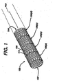
- FIGS 1-3 there is illustrated an exemplary stent 100.
- Figures 1-3 illustrate the stent 100 in its unexpanded or compressed state.
- the stent 100 comprises a superelastic alloy such as Nitinol. More preferably, the stent 100 is formed from an alloy comprising from about 50.5 to 60.0 percent Ni by atomic weight and the remainder Ti. Even more preferably, the stent 100 is formed from an alloy comprising about 55 percent Ni and about 45 percent Ti.
- the stent 100 is preferably designed such that it is superelastic at body temperature, and preferably has an Af temperature in the range from about 24° C to about 37° C. The superelastic design of the stent 100 makes it crush recoverable and thus suitable as a stent or frame for any number of vascular devices for different applications.
- the stent 100 comprises a tubular configuration having front and back open ends 102, 104 and defining a longitudinal axis 103 extending therebetween.
- the stent 100 has a first diameter for insertion into a patient and navigation through the vessels and a second diameter for deployment into the target area of a vessel with the second diameter being greater than the first diameter.
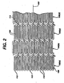
- the stent 100 comprises a plurality of adjacent hoops 106(a)-(d) extending between the front and back ends 102, 104.
- the hoops 106(a)-(d) include a plurality of longitudinally arranged struts 108 and a plurality of loops 110 connecting adjacent struts 108. Adjacent struts 108 are connected at opposite ends so as to form a substantially S or Z shape pattern.
- the plurality of loops 110 have a substantially semi-circular configuration and are substantially symmetric about their centers 112.
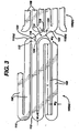
- the stent 100 further comprises a plurality of bridges 114, which connect adjacent hoops 106(a)-(d).
- the details of the bridges 114 are more fully illustrated in Figure 3 .
- Each bridge comprises two ends 116, 118.
- One end of each bridge 114 is attached to one loop 110 on one hoop 106(a) and the other end of each bridge 114 is attached to one loop 110 on an adjacent hoop 106(b).
- the bridges 114 connect adjacent hoops 106(a)-(d) together at bridge to loop connection regions 120,122.
- bridge end 116 is connected to loop 110(a) at bridge to loop connection region 120
- bridge end 118 is connected to loop 110(b) at bridge to loop connection region 122.
- Each bridge to loop connection region includes a center 124.
- the bridge to loop connection regions 120, 122 are separated angularly with respect to the longitudinal axis 103 of the stent 100. In other words, and as illustrated in Figure 3 , a straight line drawn between the center 124 of each bridge to loop connection region 120, 122 on a bridge 114 would not be parallel to the longitudinal axis 103 of the stent 100.
- the above-described geometry better distributes strain throughout the stent 100, prevents metal to metal contact where the stent 100 is bent, and minimizes the opening between the features of the stent 100; namely, struts 108, loops 110 and bridges 114.
- the number of and nature of the design of the struts, loops and bridges are important design factors when determining the working properties and fatigue life properties of the stent. It was previously thought that in order to improve the rigidity of the stent, struts should be large, and thus there should be fewer struts per hoop. However, it is now known that stents having smaller struts and more struts per hoop improve the construction of the stent and provide greater rigidity.
- each hoop has between twenty-four (24) to thirty-six (36) or more struts. It has been determined that a stent having a ratio of number of struts per hoop to strut length which is greater than four hundred has increased rigidity over prior art stents which typically have a ratio of under two hundred.
- the length of a strut (L) is measured in its compressed state parallel to the longitudinal axis 103 of the stent 100 as illustrated in Figure 3 .
- Figure 4 illustrates the stent 100 in its expanded state.
- the geometry of the stent 100 changes quite significantly as it is deployed from its unexpanded state to its expanded state.
- the strut angle and strain levels in the loops and bridges are affected.
- all of the stent features will strain in a predictable manner so that the stent is reliable and uniform in strength.
- the present invention makes use of structural geometries which distribute strain to areas of the strut which are less susceptible to failure than others.
- one of the more vulnerable areas of the stent is the inside radius of the connecting loops.
- the inside radius of the loop would normally be the area with the highest level of strain on the stent. This area is also critical in that it is usually the smallest radius on the stent. Stress concentrations are generally minimized by maintaining the largest radii possible. Similarly, it is preferable to minimize local strain concentrations on the bridge and bridge connection points.
- One way to accomplish this is to utilize the largest possible radii while maintaining feature widths, which are consistent with applied forces. Another consideration is to minimize the maximum open area of the stent. Efficient utilization of the original tube from which the stent is cut, described subsequently, increases the strength of the stent and increases its ability to trap embolic material.
- this design feature allows for maximum utilization of the properties of Nitinol to enhance stent radial strength, improve stent strength uniformity and improve stent fatigue life by minimizing local strain levels.
- this design feature allows for smaller open areas which enhance entrapment of embolic material and improve stent opposition in irregular vessel wall shapes and curves.
- the stent 100 comprises loops 110 each having a width, W1, as measured at its center 112 and parallel to axis 103 (illustrated in Figures 1 and 2 ), which is greater than the width, W2, of each of the struts 108, as measured perpendicular to the axis 103.
- the loops 110 have a variable thickness wherein they are thicker at their centers 64. This configuration increases strain deformation at the strut and reduces the maximum strain levels at the extreme radii of the loop. This reduces the risk of stent failure and allows for maximization of the radial strength properties of the stent. This feature is particularly advantageous for stents having large expansion ratios, which in turn requires them to have extreme bending requirements where large elastic strains are required.
- strut angle and loop strain is affected.
- the bridges connect loops on adjacent hoops, the bridges are affected by the application of a torque anywhere along the length of the stent. If the bridge design is duplicated around the stent perimeter, the displacement causes a rotational shifting of the two loops connected by each bridge. If the bridge design is duplicated throughout the stent, this shift will occur down the length of the stent. This is a cumulative effect as one considers rotation of one end with respect to the other, for example, upon deployment. When a strut is loaded into a delivery system, the stent may be twisted, thereby causing the above-described rotational shifting.
- stent delivery systems deploy the distal end of the stent first and then allow the proximal end to expand. It would be undesirable to allow the distal end of the stent to anchor into the vessel wall while holding the remainder of the stent fixed and then deploying the proximal end of the stent thereby potentially causing the proximal end to rotate as it expands and unwinds. Such rotation may cause damage to the vessel.
- the above-described problem is minimized by mirroring the bridge geometry longitudinally down the stent.
- the rotational shift of the S-shaped sections may be made to alternate which will minimize large rotational changes between any two points on a given stent during deployment or constraint.
- the bridges 114 connecting hoop 106(b) to hoop 106(c) are angled upwardly from left to right, while the bridge 114 connecting hoop 106(c) to hoop 106(d) are angled downwardly from left to right. This alternating pattern is repeated down the length of the stent.
- This alternating pattern of bridge shapes improves the torsional characteristics of the stent so as to minimize any twisting or rotation of the stent with respect to any two hoops.
- This alternating bridge shape is particularly beneficial if the stent starts to twist in vivo. Alternating bridge shapes tend to minimize this effect.
- the diameter of a stent having bridges which are all shaped in the same direction will tend to grow if twisted in one direction and shrink if twisted in the other direction. With alternating bridge shapes, this effect is minimized and localized.
- stents are laser cut from small diameter tubing.
- this manufacturing process leads to designs with features having axial widths which are larger than the tube wall thickness from which the stent is cut.
- the stent is compressed, most of the bending occurs in the plane that is created if one were to cut longitudinally down the stent and flatten it out.
- loops and struts with widths greater than their thicknesses have a greater resistance to this in-plane bending than they do to out-of-plane bending. Given this, the bridges and struts tend to twist so that the stent as a whole can bend more easily.
- the widths of the struts (W2), loops (W1) and bridges (W3) are equal to or less than the wall thickness of the tube from which the stent is cut. Therefore, substantially all bending, and therefore, all strains are out-of-plane. This minimizes twisting of the stent, which minimizes or eliminates buckling and unpredictable strain conditions.
- the stent-based venous valve of the present invention comprises a self-expanding stent in which one or more of its elements are deformed inwardly towards its center, and a biocompatible fabric which is attached to the one or more deformed elements to form one or more valve flaps.
- the one or more valve flaps preferably occlude the lumen of the stent when there is no pressure differential between the upstream and downstream regions of the stent. Essentially, the occlusion of the stent lumen, and thus the vessel in which the stent is positioned, is the neutral position for the one or more valve flaps.
- the one or more valve flaps may be positioned anywhere within the stent, including proximate to one of the open ends of the stent. In the exemplary embodiment illustrated in Figure 5 , the one or more valve flaps 500 are positioned substantially in the center of the stent 100 as measured along the longitudinal axis 103. It is important to note that a multiplicity of different stent designs exist and that the stent-based venous valve may be constructed utilizing any of these stents.
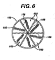
- FIG. 6 there is illustrated an end view of the stent-based venous valve 600 of the present invention.
- Any of the elements comprising the stent 100 are deformed inwardly to form the frame or support structure of the one or more valve flaps.
- the bridges 114, struts 108 and/or loops 110 may be utilized.
- the struts 108 are utilized. In order to deform the struts 108 out of the circumferential plane, the struts 108 have to be severed.
- the length of the deformed strut 108 and thus the point at which it is severed along its length depends on a number of factors, including the diameter of the stent 100, the number of deformed struts 108 comprising the frame of a valve flap and the number of valve flaps. With respect to the diameter factor, the length of the deformed strut 108 may vary with stent 100 diameter in order to provide sufficient support for the one or more valve flaps. For example, as the diameter of the stent 100 increases, the length of the deformed strut 108 should also preferably increase to compensate for the increased surface area of the one or more valve flaps.
- the length of the deformed struts 108 will vary depending on the design and number of the one or more valve flaps.
- the length of the deformed struts 108 should be substantially equal to the radius of the stent 100 so that the apex of each triangularly shaped valve flap meets and is supported in the center of the lumen in order to substantially occlude the lumen in the absence of a pressure differential as described above.
- valve flaps having any number of configurations may be utilized in the stent-based venous valve of the present invention.
- a single valve flap may be formed utilizing one or more deformed struts 108.
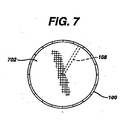
- a single deformed strut 108 may support a substantially circularly shaped section 702 of biocompatible fabric having a diameter substantially equal to the inner diameter of the stent 100.
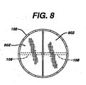
- two valve flaps 802 may be formed utilizing one or more deformed struts 108.
- back to back substantially D-shaped valve flaps may be utilized.
- six substantially triangularly shaped valve flaps 602 are utilized.
- valve flaps 602 cannot have a true triangular shape because the base of each valve flap 602 is curved to fit the circumferential arc of the stent 100.
- Each valve flap 602 comprises two deformed struts 108, which are angled to form the legs of the valve flap 602. Given that there are six valve flaps 602, each comprising two deformed struts 108, a total of twelve deformed struts 108 are utilized.
- Each of the deformed struts 108 extends from the wall of the stent 100 towards the center of the lumen such that their distal ends are proximate one another.
- Each of the deformed struts 108 may extend from the circumferential plane of the stent 100 substantially perpendicular thereto, or at any other angle as long as the distal ends terminate proximate to the center of the lumen. As stated above, the deformed struts 108 should be long enough to provide sufficient support for the valve flaps 602. Accordingly, depending on the angle, the length of each of the deformed struts 108 may vary. If any other angle other than ninety degrees is utilized, the deformed struts will be pointing more towards one of the open ends 102, 104 of the stent 100 than the center of the stent 100.
- the deformed struts 108 and thus the valve flaps 602 extend at an angle in the range from about twenty degrees to about seventy degrees.
- the end of the stent 100 towards which the deformed struts 108 are angled is the downstream end of the stent-based venous valve.
- the valve flaps 602 easily open under the pressure differential existing in the venous position of the circulatory system. Accordingly, the downstream end of the stent-based venous valve 602 should be positioned at the downstream end of the section of the vein where the stent-based venous valve 600 is to be positioned.
- the angling of the valve flaps 602 allows the stent-based venous valve 600 to be compressed for delivery.
- the valve flaps 602 simply deflect further along the longitudinal axis in the direction in which they are angled, thereby reducing the angle of the deformed struts 108.
- the valve flaps 602 return to an angle in the range set forth above.
- struts 108 In order to maintain the strength of the deformed struts 108 comprising the frames of the valve flaps 602 while affording adequate fatigue lifetime, it is preferable to have struts 108 with variable strut width, i.e., zones of reduced stiffness where the strut 108 begins to bend out of the circumferential plane of the stent 100.
- the struts 108 may be deformed at any time during the stent manufacturing process described subsequently, or upon completion of the stent manufacturing process as part of a separate valve manufacturing process.
- Each of the valve flaps 602 comprise the frame formed from the deformed elements 108 as described above, and a biocompatible material attached thereto. Any suitable lightweight, strong, fluid impervious, biocompatible material may be utilized. In a preferred embodiment, a Dacron® or Teflon® fabric may be utilized. The fabric may be attached in any suitable manner and by any suitable means. For example, the fabric may be removably attached or permanently attached to the deformed elements. The fabric may be attached to the elements utilizing sutures, staples, chemical/heat bonding and/or adhesive. In a preferred embodiment, the fabric is attached utilizing sutures.
- anchors may be necessary to include anchors to prevent migration of the stent-based venous valve due to the weight of the blood upstream of the valve flaps 602.
- Such anchors would be incorporated by bending metallic features of the stent 100 outwards from the circumferential plane of the stent 100.
- one or more of the elements comprising the stent 100 may be deformed outwardly from the stent 100 and formed into hooks or barbs which may be made to engage the endoluminal surface of the host vein.
- Stents may be manufactured from a number of different materials and utilizing a number of different processes/techniques.
- the nickel-titanium self-expanding stent utilized in the stent-based venous valve of the present invention is preferably manufactured utilizing the materials and processes as generally described below. Sections of Nitinol tubing are cut into stents by machines in which the tubing is secured into position while a laser cuts predetermined patterns, such as the patterns described above, out of the tubing. Essentially, the machines are adapted to hold the tubing at its open ends while a cutting laser, preferably under microprocessor control, cuts the predetermined pattern.
- the pattern dimensions, geometries and associated laser positioning requirements are preprogrammed into a microprocessor based system, which controls all aspects of the laser cutting process.
- the length and the diameter of the section of tubing depends upon the size of the stent to be manufactured. Although stents are manufactured at a number of fixed dimensions, any size stent may be manufactured utilizing these techniques.
- Nitinol tubing is commercially available from a number of suppliers, including Nitinol Devices and Components, Freemont, California. Also, the cutting machines are commercially available and their use is known in the art.
- the rough stent is treated and polished.
- the rough stent may be polished utilizing any number of processes well known to those skilled in the relevant art, including electropolishing and chemical polishing.
- the rough stents may be polished to the desired smoothness using one or more polishing techniques.
- the polished stent preferably has smooth surfaces with substantially no surface irregularities that might cause damage during or after deployment into a target vessel.
- the polished stent is then cooled until it is completely martensitic, crimped down to its unexpanded diameter and loaded into the sheath of a delivery apparatus, which are known to those of ordinary skill in the relevant art.
- the stents are inspected to ensure that it meets all design requirements and all quality requirements.
- the stents are preferably inspected/tested using a number of criteria, including pattern regularity, smoothness and dimension.
- a particular stent which fails to meet a certain criterion may be reworked one or more times in order to correct the defect, depending on where in the process it failed.
- the number of times a stent may be reworked is limited.
- the nickel-titanium alloy itself may always be re-utilized.
- the above process may be modified and/or further steps may be added.
- the cutting step may be modified such that certain elements are severed and then deformed inwards in a separate step as described above.
- the biocompatible fabric may be attached to the deformed elements upon completion of the polishing step and preferably prior to the crimping step utilizing any of the attachment means/methods described above.
- the attachment of the fabric may be done manually or by an automated means.
- the completed stent-based venous valve may be crimped similarly to a stent and loaded into a stent delivery device.
- the design and operation of stent delivery systems are well known in the art.
- stents in general, as well as other medical devices may exhibit reduced radiopacity under X-ray fluoroscopy.
- markers made from highly radiopaque materials to the stent, or to use radiopaque materials in plating or coating processes.
- Those materials are typically gold, platinum, or tantalum.
- there is a certain challenge to overcome namely, that of galvanic corrosion.
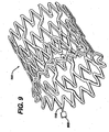
- the cutting pattern of the stent 100 includes at least one tab or marker 900 attached to the loops 110 at the front and back ends of the stent 100.
- These tabs 900 may be formed from any suitable material, and are preferably formed from a highly radiopaque material to assist in positioning the stent-based venous valve within the lumen of the vessel.
- a radiopaque material like gold, platinum, tantalum, niobium, molybdenum, rhodium, palladium, silver, hafnium, tungsten or iridium with the nickel titanium at specific locations and on specific features of the stent, for example tabs 900.
- Means for applying this heat may include devices such as lasers, induction heating, electric arc melting, resistance heating and electron beam melting, and are well known to those of ordinary skill in the art, and are commercially available.
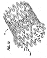
- the sphere 1000 remains attached to the device upon solidification.
- the sphere 1000 includes a micro-alloy of nickel titanium and a radiopaque alloy chosen from a group consisting of gold, platinum, tantalum, niobium, molybdenum, rhodium, palladium, silver, hafnium, tungsten and iridium, while the chemical composition of the balance of the device remains unchanged.
- the resulting nickel titanium alloy has a much reduced tendency to create a galvanic element with the binary nickel titanium.
Abstract
Description
- The present invention relates to medical devices, and more particularly to stent-based venous valves.
- The vertebrate circulatory system comprises three major types of blood vessels; namely, arteries, capillaries and veins. Arteries carry oxygen-rich blood from the heart to the other organs and veins carry oxygen-depleted blood from the organs back to the heart. The pulmonary vein is an exception in that it carries oxygen-rich blood from the lungs to the heart. When an artery enters an organ, it divides into a multiplicity of smaller branches called arterioles. Metarterioles are small vessels that link arterioles to venules, which are the multiplicity of smaller vessels that branch from veins. Capillaries branch off from and are connected to metarterioles. Capillaries also interconnect with one another forming long and intricate capillary networks. After blood supplied by arteries courses through an organ via a capillary network, blood enters the venules which eventually merge into veins and is transported back to the heart.
- Given the nature of the circulatory system, it is easy to understand that blood pressure in arteries is much greater than in veins. To compensate for the much lower blood pressure, veins comprise low flow resistance tissues and venous valves. The primary benefit of venous valves is their ability to limit the backflow of blood traveling through the venous portion of the circulatory system. Numerous venous valves are located throughout the veins, thereby ensuring that the blood travels through the veins and towards the heart.
- The normally low blood pressure in the venous portion of the circulatory system is supplemented by the contraction of skeletal muscles. Essentially, the contraction of the muscles compresses and drives the blood through the veins. The venous valves check the backflow of blood through the veins, thereby ensuring that blood is driven back to the heart. The backflow checking function performed by the venous valves also minimizes the effect of a sudden increase in blood pressure caused, for example, by heavy exertion. In addition, venous valves also evenly distribute blood in the veins by segregating portions of blood flowing through the venous portion of the circulatory system. Any damage to the venous valves disrupts the normal flow of blood.
- Venous valves are particularly important in the lower extremities. The venous system in the lower extremities generally consists of deep veins and superficial veins, which lie just below the skin surface. The deep and superficial veins are interconnected by perforating veins. Blood generally flows upwards through the legs towards the heart and from the superficial to deep veins. The venous valves are situated in the deep, superficial and perforating veins to ensure the normal direction of blood flow.
- Venous valves can become incompetent or damaged by disease, for example, phlebitis, injury or the result of an inherited malformation. Incompetent or damaged venous valves usually leak blood. The backflow of blood passing through leaking venous valves may cause numerous problems. As described above, blood normally flows upwards from the lower extremities, and from the superficial to deep veins. Leaking venous valves allow for blood regurgitation reflux causing blood to improperly flow back down through the veins. Blood can then stagnate in sections of certain veins, and in particular, the veins in the lower extremities. This stagnation of blood raises blood pressure and dilates the veins and venous valves. The dilation of one vein may in turn disrupt the proper functioning of other venous valves in a cascading manner. The dilation of these valves may lead to chronic venous insufficiency. Chronic venous insufficiency is a severe form of venous disease and is a pathological condition of the skin and subcutaneous tissues that results from venous hypertension and prolonged stasis of venous blood due to valvular incompetence both of a primary nature and of a secondary nature following past illnesses of the venous subsystem. Chronic venous insufficiency progresses through various stages of symptom severity which in order of severity include venous flare, edema, hyper-pigmentation i.e. discoloration of the skin, eczema, induration i.e. thickening of the skin, and ulcers. If neglected, chronic valve insufficiency may necessitate amputation of the neglected limb.
- Numerous therapies have been advanced to treat symptoms and to correct incompetent valves. Less invasive procedures include compression, elevation and wound care. Compression involves the use of elastic stockings to compress the affected area. Compression is a conservative therapy and is typically effective in a majority of cases. However, the elastic stockings are uncomfortable and expensive. Continuous elevation is frequently used to treat venous ulcers. Elevation of the affected limb improves venous return, reduces the discomfort of ulcers, and encourages healing. Elevation, however, is contraindicated in patients with cardiopulmonary insufficiency. Wound care involves the use of antibiotics and antiseptics. Topical antibiotics and antiseptics are frequently utilized to treat ulcers. Zinc paste bandages have been a primary dressing for over a century. However, these treatments tend to be somewhat expensive and are not curative. Other procedures involve surgical intervention to repair, reconstruct or replace the incompetent or damaged venous valves.
- Surgical procedures for incompetent or damaged venous valves include valvuloplasty, transplantation, and transposition of veins. Valvuloplasty involves the surgical reconstruction of the valve. Essentially, valvuloplasty is a procedure to surgically modify the venous valves to "tighten" them. Transposition of veins involves surgically bypassing sections of veins possessing the incompetent or damaged valves with veins possessing viable valves. Transplantation involves surgically transplanting one or more of a patient's viable valves for the incompetent or damaged valve. A more detailed discussion of these surgical procedures is given in "Reconstruction of Venous Valves", R. Gottlub and R. Moy, Venous Valves, 1986, Part V, section 3.
- The above-described surgical procedures provide somewhat limited results. The leaflets of venous valves are generally thin, and once the valve becomes incompetent or destroyed, any repair provides only marginal relief. Venous valves may also be damaged when the valve is being reconstructed, transpositioned, or transplanted. The endothelium tissue layer of the vein may also be damaged during handling. This reduces the viability of the vein graft after implant. Another disadvantage with transplantation procedures is the need to use the patient's own vein segment in order to avoid the complications posed by rejection. In addition, the use of a patient's own vein segment predisposes that the incompetence or damage did not arise from inherited factors or diseases which will affect the transplanted valve.
- Another surgical procedure involves the removal of the valve. In this procedure, the incompetent or damaged valve is completely removed. While this procedure removes any potential impediment to normal blood flow, it does not solve the backflow problem.
- As an alternative to surgical intervention, drug therapy to correct venous valvular incompetence has been utilized. Currently, however, there are no effective drug therapies available.
- Other means and methods for treating and/or correcting damaged or incompetent valves include utilizing xenograft valve transplantation (monocusp bovine pericardium), prosthetic/bioprosthetic heart valves and vascular grafts, and artificial venous valves. The use of xenograft valve transplantation is still in the experimental stages. In addition, after a given amount of time, it has been found that luminal deposits of fibrous material develops. Prosthetic heart valves are usually made from porcine valves and porcine heart valves have a geometry unsuitable as a replacement for venous valves. These types of valves are also generally larger than venous valves, and include valve leaflets generally thicker and stiffer than the leaflets of venous valves. The thicker heart valve leaflets require a greater opening pressure. The greater required opening pressure makes such valves unsuitable for the venous system. Artificial venous valves are known in the art. For example,
U.S. Patent No. 5,358,518 to Camilli discloses an artificial venous valve. The device comprises a hollow elongated support and a plate mounted therein. The plate is moveably mounted such that when in a first position, blood flows through the valve and when in a second position, blood cannot flow through the valve. A pressure differential drives the plate. Although the device is made from biocompatible materials, the use of non-physiological materials in this type of pivoting plate arrangement increases the risk of hemolysis and/or thrombosis. -
US-5855597 discusses a star-shaped stent and replacement valve for use in repairing a damaged cardiac valve. Two to eight star-shaped members are interconnected in a chain. A replacement aortic valve is received in the central opening through all of the star shaped members. The valve is formed from a biocompatible material and is sewn to inwardly-directed points of the star-shaped members. -
WO-A-01/49213 - The stent-based venous valve of the present invention provides a means for overcoming the difficulties associated with the treatments and devices as briefly described above.
- In accordance with one aspect, the present invention is directed to an artificial venous valve as defined in appended claim 1. The artificial venous valve comprises a stent formed from a lattice of interconnected elements and having a substantially cylindrical configuration with first and second open ends. One or more of the elements are deformed inwardly out of the circumferential plane. The artificial venous valve also comprises a biocompatible material attached to the one or more elements thereby forming one or more valve flaps.
- The stent may have a compressed diameter for insertion into a vessel and an expanded diameter for deployment into the vessel. The one or more of the elements are deformed out of the circumferential plane at a first angle when the self-expanding stent is at its compressed diameter and at a second angle when the self-expanding stent is at its expanded diameter. The second angle is greater than the first angle. The artificial venous valve also comprises a biocompatible material attached to the one or more elements thereby forming one or more valve flaps.
- The stent-based venous valve of the present invention utilizes a modified stent to create an effective artificial venous valve. The stent may be a self-expanding stent. One or more elements comprising the framework of the self-expanding stent are deformed out of the circumferential plane and towards the center of the stent and a lightweight, biocompatible fabric is attached thereto. The attachment of the fabric to the elements creates flaps which function to regulate the flow of blood in the veins into which it is positioned. The slightly higher blood pressure upstream of the stent easily opens the flaps and allows the blood to flow through. In the absence of a pressure differential, the flaps return to their normally closed position, thereby substantially preventing the backflow of blood.
- The stent-based venous valve of the present invention may be percutaneously delivered to the venous sub-system by releasing it from a catheter to assist or replace deteriorating natural venous valves by allowing flow towards the heart and preventing backflow. Since the venous valve is percutaneously delivered, the whole procedure is minimally invasive. The stent-based venous valve creates very little resistance in the vessel and offers minimal complication risks. In addition, since the stent-based venous valve utilizes modified existing technology, physicians will be more comfortable performing the valve replacement procedure.
- The stent-based venous valve of the present invention may be more cost effectively manufactured by utilizing existing manufacturing techniques that are currently used for the manufacture of stents with only slight modification. Accordingly, high quality, reliable venous valves may be easily manufactured at relatively low cost.
- The foregoing and other features and advantages of the invention will be apparent from the following, more particular description of preferred embodiments of the invention, as illustrated in the accompanying drawings.
-
Figure 1 is a perspective view of a stent in a compressed state useful for understanding the present invention. -
Figure 2 is a sectional, flat view of the stent illustrated inFigure 1 . -
Figure 3 is an enlarged view of the section of the stent illustrated inFigure 2 . -
Figure 4 is a perspective view of the stent illustrated inFigure 1 in its expanded state. -
Figure 5 is a perspective view of the stent-based venous valve in accordance with the present invention. -
Figure 6 is an end view of the stent-based venous valve in accordance with the present invention. -
Figure 7 is an end view of the stent-based venous valve having a single valve flap in accordance with the present invention. -
Figure 8 is an end view of the stent-based venous valve having two valve flaps in accordance with the present invention. -
Figure 9 is an enlarged perspective view of the end of the stent-based venous valve having a tab in accordance with the present invention. -
Figure 10 is an enlarged perspective end view of the stent-based venous valve having a radiopaque marker in accordance with the present invention. - The stent-based venous valve of the present invention comprises a self-expanding stent in which one or more of its elements are deformed inwardly towards its center, and a biocompatible fabric which is attached to the one or more deformed elements. With no pressure differential between the upstream and downstream ends of the venous valve, the fabric covered elements substantially occlude the lumen. When there is a pressure differential, albeit slight, due to the pumping of the heart, the fabric covered elements open easily and allow blood to flow therethrough with substantially no backflow. Given the design of the circulatory system, the pressure in the upstream portion of the venous system should always be higher than the pressure downstream. The venous valve is percutaneously delivered to the venous system by releasing it from a delivery catheter and functions to assist or replace incompetent or damaged natural venous valves by allowing normal blood flow and preventing or reducing backflow.
- Referring to
Figures 1-3 , there is illustrated anexemplary stent 100.Figures 1-3 illustrate thestent 100 in its unexpanded or compressed state. In a preferred embodiment, thestent 100 comprises a superelastic alloy such as Nitinol. More preferably, thestent 100 is formed from an alloy comprising from about 50.5 to 60.0 percent Ni by atomic weight and the remainder Ti. Even more preferably, thestent 100 is formed from an alloy comprising about 55 percent Ni and about 45 percent Ti. Thestent 100 is preferably designed such that it is superelastic at body temperature, and preferably has an Af temperature in the range from about 24° C to about 37° C. The superelastic design of thestent 100 makes it crush recoverable and thus suitable as a stent or frame for any number of vascular devices for different applications. - The
stent 100 comprises a tubular configuration having front and back open ends 102, 104 and defining alongitudinal axis 103 extending therebetween. Thestent 100 has a first diameter for insertion into a patient and navigation through the vessels and a second diameter for deployment into the target area of a vessel with the second diameter being greater than the first diameter. Thestent 100 comprises a plurality of adjacent hoops 106(a)-(d) extending between the front and back ends 102, 104. The hoops 106(a)-(d) include a plurality of longitudinally arrangedstruts 108 and a plurality ofloops 110 connectingadjacent struts 108.Adjacent struts 108 are connected at opposite ends so as to form a substantially S or Z shape pattern. The plurality ofloops 110 have a substantially semi-circular configuration and are substantially symmetric about theircenters 112. - The
stent 100 further comprises a plurality ofbridges 114, which connect adjacent hoops 106(a)-(d). The details of thebridges 114 are more fully illustrated inFigure 3 . Each bridge comprises two ends 116, 118. One end of eachbridge 114 is attached to oneloop 110 on one hoop 106(a) and the other end of eachbridge 114 is attached to oneloop 110 on an adjacent hoop 106(b). Thebridges 114 connect adjacent hoops 106(a)-(d) together at bridge to loop connection regions 120,122. For example,bridge end 116 is connected to loop 110(a) at bridge toloop connection region 120, andbridge end 118 is connected to loop 110(b) at bridge toloop connection region 122. Each bridge to loop connection region includes acenter 124. The bridge toloop connection regions longitudinal axis 103 of thestent 100. In other words, and as illustrated inFigure 3 , a straight line drawn between thecenter 124 of each bridge toloop connection region bridge 114 would not be parallel to thelongitudinal axis 103 of thestent 100. - The above-described geometry better distributes strain throughout the
stent 100, prevents metal to metal contact where thestent 100 is bent, and minimizes the opening between the features of thestent 100; namely, struts 108,loops 110 and bridges 114. The number of and nature of the design of the struts, loops and bridges are important design factors when determining the working properties and fatigue life properties of the stent. It was previously thought that in order to improve the rigidity of the stent, struts should be large, and thus there should be fewer struts per hoop. However, it is now known that stents having smaller struts and more struts per hoop improve the construction of the stent and provide greater rigidity. Preferably, each hoop has between twenty-four (24) to thirty-six (36) or more struts. It has been determined that a stent having a ratio of number of struts per hoop to strut length which is greater than four hundred has increased rigidity over prior art stents which typically have a ratio of under two hundred. The length of a strut (L) is measured in its compressed state parallel to thelongitudinal axis 103 of thestent 100 as illustrated inFigure 3 . -
Figure 4 illustrates thestent 100 in its expanded state. As may be seen from a comparison between thestent 100 illustrated inFigures 1-3 and thestent 100 illustrated inFigure 4 , the geometry of thestent 100 changes quite significantly as it is deployed from its unexpanded state to its expanded state. As a stent undergoes diametric change, the strut angle and strain levels in the loops and bridges are affected. Preferably, all of the stent features will strain in a predictable manner so that the stent is reliable and uniform in strength. In addition, it is preferable to minimize the maximum strain experienced by the struts, loops and bridges since Nitinol properties are more generally limited by strain rather than by stress. - In trying to minimize the maximum strain experienced by the features of the stent, the present invention makes use of structural geometries which distribute strain to areas of the strut which are less susceptible to failure than others. For example, one of the more vulnerable areas of the stent is the inside radius of the connecting loops. In going from its unexpanded state to its expanded state the connecting loops of the stent undergo the most deformation of all the stent features. The inside radius of the loop would normally be the area with the highest level of strain on the stent. This area is also critical in that it is usually the smallest radius on the stent. Stress concentrations are generally minimized by maintaining the largest radii possible. Similarly, it is preferable to minimize local strain concentrations on the bridge and bridge connection points. One way to accomplish this is to utilize the largest possible radii while maintaining feature widths, which are consistent with applied forces. Another consideration is to minimize the maximum open area of the stent. Efficient utilization of the original tube from which the stent is cut, described subsequently, increases the strength of the stent and increases its ability to trap embolic material.
- Many of these design objectives are accomplished in a preferred embodiment of the stent of the present invention as illustrated in
Figures 1-3 . As seen from these figures, the most compact designs, which maintain the largest radii at the loop to bridge connections, are non-symmetric with respect to the centerline of the loop. That is, loop to bridge connection region centers 124 are off set from thecenter 112 of theloops 110 to which they are attached. This feature is particularly advantageous for stents having large expansion ratios, which in turn requires them to have extreme bending requirements where large elastic strains are required. Nitinol can withstand extremely high elastic strain deformation, so the above features are well suited to stents made from this alloy. Therefore, this design feature allows for maximum utilization of the properties of Nitinol to enhance stent radial strength, improve stent strength uniformity and improve stent fatigue life by minimizing local strain levels. In addition, this design feature allows for smaller open areas which enhance entrapment of embolic material and improve stent opposition in irregular vessel wall shapes and curves. - As illustrated in
Figure 3 , thestent 100 comprisesloops 110 each having a width, W1, as measured at itscenter 112 and parallel to axis 103 (illustrated inFigures 1 and2 ), which is greater than the width, W2, of each of thestruts 108, as measured perpendicular to theaxis 103. In a preferred embodiment, theloops 110 have a variable thickness wherein they are thicker at their centers 64. This configuration increases strain deformation at the strut and reduces the maximum strain levels at the extreme radii of the loop. This reduces the risk of stent failure and allows for maximization of the radial strength properties of the stent. This feature is particularly advantageous for stents having large expansion ratios, which in turn requires them to have extreme bending requirements where large elastic strains are required. - As mentioned above, as a stent undergoes diametric change, strut angle and loop strain is affected. Given that the bridges connect loops on adjacent hoops, the bridges are affected by the application of a torque anywhere along the length of the stent. If the bridge design is duplicated around the stent perimeter, the displacement causes a rotational shifting of the two loops connected by each bridge. If the bridge design is duplicated throughout the stent, this shift will occur down the length of the stent. This is a cumulative effect as one considers rotation of one end with respect to the other, for example, upon deployment. When a strut is loaded into a delivery system, the stent may be twisted, thereby causing the above-described rotational shifting. Typically, stent delivery systems deploy the distal end of the stent first and then allow the proximal end to expand. It would be undesirable to allow the distal end of the stent to anchor into the vessel wall while holding the remainder of the stent fixed and then deploying the proximal end of the stent thereby potentially causing the proximal end to rotate as it expands and unwinds. Such rotation may cause damage to the vessel.
- In the exemplary embodiment described herein, the above-described problem is minimized by mirroring the bridge geometry longitudinally down the stent. Essentially, by mirroring the bridge geometry longitudinally along the stent, the rotational shift of the S-shaped sections may be made to alternate which will minimize large rotational changes between any two points on a given stent during deployment or constraint. As illustrated in
Figure 2 , thebridges 114 connecting hoop 106(b) to hoop 106(c) are angled upwardly from left to right, while thebridge 114 connecting hoop 106(c) to hoop 106(d) are angled downwardly from left to right. This alternating pattern is repeated down the length of the stent. This alternating pattern of bridge shapes improves the torsional characteristics of the stent so as to minimize any twisting or rotation of the stent with respect to any two hoops. This alternating bridge shape is particularly beneficial if the stent starts to twist in vivo. Alternating bridge shapes tend to minimize this effect. The diameter of a stent having bridges which are all shaped in the same direction will tend to grow if twisted in one direction and shrink if twisted in the other direction. With alternating bridge shapes, this effect is minimized and localized. - Preferably, stents are laser cut from small diameter tubing. For prior art stents, this manufacturing process leads to designs with features having axial widths which are larger than the tube wall thickness from which the stent is cut. When the stent is compressed, most of the bending occurs in the plane that is created if one were to cut longitudinally down the stent and flatten it out. However, for the individual bridges, loops and struts with widths greater than their thicknesses have a greater resistance to this in-plane bending than they do to out-of-plane bending. Given this, the bridges and struts tend to twist so that the stent as a whole can bend more easily. This twisting is essentially a buckling which is unpredictable and can cause potentially high strain. However, in a preferred embodiment of the present invention as illustrated in
Figure 3 , the widths of the struts (W2), loops (W1) and bridges (W3) are equal to or less than the wall thickness of the tube from which the stent is cut. Therefore, substantially all bending, and therefore, all strains are out-of-plane. This minimizes twisting of the stent, which minimizes or eliminates buckling and unpredictable strain conditions. - As briefly described above, the stent-based venous valve of the present invention comprises a self-expanding stent in which one or more of its elements are deformed inwardly towards its center, and a biocompatible fabric which is attached to the one or more deformed elements to form one or more valve flaps. In order to prevent the backflow of blood, the one or more valve flaps preferably occlude the lumen of the stent when there is no pressure differential between the upstream and downstream regions of the stent. Essentially, the occlusion of the stent lumen, and thus the vessel in which the stent is positioned, is the neutral position for the one or more valve flaps. Under normal circumstances, the pressure upstream is greater than the pressure downstream due to the nature of the circulatory system, as briefly described above. This pressure differential, albeit slight, easily opens the one or more valve flaps and allows the blood to flow substantially unimpeded. The one or more valve flaps may be positioned anywhere within the stent, including proximate to one of the open ends of the stent. In the exemplary embodiment illustrated in
Figure 5 , the one or more valve flaps 500 are positioned substantially in the center of thestent 100 as measured along thelongitudinal axis 103. It is important to note that a multiplicity of different stent designs exist and that the stent-based venous valve may be constructed utilizing any of these stents. - Referring to
Figure 6 , there is illustrated an end view of the stent-basedvenous valve 600 of the present invention. Any of the elements comprising thestent 100 are deformed inwardly to form the frame or support structure of the one or more valve flaps. For example, thebridges 114, struts 108 and/orloops 110 may be utilized. In the exemplary embodiment illustrated inFigure 6 , thestruts 108 are utilized. In order to deform thestruts 108 out of the circumferential plane, thestruts 108 have to be severed. The length of thedeformed strut 108 and thus the point at which it is severed along its length depends on a number of factors, including the diameter of thestent 100, the number ofdeformed struts 108 comprising the frame of a valve flap and the number of valve flaps. With respect to the diameter factor, the length of thedeformed strut 108 may vary withstent 100 diameter in order to provide sufficient support for the one or more valve flaps. For example, as the diameter of thestent 100 increases, the length of thedeformed strut 108 should also preferably increase to compensate for the increased surface area of the one or more valve flaps. With respect to the number ofdeformed struts 108 comprising each frame of the one or more valve flaps and the number of valve flaps, it is obvious that the length of thedeformed struts 108 will vary depending on the design and number of the one or more valve flaps. For example, if triangularly shaped valve flaps are utilized, twodeformed struts 108 may be utilized as the legs of the triangularly shaped valve flap, and the length of thedeformed struts 108 should be substantially equal to the radius of thestent 100 so that the apex of each triangularly shaped valve flap meets and is supported in the center of the lumen in order to substantially occlude the lumen in the absence of a pressure differential as described above. - Any number of valve flaps having any number of configurations may be utilized in the stent-based venous valve of the present invention. In one exemplary embodiment, a single valve flap may be formed utilizing one or more
deformed struts 108. For example, as illustrated inFigure 7 , a singledeformed strut 108 may support a substantially circularly shapedsection 702 of biocompatible fabric having a diameter substantially equal to the inner diameter of thestent 100. In another exemplary embodiment, as illustrated inFigure 8 , twovalve flaps 802 may be formed utilizing one or moredeformed struts 108. For example, back to back substantially D-shaped valve flaps may be utilized. In the exemplary embodiment illustrated inFigure 6 , six substantially triangularly shaped valve flaps 602 are utilized. The valve flaps 602 cannot have a true triangular shape because the base of eachvalve flap 602 is curved to fit the circumferential arc of thestent 100. Eachvalve flap 602 comprises twodeformed struts 108, which are angled to form the legs of thevalve flap 602. Given that there are sixvalve flaps 602, each comprising twodeformed struts 108, a total of twelvedeformed struts 108 are utilized. Each of thedeformed struts 108 extends from the wall of thestent 100 towards the center of the lumen such that their distal ends are proximate one another. Each of thedeformed struts 108 may extend from the circumferential plane of thestent 100 substantially perpendicular thereto, or at any other angle as long as the distal ends terminate proximate to the center of the lumen. As stated above, thedeformed struts 108 should be long enough to provide sufficient support for the valve flaps 602. Accordingly, depending on the angle, the length of each of thedeformed struts 108 may vary. If any other angle other than ninety degrees is utilized, the deformed struts will be pointing more towards one of the open ends 102, 104 of thestent 100 than the center of thestent 100. In a preferred embodiment, thedeformed struts 108 and thus the valve flaps 602, extend at an angle in the range from about twenty degrees to about seventy degrees. The end of thestent 100 towards which thedeformed struts 108 are angled is the downstream end of the stent-based venous valve. With the angle of thedeformed struts 108 in the above range, the valve flaps 602 easily open under the pressure differential existing in the venous position of the circulatory system. Accordingly, the downstream end of the stent-basedvenous valve 602 should be positioned at the downstream end of the section of the vein where the stent-basedvenous valve 600 is to be positioned. - In addition to the above described advantage of angling the valve flaps 602, the angling of the valve flaps 602 allows the stent-based
venous valve 600 to be compressed for delivery. When the stent-basedvenous valve 600 is collapsed for insertion into the vein of a patient, the valve flaps 602 simply deflect further along the longitudinal axis in the direction in which they are angled, thereby reducing the angle of thedeformed struts 108. When the stent-basedvenous valve 600 is expanded during deployment, the valve flaps 602 return to an angle in the range set forth above. - In order to maintain the strength of the
deformed struts 108 comprising the frames of the valve flaps 602 while affording adequate fatigue lifetime, it is preferable to havestruts 108 with variable strut width, i.e., zones of reduced stiffness where thestrut 108 begins to bend out of the circumferential plane of thestent 100. Thestruts 108 may be deformed at any time during the stent manufacturing process described subsequently, or upon completion of the stent manufacturing process as part of a separate valve manufacturing process. - Each of the valve flaps 602 comprise the frame formed from the
deformed elements 108 as described above, and a biocompatible material attached thereto. Any suitable lightweight, strong, fluid impervious, biocompatible material may be utilized. In a preferred embodiment, a Dacron® or Teflon® fabric may be utilized. The fabric may be attached in any suitable manner and by any suitable means. For example, the fabric may be removably attached or permanently attached to the deformed elements. The fabric may be attached to the elements utilizing sutures, staples, chemical/heat bonding and/or adhesive. In a preferred embodiment, the fabric is attached utilizing sutures. - It may be necessary to include anchors to prevent migration of the stent-based venous valve due to the weight of the blood upstream of the valve flaps 602. Such anchors would be incorporated by bending metallic features of the
stent 100 outwards from the circumferential plane of thestent 100. In other words, one or more of the elements comprising thestent 100 may be deformed outwardly from thestent 100 and formed into hooks or barbs which may be made to engage the endoluminal surface of the host vein. - Stents may be manufactured from a number of different materials and utilizing a number of different processes/techniques. The nickel-titanium self-expanding stent utilized in the stent-based venous valve of the present invention is preferably manufactured utilizing the materials and processes as generally described below. Sections of Nitinol tubing are cut into stents by machines in which the tubing is secured into position while a laser cuts predetermined patterns, such as the patterns described above, out of the tubing. Essentially, the machines are adapted to hold the tubing at its open ends while a cutting laser, preferably under microprocessor control, cuts the predetermined pattern. The pattern dimensions, geometries and associated laser positioning requirements are preprogrammed into a microprocessor based system, which controls all aspects of the laser cutting process. The length and the diameter of the section of tubing depends upon the size of the stent to be manufactured. Although stents are manufactured at a number of fixed dimensions, any size stent may be manufactured utilizing these techniques. Nitinol tubing is commercially available from a number of suppliers, including Nitinol Devices and Components, Freemont, California. Also, the cutting machines are commercially available and their use is known in the art.
- Upon completion of the stent cutting step, the rough stent is treated and polished. The rough stent may be polished utilizing any number of processes well known to those skilled in the relevant art, including electropolishing and chemical polishing. The rough stents may be polished to the desired smoothness using one or more polishing techniques. The polished stent preferably has smooth surfaces with substantially no surface irregularities that might cause damage during or after deployment into a target vessel. The polished stent is then cooled until it is completely martensitic, crimped down to its unexpanded diameter and loaded into the sheath of a delivery apparatus, which are known to those of ordinary skill in the relevant art.
- At various stages in the above-described manufacturing process, the stents are inspected to ensure that it meets all design requirements and all quality requirements. For example, the stents are preferably inspected/tested using a number of criteria, including pattern regularity, smoothness and dimension. A particular stent which fails to meet a certain criterion may be reworked one or more times in order to correct the defect, depending on where in the process it failed. The number of times a stent may be reworked is limited. However, the nickel-titanium alloy itself may always be re-utilized.
- In order to manufacture the stent-based venous valve of the present invention, the above process may be modified and/or further steps may be added. For example, the cutting step may be modified such that certain elements are severed and then deformed inwards in a separate step as described above. The biocompatible fabric may be attached to the deformed elements upon completion of the polishing step and preferably prior to the crimping step utilizing any of the attachment means/methods described above. The attachment of the fabric may be done manually or by an automated means. The completed stent-based venous valve may be crimped similarly to a stent and loaded into a stent delivery device. The design and operation of stent delivery systems are well known in the art.
- A concern with stents in general, as well as other medical devices, is that they may exhibit reduced radiopacity under X-ray fluoroscopy. To overcome this problem, it is common practice to attach markers made from highly radiopaque materials to the stent, or to use radiopaque materials in plating or coating processes. Those materials are typically gold, platinum, or tantalum. However, due to the relative position of these materials in the galvanic series versus the position of the base metal of the stent in the galvanic series, there is a certain challenge to overcome; namely, that of galvanic corrosion.
- Referring to
Figure 9 , there is illustrated another exemplary embodiment of the present invention. In this exemplary embodiment, the cutting pattern of thestent 100 includes at least one tab ormarker 900 attached to theloops 110 at the front and back ends of thestent 100. Thesetabs 900 may be formed from any suitable material, and are preferably formed from a highly radiopaque material to assist in positioning the stent-based venous valve within the lumen of the vessel. In this exemplary embodiment, it is preferable to "micro-alloy" a radiopaque material like gold, platinum, tantalum, niobium, molybdenum, rhodium, palladium, silver, hafnium, tungsten or iridium with the nickel titanium at specific locations and on specific features of the stent, forexample tabs 900. Once the predetermined pattern is cut into the tubular member, as described above, in a secondary process, performed in a protective atmosphere or under vacuum, thetabs 900 or other features may selectively be melted by the application of heat from a source, while a predetermined amount of the radiopaque material is added. Means for applying this heat may include devices such as lasers, induction heating, electric arc melting, resistance heating and electron beam melting, and are well known to those of ordinary skill in the art, and are commercially available. Through surface tension, the molten pool will form asphere 1000, as illustrated inFigure 10 . Thesphere 1000 remains attached to the device upon solidification. Thesphere 1000 includes a micro-alloy of nickel titanium and a radiopaque alloy chosen from a group consisting of gold, platinum, tantalum, niobium, molybdenum, rhodium, palladium, silver, hafnium, tungsten and iridium, while the chemical composition of the balance of the device remains unchanged. The resulting nickel titanium alloy has a much reduced tendency to create a galvanic element with the binary nickel titanium. - Although shown and described is what is believed to be the most practical and preferred embodiments, it is apparent that departures from specific designs and methods described and shown will suggest themselves to those skilled in the art and may be used without departing from the spirit and scope of the invention which is defined by the appended claims.
Claims (12)
- An artificial venous valve comprising:a stent (100) formed from a lattice of interconnected elements and having a substantially cylindrical configuration with first and second open ends (102, 104), wherein one or more of the elements are deformed inwardly out of the circumferential plane to form a frame for one or more valve flaps, wherein the stent (100) comprises;a plurality of hoops (106) formed from a plurality of struts (108) connected by a plurality of loops (110); anda plurality of bridges (114) connecting adjacent hoops (106); anda biocompatible material attached to the one or more elements thereby forming one or more valve flaps (500, 602, 702, 802).
- An artificial venous valve according to claim 1, wherein:the stent (100) is a self-expanding stent having a compressed diameter for insertion into a vessel and an expanded diameter for deployment into the vessel, wherein the one or more of the elements are deformed out of the circumferential plane at a first angle when the self-expanding stent is at its compressed diameter and at a second angle when the self-expanding stent is at its expanded diameter, the second angle being greater than the first angle; andwherein the biocompatible material is a biocompatible fabric.
- The artificial venous valve according to claim 1 or 2, wherein the stent comprises a superelastic alloy.
- The artificial venous valve according to claim 3, wherein the alloy comprises from about 50.5 percent to about 60 percent nickel and the remainder comprising titanium.
- The artificial venous valve according to claim 1 or 2, wherein the one or more valve flaps (500, 602, 702, 802) each comprise two deformed elements arranged to form a substantially triangularly shaped support frame.
- The artificial venous valve according to claim 5 when appendent to claim 1, wherein the deformed elements are angled towards one of the first and second open ends (102, 104) at an angle in the range from about twenty degrees to about seventy degrees.
- The artificial venous valve according to claim 3 when appendent to claim 2, wherein the second angle is in the range from about twenty degrees to about seventy degrees.
- The artificial venous valve according to claim 6 or 7, wherein the deformed elements are thinner where they are deformed out of the circumferential plane.
- The artificial venous valve according to claim 1 or 2, wherein the one or more valve flaps (500, 602, 702, 802) are dimensioned to substantially occlude the stent (100) when there are no differential forces acting on the valve flaps (500, 602, 702, 802).
- The artificial venous valve according to claim 9, comprising six valve flaps (500, 600).
- The artificial venous valve according to claim 1, wherein the biocompatible material comprises Teflon®.
- The artificial venous valve according to claim 1, wherein the biocompatible material comprises Dacron®.
Applications Claiming Priority (3)
| Application Number | Priority Date | Filing Date | Title |
|---|---|---|---|
| US813586 | 1985-12-26 | ||
| US09/813,586 US6503272B2 (en) | 2001-03-21 | 2001-03-21 | Stent-based venous valves |
| PCT/US2002/008610 WO2002076349A1 (en) | 2001-03-21 | 2002-03-20 | Stent-based venous valves |
Publications (2)
| Publication Number | Publication Date |
|---|---|
| EP1370201A1 EP1370201A1 (en) | 2003-12-17 |
| EP1370201B1 true EP1370201B1 (en) | 2009-09-02 |
Family
ID=25212826
Family Applications (1)
| Application Number | Title | Priority Date | Filing Date |
|---|---|---|---|
| EP02717683A Expired - Lifetime EP1370201B1 (en) | 2001-03-21 | 2002-03-20 | Stent-based venous valves |
Country Status (9)
| Country | Link |
|---|---|
| US (1) | US6503272B2 (en) |
| EP (1) | EP1370201B1 (en) |
| JP (1) | JP4381681B2 (en) |
| AT (1) | ATE441384T1 (en) |
| AU (1) | AU2002248669B2 (en) |
| CA (1) | CA2441999C (en) |
| DE (1) | DE60233556D1 (en) |
| MX (1) | MXPA03008569A (en) |
| WO (1) | WO2002076349A1 (en) |
Cited By (25)
| Publication number | Priority date | Publication date | Assignee | Title |
|---|---|---|---|---|
| US7857845B2 (en) | 2005-02-10 | 2010-12-28 | Sorin Biomedica Cardio S.R.L. | Cardiac-valve prosthesis |
| US8109996B2 (en) | 2004-03-03 | 2012-02-07 | Sorin Biomedica Cardio, S.R.L. | Minimally-invasive cardiac-valve prosthesis |
| US8512397B2 (en) | 2009-04-27 | 2013-08-20 | Sorin Group Italia S.R.L. | Prosthetic vascular conduit |
| US8685084B2 (en) | 2011-12-29 | 2014-04-01 | Sorin Group Italia S.R.L. | Prosthetic vascular conduit and assembly method |
| US8808369B2 (en) | 2009-10-05 | 2014-08-19 | Mayo Foundation For Medical Education And Research | Minimally invasive aortic valve replacement |
| US8834563B2 (en) | 2008-12-23 | 2014-09-16 | Sorin Group Italia S.R.L. | Expandable prosthetic valve having anchoring appendages |
| US8840661B2 (en) | 2008-05-16 | 2014-09-23 | Sorin Group Italia S.R.L. | Atraumatic prosthetic heart valve prosthesis |
| US9161836B2 (en) | 2011-02-14 | 2015-10-20 | Sorin Group Italia S.R.L. | Sutureless anchoring device for cardiac valve prostheses |
| US9248017B2 (en) | 2010-05-21 | 2016-02-02 | Sorin Group Italia S.R.L. | Support device for valve prostheses and corresponding kit |
| US9289289B2 (en) | 2011-02-14 | 2016-03-22 | Sorin Group Italia S.R.L. | Sutureless anchoring device for cardiac valve prostheses |
| US9848981B2 (en) | 2007-10-12 | 2017-12-26 | Mayo Foundation For Medical Education And Research | Expandable valve prosthesis with sealing mechanism |
| US10856984B2 (en) | 2017-08-25 | 2020-12-08 | Neovasc Tiara Inc. | Sequentially deployed transcatheter mitral valve prosthesis |
| US10940001B2 (en) | 2012-05-30 | 2021-03-09 | Neovasc Tiara Inc. | Methods and apparatus for loading a prosthesis onto a delivery system |
| US11311376B2 (en) | 2019-06-20 | 2022-04-26 | Neovase Tiara Inc. | Low profile prosthetic mitral valve |
| US11357622B2 (en) | 2016-01-29 | 2022-06-14 | Neovase Tiara Inc. | Prosthetic valve for avoiding obstruction of outflow |
| US11389291B2 (en) | 2013-04-04 | 2022-07-19 | Neovase Tiara Inc. | Methods and apparatus for delivering a prosthetic valve to a beating heart |
| US11413139B2 (en) | 2011-11-23 | 2022-08-16 | Neovasc Tiara Inc. | Sequentially deployed transcatheter mitral valve prosthesis |
| US11419720B2 (en) | 2010-05-05 | 2022-08-23 | Neovasc Tiara Inc. | Transcatheter mitral valve prosthesis |
| US11464631B2 (en) | 2016-11-21 | 2022-10-11 | Neovasc Tiara Inc. | Methods and systems for rapid retraction of a transcatheter heart valve delivery system |
| US11491006B2 (en) | 2019-04-10 | 2022-11-08 | Neovasc Tiara Inc. | Prosthetic valve with natural blood flow |
| US11497602B2 (en) | 2012-02-14 | 2022-11-15 | Neovasc Tiara Inc. | Methods and apparatus for engaging a valve prosthesis with tissue |
| US11504231B2 (en) | 2018-05-23 | 2022-11-22 | Corcym S.R.L. | Cardiac valve prosthesis |
| US11602429B2 (en) | 2019-04-01 | 2023-03-14 | Neovasc Tiara Inc. | Controllably deployable prosthetic valve |
| US11737872B2 (en) | 2018-11-08 | 2023-08-29 | Neovasc Tiara Inc. | Ventricular deployment of a transcatheter mitral valve prosthesis |
| US11779742B2 (en) | 2019-05-20 | 2023-10-10 | Neovasc Tiara Inc. | Introducer with hemostasis mechanism |
Families Citing this family (480)
| Publication number | Priority date | Publication date | Assignee | Title |
|---|---|---|---|---|
| US6006134A (en) * | 1998-04-30 | 1999-12-21 | Medtronic, Inc. | Method and device for electronically controlling the beating of a heart using venous electrical stimulation of nerve fibers |
| US5954766A (en) * | 1997-09-16 | 1999-09-21 | Zadno-Azizi; Gholam-Reza | Body fluid flow control device |
| US6503271B2 (en) | 1998-01-09 | 2003-01-07 | Cordis Corporation | Intravascular device with improved radiopacity |
| US7452371B2 (en) * | 1999-06-02 | 2008-11-18 | Cook Incorporated | Implantable vascular device |
| US20020019660A1 (en) * | 1998-09-05 | 2002-02-14 | Marc Gianotti | Methods and apparatus for a curved stent |
| US6682554B2 (en) * | 1998-09-05 | 2004-01-27 | Jomed Gmbh | Methods and apparatus for a stent having an expandable web structure |
| US7887578B2 (en) * | 1998-09-05 | 2011-02-15 | Abbott Laboratories Vascular Enterprises Limited | Stent having an expandable web structure |
| US7815763B2 (en) * | 2001-09-28 | 2010-10-19 | Abbott Laboratories Vascular Enterprises Limited | Porous membranes for medical implants and methods of manufacture |
| US6755856B2 (en) | 1998-09-05 | 2004-06-29 | Abbott Laboratories Vascular Enterprises Limited | Methods and apparatus for stenting comprising enhanced embolic protection, coupled with improved protection against restenosis and thrombus formation |
| US6254564B1 (en) | 1998-09-10 | 2001-07-03 | Percardia, Inc. | Left ventricular conduit with blood vessel graft |
| US6790229B1 (en) | 1999-05-25 | 2004-09-14 | Eric Berreklouw | Fixing device, in particular for fixing to vascular wall tissue |
| US7628803B2 (en) * | 2001-02-05 | 2009-12-08 | Cook Incorporated | Implantable vascular device |
| US8382822B2 (en) * | 1999-06-02 | 2013-02-26 | Cook Medical Technologies Llc | Implantable vascular device |
| US6440164B1 (en) * | 1999-10-21 | 2002-08-27 | Scimed Life Systems, Inc. | Implantable prosthetic valve |
| US8016877B2 (en) * | 1999-11-17 | 2011-09-13 | Medtronic Corevalve Llc | Prosthetic valve for transluminal delivery |
| US20070043435A1 (en) * | 1999-11-17 | 2007-02-22 | Jacques Seguin | Non-cylindrical prosthetic valve system for transluminal delivery |
| US7018406B2 (en) | 1999-11-17 | 2006-03-28 | Corevalve Sa | Prosthetic valve for transluminal delivery |
| US8579966B2 (en) | 1999-11-17 | 2013-11-12 | Medtronic Corevalve Llc | Prosthetic valve for transluminal delivery |
| US8241274B2 (en) | 2000-01-19 | 2012-08-14 | Medtronic, Inc. | Method for guiding a medical device |
| US6692513B2 (en) | 2000-06-30 | 2004-02-17 | Viacor, Inc. | Intravascular filter with debris entrapment mechanism |
| US7749245B2 (en) | 2000-01-27 | 2010-07-06 | Medtronic, Inc. | Cardiac valve procedure methods and devices |
| US20050267560A1 (en) * | 2000-02-03 | 2005-12-01 | Cook Incorporated | Implantable bioabsorbable valve support frame |
| US8474460B2 (en) | 2000-03-04 | 2013-07-02 | Pulmonx Corporation | Implanted bronchial isolation devices and methods |
| US6679264B1 (en) | 2000-03-04 | 2004-01-20 | Emphasys Medical, Inc. | Methods and devices for use in performing pulmonary procedures |
| ATE396648T1 (en) * | 2000-05-09 | 2008-06-15 | Paieon Inc | SYSTEM AND METHOD FOR THREE-DIMENTIONAL RECONSTRUCTION OF AN ARTERY |
| US6973617B1 (en) * | 2000-05-24 | 2005-12-06 | Cisco Technology, Inc. | Apparatus and method for contacting a customer support line on customer's behalf and having a customer support representative contact the customer |
| US6695878B2 (en) | 2000-06-26 | 2004-02-24 | Rex Medical, L.P. | Vascular device for valve leaflet apposition |
| US6676698B2 (en) | 2000-06-26 | 2004-01-13 | Rex Medicol, L.P. | Vascular device with valve for approximating vessel wall |
| EP1401358B1 (en) * | 2000-06-30 | 2016-08-17 | Medtronic, Inc. | Apparatus for performing a procedure on a cardiac valve |
| CN1447669A (en) | 2000-08-18 | 2003-10-08 | 阿特里泰克公司 | Expandable implant devices for filtering blood flow from atrial appendages |
| US7402173B2 (en) * | 2000-09-18 | 2008-07-22 | Boston Scientific Scimed, Inc. | Metal stent with surface layer of noble metal oxide and method of fabrication |
| US7101391B2 (en) * | 2000-09-18 | 2006-09-05 | Inflow Dynamics Inc. | Primarily niobium stent |
| US20090287179A1 (en) | 2003-10-01 | 2009-11-19 | Ample Medical, Inc. | Devices, systems, and methods for reshaping a heart valve annulus, including the use of magnetic tools |
| US20050222489A1 (en) | 2003-10-01 | 2005-10-06 | Ample Medical, Inc. | Devices, systems, and methods for reshaping a heart valve annulus, including the use of a bridge implant |
| US6893459B1 (en) * | 2000-09-20 | 2005-05-17 | Ample Medical, Inc. | Heart valve annulus device and method of using same |
| US20080091264A1 (en) | 2002-11-26 | 2008-04-17 | Ample Medical, Inc. | Devices, systems, and methods for reshaping a heart valve annulus, including the use of magnetic tools |
| US8956407B2 (en) * | 2000-09-20 | 2015-02-17 | Mvrx, Inc. | Methods for reshaping a heart valve annulus using a tensioning implant |
| US6602286B1 (en) | 2000-10-26 | 2003-08-05 | Ernst Peter Strecker | Implantable valve system |
| US8038708B2 (en) * | 2001-02-05 | 2011-10-18 | Cook Medical Technologies Llc | Implantable device with remodelable material and covering material |
| US20070168006A1 (en) * | 2001-02-20 | 2007-07-19 | Biophan Technologies, Inc. | Medical device with an electrically conductive anti-antenna member |
| US20070168005A1 (en) * | 2001-02-20 | 2007-07-19 | Biophan Technologies, Inc. | Medical device with an electrically conductive anti-antenna member |
| US20050283167A1 (en) * | 2003-08-25 | 2005-12-22 | Biophan Technologies, Inc. | Medical device with an electrically conductive anti-antenna member |
| US20050283214A1 (en) * | 2003-08-25 | 2005-12-22 | Biophan Technologies, Inc. | Medical device with an electrically conductive anti-antenna member |
| US6829509B1 (en) * | 2001-02-20 | 2004-12-07 | Biophan Technologies, Inc. | Electromagnetic interference immune tissue invasive system |
| US6949929B2 (en) | 2003-06-24 | 2005-09-27 | Biophan Technologies, Inc. | Magnetic resonance imaging interference immune device |
| US20050288753A1 (en) * | 2003-08-25 | 2005-12-29 | Biophan Technologies, Inc. | Medical device with an electrically conductive anti-antenna member |
| US20070173911A1 (en) * | 2001-02-20 | 2007-07-26 | Biophan Technologies, Inc. | Medical device with an electrically conductive anti-antenna member |
| US20020112729A1 (en) * | 2001-02-21 | 2002-08-22 | Spiration, Inc. | Intra-bronchial obstructing device that controls biological interaction with the patient |
| US20040074491A1 (en) * | 2001-03-02 | 2004-04-22 | Michael Hendricksen | Delivery methods and devices for implantable bronchial isolation devices |
| US7798147B2 (en) | 2001-03-02 | 2010-09-21 | Pulmonx Corporation | Bronchial flow control devices with membrane seal |
| US6733525B2 (en) * | 2001-03-23 | 2004-05-11 | Edwards Lifesciences Corporation | Rolled minimally-invasive heart valves and methods of use |
| IL143007A0 (en) * | 2001-05-07 | 2002-04-21 | Rafael Medical Technologies In | Retrievable intravascular support structures |
| US7544206B2 (en) * | 2001-06-29 | 2009-06-09 | Medtronic, Inc. | Method and apparatus for resecting and replacing an aortic valve |
| US8771302B2 (en) * | 2001-06-29 | 2014-07-08 | Medtronic, Inc. | Method and apparatus for resecting and replacing an aortic valve |
| US8623077B2 (en) | 2001-06-29 | 2014-01-07 | Medtronic, Inc. | Apparatus for replacing a cardiac valve |
| FR2826863B1 (en) | 2001-07-04 | 2003-09-26 | Jacques Seguin | ASSEMBLY FOR PLACING A PROSTHETIC VALVE IN A BODY CONDUIT |
| US7377938B2 (en) * | 2001-07-19 | 2008-05-27 | The Cleveland Clinic Foundation | Prosthetic cardiac value and method for making same |
| FR2828091B1 (en) * | 2001-07-31 | 2003-11-21 | Seguin Jacques | ASSEMBLY ALLOWING THE PLACEMENT OF A PROTHETIC VALVE IN A BODY DUCT |
| FR2828263B1 (en) | 2001-08-03 | 2007-05-11 | Philipp Bonhoeffer | DEVICE FOR IMPLANTATION OF AN IMPLANT AND METHOD FOR IMPLANTATION OF THE DEVICE |
| US7097659B2 (en) * | 2001-09-07 | 2006-08-29 | Medtronic, Inc. | Fixation band for affixing a prosthetic heart valve to tissue |
| US20030050648A1 (en) | 2001-09-11 | 2003-03-13 | Spiration, Inc. | Removable lung reduction devices, systems, and methods |
| EP1293177B1 (en) * | 2001-09-18 | 2005-03-02 | Abbott Laboratories Vascular Enterprises Limited | Stent |
| JP4398244B2 (en) * | 2001-10-04 | 2010-01-13 | ネオヴァスク メディカル リミテッド | Flow reduction implant |
| WO2003030975A2 (en) | 2001-10-11 | 2003-04-17 | Emphasys Medical, Inc. | Bronchial flow control devices and methods of use |
| US6592594B2 (en) | 2001-10-25 | 2003-07-15 | Spiration, Inc. | Bronchial obstruction device deployment system and method |
| US7201771B2 (en) | 2001-12-27 | 2007-04-10 | Arbor Surgical Technologies, Inc. | Bioprosthetic heart valve |
| US8308797B2 (en) | 2002-01-04 | 2012-11-13 | Colibri Heart Valve, LLC | Percutaneously implantable replacement heart valve device and method of making same |
| US6929637B2 (en) | 2002-02-21 | 2005-08-16 | Spiration, Inc. | Device and method for intra-bronchial provision of a therapeutic agent |
| US20060235432A1 (en) * | 2002-02-21 | 2006-10-19 | Devore Lauri J | Intra-bronchial obstructing device that controls biological interaction with the patient |
| US20030181922A1 (en) | 2002-03-20 | 2003-09-25 | Spiration, Inc. | Removable anchored lung volume reduction devices and methods |
| US20030216769A1 (en) | 2002-05-17 | 2003-11-20 | Dillard David H. | Removable anchored lung volume reduction devices and methods |
| US6752828B2 (en) * | 2002-04-03 | 2004-06-22 | Scimed Life Systems, Inc. | Artificial valve |
| US8721713B2 (en) * | 2002-04-23 | 2014-05-13 | Medtronic, Inc. | System for implanting a replacement valve |
| US7351256B2 (en) | 2002-05-10 | 2008-04-01 | Cordis Corporation | Frame based unidirectional flow prosthetic implant |
| US7270675B2 (en) * | 2002-05-10 | 2007-09-18 | Cordis Corporation | Method of forming a tubular membrane on a structural frame |
| AU2003225291A1 (en) * | 2002-05-10 | 2003-11-11 | Cordis Corporation | Method of making a medical device having a thin wall tubular membrane over a structural frame |
| US7485141B2 (en) * | 2002-05-10 | 2009-02-03 | Cordis Corporation | Method of placing a tubular membrane on a structural frame |
| US8348963B2 (en) * | 2002-07-03 | 2013-01-08 | Hlt, Inc. | Leaflet reinforcement for regurgitant valves |
| US7959674B2 (en) | 2002-07-16 | 2011-06-14 | Medtronic, Inc. | Suture locking assembly and method of use |
| AU2003256798A1 (en) | 2002-07-26 | 2004-02-16 | Emphasys Medical, Inc. | Bronchial flow control devices with membrane seal |
| EP2517674B1 (en) * | 2002-08-15 | 2016-03-16 | Cook Medical Technologies LLC | Implantable vascular device |
| CA2714875C (en) * | 2002-08-28 | 2014-01-07 | Heart Leaflet Technologies, Inc. | Method and device for treating diseased valve |
| CO5500017A1 (en) * | 2002-09-23 | 2005-03-31 | 3F Therapeutics Inc | MITRAL PROTESTIC VALVE |
| CN100553590C (en) * | 2002-10-01 | 2009-10-28 | 安普尔医药公司 | The device of finishing semilunar valve annulus |
| AU2003277118A1 (en) * | 2002-10-01 | 2004-04-23 | Ample Medical, Inc. | Devices for retaining native heart valve leaflet |
| AU2003277115A1 (en) * | 2002-10-01 | 2004-04-23 | Ample Medical, Inc. | Device and method for repairing a native heart valve leaflet |
| US7814912B2 (en) | 2002-11-27 | 2010-10-19 | Pulmonx Corporation | Delivery methods and devices for implantable bronchial isolation devices |
| ATE444722T1 (en) * | 2002-11-27 | 2009-10-15 | Pulmonx Corp | INTRODUCTION SET FOR IMPLANTABLE BRONCHIAL ISOLATION DEVICES |
| US7766973B2 (en) * | 2005-01-19 | 2010-08-03 | Gi Dynamics, Inc. | Eversion resistant sleeves |
| US8551162B2 (en) | 2002-12-20 | 2013-10-08 | Medtronic, Inc. | Biologically implantable prosthesis |
| US6945957B2 (en) * | 2002-12-30 | 2005-09-20 | Scimed Life Systems, Inc. | Valve treatment catheter and methods |
| AU2004213047A1 (en) * | 2003-02-19 | 2004-09-02 | Palomar Medical Technologies, Inc. | Method and apparatus for treating pseudofolliculitis barbae |
| US8157810B2 (en) * | 2003-02-26 | 2012-04-17 | Cook Medical Technologies Llc | Prosthesis adapted for placement under external imaging |
| CN100558320C (en) * | 2003-03-19 | 2009-11-11 | 先进生物假体表面有限公司 | Intracavity stent with intercolumniation interconnecting members |
| US20050107871A1 (en) * | 2003-03-30 | 2005-05-19 | Fidel Realyvasquez | Apparatus and methods for valve repair |
| US7100616B2 (en) | 2003-04-08 | 2006-09-05 | Spiration, Inc. | Bronchoscopic lung volume reduction method |
| EP2163224A1 (en) * | 2003-04-08 | 2010-03-17 | Cook Incorporated | Intraluminal support device with graft |
| US7530995B2 (en) | 2003-04-17 | 2009-05-12 | 3F Therapeutics, Inc. | Device for reduction of pressure effects of cardiac tricuspid valve regurgitation |
| US7159593B2 (en) | 2003-04-17 | 2007-01-09 | 3F Therapeutics, Inc. | Methods for reduction of pressure effects of cardiac tricuspid valve regurgitation |
| US7175656B2 (en) * | 2003-04-18 | 2007-02-13 | Alexander Khairkhahan | Percutaneous transcatheter heart valve replacement |
| US7334064B2 (en) * | 2003-04-23 | 2008-02-19 | Dot Hill Systems Corporation | Application server blade for embedded storage appliance |
| US7717952B2 (en) * | 2003-04-24 | 2010-05-18 | Cook Incorporated | Artificial prostheses with preferred geometries |
| WO2004096100A1 (en) | 2003-04-24 | 2004-11-11 | Cook Incorporated | Artificial valve prosthesis with improved flow dynamics |
| US7625399B2 (en) * | 2003-04-24 | 2009-12-01 | Cook Incorporated | Intralumenally-implantable frames |
| US7658759B2 (en) * | 2003-04-24 | 2010-02-09 | Cook Incorporated | Intralumenally implantable frames |
| US7388378B2 (en) * | 2003-06-24 | 2008-06-17 | Medtronic, Inc. | Magnetic resonance imaging interference immune device |
| US7839146B2 (en) * | 2003-06-24 | 2010-11-23 | Medtronic, Inc. | Magnetic resonance imaging interference immune device |
| DE10334868B4 (en) * | 2003-07-29 | 2013-10-17 | Pfm Medical Ag | Implantable device as a replacement organ valve, its manufacturing process and basic body and membrane element for it |
| US7533671B2 (en) | 2003-08-08 | 2009-05-19 | Spiration, Inc. | Bronchoscopic repair of air leaks in a lung |
| US20050050042A1 (en) * | 2003-08-20 | 2005-03-03 | Marvin Elder | Natural language database querying |
| US8021421B2 (en) | 2003-08-22 | 2011-09-20 | Medtronic, Inc. | Prosthesis heart valve fixturing device |
| US20050288756A1 (en) * | 2003-08-25 | 2005-12-29 | Biophan Technologies, Inc. | Medical device with an electrically conductive anti-antenna member |
| US8868212B2 (en) * | 2003-08-25 | 2014-10-21 | Medtronic, Inc. | Medical device with an electrically conductive anti-antenna member |
| US20050288751A1 (en) * | 2003-08-25 | 2005-12-29 | Biophan Technologies, Inc. | Medical device with an electrically conductive anti-antenna member |
| US20050288755A1 (en) * | 2003-08-25 | 2005-12-29 | Biophan Technologies, Inc. | Medical device with an electrically conductive anti-antenna member |
| US20050283213A1 (en) * | 2003-08-25 | 2005-12-22 | Biophan Technologies, Inc. | Medical device with an electrically conductive anti-antenna member |
| US20050288754A1 (en) * | 2003-08-25 | 2005-12-29 | Biophan Technologies, Inc. | Medical device with an electrically conductive anti-antenna member |
| US20050288752A1 (en) * | 2003-08-25 | 2005-12-29 | Biophan Technologies, Inc. | Medical device with an electrically conductive anti-antenna member |
| US20050049481A1 (en) * | 2003-08-25 | 2005-03-03 | Biophan Technologies, Inc. | Electromagnetic radiation transparent device and method of making thereof |
| US20050049692A1 (en) * | 2003-09-02 | 2005-03-03 | Numamoto Michael J. | Medical device for reduction of pressure effects of cardiac tricuspid valve regurgitation |
| DE10342757A1 (en) * | 2003-09-16 | 2005-04-07 | Campus Gmbh & Co. Kg | Stent with terminal anchoring elements |
| US9579194B2 (en) * | 2003-10-06 | 2017-02-28 | Medtronic ATS Medical, Inc. | Anchoring structure with concave landing zone |
| US20050075720A1 (en) * | 2003-10-06 | 2005-04-07 | Nguyen Tuoc Tan | Minimally invasive valve replacement system |
| US20060259137A1 (en) * | 2003-10-06 | 2006-11-16 | Jason Artof | Minimally invasive valve replacement system |
| US7556647B2 (en) * | 2003-10-08 | 2009-07-07 | Arbor Surgical Technologies, Inc. | Attachment device and methods of using the same |
| US7347869B2 (en) | 2003-10-31 | 2008-03-25 | Cordis Corporation | Implantable valvular prosthesis |
| US7070616B2 (en) * | 2003-10-31 | 2006-07-04 | Cordis Corporation | Implantable valvular prosthesis |
| US7901770B2 (en) * | 2003-11-04 | 2011-03-08 | Boston Scientific Scimed, Inc. | Embolic compositions |
| US7186265B2 (en) * | 2003-12-10 | 2007-03-06 | Medtronic, Inc. | Prosthetic cardiac valves and systems and methods for implanting thereof |
| US7854761B2 (en) * | 2003-12-19 | 2010-12-21 | Boston Scientific Scimed, Inc. | Methods for venous valve replacement with a catheter |
| US8128681B2 (en) | 2003-12-19 | 2012-03-06 | Boston Scientific Scimed, Inc. | Venous valve apparatus, system, and method |
| US7261732B2 (en) | 2003-12-22 | 2007-08-28 | Henri Justino | Stent mounted valve |
| US9526609B2 (en) | 2003-12-23 | 2016-12-27 | Boston Scientific Scimed, Inc. | Methods and apparatus for endovascularly replacing a patient's heart valve |
| US20050137696A1 (en) * | 2003-12-23 | 2005-06-23 | Sadra Medical | Apparatus and methods for protecting against embolization during endovascular heart valve replacement |
| US7824442B2 (en) | 2003-12-23 | 2010-11-02 | Sadra Medical, Inc. | Methods and apparatus for endovascularly replacing a heart valve |
| US20050137064A1 (en) * | 2003-12-23 | 2005-06-23 | Stephen Nothnagle | Hand weights with finger support |
| US8840663B2 (en) * | 2003-12-23 | 2014-09-23 | Sadra Medical, Inc. | Repositionable heart valve method |
| US7329279B2 (en) * | 2003-12-23 | 2008-02-12 | Sadra Medical, Inc. | Methods and apparatus for endovascularly replacing a patient's heart valve |
| US7780725B2 (en) * | 2004-06-16 | 2010-08-24 | Sadra Medical, Inc. | Everting heart valve |
| CN100589779C (en) * | 2003-12-23 | 2010-02-17 | 萨德拉医学公司 | Repositionable heart valve |
| US20050137687A1 (en) * | 2003-12-23 | 2005-06-23 | Sadra Medical | Heart valve anchor and method |
| US8052749B2 (en) * | 2003-12-23 | 2011-11-08 | Sadra Medical, Inc. | Methods and apparatus for endovascular heart valve replacement comprising tissue grasping elements |
| US8182528B2 (en) | 2003-12-23 | 2012-05-22 | Sadra Medical, Inc. | Locking heart valve anchor |
| US8287584B2 (en) * | 2005-11-14 | 2012-10-16 | Sadra Medical, Inc. | Medical implant deployment tool |
| US20050137686A1 (en) * | 2003-12-23 | 2005-06-23 | Sadra Medical, A Delaware Corporation | Externally expandable heart valve anchor and method |
| US20050137691A1 (en) * | 2003-12-23 | 2005-06-23 | Sadra Medical | Two piece heart valve and anchor |
| US8579962B2 (en) | 2003-12-23 | 2013-11-12 | Sadra Medical, Inc. | Methods and apparatus for performing valvuloplasty |
| US7445631B2 (en) * | 2003-12-23 | 2008-11-04 | Sadra Medical, Inc. | Methods and apparatus for endovascularly replacing a patient's heart valve |
| US9005273B2 (en) * | 2003-12-23 | 2015-04-14 | Sadra Medical, Inc. | Assessing the location and performance of replacement heart valves |
| US11278398B2 (en) | 2003-12-23 | 2022-03-22 | Boston Scientific Scimed, Inc. | Methods and apparatus for endovascular heart valve replacement comprising tissue grasping elements |
| US8343213B2 (en) | 2003-12-23 | 2013-01-01 | Sadra Medical, Inc. | Leaflet engagement elements and methods for use thereof |
| US20120041550A1 (en) | 2003-12-23 | 2012-02-16 | Sadra Medical, Inc. | Methods and Apparatus for Endovascular Heart Valve Replacement Comprising Tissue Grasping Elements |
| US7381219B2 (en) | 2003-12-23 | 2008-06-03 | Sadra Medical, Inc. | Low profile heart valve and delivery system |
| US8603160B2 (en) | 2003-12-23 | 2013-12-10 | Sadra Medical, Inc. | Method of using a retrievable heart valve anchor with a sheath |
| US20050137694A1 (en) | 2003-12-23 | 2005-06-23 | Haug Ulrich R. | Methods and apparatus for endovascularly replacing a patient's heart valve |
| US7824443B2 (en) | 2003-12-23 | 2010-11-02 | Sadra Medical, Inc. | Medical implant delivery and deployment tool |
| US7959666B2 (en) | 2003-12-23 | 2011-06-14 | Sadra Medical, Inc. | Methods and apparatus for endovascularly replacing a heart valve |
| US7748389B2 (en) * | 2003-12-23 | 2010-07-06 | Sadra Medical, Inc. | Leaflet engagement elements and methods for use thereof |
| JP4301935B2 (en) * | 2003-12-26 | 2009-07-22 | テルモ株式会社 | Device for retaining embolus member |
| US8337545B2 (en) | 2004-02-09 | 2012-12-25 | Cook Medical Technologies Llc | Woven implantable device |
| US8206684B2 (en) | 2004-02-27 | 2012-06-26 | Pulmonx Corporation | Methods and devices for blocking flow through collateral pathways in the lung |
| WO2005096993A1 (en) * | 2004-03-31 | 2005-10-20 | Med Institute, Inc. | Endoluminal graft with a prosthetic valve |
| US8216299B2 (en) | 2004-04-01 | 2012-07-10 | Cook Medical Technologies Llc | Method to retract a body vessel wall with remodelable material |
| US7637937B2 (en) * | 2004-04-08 | 2009-12-29 | Cook Incorporated | Implantable medical device with optimized shape |
| US7641686B2 (en) * | 2004-04-23 | 2010-01-05 | Direct Flow Medical, Inc. | Percutaneous heart valve with stentless support |
| BRPI0510107A (en) | 2004-04-23 | 2007-09-25 | 3F Therapeutics Inc | implantable protein valve |
| WO2005107650A2 (en) * | 2004-05-05 | 2005-11-17 | Direct Flow Medical, Inc. | Unstented heart valve with formed in place support structure |
| US20060095115A1 (en) * | 2004-05-10 | 2006-05-04 | Youssef Bladillah | Stent and method of manufacturing same |
| US20060122692A1 (en) * | 2004-05-10 | 2006-06-08 | Ran Gilad | Stent valve and method of using same |
| US20060122686A1 (en) * | 2004-05-10 | 2006-06-08 | Ran Gilad | Stent and method of manufacturing same |
| US20060122693A1 (en) * | 2004-05-10 | 2006-06-08 | Youssef Biadillah | Stent valve and method of manufacturing same |
| US8597716B2 (en) * | 2009-06-23 | 2013-12-03 | Abbott Cardiovascular Systems Inc. | Methods to increase fracture resistance of a drug-eluting medical device |
| WO2006023700A2 (en) * | 2004-08-20 | 2006-03-02 | Biophan Technologies, Inc. | Magnetic resonance imaging interference immune device |
| US7566343B2 (en) * | 2004-09-02 | 2009-07-28 | Boston Scientific Scimed, Inc. | Cardiac valve, system, and method |
| US20060052867A1 (en) | 2004-09-07 | 2006-03-09 | Medtronic, Inc | Replacement prosthetic heart valve, system and method of implant |
| CA2583591C (en) | 2004-10-02 | 2018-10-30 | Christoph Hans Huber | Methods and devices for repair or replacement of heart valves or adjacent tissue without the need for full cardiopulmonary support |
| US8562672B2 (en) | 2004-11-19 | 2013-10-22 | Medtronic, Inc. | Apparatus for treatment of cardiac valves and method of its manufacture |
| US7771472B2 (en) | 2004-11-19 | 2010-08-10 | Pulmonx Corporation | Bronchial flow control devices and methods of use |
| WO2006054107A2 (en) * | 2004-11-19 | 2006-05-26 | Medtronic Inc. | Method and apparatus for treatment of cardiac valves |
| US7771382B2 (en) * | 2005-01-19 | 2010-08-10 | Gi Dynamics, Inc. | Resistive anti-obesity devices |
| DE102005003632A1 (en) | 2005-01-20 | 2006-08-17 | Fraunhofer-Gesellschaft zur Förderung der angewandten Forschung e.V. | Catheter for the transvascular implantation of heart valve prostheses |
| JP2008532573A (en) * | 2005-01-21 | 2008-08-21 | ジェン 4,リミティド ライアビリティー カンパニー | Modular stent graft with bifurcated graft and leg-attached stent elements |
| US7854755B2 (en) * | 2005-02-01 | 2010-12-21 | Boston Scientific Scimed, Inc. | Vascular catheter, system, and method |
| US20060173490A1 (en) | 2005-02-01 | 2006-08-03 | Boston Scientific Scimed, Inc. | Filter system and method |
| US7878966B2 (en) * | 2005-02-04 | 2011-02-01 | Boston Scientific Scimed, Inc. | Ventricular assist and support device |
| US7670368B2 (en) * | 2005-02-07 | 2010-03-02 | Boston Scientific Scimed, Inc. | Venous valve apparatus, system, and method |
| US7780722B2 (en) * | 2005-02-07 | 2010-08-24 | Boston Scientific Scimed, Inc. | Venous valve apparatus, system, and method |
| US8685086B2 (en) * | 2006-02-18 | 2014-04-01 | The Cleveland Clinic Foundation | Apparatus and method for replacing a diseased cardiac valve |
| US7867274B2 (en) * | 2005-02-23 | 2011-01-11 | Boston Scientific Scimed, Inc. | Valve apparatus, system and method |
| US8876791B2 (en) | 2005-02-25 | 2014-11-04 | Pulmonx Corporation | Collateral pathway treatment using agent entrained by aspiration flow current |
| US10219902B2 (en) | 2005-03-25 | 2019-03-05 | Mvrx, Inc. | Devices, systems, and methods for reshaping a heart valve anulus, including the use of a bridge implant having an adjustable bridge stop |
| US8197534B2 (en) | 2005-03-31 | 2012-06-12 | Cook Medical Technologies Llc | Valve device with inflatable chamber |
| US7513909B2 (en) | 2005-04-08 | 2009-04-07 | Arbor Surgical Technologies, Inc. | Two-piece prosthetic valves with snap-in connection and methods for use |
| US7722666B2 (en) | 2005-04-15 | 2010-05-25 | Boston Scientific Scimed, Inc. | Valve apparatus, system and method |
| US7962208B2 (en) | 2005-04-25 | 2011-06-14 | Cardiac Pacemakers, Inc. | Method and apparatus for pacing during revascularization |
| US7914569B2 (en) | 2005-05-13 | 2011-03-29 | Medtronics Corevalve Llc | Heart valve prosthesis and methods of manufacture and use |
| US20070010735A1 (en) * | 2005-05-19 | 2007-01-11 | Biophan Technologies, Inc. | Electromagnetic resonant circuit sleeve for implantable medical device |
| WO2006130505A2 (en) | 2005-05-27 | 2006-12-07 | Arbor Surgical Technologies, Inc. | Gasket with collar for prosthetic heart valves and methods for using them |
| US8568477B2 (en) * | 2005-06-07 | 2013-10-29 | Direct Flow Medical, Inc. | Stentless aortic valve replacement with high radial strength |
| US8012198B2 (en) | 2005-06-10 | 2011-09-06 | Boston Scientific Scimed, Inc. | Venous valve, system, and method |
| US20070010780A1 (en) * | 2005-06-27 | 2007-01-11 | Venkataramana Vijay | Methods of implanting an aorto-coronary sinus shunt for myocardial revascularization |
| US20070010781A1 (en) * | 2005-06-27 | 2007-01-11 | Venkataramana Vijay | Implantable aorto-coronary sinus shunt for myocardial revascularization |
| US20070016288A1 (en) * | 2005-07-13 | 2007-01-18 | Gurskis Donnell W | Two-piece percutaneous prosthetic heart valves and methods for making and using them |
| WO2007016097A2 (en) * | 2005-07-27 | 2007-02-08 | Georgia Tech Research Corporation | Implantable prosthetic vascular valve |
| US20070027460A1 (en) * | 2005-07-27 | 2007-02-01 | Cook Incorporated | Implantable remodelable materials comprising magnetic material |
| WO2007016251A2 (en) * | 2005-07-28 | 2007-02-08 | Cook Incorporated | Implantable thromboresistant valve |
| US20070027528A1 (en) * | 2005-07-29 | 2007-02-01 | Cook Incorporated | Elliptical implantable device |
| US20070038295A1 (en) * | 2005-08-12 | 2007-02-15 | Cook Incorporated | Artificial valve prosthesis having a ring frame |
| US7712606B2 (en) | 2005-09-13 | 2010-05-11 | Sadra Medical, Inc. | Two-part package for medical implant |
| US7569071B2 (en) | 2005-09-21 | 2009-08-04 | Boston Scientific Scimed, Inc. | Venous valve, system, and method with sinus pocket |
| WO2007038540A1 (en) | 2005-09-26 | 2007-04-05 | Medtronic, Inc. | Prosthetic cardiac and venous valves |
| US7503928B2 (en) * | 2005-10-21 | 2009-03-17 | Cook Biotech Incorporated | Artificial valve with center leaflet attachment |
| US20070213813A1 (en) | 2005-12-22 | 2007-09-13 | Symetis Sa | Stent-valves for valve replacement and associated methods and systems for surgery |
| US9078781B2 (en) * | 2006-01-11 | 2015-07-14 | Medtronic, Inc. | Sterile cover for compressible stents used in percutaneous device delivery systems |
| US7799038B2 (en) * | 2006-01-20 | 2010-09-21 | Boston Scientific Scimed, Inc. | Translumenal apparatus, system, and method |
| US7967857B2 (en) | 2006-01-27 | 2011-06-28 | Medtronic, Inc. | Gasket with spring collar for prosthetic heart valves and methods for making and using them |
| EP1988851A2 (en) * | 2006-02-14 | 2008-11-12 | Sadra Medical, Inc. | Systems and methods for delivering a medical implant |
| WO2007106755A1 (en) * | 2006-03-10 | 2007-09-20 | Arbor Surgical Technologies, Inc. | Valve introducers and methods for making and using them |
| EP2004095B1 (en) | 2006-03-28 | 2019-06-12 | Medtronic, Inc. | Prosthetic cardiac valve formed from pericardium material and methods of making same |
| US7691151B2 (en) | 2006-03-31 | 2010-04-06 | Spiration, Inc. | Articulable Anchor |
| US7524331B2 (en) * | 2006-04-06 | 2009-04-28 | Medtronic Vascular, Inc. | Catheter delivered valve having a barrier to provide an enhanced seal |
| US7740655B2 (en) * | 2006-04-06 | 2010-06-22 | Medtronic Vascular, Inc. | Reinforced surgical conduit for implantation of a stented valve therein |
| US20070239269A1 (en) * | 2006-04-07 | 2007-10-11 | Medtronic Vascular, Inc. | Stented Valve Having Dull Struts |
| US20070239271A1 (en) * | 2006-04-10 | 2007-10-11 | Than Nguyen | Systems and methods for loading a prosthesis onto a minimally invasive delivery system |
| US20070244544A1 (en) * | 2006-04-14 | 2007-10-18 | Medtronic Vascular, Inc. | Seal for Enhanced Stented Valve Fixation |
| US20070244545A1 (en) * | 2006-04-14 | 2007-10-18 | Medtronic Vascular, Inc. | Prosthetic Conduit With Radiopaque Symmetry Indicators |
| US20070244546A1 (en) * | 2006-04-18 | 2007-10-18 | Medtronic Vascular, Inc. | Stent Foundation for Placement of a Stented Valve |
| EP2023860A2 (en) * | 2006-04-29 | 2009-02-18 | Arbor Surgical Technologies, Inc. | Multiple component prosthetic heart valve assemblies and apparatus and methods for delivering them |
| US7811316B2 (en) | 2006-05-25 | 2010-10-12 | Deep Vein Medical, Inc. | Device for regulating blood flow |
| US8092517B2 (en) * | 2006-05-25 | 2012-01-10 | Deep Vein Medical, Inc. | Device for regulating blood flow |
| EP2478872B1 (en) * | 2006-05-30 | 2018-07-04 | Cook Medical Technologies LLC | Artificial valve prosthesis |
| US7828916B2 (en) * | 2006-07-20 | 2010-11-09 | Abbott Cardiovascular Systems Inc. | Methods of crimping expandable medical devices |
| US9408607B2 (en) | 2009-07-02 | 2016-08-09 | Edwards Lifesciences Cardiaq Llc | Surgical implant devices and methods for their manufacture and use |
| US9585743B2 (en) | 2006-07-31 | 2017-03-07 | Edwards Lifesciences Cardiaq Llc | Surgical implant devices and methods for their manufacture and use |
| US8252036B2 (en) | 2006-07-31 | 2012-08-28 | Syntheon Cardiology, Llc | Sealable endovascular implants and methods for their use |
| WO2008027293A2 (en) * | 2006-08-25 | 2008-03-06 | Emphasys Medical, Inc. | Bronchial isolation devices for placement in short lumens |
| US11304800B2 (en) | 2006-09-19 | 2022-04-19 | Medtronic Ventor Technologies Ltd. | Sinus-engaging valve fixation member |
| US8834564B2 (en) * | 2006-09-19 | 2014-09-16 | Medtronic, Inc. | Sinus-engaging valve fixation member |
| US8052750B2 (en) | 2006-09-19 | 2011-11-08 | Medtronic Ventor Technologies Ltd | Valve prosthesis fixation techniques using sandwiching |
| US8784478B2 (en) | 2006-10-16 | 2014-07-22 | Medtronic Corevalve, Inc. | Transapical delivery system with ventruculo-arterial overlfow bypass |
| US7935144B2 (en) | 2006-10-19 | 2011-05-03 | Direct Flow Medical, Inc. | Profile reduction of valve implant |
| US8133213B2 (en) | 2006-10-19 | 2012-03-13 | Direct Flow Medical, Inc. | Catheter guidance through a calcified aortic valve |
| US8747459B2 (en) | 2006-12-06 | 2014-06-10 | Medtronic Corevalve Llc | System and method for transapical delivery of an annulus anchored self-expanding valve |
| US8768486B2 (en) | 2006-12-11 | 2014-07-01 | Medtronic, Inc. | Medical leads with frequency independent magnetic resonance imaging protection |
| WO2008091493A1 (en) | 2007-01-08 | 2008-07-31 | California Institute Of Technology | In-situ formation of a valve |
| WO2008097589A1 (en) | 2007-02-05 | 2008-08-14 | Boston Scientific Limited | Percutaneous valve, system, and method |
| WO2008097556A1 (en) * | 2007-02-05 | 2008-08-14 | Boston Scientific Limited | Systems and methods for valve delivery |
| EP2120795B1 (en) | 2007-02-15 | 2011-07-06 | Cook Incorporated | Artificial valve prostheses with a free leaflet portion |
| US20080262593A1 (en) * | 2007-02-15 | 2008-10-23 | Ryan Timothy R | Multi-layered stents and methods of implanting |
| CA2677648C (en) * | 2007-02-16 | 2015-10-27 | Medtronic, Inc. | Replacement prosthetic heart valves and methods of implantation |
| US8974514B2 (en) | 2007-03-13 | 2015-03-10 | Abbott Cardiovascular Systems Inc. | Intravascular stent with integrated link and ring strut |
| US7896915B2 (en) | 2007-04-13 | 2011-03-01 | Jenavalve Technology, Inc. | Medical device for treating a heart valve insufficiency |
| FR2915087B1 (en) | 2007-04-20 | 2021-11-26 | Corevalve Inc | IMPLANT FOR TREATMENT OF A HEART VALVE, IN PARTICULAR OF A MITRAL VALVE, EQUIPMENT INCLUDING THIS IMPLANT AND MATERIAL FOR PLACING THIS IMPLANT. |
| US8500786B2 (en) * | 2007-05-15 | 2013-08-06 | Abbott Laboratories | Radiopaque markers comprising binary alloys of titanium |
| US8500787B2 (en) * | 2007-05-15 | 2013-08-06 | Abbott Laboratories | Radiopaque markers and medical devices comprising binary alloys of titanium |
| US8128679B2 (en) * | 2007-05-23 | 2012-03-06 | Abbott Laboratories Vascular Enterprises Limited | Flexible stent with torque-absorbing connectors |
| US8016874B2 (en) * | 2007-05-23 | 2011-09-13 | Abbott Laboratories Vascular Enterprises Limited | Flexible stent with elevated scaffolding properties |
| US8828079B2 (en) * | 2007-07-26 | 2014-09-09 | Boston Scientific Scimed, Inc. | Circulatory valve, system and method |
| US9566178B2 (en) | 2010-06-24 | 2017-02-14 | Edwards Lifesciences Cardiaq Llc | Actively controllable stent, stent graft, heart valve and method of controlling same |
| US8747458B2 (en) | 2007-08-20 | 2014-06-10 | Medtronic Ventor Technologies Ltd. | Stent loading tool and method for use thereof |
| DE202008018556U1 (en) | 2007-08-21 | 2015-10-26 | Symetis Sa | A replacement flap |
| AU2008288796B2 (en) | 2007-08-23 | 2014-03-20 | Dfm, Llc | Cardiovascular prosthetic valve |
| US8834551B2 (en) | 2007-08-31 | 2014-09-16 | Rex Medical, L.P. | Vascular device with valve for approximating vessel wall |
| US20090138079A1 (en) * | 2007-10-10 | 2009-05-28 | Vector Technologies Ltd. | Prosthetic heart valve for transfemoral delivery |
| US10856970B2 (en) | 2007-10-10 | 2020-12-08 | Medtronic Ventor Technologies Ltd. | Prosthetic heart valve for transfemoral delivery |
| EP2641572B1 (en) | 2007-10-12 | 2019-07-24 | Spiration Inc. | Valve loader method, system, and apparatus |
| US8043301B2 (en) | 2007-10-12 | 2011-10-25 | Spiration, Inc. | Valve loader method, system, and apparatus |
| JP5603776B2 (en) | 2007-10-25 | 2014-10-08 | サイメティス エスアー | Stent, valved stent and method, and delivery system thereof |
| US7846199B2 (en) | 2007-11-19 | 2010-12-07 | Cook Incorporated | Remodelable prosthetic valve |
| PT2628464T (en) | 2007-12-14 | 2020-03-05 | Edwards Lifesciences Corp | Prosthetic valve |
| US8337544B2 (en) * | 2007-12-20 | 2012-12-25 | Abbott Laboratories Vascular Enterprises Limited | Endoprosthesis having flexible connectors |
| US7850726B2 (en) * | 2007-12-20 | 2010-12-14 | Abbott Laboratories Vascular Enterprises Limited | Endoprosthesis having struts linked by foot extensions |
| US8920488B2 (en) * | 2007-12-20 | 2014-12-30 | Abbott Laboratories Vascular Enterprises Limited | Endoprosthesis having a stable architecture |
| US7892276B2 (en) * | 2007-12-21 | 2011-02-22 | Boston Scientific Scimed, Inc. | Valve with delayed leaflet deployment |
| US20090171456A1 (en) * | 2007-12-28 | 2009-07-02 | Kveen Graig L | Percutaneous heart valve, system, and method |
| US8211165B1 (en) | 2008-01-08 | 2012-07-03 | Cook Medical Technologies Llc | Implantable device for placement in a vessel having a variable size |
| EP2254512B1 (en) * | 2008-01-24 | 2016-01-06 | Medtronic, Inc. | Markers for prosthetic heart valves |
| US9393115B2 (en) | 2008-01-24 | 2016-07-19 | Medtronic, Inc. | Delivery systems and methods of implantation for prosthetic heart valves |
| US20090287290A1 (en) * | 2008-01-24 | 2009-11-19 | Medtronic, Inc. | Delivery Systems and Methods of Implantation for Prosthetic Heart Valves |
| US8157852B2 (en) | 2008-01-24 | 2012-04-17 | Medtronic, Inc. | Delivery systems and methods of implantation for prosthetic heart valves |
| EP3744291B1 (en) | 2008-01-24 | 2022-11-23 | Medtronic, Inc. | Stents for prosthetic heart valves |
| US8628566B2 (en) * | 2008-01-24 | 2014-01-14 | Medtronic, Inc. | Stents for prosthetic heart valves |
| US9149358B2 (en) * | 2008-01-24 | 2015-10-06 | Medtronic, Inc. | Delivery systems for prosthetic heart valves |
| US8758430B2 (en) | 2008-01-25 | 2014-06-24 | Jenavalve Technology, Inc. | Medical apparatus for the therapeutic treatment of an insufficient cardiac valve |
| JP2011512948A (en) * | 2008-02-25 | 2011-04-28 | メドトロニック カルディオ ヴァスキュラー インコーポレイテッド | Funnel reduction tool |
| BR112012021347A2 (en) | 2008-02-26 | 2019-09-24 | Jenavalve Tecnology Inc | stent for positioning and anchoring a valve prosthesis at an implantation site in a patient's heart |
| US9044318B2 (en) | 2008-02-26 | 2015-06-02 | Jenavalve Technology Gmbh | Stent for the positioning and anchoring of a valvular prosthesis |
| EP3915525A1 (en) | 2008-02-28 | 2021-12-01 | Medtronic, Inc. | Prosthetic heart valve systems |
| US8313525B2 (en) | 2008-03-18 | 2012-11-20 | Medtronic Ventor Technologies, Ltd. | Valve suturing and implantation procedures |
| DE602008006670D1 (en) * | 2008-03-27 | 2011-06-16 | Ab Medica Spa | Valve prosthesis for implantation in body vessels |
| US9687242B2 (en) * | 2008-04-03 | 2017-06-27 | Cook Medical Technologies Llc | Occlusion device |
| US8430927B2 (en) | 2008-04-08 | 2013-04-30 | Medtronic, Inc. | Multiple orifice implantable heart valve and methods of implantation |
| US8312825B2 (en) * | 2008-04-23 | 2012-11-20 | Medtronic, Inc. | Methods and apparatuses for assembly of a pericardial prosthetic heart valve |
| US8696743B2 (en) * | 2008-04-23 | 2014-04-15 | Medtronic, Inc. | Tissue attachment devices and methods for prosthetic heart valves |
| PL3476367T4 (en) | 2008-06-06 | 2023-07-17 | Edwards Lifesciences Corporation | Low profile transcatheter heart valve |
| US8323335B2 (en) | 2008-06-20 | 2012-12-04 | Edwards Lifesciences Corporation | Retaining mechanisms for prosthetic valves and methods for using |
| US8998981B2 (en) | 2008-09-15 | 2015-04-07 | Medtronic, Inc. | Prosthetic heart valve having identifiers for aiding in radiographic positioning |
| US8721714B2 (en) | 2008-09-17 | 2014-05-13 | Medtronic Corevalve Llc | Delivery system for deployment of medical devices |
| ES2409693T3 (en) | 2008-10-10 | 2013-06-27 | Sadra Medical, Inc. | Medical devices and supply systems to supply medical devices |
| US8790387B2 (en) | 2008-10-10 | 2014-07-29 | Edwards Lifesciences Corporation | Expandable sheath for introducing an endovascular delivery device into a body |
| US8137398B2 (en) * | 2008-10-13 | 2012-03-20 | Medtronic Ventor Technologies Ltd | Prosthetic valve having tapered tip when compressed for delivery |
| US8986361B2 (en) | 2008-10-17 | 2015-03-24 | Medtronic Corevalve, Inc. | Delivery system for deployment of medical devices |
| JP4852631B2 (en) * | 2009-06-28 | 2012-01-11 | 株式会社沖データ | Communication device and connection control method thereof |
| FR2947716B1 (en) * | 2009-07-10 | 2011-09-02 | Cormove | IMPLANT IMPLANT IMPROVED |
| US8475522B2 (en) | 2009-07-14 | 2013-07-02 | Edwards Lifesciences Corporation | Transapical delivery system for heart valves |
| CN105167886B (en) | 2009-11-02 | 2017-11-07 | 西美蒂斯股份公司 | Sustainer bioprosthesis and the system for its delivering |
| US8377115B2 (en) * | 2009-11-16 | 2013-02-19 | Medtronic Vascular, Inc. | Implantable valve prosthesis for treating venous valve insufficiency |
| US9226826B2 (en) * | 2010-02-24 | 2016-01-05 | Medtronic, Inc. | Transcatheter valve structure and methods for valve delivery |
| US8795354B2 (en) | 2010-03-05 | 2014-08-05 | Edwards Lifesciences Corporation | Low-profile heart valve and delivery system |
| US8652204B2 (en) | 2010-04-01 | 2014-02-18 | Medtronic, Inc. | Transcatheter valve with torsion spring fixation and related systems and methods |
| US8524132B2 (en) | 2010-04-14 | 2013-09-03 | Abbott Cardiovascular Systems Inc. | Method of fabricating an intraluminal scaffold with an enlarged portion |
| AU2011257298B2 (en) | 2010-05-25 | 2014-07-31 | Jenavalve Technology Inc. | Prosthetic heart valve and transcatheter delivered endoprosthesis comprising a prosthetic heart valve and a stent |
| CA2806544C (en) | 2010-06-28 | 2016-08-23 | Colibri Heart Valve Llc | Method and apparatus for the endoluminal delivery of intravascular devices |
| DK2590595T3 (en) | 2010-07-09 | 2015-12-07 | Highlife Sas | Transcatheter atrioventricular heart valve prosthesis |
| EP4098227A1 (en) | 2010-07-23 | 2022-12-07 | Edwards Lifesciences Corporation | Retaining mechanisms for prosthetic valves |
| CN103118629A (en) | 2010-09-01 | 2013-05-22 | 美敦力瓦斯科尔勒戈尔韦有限公司 | Prosthetic valve support structure |
| RU139021U1 (en) | 2010-09-10 | 2014-04-10 | Симетис Са | VALVE REPLACEMENT DEVICES, SYSTEMS CONTAINING A VALVE REPLACEMENT DEVICE, HEART VALVE REPLACEMENT DEVICES AND A DELIVERY SYSTEM FOR DELIVERY OF A VALVE REPLACEMENT DEVICE |
| EP2618784B1 (en) * | 2010-09-23 | 2016-05-25 | Edwards Lifesciences CardiAQ LLC | Replacement heart valves and delivery devices |
| ES2891075T3 (en) | 2010-10-05 | 2022-01-26 | Edwards Lifesciences Corp | prosthetic heart valve |
| US8556085B2 (en) | 2010-11-08 | 2013-10-15 | Stuart Bogle | Anti-viral device |
| SG10201601962WA (en) | 2010-12-14 | 2016-04-28 | Colibri Heart Valve Llc | Percutaneously deliverable heart valve including folded membrane cusps with integral leaflets |
| US8845717B2 (en) | 2011-01-28 | 2014-09-30 | Middle Park Medical, Inc. | Coaptation enhancement implant, system, and method |
| US8888843B2 (en) | 2011-01-28 | 2014-11-18 | Middle Peak Medical, Inc. | Device, system, and method for transcatheter treatment of valve regurgitation |
| US9155619B2 (en) | 2011-02-25 | 2015-10-13 | Edwards Lifesciences Corporation | Prosthetic heart valve delivery apparatus |
| EP4119095A1 (en) | 2011-03-21 | 2023-01-18 | Cephea Valve Technologies, Inc. | Disk-based valve apparatus |
| EP2520251A1 (en) | 2011-05-05 | 2012-11-07 | Symetis SA | Method and Apparatus for Compressing Stent-Valves |
| US8795241B2 (en) | 2011-05-13 | 2014-08-05 | Spiration, Inc. | Deployment catheter |
| US10285798B2 (en) | 2011-06-03 | 2019-05-14 | Merit Medical Systems, Inc. | Esophageal stent |
| JP2014527425A (en) | 2011-07-12 | 2014-10-16 | ボストン サイエンティフィック サイムド,インコーポレイテッドBoston Scientific Scimed,Inc. | Linkage system for medical devices |
| US9339384B2 (en) | 2011-07-27 | 2016-05-17 | Edwards Lifesciences Corporation | Delivery systems for prosthetic heart valve |
| US9585746B2 (en) | 2011-07-29 | 2017-03-07 | Carnegie Mellon University | Artificial valved conduits for cardiac reconstructive procedures and methods for their production |
| US9668859B2 (en) | 2011-08-05 | 2017-06-06 | California Institute Of Technology | Percutaneous heart valve delivery systems |
| WO2013044267A1 (en) | 2011-09-23 | 2013-03-28 | Pulmonx, Inc. | Implant loading device and system |
| US9827093B2 (en) | 2011-10-21 | 2017-11-28 | Edwards Lifesciences Cardiaq Llc | Actively controllable stent, stent graft, heart valve and method of controlling same |
| US8986368B2 (en) | 2011-10-31 | 2015-03-24 | Merit Medical Systems, Inc. | Esophageal stent with valve |
| US9131926B2 (en) | 2011-11-10 | 2015-09-15 | Boston Scientific Scimed, Inc. | Direct connect flush system |
| US8940014B2 (en) | 2011-11-15 | 2015-01-27 | Boston Scientific Scimed, Inc. | Bond between components of a medical device |
| US8951243B2 (en) | 2011-12-03 | 2015-02-10 | Boston Scientific Scimed, Inc. | Medical device handle |
| WO2013086413A1 (en) | 2011-12-09 | 2013-06-13 | Edwards Lifesciences Corporation | Prosthetic heart valve improved commissure supports |
| US8652145B2 (en) | 2011-12-14 | 2014-02-18 | Edwards Lifesciences Corporation | System and method for crimping a prosthetic valve |
| US9277993B2 (en) | 2011-12-20 | 2016-03-08 | Boston Scientific Scimed, Inc. | Medical device delivery systems |
| US9510945B2 (en) | 2011-12-20 | 2016-12-06 | Boston Scientific Scimed Inc. | Medical device handle |
| WO2013112586A1 (en) | 2012-01-24 | 2013-08-01 | Smith & Nephew, Inc. | Porous structure and methods of making same |
| US10172708B2 (en) | 2012-01-25 | 2019-01-08 | Boston Scientific Scimed, Inc. | Valve assembly with a bioabsorbable gasket and a replaceable valve implant |
| EP2811939B8 (en) | 2012-02-10 | 2017-11-15 | CVDevices, LLC | Products made of biological tissues for stents and methods of manufacturing |
| WO2013126529A2 (en) | 2012-02-22 | 2013-08-29 | Syntheon Cardiology, Llc | Actively controllable stent, stent graft, heart valve and method of controlling same |
| US20130274873A1 (en) | 2012-03-22 | 2013-10-17 | Symetis Sa | Transcatheter Stent-Valves and Methods, Systems and Devices for Addressing Para-Valve Leakage |
| US11207176B2 (en) | 2012-03-22 | 2021-12-28 | Boston Scientific Scimed, Inc. | Transcatheter stent-valves and methods, systems and devices for addressing para-valve leakage |
| US9168122B2 (en) | 2012-04-26 | 2015-10-27 | Rex Medical, L.P. | Vascular device and method for valve leaflet apposition |
| WO2013184630A1 (en) | 2012-06-05 | 2013-12-12 | Merit Medical Systems, Inc. | Esophageal stent |
| US9883941B2 (en) | 2012-06-19 | 2018-02-06 | Boston Scientific Scimed, Inc. | Replacement heart valve |
| WO2014081796A1 (en) | 2012-11-21 | 2014-05-30 | Edwards Lifesciences Corporation | Retaining mechanisms for prosthetic heart valves |
| EP2953580A2 (en) | 2013-02-11 | 2015-12-16 | Cook Medical Technologies LLC | Expandable support frame and medical device |
| US9168129B2 (en) | 2013-02-12 | 2015-10-27 | Edwards Lifesciences Corporation | Artificial heart valve with scalloped frame design |
| JP6473089B2 (en) | 2013-03-05 | 2019-02-20 | メリット・メディカル・システムズ・インコーポレイテッドMerit Medical Systems,Inc. | Reinforcing valve |
| JP6706069B2 (en) | 2013-03-08 | 2020-06-03 | カーネギー メロン ユニバーシティ | Expandable implantable conduit |
| JP2016515008A (en) | 2013-03-15 | 2016-05-26 | メリット・メディカル・システムズ・インコーポレーテッド | Esophageal stent |
| WO2014144247A1 (en) | 2013-03-15 | 2014-09-18 | Arash Kheradvar | Handle mechanism and functionality for repositioning and retrieval of transcatheter heart valves |
| JP6561044B2 (en) | 2013-05-03 | 2019-08-14 | メドトロニック,インコーポレイテッド | Valve transfer tool |
| US10117743B2 (en) | 2013-07-01 | 2018-11-06 | St. Jude Medical, Cardiology Division, Inc. | Hybrid orientation paravalvular sealing stent |
| US9561103B2 (en) | 2013-07-17 | 2017-02-07 | Cephea Valve Technologies, Inc. | System and method for cardiac valve repair and replacement |
| CN113616381A (en) | 2013-08-12 | 2021-11-09 | 米特拉尔维尔福科技有限责任公司 | Apparatus and method for implanting a replacement heart valve |
| PL3545906T3 (en) | 2013-08-14 | 2021-07-12 | Mitral Valve Technologies Sàrl | Replacement heart valve apparatus |
| EP4098226A1 (en) | 2013-08-30 | 2022-12-07 | JenaValve Technology, Inc. | Endoprosthesis comprising a radially collapsible frame and a prosthetic valve |
| US10166098B2 (en) | 2013-10-25 | 2019-01-01 | Middle Peak Medical, Inc. | Systems and methods for transcatheter treatment of valve regurgitation |
| CN103550015B (en) * | 2013-11-01 | 2015-07-01 | 金仕生物科技(常熟)有限公司 | Heart valve prosthesis valve frame and intervened heart valve prosthesis using valve frame |
| CN111419472B (en) | 2013-11-11 | 2023-01-10 | 爱德华兹生命科学卡迪尔克有限责任公司 | System and method for manufacturing stent frames |
| US10098734B2 (en) | 2013-12-05 | 2018-10-16 | Edwards Lifesciences Corporation | Prosthetic heart valve and delivery apparatus |
| US9901444B2 (en) | 2013-12-17 | 2018-02-27 | Edwards Lifesciences Corporation | Inverted valve structure |
| JP6615790B2 (en) | 2014-02-18 | 2019-12-04 | エドワーズ ライフサイエンシーズ コーポレイション | Flexible commissure frame |
| CN106572905B (en) | 2014-02-20 | 2019-11-05 | 米特拉尔维尔福科技有限责任公司 | It is used to support the anchoring piece curled up, heart valve prosthesis and deployment device of heart valve prosthesis |
| MX2016010303A (en) | 2014-02-21 | 2017-04-27 | Mitral Valve Tech Sarl | Devices, systems and methods for delivering a prosthetic mitral valve and anchoring device. |
| US9763779B2 (en) * | 2014-03-11 | 2017-09-19 | Highlife Sas | Transcatheter valve prosthesis |
| US9668861B2 (en) | 2014-03-15 | 2017-06-06 | Rex Medical, L.P. | Vascular device for treating venous valve insufficiency |
| EP2921140A1 (en) * | 2014-03-18 | 2015-09-23 | St. Jude Medical, Cardiology Division, Inc. | Percutaneous valve anchoring for a prosthetic aortic valve |
| US10195025B2 (en) | 2014-05-12 | 2019-02-05 | Edwards Lifesciences Corporation | Prosthetic heart valve |
| US10500048B2 (en) | 2014-06-18 | 2019-12-10 | Polares Medical Inc. | Mitral valve implants for the treatment of valvular regurgitation |
| US10251635B2 (en) | 2014-06-24 | 2019-04-09 | Middle Peak Medical, Inc. | Systems and methods for anchoring an implant |
| US10016272B2 (en) | 2014-09-12 | 2018-07-10 | Mitral Valve Technologies Sarl | Mitral repair and replacement devices and methods |
| US9901445B2 (en) | 2014-11-21 | 2018-02-27 | Boston Scientific Scimed, Inc. | Valve locking mechanism |
| US9439757B2 (en) | 2014-12-09 | 2016-09-13 | Cephea Valve Technologies, Inc. | Replacement cardiac valves and methods of use and manufacture |
| WO2016115375A1 (en) | 2015-01-16 | 2016-07-21 | Boston Scientific Scimed, Inc. | Displacement based lock and release mechanism |
| US9861477B2 (en) | 2015-01-26 | 2018-01-09 | Boston Scientific Scimed Inc. | Prosthetic heart valve square leaflet-leaflet stitch |
| US10201417B2 (en) | 2015-02-03 | 2019-02-12 | Boston Scientific Scimed Inc. | Prosthetic heart valve having tubular seal |
| US9788942B2 (en) | 2015-02-03 | 2017-10-17 | Boston Scientific Scimed Inc. | Prosthetic heart valve having tubular seal |
| US10231834B2 (en) | 2015-02-09 | 2019-03-19 | Edwards Lifesciences Corporation | Low profile transseptal catheter and implant system for minimally invasive valve procedure |
| US10039637B2 (en) | 2015-02-11 | 2018-08-07 | Edwards Lifesciences Corporation | Heart valve docking devices and implanting methods |
| US10285809B2 (en) | 2015-03-06 | 2019-05-14 | Boston Scientific Scimed Inc. | TAVI anchoring assist device |
| US10426617B2 (en) | 2015-03-06 | 2019-10-01 | Boston Scientific Scimed, Inc. | Low profile valve locking mechanism and commissure assembly |
| US10201423B2 (en) | 2015-03-11 | 2019-02-12 | Mvrx, Inc. | Devices, systems, and methods for reshaping a heart valve annulus |
| US10080652B2 (en) | 2015-03-13 | 2018-09-25 | Boston Scientific Scimed, Inc. | Prosthetic heart valve having an improved tubular seal |
| DE112016000574T5 (en) | 2015-03-24 | 2017-11-09 | Spiration, Inc. D.B.A. Olympus Respiratory America | STENT FOR THE AIRWAY |
| US10792471B2 (en) | 2015-04-10 | 2020-10-06 | Edwards Lifesciences Corporation | Expandable sheath |
| US10327896B2 (en) | 2015-04-10 | 2019-06-25 | Edwards Lifesciences Corporation | Expandable sheath with elastomeric cross sectional portions |
| US10232564B2 (en) | 2015-04-29 | 2019-03-19 | Edwards Lifesciences Corporation | Laminated sealing member for prosthetic heart valve |
| EP3288495B1 (en) | 2015-05-01 | 2019-09-25 | JenaValve Technology, Inc. | Device with reduced pacemaker rate in heart valve replacement |
| AU2016262564B2 (en) | 2015-05-14 | 2020-11-05 | Cephea Valve Technologies, Inc. | Replacement mitral valves |
| WO2016183523A1 (en) | 2015-05-14 | 2016-11-17 | Cephea Valve Technologies, Inc. | Cardiac valve delivery devices and systems |
| US10335277B2 (en) | 2015-07-02 | 2019-07-02 | Boston Scientific Scimed Inc. | Adjustable nosecone |
| US10195392B2 (en) | 2015-07-02 | 2019-02-05 | Boston Scientific Scimed, Inc. | Clip-on catheter |
| US9974650B2 (en) | 2015-07-14 | 2018-05-22 | Edwards Lifesciences Corporation | Prosthetic heart valve |
| US10136991B2 (en) | 2015-08-12 | 2018-11-27 | Boston Scientific Scimed Inc. | Replacement heart valve implant |
| US10179041B2 (en) | 2015-08-12 | 2019-01-15 | Boston Scientific Scimed Icn. | Pinless release mechanism |
| US10779940B2 (en) | 2015-09-03 | 2020-09-22 | Boston Scientific Scimed, Inc. | Medical device handle |
| US10314703B2 (en) | 2015-09-21 | 2019-06-11 | Edwards Lifesciences Corporation | Cylindrical implant and balloon |
| MX2018004368A (en) | 2015-10-13 | 2019-05-27 | Venarum Medical Llc | Implantable valve and method. |
| US9592121B1 (en) | 2015-11-06 | 2017-03-14 | Middle Peak Medical, Inc. | Device, system, and method for transcatheter treatment of valvular regurgitation |
| US10143554B2 (en) * | 2015-12-03 | 2018-12-04 | Medtronic Vascular, Inc. | Venous valve prostheses |
| US10278818B2 (en) | 2015-12-10 | 2019-05-07 | Mvrx, Inc. | Devices, systems, and methods for reshaping a heart valve annulus |
| US10342660B2 (en) | 2016-02-02 | 2019-07-09 | Boston Scientific Inc. | Tensioned sheathing aids |
| US10179043B2 (en) | 2016-02-12 | 2019-01-15 | Edwards Lifesciences Corporation | Prosthetic heart valve having multi-level sealing member |
| US10130465B2 (en) | 2016-02-23 | 2018-11-20 | Abbott Cardiovascular Systems Inc. | Bifurcated tubular graft for treating tricuspid regurgitation |
| US11000370B2 (en) | 2016-03-02 | 2021-05-11 | Peca Labs, Inc. | Expandable implantable conduit |
| JP6965258B2 (en) | 2016-03-07 | 2021-11-10 | ボストン サイエンティフィック サイムド, インコーポレイテッドBoston Scientific Scimed, Inc. | Expandable medical device |
| CR20180410A (en) | 2016-03-24 | 2019-04-01 | Edwards Lifesciences Corp | Delivery system for prosthetic heart valve |
| US10245136B2 (en) | 2016-05-13 | 2019-04-02 | Boston Scientific Scimed Inc. | Containment vessel with implant sheathing guide |
| EP3454795B1 (en) | 2016-05-13 | 2023-01-11 | JenaValve Technology, Inc. | Heart valve prosthesis delivery system for delivery of heart valve prosthesis with introducer sheath and loading system |
| US10583005B2 (en) | 2016-05-13 | 2020-03-10 | Boston Scientific Scimed, Inc. | Medical device handle |
| US10201416B2 (en) | 2016-05-16 | 2019-02-12 | Boston Scientific Scimed, Inc. | Replacement heart valve implant with invertible leaflets |
| US11331187B2 (en) | 2016-06-17 | 2022-05-17 | Cephea Valve Technologies, Inc. | Cardiac valve delivery devices and systems |
| US11096781B2 (en) | 2016-08-01 | 2021-08-24 | Edwards Lifesciences Corporation | Prosthetic heart valve |
| US11026782B2 (en) | 2016-08-11 | 2021-06-08 | 4C Medical Technologies, Inc. | Heart chamber prosthetic valve implant with elevated valve section and single chamber anchoring for preservation, supplementation and/or replacement of native valve function |
| US10575944B2 (en) | 2016-09-22 | 2020-03-03 | Edwards Lifesciences Corporation | Prosthetic heart valve with reduced stitching |
| US10610357B2 (en) | 2016-10-10 | 2020-04-07 | Peca Labs, Inc. | Transcatheter stent and valve assembly |
| DE202016105963U1 (en) * | 2016-10-24 | 2018-01-25 | Nvt Ag | Intraluminal vascular prosthesis for implantation in the heart or cardiac vessels of a patient |
| US10973631B2 (en) | 2016-11-17 | 2021-04-13 | Edwards Lifesciences Corporation | Crimping accessory device for a prosthetic valve |
| US10463484B2 (en) | 2016-11-17 | 2019-11-05 | Edwards Lifesciences Corporation | Prosthetic heart valve having leaflet inflow below frame |
| US10603165B2 (en) | 2016-12-06 | 2020-03-31 | Edwards Lifesciences Corporation | Mechanically expanding heart valve and delivery apparatus therefor |
| US10653523B2 (en) | 2017-01-19 | 2020-05-19 | 4C Medical Technologies, Inc. | Systems, methods and devices for delivery systems, methods and devices for implanting prosthetic heart valves |
| US11654023B2 (en) | 2017-01-23 | 2023-05-23 | Edwards Lifesciences Corporation | Covered prosthetic heart valve |
| JP7046078B2 (en) | 2017-01-23 | 2022-04-01 | セフィア・バルブ・テクノロジーズ,インコーポレイテッド | Replacement mitral valve |
| EP4209196A1 (en) | 2017-01-23 | 2023-07-12 | Cephea Valve Technologies, Inc. | Replacement mitral valves |
| US11013600B2 (en) | 2017-01-23 | 2021-05-25 | Edwards Lifesciences Corporation | Covered prosthetic heart valve |
| US11185406B2 (en) | 2017-01-23 | 2021-11-30 | Edwards Lifesciences Corporation | Covered prosthetic heart valve |
| US10561495B2 (en) | 2017-01-24 | 2020-02-18 | 4C Medical Technologies, Inc. | Systems, methods and devices for two-step delivery and implantation of prosthetic heart valve |
| WO2018138658A1 (en) | 2017-01-27 | 2018-08-02 | Jenavalve Technology, Inc. | Heart valve mimicry |
| WO2018158635A1 (en) | 2017-02-28 | 2018-09-07 | Besselink Petrus A | Stented valve |
| US10653524B2 (en) | 2017-03-13 | 2020-05-19 | Polares Medical Inc. | Device, system, and method for transcatheter treatment of valvular regurgitation |
| EP3595587A4 (en) | 2017-03-13 | 2020-11-11 | Polares Medical Inc. | Device, system, and method for transcatheter treatment of valvular regurgitation |
| US10478303B2 (en) | 2017-03-13 | 2019-11-19 | Polares Medical Inc. | Device, system, and method for transcatheter treatment of valvular regurgitation |
| US11135056B2 (en) | 2017-05-15 | 2021-10-05 | Edwards Lifesciences Corporation | Devices and methods of commissure formation for prosthetic heart valve |
| EP3630013B1 (en) | 2017-05-22 | 2024-04-24 | Edwards Lifesciences Corporation | Valve anchor |
| US20210401571A9 (en) | 2017-05-31 | 2021-12-30 | Edwards Lifesciences Corporation | Sealing member for prosthetic heart valve |
| US11026785B2 (en) | 2017-06-05 | 2021-06-08 | Edwards Lifesciences Corporation | Mechanically expandable heart valve |
| US10869759B2 (en) | 2017-06-05 | 2020-12-22 | Edwards Lifesciences Corporation | Mechanically expandable heart valve |
| EP3634311A1 (en) | 2017-06-08 | 2020-04-15 | Boston Scientific Scimed, Inc. | Heart valve implant commissure support structure |
| US10918473B2 (en) | 2017-07-18 | 2021-02-16 | Edwards Lifesciences Corporation | Transcatheter heart valve storage container and crimping mechanism |
| CN111163729B (en) | 2017-08-01 | 2022-03-29 | 波士顿科学国际有限公司 | Medical implant locking mechanism |
| CR20200068A (en) | 2017-08-11 | 2020-05-31 | Edwards Lifesciences Corp | Sealing element for prosthetic heart valve |
| US11083575B2 (en) | 2017-08-14 | 2021-08-10 | Edwards Lifesciences Corporation | Heart valve frame design with non-uniform struts |
| US10932903B2 (en) | 2017-08-15 | 2021-03-02 | Edwards Lifesciences Corporation | Skirt assembly for implantable prosthetic valve |
| US10939996B2 (en) | 2017-08-16 | 2021-03-09 | Boston Scientific Scimed, Inc. | Replacement heart valve commissure assembly |
| WO2019045766A1 (en) | 2017-08-17 | 2019-03-07 | Incubar Llc | Prosthetic vascular valve and methods associated therewith |
| US10898319B2 (en) | 2017-08-17 | 2021-01-26 | Edwards Lifesciences Corporation | Sealing member for prosthetic heart valve |
| US10973628B2 (en) | 2017-08-18 | 2021-04-13 | Edwards Lifesciences Corporation | Pericardial sealing member for prosthetic heart valve |
| US10722353B2 (en) | 2017-08-21 | 2020-07-28 | Edwards Lifesciences Corporation | Sealing member for prosthetic heart valve |
| US10973629B2 (en) | 2017-09-06 | 2021-04-13 | Edwards Lifesciences Corporation | Sealing member for prosthetic heart valve |
| US11147667B2 (en) | 2017-09-08 | 2021-10-19 | Edwards Lifesciences Corporation | Sealing member for prosthetic heart valve |
| WO2019051476A1 (en) | 2017-09-11 | 2019-03-14 | Incubar, LLC | Conduit vascular implant sealing device for reducing endoleak |
| CN109843221B (en) * | 2017-09-25 | 2021-10-22 | 先健科技(深圳)有限公司 | Heart valve |
| CN109549755B (en) * | 2017-09-25 | 2020-09-29 | 先健科技(深圳)有限公司 | Heart valve |
| EP3740160A2 (en) | 2018-01-19 | 2020-11-25 | Boston Scientific Scimed Inc. | Inductance mode deployment sensors for transcatheter valve system |
| JP7047106B2 (en) | 2018-01-19 | 2022-04-04 | ボストン サイエンティフィック サイムド,インコーポレイテッド | Medical device delivery system with feedback loop |
| EP3749252A1 (en) | 2018-02-07 | 2020-12-16 | Boston Scientific Scimed, Inc. | Medical device delivery system with alignment feature |
| US11439732B2 (en) | 2018-02-26 | 2022-09-13 | Boston Scientific Scimed, Inc. | Embedded radiopaque marker in adaptive seal |
| US11318011B2 (en) | 2018-04-27 | 2022-05-03 | Edwards Lifesciences Corporation | Mechanically expandable heart valve with leaflet clamps |
| CN112399836A (en) | 2018-05-15 | 2021-02-23 | 波士顿科学国际有限公司 | Replacement heart valve commissure assemblies |
| WO2019241477A1 (en) | 2018-06-13 | 2019-12-19 | Boston Scientific Scimed, Inc. | Replacement heart valve delivery device |
| US11857441B2 (en) | 2018-09-04 | 2024-01-02 | 4C Medical Technologies, Inc. | Stent loading device |
| CN109124823A (en) * | 2018-09-29 | 2019-01-04 | 苏州市立医院(苏州市妇幼保健院、苏州市中心体检站、苏州市公惠医院、苏州市立医院司法鉴定所、苏州市肿瘤诊疗中心) | A kind of liver inside door-vena systemica shunting bracket |
| CN214511420U (en) | 2018-10-19 | 2021-10-29 | 爱德华兹生命科学公司 | Implantable prosthetic device, medical device assembly, and delivery assembly |
| WO2020117888A1 (en) * | 2018-12-06 | 2020-06-11 | Edwards Lifesciences Corporation | Unidirectional valvular implant |
| US11241312B2 (en) | 2018-12-10 | 2022-02-08 | Boston Scientific Scimed, Inc. | Medical device delivery system including a resistance member |
| EP3905990A4 (en) | 2019-01-03 | 2022-08-31 | Renovo Medsolutions, LLC | Venous valve prosthesis |
| JP7403547B2 (en) | 2019-01-23 | 2023-12-22 | ニオバスク メディカル リミテッド | coated flow modifier |
| WO2020198273A2 (en) | 2019-03-26 | 2020-10-01 | Edwards Lifesciences Corporation | Prosthetic heart valve |
| US11439504B2 (en) | 2019-05-10 | 2022-09-13 | Boston Scientific Scimed, Inc. | Replacement heart valve with improved cusp washout and reduced loading |
| US11931253B2 (en) | 2020-01-31 | 2024-03-19 | 4C Medical Technologies, Inc. | Prosthetic heart valve delivery system: ball-slide attachment |
| US11464634B2 (en) | 2020-12-16 | 2022-10-11 | Polares Medical Inc. | Device, system, and method for transcatheter treatment of valvular regurgitation with secondary anchors |
| US11759321B2 (en) | 2021-06-25 | 2023-09-19 | Polares Medical Inc. | Device, system, and method for transcatheter treatment of valvular regurgitation |
Family Cites Families (26)
| Publication number | Priority date | Publication date | Assignee | Title |
|---|---|---|---|---|
| US325824A (en) * | 1885-09-08 | Cook foe gas | ||
| WO1990014804A1 (en) | 1989-05-31 | 1990-12-13 | Baxter International Inc. | Biological valvular prosthesis |
| US5609626A (en) | 1989-05-31 | 1997-03-11 | Baxter International Inc. | Stent devices and support/restrictor assemblies for use in conjunction with prosthetic vascular grafts |
| DK124690D0 (en) * | 1990-05-18 | 1990-05-18 | Henning Rud Andersen | FAT PROTECTION FOR IMPLEMENTATION IN THE BODY FOR REPLACEMENT OF NATURAL FLEET AND CATS FOR USE IN IMPLEMENTING A SUCH FAT PROTECTION |
| IT1247037B (en) | 1991-06-25 | 1994-12-12 | Sante Camilli | ARTIFICIAL VENOUS VALVE |
| US5662713A (en) | 1991-10-09 | 1997-09-02 | Boston Scientific Corporation | Medical stents for body lumens exhibiting peristaltic motion |
| US5876445A (en) | 1991-10-09 | 1999-03-02 | Boston Scientific Corporation | Medical stents for body lumens exhibiting peristaltic motion |
| US5332402A (en) | 1992-05-12 | 1994-07-26 | Teitelbaum George P | Percutaneously-inserted cardiac valve |
| US5609627A (en) | 1994-02-09 | 1997-03-11 | Boston Scientific Technology, Inc. | Method for delivering a bifurcated endoluminal prosthesis |
| DE69519387T2 (en) | 1994-10-27 | 2001-03-15 | Boston Scient Ltd | INSTRUMENT FOR ATTACHING A STENT |
| IL124037A (en) | 1995-10-13 | 2003-01-12 | Transvascular Inc | Device and system for interstitial transvascular intervention |
| US5747128A (en) | 1996-01-29 | 1998-05-05 | W. L. Gore & Associates, Inc. | Radially supported polytetrafluoroethylene vascular graft |
| US6036687A (en) | 1996-03-05 | 2000-03-14 | Vnus Medical Technologies, Inc. | Method and apparatus for treating venous insufficiency |
| US5855601A (en) | 1996-06-21 | 1999-01-05 | The Trustees Of Columbia University In The City Of New York | Artificial heart valve and method and device for implanting the same |
| US6086610A (en) | 1996-10-22 | 2000-07-11 | Nitinol Devices & Components | Composite self expanding stent device having a restraining element |
| US5957949A (en) | 1997-05-01 | 1999-09-28 | World Medical Manufacturing Corp. | Percutaneous placement valve stent |
| US5855597A (en) | 1997-05-07 | 1999-01-05 | Iowa-India Investments Co. Limited | Stent valve and stent graft for percutaneous surgery |
| US6245102B1 (en) * | 1997-05-07 | 2001-06-12 | Iowa-India Investments Company Ltd. | Stent, stent graft and stent valve |
| US6342067B1 (en) | 1998-01-09 | 2002-01-29 | Nitinol Development Corporation | Intravascular stent having curved bridges for connecting adjacent hoops |
| US6254564B1 (en) * | 1998-09-10 | 2001-07-03 | Percardia, Inc. | Left ventricular conduit with blood vessel graft |
| US6425916B1 (en) | 1999-02-10 | 2002-07-30 | Michi E. Garrison | Methods and devices for implanting cardiac valves |
| WO2000047136A1 (en) | 1999-02-12 | 2000-08-17 | Johns Hopkins University | Venous valve implant bioprosthesis and endovascular treatment for venous insufficiency |
| US6299637B1 (en) * | 1999-08-20 | 2001-10-09 | Samuel M. Shaolian | Transluminally implantable venous valve |
| US6440164B1 (en) * | 1999-10-21 | 2002-08-27 | Scimed Life Systems, Inc. | Implantable prosthetic valve |
| US6458153B1 (en) | 1999-12-31 | 2002-10-01 | Abps Venture One, Ltd. | Endoluminal cardiac and venous valve prostheses and methods of manufacture and delivery thereof |
| US7510572B2 (en) | 2000-09-12 | 2009-03-31 | Shlomo Gabbay | Implantation system for delivery of a heart valve prosthesis |
-
2001
- 2001-03-21 US US09/813,586 patent/US6503272B2/en not_active Expired - Lifetime
-
2002
- 2002-03-20 AU AU2002248669A patent/AU2002248669B2/en not_active Ceased
- 2002-03-20 EP EP02717683A patent/EP1370201B1/en not_active Expired - Lifetime
- 2002-03-20 WO PCT/US2002/008610 patent/WO2002076349A1/en active Application Filing
- 2002-03-20 DE DE60233556T patent/DE60233556D1/en not_active Expired - Lifetime
- 2002-03-20 JP JP2002574866A patent/JP4381681B2/en not_active Expired - Lifetime
- 2002-03-20 AT AT02717683T patent/ATE441384T1/en not_active IP Right Cessation
- 2002-03-20 MX MXPA03008569A patent/MXPA03008569A/en active IP Right Grant
- 2002-03-20 CA CA002441999A patent/CA2441999C/en not_active Expired - Fee Related
Cited By (39)
| Publication number | Priority date | Publication date | Assignee | Title |
|---|---|---|---|---|
| US8109996B2 (en) | 2004-03-03 | 2012-02-07 | Sorin Biomedica Cardio, S.R.L. | Minimally-invasive cardiac-valve prosthesis |
| US8535373B2 (en) | 2004-03-03 | 2013-09-17 | Sorin Group Italia S.R.L. | Minimally-invasive cardiac-valve prosthesis |
| US9867695B2 (en) | 2004-03-03 | 2018-01-16 | Sorin Group Italia S.R.L. | Minimally-invasive cardiac-valve prosthesis |
| US9486313B2 (en) | 2005-02-10 | 2016-11-08 | Sorin Group Italia S.R.L. | Cardiac valve prosthesis |
| US8539662B2 (en) | 2005-02-10 | 2013-09-24 | Sorin Group Italia S.R.L. | Cardiac-valve prosthesis |
| US8540768B2 (en) | 2005-02-10 | 2013-09-24 | Sorin Group Italia S.R.L. | Cardiac valve prosthesis |
| US9895223B2 (en) | 2005-02-10 | 2018-02-20 | Sorin Group Italia S.R.L. | Cardiac valve prosthesis |
| US7857845B2 (en) | 2005-02-10 | 2010-12-28 | Sorin Biomedica Cardio S.R.L. | Cardiac-valve prosthesis |
| US8920492B2 (en) | 2005-02-10 | 2014-12-30 | Sorin Group Italia S.R.L. | Cardiac valve prosthesis |
| US10966823B2 (en) | 2007-10-12 | 2021-04-06 | Sorin Group Italia S.R.L. | Expandable valve prosthesis with sealing mechanism |
| US9848981B2 (en) | 2007-10-12 | 2017-12-26 | Mayo Foundation For Medical Education And Research | Expandable valve prosthesis with sealing mechanism |
| US8840661B2 (en) | 2008-05-16 | 2014-09-23 | Sorin Group Italia S.R.L. | Atraumatic prosthetic heart valve prosthesis |
| US10098733B2 (en) | 2008-12-23 | 2018-10-16 | Sorin Group Italia S.R.L. | Expandable prosthetic valve having anchoring appendages |
| US8834563B2 (en) | 2008-12-23 | 2014-09-16 | Sorin Group Italia S.R.L. | Expandable prosthetic valve having anchoring appendages |
| US8512397B2 (en) | 2009-04-27 | 2013-08-20 | Sorin Group Italia S.R.L. | Prosthetic vascular conduit |
| US8808369B2 (en) | 2009-10-05 | 2014-08-19 | Mayo Foundation For Medical Education And Research | Minimally invasive aortic valve replacement |
| US11419720B2 (en) | 2010-05-05 | 2022-08-23 | Neovasc Tiara Inc. | Transcatheter mitral valve prosthesis |
| US9248017B2 (en) | 2010-05-21 | 2016-02-02 | Sorin Group Italia S.R.L. | Support device for valve prostheses and corresponding kit |
| US9161836B2 (en) | 2011-02-14 | 2015-10-20 | Sorin Group Italia S.R.L. | Sutureless anchoring device for cardiac valve prostheses |
| US9289289B2 (en) | 2011-02-14 | 2016-03-22 | Sorin Group Italia S.R.L. | Sutureless anchoring device for cardiac valve prostheses |
| US11413139B2 (en) | 2011-11-23 | 2022-08-16 | Neovasc Tiara Inc. | Sequentially deployed transcatheter mitral valve prosthesis |
| US8685084B2 (en) | 2011-12-29 | 2014-04-01 | Sorin Group Italia S.R.L. | Prosthetic vascular conduit and assembly method |
| US9138314B2 (en) | 2011-12-29 | 2015-09-22 | Sorin Group Italia S.R.L. | Prosthetic vascular conduit and assembly method |
| US11497602B2 (en) | 2012-02-14 | 2022-11-15 | Neovasc Tiara Inc. | Methods and apparatus for engaging a valve prosthesis with tissue |
| US11617650B2 (en) | 2012-05-30 | 2023-04-04 | Neovasc Tiara Inc. | Methods and apparatus for loading a prosthesis onto a delivery system |
| US10940001B2 (en) | 2012-05-30 | 2021-03-09 | Neovasc Tiara Inc. | Methods and apparatus for loading a prosthesis onto a delivery system |
| US11389294B2 (en) | 2012-05-30 | 2022-07-19 | Neovasc Tiara Inc. | Methods and apparatus for loading a prosthesis onto a delivery system |
| US11389291B2 (en) | 2013-04-04 | 2022-07-19 | Neovase Tiara Inc. | Methods and apparatus for delivering a prosthetic valve to a beating heart |
| US11357622B2 (en) | 2016-01-29 | 2022-06-14 | Neovase Tiara Inc. | Prosthetic valve for avoiding obstruction of outflow |
| US11464631B2 (en) | 2016-11-21 | 2022-10-11 | Neovasc Tiara Inc. | Methods and systems for rapid retraction of a transcatheter heart valve delivery system |
| US10856984B2 (en) | 2017-08-25 | 2020-12-08 | Neovasc Tiara Inc. | Sequentially deployed transcatheter mitral valve prosthesis |
| US11793640B2 (en) | 2017-08-25 | 2023-10-24 | Neovasc Tiara Inc. | Sequentially deployed transcatheter mitral valve prosthesis |
| US11504231B2 (en) | 2018-05-23 | 2022-11-22 | Corcym S.R.L. | Cardiac valve prosthesis |
| US11737872B2 (en) | 2018-11-08 | 2023-08-29 | Neovasc Tiara Inc. | Ventricular deployment of a transcatheter mitral valve prosthesis |
| US11602429B2 (en) | 2019-04-01 | 2023-03-14 | Neovasc Tiara Inc. | Controllably deployable prosthetic valve |
| US11491006B2 (en) | 2019-04-10 | 2022-11-08 | Neovasc Tiara Inc. | Prosthetic valve with natural blood flow |
| US11779742B2 (en) | 2019-05-20 | 2023-10-10 | Neovasc Tiara Inc. | Introducer with hemostasis mechanism |
| US11311376B2 (en) | 2019-06-20 | 2022-04-26 | Neovase Tiara Inc. | Low profile prosthetic mitral valve |
| US11931254B2 (en) | 2019-06-20 | 2024-03-19 | Neovasc Tiara Inc. | Low profile prosthetic mitral valve |
Also Published As
| Publication number | Publication date |
|---|---|
| AU2002248669B2 (en) | 2006-10-26 |
| CA2441999A1 (en) | 2002-10-03 |
| JP2004528888A (en) | 2004-09-24 |
| US6503272B2 (en) | 2003-01-07 |
| JP4381681B2 (en) | 2009-12-09 |
| CA2441999C (en) | 2009-02-17 |
| DE60233556D1 (en) | 2009-10-15 |
| EP1370201A1 (en) | 2003-12-17 |
| ATE441384T1 (en) | 2009-09-15 |
| US20020138135A1 (en) | 2002-09-26 |
| WO2002076349A1 (en) | 2002-10-03 |
| MXPA03008569A (en) | 2005-03-07 |
Similar Documents
| Publication | Publication Date | Title |
|---|---|---|
| EP1370201B1 (en) | Stent-based venous valves | |
| AU2002248669A1 (en) | Stent-based venous valves | |
| CA2484252C (en) | Graft material attachment device and method | |
| US7604661B2 (en) | Implantable vascular device | |
| EP1545392B1 (en) | Implantable vascular device | |
| US8382822B2 (en) | Implantable vascular device | |
| JP4722922B2 (en) | Abdominal aortic aneurysm device with reduced shape | |
| JP2010517703A (en) | Vascular graft and method for processing the same | |
| EP2548532B1 (en) | Stent-graft or graft with durability or stiffness enhancing elements | |
| EP1617788B1 (en) | Extravenous corrector for repair of incompetent venous valves | |
| WO2006072926A2 (en) | External repair of incompetent venous valves |
Legal Events
| Date | Code | Title | Description |
|---|---|---|---|
| PUAI | Public reference made under article 153(3) epc to a published international application that has entered the european phase |
Free format text: ORIGINAL CODE: 0009012 |
|
| 17P | Request for examination filed |
Effective date: 20031013 |
|
| AK | Designated contracting states |
Kind code of ref document: A1 Designated state(s): AT BE CH CY DE DK ES FI FR GB GR IE IT LI LU MC NL PT SE TR |
|
| AX | Request for extension of the european patent |
Extension state: AL LT LV MK RO SI |
|
| 17Q | First examination report despatched |
Effective date: 20071004 |
|
| GRAP | Despatch of communication of intention to grant a patent |
Free format text: ORIGINAL CODE: EPIDOSNIGR1 |
|
| GRAS | Grant fee paid |
Free format text: ORIGINAL CODE: EPIDOSNIGR3 |
|
| GRAA | (expected) grant |
Free format text: ORIGINAL CODE: 0009210 |
|
| AK | Designated contracting states |
Kind code of ref document: B1 Designated state(s): AT BE CH CY DE DK ES FI FR GB GR IE IT LI LU MC NL PT SE TR |
|
| REG | Reference to a national code |
Ref country code: CH Ref legal event code: EP |
|
| REG | Reference to a national code |
Ref country code: IE Ref legal event code: FG4D |
|
| REF | Corresponds to: |
Ref document number: 60233556 Country of ref document: DE Date of ref document: 20091015 Kind code of ref document: P |
|
| PG25 | Lapsed in a contracting state [announced via postgrant information from national office to epo] |
Ref country code: SE Free format text: LAPSE BECAUSE OF FAILURE TO SUBMIT A TRANSLATION OF THE DESCRIPTION OR TO PAY THE FEE WITHIN THE PRESCRIBED TIME-LIMIT Effective date: 20090902 Ref country code: FI Free format text: LAPSE BECAUSE OF FAILURE TO SUBMIT A TRANSLATION OF THE DESCRIPTION OR TO PAY THE FEE WITHIN THE PRESCRIBED TIME-LIMIT Effective date: 20090902 |
|
| PG25 | Lapsed in a contracting state [announced via postgrant information from national office to epo] |
Ref country code: CY Free format text: LAPSE BECAUSE OF FAILURE TO SUBMIT A TRANSLATION OF THE DESCRIPTION OR TO PAY THE FEE WITHIN THE PRESCRIBED TIME-LIMIT Effective date: 20090902 |
|
| PG25 | Lapsed in a contracting state [announced via postgrant information from national office to epo] |
Ref country code: PT Free format text: LAPSE BECAUSE OF FAILURE TO SUBMIT A TRANSLATION OF THE DESCRIPTION OR TO PAY THE FEE WITHIN THE PRESCRIBED TIME-LIMIT Effective date: 20100104 Ref country code: ES Free format text: LAPSE BECAUSE OF FAILURE TO SUBMIT A TRANSLATION OF THE DESCRIPTION OR TO PAY THE FEE WITHIN THE PRESCRIBED TIME-LIMIT Effective date: 20091213 |
|
| PG25 | Lapsed in a contracting state [announced via postgrant information from national office to epo] |
Ref country code: AT Free format text: LAPSE BECAUSE OF FAILURE TO SUBMIT A TRANSLATION OF THE DESCRIPTION OR TO PAY THE FEE WITHIN THE PRESCRIBED TIME-LIMIT Effective date: 20090902 |
|
| PLBE | No opposition filed within time limit |
Free format text: ORIGINAL CODE: 0009261 |
|
| STAA | Information on the status of an ep patent application or granted ep patent |
Free format text: STATUS: NO OPPOSITION FILED WITHIN TIME LIMIT |
|
| PG25 | Lapsed in a contracting state [announced via postgrant information from national office to epo] |
Ref country code: DK Free format text: LAPSE BECAUSE OF FAILURE TO SUBMIT A TRANSLATION OF THE DESCRIPTION OR TO PAY THE FEE WITHIN THE PRESCRIBED TIME-LIMIT Effective date: 20090902 |
|
| 26N | No opposition filed |
Effective date: 20100603 |
|
| PG25 | Lapsed in a contracting state [announced via postgrant information from national office to epo] |
Ref country code: MC Free format text: LAPSE BECAUSE OF NON-PAYMENT OF DUE FEES Effective date: 20100331 Ref country code: GR Free format text: LAPSE BECAUSE OF FAILURE TO SUBMIT A TRANSLATION OF THE DESCRIPTION OR TO PAY THE FEE WITHIN THE PRESCRIBED TIME-LIMIT Effective date: 20091203 |
|
| REG | Reference to a national code |
Ref country code: CH Ref legal event code: PL |
|
| PG25 | Lapsed in a contracting state [announced via postgrant information from national office to epo] |
Ref country code: CH Free format text: LAPSE BECAUSE OF NON-PAYMENT OF DUE FEES Effective date: 20100331 Ref country code: LI Free format text: LAPSE BECAUSE OF NON-PAYMENT OF DUE FEES Effective date: 20100331 |
|
| PG25 | Lapsed in a contracting state [announced via postgrant information from national office to epo] |
Ref country code: LU Free format text: LAPSE BECAUSE OF NON-PAYMENT OF DUE FEES Effective date: 20100320 |
|
| PG25 | Lapsed in a contracting state [announced via postgrant information from national office to epo] |
Ref country code: TR Free format text: LAPSE BECAUSE OF FAILURE TO SUBMIT A TRANSLATION OF THE DESCRIPTION OR TO PAY THE FEE WITHIN THE PRESCRIBED TIME-LIMIT Effective date: 20090902 |
|
| REG | Reference to a national code |
Ref country code: FR Ref legal event code: PLFP Year of fee payment: 15 |
|
| REG | Reference to a national code |
Ref country code: FR Ref legal event code: PLFP Year of fee payment: 16 |
|
| PGFP | Annual fee paid to national office [announced via postgrant information from national office to epo] |
Ref country code: NL Payment date: 20170326 Year of fee payment: 16 Ref country code: FR Payment date: 20170327 Year of fee payment: 16 |
|
| PGFP | Annual fee paid to national office [announced via postgrant information from national office to epo] |
Ref country code: BE Payment date: 20170327 Year of fee payment: 16 Ref country code: IE Payment date: 20170329 Year of fee payment: 16 Ref country code: GB Payment date: 20170327 Year of fee payment: 16 |
|
| PGFP | Annual fee paid to national office [announced via postgrant information from national office to epo] |
Ref country code: IT Payment date: 20170324 Year of fee payment: 16 |
|
| PGFP | Annual fee paid to national office [announced via postgrant information from national office to epo] |
Ref country code: DE Payment date: 20170329 Year of fee payment: 16 |
|
| REG | Reference to a national code |
Ref country code: GB Ref legal event code: 732E Free format text: REGISTERED BETWEEN 20180614 AND 20180620 |
|
| REG | Reference to a national code |
Ref country code: DE Ref legal event code: R119 Ref document number: 60233556 Country of ref document: DE |
|
| REG | Reference to a national code |
Ref country code: NL Ref legal event code: MM Effective date: 20180401 |
|
| GBPC | Gb: european patent ceased through non-payment of renewal fee |
Effective date: 20180320 |
|
| REG | Reference to a national code |
Ref country code: BE Ref legal event code: MM Effective date: 20180331 |
|
| REG | Reference to a national code |
Ref country code: IE Ref legal event code: MM4A |
|
| PG25 | Lapsed in a contracting state [announced via postgrant information from national office to epo] |
Ref country code: NL Free format text: LAPSE BECAUSE OF NON-PAYMENT OF DUE FEES Effective date: 20180401 |
|
| PG25 | Lapsed in a contracting state [announced via postgrant information from national office to epo] |
Ref country code: IE Free format text: LAPSE BECAUSE OF NON-PAYMENT OF DUE FEES Effective date: 20180320 Ref country code: DE Free format text: LAPSE BECAUSE OF NON-PAYMENT OF DUE FEES Effective date: 20181002 |
|
| PG25 | Lapsed in a contracting state [announced via postgrant information from national office to epo] |
Ref country code: IT Free format text: LAPSE BECAUSE OF NON-PAYMENT OF DUE FEES Effective date: 20180320 Ref country code: GB Free format text: LAPSE BECAUSE OF NON-PAYMENT OF DUE FEES Effective date: 20180320 Ref country code: BE Free format text: LAPSE BECAUSE OF NON-PAYMENT OF DUE FEES Effective date: 20180331 |
|
| PG25 | Lapsed in a contracting state [announced via postgrant information from national office to epo] |
Ref country code: FR Free format text: LAPSE BECAUSE OF NON-PAYMENT OF DUE FEES Effective date: 20180331 |