EP1375080A2 - Machine-tool having a locking mechanism to lock it's drive shaft - Google Patents
Machine-tool having a locking mechanism to lock it's drive shaft Download PDFInfo
- Publication number
- EP1375080A2 EP1375080A2 EP03006698A EP03006698A EP1375080A2 EP 1375080 A2 EP1375080 A2 EP 1375080A2 EP 03006698 A EP03006698 A EP 03006698A EP 03006698 A EP03006698 A EP 03006698A EP 1375080 A2 EP1375080 A2 EP 1375080A2
- Authority
- EP
- European Patent Office
- Prior art keywords
- blocking
- drive shaft
- rotation
- machine tool
- lever
- Prior art date
- Legal status (The legal status is an assumption and is not a legal conclusion. Google has not performed a legal analysis and makes no representation as to the accuracy of the status listed.)
- Granted
Links
Images

Classifications
-
- B—PERFORMING OPERATIONS; TRANSPORTING
- B25—HAND TOOLS; PORTABLE POWER-DRIVEN TOOLS; MANIPULATORS
- B25F—COMBINATION OR MULTI-PURPOSE TOOLS NOT OTHERWISE PROVIDED FOR; DETAILS OR COMPONENTS OF PORTABLE POWER-DRIVEN TOOLS NOT PARTICULARLY RELATED TO THE OPERATIONS PERFORMED AND NOT OTHERWISE PROVIDED FOR
- B25F5/00—Details or components of portable power-driven tools not particularly related to the operations performed and not otherwise provided for
- B25F5/001—Gearings, speed selectors, clutches or the like specially adapted for rotary tools
-
- B—PERFORMING OPERATIONS; TRANSPORTING
- B23—MACHINE TOOLS; METAL-WORKING NOT OTHERWISE PROVIDED FOR
- B23Q—DETAILS, COMPONENTS, OR ACCESSORIES FOR MACHINE TOOLS, e.g. ARRANGEMENTS FOR COPYING OR CONTROLLING; MACHINE TOOLS IN GENERAL CHARACTERISED BY THE CONSTRUCTION OF PARTICULAR DETAILS OR COMPONENTS; COMBINATIONS OR ASSOCIATIONS OF METAL-WORKING MACHINES, NOT DIRECTED TO A PARTICULAR RESULT
- B23Q5/00—Driving or feeding mechanisms; Control arrangements therefor
- B23Q5/02—Driving main working members
- B23Q5/04—Driving main working members rotary shafts, e.g. working-spindles
- B23Q5/20—Adjusting or stopping working-spindles in a predetermined position
-
- B—PERFORMING OPERATIONS; TRANSPORTING
- B25—HAND TOOLS; PORTABLE POWER-DRIVEN TOOLS; MANIPULATORS
- B25B—TOOLS OR BENCH DEVICES NOT OTHERWISE PROVIDED FOR, FOR FASTENING, CONNECTING, DISENGAGING OR HOLDING
- B25B15/00—Screwdrivers
- B25B15/02—Screwdrivers operated by rotating the handle
- B25B15/04—Screwdrivers operated by rotating the handle with ratchet action
-
- B—PERFORMING OPERATIONS; TRANSPORTING
- B25—HAND TOOLS; PORTABLE POWER-DRIVEN TOOLS; MANIPULATORS
- B25B—TOOLS OR BENCH DEVICES NOT OTHERWISE PROVIDED FOR, FOR FASTENING, CONNECTING, DISENGAGING OR HOLDING
- B25B21/00—Portable power-driven screw or nut setting or loosening tools; Attachments for drilling apparatus serving the same purpose
Definitions
- the invention relates to a machine tool, in particular a hand machine tool, with a motor-driven drive shaft for rotatingly driving a workpiece Machining tool and one accessible from the outside and fastening screw which can be rotated by means of a turning tool or fastening nut for the rotationally fixed connection of the processing tool with the drive shaft, the drive shaft a blocking device for blocking the drive shaft in loosening and / or tightening the fastening screw or fastening nut assigned to the corresponding direction of rotation is.
- Such blocking devices are known in many ways. With them, the drive shaft when changing the machining tool held on so that they could, for example when loosening the fastening screw or fastening nut can't turn.
- the present invention is therefore based on the object to create a machine tool of the type mentioned at the beginning, loosening and / or tightening the fastening screw or fastening nut compared to the previous constructions is relieved.
- Blocking device a rotatably connected to the drive shaft Locking gear and a locking gear assigned to the locking gear around a stationary on the machine tool Swivel axis swiveling, manually operated ratchet lever contains, the latch lever one-armed or two-armed and is out of engagement with the spring force Blocking gear is held in the initial position and against the spring force with a one-armed ratchet lever in a blocking position and with two-armed ratchet lever in two opposite blocking positions can be pivoted with the locking gear in each locking position against twisting in either loosening or tightening corresponding to the fastening screw or fastening nut Direction of rotation is blocked and in the opposite direction of rotation can rattle past the ratchet lever and where between the fastening screw or fastening nut and the drive shaft has a frictional force, so that the Drive shaft when turning the fastening screw or Fastening nut opposite in the blocked direction of rotation Direction of rotation is taken.
- the turning tool must be released and / or Tighten on the mounting screw or mounting nut not implemented, regardless of how long the rotation required for loosening and / or tightening the fastening screw or fastening nut.
- the blocking device according to the invention is in such Machine tools particularly advantageous that have a collet have for receiving the machining tool and where the fastening nut overlaps the collet Union nut is so that when tightening the union nut this the collet against the machining tool stressed.
- the thread of such a union nut has a relatively small slope, so that to Loosen and / or tighten the tension several turns required are.
- Blocking device and associated safety device has a usual structure, so that a description the other construction of the router is unnecessary.
- the router has one around an axis of rotation during operation 1 rotating drive shaft 2 by a, not shown Drive motor is driven forth.
- Am from the machine housing 3 projecting end portion of the drive shaft 2 is a Inner cone 4 formed.
- a collet 5 is used, the one Inner cone 4 forms the corresponding outer cone 6.
- the collet 5 has axially directed slots 7 through which the Collet wall in, separated by the slots, strip-like elongated jaws is divided.
- a fastening nut 11 designed as a union nut is arranged.
- the mounting nut 11 has at its Conical surface 10 opposite area 12 an internal thread 13 with which they are on an external thread 14 on the drive shaft 2 is screwed on.
- the fastening nut 11 is exposed, so that it is from the outside is accessible and rotated by means of a turning tool can be.
- the turning tool can be, for example, a polygonal wrench be that of a correspondingly polygonal Outer peripheral surface of the mounting nut 11 is attached.
- a blocking device 16 is therefore assigned to the drive shaft 2, with which the drive shaft 2 can be blocked. This blocking can be done in one way or another Direction of rotation take place so that the drive shaft too can hold tight when tightening the fastening nut 11.
- the blocking device 16 contains a rotationally fixed with the Drive shaft 2 connected, arranged coaxially to the drive shaft 2 Locking gear 17, the embodiment has circumferential external teeth 18.
- the blocking gear 17 can be arranged within the machine housing 3 his.
- the blocking gear 17 is a hand from the outside actuatable ratchet lever 19 assigned to a fixed arranged on the machine tool, parallel to the drive shaft 2 extending pivot axis 20 is pivotable.
- the Pawl lever 19 around a two-armed lever which extends in the circumferential direction of the gear 17 seen on both sides of the pivot axis 20 each form a lever arm 21 or 22. Every lever arm 21, 22 has on its side facing the gear 27 toothing device formed by at least one tooth or a tooth gap 23 or 24 on the teeth 18 of the Gear 17 is assigned.
- the pawl lever 19 is in its initial position, in which the two toothing devices 23, 24 lie opposite the gear 17 at a distance, so that the pawl lever 19 is disengaged from the blocking gear 17.
- the pawl lever 19 is held in this starting position by spring force.
- the ratchet lever can be released from the above-mentioned starting position 19 against the spring force in one or the other Swivel direction so that it is in two opposite to each other Blocking positions can be pivoted in which either one toothing device 23 or the other Gear device 24 with the gear 17 in gear engagement stands (in FIG. 5, the toothing device 23 engages into the gear teeth 18).
- the gear 18 against rotation in the corresponding Direction of rotation blocked from the outside against the relevant one Gear device 23.24 is directed.
- gear 17 against rotation in the direction secured according to arrow 25 In the opposite direction can gear 17, on the other hand, engages with it Gear device, in the case of FIG. 5 the gear device 23, rattle past. With this rattle past the ratchet lever slips with its relevant toothing device via the gear 17 and leads one of the teeth 18 corresponding swiveling movements out.
- the drive shaft non-rotatably connected to the gear 17 2 optionally blocked in both directions of rotation, depending on the direction in which the pawl lever 19 is pivoted. So it is in the case of the embodiment the two-armed ratchet lever 19 possible, the drive shaft 2 both when loosening and when tightening the fastening nut 11 to block.
- a frictional force is effective, so that the drive shaft 2 when turning the fastening nut 11 by means of the turning tool in the opposite direction of the blocked direction of rotation Direction of rotation is taken.
- a driving friction ring 26 is arranged is between the mounting nut 11 and the collet 5 .
- the friction ring could also be on another part rotatably connected to the drive shaft 2 or attack directly on the drive shaft 2.
- the mounting nut 11 when the drive shaft is blocked 2 to turn a little in the release direction, e.g. corresponds to the arrow 25 in Fig. 5, after which the fastening nut 11 with the turning tool remaining attached, taking it with you the drive shaft 2 rotates back (here the gear ratchets 17 past the relevant toothing device 23). Subsequently can then the mounting nut 11 again blocked drive shaft 2 can be rotated in the release direction.
- the pawl lever 19 is expediently by means of a first one Spring device 27,28 (see Fig. 2) resiliently around one Pivot axis 20 supported pivotable actuator 31, this in turn by means of a second spring device 29, 30 (see Fig. 3) resilient against the machine housing 3, when Embodiment against a bearing flange 32 of the drive shaft 2 associated bearing 33 is supported.
- the second spring device 29, 30 holds the actuating element 31 and with this the pawl lever 19 in the starting position. If the actuator 31 by the user in one or other direction panned, contrary to the force of the second Spring device 29,30 takes place, the pawl lever 19th taken over the first spring device 27,28. In the respective Blocked position by pressing against the relevant Side of the actuating element 31 is reached, the actuating element 31 is relative to the ratchet lever 19 pivoted further.
- the actuating element 31 is in the manner of one on the pivot axis 20 seated seesaw with two arms 21 or 22 of the ratchet lever 19 associated rocker arms 34,35.
- the actuating element 31 can be one on the Blocking gear 17 side facing open recess 36, in which the ratchet lever 19 is immersed.
- the first spring device and the second spring device are expediently by two on both sides of the Pivot axis 20 arranged springs 27.28 and 29.30 formed. As can be seen from FIGS. 1 to 3, the two spring devices 27.28 and 29.30 in the axial direction of the drive shaft 2 staggered.
- the blocking device described cannot only be used for routers but also with other machine tools, in particular be used in handheld power tools where the drive shaft when changing the for machining the Machining tool intended workpiece got to. Furthermore, the attachment of the machining tool could instead of a fastening nut, also a fastening screw take place, as is the case with circular saws the case is.
- Another variation is that instead of one two-armed ratchet lever only one armed ratchet lever starts. In this case, only half lies, so to speak the blocking device shown. Such a ratchet lever can only be swiveled into a blocking position. there the blocked direction of rotation of the drive shaft of the release or the tightening direction of the fastening nut or fastening screw correspond, depending on whether you have the drive shaft wants to block when loosening or tightening.
- the machine tool has a hand switch 37 which can be operated by hand for switching its drive motor on and off.
- the hand switch 37 in the exemplary embodiment is a pressure switch that can be moved in a linear direction essentially parallel to the pivot axis 20, that is to say in FIGS. 4 and 5, perpendicular to the plane of the drawing.
- the safety device 38 prevents, on the one hand, that when the latch lever is pivoted into the blocking position 19 (Fig. 5), in which the blocked direction of rotation 25 of the direction of rotation of the machining tool, the hand switch 37 from his keeping the machine in the shutdown state Switch-off position in the switch-on position that switches on the machine can be moved.
- the securing device 38 prevents the Pawl lever from its initial position to the locked position can be pivoted when the hand switch 37 in its Switched on position and thus switched on the machine tool has been.
- the securing device 38 contains in the exemplary embodiment a pivoting element 39 which is fixed around a arranged on the machine housing 3, to the pivot axis 20 of the Pawl lever 19 parallel pivot axis 40 is pivotable.
- the swivel element 39 has a driving section 41 assigned to a stop surface 42 on the actuating element 31 is.
- the stop surface could instead arranged on the actuating element 31 on the pawl lever 19 itself his.
- the swivel element 39 is in accordance with a spring force Arrow 43 so acted that the driving game 41 against the stop surface 42 is held.
- the swivel element 39 forms on the other hand, a locking section 44, one transverse to the articulation axis 40 arranged locking recess 45 and one lateral contact surface 46 of the hand switch 37 is assigned.
- the pawl lever 19 is in its initial position (Fig.
- the locking section 44 is next to the perpendicular to 4 and 5 extending lateral contact surface 46 arranged.
- the also perpendicular to the plane of the drawing extending movement path of the hand switch 37 runs thus past the blocking section 44.
- the Locking section 44 open locking recess 45 in the Switch-off position of the hand switch 37 opposite the blocking section 44 and is thus in the swivel path of the blocking section 44.
- the hand switch 37 on the other hand, is in its off position (Fig. 5), the pawl lever 19 by immersing the Blocking part 44 in the locking recess 45 in his Blocking position are transferred. Now the hand switch can 37 can no longer be moved.
- the swivel element 39 has multiple arms formed, the driving section 41 on a first arm 47 and the locking portion 45 is arranged on a second arm 48 and the spring force 43 acts on a third arm 48.
Abstract
Description
Die Erfindung betrifft eine Werkzeugmaschine, insbesondere Handwerkzeugmaschine, mit einer motorisch antreibbaren Antriebswelle zum rotierenden Antreiben eines ein Werkstück bearbeitenden Bearbeitungswerkzeugs und einer von außen her zugänglichen und mittels eines Drehwerkzeugs verdrehbaren Befestigungsschraube oder Befestigungsmutter zum drehfesten Verbinden des Bearbeitungswerkzeugs mit der Antriebswelle, wobei der Antriebswelle eine Blockiereinrichtung zum Blockieren der Antriebswelle in dem Lösen und/oder Festziehen der Befestigungsschraube oder Befestigungsmutter entsprechender Drehrichtung zugeordnet ist.The invention relates to a machine tool, in particular a hand machine tool, with a motor-driven drive shaft for rotatingly driving a workpiece Machining tool and one accessible from the outside and fastening screw which can be rotated by means of a turning tool or fastening nut for the rotationally fixed connection of the processing tool with the drive shaft, the drive shaft a blocking device for blocking the drive shaft in loosening and / or tightening the fastening screw or fastening nut assigned to the corresponding direction of rotation is.
Solche Blockiereinrichtungen sind in vielfältiger Weise bekannt. Mit ihnen wird die Antriebswelle beim Wechsel des Bearbeitungswerkzeugs festgehalten, so dass sie sich beispielsweise beim Lösen der Befestigungsschraube oder Befestigungsmutter nicht mitdrehen kann.Such blocking devices are known in many ways. With them, the drive shaft when changing the machining tool held on so that they could, for example when loosening the fastening screw or fastening nut can't turn.
Ist zum Lösen oder Festziehen der Befestigungsschraube oder Befestigungsmutter ein verhältnismäßig langer Verdrehweg erforderlich, muss das Drehwerkzeug mehrmals an der Befestigungsschraube oder Befestigungsmutter umgesetzt werden, falls für ein vollständiges Verschwenken des Drehwerkzeugs im Kreis herum nicht genügend Platz zur Verfügung steht. Dies ist umständlich.Is for loosening or tightening the fastening screw or Fastening nut requires a relatively long torsion path, the turning tool must be fastened to the fastening screw several times or mounting nut if implemented for a complete pivoting of the turning tool in a circle there is not enough space around. This is cumbersome.
Der vorliegenden Erfindung liegt deshalb die Aufgabe zugrunde, eine Werkzeugmaschine der eingangs genannten Art zu schaffen, bei der das Lösen und/oder Festziehen der Befestigungsschraube oder Befestigungsmutter gegenüber den seitherigen Konstruktionen erleichtert ist.The present invention is therefore based on the object to create a machine tool of the type mentioned at the beginning, loosening and / or tightening the fastening screw or fastening nut compared to the previous constructions is relieved.
Diese Aufgabe wird erfindungsgemäß dadurch gelöst, dass die Blockiereinrichtung ein drehfest mit der Antriebswelle verbundenes Blockier-Zahnrad und einen dem Blockier-Zahnrad zugeordneten, um eine ortsfest an der Werkzeugmaschine angeordnete Schwenkachse schwenkbaren, von Hand betätigbaren Klinkenhebel enthält, wobei der Klinkenhebel einarmig oder zweiarmig ist und durch Federkraft in einer außer Eingriff mit dem Blockier-Zahnrad stehenden Ausgangsstellung gehalten wird und entgegen der Federkraft bei einarmigem Klinkenhebel in eine Blockierstellung und bei zweiarmigem Klinkenhebel in zwei einander entgegengesetzte Blockierstellungen verschwenkbar ist, wobei das Blockier-Zahnrad in jeder Blockierstellung gegen ein Verdrehen entweder in dem Lösen oder Festziehen der Befestigungsschraube oder Befestigungsmutter entsprechender Drehrichtung blockiert ist und in entgegengesetzter Drehrichtung an dem Klinkenhebel vorbeiratschen kann und wobei zwischen der Befestigungsschraube oder Befestigungsmutter und der Antriebswelle eine Reibungskraft wirksam ist, so dass die Antriebswelle beim Verdrehen der Befestigungsschraube oder Befestigungsmutter in der blockierten Drehrichtung entgegengesetzter Drehrichtung mitgenommen wird.This object is achieved in that the Blocking device a rotatably connected to the drive shaft Locking gear and a locking gear assigned to the locking gear around a stationary on the machine tool Swivel axis swiveling, manually operated ratchet lever contains, the latch lever one-armed or two-armed and is out of engagement with the spring force Blocking gear is held in the initial position and against the spring force with a one-armed ratchet lever in a blocking position and with two-armed ratchet lever in two opposite blocking positions can be pivoted with the locking gear in each locking position against twisting in either loosening or tightening corresponding to the fastening screw or fastening nut Direction of rotation is blocked and in the opposite direction of rotation can rattle past the ratchet lever and where between the fastening screw or fastening nut and the drive shaft has a frictional force, so that the Drive shaft when turning the fastening screw or Fastening nut opposite in the blocked direction of rotation Direction of rotation is taken.
Auf diese Weise muss das Drehwerkzeug beim Lösen und/oder Festziehen an der Befestigungsschraube oder Befestigungsmutter nicht umgesetzt werden, und zwar unabhängig davon, wie lang der für das Lösen und/oder Festziehen erforderliche Drehweg der Befestigungsschraube oder Befestigungsmutter ist. Hat man das Drehwerkzeug unter Verdrehen der Befestigungsschraube oder Befestigungsmutter um einen für den Benutzer bequemen Winkel verschwenkt, wird es unter Verbleib an der Befestigungsschraube oder Befestigungsmutter einfach zurückgeschwenkt, wonach das Lösen und/oder Festziehen durch eine erneute Richtungsumkehr der Schwenkbewegung fortgesetzt wird.In this way, the turning tool must be released and / or Tighten on the mounting screw or mounting nut not implemented, regardless of how long the rotation required for loosening and / or tightening the fastening screw or fastening nut. One has the turning tool by turning the fastening screw or fastening nut to make it convenient for the user Swiveled angle, it remains on the fastening screw or simply swiveled the fastening nut back, after which loosening and / or tightening by a new one Direction reversal of the pivoting movement is continued.
Die erfindungsgemäße Blockiereinrichtung ist bei solchen Werkzeugmaschinen besonders vorteilhaft, die eine Spannzange zur Aufnahme des Bearbeitungswerkzeugs aufweisen und bei denen die Befestigungsmutter eine die Spannzange übergreifende Überwurfmutter ist, so dass beim Festziehen der Überwurfmutter diese die Spannzange gegen das Bearbeitungswerkzeug spannt. Das Gewinde einer derartigen Überwurfmutter weist eine verhältnismäßig kleine Steigung auf, so dass zum Lösen und/oder Festziehen der Verspannung mehrere Umdrehungen erforderlich sind.The blocking device according to the invention is in such Machine tools particularly advantageous that have a collet have for receiving the machining tool and where the fastening nut overlaps the collet Union nut is so that when tightening the union nut this the collet against the machining tool stressed. The thread of such a union nut has a relatively small slope, so that to Loosen and / or tighten the tension several turns required are.
Weitere zweckmäßige Ausgestaltungen der Erfindung sind in den Unteransprüchen angegeben.Further expedient embodiments of the invention are in the Subclaims specified.
Nachstehend wird ein Ausführungsbeispiel der Erfindung anhand der Zeichnung erläutert. Es zeigen:
- Fig. 1
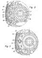
- eine Oberfräse im Vertikalschnitt in Teildarstellung, wobei nur der den Endbereich der Antriebswelle mit zugeordneter Spannzange zur Aufnahme eines Fräswerkzeugs und eine erfindungsgemäße Blockiereinrichtung enthaltende Bereich dargestellt ist,
- Fig. 2
- Die Anordnung nach Fig. 1 im Querschnitt gemäß der Schnittlinie II-II,
- Fig. 3
- die Anordnung nach Fig. 1 im Querschnitt gemäß der Schnittlinie III-III,
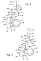
- Fig. 4
- die schematische Darstellung einer Sicherungseinrichtung der Handwerkzeugmaschine, mit der eine Betätigung der Blockiereinrichtung bei eingeschalteter Maschine sowie ein Einschalten der Maschine bei blockierter Antriebswelle verhindert wird, in dem Pfeil IV in Fig. 1 entsprechender Blickrichtung, wobei aus Fig. IV die sich bei eingeschalteter Maschine und unwirksamer Blockiereinrichtung ergebende Situation hervorgeht,
- Fig. 5
- die Anordnung nach Fig. 4, wobei die Handwerkzeugmaschine jedoch ausgeschaltet und die Antriebswelle blockiert ist.
- Fig. 1
- a router in vertical section in partial representation, only the area containing the end region of the drive shaft with associated collet for receiving a milling tool and a blocking device according to the invention is shown,
- Fig. 2
- 1 in cross section along the section line II-II,
- Fig. 3
- 1 in cross section according to section line III-III,
- Fig. 4
- the schematic representation of a safety device of the hand tool, with which an actuation of the blocking device when the machine is switched on and the machine is prevented from being switched on when the drive shaft is blocked, in the arrow IV in FIG. 1 corresponding viewing direction, with FIG. IV showing that when the machine is switched on and resulting in ineffective blocking device situation,
- Fig. 5
- the arrangement of FIG. 4, but the hand tool is turned off and the drive shaft is blocked.
Bei der aus der Zeichnung bereichsweise hervorgehenden Werkzeugmaschine handelt es sich um eine von Hand über das Werkstück zu führende Oberfräse, die mit Ausnahme der erfindungsgemäßen Blockiereinrichtung und zugehöriger Sicherungseinrichtung einen üblichen Aufbau aufweist, so dass sich eine Beschreibung der sonstigen Konstruktion der Oberfräse erübrigt.In the machine tool emerging from the drawing in some areas it is a hand over the workpiece router to be used, with the exception of the invention Blocking device and associated safety device has a usual structure, so that a description the other construction of the router is unnecessary.
Die Oberfräse weist eine beim Betrieb um eine Rotationsachse
1 rotierende Antriebswelle 2 auf, die von einem nicht dargestellten
Antriebsmotor her angetrieben wird. Am aus dem Maschinengehäuse
3 ragenden Endbereich der Antriebswelle 2 ist ein
Innenkonus 4 ausgebildet. In den Endbereich der Antriebswelle
2 ist eine Spannzange 5 eingesetzt, die einen dem
Innenkonus 4 entsprechenden Außenkonus 6 bildet. Die Spannzange
5 weist axial gerichtete Schlitze 7 auf, durch die die
Spannzangenwandung in durch die Schlitze voneinander getrennte,
leistenartig längliche Klemmbacken unterteilt wird.The router has one around an axis of rotation during
Am aus der Antriebswelle 2 vorstehenden Ende der Spannzange 5
ist am Außenumfang eine umlaufende, sich zum Spannzangenende
hin verjüngende Kegelfläche 9 ausgebildet, die mit einer entsprechenden
Kegelfläche 10 zusammenwirkt, die am Innenumfang
einer als Überwurfmutter ausgebildeten Befestigungsmutter 11
angeordnet ist. Die Befestigungsmutter 11 weist an ihrem der
Kegelfläche 10 entgegengesetzten Bereich 12 ein Innengewinde
13 auf, mit dem sie auf ein Außengewinde 14 an der Antriebswelle
2 aufgeschraubt ist. Beim Verdrehen der Befestigungsmutter
11 im Sinne eines Aufschraubens wird die Kegelfläche 10
der Befestigungsmutter 11 gegen die Kegelfläche 9 der Spannzange
5 gedrückt, so dass auf die Klemmbacken 8 eine Kraft
in radialer Richtung einwirkt und ein mit seinem Schaft in
die Spannzange 5 eingestecktes, zur Werkstückbearbeitung bestimmtes
Fräswerkzeug festgespannt wird.At the end of the
Die Befestigungsmutter 11 liegt frei, so dass sie von außen
her zugänglich ist und mittels eines Drehwerkzeugs verdreht
werden kann. Das Drehwerkzeug kann beispielsweise ein Mehrkant-Schraubenschlüssel
sein, der an eine entsprechend mehrkantige
Außenumfangsfläche der Befestigungsmutter 11 angesetzt wird.
Beim Verdrehen in die eine Richtung wird die Befestigungsmutter
11 unter festem Verspannen des Bearbeitungswerkzeugs
festgezogen. Will man das Bearbeitungswerkzeug entfernen,
muss die Befestigungsmutter 11 in entgegengesetzter Richtung
verdreht werden, so dass die Verspannung gelöst wird.The fastening
Insbesondere beim Lösen der Schraubverbindung zwischen der
Befestigungsmutter 11 und der Antriebswelle 2 ist es erforderlich,
dass die Antriebswelle 2 festgehalten wird. Wäre dies
anders, würde sich die Antriebswelle 2 beim Verdrehen der Befestigungsmutter
11 mitdrehen, so dass die Schraubverbindung
unverändert bestehen bleiben würde.Especially when loosening the screw connection between the
Fastening
Daher ist der Antriebswelle 2 eine Blockiereinrichtung 16 zugeordnet,
mit der die Antriebswelle 2 blockiert werden kann.
Dieses Blockieren kann wahlweise in der einen oder anderen
Drehrichtung erfolgen, so dass man die Antriebswelle auch
beim Festziehen der Befestigungsmutter 11 festhalten kann.A
Die Blockiereinrichtung 16 enthält ein drehfest mit der
Antriebswelle 2 verbundenes, koaxial zur Antriebswelle 2 angeordnetes
Blockier-Zahnrad 17, das beim Ausführungsbeispiel
eine umlaufende Außenverzahnung 18 aufweist. Das Blockier-Zahnrad
17 kann innerhalb des Maschinengehäuses 3 angeordnet
sein. Dem Blockier-Zahnrad 17 ist ein von Hand von außen her
betätigbarer Klinkenhebel 19 zugeordnet, der um eine ortsfest
an der Werkzeugmaschine angeordnete, parallel zur Antriebswelle
2 verlaufende Schwenkachse 20 schwenkbar ist. Beim
zweckmäßigen Ausführungsbeispiel handelt es sich bei dem
Klinkenhebel 19 um einen zweiarmigen Hebel, der in Umfangsrichtung
des Zahnrads 17 gesehen beiderseits der Schwenkachse
20 jeweils einen Hebelarm 21 bzw. 22 bildet. Jeder Hebelarm
21,22 weist an seiner dem Zahnrad 27 zugewandten Seite eine
von mindestens einem Zahn oder einer Zahnlücke gebildete Verzahnungseinrichtung
23 bzw. 24 auf, die der Verzahnung 18 des
Zahnrades 17 zugeordnet ist.The
In Fig. 2 befindet sich der Klinkenhebel 19 in seiner Ausgangsstellung,
in der die beiden Verzahnungseinrichtungen 23,24 dem
Zahnrad 17 mit Abstand gegenüberliegen, so dass der Klinkenhebel
19 außer Eingriff mit dem Blockier-Zahnrad 17 steht.
Der Klinkenhebel 19 wird durch Federkraft in dieser Ausgangsstellung
gehalten.2, the
The
Aus der genannten Ausgangsstellung lässt sich der Klinkenhebel
19 entgegen der Federkraft in die eine oder andere
Richtung verschwenken, so dass er in zwei einander entgegengesetzte
Blockierstellungen verschwenkt werden kann, in denen
entweder die eine Verzahnungseinrichtung 23 oder die andere
Verzahnungseinrichtung 24 mit dem Zahnrad 17 in Verzahnungseingriff
steht (in Fig. 5 greift die Verzahnungseinrichtung 23
in die Zahnrad-Verzahnung 18 ein). In jeder Blockierstellung
ist das Zahnrad 18 gegen ein Verdrehen in der entsprechenden
Drehrichtung blockiert, die von außen her gegen die betreffende
Verzahnungseinrichtung 23,24 gerichtet ist. Im Falle der
Fig. 5 ist das Zahnrad 17 gegen ein Verdrehen in Richtung
gemäß Pfeil 25 gesichert. In entgegengesetzter Richtung kann
das Zahnrad 17 dagegen an der mit ihm in Eingriff stehenden
Verzahnungseinrichtung, im Falle der Fig. 5 die Verzahnungseinrichtung
23, vorbeiratschen. Bei diesem Vorbeiratschen
rutscht der Klinkenhebel mit seiner betreffenden Verzahnungseinrichtung
über das Zahnrad 17 und führt dabei eine der Verzahnung
18 entsprechende, hin und her gehende Schwenkbewegung
aus.The ratchet lever can be released from the above-mentioned
Somit kann die drehfest mit dem Zahnrad 17 verbundene Antriebswelle
2 wahlweise in beiden Drehrichtungen blockiert werden,
je nach dem, in welche Richtung man den Klinkenhebel 19 verschwenkt.
Somit ist es im Falle des Ausführungsbeispiels mit
dem zweiarmigen Klinkenhebel 19 möglich, die Antriebswelle 2
sowohl beim Lösen als auch beim Festziehen der Befestigungsmutter
11 zu blockieren.Thus, the drive shaft non-rotatably connected to the
Zwischen der Befestigungsmutter 11 und der Antriebswelle 2
ist eine Reibungskraft wirksam, so dass die Antriebswelle 2
beim Verdrehen der Befestigungsmutter 11 mittels des Drehwerkzeugs
in der der blockierten Drehrichtung entgegengesetzten
Drehrichtung mitgenommen wird. Dies wird beim Ausführungsbeispiel
dadurch erreicht, dass zwischen der Befestigungsmutter
11 und der Spannzange 5 ein Mitnahme-Reibring 26 angeordnet
ist. Anstelle der Spannzange 5 könnte der Reibring auch an
einem anderen drehfest mit der Antriebswelle 2 verbundenen Teil
oder unmittelbar an der Antriebswelle 2 angreifen.Between the
Somit ist es beispielsweise zum Lösen der Befestigungsmutter 11
möglich, die Befestigungsmutter 11 bei blockierter Antriebswelle
2 in Löserichtung ein Stück weit zu verdrehen, die z.B.
dem Pfeil 25 in Fig. 5 entspricht, wonach man die Befestigungsmutter
11 bei angesetzt bleibendem Drehwerkzeug unter Mitnahme
der Antriebswelle 2 zurückdreht (hierbei ratscht das Zahnrad
17 an der betreffenden Verzahnungseinrichtung 23 vorbei). Anschließend
kann dann die Befestigungsmutter 11 erneut bei
blockierter Antriebswelle 2 in Löserichtung gedreht werden.It is thus, for example, for loosening the
Zweckmäßigerweise ist der Klinkenhebel 19 mittels einer ersten
Federeinrichtung 27,28 (siehe Fig. 2) federnd an einem um die
Schwenkachse 20 schwenkbaren Betätigungselement 31 abgestützt,
das seinerseits mittels einer zweiten Federeinrichtung 29,
30 (siehe Fig. 3) federnd gegen das Maschinengehäuse 3, beim
Ausführungsbeispiel gegen einen Lagerflansch 32 eines der Antriebswelle
2 zugeordneten Lagers 33, abgestützt ist. Die
zweite Federeinrichtung 29,30 hält das Betätigungselement 31
und mit diesem den Klinkenhebel 19 in der Ausgangsstellung.
Wird das Betätigungselement 31 vom Benutzer in die eine oder
andere Richtung verschwenkt, was entgegen der Kraft der zweiten
Federeinrichtung 29,30 erfolgt, wird der Klinkenhebel 19
über die erste Federeinrichtung 27,28 mitgenommen. In der jeweiligen
Blockierstellung, die durch Drücken gegen die betreffende
Seite des Betätigungselementes 31 erreicht wird,
ist das Betätigungselement 31 relativ zum Klinkenhebel 19
weiter verschwenkt.The
Da der Klinkenhebel 19 vom Benutzer nicht unmittelbar sondern
mittelbar über das Betätigungselement 31 betätigt wird und da
zwischen den Klinkenhebel 19 und das Betätigungselement 31 die
erste Federeinrichtung 27,28 zwischengeschaltet ist, wirkt
sich das Hin- und Herschwenken des Klinkenhebels 19 beim Vorbeiratschen
des Zahnrads 17 nicht auf die Hand des Benutzers
aus.Since the
Das Betätigungselement 31 ist nach Art einer auf der Schwenkachse
20 sitzenden Wippe mit zwei jeweils einem Arm 21 bzw.
22 des Klinkenhebels 19 zugeordneten Wippenarmen 34,35 ausgebildet.
Dabei kann das Betätigungselement 31 eine an der dem
Blockier-Zahnrad 17 zugewandten Seite offene Ausnehmung 36 aufweisen,
in die der Klinkenhebel 19 eintaucht.The
Die erste Federeinrichtung und die zweite Federeinrichtung
werden zweckmäßigerweise jeweils von zwei beiderseits der
Schwenkachse 20 angeordneten Federn 27,28 bzw. 29,30 gebildet.
Wie aus den Fig. 1 bis 3 hervorgeht, sind die beiden Federeinrichtungen
27,28 und 29,30 in axialer Richtung der Antriebswelle
2 versetzt zueinander angeordnet.The first spring device and the second spring device
are expediently by two on both sides of the
Die beschriebene Blockiereinrichtung kann nicht nur bei Oberfräsen sondern auch bei anderen Werkzeugmaschinen, insbesondere bei Handwerkzeugmaschinen verwendet werden, bei denen die Antriebswelle beim Wechsel des für die Bearbeitung des Werkstücks gedachten Bearbeitungswerkzeugs blockiert werden muss. Ferner könnte die Befestigung des Bearbeitungswerkzeugs anstelle mit einer Befestigungsmutter auch mit einer Befestigungsschraube erfolgen, wie es beispielsweise bei Kreissägen der Fall ist.The blocking device described cannot only be used for routers but also with other machine tools, in particular be used in handheld power tools where the drive shaft when changing the for machining the Machining tool intended workpiece got to. Furthermore, the attachment of the machining tool could instead of a fastening nut, also a fastening screw take place, as is the case with circular saws the case is.
Eine weitere Abwandlung besteht darin, dass man anstelle eines zweiarmigen Klinkenhebels nur einen einarmigen Klinkenhebel einsetzt. In diesem Falle liegt also nur sozusagen die Hälfte der dargestellten Blockiereinrichtung vor. Ein solcher Klinkenhebel kann nur in eine Blockierstellung verschwenkt werden. Dabei kann die blockierte Drehrichtung der Antriebswelle der Löseoder der Festziehrichtung der Befestigungsmutter oder Befestigungsschraube entsprechen, je nach dem, ob man die Antriebswelle beim Lösen oder Festziehen blockieren will.Another variation is that instead of one two-armed ratchet lever only one armed ratchet lever starts. In this case, only half lies, so to speak the blocking device shown. Such a ratchet lever can only be swiveled into a blocking position. there the blocked direction of rotation of the drive shaft of the release or the tightening direction of the fastening nut or fastening screw correspond, depending on whether you have the drive shaft wants to block when loosening or tightening.
Bei der dargestellten Maschine ist ferner noch eine aus den
Fig. 4 und 5 schematisch hervorgehende Sicherungseinrichtung
vorhanden, die in zweierlei Hinsicht Sicherheit schafft:
Dabei wird vorab darauf hingewiesen, dass die Werkzeugmaschine
einen mit der Hand betätigbaren Handschalter 37 zum Ein- und
Ausschalten ihres Antriebsmotors aufweist. Dabei ist der Handschalter
37 beim Ausführungsbeispiel ein in lineaerer Richtung
im wesentlichen parallel zur Schwenkachse 20, in den Fig.
4 und 5 also senkrecht zur Zeichenebene, bewegbarer Druckschalter.In the illustrated machine there is also a safety device, which is shown schematically in FIGS. 4 and 5 and which provides safety in two respects:
It is pointed out in advance that the machine tool has a
Die genannte Sicherungseinrichtung 38 verhindert zum einen,
dass bei in die Blockierstellung verschwenktem Klinkenhebel
19 (Fig. 5), in der die blockierte Drehrichtung 25 der Rotationsrichtung
des Bearbeitungswerkzeugs entspricht, der Handschalter
37 aus seiner die Maschine im Ausschaltzustand haltenden
Ausschaltlage in die die Maschine einschaltende Einschaltlage
bewegt werden kann.The
Zum anderen verhindert die Sicherungseinrichtung 38, dass der
Klinkenhebel aus seiner Eingangslage in die Blockierstellung
verschwenkt werden kann, wenn der Handschalter 37 in seine
Einschaltlage bewegt und somit die Werkzeugmaschine eingeschaltet
worden ist.On the other hand, the securing
Im einzelnen enthält die Sicherungseinrichtung 38 beim Ausführungsbeispiel
ein Schwenkelement 39, das um eine ortsfest
am Maschinengehäuse 3 angeordnete, zur Schwenkachse 20 des
Klinkenhebels 19 parallele Anlenkachse 40 schwenkbar ist. In detail, the securing
Das Schwenkelement 39 weist einerseits eine Mitnahmepartie 41
auf, die einer Anschlagfläche 42 am Betätigungselement 31 zugeordnet
ist. Die Anschlagfläche könnte prinzipiell anstelle
am Betätigungselement 31 am Klinkenhebel 19 selbst angeordnet
sein. Das Schwenkelement 39 ist durch eine Federkraft gemäß
Pfeil 43 so beaufschlagt, dass die Mitnahmepartie 41 gegen
die Anschlagfläche 42 gehalten wird. Das Schwenkelement 39 bildet
andererseits eine Sperrpartie 44, die einer quer zur Anlenkachse
40 angeordneten Verriegelungsausnehmung 45 und einer
seitlichen Anlagefläche 46 des Handschalters 37 zugeordnet ist.
Befindet sich der Klinkenhebel 19 in seiner Ausgangsstellung
(Fig. 4), ist die Sperrpartie 44 neben der senkrecht zur
Zeichenebene der Fig. 4 und 5 verlaufenden seitlichen Anlagefläche
46 angeordnet. Der ebenfalls senkrecht zur Zeichenebene
verlaufende Bewegungsweg des Handschalters 37 verläuft
somit an der Sperrpartie 44 vorbei. Dabei liegt die zur
Sperrpartie 44 hin offene Verriegelungsausnehmung 45 in der
Ausschaltlage des Handschalters 37 der Sperrpartie 44 gegenüber
und befindet sich somit im Schwenkweg der Sperrpartie 44.On the one hand, the
Auf diese Weise kann die Werkzeugmaschine bei unwirksamem
Klinkenhebel 19 (Fig. 4) durch Betätigen des Handschalters 37
eingeschaltet werden. Die Verriegelungsausnehmung 45 des Handschalters
befindet sich dann nicht im Schwenkweg der Sperrpartie
44, so dass die Sperrpartie 44, will man den Klinkenhebel 19
betätigen, gegen die seitliche Anlagefläche 46 stößt und
der Klinkenhebel 23 somit nicht verschwenkt werden kann.In this way, the machine tool can be ineffective
Pawl lever 19 (FIG. 4) by actuating the
Befindet sich der Handschalter 37 dagegen in seiner Ausschaltlage
(Fig. 5), kann der Klinkenhebel 19 unter Eintauchen der
Sperrpartie 44 in die Verriegelungsausnehmung 45 in seine
Blockierstellung überführt werden. Nunmehr kann der Handschalter
37 nicht mehr bewegt werden.The
Beim Ausführungsbeispiel ist das Schwenkelement 39 mehrarmig
ausgebildet, wobei an einem ersten Arm 47 die Mitnahmepartie 41
und an einem zweiten Arm 48 die Sperrpartie 45 angeornet ist
und an einem dritten Arm 48 die Federkraft 43 angreift.In the exemplary embodiment, the
Claims (8)
Applications Claiming Priority (2)
| Application Number | Priority Date | Filing Date | Title |
|---|---|---|---|
| DE10227983 | 2002-06-22 | ||
| DE2002127983 DE10227983C1 (en) | 2002-06-22 | 2002-06-22 | Hand machining tool with blocking device for blocking rotation of its drive shaft during attachment of tool to drive shaft |
Publications (3)
| Publication Number | Publication Date |
|---|---|
| EP1375080A2 true EP1375080A2 (en) | 2004-01-02 |
| EP1375080A3 EP1375080A3 (en) | 2007-09-19 |
| EP1375080B1 EP1375080B1 (en) | 2010-04-28 |
Family
ID=29285717
Family Applications (1)
| Application Number | Title | Priority Date | Filing Date |
|---|---|---|---|
| EP20030006698 Expired - Lifetime EP1375080B1 (en) | 2002-06-22 | 2003-03-26 | Machine-tool having a locking mechanism to lock it's drive shaft |
Country Status (2)
| Country | Link |
|---|---|
| EP (1) | EP1375080B1 (en) |
| DE (2) | DE10227983C1 (en) |
Cited By (1)
| Publication number | Priority date | Publication date | Assignee | Title |
|---|---|---|---|---|
| DE102020200922A1 (en) | 2020-01-27 | 2021-07-29 | Robert Bosch Gesellschaft mit beschränkter Haftung | Jig |
Families Citing this family (4)
| Publication number | Priority date | Publication date | Assignee | Title |
|---|---|---|---|---|
| DE102004009590A1 (en) * | 2004-02-25 | 2005-09-15 | Thyssenkrupp Presta Steertec Gmbh | Device for hydraulic balancing of rotary slide valves |
| NL1033187C2 (en) * | 2007-01-08 | 2008-07-09 | Bosch Gmbh Robert | Electric tools, such as an angle grinder. |
| US8075229B2 (en) | 2007-06-26 | 2011-12-13 | Techtronic Power Tools Technology Limited | Multi-speed drill and chuck assembly |
| US8057134B2 (en) | 2007-06-26 | 2011-11-15 | Techtronic Power Tools Technology Limited | Chuck assembly |
Citations (9)
| Publication number | Priority date | Publication date | Assignee | Title |
|---|---|---|---|---|
| US4448098A (en) * | 1982-03-10 | 1984-05-15 | Katsuyuki Totsu | Electrically driven screw-driver |
| US4696208A (en) * | 1985-12-13 | 1987-09-29 | Lay Tsay T | Direction-changeable structure of hand tool handle |
| US4754669A (en) * | 1985-10-24 | 1988-07-05 | Black & Decker Inc. | Motor driven screwdriver with spindle lock |
| DE4128651A1 (en) * | 1991-08-29 | 1993-03-04 | Gardena Kress & Kastner Gmbh | Electric screwdriver with reverse and manual switch settings - has ratchet-and-pawl arrangements in gearbox allowing optional manual screw-driving or withdrawal with motor inoperative |
| DE4239559A1 (en) * | 1992-11-25 | 1994-05-26 | Festo Kg | Portable power tool, e.g. circular saw, with spindle lock for tool changing - has socket spanner with spigot that passes through bore of clamping screw and spindle and automatically locks spindle by entering locking hole on pitch circle of motor cooling fan |
| US5576501A (en) * | 1996-01-03 | 1996-11-19 | Huang; Chin-Tan | Torque-controlling ratchet connector structure |
| DE19753304A1 (en) * | 1997-12-02 | 1999-06-10 | Scintilla Ag | Device for locking a shaft |
| US6098500A (en) * | 1998-12-11 | 2000-08-08 | Joda Enterprises, Inc. | Hand tool with ratchet handle and associated quick release mechanism |
| US20020020264A1 (en) * | 2000-08-17 | 2002-02-21 | Markus Hartmann | Electric power tool with locking mechanism |
-
2002
- 2002-06-22 DE DE2002127983 patent/DE10227983C1/en not_active Expired - Fee Related
-
2003
- 2003-03-26 EP EP20030006698 patent/EP1375080B1/en not_active Expired - Lifetime
- 2003-03-26 DE DE50312653T patent/DE50312653D1/en not_active Expired - Lifetime
Patent Citations (9)
| Publication number | Priority date | Publication date | Assignee | Title |
|---|---|---|---|---|
| US4448098A (en) * | 1982-03-10 | 1984-05-15 | Katsuyuki Totsu | Electrically driven screw-driver |
| US4754669A (en) * | 1985-10-24 | 1988-07-05 | Black & Decker Inc. | Motor driven screwdriver with spindle lock |
| US4696208A (en) * | 1985-12-13 | 1987-09-29 | Lay Tsay T | Direction-changeable structure of hand tool handle |
| DE4128651A1 (en) * | 1991-08-29 | 1993-03-04 | Gardena Kress & Kastner Gmbh | Electric screwdriver with reverse and manual switch settings - has ratchet-and-pawl arrangements in gearbox allowing optional manual screw-driving or withdrawal with motor inoperative |
| DE4239559A1 (en) * | 1992-11-25 | 1994-05-26 | Festo Kg | Portable power tool, e.g. circular saw, with spindle lock for tool changing - has socket spanner with spigot that passes through bore of clamping screw and spindle and automatically locks spindle by entering locking hole on pitch circle of motor cooling fan |
| US5576501A (en) * | 1996-01-03 | 1996-11-19 | Huang; Chin-Tan | Torque-controlling ratchet connector structure |
| DE19753304A1 (en) * | 1997-12-02 | 1999-06-10 | Scintilla Ag | Device for locking a shaft |
| US6098500A (en) * | 1998-12-11 | 2000-08-08 | Joda Enterprises, Inc. | Hand tool with ratchet handle and associated quick release mechanism |
| US20020020264A1 (en) * | 2000-08-17 | 2002-02-21 | Markus Hartmann | Electric power tool with locking mechanism |
Cited By (1)
| Publication number | Priority date | Publication date | Assignee | Title |
|---|---|---|---|---|
| DE102020200922A1 (en) | 2020-01-27 | 2021-07-29 | Robert Bosch Gesellschaft mit beschränkter Haftung | Jig |
Also Published As
| Publication number | Publication date |
|---|---|
| DE50312653D1 (en) | 2010-06-10 |
| EP1375080B1 (en) | 2010-04-28 |
| DE10227983C1 (en) | 2003-11-27 |
| EP1375080A3 (en) | 2007-09-19 |
Similar Documents
| Publication | Publication Date | Title |
|---|---|---|
| EP0650805B1 (en) | Electric power tool | |
| EP1112155B1 (en) | Chain saw with a chain tensioning device with a safety clutch system | |
| DE60034395T2 (en) | Coupling for rotating cutting tool | |
| DE10258372B4 (en) | tensioning assembly | |
| DE102006055014A1 (en) | Additional handle with eccentric clamping lever for a hand tool | |
| EP1618990B1 (en) | Power tool, especially angle grinder | |
| WO1988005386A1 (en) | Clamping device for axially tightening a tool, in particular a disk | |
| EP0336930B1 (en) | Clamping device for releasably holding a tool, in particular a disk | |
| EP2213419A1 (en) | Hand-held power tool with tensioning device for a tool | |
| DE1478828A1 (en) | Motor-driven screwdriver | |
| EP0680798A1 (en) | Keyless chuck | |
| DE102006001986A1 (en) | Clamping device for releasably securing a disc-shaped tool | |
| EP2851155A2 (en) | Ratchet with fine toothing | |
| DE102007044251A1 (en) | Torque tool and method for tightening or loosening connections | |
| DE19654272A1 (en) | Powered tool, especially hammer | |
| DE602004003267T2 (en) | Footplate clamping device for a power tool and a power tool with such a clamping device | |
| DE19606795C2 (en) | Drill chuck | |
| EP0577981A2 (en) | Head for a medical or dental handpiece comprising an oscillating treatment tool | |
| DE4328595A1 (en) | Manual screwdriver with cranked shaft - which can be locked to handle or become freely rotating by switching shaft end between two recesses side-by-side at bottom of handle bore | |
| EP1952947A1 (en) | Hand-held power driven tool for drilling and/or screwing | |
| DE102006000294A1 (en) | Hand tool with protective hood | |
| EP0333731A1 (en) | Portable hand tool, in particular angled grinding machine | |
| EP0050238A1 (en) | Adjustment device for an adjustable machine element, particularly for a drive-belt tensioning device comprising a tensioning strap | |
| DE4239559C2 (en) | Hand tool with a blocking device for blocking the tool spindle when changing tools | |
| EP0612589B1 (en) | Control device for electric tools |
Legal Events
| Date | Code | Title | Description |
|---|---|---|---|
| PUAI | Public reference made under article 153(3) epc to a published international application that has entered the european phase |
Free format text: ORIGINAL CODE: 0009012 |
|
| AK | Designated contracting states |
Kind code of ref document: A2 Designated state(s): AT BE BG CH CY CZ DE DK EE ES FI FR GB GR HU IE IT LI LU MC NL PT RO SE SI SK TR |
|
| AX | Request for extension of the european patent |
Extension state: AL LT LV MK |
|
| PUAL | Search report despatched |
Free format text: ORIGINAL CODE: 0009013 |
|
| AK | Designated contracting states |
Kind code of ref document: A3 Designated state(s): AT BE BG CH CY CZ DE DK EE ES FI FR GB GR HU IE IT LI LU MC NL PT RO SE SI SK TR |
|
| AX | Request for extension of the european patent |
Extension state: AL LT LV MK |
|
| 17P | Request for examination filed |
Effective date: 20070927 |
|
| 17Q | First examination report despatched |
Effective date: 20080313 |
|
| AKX | Designation fees paid |
Designated state(s): CH DE FR GB IT LI |
|
| GRAP | Despatch of communication of intention to grant a patent |
Free format text: ORIGINAL CODE: EPIDOSNIGR1 |
|
| GRAS | Grant fee paid |
Free format text: ORIGINAL CODE: EPIDOSNIGR3 |
|
| GRAA | (expected) grant |
Free format text: ORIGINAL CODE: 0009210 |
|
| AK | Designated contracting states |
Kind code of ref document: B1 Designated state(s): CH DE FR GB IT LI |
|
| REG | Reference to a national code |
Ref country code: GB Ref legal event code: FG4D Free format text: NOT ENGLISH |
|
| REG | Reference to a national code |
Ref country code: CH Ref legal event code: EP |
|
| REF | Corresponds to: |
Ref document number: 50312653 Country of ref document: DE Date of ref document: 20100610 Kind code of ref document: P |
|
| PLBE | No opposition filed within time limit |
Free format text: ORIGINAL CODE: 0009261 |
|
| STAA | Information on the status of an ep patent application or granted ep patent |
Free format text: STATUS: NO OPPOSITION FILED WITHIN TIME LIMIT |
|
| PG25 | Lapsed in a contracting state [announced via postgrant information from national office to epo] |
Ref country code: IT Free format text: LAPSE BECAUSE OF FAILURE TO SUBMIT A TRANSLATION OF THE DESCRIPTION OR TO PAY THE FEE WITHIN THE PRESCRIBED TIME-LIMIT Effective date: 20100428 |
|
| 26N | No opposition filed |
Effective date: 20110131 |
|
| REG | Reference to a national code |
Ref country code: CH Ref legal event code: PL |
|
| PG25 | Lapsed in a contracting state [announced via postgrant information from national office to epo] |
Ref country code: CH Free format text: LAPSE BECAUSE OF NON-PAYMENT OF DUE FEES Effective date: 20110331 Ref country code: LI Free format text: LAPSE BECAUSE OF NON-PAYMENT OF DUE FEES Effective date: 20110331 |
|
| REG | Reference to a national code |
Ref country code: DE Ref legal event code: R082 Ref document number: 50312653 Country of ref document: DE Representative=s name: PATENTANWAELTE MAGENBAUER & KOLLEGEN, DE |
|
| REG | Reference to a national code |
Ref country code: DE Ref legal event code: R081 Ref document number: 50312653 Country of ref document: DE Owner name: FESTOOL GROUP GMBH & CO. KG, DE Free format text: FORMER OWNER: FESTOOL GMBH, 73240 WENDLINGEN, DE Effective date: 20121119 Ref country code: DE Ref legal event code: R082 Ref document number: 50312653 Country of ref document: DE Representative=s name: PATENTANWAELTE MAGENBAUER & KOLLEGEN, DE Effective date: 20121119 Ref country code: DE Ref legal event code: R081 Ref document number: 50312653 Country of ref document: DE Owner name: FESTOOL GMBH, DE Free format text: FORMER OWNER: FESTOOL GMBH, 73240 WENDLINGEN, DE Effective date: 20121119 Ref country code: DE Ref legal event code: R082 Ref document number: 50312653 Country of ref document: DE Representative=s name: PATENTANWAELTE MAGENBAUER & KOLLEGEN PARTNERSC, DE Effective date: 20121119 |
|
| REG | Reference to a national code |
Ref country code: DE Ref legal event code: R082 Ref document number: 50312653 Country of ref document: DE Representative=s name: PATENTANWAELTE MAGENBAUER & KOLLEGEN PARTNERSC, DE |
|
| REG | Reference to a national code |
Ref country code: DE Ref legal event code: R082 Ref document number: 50312653 Country of ref document: DE Representative=s name: PATENTANWAELTE MAGENBAUER & KOLLEGEN PARTNERSC, DE Effective date: 20141104 Ref country code: DE Ref legal event code: R081 Ref document number: 50312653 Country of ref document: DE Owner name: FESTOOL GMBH, DE Free format text: FORMER OWNER: FESTOOL GROUP GMBH & CO. KG, 73240 WENDLINGEN, DE Effective date: 20141104 |
|
| REG | Reference to a national code |
Ref country code: FR Ref legal event code: PLFP Year of fee payment: 14 |
|
| REG | Reference to a national code |
Ref country code: FR Ref legal event code: PLFP Year of fee payment: 15 |
|
| REG | Reference to a national code |
Ref country code: FR Ref legal event code: PLFP Year of fee payment: 16 |
|
| PGFP | Annual fee paid to national office [announced via postgrant information from national office to epo] |
Ref country code: GB Payment date: 20220324 Year of fee payment: 20 Ref country code: DE Payment date: 20220120 Year of fee payment: 20 |
|
| PGFP | Annual fee paid to national office [announced via postgrant information from national office to epo] |
Ref country code: FR Payment date: 20220322 Year of fee payment: 20 |
|
| REG | Reference to a national code |
Ref country code: DE Ref legal event code: R071 Ref document number: 50312653 Country of ref document: DE |
|
| REG | Reference to a national code |
Ref country code: GB Ref legal event code: PE20 Expiry date: 20230325 |
|
| PG25 | Lapsed in a contracting state [announced via postgrant information from national office to epo] |
Ref country code: GB Free format text: LAPSE BECAUSE OF EXPIRATION OF PROTECTION Effective date: 20230325 |
|
| P01 | Opt-out of the competence of the unified patent court (upc) registered |
Effective date: 20230519 |