EP1376163A2 - Process of preparing films comprising polymerised liquid crystal material - Google Patents
Process of preparing films comprising polymerised liquid crystal material Download PDFInfo
- Publication number
- EP1376163A2 EP1376163A2 EP03012148A EP03012148A EP1376163A2 EP 1376163 A2 EP1376163 A2 EP 1376163A2 EP 03012148 A EP03012148 A EP 03012148A EP 03012148 A EP03012148 A EP 03012148A EP 1376163 A2 EP1376163 A2 EP 1376163A2
- Authority
- EP
- European Patent Office
- Prior art keywords
- film
- polymerisable
- polymerised
- orientation
- planar
- Prior art date
- Legal status (The legal status is an assumption and is not a legal conclusion. Google has not performed a legal analysis and makes no representation as to the accuracy of the status listed.)
- Granted
Links
- 239000004973 liquid crystal related substance Substances 0.000 title claims abstract description 193
- 239000000463 material Substances 0.000 title claims abstract description 107
- 238000000034 method Methods 0.000 title claims abstract description 44
- 230000008569 process Effects 0.000 title claims abstract description 29
- 230000003287 optical effect Effects 0.000 claims abstract description 16
- 150000001875 compounds Chemical class 0.000 claims description 74
- 239000000758 substrate Substances 0.000 claims description 27
- 230000005855 radiation Effects 0.000 claims description 15
- 239000007787 solid Substances 0.000 claims description 3
- 239000010408 film Substances 0.000 description 202
- 239000000203 mixture Substances 0.000 description 38
- 238000002360 preparation method Methods 0.000 description 19
- 238000000576 coating method Methods 0.000 description 11
- -1 acryl Chemical group 0.000 description 10
- 239000011248 coating agent Substances 0.000 description 10
- YXFVVABEGXRONW-UHFFFAOYSA-N Toluene Chemical compound CC1=CC=CC=C1 YXFVVABEGXRONW-UHFFFAOYSA-N 0.000 description 9
- 239000004820 Pressure-sensitive adhesive Substances 0.000 description 7
- 125000004432 carbon atom Chemical group C* 0.000 description 7
- 238000003475 lamination Methods 0.000 description 7
- 229920000642 polymer Polymers 0.000 description 7
- 239000002904 solvent Substances 0.000 description 7
- LWRBVKNFOYUCNP-UHFFFAOYSA-N 2-methyl-1-(4-methylsulfanylphenyl)-2-morpholin-4-ylpropan-1-one Chemical compound C1=CC(SC)=CC=C1C(=O)C(C)(C)N1CCOCC1 LWRBVKNFOYUCNP-UHFFFAOYSA-N 0.000 description 6
- 125000000217 alkyl group Chemical group 0.000 description 6
- JHIVVAPYMSGYDF-UHFFFAOYSA-N cyclohexanone Chemical compound O=C1CCCCC1 JHIVVAPYMSGYDF-UHFFFAOYSA-N 0.000 description 6
- 239000002019 doping agent Substances 0.000 description 6
- 125000003545 alkoxy group Chemical group 0.000 description 5
- 238000005336 cracking Methods 0.000 description 5
- 238000004132 cross linking Methods 0.000 description 5
- 238000004519 manufacturing process Methods 0.000 description 5
- 229920003023 plastic Polymers 0.000 description 5
- 239000004033 plastic Substances 0.000 description 5
- 229920006254 polymer film Polymers 0.000 description 5
- 239000000178 monomer Substances 0.000 description 4
- 230000009467 reduction Effects 0.000 description 4
- LQZZUXJYWNFBMV-UHFFFAOYSA-N dodecan-1-ol Chemical compound CCCCCCCCCCCCO LQZZUXJYWNFBMV-UHFFFAOYSA-N 0.000 description 3
- 239000007788 liquid Substances 0.000 description 3
- 238000000016 photochemical curing Methods 0.000 description 3
- 0 *C1Oc2ccc(*Oc(cc3)ccc3O)cc2CC1 Chemical compound *C1Oc2ccc(*Oc(cc3)ccc3O)cc2CC1 0.000 description 2
- XAGFODPZIPBFFR-UHFFFAOYSA-N aluminium Chemical compound [Al] XAGFODPZIPBFFR-UHFFFAOYSA-N 0.000 description 2
- 229910052782 aluminium Inorganic materials 0.000 description 2
- 239000004411 aluminium Substances 0.000 description 2
- 239000012986 chain transfer agent Substances 0.000 description 2
- 239000003795 chemical substances by application Substances 0.000 description 2
- 230000003098 cholesteric effect Effects 0.000 description 2
- 239000003085 diluting agent Substances 0.000 description 2
- 230000007613 environmental effect Effects 0.000 description 2
- 238000009472 formulation Methods 0.000 description 2
- 125000000524 functional group Chemical group 0.000 description 2
- 239000011521 glass Substances 0.000 description 2
- 238000011065 in-situ storage Methods 0.000 description 2
- 150000002500 ions Chemical class 0.000 description 2
- 230000000704 physical effect Effects 0.000 description 2
- 150000003254 radicals Chemical class 0.000 description 2
- 238000010561 standard procedure Methods 0.000 description 2
- 239000004094 surface-active agent Substances 0.000 description 2
- MYWOJODOMFBVCB-UHFFFAOYSA-N 1,2,6-trimethylphenanthrene Chemical compound CC1=CC=C2C3=CC(C)=CC=C3C=CC2=C1C MYWOJODOMFBVCB-UHFFFAOYSA-N 0.000 description 1
- 125000004955 1,4-cyclohexylene group Chemical group [H]C1([H])C([H])([H])C([H])([*:1])C([H])([H])C([H])([H])C1([H])[*:2] 0.000 description 1
- 125000001140 1,4-phenylene group Chemical group [H]C1=C([H])C([*:2])=C([H])C([H])=C1[*:1] 0.000 description 1
- MEKOFIRRDATTAG-UHFFFAOYSA-N 2,2,5,8-tetramethyl-3,4-dihydrochromen-6-ol Chemical compound C1CC(C)(C)OC2=C1C(C)=C(O)C=C2C MEKOFIRRDATTAG-UHFFFAOYSA-N 0.000 description 1
- MDXAIQLNVHGXMG-UHFFFAOYSA-N 2,2-dimethylbutane 3-sulfanylpropanoic acid Chemical compound CCC(C)(C)C.OC(=O)CCS.OC(=O)CCS.OC(=O)CCS MDXAIQLNVHGXMG-UHFFFAOYSA-N 0.000 description 1
- GDOBGDUGIFUCJV-UHFFFAOYSA-N 2,2-dimethylbutane;2-methylprop-2-enoic acid Chemical compound CCC(C)(C)C.CC(=C)C(O)=O.CC(=C)C(O)=O.CC(=C)C(O)=O GDOBGDUGIFUCJV-UHFFFAOYSA-N 0.000 description 1
- JPEVEWTZGBSVHD-UHFFFAOYSA-N 3-ethenoxy-1-(3-ethenoxyprop-1-enoxy)prop-1-ene Chemical compound C(=C)OCC=COC=CCOC=C JPEVEWTZGBSVHD-UHFFFAOYSA-N 0.000 description 1
- OCKGFTQIICXDQW-ZEQRLZLVSA-N 5-[(1r)-1-hydroxy-2-[4-[(2r)-2-hydroxy-2-(4-methyl-1-oxo-3h-2-benzofuran-5-yl)ethyl]piperazin-1-yl]ethyl]-4-methyl-3h-2-benzofuran-1-one Chemical compound C1=C2C(=O)OCC2=C(C)C([C@@H](O)CN2CCN(CC2)C[C@H](O)C2=CC=C3C(=O)OCC3=C2C)=C1 OCKGFTQIICXDQW-ZEQRLZLVSA-N 0.000 description 1
- 241000854350 Enicospilus group Species 0.000 description 1
- 239000004593 Epoxy Substances 0.000 description 1
- 239000004890 Hydrophobing Agent Substances 0.000 description 1
- 238000003848 UV Light-Curing Methods 0.000 description 1
- OWVIRVJQDVCGQX-VSGBNLITSA-N [(4r,5r)-5-[hydroxy(diphenyl)methyl]-2,2-dimethyl-1,3-dioxolan-4-yl]-diphenylmethanol Chemical class C=1C=CC=CC=1C(O)([C@H]1[C@@H](OC(O1)(C)C)C(O)(C=1C=CC=CC=1)C=1C=CC=CC=1)C1=CC=CC=C1 OWVIRVJQDVCGQX-VSGBNLITSA-N 0.000 description 1
- DHKHKXVYLBGOIT-UHFFFAOYSA-N acetaldehyde Diethyl Acetal Natural products CCOC(C)OCC DHKHKXVYLBGOIT-UHFFFAOYSA-N 0.000 description 1
- 239000000654 additive Substances 0.000 description 1
- 230000000996 additive effect Effects 0.000 description 1
- 239000000853 adhesive Substances 0.000 description 1
- 125000004453 alkoxycarbonyl group Chemical group 0.000 description 1
- 125000005194 alkoxycarbonyloxy group Chemical group 0.000 description 1
- 125000005250 alkyl acrylate group Chemical group 0.000 description 1
- 125000004448 alkyl carbonyl group Chemical group 0.000 description 1
- 239000002518 antifoaming agent Substances 0.000 description 1
- ZDZHCHYQNPQSGG-UHFFFAOYSA-N binaphthyl group Chemical group C1(=CC=CC2=CC=CC=C12)C1=CC=CC2=CC=CC=C12 ZDZHCHYQNPQSGG-UHFFFAOYSA-N 0.000 description 1
- 125000002915 carbonyl group Chemical group [*:2]C([*:1])=O 0.000 description 1
- 125000003178 carboxy group Chemical group [H]OC(*)=O 0.000 description 1
- 239000003054 catalyst Substances 0.000 description 1
- 125000002091 cationic group Chemical group 0.000 description 1
- HVYWMOMLDIMFJA-DPAQBDIFSA-N cholesterol group Chemical group [C@@H]1(CC[C@H]2[C@@H]3CC=C4C[C@@H](O)CC[C@]4(C)[C@H]3CC[C@]12C)[C@H](C)CCCC(C)C HVYWMOMLDIMFJA-DPAQBDIFSA-N 0.000 description 1
- 238000001723 curing Methods 0.000 description 1
- 230000007423 decrease Effects 0.000 description 1
- 230000003247 decreasing effect Effects 0.000 description 1
- 230000007547 defect Effects 0.000 description 1
- 230000032798 delamination Effects 0.000 description 1
- 125000004386 diacrylate group Chemical group 0.000 description 1
- 239000002270 dispersing agent Substances 0.000 description 1
- WNAHIZMDSQCWRP-UHFFFAOYSA-N dodecane-1-thiol Chemical compound CCCCCCCCCCCCS WNAHIZMDSQCWRP-UHFFFAOYSA-N 0.000 description 1
- 239000000975 dye Substances 0.000 description 1
- 230000000694 effects Effects 0.000 description 1
- 230000008020 evaporation Effects 0.000 description 1
- 238000001704 evaporation Methods 0.000 description 1
- NBVXSUQYWXRMNV-UHFFFAOYSA-N fluoromethane Chemical compound FC NBVXSUQYWXRMNV-UHFFFAOYSA-N 0.000 description 1
- 230000009477 glass transition Effects 0.000 description 1
- IHPDTPWNFBQHEB-UHFFFAOYSA-N hydrobenzoin Chemical group C=1C=CC=CC=1C(O)C(O)C1=CC=CC=C1 IHPDTPWNFBQHEB-UHFFFAOYSA-N 0.000 description 1
- 239000003112 inhibitor Substances 0.000 description 1
- 239000003999 initiator Substances 0.000 description 1
- 239000000314 lubricant Substances 0.000 description 1
- 239000003550 marker Substances 0.000 description 1
- 239000011159 matrix material Substances 0.000 description 1
- 125000005641 methacryl group Chemical group 0.000 description 1
- 125000000956 methoxy group Chemical group [H]C([H])([H])O* 0.000 description 1
- 239000012788 optical film Substances 0.000 description 1
- 239000003960 organic solvent Substances 0.000 description 1
- 239000002245 particle Substances 0.000 description 1
- 239000000049 pigment Substances 0.000 description 1
- 238000006116 polymerization reaction Methods 0.000 description 1
- 230000004044 response Effects 0.000 description 1
- 238000010008 shearing Methods 0.000 description 1
- 238000004528 spin coating Methods 0.000 description 1
- 239000003381 stabilizer Substances 0.000 description 1
- 125000003011 styrenyl group Chemical group [H]\C(*)=C(/[H])C1=C([H])C([H])=C([H])C([H])=C1[H] 0.000 description 1
- 239000000126 substance Substances 0.000 description 1
- 238000004381 surface treatment Methods 0.000 description 1
- 230000004083 survival effect Effects 0.000 description 1
- 238000009281 ultraviolet germicidal irradiation Methods 0.000 description 1
- 125000000391 vinyl group Chemical group [H]C([*])=C([H])[H] 0.000 description 1
- 229920002554 vinyl polymer Polymers 0.000 description 1
- 239000000080 wetting agent Substances 0.000 description 1
Images


Classifications
-
- C—CHEMISTRY; METALLURGY
- C08—ORGANIC MACROMOLECULAR COMPOUNDS; THEIR PREPARATION OR CHEMICAL WORKING-UP; COMPOSITIONS BASED THEREON
- C08J—WORKING-UP; GENERAL PROCESSES OF COMPOUNDING; AFTER-TREATMENT NOT COVERED BY SUBCLASSES C08B, C08C, C08F, C08G or C08H
- C08J5/00—Manufacture of articles or shaped materials containing macromolecular substances
- C08J5/18—Manufacture of films or sheets
-
- G—PHYSICS
- G02—OPTICS
- G02B—OPTICAL ELEMENTS, SYSTEMS OR APPARATUS
- G02B5/00—Optical elements other than lenses
- G02B5/30—Polarising elements
- G02B5/3016—Polarising elements involving passive liquid crystal elements
-
- G—PHYSICS
- G02—OPTICS
- G02F—OPTICAL DEVICES OR ARRANGEMENTS FOR THE CONTROL OF LIGHT BY MODIFICATION OF THE OPTICAL PROPERTIES OF THE MEDIA OF THE ELEMENTS INVOLVED THEREIN; NON-LINEAR OPTICS; FREQUENCY-CHANGING OF LIGHT; OPTICAL LOGIC ELEMENTS; OPTICAL ANALOGUE/DIGITAL CONVERTERS
- G02F1/00—Devices or arrangements for the control of the intensity, colour, phase, polarisation or direction of light arriving from an independent light source, e.g. switching, gating or modulating; Non-linear optics
- G02F1/01—Devices or arrangements for the control of the intensity, colour, phase, polarisation or direction of light arriving from an independent light source, e.g. switching, gating or modulating; Non-linear optics for the control of the intensity, phase, polarisation or colour
- G02F1/13—Devices or arrangements for the control of the intensity, colour, phase, polarisation or direction of light arriving from an independent light source, e.g. switching, gating or modulating; Non-linear optics for the control of the intensity, phase, polarisation or colour based on liquid crystals, e.g. single liquid crystal display cells
- G02F1/133—Constructional arrangements; Operation of liquid crystal cells; Circuit arrangements
- G02F1/1333—Constructional arrangements; Manufacturing methods
- G02F1/1335—Structural association of cells with optical devices, e.g. polarisers or reflectors
- G02F1/13363—Birefringent elements, e.g. for optical compensation
- G02F1/133636—Birefringent elements, e.g. for optical compensation with twisted orientation, e.g. comprising helically oriented LC-molecules or a plurality of twisted birefringent sublayers
Definitions
- the invention relates to a process of preparing films and multilayers comprising polymerised liquid crystal material with uniform orientation, to films and multilayers obtained by said process and their use for optical and electrooptical applications.
- film' as used in this application includes self-supporting, i.e. free-standing, films that show more or less pronounced mechanical stability and flexibility, as well as coatings or layers on a supporting substrate or between two substrates.
- 'liquid crystal or mesogenic material' or 'liquid crystal or mesogenic compound' should denote materials or compounds comprising one or more rod-shaped, board-shaped or disk-shaped mesogenic groups, i.e. groups with the ability to induce liquid crystal phase behaviour.
- Liquid crystal compounds with rod-shaped or board-shaped groups are also known in the art as 'calamitic' liquid crystals.
- Liquid crystal compounds with a disk-shaped group are also known in the art as 'discotic' liquid crystals.
- the compounds or materials comprising mesogenic groups do not necessarily have to exhibit a liquid crystal phase themselves. It is also possible that they show liquid crystal phase behaviour only in mixtures with other compounds, or when the mesogenic compounds or materials, or the mixtures thereof, are polymerised.
- liquid crystal material' is used hereinafter for both liquid crystal materials and mesogenic materials
- 'mesogen' is used for the mesogenic groups of the material.
- the term 'director' is known in prior art and means the preferred orientation direction of the long molecular axes (in case of calamitic compounds) or short molecular axis (in case of discotic compounds) of the mesogens in a liquid crystal material.
- 'planar structure' or 'planar orientation' refers to a film wherein the optical axis is substantially parallel to the film plane.
- 'homeotropic structure' or 'homeotropic orientation' refers to a film wherein the optical axis is substantially perpendicular to the film plane, i.e. substantially parallel to the film normal.
- 'tilted structure' or 'tilted orientation' refers to a film wherein the optical axis is tilted at an angle ⁇ between 0 and 90 degrees relative to the film plane.
- 'splayed structure' or 'splayed orientation' means a tilted orientation as defined above, wherein the tilt angle additionally varies monotonuously in the range from 0 to 90 °, preferably from a minimum to a maximum value, in a direction perpendicular to the film plane.
- the optical axis of the film is given by the director of the liquid crystal material.
- the term 'helically twisted structure' relates to a film comprising one or more layers of liquid crystal material wherein the mesogens are oriented with their main molecular axis in a preferred direction within molecular sublayers, said preferred orientation direction in different sublayers being twisted at an angle ⁇ around a helix axis.
- the term 'helically twisted structure with planar orientation' means a film with helically twisted structure as described above, wherein the helix axis is substantially perpendicular to the film plane, i.e. substantially parallel to the film normal.
- Anisotropic films comprising polymerised liquid crystal (LC) material with uniform orientation are known in prior art. They are typcially used as retardation, compensation or polarisation films for LC displays or other optical or electrooptical applications. Planar LC films are described for example in WO 98/04651. Homeotropic LC films are described for example in WO 98/00475 and GB 2 324 382 A. Tilted or splayed LC films are described for example in US 5,619,352, WO 97/44409, WO 97/44702, WO 97/44703 and WO 98/12584.
- LC polymerised liquid crystal
- LC films For many applications, e.g. in liquid crystal displays, it is necessary to use as optical component a stack or multilayer of two or more LC films having the same or different orientation.
- usually macroscopically aligned LC films are supported on a plastic substrate and are manufactured on a roll to roll coating machine.
- the polymerised LC films produced are then laminated e.g. to other LC films or to polarisers.
- the lamination process typically involves applying a pressure sensitive adhesive (PSA) sheet to the film, attaching it to the desired component, and then removing the original plastic substrate. If the LC film is to be used with another LC film this must be similarly removed from its supporting substrate.
- PSA pressure sensitive adhesive
- Each lamination stage is both labour and material consumptive. Also, the use of PSA sheets increases the material costs and the thickness of the final multilayer, which is often undesired for use in flat panel displays.
- the aim of the present invention is to provide a process for preparing anisotropic films comprising polymerised LC material that do not have the drawbacks of films known from prior art and allow easy and economic fabrication even at large scales.
- Another aim of the present invention is to provide polymerised LC films that are easy to manufacture, show improved mechanical stability, in particular a reduced tendency to crack when laminated to other films, and have good optical performance when used in LC displays.
- Another aim of the present invention is to provide an improved process for preparing a stack of more than one polymerised LC film having the same or different orientation, which is less labour and material consumptive than the methods known from prior art, and allows a reduction of the number of process steps and components required.
- the above aims can be achieved by providing processes, films and multilayers of films according to the present invention.
- the inventors have found that the above aims can be achieved by a process where a film of polymerised LC material is directly prepared on another aligned liquid crystal layer that serves as substrate.
- the benefits of this process are e.g. the reduction of the amount of plastic substrate used and in particular the reduction of the number of lamination steps required. This leads to a reduction in processing costs.
- a further aspect of the invention relates to a method of improving the mechanical stability of a film comprising polymerised LC material, in particular a method of reducing the number of cracks when the film is subjected to mechanical stress e.g. when laminated to other films, by reducing the degree of crosslinking in the polymerisable material that is used for preparing the film.
- the inventors have found that the film stability increases and the number of cracks decreases when the amount of multireactive compounds (compounds with two or more polymerisable groups) in the polymerisable LC material is reduced. However, a certain amount of multireactive compounds in the polymerisable mixture is necessary to obtain a stable, self-supporting film.
- a further aspect of the invention relates to a method of controlling the tilt angle in a second polymerised LC film with homeotropic or tilted orientation, which is prepared by UV photocuring of a polymerisable LC material on a first polymerised LC film with planar orientation serving as substrate, wherein said first, planar LC film is also prepared by UV photocuring of a polymerisable liquid crystal material.
- the inventors found that the tilt angle in the second LC film can be varied from 0° (homeotropic) to higher values (tilted) by reducing the UV intensity used for photocuring of said first LC film.
- the invention relates to a process of preparing a second film comprising a second polymerised liquid crystal (LC) material with uniform orientation directly onto a first film comprising a first polymerised LC material with uniform orientation, by providing said second polymerisable LC material directly onto said first film and polymerising said second LC material.
- LC liquid crystal
- the invention further relates to a process of preparing a second film comprising a second polymerised LC material with homeotropic, tilted or splayed orientation, by providing a second polymerisable LC material onto a first film of polymerised LC material having planar orientation and polymerising it, wherein said first film having planar orientation is prepared by providing a first polymerisable LC material onto a substrate, aligning it into planar orientation and polymerising it by exposure to UV radiation, characterized in that the tilt angle in said second film having homeotropic, tilted or splayed orientation is controlled by varying the intensity of UV radiation used for polymerisation of said first film having planar orientation.
- the invention further relates to a process of preparing a second film comprising a second polymerised LC material with homeotropic, tilted or splayed orientation and having improved mechanical stability, by providing a second polymerisable LC material onto a first film of a first polymerised LC material having planar orientation and optionally having a helically twisted structure, and polymerising said second LC material, wherein said second polymerisable LC material comprises one or more polymerisable compounds having one polymerisable group (monoreactive) and one or more polymerisable compounds having two or more polymerisable groups (multireactive), characterized in that the mechanical stability of said second film is controlled by varying the amount of multireactive compounds in said second polymerisable LC material.
- the invention further relates to a film comprising polymerised LC material with homeotropic, tilted or splayed orientation, obtainable by a process as described above and below.
- the invention further relates to a multilayer comprising at least one second film comprising a second polymerised LC material with uniform orientation that is directly adjacent to at least one first film comprising a first polymerised LC material with uniform orientation, obtainable by a process as described above and below.
- the invention further relates to the use of a film or multilayer as described above and below in optical or electrooptical devices.
- the invention further relates to a liquid crystal display comprising a film or multilayer as described above and below.
- polymerised LC films in this invention is carried out according to standard methods known from the literature.
- a polymerisable LC material is coated or otherwise applied onto a substrate where it aligns into uniform orientation, and polymerised in situ in its LC phase e.g. by exposure to heat or actinic radiation, preferably by photopolymerisation, very preferably by UV-photopolymerisation, thereby fixing the alignment of the LC molecules.
- Uniform alignment can also be induced or enhanced by additional means like shearing, surface treatment of the substrate, or addition of surfactants to the LC material.
- planar LC films according to this procedure is described e.g. in WO 98/04651, the preparation of homeotropic LC films is described e.g. in WO 98/00475, the preparation of tilted or splayed LC films is described e.g. in US 5,619,352, WO 97/44702 and WO 98/12584, with the entire disclosure of all these documents being incorporated into this application by reference.
- a helically twisted LC film with planar orientation is used, this is preferably a film comprising polymerised chiral LC, in particular cholesteric LC (CLC) material with a short pitch and a reflection in the UV range, which is also known in the literature as "UVCLC” film or "highly twisted A plate” as described for example in GB 2,315,072 and WO 01/20394, the entire disclosure of which is incorporated into this application by reference.
- CLC cholesteric LC
- a first preferred embodiment of the present invention relates to a method of preparing a second film comprising second polymerised LC material with uniform orientation directly on a first film comprising first polymerised LC material with uniform orientation that serves as a substrate.
- the second polymerised LC film is prepared as described above by providing a second polymerisable LC material onto a substrate and polymerising the material in situ.
- a first polymerised LC film having planar orientation is used as substrate.
- Said first LC film having planar orientation is prepared e.g. by providing a first polymerisable LC material onto a substrate, aligning it into planar orientation and polymerising it by exposure to UV radiation, according to standard procedures that are known to the expert and are described in the literature.
- a second polymerisable LC mixture provided on said first, planar polymerised LC film aligns homeotropically and can be cured to form a second polymerised LC film.
- the polymerised LC material in the second film has homeotropic, tilted or splayed orientation.
- the orientation can further be controlled as described in the second preferred embodiment below.
- the polymerised LC material in the second film has homeotropic orientation and in the first film has planar orientation.
- the polymerised LC material in the second film has homeotropic orientation and in the first film has helically twisted structure with planar orientation.
- the polymerised LC material in the second film has tilted or splayed orientation and in the first film has planar orientation.
- the splayed film preferably has a largely continuous tilt profile, with the tilt angle preferably varying in the range from 0° to 90°, especially preferably from between 0° and 5° to between 85° and 90°.
- the on-axis retardation (i.e. at 0° viewing angle) of a splayed film is preferably from 50 nm to 150 nm, especially preferably from 70 nm and 120 nm. These values are for the splayed film measured separately from the planar film.
- the planar film preferably has a thickness of from 0.5 to 2 microns, especially preferably from 0.75 to 1.3 microns.
- the on-axis retardation of the planar film is preferably from 30 nm to 250 nm.
- the combined retardation of a bilayer film is the additive of the retardation of the two individual films.
- a second preferred embodiment of the invention relates to a method of controlling the orientation of the LC molecules in a second film comprising a second polymerised LC material, which is prepared on a first film of a first polymerised LC material having planar orientation that serves as a substrate.
- the first LC film having planar orientation is prepared e.g. by providing a first polymerisable LC material onto a substrate, aligning it into planar orientation and polymerising it by exposure to UV radiation.
- the second polymerised LC film is prepared as described above, by providing a second polymerisable LC material on said first, planar film where it aligns homeotropically, and polymerising said second material.
- Homeotropical alignment of the second LC film can be controlled by varying the amount of UV radiation that said underlying first, planar LC film serving as substrate had been subjected to during its preparation.
- a first planar LC film is used as substrate that was prepared by UV photopolymerisation of a planar aligned first LC mixture with insufficient UV intensity
- a second polymerisable LC mixture coated on said planar film does not show good homeotropic alignment.
- Good homeotropic alignment can be achieved if the first film is exposed to UV light of sufficient intensity.
- the minimum amount of UV exposure during preparation of the first planar LC film required, below which no homeotropic alignment is produced in the second LC film.
- the minimum amount of light intensity needed depends on the polymerisable mixture used.
- the amount of light intensity is preferably about 1.1 W/cm 2 or higher, however, the invention is not limited to this value.
- a third preferred embodiment of the invention relates to a method of improving the mechanical stability of a second film comprising second polymerised LC material, which is prepared on a first film of first polymerised LC material having planar orientation that serves as a substrate.
- the second polymerised LC film is prepared as described above, by providing a polymerisable LC material on said first, planar film and polymerising it.
- the second LC film preferably has homeotropic, tilted or splayed orientation.
- the polymerisable LC material used for preparation of said second film comprises at least one polymerisable compound having one polymerisable group (monoreactive) and at least one polymerisable compound having two or more polymerisable groups (multireactive).
- the mechanical stability of said second film is controlled by varying the crosslinking density in the second polymerised LC film.
- a three-dimensional polymer network is formed and the orientation of the LC material is permanently fixed.
- An optical retardation film made of such a network is self-supporting and shows a high mechanical and thermal stability and a low temperature dependence of its physical and optical properties.
- the concentration of the multireactive compounds By varying the concentration of the multireactive compounds the crosslink density of the polymer film and thereby its physical and chemical properties such as the glass transition temperature, which is also important for the temperature dependence of the optical properties of the optical retardation film, the thermal and mechanical stability or the solvent resistance can be tuned.
- the inventors found out that by varying the amount of multireactive compounds between a minimum value and a maximum value, it is possible to improve the mechanical stability of the polymerised LC film. In this way for example the number of cracks is reduced when the LC film is laminated to another film.
- the polymerisable LC material comprises one or more multireactive compounds, in particular multireactive mesogenic compounds, in an amount of from 5 to less than 42 %, preferably from 5 to 40, very preferably from 5 to 33 % by weight of the total amount of solid components in the material.
- the polymerisable LC material preferably comprises one or more monoreactive polymerisable mesogenic compounds and one or more di- or multireactive polymerisable mesogenic compounds.
- Polymerisable mesogenic mono-, di- and multireactive compounds used for the instant invention can be prepared by methods which are known per se and which are described, for example, in standard works of organic chemistry such as, for example, Houben-Weyl, Methoden der organischen Chemie, Thieme-Verlag, Stuttgart. Typical examples are described for example in WO 93/22397; EP 0 261 712; DE 19504224; DE 4408171 and DE 4405316. The compounds disclosed in these documents, however, are to be regarded merely as examples that do not limit the scope of this invention.
- liquid crystalline or mesogenic materials, compounds and polymers compounds mentioned above and below are selected from calamitic liquid crystalline or mesogenic materials, which provide good optical performance with improved chromaticity, and, especially in case of monomers, can easily and quickly be aligned into the desired orientation, which is especially important when manufacturing polymer films at large scale.
- P is a polymerizable group, preferably an acryl, methacryl, vinyl, vinyloxy, propenyl ether, epoxy or styrene group
- x and y are each independently 1 to 12
- a and D are 1,4-phenylene that is optionally mono- di or trisubstituted by L 1 or 1,4-cyclohexylene
- v is 0 or 1
- Z 0 is -COO-, -OCO-, -CH 2 CH 2 - or a single bond
- Y is a polar group
- R 0 is an unpolar alkyl or alkoxy group
- Ter is a terpenoid radical like e.g.
- L 1 and L 2 are each independently H, F, Cl, CN or an optionally halogenated alkyl, alkoxy, alkylcarbonyl, alkoxycarbonyl or alkoxycarbonyloxy group with 1 to 7 C atoms.
- 'polar group' in this connection means a group selected from F, Cl, CN, NO 2 , OH, OCH 3 , OCN, SCN, an optionally fluorinated carbonyl or carboxyl group with up to 4 C atoms or a mono- oligo- or polyfluorinated alkyl or alkoxy group with 1 to 4 C atoms.
- 'unpolar group' means an alkyl group with 1 or more, preferably 1 to 12 C atoms or an alkoxy group with 2 or more, preferably 2 to 12 C atoms.
- a preferred polymerisable liquid crystal material for the preparation of homeotropic, tilted and splayed films comprises
- the monoreactive achiral compounds are preferably selected from above formulae la-lf and li, in particular la and le, wherein v is 1.
- the direactive achiral compounds are preferably selected from above formulae lla and llb, in partiuclar lla.
- the polymerisable LC material preferably comprises one or more achiral polymerisable mesogenic compounds and at least one chiral compound.
- the chiral compound can be selected from non-polymerisable chiral compounds, like e.g. conventional chiral dopants, polymerisable chiral non-mesogenic or polymerisable chiral mesogenic compounds.
- Suitable dopants can be selected e.g. from the commercially available R or S 811, R or S 1011, R or S 2011 or CB 15 (from Merck KGaA, Darmstadt, Germany).
- Very preferred are chiral dopants with a high helical twisting power (HTP), in particular dopants comprising a sorbitol group as described in WO 98/00428, dopants comprising a hydrobenzoin group as described in GB 2,328,207, chiral binaphthyl derivatives as described in WO 02/94805, chiral binaphthol acetal derivatives as described in WO 02/34739, chiral TADDOL derivatives as described in WO 02/06265, and chiral compounds having at least one fluorinated linkage group and a terminal or central chiral group as described in WO 02/06196 and WO 02/06195.
- HTP high helical twisting power
- the polymerisable material can also be dissolved in a solvent, preferably in an organic solvent.
- a solvent preferably in an organic solvent.
- the solution is then coated onto the substrate, for example by spin-coating or other known techniques, and the solvent is evaporated off before polymerisation. In most cases it is suitable to heat the mixture in order to facilitate the evaporation of the solvent.
- Polymerisation of the LC material is preferably achieved by exposing it to actinic radiation.
- Actinic radiation means irradiation with light, like UV light, IR light or visible light, irradiation with X-rays or gamma rays or irradiation with high energy particles, such as ions or electrons.
- Preferably polymerisation is carried out by photoirradiation, in particular with UV light, very preferably with linear polarised UV light.
- a source for actinic radiation for example a single UV lamp or a set of UV lamps can be used. When using a high lamp power the curing time can be reduced.
- Another possible source for photoradiation is a laser, like e.g. a UV laser, an IR laser or a visible laser.
- Polymerisation is carried out in the presence of an initiator absorbing at the wavelength of the actinic radiation.
- an initiator absorbing at the wavelength of the actinic radiation.
- a photoinitiator can be used that decomposes under UV irradiation to produce free radicals or ions that start the polymerisation reaction.
- UV photoinitiators are preferred, in particular radicalic UV photoinitiators.
- the commercially available Irgacure® 907, Irgacure® 651, Irgacure® 184, Darocure® 1173 or Darocure® 4205 can be used, whereas in case of cationic photopolymerisation the commercially available UVI 6974 (Union Carbide) can be used.
- the polymerisable LC material can additionally comprise one or more other suitable components such as, for example, catalysts, sensitizers, stabilizers, chain-transfer agents, inhibitors, co-reacting monomers, surface-active compounds, lubricating agents, wetting agents, dispersing agents, hydrophobing agents, adhesive agents, flow improvers, defoaming agents, deaerators, diluents, reactive diluents, auxiliaries, colourants, dyes or pigments.
- suitable components such as, for example, catalysts, sensitizers, stabilizers, chain-transfer agents, inhibitors, co-reacting monomers, surface-active compounds, lubricating agents, wetting agents, dispersing agents, hydrophobing agents, adhesive agents, flow improvers, defoaming agents, deaerators, diluents, reactive diluents, auxiliaries, colourants, dyes or pigments.
- the mixture of polymerisable material comprises up to 70%, preferably 1 to 50 % of a monoreactive non-mesogenic compound with one polymerisable functional group.
- Typical examples are alkyl acrylates or alkyl methacrylates with alkyl groups of 1 to 20 C atoms.
- non-mesogenic compound with two or more polymerisable functional groups to the polymerisable LC material alternatively or in addition to the di- or multireactive polymerisable mesogenic compounds to increase crosslinking of the polymer.
- Typical examples for direactive non-mesogenic monomers are alkyl diacrylates or alkyl dimethacrylates with alkyl groups of 1 to 20 C atoms.
- Typical examples for multireactive non-mesogenic monomers are trimethylpropane trimethacrylate or pentaerythritol tetraacrylate.
- chain transfer agents such as monofunctional thiol compounds like e.g. dodecane thiol or multifunctional thiol compounds like e.g. trimethylpropane tri(3-mercaptopropionate), very preferably mesogenic or liquid crystalline thiol compounds.
- chain transfer agent When adding a chain transfer agent, the length of the free polymer chains and/or the length of the polymer chains between two crosslinks in the inventive polymer film can be controlled. When the amount of the chain transfer agent is increased, the polymer chain length in the obtained polymer film is decreasing.
- the films according to the present invention can be used as retardation or compensation films in conventional LCDs, in particular those of the DAP (deformation of aligned phases) or VA (vertically aligned) mode, like e.g. ECB (electrically controlled birefringence), CSH (colour super homeotropic), VAN or VAC (vertically aligned nematic or cholesteric) displays, MVA (multi-domain vertically aligned) or PVA (patterned vertically aligned) displays, in displays of the bend mode or hybrid type displays, like e.g.
- DAP deformation of aligned phases
- VA vertical aligned
- ECB electrically controlled birefringence
- CSH colour super homeotropic
- VAN or VAC vertically aligned nematic or cholesteric
- MVA multi-domain vertically aligned
- PVA patterned vertically aligned
- OCB optically compensated bend cell or optically compensated birefringence
- R-OCB reflective OCB
- HAN hybrid aligned nematic or pi-cell ( ⁇ -cell) displays
- AMD-TN active matrix driven TN
- IPS in plane switching
- isotropic mode displays as described for example in WO 02/93244 A1.
- VA Especially preferred are VA, MVA, PVA, OCB and pi-cell displays.
- Example 1 Preparation of a roll to roll coated homeotropically aligned LC film on a planar aligned LC film
- Polymerisable LC mixture 1A was formulated as follows Monoreactive compound (1) 32.9 % Monoreactive compound (2) 18.8 % Direactive compound (3) 42.2 % Irgacure 907 ® 5.6 % Fluorad FC171 ® 0.5 %
- the monoreactive compound (1) and its preparation are described in GB 2,280,445.
- the monoreactive compound (2) can be prepared according to or in analogy to the methods described in D.J.Broer et al., Makromol.Chem. 190 , 3201-3215 (1989).
- the direactive compound (3) can be prepared as described in WO 93/22397.
- Irgacure 907 is a commercially available photoinitiator (from Ciba AG, Basel, Switzerland).
- Fluorad FC 171 is a commercially available non-ionic fluorocarbon surfactant (from 3M).
- a 17.5% solution of mixture 1A dissolved in toluene/cyclohexanone 7:3 was prepared and filtered to 0.2 ⁇ m.
- An RK Koater was webbed with HiFi PET of 100 ⁇ m thickness.
- the substrate was rubbed with a velvet covered rubbing roller set at 1000 rpm. With the web speed set at 3 m/min the coating solution was applied with a 150 Ipi trihelical gravure rotating at 3.6 m/min. Solvent was removed with both ovens at 60°C and the mixture polymerised with the UV lamp at 60% power.
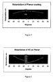
- a planar polymerised LC film produced was clear and well aligned with a thickness of 1.2 ⁇ m.
- the planar film was removed from the PET by lamination onto TAC with PSA so that the film retardation can be measured without interference from the birefringence of the PET.
- the retardation on axis was 172.2 nm and the profile is shown in Figure 1 .
- Polymerisable LC mixture 1 B was formulated as follows Monoreactive compound (1) 30.8 % Monoreactive compound (2) 21.8 % Direactive compound (3) 20.1 % Monoreactive compound (4) 21.8 % Irgacure 907 ® 5.5 %
- the monoreactive compound (4) can be prepared according to or in analogy to the methods described in D.J.Broer et al., Makromol.Chem. 190 , 3201-3215 (1989).
- the RK Koater was now set for coating the homeotropic liquid crystal layer.
- the planar film prepared according to example 1A on the PET was fed through the machine.
- a 20% solution of mixture 1B dissolved in toluene/cyclohexanone 7:3 was coated onto the planar coating on the web.
- Machine speeds and conditions were kept the same apart from the following two changes.
- the trihelical gravure was changed to 90 Ipi, and the rubbing roller was removed from the web path.
- the process produced a clear well aligned homeotropic coating on top of the planar aligned liquid crystal, with the thickness of the homeotropic layer being approximately 3 ⁇ m.
- Example 2 Durability of a homeotropically aligned LC film
- a planar LC film was prepared on the RK Koater in a similar manner to that described in example 1A above, except that the substrate used was TAC.
- a homeotropically aligned LC layer was applied to this by preparing a 30% solution of mixture 1B in toluene/cyclohexanone and using a No 3 wire wound bar. The coating was cured with 4 passes through a Minicure UV curing system at 20m/min.
- the resultant bilayer of homeotropic and planar LC film was transferred to a 50 x 70 x 0.15mm glass slide using PSA. Similar slides were produced with single planar LC film alone and with a single homeotropic LC film prepared as described in example 1. For each type of film two samples (I,II) were prepared. These slides were then placed in an environmental chamber at 60°C and 80% relative humidity. Assessments of the amount of cracking are shown in table 1 below.
- the homeotropic film readily cracked, giving long cracks (in excess of 20 mm) and eventually producing a network of cracks covering the whole area of the slide.
- the planar film showed no cracking at all.
- the homeotropic film on the planar film only started to crack after 476 hours, these being short cracks in the area where the film number was applied to the film with marker pen.
- Polymerisable LC mixture 2B with an increased amount of direactive compounds was formulated as follows Monoreactive compound (1) 32.67 % Monoreactive compound (2) 18.67 % Direactive compound (3) 21.00 % Direactive compound (5) 21.00 % Dodecanol 1.02 % BHT 0.04 % Irgacure 907 ® 5.60 %
- the monoreactive compound (6) is described in GB 2,280,445.
- the resistance to cracking is related to the degree of crosslinking, represented by the percentage of direactive compounds in the polymerisable LC mixture.
- a normally hand coated planar LC film of mixture 1A as described in example 1 was cured on a Minicure hand-coating stage with 4 passes. Samples of the planar LC film were coated and given increasing numbers of passes. The homeotropic mixture 1B was coated on top of the planar layer. The response of the layer of mixture 1B is shown below. Samples which were given a lower exposure to the UV lamp resulted in a tilted film being produced. Increasing the UV exposure gave the required homeotropic alignment.
- planar LC film was produced on the RK Koater using 60% lamp power.
- the hand coated samples were passed through the Minicure stage 4 times, receiving an inadequate dose of UV radiation.
- the amount of radiation received modifies the surface of the planar LC film, to influence the homeotropic alignment of an LC mixture coated onto said film.
- Polymerisable LC mixture 3B was formulated as follows Monoreactive compound (1) 32.7 % Monoreactive compound (2) 18.8 % Direactive compound (3) 42.0 % S-1011 0.4% Irgacure 907 ® 5.6 % Fluorad FC171® 0.5 % S-1011 is a commercially available chiral dopant (from Merck KGaA, Darmstadt, Germany).
- An LC film with helically twisted structure and planar alignment was prepared from a 25% solution of mixture 3B as generally described above and in WO 01/20394A, using a TAC substrate and a RK Koater.
- the retardation profile of the twisted A plate is shown in Figure 3 .
- a 30% solution of mixture 1B was coated onto the above prepared twisted A plate by hand using a No 3 wire wound bar.
- the solvent was allowed to evaporate and the coating cured at room temperature with 4 passes through the Minicure at 20m/min.
- a bilayer film of a homeotropic LC film on the twisted A plate was obtained. The resultant film was clear and well aligned.
- the on axis retardation value for the twisted A plate alone is 118.1 nm. For the combined films this value is 108.2 nm. The agreement on these figures indicates that the second LC film has aligned homeotropically.
- planar film was prepared using a method similar to the one described in example 1A.
- the mixture preparation and coating condition was identical to that described in 1A, and the film was cured under the same UV lamp, but the power was reduced to less than 50%.
- the planar film was removed from the PET by lamination onto TAC with PSA so that the film retardation can be measured without interference from the birefringence of the PET.
- the retardation on axis was 162 nm.
- Mixture 1B was prepared as described in example 1B and coated directly on top of the planar film prepared above in the same coating direction (CD). The solvent was allowed to evaporate and the resulting film was polymerised under a medium pressure Hg lamp. The bilayer film was transparent and was removed from the PET by lamination onto TAC with PSA so that the film retardation can be measured without interference from the birefringence of the PET. The retardation on axis was 230 nm and the profile in both CD and transverse direction (TD) is shown in Figure 5 .
Abstract
Description
- The invention relates to a process of preparing films and multilayers comprising polymerised liquid crystal material with uniform orientation, to films and multilayers obtained by said process and their use for optical and electrooptical applications.
- In connection with films as described in the present application, the following definitions of terms as used throughout this application are given.
- The term 'film' as used in this application includes self-supporting, i.e. free-standing, films that show more or less pronounced mechanical stability and flexibility, as well as coatings or layers on a supporting substrate or between two substrates.
- The term 'liquid crystal or mesogenic material' or 'liquid crystal or mesogenic compound' should denote materials or compounds comprising one or more rod-shaped, board-shaped or disk-shaped mesogenic groups, i.e. groups with the ability to induce liquid crystal phase behaviour. Liquid crystal compounds with rod-shaped or board-shaped groups are also known in the art as 'calamitic' liquid crystals. Liquid crystal compounds with a disk-shaped group are also known in the art as 'discotic' liquid crystals. The compounds or materials comprising mesogenic groups do not necessarily have to exhibit a liquid crystal phase themselves. It is also possible that they show liquid crystal phase behaviour only in mixtures with other compounds, or when the mesogenic compounds or materials, or the mixtures thereof, are polymerised.
- For the sake of simplicity, the term 'liquid crystal material' is used hereinafter for both liquid crystal materials and mesogenic materials, and the term 'mesogen' is used for the mesogenic groups of the material.
- The term 'director' is known in prior art and means the preferred orientation direction of the long molecular axes (in case of calamitic compounds) or short molecular axis (in case of discotic compounds) of the mesogens in a liquid crystal material.
- The term 'planar structure' or 'planar orientation' refers to a film wherein the optical axis is substantially parallel to the film plane.
- The term 'homeotropic structure' or 'homeotropic orientation' refers to a film wherein the optical axis is substantially perpendicular to the film plane, i.e. substantially parallel to the film normal.
- The terms 'tilted structure' or 'tilted orientation' refers to a film wherein the optical axis is tilted at an angle between 0 and 90 degrees relative to the film plane.
- The term 'splayed structure' or 'splayed orientation' means a tilted orientation as defined above, wherein the tilt angle additionally varies monotonuously in the range from 0 to 90 °, preferably from a minimum to a maximum value, in a direction perpendicular to the film plane.
- In planar, homeotropic and tilted optical films comprising uniaxially positive birefringent liquid crystal material with uniform orientation, the optical axis of the film is given by the director of the liquid crystal material.
- The term 'helically twisted structure' relates to a film comprising one or more layers of liquid crystal material wherein the mesogens are oriented with their main molecular axis in a preferred direction within molecular sublayers, said preferred orientation direction in different sublayers being twisted at an angle around a helix axis. The term 'helically twisted structure with planar orientation' means a film with helically twisted structure as described above, wherein the helix axis is substantially perpendicular to the film plane, i.e. substantially parallel to the film normal.
- Anisotropic films comprising polymerised liquid crystal (LC) material with uniform orientation are known in prior art. They are typcially used as retardation, compensation or polarisation films for LC displays or other optical or electrooptical applications. Planar LC films are described for example in WO 98/04651. Homeotropic LC films are described for example in WO 98/00475 and GB 2 324 382 A. Tilted or splayed LC films are described for example in US 5,619,352, WO 97/44409, WO 97/44702, WO 97/44703 and WO 98/12584.
- For many applications, e.g. in liquid crystal displays, it is necessary to use as optical component a stack or multilayer of two or more LC films having the same or different orientation. For this purpose, usually macroscopically aligned LC films are supported on a plastic substrate and are manufactured on a roll to roll coating machine. The polymerised LC films produced are then laminated e.g. to other LC films or to polarisers.
- The lamination process typically involves applying a pressure sensitive adhesive (PSA) sheet to the film, attaching it to the desired component, and then removing the original plastic substrate. If the LC film is to be used with another LC film this must be similarly removed from its supporting substrate. Each lamination stage is both labour and material consumptive. Also, the use of PSA sheets increases the material costs and the thickness of the final multilayer, which is often undesired for use in flat panel displays.
- Also, in case of homeotropic films for example often an aluminised plastic substrate is used to induce homeotropic alignment, as described for example in GB 2 324 382 A. In this case, due to the poor adhesion of the aluminium to the surface of the plastic substrate delamination can remove some of the aluminium, leading to an increased defect rate. Also, the homeotropic films thus produced sometimes show a reduced mechanical stability. For example, when a homeotropic LC films thus produced was tested for durability in an environment chamber, it showed a tendency to crack when laminated to other films.
- The aim of the present invention is to provide a process for preparing anisotropic films comprising polymerised LC material that do not have the drawbacks of films known from prior art and allow easy and economic fabrication even at large scales.
- Another aim of the present invention is to provide polymerised LC films that are easy to manufacture, show improved mechanical stability, in particular a reduced tendency to crack when laminated to other films, and have good optical performance when used in LC displays.
- Another aim of the present invention is to provide an improved process for preparing a stack of more than one polymerised LC film having the same or different orientation, which is less labour and material consumptive than the methods known from prior art, and allows a reduction of the number of process steps and components required.
- Other aims of the present invention are immediately evident to the person skilled in the art from the following detailed description.
- The above aims can be achieved by providing processes, films and multilayers of films according to the present invention.
- In particular, the inventors have found that the above aims can be achieved by a process where a film of polymerised LC material is directly prepared on another aligned liquid crystal layer that serves as substrate. The benefits of this process are e.g. the reduction of the amount of plastic substrate used and in particular the reduction of the number of lamination steps required. This leads to a reduction in processing costs.
- A further aspect of the invention relates to a method of improving the mechanical stability of a film comprising polymerised LC material, in particular a method of reducing the number of cracks when the film is subjected to mechanical stress e.g. when laminated to other films, by reducing the degree of crosslinking in the polymerisable material that is used for preparing the film. The inventors have found that the film stability increases and the number of cracks decreases when the amount of multireactive compounds (compounds with two or more polymerisable groups) in the polymerisable LC material is reduced. However, a certain amount of multireactive compounds in the polymerisable mixture is necessary to obtain a stable, self-supporting film.
- A further aspect of the invention relates to a method of controlling the tilt angle in a second polymerised LC film with homeotropic or tilted orientation, which is prepared by UV photocuring of a polymerisable LC material on a first polymerised LC film with planar orientation serving as substrate, wherein said first, planar LC film is also prepared by UV photocuring of a polymerisable liquid crystal material. The inventors found that the tilt angle in the second LC film can be varied from 0° (homeotropic) to higher values (tilted) by reducing the UV intensity used for photocuring of said first LC film.
- The invention relates to a process of preparing a second film comprising a second polymerised liquid crystal (LC) material with uniform orientation directly onto a first film comprising a first polymerised LC material with uniform orientation, by providing said second polymerisable LC material directly onto said first film and polymerising said second LC material.
- The invention further relates to a process of preparing a second film comprising a second polymerised LC material with homeotropic, tilted or splayed orientation, by providing a second polymerisable LC material onto a first film of polymerised LC material having planar orientation and polymerising it,
wherein said first film having planar orientation is prepared by providing a first polymerisable LC material onto a substrate, aligning it into planar orientation and polymerising it by exposure to UV radiation,
characterized in that the tilt angle in said second film having homeotropic, tilted or splayed orientation is controlled by varying the intensity of UV radiation used for polymerisation of said first film having planar orientation. - The invention further relates to a process of preparing a second film comprising a second polymerised LC material with homeotropic, tilted or splayed orientation and having improved mechanical stability, by providing a second polymerisable LC material onto a first film of a first polymerised LC material having planar orientation and optionally having a helically twisted structure, and polymerising said second LC material, wherein said second polymerisable LC material comprises one or more polymerisable compounds having one polymerisable group (monoreactive) and one or more polymerisable compounds having two or more polymerisable groups (multireactive), characterized in that the mechanical stability of said second film is controlled by varying the amount of multireactive compounds in said second polymerisable LC material.
- The invention further relates to a film comprising polymerised LC material with homeotropic, tilted or splayed orientation, obtainable by a process as described above and below.
- The invention further relates to a multilayer comprising at least one second film comprising a second polymerised LC material with uniform orientation that is directly adjacent to at least one first film comprising a first polymerised LC material with uniform orientation, obtainable by a process as described above and below.
- The invention further relates to the use of a film or multilayer as described above and below in optical or electrooptical devices.
- The invention further relates to a liquid crystal display comprising a film or multilayer as described above and below.
- Unless stated otherwise, the general preparation of polymerised LC films in this invention is carried out according to standard methods known from the literature. Typically a polymerisable LC material is coated or otherwise applied onto a substrate where it aligns into uniform orientation, and polymerised in situ in its LC phase e.g. by exposure to heat or actinic radiation, preferably by photopolymerisation, very preferably by UV-photopolymerisation, thereby fixing the alignment of the LC molecules. Uniform alignment can also be induced or enhanced by additional means like shearing, surface treatment of the substrate, or addition of surfactants to the LC material.
- The preparation of planar LC films according to this procedure is described e.g. in WO 98/04651, the preparation of homeotropic LC films is described e.g. in WO 98/00475, the preparation of tilted or splayed LC films is described e.g. in US 5,619,352, WO 97/44702 and WO 98/12584, with the entire disclosure of all these documents being incorporated into this application by reference.
- If a helically twisted LC film with planar orientation is used, this is preferably a film comprising polymerised chiral LC, in particular cholesteric LC (CLC) material with a short pitch and a reflection in the UV range, which is also known in the literature as "UVCLC" film or "highly twisted A plate" as described for example in GB 2,315,072 and WO 01/20394, the entire disclosure of which is incorporated into this application by reference.
- A first preferred embodiment of the present invention relates to a method of preparing a second film comprising second polymerised LC material with uniform orientation directly on a first film comprising first polymerised LC material with uniform orientation that serves as a substrate.
- The second polymerised LC film is prepared as described above by providing a second polymerisable LC material onto a substrate and polymerising the material in situ. However, in contrast to prior art methods, a first polymerised LC film having planar orientation is used as substrate.
- Said first LC film having planar orientation is prepared e.g. by providing a first polymerisable LC material onto a substrate, aligning it into planar orientation and polymerising it by exposure to UV radiation, according to standard procedures that are known to the expert and are described in the literature.
- The inventors have found that a second polymerisable LC mixture provided on said first, planar polymerised LC film aligns homeotropically and can be cured to form a second polymerised LC film. As a result, the polymerised LC material in the second film has homeotropic, tilted or splayed orientation. The orientation can further be controlled as described in the second preferred embodiment below.
- Very preferred are embodiments where the polymerised LC material in
- said first film has planar orientation.
- said first film has helically twisted structure and planar orientation.
- said second film has homeotropic orientation.
- said second film has tilted or splayed orientation.
- The following combinations are especially preferred:
- The polymerised LC material in the second film has homeotropic orientation and in the first film has planar orientation.
- The polymerised LC material in the second film has homeotropic orientation and in the first film has helically twisted structure with planar orientation.
- The polymerised LC material in the second film has tilted or splayed orientation and in the first film has planar orientation.
- The splayed film preferably has a largely continuous tilt profile, with the tilt angle preferably varying in the range from 0° to 90°, especially preferably from between 0° and 5° to between 85° and 90°. The on-axis retardation (i.e. at 0° viewing angle) of a splayed film is preferably from 50 nm to 150 nm, especially preferably from 70 nm and 120 nm. These values are for the splayed film measured separately from the planar film.
- The planar film preferably has a thickness of from 0.5 to 2 microns, especially preferably from 0.75 to 1.3 microns. The on-axis retardation of the planar film is preferably from 30 nm to 250 nm.
- The combined retardation of a bilayer film is the additive of the retardation of the two individual films.
- A second preferred embodiment of the invention relates to a method of controlling the orientation of the LC molecules in a second film comprising a second polymerised LC material, which is prepared on a first film of a first polymerised LC material having planar orientation that serves as a substrate.
- The first LC film having planar orientation is prepared e.g. by providing a first polymerisable LC material onto a substrate, aligning it into planar orientation and polymerising it by exposure to UV radiation.
- The second polymerised LC film is prepared as described above, by providing a second polymerisable LC material on said first, planar film where it aligns homeotropically, and polymerising said second material.
- Homeotropical alignment of the second LC film can be controlled by varying the amount of UV radiation that said underlying first, planar LC film serving as substrate had been subjected to during its preparation.
- For example, if a first planar LC film is used as substrate that was prepared by UV photopolymerisation of a planar aligned first LC mixture with insufficient UV intensity, a second polymerisable LC mixture coated on said planar film does not show good homeotropic alignment.
- Good homeotropic alignment can be achieved if the first film is exposed to UV light of sufficient intensity.
- As a result, there is a minimum amount of UV exposure during preparation of the first planar LC film required, below which no homeotropic alignment is produced in the second LC film. The minimum amount of light intensity needed depends on the polymerisable mixture used. For the preferred mixtures shown below, the amount of light intensity is preferably about 1.1 W/cm2 or higher, however, the invention is not limited to this value.
- A third preferred embodiment of the invention relates to a method of improving the mechanical stability of a second film comprising second polymerised LC material, which is prepared on a first film of first polymerised LC material having planar orientation that serves as a substrate.
- The second polymerised LC film is prepared as described above, by providing a polymerisable LC material on said first, planar film and polymerising it. The second LC film preferably has homeotropic, tilted or splayed orientation.
- The polymerisable LC material used for preparation of said second film comprises at least one polymerisable compound having one polymerisable group (monoreactive) and at least one polymerisable compound having two or more polymerisable groups (multireactive).
- According to this embodiment the mechanical stability of said second film is controlled by varying the crosslinking density in the second polymerised LC film.
- If multireactive compounds are present in the polymerisable material, a three-dimensional polymer network is formed and the orientation of the LC material is permanently fixed. An optical retardation film made of such a network is self-supporting and shows a high mechanical and thermal stability and a low temperature dependence of its physical and optical properties.
- By varying the concentration of the multireactive compounds the crosslink density of the polymer film and thereby its physical and chemical properties such as the glass transition temperature, which is also important for the temperature dependence of the optical properties of the optical retardation film, the thermal and mechanical stability or the solvent resistance can be tuned.
- In particular, the inventors found out that by varying the amount of multireactive compounds between a minimum value and a maximum value, it is possible to improve the mechanical stability of the polymerised LC film. In this way for example the number of cracks is reduced when the LC film is laminated to another film.
- Very preferably the polymerisable LC material comprises one or more multireactive compounds, in particular multireactive mesogenic compounds, in an amount of from 5 to less than 42 %, preferably from 5 to 40, very preferably from 5 to 33 % by weight of the total amount of solid components in the material.
- Especially preferred are films obtained by the above inventive process that have improved stability against cracking.
The polymerisable LC material preferably comprises one or more monoreactive polymerisable mesogenic compounds and one or more di- or multireactive polymerisable mesogenic compounds. - Polymerisable mesogenic mono-, di- and multireactive compounds used for the instant invention can be prepared by methods which are known per se and which are described, for example, in standard works of organic chemistry such as, for example, Houben-Weyl, Methoden der organischen Chemie, Thieme-Verlag, Stuttgart. Typical examples are described for example in WO 93/22397;
EP 0 261 712; DE 19504224; DE 4408171 and DE 4405316. The compounds disclosed in these documents, however, are to be regarded merely as examples that do not limit the scope of this invention. - Very preferably the liquid crystalline or mesogenic materials, compounds and polymers compounds mentioned above and below are selected from calamitic liquid crystalline or mesogenic materials, which provide good optical performance with improved chromaticity, and, especially in case of monomers, can easily and quickly be aligned into the desired orientation, which is especially important when manufacturing polymer films at large scale.
- Examples representing especially useful calamitic mono- and direactive polymerisable mesogenic compounds are shown in the following list of compounds, which should, however, be taken only as illustrative and is in no way intended to restrict, but instead to explain the present invention:


- In the above formulae, P is a polymerizable group, preferably an acryl, methacryl, vinyl, vinyloxy, propenyl ether, epoxy or styrene group, x and y are each independently 1 to 12 , A and D are 1,4-phenylene that is optionally mono- di or trisubstituted by L1 or 1,4-cyclohexylene, v is 0 or 1, Z0 is -COO-, -OCO-, -CH2CH2- or a single bond, Y is a polar group, R0 is an unpolar alkyl or alkoxy group, Ter is a terpenoid radical like e.g. menthyl, Chol is a cholesteryl group, and L1 and L2 are each independently H, F, Cl, CN or an optionally halogenated alkyl, alkoxy, alkylcarbonyl, alkoxycarbonyl or alkoxycarbonyloxy group with 1 to 7 C atoms.
- The term 'polar group' in this connection means a group selected from F, Cl, CN, NO2, OH, OCH3, OCN, SCN, an optionally fluorinated carbonyl or carboxyl group with up to 4 C atoms or a mono- oligo- or polyfluorinated alkyl or alkoxy group with 1 to 4 C atoms.
- The term 'unpolar group' means an alkyl group with 1 or more, preferably 1 to 12 C atoms or an alkoxy group with 2 or more, preferably 2 to 12 C atoms.
- A preferred polymerisable liquid crystal material for the preparation of homeotropic, tilted and splayed films comprises
- 5 - 41 %, preferably 5 - 40 %, very preferably 5 - 32 % by weight of one or more direactive achiral mesogenic compounds,
- 49 - 90 % preferably 50 - 85 % by weight of one or more monoreactive achiral mesogenic compounds,
- 0.1 to 10 % by weight of one or more photoinitiators..
- The monoreactive achiral compounds are preferably selected from above formulae la-lf and li, in particular la and le, wherein v is 1.
- The direactive achiral compounds are preferably selected from above formulae lla and llb, in partiuclar lla.
- For the preparation of planar films with helically twisted structure, the polymerisable LC material preferably comprises one or more achiral polymerisable mesogenic compounds and at least one chiral compound. The chiral compound can be selected from non-polymerisable chiral compounds, like e.g. conventional chiral dopants, polymerisable chiral non-mesogenic or polymerisable chiral mesogenic compounds.
- Suitable dopants can be selected e.g. from the commercially available R or S 811, R or S 1011, R or S 2011 or CB 15 (from Merck KGaA, Darmstadt, Germany). Very preferred are chiral dopants with a high helical twisting power (HTP), in particular dopants comprising a sorbitol group as described in WO 98/00428, dopants comprising a hydrobenzoin group as described in GB 2,328,207, chiral binaphthyl derivatives as described in WO 02/94805, chiral binaphthol acetal derivatives as described in WO 02/34739, chiral TADDOL derivatives as described in WO 02/06265, and chiral compounds having at least one fluorinated linkage group and a terminal or central chiral group as described in WO 02/06196 and WO 02/06195.
- The polymerisable material can also be dissolved in a solvent, preferably in an organic solvent. The solution is then coated onto the substrate, for example by spin-coating or other known techniques, and the solvent is evaporated off before polymerisation. In most cases it is suitable to heat the mixture in order to facilitate the evaporation of the solvent.
- Polymerisation of the LC material is preferably achieved by exposing it to actinic radiation. Actinic radiation means irradiation with light, like UV light, IR light or visible light, irradiation with X-rays or gamma rays or irradiation with high energy particles, such as ions or electrons. Preferably polymerisation is carried out by photoirradiation, in particular with UV light, very preferably with linear polarised UV light. As a source for actinic radiation for example a single UV lamp or a set of UV lamps can be used. When using a high lamp power the curing time can be reduced. Another possible source for photoradiation is a laser, like e.g. a UV laser, an IR laser or a visible laser.
- Polymerisation is carried out in the presence of an initiator absorbing at the wavelength of the actinic radiation. For example, when polymerising by means of UV light, a photoinitiator can be used that decomposes under UV irradiation to produce free radicals or ions that start the polymerisation reaction. UV photoinitiators are preferred, in particular radicalic UV photoinitiators. As standard photoinitiator for radical polymerisation for example the commercially available Irgacure® 907, Irgacure® 651, Irgacure® 184, Darocure® 1173 or Darocure® 4205 (all from Ciba Geigy AG) can be used, whereas in case of cationic photopolymerisation the commercially available UVI 6974 (Union Carbide) can be used.
- The polymerisable LC material can additionally comprise one or more other suitable components such as, for example, catalysts, sensitizers, stabilizers, chain-transfer agents, inhibitors, co-reacting monomers, surface-active compounds, lubricating agents, wetting agents, dispersing agents, hydrophobing agents, adhesive agents, flow improvers, defoaming agents, deaerators, diluents, reactive diluents, auxiliaries, colourants, dyes or pigments.
- In another preferred embodiment the mixture of polymerisable material comprises up to 70%, preferably 1 to 50 % of a monoreactive non-mesogenic compound with one polymerisable functional group. Typical examples are alkyl acrylates or alkyl methacrylates with alkyl groups of 1 to 20 C atoms.
- It is also possible, in order to increase crosslinking of the polymers, to add up to 20% of a non-mesogenic compound with two or more polymerisable functional groups to the polymerisable LC material alternatively or in addition to the di- or multireactive polymerisable mesogenic compounds to increase crosslinking of the polymer. Typical examples for direactive non-mesogenic monomers are alkyl diacrylates or alkyl dimethacrylates with alkyl groups of 1 to 20 C atoms. Typical examples for multireactive non-mesogenic monomers are trimethylpropane trimethacrylate or pentaerythritol tetraacrylate.
- It is also possible to add one or more chain transfer agents to the polymerisable material in order to modify the physical properties of the polymer film. Especially preferred are thiol compounds, such as monofunctional thiol compounds like e.g. dodecane thiol or multifunctional thiol compounds like e.g. trimethylpropane tri(3-mercaptopropionate), very preferably mesogenic or liquid crystalline thiol compounds. When adding a chain transfer agent, the length of the free polymer chains and/or the length of the polymer chains between two crosslinks in the inventive polymer film can be controlled. When the amount of the chain transfer agent is increased, the polymer chain length in the obtained polymer film is decreasing.
- The films according to the present invention can be used as retardation or compensation films in conventional LCDs, in particular those of the DAP (deformation of aligned phases) or VA (vertically aligned) mode, like e.g. ECB (electrically controlled birefringence), CSH (colour super homeotropic), VAN or VAC (vertically aligned nematic or cholesteric) displays, MVA (multi-domain vertically aligned) or PVA (patterned vertically aligned) displays, in displays of the bend mode or hybrid type displays, like e.g. OCB (optically compensated bend cell or optically compensated birefringence), R-OCB (reflective OCB), HAN (hybrid aligned nematic) or pi-cell (π-cell) displays, furthermore in displays of the TN (twisted nematic), HTN (highly twisted nematic) or STN (super twisted nematic) mode, in AMD-TN (active matrix driven TN) displays, in displays of the IPS (in plane switching) mode which are also known as 'super TFT' displays, or in isotropic mode displays as described for example in WO 02/93244 A1.
- Especially preferred are VA, MVA, PVA, OCB and pi-cell displays.
- The examples below serve to illustrate the invention without limiting it. In the foregoing and the following, all temperatures are given in degrees Celsius, and all percentages are by weight, unless stated otherwise.
- Polymerisable LC mixture 1A was formulated as follows
Monoreactive compound (1) 32.9 % Monoreactive compound (2) 18.8 % Direactive compound (3) 42.2 % Irgacure 907 ® 5.6 % Fluorad FC171 ® 0.5 % 


- The monoreactive compound (1) and its preparation are described in GB 2,280,445. The monoreactive compound (2) can be prepared according to or in analogy to the methods described in D.J.Broer et al., Makromol.Chem. 190, 3201-3215 (1989). The direactive compound (3) can be prepared as described in WO 93/22397. Irgacure 907 is a commercially available photoinitiator (from Ciba AG, Basel, Switzerland). Fluorad FC 171 is a commercially available non-ionic fluorocarbon surfactant (from 3M).
- A 17.5% solution of mixture 1A dissolved in toluene/cyclohexanone 7:3 was prepared and filtered to 0.2µm. An RK Koater was webbed with HiFi PET of 100µm thickness. The substrate was rubbed with a velvet covered rubbing roller set at 1000 rpm. With the web speed set at 3 m/min the coating solution was applied with a 150 Ipi trihelical gravure rotating at 3.6 m/min. Solvent was removed with both ovens at 60°C and the mixture polymerised with the UV lamp at 60% power.
- A planar polymerised LC film produced was clear and well aligned with a thickness of 1.2µm.
- The planar film was removed from the PET by lamination onto TAC with PSA so that the film retardation can be measured without interference from the birefringence of the PET. The retardation on axis was 172.2 nm and the profile is shown in Figure 1.
- Polymerisable LC mixture 1 B was formulated as follows
Monoreactive compound (1) 30.8 % Monoreactive compound (2) 21.8 % Direactive compound (3) 20.1 % Monoreactive compound (4) 21.8 % Irgacure 907 ® 5.5 % 
- The monoreactive compound (4) can be prepared according to or in analogy to the methods described in D.J.Broer et al., Makromol.Chem. 190, 3201-3215 (1989).
- The RK Koater was now set for coating the homeotropic liquid crystal layer. The planar film prepared according to example 1A on the PET was fed through the machine. A 20% solution of mixture 1B dissolved in toluene/cyclohexanone 7:3 was coated onto the planar coating on the web. Machine speeds and conditions were kept the same apart from the following two changes. The trihelical gravure was changed to 90 Ipi, and the rubbing roller was removed from the web path.
- The process produced a clear well aligned homeotropic coating on top of the planar aligned liquid crystal, with the thickness of the homeotropic layer being approximately 3µm.
- After removal from the PET and lamination to TAC the retardation of the combined film was measured and found to be 182.7 nm on axis. The retardation profile is shown in Figure 2.
- A planar LC film was prepared on the RK Koater in a similar manner to that described in example 1A above, except that the substrate used was TAC. A homeotropically aligned LC layer was applied to this by preparing a 30% solution of mixture 1B in toluene/cyclohexanone and using a No 3 wire wound bar. The coating was cured with 4 passes through a Minicure UV curing system at 20m/min. The resultant bilayer of homeotropic and planar LC film was transferred to a 50 x 70 x 0.15mm glass slide using PSA. Similar slides were produced with single planar LC film alone and with a single homeotropic LC film prepared as described in example 1. For each type of film two samples (I,II) were prepared. These slides were then placed in an environmental chamber at 60°C and 80% relative humidity. Assessments of the amount of cracking are shown in table 1 below.

- The homeotropic film readily cracked, giving long cracks (in excess of 20 mm) and eventually producing a network of cracks covering the whole area of the slide. The planar film showed no cracking at all.
- The homeotropic film on the planar film only started to crack after 476 hours, these being short cracks in the area where the film number was applied to the film with marker pen.
- Polymerisable LC mixture 2B with an increased amount of direactive compounds was formulated as follows
Monoreactive compound (1) 32.67 % Monoreactive compound (2) 18.67 % Direactive compound (3) 21.00 % Direactive compound (5) 21.00 % Dodecanol 1.02 % BHT 0.04 % Irgacure 907 ® 5.60 % 
- Glass slides (samples l+ll) with homeotropic film were prepared from mixture 2B as described in example 2A. These were subjected to the same environmental conditions as before along with some slides (samples l+ll) of the homeotropic film only. The results are shown in table 2 below.
Homeotropic + planar I Homeotropic + planar II Homeotropic only I Homeotropic only II 112 h No cracks No cracks Many large cracks Many large cracks 134 h 1 large + several small Small cracks Many large cracks Many large cracks 282 h Several large 2 large + several small Many large cracks Many large cracks 451 h 6 large 2 large + several small Many large cracks Many large cracks 618 h 8 large 2 large + several small Many large cracks Many large cracks 787 h 8 large 2 large + several small Many large cracks Many large cracks 1026 h 8 large 2 large + several small Many large cracks Many large cracks - A homeotropic LC film of mixture 2B with increased amount of direactive compounds, when coated onto the planar LC film, showed some increase in resistance to cracking, compared to when being prepared as a single film. However, the resistance is less than that of a homeotropic film prepared from mixture 1B with lower amount of direactive compounds.
- Polymerisable homeotropic LC mixture formulations 2C-2G similar to 1B and 2B were formulated as shown in table 3.
Cpd. / Mix. 2B 2C 2D 2E 2F 2G 1 (monor.) 32.67% 32% 30.0% 30.60% 33.00% 35.90% 2 (monor.) 18.67% 20.50% 20.0% 21.70% 23.50% 25.55% 4 (monor.) - 11% - 21.70% 23.50% 25.55% 6 (monor.) - - 14.0 % - - - 3 (direact.) 21% 20.50% 15.0 % 20.00% 14.00% 7.00% 5 (direact.) 21% 10% 15.0 % - - - Dodecanol 1.02% 0.50% 0.50% 0.50% 0.50% 0.50% Irgacure 907 5.60% 5.50% 5.50% 5.50% 5.50% 5.50% % direact. 42 30.5 30 20 14 7 
- The monoreactive compound (6) is described in GB 2,280,445.
- The polymerisable homeotropic LC mixture formulations 1 B and 2B-2G were tested in the same way as described above. The results are summarised in table 4 below.
Mixture No % Diacrylate Survival Time (h) Cracks visible at (h) 2B 42.0 112 136 2C 30.5 235 402 2D 30.0 235 402 1 B 20.1 476 645 2E 20.0 402 809 + 2F 14.0 402 809 + 2G 7.0 402 809 + - It can be seen that the resistance to cracking is related to the degree of crosslinking, represented by the percentage of direactive compounds in the polymerisable LC mixture.
- A normally hand coated planar LC film of mixture 1A as described in example 1 was cured on a Minicure hand-coating stage with 4 passes. Samples of the planar LC film were coated and given increasing numbers of passes. The homeotropic mixture 1B was coated on top of the planar layer. The response of the layer of mixture 1B is shown below. Samples which were given a lower exposure to the UV lamp resulted in a tilted film being produced. Increasing the UV exposure gave the required homeotropic alignment.

- Similarly hand coated samples of the planar LC film of mixture 1A were attached to the web of the RK Koater and subjected to different lamp powers.

- The planar LC film was produced on the RK Koater using 60% lamp power. A resultant film of mixture 1B coated on top of said planar film aligned homeotropically. The hand coated samples were passed through the Minicure stage 4 times, receiving an inadequate dose of UV radiation.
- As a result, the amount of radiation received modifies the surface of the planar LC film, to influence the homeotropic alignment of an LC mixture coated onto said film.
- Polymerisable LC mixture 3B was formulated as follows
Monoreactive compound (1) 32.7 % Monoreactive compound (2) 18.8 % Direactive compound (3) 42.0 % S-1011 0.4% Irgacure 907 ® 5.6 % Fluorad FC171® 0.5 % - An LC film with helically twisted structure and planar alignment (twisted A plate) was prepared from a 25% solution of mixture 3B as generally described above and in WO 01/20394A, using a TAC substrate and a RK Koater.
- The retardation profile of the twisted A plate is shown in Figure 3.
- A 30% solution of mixture 1B was coated onto the above prepared twisted A plate by hand using a No 3 wire wound bar. The solvent was allowed to evaporate and the coating cured at room temperature with 4 passes through the Minicure at 20m/min. A bilayer film of a homeotropic LC film on the twisted A plate was obtained. The resultant film was clear and well aligned.
- The retardation profile of the combined homeotropic LC film and twisted A plate is shown in Figure 4.
- The on axis retardation value for the twisted A plate alone is 118.1 nm. For the combined films this value is 108.2 nm. The agreement on these figures indicates that the second LC film has aligned homeotropically.
- During the preparation of the homeotropic film on a planar film (example 1B) it was found that insufficient UV exposure, in this case 1.08 mW/cm2, to the planar film resulted in a tilted or splayed film being produced instead of a homeotropically aligned film.
- The planar film was prepared using a method similar to the one described in example 1A. The mixture preparation and coating condition was identical to that described in 1A, and the film was cured under the same UV lamp, but the power was reduced to less than 50%.
- The planar film was removed from the PET by lamination onto TAC with PSA so that the film retardation can be measured without interference from the birefringence of the PET. The retardation on axis was 162 nm.
- Mixture 1B was prepared as described in example 1B and coated directly on top of the planar film prepared above in the same coating direction (CD). The solvent was allowed to evaporate and the resulting film was polymerised under a medium pressure Hg lamp. The bilayer film was transparent and was removed from the PET by lamination onto TAC with PSA so that the film retardation can be measured without interference from the birefringence of the PET. The retardation on axis was 230 nm and the profile in both CD and transverse direction (TD) is shown in Figure 5.
Claims (15)
- Process of preparing a second film comprising a second polymerised liquid crystal (LC) material with uniform orientation directly onto a first film comprising a first polymerised LC material with uniform orientation, by providing a second polymerisable LC material directly onto said first film and polymerising said second LC material.
- Process according to claim 1, characterized in that the polymerised LC material in said first film has planar orientation.
- Process according to claim 1, characterized in that the polymerised LC material in said first film has helically twisted structure and planar orientation.
- Process according to at least one of claims 1 to 3, characterized in that the polymerised LC material in said second film has homeotropic orientation.
- Process according to at least one of claims 1 to 3, characterized in that the polymerised LC material in said second film has tilted or splayed orientation.
- Process according to at least one of claims 1 to 5, characterized in that said second polymerisable LC material comprises one or more polymerisable compounds having one polymerisable group (monoreactive) and one or more polymerisable compounds having two or more polymerisable groups (multireactive).
- Process according to claim 6, characterized in that said second polymerisable LC material comprises one or more multireactive compounds in an amount of from 5 to less than 42 % by weight of the total amount of solid components in the material.
- Process of preparing a second film comprising polymerised LC material with homeotropic, tilted or splayed orientation, by providing a second polymerisable LC material onto a first film of polymerised LC material having planar orientation and polymerising said second LC material,
wherein said first film having planar orientation is prepared by providing a first polymerisable LC material onto a substrate, aligning it into planar orientation and polymerising it by exposure to UV radiation,
characterized in that the tilt angle in said second film having homeotropic, tilted or splayed orientation is controlled by varying the intensity of UV radiation used for polymerisation of said first film having planar orientation. - Process according to claim 8, characterized in that the intensity of UV radiation used for polymerising said first film is less than 1.1 watt/cm2.
- Process of preparing a second film comprising a second polymerised LC material with homeotropic, tilted or splayed orientation and having improved mechanical stability, by providing a second polymerisable LC material onto a first film of a first polymerised LC material having planar orientation and optionally having a helically twisted structure, and polymerising said second LC material, wherein said second polymerisable LC material comprises one or more polymerisable compounds having one polymerisable group (monoreactive) and one or more polymerisable compounds having two or more polymerisable groups (multireactive), characterized in that the mechanical stability of said second film is controlled by varying the amount of multireactive compounds in said second polymerisable LC material.
- Process according to claim 10, characterized in that said second polymerisable LC material comprises one or more multireactive compounds in an amount of from 5 to less than 42 % by weight of the total amount of solid components in the material.
- Film comprising polymerised LC material with homeotropic, tilted or splayed orientation, obtainable by a process according to at least one of claims 1 to 11.
- Multilayer comprising at least one second film comprising a second polymerised LC material with uniform orientation that is directly adjacent to at least one first film comprising a first polymerised LC material with uniform orientation, obtainable by a process according to at least one of claims 1 to 11.
- Use of a film or multilayer according to claim 12 or 13 in optical or electrooptical devices.
- Liquid crystal display comprising a film or multilayer according to claim 12 or 13.
Priority Applications (1)
| Application Number | Priority Date | Filing Date | Title |
|---|---|---|---|
| EP03012148A EP1376163B1 (en) | 2002-06-27 | 2003-06-02 | Process of preparing films comprising polymerised liquid crystal material |
Applications Claiming Priority (3)
| Application Number | Priority Date | Filing Date | Title |
|---|---|---|---|
| EP02014013 | 2002-06-27 | ||
| EP02014013 | 2002-06-27 | ||
| EP03012148A EP1376163B1 (en) | 2002-06-27 | 2003-06-02 | Process of preparing films comprising polymerised liquid crystal material |
Publications (3)
| Publication Number | Publication Date |
|---|---|
| EP1376163A2 true EP1376163A2 (en) | 2004-01-02 |
| EP1376163A3 EP1376163A3 (en) | 2007-09-26 |
| EP1376163B1 EP1376163B1 (en) | 2011-08-17 |
Family
ID=30775779
Family Applications (1)
| Application Number | Title | Priority Date | Filing Date |
|---|---|---|---|
| EP03012148A Expired - Lifetime EP1376163B1 (en) | 2002-06-27 | 2003-06-02 | Process of preparing films comprising polymerised liquid crystal material |
Country Status (6)
| Country | Link |
|---|---|
| US (1) | US6995825B2 (en) |
| EP (1) | EP1376163B1 (en) |
| JP (2) | JP4843186B2 (en) |
| KR (1) | KR20040002793A (en) |
| AT (1) | ATE521001T1 (en) |
| TW (1) | TWI340761B (en) |
Cited By (5)
| Publication number | Priority date | Publication date | Assignee | Title |
|---|---|---|---|---|
| WO2004104656A1 (en) * | 2003-05-16 | 2004-12-02 | Kent State University | A method of making optical compensation film using polymer stabilization technique |
| WO2007059853A1 (en) * | 2005-11-22 | 2007-05-31 | Merck Patent Gmbh | Process for a thermal transfer of a liquid crystal film using a transfer element |
| US8029695B2 (en) | 2007-11-23 | 2011-10-04 | Lg Chem, Ltd. | Polymerizable liquid crystal composition, homeotropic alignment liquid crystal film made from the composition and method for preparing the same |
| KR20150009864A (en) | 2013-07-17 | 2015-01-27 | 동우 화인켐 주식회사 | A retardation film and display device comprising the same |
| KR20150015158A (en) | 2013-07-31 | 2015-02-10 | 동우 화인켐 주식회사 | A retardation film and display device comprising the same |
Families Citing this family (37)
| Publication number | Priority date | Publication date | Assignee | Title |
|---|---|---|---|---|
| US7061561B2 (en) * | 2002-01-07 | 2006-06-13 | Moxtek, Inc. | System for creating a patterned polarization compensator |
| US7597945B2 (en) * | 2004-11-09 | 2009-10-06 | Chisso Corporation | Polymerizable liquid crystal composition containing fluorine-substituted (meth) acrylate derivatives |
| EP1824946B1 (en) | 2004-12-17 | 2009-09-30 | Merck Patent GmbH | Liquid crystal system and liquid crystal display |
| EP1850155B1 (en) * | 2005-02-08 | 2012-11-14 | Nippon Oil Corporation | Homeotropically oriented liquid-crystal film, optical film comprising the same, and image display |
| CN101846811A (en) * | 2005-03-01 | 2010-09-29 | 荷兰聚合物研究所 | Polarization grating in the mesogenic films |
| JP2006284968A (en) * | 2005-03-31 | 2006-10-19 | Dainippon Printing Co Ltd | Optical element with homeotropically aligned liquid crystal molecule, and base for liquid crystal display and liquid crystal display using the optical element |
| KR101389239B1 (en) * | 2005-06-10 | 2014-04-24 | 메르크 파텐트 게엠베하 | Lc material with homeotropic alignment |
| JP4877160B2 (en) * | 2007-08-30 | 2012-02-15 | 日本ゼオン株式会社 | Circularly polarized light separating sheet, method for producing the same, and liquid crystal display device using the same |
| CN102227656B (en) | 2008-12-09 | 2014-10-08 | 积水化学工业株式会社 | Retardation element |
| KR101706792B1 (en) | 2008-12-22 | 2017-02-14 | 세키스이가가쿠 고교가부시키가이샤 | Laminate for laminated glass |
| BRPI0923529A2 (en) | 2008-12-22 | 2016-01-26 | Nippon Kayaku Kk | laminated glass laminate and interlayer laminated glass film |
| US20120212696A1 (en) * | 2011-01-27 | 2012-08-23 | Pixeloptics, Inc. | Variable optical element comprising a liquid crystal alignment layer |
| KR101910599B1 (en) | 2011-06-24 | 2018-10-23 | 삼성전자주식회사 | Liquid crystal display and optical compensation film therefor |
| KR101560216B1 (en) | 2012-12-27 | 2015-10-14 | 삼성전자 주식회사 | Multilayered optical film and display device |
| JP6252752B2 (en) | 2013-04-09 | 2017-12-27 | Jsr株式会社 | Liquid crystal alignment agent |
| KR102073957B1 (en) | 2013-09-11 | 2020-02-06 | 삼성디스플레이 주식회사 | Liquid crystal display panel and mathod for fabricating the same |
| CN106461848B (en) | 2014-07-01 | 2019-04-16 | 日本化药株式会社 | Optical film and the optical laminates for having used the optical film |
| JP5973109B1 (en) | 2014-10-10 | 2016-08-23 | 日本化薬株式会社 | Light reflecting film, and light control film, optical film, functional glass and head-up display using the same |
| JP6938384B2 (en) | 2015-11-19 | 2021-09-22 | 日本化薬株式会社 | Optical film for eyewear, functional film for eyewear having this, optical laminate for eyewear and eyewear |
| KR20180125593A (en) | 2016-04-07 | 2018-11-23 | 니폰 가야꾸 가부시끼가이샤 | Light reflecting film, light control film and mirror display using the same |
| JP6840733B2 (en) | 2016-04-08 | 2021-03-10 | 日本化薬株式会社 | Optical film for eyewear, and optical laminates and eyewear using this |
| JP6840734B2 (en) | 2016-04-08 | 2021-03-10 | 日本化薬株式会社 | Optical film for eyewear, and optical laminates and eyewear using this |
| EP3441803A4 (en) | 2016-04-08 | 2019-12-11 | Nippon Kayaku Kabushiki Kaisha | Optical laminate structure, head-up display system in which same is used, and optical reflection film |
| US11169417B2 (en) | 2016-08-31 | 2021-11-09 | Lg Chem, Ltd. | Method for manufacturing of multi-layer liquid crystal film |
| JP6884849B2 (en) | 2017-03-03 | 2021-06-09 | 日本化薬株式会社 | Image display device |
| WO2018168726A1 (en) | 2017-03-13 | 2018-09-20 | 日本化薬株式会社 | Head-up display system |
| WO2018186369A1 (en) | 2017-04-06 | 2018-10-11 | 日本化薬株式会社 | Optical film for eyewear with light-blocking function, optical laminate using same and eyewear with light-blocking function |
| CN110536949B (en) | 2017-04-20 | 2023-08-25 | 默克专利股份有限公司 | light modulation element |
| KR102280864B1 (en) * | 2018-01-25 | 2021-07-22 | 주식회사 엘지화학 | Multi-layer liquid crystal film, polarizing plate and method for manufacturing of polarizing plate |
| KR102383293B1 (en) | 2018-01-25 | 2022-04-05 | 주식회사 엘지화학 | Multi-layer liquid crystal film, polarizing plate and method for manufacturing of polarizing plate |
| CN109799650B (en) * | 2018-02-13 | 2021-01-15 | 京东方科技集团股份有限公司 | Composite liquid crystal layer, preparation method thereof, display panel and display device |
| WO2021039394A1 (en) | 2019-08-23 | 2021-03-04 | 日本化薬株式会社 | Optical film, optical laminate, functional glass, and head-up display |
| EP4099084A4 (en) | 2020-01-30 | 2024-02-21 | Nippon Kayaku Kk | Optical functional film for head-up display, optical laminate, functional glass, and head-up display system |
| US20230161090A1 (en) | 2020-04-07 | 2023-05-25 | Nippon Kayaku Kabushiki Kaisha | Optical film, and optical laminate and eyewear having the same |
| EP4169757A1 (en) | 2020-06-18 | 2023-04-26 | Nippon Kayaku Kabushiki Kaisha | Optical laminate for head-up display, functional glass, and head-up display system |
| CN116917782A (en) | 2021-03-18 | 2023-10-20 | 日本化药株式会社 | Optical laminate and spectacles using same |
| WO2022196732A1 (en) | 2021-03-19 | 2022-09-22 | 日本化薬株式会社 | Optical functional film for head-up display, optical laminate, functional glass, and head-up display system |
Citations (9)
| Publication number | Priority date | Publication date | Assignee | Title |
|---|---|---|---|---|
| US5619352A (en) | 1994-04-04 | 1997-04-08 | Rockwell International Corporation | LCD splay/twist compensator having varying tilt and /or azimuthal angles for improved gray scale performance |
| WO1997044702A1 (en) | 1996-05-17 | 1997-11-27 | Philips Electronics N.V. | Compensator, liquid-crystal display device and retardation foil |
| WO1998000475A1 (en) | 1996-07-01 | 1998-01-08 | Merck Patent Gmbh | Liquid crystal display device |
| GB2315072A (en) | 1996-07-04 | 1998-01-21 | Merck Patent Gmbh | Circular UV polariser |
| WO1998004651A1 (en) | 1996-07-26 | 1998-02-05 | Merck Patent Gmbh | Combination of optical elements |
| WO1998012584A1 (en) | 1996-09-17 | 1998-03-26 | Merck Patent Gmbh | Optical retardation film |
| US6275276B1 (en) | 1995-10-06 | 2001-08-14 | Hitachi, Ltd. | Liquid crystal display with two liquid crystal gel layers each having a polymer enabling alignment |
| US20010030720A1 (en) | 2000-02-29 | 2001-10-18 | Mitsuyoshi Ichihashi | Cholesteric liquid crystal color filter, a manufacturing method thereof and a display device for using the same |
| EP1174737A2 (en) | 2000-07-21 | 2002-01-23 | Konica Corporation | Optical compensation sheet and liquid crystal display |
Family Cites Families (15)
| Publication number | Priority date | Publication date | Assignee | Title |
|---|---|---|---|---|
| US4112157A (en) * | 1973-06-18 | 1978-09-05 | Siemens Aktiengesellschaft | Method of producing a film which promotes homeotropic orientation of liquid crystals and a liquid crystal utilizing the film |
| US6816218B1 (en) * | 1997-04-14 | 2004-11-09 | Merck Patent Gmbh | Homeotropically aligned liquid crystal layer and process for the homeotropic alignment of liquid crystals on plastic substrates |
| US6099758A (en) * | 1997-09-17 | 2000-08-08 | Merck Patent Gesellschaft Mit Beschrankter Haftung | Broadband reflective polarizer |
| DE69937429T2 (en) * | 1998-07-31 | 2008-08-21 | Merck Patent Gmbh | Process for producing an optical retardation film |
| US5995184A (en) * | 1998-09-28 | 1999-11-30 | Rockwell Science Center, Llc | Thin film compensators having planar alignment of polymerized liquid crystals at the air interface |
| KR100675997B1 (en) * | 1999-07-02 | 2007-01-29 | 메르크 파텐트 게엠베하 | Process of preparing a multilayer cholesteric film |
| AU2001227855A1 (en) * | 2000-01-13 | 2001-07-24 | Uv Specialties, Inc. | Uv curable transparent conductive compositions |
| ATE279492T1 (en) * | 2000-03-02 | 2004-10-15 | Merck Patent Gmbh | MULTI-LAYER REFLECTIVE FILM OR PIGMENT HAVING VIEWING ANGLE DEPENDENT REFLECTIVE PROPERTIES |
| JP4363749B2 (en) * | 2000-03-16 | 2009-11-11 | 日東電工株式会社 | Optical film |
| TWI236496B (en) * | 2000-03-16 | 2005-07-21 | Merck Patent Gmbh | Broadband liquid crystal pigments |
| JP2002131542A (en) * | 2000-10-24 | 2002-05-09 | Fuji Photo Film Co Ltd | Phase difference plate, circularly polarizing plate and method for manufacturing phase difference plate |
| US6573963B2 (en) * | 2001-02-22 | 2003-06-03 | 3M Innovativeproperties Company | Cholesteric liquid crystal optical bodies and methods of manufacture |
| WO2002073301A2 (en) * | 2001-03-13 | 2002-09-19 | Merck Patent Gmbh | Combination of optical films comprising a twisted a-plate and a polarizer |
| US20040135962A1 (en) * | 2001-04-24 | 2004-07-15 | Matthias Kuntz | Liquid crystal device exhibiting optical properties which are changeable after assembly |
| JP3985997B2 (en) * | 2001-11-05 | 2007-10-03 | 日東電工株式会社 | Optical element manufacturing method, optical element, optical film, and illumination device and liquid crystal display device using the same |
-
2003
- 2003-06-02 EP EP03012148A patent/EP1376163B1/en not_active Expired - Lifetime
- 2003-06-02 AT AT03012148T patent/ATE521001T1/en not_active IP Right Cessation
- 2003-06-23 TW TW092116998A patent/TWI340761B/en not_active IP Right Cessation
- 2003-06-27 KR KR1020030042634A patent/KR20040002793A/en active Search and Examination
- 2003-06-27 JP JP2003183691A patent/JP4843186B2/en not_active Expired - Lifetime
- 2003-06-27 US US10/607,484 patent/US6995825B2/en not_active Expired - Lifetime
-
2009
- 2009-11-09 JP JP2009256103A patent/JP5165665B2/en not_active Expired - Lifetime
Patent Citations (9)
| Publication number | Priority date | Publication date | Assignee | Title |
|---|---|---|---|---|
| US5619352A (en) | 1994-04-04 | 1997-04-08 | Rockwell International Corporation | LCD splay/twist compensator having varying tilt and /or azimuthal angles for improved gray scale performance |
| US6275276B1 (en) | 1995-10-06 | 2001-08-14 | Hitachi, Ltd. | Liquid crystal display with two liquid crystal gel layers each having a polymer enabling alignment |
| WO1997044702A1 (en) | 1996-05-17 | 1997-11-27 | Philips Electronics N.V. | Compensator, liquid-crystal display device and retardation foil |
| WO1998000475A1 (en) | 1996-07-01 | 1998-01-08 | Merck Patent Gmbh | Liquid crystal display device |
| GB2315072A (en) | 1996-07-04 | 1998-01-21 | Merck Patent Gmbh | Circular UV polariser |
| WO1998004651A1 (en) | 1996-07-26 | 1998-02-05 | Merck Patent Gmbh | Combination of optical elements |
| WO1998012584A1 (en) | 1996-09-17 | 1998-03-26 | Merck Patent Gmbh | Optical retardation film |
| US20010030720A1 (en) | 2000-02-29 | 2001-10-18 | Mitsuyoshi Ichihashi | Cholesteric liquid crystal color filter, a manufacturing method thereof and a display device for using the same |
| EP1174737A2 (en) | 2000-07-21 | 2002-01-23 | Konica Corporation | Optical compensation sheet and liquid crystal display |
Cited By (6)
| Publication number | Priority date | Publication date | Assignee | Title |
|---|---|---|---|---|
| WO2004104656A1 (en) * | 2003-05-16 | 2004-12-02 | Kent State University | A method of making optical compensation film using polymer stabilization technique |
| US7090901B2 (en) | 2003-05-16 | 2006-08-15 | Kent State University | Method of making optical compensation film using polymer stablization technique |
| WO2007059853A1 (en) * | 2005-11-22 | 2007-05-31 | Merck Patent Gmbh | Process for a thermal transfer of a liquid crystal film using a transfer element |
| US8029695B2 (en) | 2007-11-23 | 2011-10-04 | Lg Chem, Ltd. | Polymerizable liquid crystal composition, homeotropic alignment liquid crystal film made from the composition and method for preparing the same |
| KR20150009864A (en) | 2013-07-17 | 2015-01-27 | 동우 화인켐 주식회사 | A retardation film and display device comprising the same |
| KR20150015158A (en) | 2013-07-31 | 2015-02-10 | 동우 화인켐 주식회사 | A retardation film and display device comprising the same |
Also Published As
| Publication number | Publication date |
|---|---|
| EP1376163B1 (en) | 2011-08-17 |
| TWI340761B (en) | 2011-04-21 |
| US6995825B2 (en) | 2006-02-07 |
| JP2010061157A (en) | 2010-03-18 |
| ATE521001T1 (en) | 2011-09-15 |
| KR20040002793A (en) | 2004-01-07 |
| US20040263736A1 (en) | 2004-12-30 |
| JP4843186B2 (en) | 2011-12-21 |
| JP5165665B2 (en) | 2013-03-21 |
| EP1376163A3 (en) | 2007-09-26 |
| TW200417597A (en) | 2004-09-16 |
| JP2004029824A (en) | 2004-01-29 |
Similar Documents
| Publication | Publication Date | Title |
|---|---|---|
| EP1376163B1 (en) | Process of preparing films comprising polymerised liquid crystal material | |
| EP1611189B1 (en) | Polymerised liquid crystal film with retardation or orientation pattern | |
| EP1453933B1 (en) | Biaxial film | |
| EP1651999B1 (en) | Alignment layer with reactive mesogens for aligning liquid crystal molecules | |
| EP1763689B1 (en) | Biaxial film having local birefringence that varies periodically | |
| US7283188B2 (en) | Compensator comprising a positive and negative birefringent retardation film | |
| EP1611188B1 (en) | Optical film inside a liquid crystal display | |
| EP1789514B1 (en) | Biaxial film ii | |
| KR101124834B1 (en) | Polymerised liquid crystal film with improved adhesion | |
| JP2004524568A (en) | Combination of twisted A plate and optical film including polarizer | |
| WO2006039980A1 (en) | Polymerisable liquid crystal mixture | |
| GB2398077A (en) | Polymerised liquid crystal film with improved adhesion | |
| EP1363156A2 (en) | Optical compensator for a liquid crystal display employing a positive and a negative birefringent retardation film |
Legal Events
| Date | Code | Title | Description |
|---|---|---|---|
| PUAI | Public reference made under article 153(3) epc to a published international application that has entered the european phase |
Free format text: ORIGINAL CODE: 0009012 |
|
| 17P | Request for examination filed |
Effective date: 20030602 |
|
| AK | Designated contracting states |
Kind code of ref document: A2 Designated state(s): AT BE BG CH CY CZ DE DK EE ES FI FR GB GR HU IE IT LI LU MC NL PT RO SE SI SK TR |
|
| AX | Request for extension of the european patent |
Extension state: AL LT LV MK |
|
| PUAL | Search report despatched |
Free format text: ORIGINAL CODE: 0009013 |
|
| AK | Designated contracting states |
Kind code of ref document: A3 Designated state(s): AT BE BG CH CY CZ DE DK EE ES FI FR GB GR HU IE IT LI LU MC NL PT RO SE SI SK TR |
|
| AX | Request for extension of the european patent |
Extension state: AL LT LV MK |
|
| AKX | Designation fees paid |
Designated state(s): AT BE BG CH CY CZ DE DK EE ES FI FR GB GR HU IE IT LI LU MC NL PT RO SE SI SK TR |
|
| 17Q | First examination report despatched |
Effective date: 20080916 |
|
| GRAP | Despatch of communication of intention to grant a patent |
Free format text: ORIGINAL CODE: EPIDOSNIGR1 |
|
| GRAS | Grant fee paid |
Free format text: ORIGINAL CODE: EPIDOSNIGR3 |
|
| GRAA | (expected) grant |
Free format text: ORIGINAL CODE: 0009210 |
|
| AK | Designated contracting states |
Kind code of ref document: B1 Designated state(s): AT BE BG CH CY CZ DE DK EE ES FI FR GB GR HU IE IT LI LU MC NL PT RO SE SI SK TR |
|
| REG | Reference to a national code |
Ref country code: GB Ref legal event code: FG4D |
|
| REG | Reference to a national code |
Ref country code: CH Ref legal event code: EP |
|
| REG | Reference to a national code |
Ref country code: IE Ref legal event code: FG4D |
|
| REG | Reference to a national code |
Ref country code: DE Ref legal event code: R096 Ref document number: 60338026 Country of ref document: DE Effective date: 20111117 |
|
| REG | Reference to a national code |
Ref country code: NL Ref legal event code: VDEP Effective date: 20110817 |
|
| PG25 | Lapsed in a contracting state [announced via postgrant information from national office to epo] |
Ref country code: PT Free format text: LAPSE BECAUSE OF FAILURE TO SUBMIT A TRANSLATION OF THE DESCRIPTION OR TO PAY THE FEE WITHIN THE PRESCRIBED TIME-LIMIT Effective date: 20111219 Ref country code: FI Free format text: LAPSE BECAUSE OF FAILURE TO SUBMIT A TRANSLATION OF THE DESCRIPTION OR TO PAY THE FEE WITHIN THE PRESCRIBED TIME-LIMIT Effective date: 20110817 Ref country code: SE Free format text: LAPSE BECAUSE OF FAILURE TO SUBMIT A TRANSLATION OF THE DESCRIPTION OR TO PAY THE FEE WITHIN THE PRESCRIBED TIME-LIMIT Effective date: 20110817 Ref country code: NL Free format text: LAPSE BECAUSE OF FAILURE TO SUBMIT A TRANSLATION OF THE DESCRIPTION OR TO PAY THE FEE WITHIN THE PRESCRIBED TIME-LIMIT Effective date: 20110817 |
|
| REG | Reference to a national code |
Ref country code: AT Ref legal event code: MK05 Ref document number: 521001 Country of ref document: AT Kind code of ref document: T Effective date: 20110817 |
|
| PG25 | Lapsed in a contracting state [announced via postgrant information from national office to epo] |
Ref country code: GR Free format text: LAPSE BECAUSE OF FAILURE TO SUBMIT A TRANSLATION OF THE DESCRIPTION OR TO PAY THE FEE WITHIN THE PRESCRIBED TIME-LIMIT Effective date: 20111118 Ref country code: SI Free format text: LAPSE BECAUSE OF FAILURE TO SUBMIT A TRANSLATION OF THE DESCRIPTION OR TO PAY THE FEE WITHIN THE PRESCRIBED TIME-LIMIT Effective date: 20110817 Ref country code: AT Free format text: LAPSE BECAUSE OF FAILURE TO SUBMIT A TRANSLATION OF THE DESCRIPTION OR TO PAY THE FEE WITHIN THE PRESCRIBED TIME-LIMIT Effective date: 20110817 Ref country code: CY Free format text: LAPSE BECAUSE OF FAILURE TO SUBMIT A TRANSLATION OF THE DESCRIPTION OR TO PAY THE FEE WITHIN THE PRESCRIBED TIME-LIMIT Effective date: 20110817 |
|
| PG25 | Lapsed in a contracting state [announced via postgrant information from national office to epo] |
Ref country code: BE Free format text: LAPSE BECAUSE OF FAILURE TO SUBMIT A TRANSLATION OF THE DESCRIPTION OR TO PAY THE FEE WITHIN THE PRESCRIBED TIME-LIMIT Effective date: 20110817 |
|
| PG25 | Lapsed in a contracting state [announced via postgrant information from national office to epo] |
Ref country code: SK Free format text: LAPSE BECAUSE OF FAILURE TO SUBMIT A TRANSLATION OF THE DESCRIPTION OR TO PAY THE FEE WITHIN THE PRESCRIBED TIME-LIMIT Effective date: 20110817 Ref country code: CZ Free format text: LAPSE BECAUSE OF FAILURE TO SUBMIT A TRANSLATION OF THE DESCRIPTION OR TO PAY THE FEE WITHIN THE PRESCRIBED TIME-LIMIT Effective date: 20110817 |
|
| PG25 | Lapsed in a contracting state [announced via postgrant information from national office to epo] |
Ref country code: IT Free format text: LAPSE BECAUSE OF FAILURE TO SUBMIT A TRANSLATION OF THE DESCRIPTION OR TO PAY THE FEE WITHIN THE PRESCRIBED TIME-LIMIT Effective date: 20110817 Ref country code: RO Free format text: LAPSE BECAUSE OF FAILURE TO SUBMIT A TRANSLATION OF THE DESCRIPTION OR TO PAY THE FEE WITHIN THE PRESCRIBED TIME-LIMIT Effective date: 20110817 Ref country code: EE Free format text: LAPSE BECAUSE OF FAILURE TO SUBMIT A TRANSLATION OF THE DESCRIPTION OR TO PAY THE FEE WITHIN THE PRESCRIBED TIME-LIMIT Effective date: 20110817 |
|
| PLBE | No opposition filed within time limit |
Free format text: ORIGINAL CODE: 0009261 |
|
| STAA | Information on the status of an ep patent application or granted ep patent |
Free format text: STATUS: NO OPPOSITION FILED WITHIN TIME LIMIT |
|
| PG25 | Lapsed in a contracting state [announced via postgrant information from national office to epo] |
Ref country code: DK Free format text: LAPSE BECAUSE OF FAILURE TO SUBMIT A TRANSLATION OF THE DESCRIPTION OR TO PAY THE FEE WITHIN THE PRESCRIBED TIME-LIMIT Effective date: 20110817 |
|
| 26N | No opposition filed |
Effective date: 20120521 |
|
| REG | Reference to a national code |
Ref country code: DE Ref legal event code: R097 Ref document number: 60338026 Country of ref document: DE Effective date: 20120521 |
|
| PG25 | Lapsed in a contracting state [announced via postgrant information from national office to epo] |
Ref country code: MC Free format text: LAPSE BECAUSE OF NON-PAYMENT OF DUE FEES Effective date: 20120630 |
|
| REG | Reference to a national code |
Ref country code: CH Ref legal event code: PL |
|
| REG | Reference to a national code |
Ref country code: CH Ref legal event code: PL |
|
| REG | Reference to a national code |
Ref country code: IE Ref legal event code: MM4A |
|
| REG | Reference to a national code |
Ref country code: FR Ref legal event code: ST Effective date: 20130228 |
|
| REG | Reference to a national code |
Ref country code: DE Ref legal event code: R119 Ref document number: 60338026 Country of ref document: DE Effective date: 20130101 |
|
| PG25 | Lapsed in a contracting state [announced via postgrant information from national office to epo] |
Ref country code: ES Free format text: LAPSE BECAUSE OF FAILURE TO SUBMIT A TRANSLATION OF THE DESCRIPTION OR TO PAY THE FEE WITHIN THE PRESCRIBED TIME-LIMIT Effective date: 20111128 Ref country code: LI Free format text: LAPSE BECAUSE OF NON-PAYMENT OF DUE FEES Effective date: 20120630 Ref country code: FR Free format text: LAPSE BECAUSE OF NON-PAYMENT OF DUE FEES Effective date: 20120702 Ref country code: DE Free format text: LAPSE BECAUSE OF NON-PAYMENT OF DUE FEES Effective date: 20130101 Ref country code: IE Free format text: LAPSE BECAUSE OF NON-PAYMENT OF DUE FEES Effective date: 20120602 Ref country code: CH Free format text: LAPSE BECAUSE OF NON-PAYMENT OF DUE FEES Effective date: 20120630 |
|
| PG25 | Lapsed in a contracting state [announced via postgrant information from national office to epo] |
Ref country code: BG Free format text: LAPSE BECAUSE OF FAILURE TO SUBMIT A TRANSLATION OF THE DESCRIPTION OR TO PAY THE FEE WITHIN THE PRESCRIBED TIME-LIMIT Effective date: 20111117 |
|
| PG25 | Lapsed in a contracting state [announced via postgrant information from national office to epo] |
Ref country code: TR Free format text: LAPSE BECAUSE OF FAILURE TO SUBMIT A TRANSLATION OF THE DESCRIPTION OR TO PAY THE FEE WITHIN THE PRESCRIBED TIME-LIMIT Effective date: 20110817 |
|
| PG25 | Lapsed in a contracting state [announced via postgrant information from national office to epo] |
Ref country code: LU Free format text: LAPSE BECAUSE OF NON-PAYMENT OF DUE FEES Effective date: 20120602 |
|
| PG25 | Lapsed in a contracting state [announced via postgrant information from national office to epo] |
Ref country code: HU Free format text: LAPSE BECAUSE OF FAILURE TO SUBMIT A TRANSLATION OF THE DESCRIPTION OR TO PAY THE FEE WITHIN THE PRESCRIBED TIME-LIMIT Effective date: 20030602 |
|
| PGFP | Annual fee paid to national office [announced via postgrant information from national office to epo] |
Ref country code: GB Payment date: 20220414 Year of fee payment: 20 |
|
| P01 | Opt-out of the competence of the unified patent court (upc) registered |
Effective date: 20230518 |
|
| REG | Reference to a national code |
Ref country code: GB Ref legal event code: PE20 Expiry date: 20230601 |
|
| PG25 | Lapsed in a contracting state [announced via postgrant information from national office to epo] |
Ref country code: GB Free format text: LAPSE BECAUSE OF EXPIRATION OF PROTECTION Effective date: 20230601 |