EP1376216B1 - Vorrichtung und Verfahren zur Gesichtsphotographie - Google Patents
Vorrichtung und Verfahren zur Gesichtsphotographie Download PDFInfo
- Publication number
- EP1376216B1 EP1376216B1 EP03020355A EP03020355A EP1376216B1 EP 1376216 B1 EP1376216 B1 EP 1376216B1 EP 03020355 A EP03020355 A EP 03020355A EP 03020355 A EP03020355 A EP 03020355A EP 1376216 B1 EP1376216 B1 EP 1376216B1
- Authority
- EP
- European Patent Office
- Prior art keywords
- image
- photographing
- face
- pupils
- face image
- Prior art date
- Legal status (The legal status is an assumption and is not a legal conclusion. Google has not performed a legal analysis and makes no representation as to the accuracy of the status listed.)
- Expired - Lifetime
Links
Images


Classifications
-
- H—ELECTRICITY
- H04—ELECTRIC COMMUNICATION TECHNIQUE
- H04N—PICTORIAL COMMUNICATION, e.g. TELEVISION
- H04N5/00—Details of television systems
- H04N5/222—Studio circuitry; Studio devices; Studio equipment
-
- G—PHYSICS
- G03—PHOTOGRAPHY; CINEMATOGRAPHY; ANALOGOUS TECHNIQUES USING WAVES OTHER THAN OPTICAL WAVES; ELECTROGRAPHY; HOLOGRAPHY
- G03B—APPARATUS OR ARRANGEMENTS FOR TAKING PHOTOGRAPHS OR FOR PROJECTING OR VIEWING THEM; APPARATUS OR ARRANGEMENTS EMPLOYING ANALOGOUS TECHNIQUES USING WAVES OTHER THAN OPTICAL WAVES; ACCESSORIES THEREFOR
- G03B17/00—Details of cameras or camera bodies; Accessories therefor
- G03B17/48—Details of cameras or camera bodies; Accessories therefor adapted for combination with other photographic or optical apparatus
- G03B17/50—Details of cameras or camera bodies; Accessories therefor adapted for combination with other photographic or optical apparatus with both developing and finishing apparatus
- G03B17/53—Details of cameras or camera bodies; Accessories therefor adapted for combination with other photographic or optical apparatus with both developing and finishing apparatus for automatically delivering a finished picture after a signal causing exposure has been given, e.g. by pushing a button, by inserting a coin
-
- G—PHYSICS
- G06—COMPUTING; CALCULATING OR COUNTING
- G06V—IMAGE OR VIDEO RECOGNITION OR UNDERSTANDING
- G06V40/00—Recognition of biometric, human-related or animal-related patterns in image or video data
- G06V40/10—Human or animal bodies, e.g. vehicle occupants or pedestrians; Body parts, e.g. hands
- G06V40/16—Human faces, e.g. facial parts, sketches or expressions
- G06V40/161—Detection; Localisation; Normalisation
- G06V40/165—Detection; Localisation; Normalisation using facial parts and geometric relationships
Definitions
- This invention relates to a face image photographing apparatus and a face image photographing method for photographing at least a face image of a person.
- a photographer provides guidance as to a photographing state and if the photographer cannot provide the guidance, judgment by the to-be-photographed person is required.
- the to-be-photographed person or applicant does not know the photographing state, does not realize that the operation for photographing the to-be-photographed person is terminates and keeps in the way in front of the camera, the process for photographing the applicants is disturbed. Further, if the to-be-photographed person misunderstands that the photographing operation for her is terminated and moves during the photographing process, a desired photographed image cannot be obtained and the photographing operation is effected again, thereby disturbing the process for photographing the applicants.
- US 5,859,921 A discloses a facial image processing apparatus for determining the condition of a vehicle driver.
- the apparatus includes a camera disposed in a dashboard or instrument panel of the vehicle for photographing the driver's face and an image processor for determining whether the driver's eyes are opened or closed.
- US 5,905,563 A discloses a facial image processing apparatus including a camera for photographing a person's face and an image processor for determining whether the person's eyes are opened or closed based upon a retinal reflection image.
- FR 2 665 812 A1 discloses a cabin for taking and developing photos and includes an electronic video camera that generates digital signals representing a person's portrait, which digital signals are momentarily held in a memory of a computer system.
- a keyboard allows the photographed person to scroll a menu so as to select and print one or more of the stored views.
- EP 0 485 293 A2 discloses an electronic photo system including a camera for photographing an object, an image storage unit for storing image information from the camera and a video printer for printing a stored image, which stored image can be cancelled to reset the system to a photographing wait state.
- JP 08 294 036 A discloses the automatic control of the optical zoom of a video camera such that the interval of eyes detected in a captured image becomes a prescribed intervall.
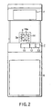
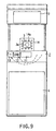
- FIG. 1 is a view schematically showing the external construction of a face image photographing system according to a first embodiment.
- the face image photographing system includes an illuminator 2 for illuminating a to-be-photographed person 1, a video camera 3 of CCD type used as photographing means for photographing at least a face image of the to-be-photographed person 1, a display (monitor display) 5 for displaying operation information of a photographer (operator) and the photographing state, a control table (control section) 6 for modifying an input image from the camera 3 or outputting the same to the display 5 or a storage section contained therein in response to an operation instruction issued by the photographer 4, a portrait-photographing device having a guidance display section 7 used as guidance means for displaying the photographing state to guide the to-be-photographed person 1, a chair 8 on which the to-be-photographed person 1 sits at the time of photographing, a background plate 9 used as a background of the to-be-
- the video camera 3 outputs a photographing image with each image constructed by 640 pixels x 480 lines. Each pixel is constructed by a color sensor of R (red), G (green), B (blue) and data (density) of each color is output for each pixel.
- the background plate 9 is formed blue, the background becomes blue when it is photographed by the video camera 3 and thus blue is used as a background color component.
- a distance from the image sensing portion of the video camera 3 to the to-be-photographed person 1 is set substantially constant.
- the photographing operation is effected by use of the video camera 3 with the photographing distance fixed.
- the guidance display section 7 includes a confirming process display portion (second display portion) 11 for displaying "wait for photographing" to the to-be-photographed person 1, an end display portion (third display portion) 12 for displaying "end of photographing" to the to-be-photographed person 1, and an exit display portion (fourth display portion) 13 for displaying "direction of traveling after the end of photographing" to the to-be-photographed person 1.
- the confirming process display portion 11 is provided in substantially the central position in the width direction of the present apparatus and in the lower portion of the camera 3 on the front side of the apparatus, the end display portion 12 is provided on the right side of the confirming process display portion 11 in the drawing and the exit display portion 13 is provided on the right side of the end display portion 12 in the drawing.
- the camera position display portion 14 has a plurality of LED display elements 14a disposed around the photographing lens 3a and they are controlled to be set into a turn-ON state, flickering state or turn-OFF state as required.
- FIG. 3 is a block diagram showing the whole construction of the face image photographing system shown in FIGS. 1 and 2 .
- the control section 6 of the face image photographing system includes a video capture section 21, video accelerator section 22, CPU section 23, external bus control section 24, large-capacity memory device 25, reader/writer section 27, I/O control section 30, network adapter (such as a LAN card) 33 and sound control section 34.
- the video capture section 21 converts an analog signal (input image) from the camera 3 into a digital signal on the real-time basis and transfers the digital signal to an MO 26 or main memory 23b used as a video memory which will be described later.
- the video accelerator section 22 stores image data from the video capture section 21 into the MO 26 or main memory 23b used as a video memory, effects the image drawing process with respect to image data from the video capture section 21 and controls the display operation of the display 5.
- the sound control section 34 controls a guidance voice to the speaker 10.
- the CPU section 23 includes a CPU (central processing unit) 23a for effecting various operating processes and various control operations with respect to image data or the like, a main memory 23b for storing image data of plural frames from the video capture section 21 in the unit of frame and temporarily storing operation results and the like and an interface (not shown) for connection with various peripheral devices.
- a CPU central processing unit
- main memory 23b for storing image data of plural frames from the video capture section 21 in the unit of frame and temporarily storing operation results and the like
- an interface (not shown) for connection with various peripheral devices.
- the CPU section 23 is connected to a keyboard 28 and mouse 29 as input devices operated by the operator (photographer) 4 via the interface.
- a photographing button 28a depressed when it is confirmed that the to-be-photographed person 1 has made preparation for photographing a photographing determination button 28b depressed when a satisfactory photographed image is obtained, and a photographing cancel button 28c depressed when re-photographing becomes necessary are provided.
- Icons for the respective photographing button 28a, photographing determination button 28b and photographing cancel button 28c are displayed on the display 5 and the same function as that obtained when one of the photographing button 28a, photographing determination button 28b and photographing cancel button 28c of the keyboard 28 is depressed can be attained by selecting one of the icons by use of a cursor moved by the mouse 29.
- the CPU section 23 is connected to an image printing device 31 used as output means, for example, for printing and outputting a photographed face image via the interface.
- the external bus control section 24 controls an external bus (such as a SCSI) for connection with various peripheral devices.
- an external bus such as a SCSI
- the large-capacity memory device 25 stores various OS, applications, control data, image data and is constructed by a hard disk device (HDD), for example.
- HDD hard disk device
- the reader/writer section (MO driver) 27 reads/writes data with respect to a portable storage medium 26 such as a magnet-optical disk for storing output data from the control table 6.
- the I/O control section 30 controls the confirming process display portion 11, end display portion 12, exit display portion 13, camera position display portion 14.
- the network adapter (such as a LAN card) 33 is used to make mutual communication with respect to other various devices (such as an image printing device and image filing device) on the same network 32.
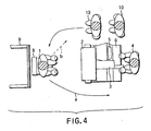
- FIG. 4 is a view for illustrating a physical flow of a photographing process between the face image photographing system, to-be-photographed person 1 and applicants 10 for photographing waiting for photographing as viewed from above.
- the to-be-photographed person 1 walks (moves) in a direction indicated by an arrow "a" of a solid line shown in FIG. 4 when the photographing operation is terminated, but if she walks in a direction indicated by an arrow "b" of broken lines, a problem occurs when a next applicant 10 for photographing takes a seat for photographing.
- the first embodiment will be described, in which the person 1 to be photographed is instructed to look at a specific point, requested to keep still, is informed that the photographing has completed, and is instructed to leave in a specific direction.
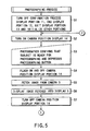
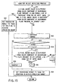
- the processing operation of the present apparatus is explained below with reference to the flowcharts shown in FIGS. 5 and 6 .
- the process explained below is mainly effected by the CPU 23a of the CPU section 23.
- step S1 the confirming process display portion 11, end display portion 12, exit display portion 13 are turned OFF, the other portions of the present apparatus are initialized and then the step S2 is effected.
- step S2 the to-be-photographed person 1 is urged to look at the photographing lens 3a of the camera 3, that is, to set the observing point at the photographing lens 3a of the camera 3 by lighting the camera position display portion 14 in red, for example.
- the photographer 4 confirms that preparation for photographing of the to-be-photographed person 1 in the step S1 is made and depresses the photographing button 28a.
- the to-be-photographed person 1 is urged to keep looking at the camera 3 by causing the camera position display portion 14 to flicker, for example, and the step S5 is effected.
- step S5 a photographed image of the to-be-photographed person 1 is fetched from the camera 3 via the video capture section 21 and temporarily stored into the main memory 23b in the CPU section 23 and the step S6 is effected.
- step S6 an input image stored in the main memory 23b in the CPU section 23 is displayed on the display 5 and the step S7 is effected.
- step S7 since the image fetching process is terminated, the camera position display portion 14 which flickers is turned OFF and the step S8 is effected.
- step S8 the confirming process display portion 11 is set into a flickering state in yellow as shown in FIG. 7 and the step S9 is effected.
- the photographer 4 determines whether or not re-photographing is necessary by checking whether the eyes are closed or not, the face position is shifted or not while observing the image displayed in the step S6. During this period, the to-be-photographed person 1 is required to wait in preparation for re-photographing. Therefore, in the step S8, the confirming process display portion 11 is set into a flickering state in yellow.
- step S9 If it is determined in the step S9 that re-photographing is necessary, the step S10 is effected and the photographer 4 depresses the photographing cancel button 28c. As a result, the process returns to the step S2 and the same operation is repeated.
- step S9 If it is determined in the step S9 that the photographed image is satisfactory, the step S1 is effected and the photographer 4 depresses the photographing determination button 28b. If the photographing determination button 28b is depressed, the step S12 is effected to turn OFF the confirming process display portion 11. Then, in the step S13, the end display portion 12 is set into a flickering state in green as shown in FIG. 8 , and at the same time, the exit display portion 13 is set into a flickering state as shown in FIG. 8 so that the to-be-photographed person 1 will be urged to walk towards the exit since the photographing is terminated.
- the input image stored in the main memory 23a in the CPU section 23 in the step S6 is converted into an image for outputting and the image is processed according to the purpose of application together with other personal information of the to-be-photographed person 1.
- the image is printed and output on a recording medium (such as paper, card) by use of the image printing device 31 connected to the CPU section 23 or an image printing device (not shown) connected to the network 32 via the network adapter 33, or stored into an image filing device (not shown) used as image storing means connected to the network 32 or stored into the large-capacity storage device 25, portable storage medium 26 or the main memory 23b in the CPU section 23 by using the same as image storing means.
- a recording medium such as paper, card
- the photographed face image may be printed or stored according to the purpose of application thereof and the outputting method of the face image can be freely selected.
- the camera position display portion 14 for displaying a position in which the to-be-photographed person looks at the camera 3 at the time of photographing by the camera 3, the confirming process display portion 11 for providing display to urge the to-be-photographed person to wait for photographing, the end display portion 12 for displaying "end of photographing" to the to-be-photographed person 1, and the exit display portion 13 for displaying the moving direction after the end of photographing to the to-be-photographed person 1 are provided, the to-be-photographed person 1 can be guided as to the photographing state by displaying the photographing state (the position in which the to-be-photographed person observes the camera 3, waiting for photographing, end of photographing, moving direction after the end of photographing) to guide the to-be-photographed person 1 and the applicants 10 for photographing making a queue will not wait for a long time. Further, by use of the above guidance display, not only a normal person but also a
- the above embodiment is not limited to the above case and can be variously modified.
- the arrangement of the end display portion 12 and exit display portion 13 can be changed according to the queue making direction of the applicants 10 for photographing and the direction to the exit for the to-be-photographed person 1.
- the moving direction of the to-be-photographed person 1 after the end of photographing is set in the left direction of this apparatus in the drawing, and in this case, the end display portion 12 is moved to the left side in a horizontal direction and set on the left side of the confirming process display portion 11 in the drawing and the exit display portion 13 is turned by 180 degrees to indicate the opposite direction and set on the left side of the end display portion 12 in the drawing.
- the position in which the to-be-photographed person 1 observes the photographing lens 3a of the camera 3 is displayed by use of the camera position display portion 14, but this is not limitative and, for example, the position can be indicated by letters "please look at the photographing lens of the camera" by use of the confirming process display portion 11 or both of them can be used.
- the second embodiment in which the size of the face of a to-be-photographed person 1 is measured and a face image of constant size is obtained by zooming the face image of the measured size.
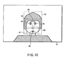
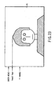
- FIG. 10 shows a case wherein an input image (face image) 41 is fetched from a camera 3, a contour area 42 of the face is detected from the input image 41 and the size of the face is measured based on the contour area 42 of the face is measured.
- the step S21 the number of retry processes counted by a counter (not shown) and other data are initialized and the step S22 is effected.
- the input image (face image of the to-be-photographed person 1) from the camera 3 is fetched via a video capture section 21 and temporarily stored into the main memory 23b of the CPU section 23 and the step S23 is effected.
- the contour area 42 of the face having a color component different from that of a background plate 9 is detected from the input image 41 stored in the main memory 23b. (The background plate 9 will be described later in detail.) The operation then goes to the step S24.
- the face size is measured by the face size (an area, a number of the pixels) measuring process which will be described later based on the face contour area 42 obtained in the step S23 and the step S25 is effected.
- the process in the step S24 corresponds to a measuring means.
- step S25 whether or not the face size measurement obtained in the step S24 lies within a specified range (i.e., area 39 that will be later described) is determined.
- the "specified range” has been derived by the reverse operation based on an input range of the zooming process which will be effected later. If the zooming ratio ranges from 0.5 to 1.5, the face size falls within the specified range when the ratio of the target size to the face size measured is 0.5 to 1.5.
- the process of the step S25 is effected by a first determining means.
- the step S26 is effected.
- the ratio of the target face size to the face size measurement is derived and the derived ratio is used as a zoom ratio.
- the target face size is an optimum face size when the face image is output as a photograph and is determined based on the average of face image data items of hundreds of people, for example.
- the process in the step S26 corresponds to zoom ratio setting means in this invention.
- the CPU 23 performs the zooming process on the input image from the camera 3 based on the zoom ratio set in the step S26 and the step S28 is effected.
- the process in the step S27 corresponds to a zoom processing means. In this example, a case wherein the zooming process is effected in an electronic manner is explained, but the zooming process may be effected according to the movement of the lens of the camera 3.
- the input image stored in the main memory 23a in the CPU section 23 is converted into an image for outputting and the image is processed according to the purpose of application together with other personal information (name, the date of birth, ID number or the like) of the to-be-photographed person 1.
- the image is printed and output on a recording medium (such as paper, card) by use of the image printing device 31 connected to the CPU section 23 or an image printing device (not shown) connected to the network 32 via the network adapter 33, or stored into an image filing device (not shown) used as image storing means connected to the network 32 or stored into the large-capacity storage device 25, portable storage medium 26 or the main memory 23b in the CPU section 23 by using the same as image storing means.
- a recording medium such as paper, card
- the photographed face image may be stored or printed on an area whose size is set to a preset size such as an identification card according to the purpose of application thereof and the outputting method of the face image can be freely selected.
- the retry process is effected. That is, first, in the step S29, the number of retry processes is incremented and the step S30 is effected. In the step S30, whether or not the number of retry processes is smaller than a specified value which is previously set is checked, and if it is smaller than the specified value, the step S31 is effected.
- the process in the steps S29, S30 corresponds to a second determining means.
- step S31 If it is detected in the step S31 that the measured face size exceeds the specified range (the face is too big), a message is displayed on the display 5 to urge the to-be-photographed person 1 to move her face farther away from the camera, and if the measured face size is too small, a message is displayed on the display 5 to urge the to-be-photographed person 1 to move her face closer to the camera, and then the process returns to the step S22 to start the process again from the step S22 as the retry process.
- step S30 If it is determined in the step S30 that the number of retry processes exceeds the specified value, it is determined that the face image will be inadequate when the face image is output as a photograph, the step S32 is effected to effect an error process and the photographing process is terminated.
- the process in the step S32 corresponds to an error processing means.
- an area 43 in which both of the pupils will exist without fail is derived as a relative positional area with respect to the face contour area 42 derived in the step S23 and portions of the same shape as the pupil, for example, black portions of round shape are extracted from the derived area 43.
- the area 43 is derived based on the average of areas in which the pupils exist without fail with respect to the face contour areas in face image data items of hundreds of people, for example.
- step S34 pupil samples previously registered are compared with the black portions of round shape extracted in the step S32 and the portions having the highest degree of similarity are extracted. Since two pupils exist, the pupil samples are prepared for right and left pupils, the above determination process is effected by comparing the extracted portions with the samples of the right and left pupils and coordinates of a left pupil portion 44 and right pupil portion 45 are derived. It is also possible to prepare pupil samples for the right or left pupil, derive the other side pupil samples by inverting or modifying the above pupil samples, for example, and thus reduce the number of prepared samples.
- the sample mentioned above has been prepared by normalizing the images of pupils of hundreds of people, for use in pattern comparison effected to determine the similarity of the pupils of the person to be photographed.
- a distance 46 between the centers of the left pupil portion 44 and the right pupil portion 45 derived in the step S33 is derived and the face size is calculated based on the derived distance 46.
- the face size is derived based on the average of face sizes with respect to the distances between the centers of the right and left pupils in face image data items of hundreds of people, for example.
- an area 43 in which both of the pupils will exist without fail is derived as a relative positional area with respect to the face contour area 42 derived in the step S23 and portions of the same shape as the pupil, for example, black portions of round shape are extracted from the derived area 43.
- step S37 pupil samples previously registered are compared with the black portions of round shape extracted in the step S36 and the portions having the highest degree of similarity are extracted. Since two pupils exist, the pupil samples are prepared for right and left pupils, the above determination process is effected by comparing the extracted portions with the samples of the right and left pupils and a left pupil portion 44 and right pupil portion 45 are derived.
- an area 47 in which a mouth will exist without fail is derived as a relative positional area with respect to the central positions of the left pupil 44 and right pupil 45 extracted in the step S37 and a portion containing reddish pixels like the mouth is extracted from the derived area 47.
- the area 47 is derived based on the average of areas containing mouths with respect to the central positions between the right and left pupils in face image data items of hundreds of people, for example.
- step S39 mouth samples previously registered are compared with the portions extracted in the step S38 and a portion having the highest degree of similarity is extracted as a mouth portion 48. Then, in the step S40, an area 49 defined by the left pupil portion 44, right pupil portion 45 extracted in the step S37 and the mouth portion 48 extracted in the step S38 is derived and the face size is derived based on the derived area 49.
- the face size is derived based on the average of face sizes with respect to the areas each defined by the right and left pupil portions and mouth portion in face image data items of hundreds of people, for example.
- the process explained below is mainly effected by the CPU 23a of the CPU section 23.
- step S41 color components of the background plate 9 are measured in a plurality of positions in the areas (searched areas) of the input image stored in the main memory 23b and then the step S42 is effected.
- step S42 whether or not the result of measurement in the step S41 indicates a color component suitable for the background plate 9 is checked and then the step S43 is effected.
- a non-bluish background (which is not a blue background) is determined as a portion of a face image of the to-be-photographed person 1.
- step S43 a head top height position detecting process, which will be described later, is effected to derive the vertical line number of the vertical head top : "head top” and then the step S44 is effected.
- step S44 whether or not the head top position lies within a specified range is checked and then the step S45 is effected.
- step S45 the central position of the face in the horizontal direction, which will be described later, is detected from the head left position and the head right position.
- the horizontal line number of the face center position : "Center" are thereby obtained.
- the step S46 is then performed.
- step S46 it is determined whether or not the face center position lies within a specified range.
- the process advances to the step S47.
- step S47 the contour 42 is detected from the head left position, head right position, head top position, and average number of lines (FACE SIZE) of the person photographed.
- step S47 the intersecting position between the horizontal line number : "Center” and the vertical line number : “head top” is set as the face contour reference position and then the step S48 is effected.
- step S48 the result of the process is set to "the face contour range is within the specified range”. The process goes to the step 24.
- the face of the person 1 is an upper part unless the person stands on his or her hands. Above the face there is located the upper part of the blue background.
- the upper and lower parts of the input image 41 are excluded from the searched area A.
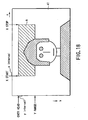
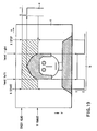
- the parameters used to exclude these parts of the image 41 from the area A will be described, with reference to FIG. 18 .
- the parameter for excluding the upper part is OVER HEAD
- the parameter for excluding the lower part is Y RANGE.
- the left and right end parts of the image 41 are excluded from the searched area A if the image 41 is a landscape one.
- the parameter for excluding the left and right end parts of the image 41 will be described, with reference to FIG. 18 , too. As shown in FIG. 18 , the parameter for excluding the left end part of the image 41 is X START, the parameter for excluding the right end part of the image 41 is X STOP.
- the image of the person 1, included in the input image 41, is almost continuous. In view of this, the following parameters are set:
- the first half of the data can be regarded as one consisting of bits arranged in the ascending order in the horizontal (X) direction.
- the other half of the data can be regarded as one consisting of bits arranged in the descending order in the horizontal (X) direction.
- the line on which the binary value changes from “0” to “1” in the Y direction is detected as the head top (the position of the head: head-top vertical line number).
- the vertical line on which the binary value changes from “0” to “1” in the X direction is detected as the left side of the head (head left).
- the vertical line on which the binary value changes from "1" to "0” in the X direction is detected as the right side of the head (head right).
- the vertical line that passes the midpoint between the vertical lines detected as the left and right sides of the head is detected as one that passes the center of the face.
- Any line on which the binary value changes can be detected by searching the area A, from one side thereof.
- the area A may be divided into two halves, and these halves may be searched at the same time, because the data, which is searched for, consists of bits arranged in the ascending (or descending) order of the binary value. In this case, the line can be detected with higher efficiency.
- the face contour area 42 is detected from the left side of the head (head left), the right side of the head (head right), the top of the head (head top), and the FACE SIZE (i.e., the average number of lines of the face length of people), as is illustrated in FIG. 21 .
- the specified range of the face contour area 42 is determined based on the values of the horizontal line number : "Center” and the vertical line number : "head top” for defining the face contour reference position and is a range from which the trimming size can be acquired as a photograph size with the face set at the center and it can be expressed as follows.
- the center of the face exists in an area the left side of which is half the framing area (trimming area) X FMG SIZE from the left side of the input image 41 and the right side of which is half the difference between the line number X STILL SIZE and the framing area X FMG SIZE from the right side of the input image 41.
- the top of the head exists in an area the upper side of which is the line number OVER HEAD from the upper side of the input image 41 and the lower side of which is the difference between the line number Y STILL SIZE and the framing area Y FMG SIZE from the lower side of the input image 41.
- fmg-x and fmg-y are the X-ordinate Y-ordinate of the upper-left trimming corner of the input image 41, respectively.
- the head top portion of the to-be-photographed person 1 lies within the specified range ("OVER HEAD + 1 line” to "Y RANGE line") in which at least the head top portion of the to-be-photographed person 1 may exist.
- the number of pixels that is, the face portion of the to-be-photographed person 1 whose color is different from the color component of the background plate 9 among the pixels constituting the horizontal line of the vertical line number : "OVER HEAD" of the input image is counted and whether or not the counted number is larger than a specified value is checked.
- the specified value is set to such a numerical value that an unusual portion can be neglected in a case where the to-be-photographed person 1 has her hair disordered in the horizontal direction or a foreign matter whose color is different from the color of the background plate 9 is attached thereto.
- the vertical line number : "OVER HEAD” in the input image is set to i, "Y RANGE” is set to j and then the step S52 is effected.
- step S52 "OVER HEAD” is set to i, "Y RANGE” is set to j and the step S53 is effected.
- step S54 is effected.
- the central line (i+j)/2 between the i line and the j line is set to k and then the step S55 is effected.
- the number of pixels whose color is different from the color component of the background plate 9 among the pixels constituting the kth horizontal line is counted and whether or not the counted number is equal to or larger than a specified value is determined.
- the specified value is set to such a numerical value that an unusual portion can be neglected in a case where the to-be-photographed person 1 has her hair disordered in the horizontal direction or a foreign matter whose color is different from the color of the background plate 9 is attached thereto.
- step S55 If the result of determination in the step S55 is "YES”, k is set to j in the step S56 and the process returns to the step S53. If the result of determination in the step S55 is "NO”, k is set to i in the step S57 and the process returns to the step S53.
- the searching area is halved for each processing loop starting from a searching area from the "OVER HEAD" of the input image to "Y RANGE” and then the step S58 is effected when (j-i) becomes smaller than 1 (when the difference in line number decreases to zero). That is, when the result of the determination in the step S53 is "NO", the process goes to the step S58.
- step S58 i of the head-top X line (X coordinate) at the left end of the face is set to "head top” and the step S59 is effected.
- step S59 the head top position is set within the specified range as the result of the process. The process goes to the step S44.
- step S60 is effected.
- the head top position is set outside the specified range as the result of the process. The process goes to the step S44.
- the vertical line number "0" at the left end of the input image is set to i
- the vertical line number (X STILL SIZE/2) at the center of the input image is set to j and then the step S62 is effected.
- the step S62 whether or not at least one line exists between the i line and the j line is determined, and if the result of determination is "YES", the step S63 is effected.
- the vertical line (i+j)/2 at the center between the i line and the j line is set to k and then the step S64 is effected.
- the step S64 the number of pixels whose color is different from the color component of the background plate 9 measured in the step S41 among the pixels constituting the kth vertical line is counted and whether or not the counted value is equal to or larger than a specified value is determined.
- the specified value is set to such a numerical value that an unusual portion can be neglected in a case where the to-be-photographed person 1 has her hair disordered in the horizontal direction or a fine foreign matter whose color is different from the color of the background plate 9 is attached thereto.
- step S64 If the result of determination in the step S64 is "YES”, k is set to j in the step S65 and the process returns to the step S62. If the result of determination in the step S64 is "NO”, k is set to i in the step S66 and the process returns to the step S62.
- the searching area is halved for each processing loop starting from a searching area of the left half of the input image and then the step S67 is effected when (j-i) becomes smaller than 1, that is, when the result of determination in the step S62 is "NO".
- step S67 i is set to the vertical line at the left end of the face : "head left" when it is determined in the step S62 that (j-i) becomes smaller than 1 and the step S68 is effected.
- step S68 the vertical line number at the center of the input image ((X START + X STOP)/2) shown in FIG. 25 is set to i, the vertical line number at the right end of the input image (X STOP) is set to j and the step S69 is effected.
- step S69 whether or not at least one line exists between the i line and the j line is determined, and if the result of determination is "NO", the step S70 is effected.
- the vertical line (i+j)/2 at the center between the i line and the j line is set to k and then the step S71 is effected.
- the step S71 the number of pixels whose color is different from the color component of the background plate 9 measured in the step S41 among the pixels constituting the kth vertical line is counted and whether or not the counted value is equal to or larger than a specified value is determined.
- the specified value is set to such a numerical value that an unusual portion can be neglected in a case where the to-be-photographed person 1 has her hair disordered in the horizontal direction or a fine foreign matter whose color is different from the color of the background plate 9 is attached thereto.
- step S71 If the result of determination in the step S71 is "YES”, k is set to i in the step S72 and the process returns to the step S69. If the result of determination in the step S71 is "NO”, k is set to j in the step S73 and the process returns to the step S69.
- the searching area is halved for each processing loop starting from a searching area of the right half of the input image and then the step S74 is effected when (j-i) becomes smaller than 1, that is, when the result of determination in the step S69 is "YES".
- step S74 i is set to the vertical line at the right end of the face : "head right" when it is determined in the step S69 that (j-i) becomes smaller than 1 and the step S75 is effected.
- step S75 as shown in FIG. 26 , the central position is derived based on "head left” set in the step S67 and "head right” set in the step S74, the derived value is set as a value of "center”. The process goes to the step 46.
- the face contour area 42 containing the hair style of the to-be-photographed person 1 detected in the step S23 is determined by the contour reference position ("center", “head top") of the face, "head left”: the left side position of the head, "head right”: the right side position of the head, "FACE SIZE” : the average number of lines of the longitudinal lengths of the faces of a plurality of to-be-photographed persons 1.
- an area defined as shown in FIG. 27 by an x-coordinate : "x eye area posi” and y-coordinate : “y eye area posi” which indicate the left top point, the size in the horizontal direction : “X EYE AREA SISE” and the size in the vertical direction : “Y EYE AREA SIZE” based on the contour reference position ("center", "head top") of the face is derived.
- the x-coordinate : "x eye area posi" and y-coordinate : "y eye area posi” are expressed by the following equations.
- x eye area posi head top + Y EYE POSI SIZE - Y EYE AREA SIZE / 2
- y eye area posi head top + Y EYE POSI SIZE - Y EYE AREA SIZE / 2
- the X-direction ordinate (x eye area posi) of the left side of the face contour area 42 is obtained by subtracting half the width (the line number: X EYE AREA SIZE) of the area 42, which is a known value, from the center (i.e., the X-direction ordinate of the face contour reference position).
- the Y-direction ordinate (y eye area posi) of the upper side of the face contour area 42 is obtained by adding the average number of lines (Y EYE POSI SIZE), existing between the top of the head and the pupils, to the head top (i.e., the Y-direction ordinate of the face contour reference position) and by subtracting, from the sum, half the height of the area 43 (i.e., the line number: Y EYE AREA SIZE), which is a known value.
- the photographer determines whether the face of a person to be photographed is larger or smaller than the standard size. If the face is larger or smaller than the standard size, the photographer performs zooming, adjusting the image of that person's face to the standard size.
- the photographing cycle is as short as few seconds, it would be hard for the photographer to adjust the size of the image of the face within such a short time. He or she may likely make an error in determining the size of the face image in comparison with the standard size.
- the above-described second embodiment is free of the problems inherent in the conventional face image photographing apparatus.
- the second embodiment determines the size of the face image included in the input image of the person 1 and automatically performs zooming, if necessary, to adjust the size of the face image to the standard size.
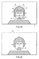
- FIGS. 28 and 29 show an input image (face image) from a camera 3 and areas and coordinates used in processes effected in the photographing process.
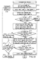
- the processing operation of the present apparatus is explained with reference to FIGS. 28 and 29 arid the flowchart of FIG. 30 .
- the process explained below is mainly effected by the CPU 23a of the CPU section 23.
- step S81 the number of retry processes counted by a counter (not shown) and other data are initialized and the step S82 is effected.
- step S82 an input image 41 from the camera 3 is fetched via a video capture section 21 and temporarily stored into the main memory 23b of the CPU section 23 and the step S83 is effected.
- the detecting process for detecting whether the to-be-photographed person 1 exists in front of the camera 3 is effected based on the input image 41 in the main memory 23b. That is, for example, whether the to-be-photographed person 1 exists or not and whether or not the position of a face contour area 42 containing the hair style of the to-be-photographed person 1 is set within an adequate range for outputting are determined by searching for an area (that is, an area of the to-be-photographed person 1) having pixels whose color is different from the background color in the input image 41.
- the process of the steps S83, S84 corresponds to a to-be-photographed person detecting means.
- the process returns to the step S82 and the above-described operation is repeated. If the to-be-photographed . person 1 exists in front of the camera 3 and the position of the face contour area 42 lies in an adequate range, the step S85 is effected. In the step S85, a guidance message is output by use of a display 5 and speaker 10 to urge the to-be-photographed person 1 in front of the camera 3 to make preparation for photographing and then the step S86 is effected.
- the process of the step S85 corresponds to a photographing guiding means.
- step S86 after the image 41 is input, a stand-by state is maintained for a specified period of time which is required for determining whether or not the to-be-photographed person 1 stands still (makes preparation for photographing) in a process for determining the photographing possible state which will be described later and then the step S87 is effected.
- step S87 an input image 41' which follows the input image 41 is fetched from the camera 3 and temporarily stored into the main memory 23b of the CPU section 23 and the step S88 is effected.
- steps S88, S89 whether or not the to-be-photographed person 1 can make preparation for photographing is determined by effecting the photographing possible state determining process by use of the input images 41 and 41' in the main memory 23b.
- the detail of the photographing possible state determining process is explained later.
- the process of the steps S88, S89 corresponds to a recognizing means.
- the step S90 is effected to select one of the input images 41 and 41' which is suitable for outputting of the face image and stored in the main memory 23b of the CPU section 23 and for converting the selected image into an image for outputting.
- the thus obtained image is processed according to the purpose of application together with other personal information of the to-be-photographed person 1.
- the image is printed and output on a recording medium (such as paper, card) by use of an image printing device 31 connected to the CPU section 23 or an image printing device (not shown) connected to a network 32 via a network adapter 33, or output and stored into an image filing device (not shown) used as image storing means connected to the network 32 or stored into a large-capacity storage device 25, portable storage medium 26 or the main memory 23b in the CPU section 23 by using them as image storing means.
- a recording medium such as paper, card
- the photographed face image may be printed or stored according to the purpose of application thereof and the outputting method of the face image can be freely selected.
- the step S91 is effected and the retry process is effected.
- the number of retry processes is incremented and then the step S92 is effected.
- the step S92 whether or not the number of retry processes is less than a specified value previously set is determined and if it is less than the specified value, the process returns to the step S82 and the process starting from the step S82 is effected as the retry process again.
- the process of the steps S91, S92 corresponds to a determining means.
- step S92 If the result of determination in the step S92 indicates that the number of retry processes exceeds the specified value, it is determined that the image will be an inadequate image when it is output as an output photograph, the step S93 is effected to effect the error process and the photographing process is terminated.
- the process of the step S93 corresponds to an error processing means.
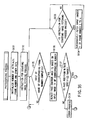
- an area 43 in which both of the pupils will exist without fail is derived as a relative positional area with respect to a face contour area 42 and portions of the same shape as the pupils, for example, black portions of round shape are extracted from the derived area 43.
- the area 43 is derived from the average of areas in which both of the pupils exist without fail in face contours in face image data items of hundreds of people, for example.
- step S102 pupil samples previously registered are compared with the black portions of round shape extracted in the step S101 and the portions having the highest degree of similarity among those which have degrees of similarity larger than a specified value are extracted. Since two pupils exist, the pupil samples are prepared for right and left pupils, the above determination process is effected by comparing the extracted portions with the samples of the right and left pupils and a left pupil portion 44 and right pupil portion 45 are derived.
- an area 47 in which a mouth will exist without fail is derived as a relative positional area with respect to the central positions of the left pupil 44 and right pupil 45 extracted in the step S102 and a portion containing reddish pixels like the mouth is extracted from the derived area 47.
- the area 47 is derived from the average of areas containing mouths with respect to the central positions between the right and left pupils in face image data items of hundreds of people, for example.
- step S104 mouth samples previously registered are compared with the portions extracted in the step S103 and a portion having the highest degree of similarity among those which have degrees of similarity larger than a specified value is extracted as a coordinate 48 of a mouth portion.
- step S105 the absolute values of luminance differences between pixels in a specified peripheral area 50 on the left pupil coordinate 44 in the input image 41 of FIG. 28 and an area 52 of the same size on the same coordinate in the input image 41' of FIG. 29 are derived and the total sum SumDef1 in the whole portion of the area is derived.
- the absolute values of luminance differences between pixels in a specified peripheral area 51 on the right pupil coordinate 45 in the input image 41 of FIG. 28 and an area 53 of the same size on the same coordinate in the input image 41' of FIG. 29 are derived and the total sum SumDef2 in the whole portion of the area is derived.
- the absolute values of luminance differences between pixels in a specified peripheral area 53 on the mouth portion coordinate 48 in the input image 41 of FIG. 28 and an area 54 of the same size on the same coordinate in the input image 41' of FIG. 29 are derived and the total sum SumDef3 in the whole portion of the area is derived.
- the total values SumDef 1, SumDef2, SumDef3 of the luminance difference absolute values derived in the steps S105 to S107 are compared with specified values respectively set therefor and whether or not they are all equal to or smaller than the respective specified values is determined. If the result of the above determination indicates that all of the three numerical values are equal to or smaller than the respective specified values, it is determined that the photographing possible state is set up, and if at least one of the three numerical values exceeds the corresponding specified value, it is determined that the photographing possible state is not set.
- the above three numerical values are less than the respective specified values.
- the above three numerical values are greater than the respective specified values. If the person blinks, the numerical values SumDef2, SumDef3 are greater than the corresponding specified values. If the to-be-photographed person speaks or the mouth moves, the numerical value SumDef3 is greater than the corresponding specified value.
- the specified period of time in the step S86 is movement monitoring time required for the above three numerical values to be numerically expressed when the to-be-photographed person 1 cannot prepare for photographing and some movement occurs.
- the photographer determines whether or not the person to be photographed is in a condition to be photographed. If the photographer determines that the person is ready to be photographed, he or she starts photographing that person.
- the photographing cycle is as short as a few seconds, however, it would be difficult for the photographer to look at the person while operating the apparatus to determine within such a short time whether or not the person is ready to be photographed. He or she may likely make an error in determining if the person can be photographed.
- the above-described third embodiment is free of the problems inherent in the conventional face image photographing apparatus.
- the third embodiment determines whether or not the person is ready to be photographed, by continuously monitoring the eyes and mouth in a plurality of images obtained by continuously photographing the person. That is, whether the person can be photographed is automatically determined, not by a photographer.
- a fourth embodiment which substantially corresponds with the present invention.
- the present embodiment relates to a process effected after the photographing operation.
- the process for deriving the face contour area explained in the second embodiment is also effected.
- FIG. 32 shows a state in which an input image (face image) 61 from a camera 3 and an approximate positional area 63 of pupils (eyes) which will lie in a relative position with respect to a contour position 62 of a face in the input image 61 are specified and positional areas 64, 65 of both pupils are extracted from the approximate positional area 63.
- the processing operation of the present apparatus is explained with reference to FIG. 32 and the flowchart of FIG. 33 .
- the process explained below is mainly effected by the CPU 23a of the CPU section 23.
- step S111 the number of retry processes and other data are initialized and the step S112 is effected.
- step S112 an input image (face image) 61 from the camera 3 is fetched via a video capture section 21 and temporarily stored into a main memory 23b of the CPU section 23 and the step S113 is effected.
- step S113 the face contour area 62 containing the hair style is detected in the input image 61 in the main memory 23b and then the step S114 is effected.
- step S114 whether or not the detected face contour position 62 lies within a preset specified range is checked and if it lies outside the specified range, the step S115 is effected to effect the error process and the state is returned to the initialized state.
- the step S116 is effected.
- the approximate positional area 63 of pupils (eyes) which lie in a relative position with respect to the face contour position 62 is derived and the positional areas (64, 65) having the same round form as the pupils are extracted from the approximate positional area 63 and then the step S117 is effected.
- the approximate positional area 63 is derived based on the average of areas in which both of the pupils exist without fail with respect to the face contour areas in face image data items of hundreds of people, for example.
- step S117 whether or not the number of extracted positional areas of round form is equal to or larger than a preset specified value (two) is checked and if the number is smaller than the specified value, it is determined that the pupil is not normally opened and the step S118 is effected.
- step S118 a standby state is maintained for a preset specified period of time (approx. 0.1 second) and then the step S119 is effected.
- step S119 whether or not the number of retry processes is smaller than a preset specified value is checked and if it is smaller than the specified value, the step S120 is effected.
- the step S120 the number of retry processes is incremented and the process returns to the step S112. That is, if the number of retry processes is smaller than the specified value, a standby state is maintained for a specified period of time (approx. 0.1 second) and then the process returns to the step S112 to input a face image as the retry process again.
- step S121 is effected to effect the error process and the state is returned to the initialized state.
- step S117 If it is determined in the step S117 that the number of positional areas is not smaller than the specified value, it is determined that the pupils are normally opened and the step S122 is effected.
- step S122 the shapes of the peripheral portions of the extracted positional areas 64, 65 are compared with sample data items of the pupils stored in the main memory 23b in the CPU section 23 to extract the extracted portions having the highest degree of similarity for the right and left pupils and then the step S123 is effected.
- step S123 whether or not the degree of similarity of the portion having the highest degree of similarity and extracted in the step S122 is higher than a preset threshold value is checked and if it is smaller than the preset threshold value, the step S119 is effected and the retry process which is the same as described before is effected. If it is detected in the step S123 that it is larger than the threshold value, it is determined that the pupils are normally opened and the step S124 is effected.
- the input image fetched or obtained in the step S112 is converted into an image for outputting and processed according to the purpose of application together with other personal information of the to-be-photographed person 1.
- the image is printed and output on a recording medium (such as paper, card) by use of an image printing device 31 connected to the CPU section 23 or an image printing device (not shown) connected to a network 32 via a network adapter 33, or stored into an image filing device (not shown) used as image storing means connected to the network 32 or stored into a large-capacity storage device 25, portable storage medium 26 or the main memory 23b in the CPU section 23 by using them as image storing means.
- a recording medium such as paper, card
- the face image may be printed or stored according to the purpose of application thereof and the outputting method of the face image can be freely selected.
- the process of the steps S122, S123 is effected as a correction process for erroneous determination made in the process of the steps S116, S117.
- the process of the steps S122, S123 is effected for unusually opened pupils (surprisingly big round eyes) which cannot be determined in the process of the steps S116, S117 to effect the retry process.
- the photographer examines the image to see if the person's pupils were opened or the person blinked at the moment of photographing. If the image is found to be an undesirable one, the photographer has to repeat the photographing process.
- the photographing cycle is as short as few seconds, however, it would be difficult for the photographer to examine the image within such a short time. He or she may likely make an error in examining the image.
- the above-described fourth embodiment is free of the problems inherent in the conventional face image photographing apparatus.
- the fourth embodiment determines whether or not the image is an undesirable one because, for example, the person blinked when photographed, and automatically discards any image found to be undesirable.
- the fourth embodiment outputs the best possible images.
- FIG. 34 shows a state in which an input image (face image) 71 from a camera 3 and an approximate positional area 73 of pupils (eyes) which lie in relative positions with respect to a face contour position 72 in the input image 71 are specified, positional areas 74, 75 of the pupils are extracted from the approximate positional area 73, and an image cut-out area 77 is determined based on the relative position with respect to a central position (coordinates) 76 of the positional areas 74, 75 of the pupils.
- the processing operation of the present apparatus is explained with reference to FIG. 34 and the flowcharts of FIGS. 35 and 36 .
- the process explained below is mainly effected under control of the CPU 23a of the CPU section 23.
- a photographer (operator) 4 waits for a to-be-photographed person 1 to make preparation for photographing and then the photographing process of the present apparatus is started by depressing a photographing button 28a on a keyboard 28 when the to-be-photographed person 1 has made preparation for photographing.
- step S132 a start instruction for the image fetching process is issued and the steps S133, S135 are effected.
- the step S133 it is confirmed that the startle instruction for the image fetching process is issued and the step S134 is effected.
- step S134 input images (face images) 71 with the frame number "0" to “n” are successively fetched from the camera 3 via a video capture section 21 and temporarily stored as successive images (moving picture) of a plurality of frames into a main memory 23b used as a work memory in the CPU section 23.
- the image fetching process is effected while the image fetching process starting instruction is being issued. That is, issuance of the image fetching process starting instruction is interrupted when the images of the frame number "0" to "n” are fetched.
- step S135 a standby state is maintained until fetching of an image of a corresponding frame number (for example, the frame number "0" which is initially set in the step S131) is completed in parallel to the process of the steps S133, S134 and when the image fetching process is completed, the step S136 is effected.
- step S136 a face contour position 72 containing the hair style is detected in the input image 71 of the frame number "0" stored in the main memory 23b of the CPU section 23 and the step S137 is effected.
- step S137 whether or not the detected face contour position 72 is within a preset specified range is checked and if it is outside the specified range, the step S138 is effected to effect the error process and the state is returned to the initialized state. If it is within the specified range, the step S139 is effected.
- step S139 an approximate positional area 73 of pupils (eyes) which lie in relative positions with respect to the face contour position 72 is specified, positional areas 74, 75 having the same round form as the pupils are extracted from the approximate positional area 73 and the step S140 is effected.
- the area 73 is derived based on the average of areas in which both of the pupils exist without fail with respect to the face contour areas in face image data items of hundreds of people, for example.
- step S140 whether or not the images (pupils) of the extracted positional areas 74, 75 of round form are suitable for printing and outputting is checked and if the images are not suitable for printing and outputting because of the blinked or closed eyes, the step S141 is effected.
- step S141 whether or not the number of retry processes is smaller than a preset specified value is checked and if it is smaller than the specified value, the step S142 is effected.
- step S142 the number of retry processes and the frame number are incremented and the process returns to the step S135. That is, if the number of retry processes is smaller than the specified value, the process returns to the step S135 and the retry process is effected for an image with the next frame number "1".
- step S141 If it is detected in the step S141 that the number of retry processes is larger than the specified value, the step S143 is effected to effect the error process and the state is returned to the initialized state.
- step S144 If it is detected in the step S140 that the image contains no blinked or closed eyes and is suitable for printing and outputting, the step S144 is effected.
- a central position (coordinate) 76 between the positional areas 74 and 75 is derived based on the positional areas 75, 76 of the pupils extracted in the step S139, an image cut-out area 77 is determined based on the relative position with respect to the central position 76, an image in the image cut-out area 77 is cut out from the input image and the step S145 is effected.
- the area 77 is derived based on the average of image cut-out areas with respect to the central positions of the right and left pupil portions in face image data items of hundreds of people, for example.
- the image cut out in the step S144 is processed according to the purpose of application together with other personal information of the to-be-photographed person 1.
- the image is printed and output on a recording medium (such as paper, card) by use of a printing section (not shown) connected to a network 32 via a LAN card 33, or output to a storage device such as an image filing device (not shown) connected to the network 32 or stored into a large-capacity storage device 25 such as an HDD, portable storage medium 26 or the main memory 23b in the CPU section 23 and then the step S146 is effected.
- the standby state is maintained until the image fetching process of the frame number "n" is terminated and then the step S147 is effected when the image fetching process is terminated.
- step S147 the successive images of n frames temporarily stored in the main memory 23b of the CPU section 23 are stored as backup images into the large-capacity storage medium 25 and the process is terminated.
- step S145 if the photographer 4 determines that the image is not adequate as a certificate photograph because the to-be-photographed person 1 opens the mouth or looks the other way or the erroneous determination is made in the process of the steps S139, S140, the photographer selects an adequate one of the successive images of n frames backed up and outputs the selected image.
- the process is explained in detail below with reference to the flowchart of FIG. 37 .
- the photographer 4 inputs an inquiry number of re-output objects registered at the time of photographing via a keyboard 28 to effect the step S152 and search for backup images corresponding to the inquiry number in the large-capacity storage medium 25.
- the searching process if it is detected that no corresponding images are present (S153), the step S154 is effected to display a message indicating that the image corresponding to the inquiry number is not present on the display 5 and the process is terminated.
- step S155 is effected to read out all of the corresponding backup images and display them on the display 5 and then the step S156 is effected.
- step S156 the photographer selects an image suitable for a certificate photograph from the images of all of the frames displayed on the display 5, then the frame number thereof is input via the keyboard 28 and the step S157 is effected.
- step S157 an image corresponding to the frame number input via the keyboard 28 is searched for in and read out from the large-capacity storage medium 25, the thus readout image is subjected to the same process as the step S15 and printed and output and then the re-output process is terminated.
- the photographer examines the image to determine whether it is a desirable one or not. If the image is found to be an undesirable one because, for example, it shows the person blinking, the photographer has to repeat the photographing process.
- the photographing cycle is as short as few seconds, however, it would be difficult for the photographer to examine the image within such a short time. He or she may likely make an error in examining the image.
- the above-described fifth embodiment is free of the problems inherent in the conventional face image photographing apparatus.
- the fifth embodiment determines whether or not the image is an undesirable one because, for example, the person blinked when photographed. It automatically discards any image found to be undesirable and, therefore, always outputs good images.
- the re-output process program has been explained based on the assumption that it is provided in the present apparatus, but, it is also possible to provide the same in a terminal device exclusively used for the re-output process and connected to the network 32 via the network adapter 33 and the present apparatus.
- the successive images of n frames stored or backed up in the large-capacity storage medium 25 are erased when information of completion of issuance is acquired from a certificate photograph issuing management system separately installed on the networks for example.
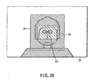
- FIG. 38 shows a state in which an input image (face image) 81 from a camera 3 and an area 82 in which pupils will exist while the coordinate of the glabella 83 set as the center of the face in the input image 81 is set as a reference are extracted and an image area 84 of the output photograph size is extracted.
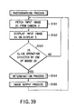
- the processing operation of the present apparatus is explained with reference to FIG. 38 and the flowcharts of FIGS. 39 , 40 and 41 .
- the process explained below is mainly effected by the CPU 23a of the CPU section 23.
- an input image (face image) 81 is fetched from a camera 3 via a video capture section 21 and the step S162 is effected.
- the input image 81 is displayed on a display 5 via a video accelerator section 122 and the step S163 is effected.
- the step S163 whether or not a click operation is effected by use of a mouse 29 is checked, and if it is determined that no click operation is effected, the process returns to the process S161. That is, if the click operation is not effected, the input image is displayed on the display 5 in a state similar to the display state of a moving picture.
- step S163 If it is determined in the step S163 that the click operation is effected, a determination process (S164) which will be explained with reference to FIG. 40 and an image outputting process (S165) which will be explained with reference to FIG. 41 are effected and then the process returns to the process S161.
- the step S164 is a process for determining whether or not the image contains a closed-eye image when the click operation is effected by use of the mouse 29 and is explained below with reference to FIG. 40 .
- the step S171 the number of retry processes and other data items are initialized and the step S172 is effected.
- the input image 81 fetched from the camera 3 is temporarily stored into a main memory 23b of a CPU section 23 (in a position of a buffer number corresponding to the number of retry processes) and then the step S173 is effected.
- an area 82 in which the pupils will exist is derived while a coordinate 83 of the glabella which is clicked on the image in the Nth image buffer by use of the mouse 29 is used as a reference and then the step S174 is effected.
- the approximate positional area 82 of the pupils (eyes) which lie in relative positions with respect to the coordinate 83 of the position of the glabella is derived based on the coordinate 83 of the glabella.
- positional areas (84, 85) having the same round form as the pupils are extracted from the area 82 and the step S175 is effected.
- the area 82 is derived based on the average of areas in which the pupils exist without fail with respect to the coordinate of the position of the glabella in face image data items of hundreds of people, for example.
- step S175 whether or not the number of extracted positional areas of round form is equal to or larger than a preset specified value (two) is checked, and if it is smaller than the specified value, it is determined that the pupils are not normally opened (the to-be-photographed person 1 blinked or closed her eyes when she was photographed) and the step S176 is effected.
- step S176 whether or not the number of retry processes is smaller than a preset specified value is checked , and if it is smaller than the specified value, the step S177 is effected.
- step S177 a standby state is maintained for a preset specified period of time (approx. 0.1 second) and then the step S178 is effected.
- step S178 the number of retry processes is incremented and the process returns to the step S172. That is, if the number of retry processes is smaller than the specified number of times, the standby state is maintained for the specified period of time (approx. 0.1 second) and then the step S172 is effected again to input a face image as the retry process.
- step S177 If the to-be-photographed person does not normally open her eyes, for example, if she opens her eyes but looks aside or does not directly look at the camera, this state is determined in the step S177 and the CPU waits for her to normally open her eyes. Further, the process of the step S177 is effected as a correction process for erroneous determination made in the process of the step S175.
- the process of the step S177 is effected for unusually opened pupils (surprisingly big round eyes) which cannot be determined in the process of the step S175 to effect the retry process.
- step S176 If it is detected in the step S176 that the number of retry processes is larger than the specified value, the step S177 is effected to effect the error process and the state is returned to the initialized state.
- step S175 If it is detected in the step S175 that the number of extracted portions is equal to or larger than the specified value, it is determined that the pupils are normally opened and the step S178 is effected.
- step S178 the forms of the peripheral portions of the positional areas 84, 85 are compared with sample data of pupils previously stored in the Nth image buffer of the main memory 23b of the CPU section 23 and the extracted portions having the highest degree of similarity are extracted for the right and left pupils and then the step S179 is effected.
- step S179 whether or not the degree of similarity of the extracted portion detected to have the highest degree of similarity in the step S178 is larger than a preset threshold value is checked, and if it is smaller than the threshold value, the step S176 is effected to effect the retry process which is the same as described before.
- the step S176 is effected to effect the retry process which is the same as described before.
- the above determination process is effected by comparing the extracted portions with the sample data items of the right and left pupils to recognize the states of the right and left pupils.
- step S181 whether or not an error is present in the result of the determination process effected in an immediately preceding cycle is determined. If it is detected that an error is present in the result of the determination process, the buffer number is set to "0", that is, the image buffer in which an image closest to the timing of clicking for photographing is recorded is selected (step S182) and the step S183 is effected.
- the image buffer of the buffer number now registered is selected and the step S183 is effected.
- step S183 an image area 84 of output size is cut out from an image of the image buffer selected in the step S181 or S182 with the clicked coordinate set as a reference and the step S184 is effected.
- the cut-out image is subjected to the compression process if necessary, stored into a large-capacity storage medium 25 or portable storage medium 26, or output to a printer (not shown) or filing device (not shown) on a network 32 via a network adapter 33.
- the mouse is used as a pointing device, but a method using a touch panel for directly clicking the screen may be used.
- the photographing button is depressed, an image covering a large area and including the image of the face is input, the data representing the image is stored into a storage medium, the image is trimmed to remove parts around the face, and the image thus trimmed is output.
- This sequence of processes is long and complex. Inevitably, it takes much time to output the image after the photographing button is pushed.
- the sixth embodiment it is not necessary to perform the complicated process of trimming the photographed image. From the image displayed on a screen it is determined whether or not the image is a desirable one or not. The sixth embodiment automatically discards any image found to be undesirable and, thus, always outputs good images.
- photographed image data is monitored and displayed and when an instruction for fetching the image is issued based on the monitored and displayed image, the image monitored and displayed immediately before issuance of the instruction is selected is explained as a seventh embodiment.
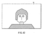
- FIG. 42 shows an input image (face image) 91 from a camera 3.
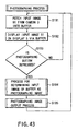
- the processing operation of the present apparatus will be explained with reference to FIG. 42 and the flowchart of FIG. 43 .
- the process explained below is mainly effected by the CPU 23a of the CPU section 23.
- the input image (face image) 91 is fetched from the camera 3 via a video capture section 21, the input image 91 is supplied to and stored in a buffer section of the main memory 23b of the CPU section 23 via a video accelerator 22 and the step S192 is effected.
- the input image 91 is displayed on a display 5 and the step S193 is effected.
- whether or not the photographing button 28a of the keyboard 28 is depressed is checked, and if it is determined that the photographing button 28a is not depressed, the process returns to the process S191.
- the photographing button 28a is not depressed, the input image is displayed on the display 5 in a state similar to the display state of a moving picture In this case, images obtained before the present photographing image are recorded in the buffer section of the main memory 23a.
- an image stored in the buffer section and displayed on the display 5 when the photographing button 28a is depressed is determined as a photographing image (step S194).
- the image determined as the photographing image is stored into a large-capacity storage medium 25 or portable storage medium 26, or output to a printer (not shown) or filing device (not shown) on a network 32 via a network adapter 33 (step S195).
- the photographer sees the image being monitored and pushes the photographing button if he or she determines that the image is a desirable one.
- the image input at the very time the photographing button is pushed is output as a photograph. Since it takes some time until the button is fully depressed to input the image, the image input is inevitably different from the image that the photographer has found a desirable one. Hence, the image input may not be a desirable one. If this is the case, the photographer needs to repeat the photographing process.
- the seventh embodiment described above is free of the problem inherent to the conventional face image photographing apparatus. This is because, when an instruction for fetching an image is generated, the image displayed immediately before the generating of the instruction is selected and output. Hence, the seventh embodiment always outputs good images.
Claims (8)
- Verfahren zum Fotografieren eines Gesichtbildes mit den Schritten:Fotografieren mindestens eines Gesichtsbildes einer Person (1),Detektieren der Position der Pupillen basierend auf dem fotografierten Gesichtsbild, undErkennen des Zustands der Pupillen basierend auf dem fotografierten Gesichtsbild zum Bestimmen, ob die Pupillen auf normale Art geöffnet sind,gekennzeichnet durchMessen der Größe des Gesichts der Person basierend mindestens auf der Beziehung zwischen den detektierten Pupillenpositionen,Erhalten eines Gesichtbildes konstanter Größe durch Unterwerfen des fotografierten Gesichtsbildes einem Zoom-Prozess gemäß der gemessenen Gesichtsgröße, undWiederholen der Schritte des Fotografierens, Detektierens und Erkennens, wenn im Schritt des Erkennens bestimmt wird, dass mindestens eine der Pupillen nicht auf normale Art geöffnet ist.
- Verfahren zum Fotografieren eines Gesichtsbildes nach Anspruch 1, ferner mit dem Schritt:Ausgeben des fotografierten Gesichtsbildes als ein fotografiertes Gesichtsbild oder als ein gedrucktes Bild oder an ein Bildspeichermedium, wenn im Schritt des Erkennens bestimmt wird, dass die Pupillen auf normale Art geöffnet sind.
- Gesichtsbildfotografiervorrichtung mit
einem Fotografiermittel (3) zum Fotografieren mindestens eines Gesichtsbildes einer Person (1),
einem Detektionsmittel (23a, 23b) zum Detektieren der Position der Pupillen basierend auf dem von dem Fotografiermitteln (3) fotografierten Gesichtsbild, und
Bestimmungsmittel (23a, 23b) zum Erkennen des Zustands der Pupillen basierend auf dem fotografierten Gesichtsbild zum Bestimmen, ob die Pupillen auf normale Art geöffnet sind,
gekennzeichnet durch
ein Messmittel (23) zum Messen der Größe des Gesichts der Person basierend mindestens auf dem Verhältnis zwischen den detektierten Pupillenpositionen,
ein Zoom-Verarbeitungsmittel (23) zum Unterwerfen des fotografierten Gesichtsbildes einem Zoom-Prozess gemäß der gemessenen Gesichtsgröße, um ein Gesichtsbild konstanter Größe zu erhalten, und
ein Wiederholsteuermittel (23a, 23b) zum Veranlassen, dass der Gesichtsbildfotografierprozess von dem Fotografiermittel (3), der Pupillenpositionsdetektionsprozess von dem Detektionsmittel (23a, 23b) und der Pupillenzustandsbestimmungsprozess von dem Bestimmungsmittel (23a, 23b) erneut ausgeführt wird, wenn von dem Bestimmungsmittel (23a, 23b) bestimmt wird, dass mindestens eine der Pupillen nicht auf normale Art geöffnet ist. - Gesichtsbildfotografiervorrichtung nach Anspruch 3, ferner mit:einem Bildausgabemittel (25, 31) zum Ausgeben des von dem Fotografiermittel (3) fotografierten Gesichtsbildes als ein fotografiertes Bild oder als ein ausgedrucktes Bild, wenn von dem Bestimmungsmittel (23a, 23b) bestimmt wird, dass die Pupillen auf normale Art geöffnet sind.
- Gesichtsbildfotografiervorrichtung nach Anspruch 3 oder 4, dadurch gekennzeichnet, dass das Detektionsmittel (23a, 23b) dazu ausgebildet ist,
eine Gesichtskonturposition basierend auf dem von dem Fotografiermittel (3) fotografierten Gesichtsbild zu detektieren,
ein ungefähres Positionsgebiet der Pupillen abzuleiten, das in einer relativen Position zu der detektierten Gesichtskonturposition basierend auf der detektierten Gesichtskonturposition liegt, und
die Positionen der Pupillen basierend auf dem abgeleiteten ungefähren Positionsgebiet der Pupillen zu extrahieren. - Gesichtsbildfotografiervorrichtung nach Anspruch 3 oder 4, dadurch gekennzeichnet, dass das Bestimmungsmittel (23a, 23b) dazu ausgebildet ist,
zu bestimmen, ob die Anzahl der Pupillenpositionen, die von dem Detektionsmittel (23a, 23b) detektiert wurde, größer ist als ein vorbestimmter spezifizierter Wert ist,
Formen von Peripherieabschnitten der detektierten Pupillenpositionen mit vorbestimmten Pupillenbeispieldaten zu vergleichen, wenn bestimmt wird, dass die Anzahl der detektierten Pupillenpositionen größer ist als der spezifizierte Wert,
zu bestimmen, ob der Ähnlichkeitsgrad der detektierten Pupillenpositionen mit dem höchsten Ähnlichkeitsgrad größer als ein vorbestimmter Schwellenwert ist,
zu bestimmen, dass die Pupillen auf normale Art geöffnet sind, wenn der höchste Ähnlichkeitsgrad größer als der vorbestimmte Schwellenwert ist, und
zu bestimmen, dass mindestens eine der Pupillen nicht auf normale Art geöffnet ist in einem der Fälle, dass (i) der höchste Ähnlichkeitsgrad nicht größer als der vorbestimmte Schwellenwert ist und (ii) die detektierte Anzahl der detektierten Pupillenpositionen nicht größer als der spezifizierte Wert ist. - Gesichtsbildfotografiervorrichtung nach Anspruch 3 oder 4, dadurch gekennzeichnet, dass das Wiederholsteuermittel (23a, 23b) dazu ausgebildet ist, den Wiederholprozess zu veranlassen nachdem eine vorbestimmte spezifizierte Zeitdauer gewartet wurde, wenn das Bestimmungsmittel bestimmt, dass mindestens eine der Pupillen nicht auf normale Art geöffnet ist.
- Gesichtsbildfotografiervorrichtung nach Anspruch 3, ferner mit:Bildspeicherungsmittel (23b) zum Speichern des von dem Fotografiermittel (3) fotografierten Gesichtsbildes, wenn von dem Bestimmungsmittel (23a, 23b) bestimmt wird, dass die Pupillen auf normale Art geöffnet sind.
Applications Claiming Priority (11)
| Application Number | Priority Date | Filing Date | Title |
|---|---|---|---|
| JP26070599 | 1999-09-14 | ||
| JP26070599A JP4316063B2 (ja) | 1999-01-14 | 1999-09-14 | 顔画像撮影方法および顔画像撮影装置 |
| JP33661099 | 1999-11-26 | ||
| JP33661099 | 1999-11-26 | ||
| JP33660999 | 1999-11-26 | ||
| JP33661199 | 1999-11-26 | ||
| JP33661199 | 1999-11-26 | ||
| JP33660999 | 1999-11-26 | ||
| JP2000194740A JP2001215605A (ja) | 1999-11-26 | 2000-06-28 | 顔画像撮影装置および顔画像撮影方法 |
| JP2000194740 | 2000-06-28 | ||
| EP00114322A EP1085366B1 (de) | 1999-09-14 | 2000-07-04 | Vorrichtung und Verfahren zur Portrait Photographie |
Related Parent Applications (2)
| Application Number | Title | Priority Date | Filing Date |
|---|---|---|---|
| EP00114322.1 Division | 2000-07-04 | ||
| EP00114322A Division EP1085366B1 (de) | 1999-09-14 | 2000-07-04 | Vorrichtung und Verfahren zur Portrait Photographie |
Publications (3)
| Publication Number | Publication Date |
|---|---|
| EP1376216A2 EP1376216A2 (de) | 2004-01-02 |
| EP1376216A3 EP1376216A3 (de) | 2006-02-01 |
| EP1376216B1 true EP1376216B1 (de) | 2010-11-17 |
Family
ID=27530383
Family Applications (3)
| Application Number | Title | Priority Date | Filing Date |
|---|---|---|---|
| EP00114322A Expired - Lifetime EP1085366B1 (de) | 1999-09-14 | 2000-07-04 | Vorrichtung und Verfahren zur Portrait Photographie |
| EP03020356A Expired - Lifetime EP1380884B1 (de) | 1999-09-14 | 2000-07-04 | Angesichtsphotographiervorrichtung und -verfahren |
| EP03020355A Expired - Lifetime EP1376216B1 (de) | 1999-09-14 | 2000-07-04 | Vorrichtung und Verfahren zur Gesichtsphotographie |
Family Applications Before (2)
| Application Number | Title | Priority Date | Filing Date |
|---|---|---|---|
| EP00114322A Expired - Lifetime EP1085366B1 (de) | 1999-09-14 | 2000-07-04 | Vorrichtung und Verfahren zur Portrait Photographie |
| EP03020356A Expired - Lifetime EP1380884B1 (de) | 1999-09-14 | 2000-07-04 | Angesichtsphotographiervorrichtung und -verfahren |
Country Status (5)
| Country | Link |
|---|---|
| US (4) | US6483993B1 (de) |
| EP (3) | EP1085366B1 (de) |
| KR (3) | KR100522514B1 (de) |
| CN (1) | CN1288174A (de) |
| DE (3) | DE60045044D1 (de) |
Families Citing this family (70)
| Publication number | Priority date | Publication date | Assignee | Title |
|---|---|---|---|---|
| JP2001022865A (ja) * | 1999-07-06 | 2001-01-26 | Canon Inc | 画像処理装置、画像処理システム、画像処理方法、及び記憶媒体 |
| JP4299410B2 (ja) * | 1999-09-28 | 2009-07-22 | Hoya株式会社 | 電子スチルカメラの記録動作制御装置 |
| JP2002175538A (ja) * | 2000-12-08 | 2002-06-21 | Mitsubishi Electric Corp | 似顔絵生成装置及び似顔絵生成方法及び似顔絵生成プログラムを記録した記録媒体及び通信用端末及び通信用端末による通信方法 |
| CA2359269A1 (en) * | 2001-10-17 | 2003-04-17 | Biodentity Systems Corporation | Face imaging system for recordal and automated identity confirmation |
| WO2004036900A1 (ja) * | 2002-08-30 | 2004-04-29 | Sony Corporation | 画像抽出装置及び方法、画像処理装置及び処理方法、並びに撮像装置 |
| US7804982B2 (en) | 2002-11-26 | 2010-09-28 | L-1 Secure Credentialing, Inc. | Systems and methods for managing and detecting fraud in image databases used with identification documents |
| JP2004294498A (ja) * | 2003-03-25 | 2004-10-21 | Fuji Photo Film Co Ltd | 自動撮影システム |
| ATE491190T1 (de) | 2003-04-16 | 2010-12-15 | L 1 Secure Credentialing Inc | Dreidimensionale datenspeicherung |
| US7792335B2 (en) * | 2006-02-24 | 2010-09-07 | Fotonation Vision Limited | Method and apparatus for selective disqualification of digital images |
| US20050010595A1 (en) * | 2003-07-11 | 2005-01-13 | International Business Machines Corporation | System and method for automating an identification mechanism and type information configuration process for a real-time data feed to a database |
| US20050117802A1 (en) * | 2003-09-09 | 2005-06-02 | Fuji Photo Film Co., Ltd. | Image processing method, apparatus, and program |
| US7646425B2 (en) * | 2003-09-15 | 2010-01-12 | L-I Secure Credentialing, Inc. | Multifunction all in one capture station for creating identification documents |
| GB2407635B (en) * | 2003-10-31 | 2006-07-12 | Hewlett Packard Development Co | Improvements in and relating to camera control |
| WO2005071614A1 (ja) * | 2004-01-27 | 2005-08-04 | Seiko Epson Corporation | 人物顔の検出位置ずれ補正方法及び補正システム並びに補正プログラム |
| US20050168592A1 (en) * | 2004-01-30 | 2005-08-04 | Demoor Robert G. | Apparatus and method for capturing an informal image with a digital camera |
| WO2005106900A2 (en) * | 2004-04-22 | 2005-11-10 | Digimarc Corporation | Multifunction all in one capture station for creating identification documents |
| US7430369B2 (en) | 2004-08-16 | 2008-09-30 | Canon Kabushiki Kaisha | Image capture apparatus and control method therefor |
| JP2006115406A (ja) * | 2004-10-18 | 2006-04-27 | Omron Corp | 撮像装置 |
| US20060120357A1 (en) * | 2004-12-03 | 2006-06-08 | Canon Kabushiki Kaisha | Programming circuit, light emitting device using the same, and display device |
| KR100608596B1 (ko) * | 2004-12-28 | 2006-08-03 | 삼성전자주식회사 | 얼굴 검출을 기반으로 하는 휴대용 영상 촬영 기기 및영상 촬영 방법 |
| CN100358340C (zh) * | 2005-01-05 | 2007-12-26 | 张健 | 可选择最佳拍照时机的数码相机 |
| US7742079B2 (en) * | 2005-02-07 | 2010-06-22 | Sony Corporation | Digital camera with automatic functions |
| JP2007020122A (ja) * | 2005-07-11 | 2007-01-25 | Canon Inc | 画像処理装置、画像処理装置の制御方法およびプログラム |
| JP4750520B2 (ja) * | 2005-09-21 | 2011-08-17 | 富士フイルム株式会社 | 人物画像補正装置および方法 |
| US7697827B2 (en) | 2005-10-17 | 2010-04-13 | Konicek Jeffrey C | User-friendlier interfaces for a camera |
| US7804983B2 (en) * | 2006-02-24 | 2010-09-28 | Fotonation Vision Limited | Digital image acquisition control and correction method and apparatus |
| JP4127296B2 (ja) * | 2006-06-09 | 2008-07-30 | ソニー株式会社 | 撮像装置、および撮像装置制御方法、並びにコンピュータ・プログラム |
| JP4683339B2 (ja) * | 2006-07-25 | 2011-05-18 | 富士フイルム株式会社 | 画像トリミング装置 |
| JP4289415B2 (ja) * | 2007-03-27 | 2009-07-01 | セイコーエプソン株式会社 | 画像変形のための画像処理 |
| JP5045212B2 (ja) * | 2007-04-25 | 2012-10-10 | 株式会社デンソー | 顔画像撮像装置 |
| JP5169139B2 (ja) * | 2007-10-25 | 2013-03-27 | 株式会社ニコン | カメラ、および画像記録プログラム |
| CN101216883B (zh) * | 2007-12-29 | 2010-11-10 | 北京中星微电子有限公司 | 一种照相方法及照相装置 |
| JP5251547B2 (ja) * | 2008-06-06 | 2013-07-31 | ソニー株式会社 | 画像撮影装置及び画像撮影方法、並びにコンピュータ・プログラム |
| DE102008031697B4 (de) | 2008-07-04 | 2023-08-24 | Bayerische Motoren Werke Aktiengesellschaft | Vorrichtung und Verfahren zur Objektidentifikation |
| KR20100027700A (ko) * | 2008-09-03 | 2010-03-11 | 삼성디지털이미징 주식회사 | 촬영 방법 및 장치 |
| KR20100064873A (ko) * | 2008-12-05 | 2010-06-15 | 엘지전자 주식회사 | 단말기 및 그 제어 방법 |
| US8432455B2 (en) * | 2008-12-31 | 2013-04-30 | Nokia Corporation | Method, apparatus and computer program product for automatically taking photos of oneself |
| JP5456159B2 (ja) | 2009-05-29 | 2014-03-26 | デジタルオプティックス・コーポレイション・ヨーロッパ・リミテッド | 背景から前景の頭頂部を分離するための方法および装置 |
| JP5683851B2 (ja) * | 2009-08-20 | 2015-03-11 | 株式会社ザクティ | 撮像装置及び画像処理装置 |
| US8233785B1 (en) * | 2009-09-16 | 2012-07-31 | Lifetouch Inc. | Photography station |
| US9256776B2 (en) | 2009-11-18 | 2016-02-09 | AI Cure Technologies, Inc. | Method and apparatus for identification |
| US8605165B2 (en) | 2010-10-06 | 2013-12-10 | Ai Cure Technologies Llc | Apparatus and method for assisting monitoring of medication adherence |
| US8666781B2 (en) | 2009-12-23 | 2014-03-04 | Ai Cure Technologies, LLC | Method and apparatus for management of clinical trials |
| US20110153360A1 (en) | 2009-12-23 | 2011-06-23 | Al Cure Technologies LLC | Method and Apparatus for Verification of Clinical Trial Adherence |
| US9183601B2 (en) * | 2010-03-22 | 2015-11-10 | Ai Cure Technologies Llc | Method and apparatus for collection of protocol adherence data |
| US20110119073A1 (en) | 2009-11-18 | 2011-05-19 | Al Cure Technologies LLC | Method and Apparatus for Verification of Medication Administration Adherence |
| US10762172B2 (en) | 2010-10-05 | 2020-09-01 | Ai Cure Technologies Llc | Apparatus and method for object confirmation and tracking |
| US9293060B2 (en) | 2010-05-06 | 2016-03-22 | Ai Cure Technologies Llc | Apparatus and method for recognition of patient activities when obtaining protocol adherence data |
| JP5565041B2 (ja) | 2010-03-30 | 2014-08-06 | ソニー株式会社 | 画像処理装置および方法、並びにプログラム |
| US9875666B2 (en) | 2010-05-06 | 2018-01-23 | Aic Innovations Group, Inc. | Apparatus and method for recognition of patient activities |
| US9883786B2 (en) | 2010-05-06 | 2018-02-06 | Aic Innovations Group, Inc. | Method and apparatus for recognition of inhaler actuation |
| US10116903B2 (en) | 2010-05-06 | 2018-10-30 | Aic Innovations Group, Inc. | Apparatus and method for recognition of suspicious activities |
| US8971628B2 (en) | 2010-07-26 | 2015-03-03 | Fotonation Limited | Face detection using division-generated haar-like features for illumination invariance |
| KR101629324B1 (ko) * | 2010-11-11 | 2016-06-10 | 엘지전자 주식회사 | 멀티미디어 장치와 복수 개의 이종 이미지 센서 그리고 그 제어방법 |
| US9665767B2 (en) | 2011-02-28 | 2017-05-30 | Aic Innovations Group, Inc. | Method and apparatus for pattern tracking |
| US9116553B2 (en) | 2011-02-28 | 2015-08-25 | AI Cure Technologies, Inc. | Method and apparatus for confirmation of object positioning |
| US10558845B2 (en) | 2011-08-21 | 2020-02-11 | Aic Innovations Group, Inc. | Apparatus and method for determination of medication location |
| JP2013153375A (ja) * | 2012-01-26 | 2013-08-08 | Sony Corp | 画像処理装置、画像処理方法および記録媒体 |
| US9399111B1 (en) | 2013-03-15 | 2016-07-26 | Aic Innovations Group, Inc. | Method and apparatus for emotional behavior therapy |
| US9317916B1 (en) | 2013-04-12 | 2016-04-19 | Aic Innovations Group, Inc. | Apparatus and method for recognition of medication administration indicator |
| US9436851B1 (en) | 2013-05-07 | 2016-09-06 | Aic Innovations Group, Inc. | Geometric encrypted coded image |
| US9824297B1 (en) | 2013-10-02 | 2017-11-21 | Aic Innovations Group, Inc. | Method and apparatus for medication identification |
| CN103716539A (zh) * | 2013-12-16 | 2014-04-09 | 乐视致新电子科技(天津)有限公司 | 一种拍照方法和设备 |
| US9679113B2 (en) | 2014-06-11 | 2017-06-13 | Aic Innovations Group, Inc. | Medication adherence monitoring system and method |
| CN105550631B (zh) * | 2015-08-25 | 2019-03-22 | 宇龙计算机通信科技(深圳)有限公司 | 一种虹膜图像采集方法及装置 |
| CN105394954A (zh) * | 2015-12-28 | 2016-03-16 | 天津易美汇信息技术有限公司 | 具备多视角美容效果观测功能的美容椅 |
| CN106250426A (zh) * | 2016-07-25 | 2016-12-21 | 深圳天珑无线科技有限公司 | 一种照片处理方法和终端 |
| US9843795B1 (en) * | 2016-08-23 | 2017-12-12 | Social Flash Media, Inc. | Photo booth with integrated self-diagnostic systems |
| WO2019060367A1 (en) | 2017-09-19 | 2019-03-28 | Adam Hanina | APPARATUS AND METHOD FOR RECOGNIZING SUSPECT ACTIVITIES |
| CN114845048B (zh) * | 2022-04-06 | 2024-01-19 | 福建天创信息科技有限公司 | 一种基于智能终端的拍照方法及其系统 |
Citations (1)
| Publication number | Priority date | Publication date | Assignee | Title |
|---|---|---|---|---|
| JPH08294036A (ja) * | 1995-04-19 | 1996-11-05 | Canon Inc | 自動ズーム付きビデオカメラ |
Family Cites Families (23)
| Publication number | Priority date | Publication date | Assignee | Title |
|---|---|---|---|---|
| US4297724A (en) * | 1979-01-24 | 1981-10-27 | Dainippon Screen Seizo Kabushiki Kaisha | Method and machine for trying on a hair form in image |
| US4299464A (en) * | 1980-08-04 | 1981-11-10 | Eastman Kodak Company | Method and apparatus for reducing the incidence of eye closures during photographing of a human subject |
| JPS61255331A (ja) * | 1985-05-08 | 1986-11-13 | Takara Belmont Co Ltd | 顔面写真撮影装置 |
| FR2665812A1 (fr) * | 1990-08-09 | 1992-02-14 | Fbi Sarl | Cabine automatique de prise et de developpement de photos et procede de mise en óoeuvre par cette cabine. |
| EP0485293B1 (de) * | 1990-11-08 | 1999-04-21 | Canon Kabushiki Kaisha | Bildverarbeitungssystem |
| US6049674A (en) * | 1992-08-24 | 2000-04-11 | Fuji Photo Film Co., Ltd. | Self-photography apparatus for making identification photograph |
| US5835641A (en) * | 1992-10-14 | 1998-11-10 | Mitsubishi Denki Kabushiki Kaisha | Image pick-up apparatus for detecting and enlarging registered objects |
| JP3399995B2 (ja) * | 1992-11-07 | 2003-04-28 | ソニー株式会社 | 映像信号追尾方法及びビデオカメラシステム |
| US5615398A (en) * | 1993-11-08 | 1997-03-25 | Canon Kabushiki Kaisha | Optical apparatus with image area sensors for controlling lens focal length |
| CA2119112A1 (en) * | 1994-03-15 | 1995-09-16 | Ronald Cooper Reid | Booth for recording video images |
| JPH10508705A (ja) * | 1994-11-03 | 1998-08-25 | ジプコ ソチエタ レスポンサビリタ リミテ | 感光媒体に電子像を取得し且つ印刷する方法及びこの方法を実施する装置 |
| US6172706B1 (en) * | 1995-04-19 | 2001-01-09 | Canon Kabushiki Kaisha | Video camera with automatic zoom adjustment based on distance between user's eyes |
| JP3452685B2 (ja) * | 1995-05-10 | 2003-09-29 | 三菱電機株式会社 | 顔画像の処理装置 |
| EP0756251A3 (de) * | 1995-07-26 | 1998-04-22 | Sony Corporation | Videophotographiesystem |
| JP3350296B2 (ja) * | 1995-07-28 | 2002-11-25 | 三菱電機株式会社 | 顔画像処理装置 |
| JPH09135447A (ja) * | 1995-11-07 | 1997-05-20 | Tsushin Hoso Kiko | 知的符号化/復号方法、特徴点表示方法およびインタラクティブ知的符号化支援装置 |
| KR970057838A (ko) * | 1995-12-29 | 1997-07-31 | 배순훈 | 무인 자동 카메라 감시 장치 |
| KR970069679A (ko) * | 1996-04-26 | 1997-11-07 | 배순훈 | 졸음운전 경보장치 및 그 제어방법 |
| US6028960A (en) * | 1996-09-20 | 2000-02-22 | Lucent Technologies Inc. | Face feature analysis for automatic lipreading and character animation |
| JP3477047B2 (ja) * | 1997-10-02 | 2003-12-10 | 三菱電機株式会社 | 網膜反射像を利用したまばたき検出顔画像処理装置 |
| US5839000A (en) * | 1997-11-10 | 1998-11-17 | Sharp Laboratories Of America, Inc. | Automatic zoom magnification control using detection of eyelid condition |
| US6339985B1 (en) * | 1998-02-03 | 2002-01-22 | Robert R. Whitney | Coffee maker |
| US6298145B1 (en) * | 1999-01-19 | 2001-10-02 | Hewlett-Packard Company | Extracting image frames suitable for printing and visual presentation from the compressed image data |
-
2000
- 2000-07-04 EP EP00114322A patent/EP1085366B1/de not_active Expired - Lifetime
- 2000-07-04 DE DE60045044T patent/DE60045044D1/de not_active Expired - Lifetime
- 2000-07-04 DE DE60013717T patent/DE60013717T2/de not_active Expired - Lifetime
- 2000-07-04 DE DE60045263T patent/DE60045263D1/de not_active Expired - Lifetime
- 2000-07-04 EP EP03020356A patent/EP1380884B1/de not_active Expired - Lifetime
- 2000-07-04 EP EP03020355A patent/EP1376216B1/de not_active Expired - Lifetime
- 2000-07-07 US US09/612,239 patent/US6483993B1/en not_active Expired - Lifetime
- 2000-07-13 KR KR10-2000-0040112A patent/KR100522514B1/ko active IP Right Grant
- 2000-07-13 CN CN00128692A patent/CN1288174A/zh active Pending
-
2002
- 2002-08-28 KR KR10-2002-0051123A patent/KR100408366B1/ko active IP Right Grant
- 2002-08-28 KR KR10-2002-0051122A patent/KR100408365B1/ko active IP Right Grant
- 2002-09-26 US US10/254,867 patent/US6636694B1/en not_active Expired - Lifetime
- 2002-09-26 US US10/254,943 patent/US6813439B2/en not_active Expired - Lifetime
-
2003
- 2003-11-14 US US10/712,002 patent/US6829432B2/en not_active Expired - Lifetime
Patent Citations (1)
| Publication number | Priority date | Publication date | Assignee | Title |
|---|---|---|---|---|
| JPH08294036A (ja) * | 1995-04-19 | 1996-11-05 | Canon Inc | 自動ズーム付きビデオカメラ |
Also Published As
| Publication number | Publication date |
|---|---|
| US6813439B2 (en) | 2004-11-02 |
| DE60013717T2 (de) | 2005-09-29 |
| KR20020073116A (ko) | 2002-09-19 |
| EP1085366B1 (de) | 2004-09-15 |
| CN1288174A (zh) | 2001-03-21 |
| US20040105672A1 (en) | 2004-06-03 |
| EP1085366A3 (de) | 2002-01-16 |
| DE60013717D1 (de) | 2004-10-21 |
| KR100408366B1 (ko) | 2003-12-03 |
| EP1380884B1 (de) | 2010-09-29 |
| US6829432B2 (en) | 2004-12-07 |
| EP1380884A3 (de) | 2006-02-01 |
| DE60045263D1 (de) | 2010-12-30 |
| US20030026605A1 (en) | 2003-02-06 |
| EP1376216A2 (de) | 2004-01-02 |
| US6483993B1 (en) | 2002-11-19 |
| US6636694B1 (en) | 2003-10-21 |
| KR20010029936A (ko) | 2001-04-16 |
| EP1376216A3 (de) | 2006-02-01 |
| KR20020073115A (ko) | 2002-09-19 |
| KR100522514B1 (ko) | 2005-10-18 |
| DE60045044D1 (de) | 2010-11-11 |
| KR100408365B1 (ko) | 2003-12-03 |
| EP1380884A2 (de) | 2004-01-14 |
| EP1085366A2 (de) | 2001-03-21 |
Similar Documents
| Publication | Publication Date | Title |
|---|---|---|
| EP1376216B1 (de) | Vorrichtung und Verfahren zur Gesichtsphotographie | |
| US10839199B2 (en) | Image selecting device, image selecting method, image pickup apparatus, and computer-readable medium | |
| US6677969B1 (en) | Instruction recognition system having gesture recognition function | |
| US9712742B2 (en) | Photographic apparatus and method using human face detection | |
| EP0989517B1 (de) | Bestimmung der Augenposition durch Detektion des reflektierten Blitzlichtes und Korrektur von Fehlern in einer Bildaufnahme | |
| KR101363017B1 (ko) | 얼굴영상 촬영 및 분류 시스템과 방법 | |
| JP3974109B2 (ja) | カメラの入力映像を利用する端末機動作制御装置及びその方法 | |
| JP2007028555A (ja) | カメラシステム,情報処理装置,情報処理方法,およびコンピュータプログラム | |
| GB2343945A (en) | Photographing or recognising a face | |
| US20050117802A1 (en) | Image processing method, apparatus, and program | |
| CN111327829B (zh) | 构图指导方法、装置、电子设备及存储介质 | |
| JP4367010B2 (ja) | システム、プログラムおよび方法 | |
| JP4762324B2 (ja) | 顔画像撮影装置および顔画像撮影方法 | |
| JP2002258682A (ja) | 画像形成装置 | |
| CN110826487B (zh) | 一种人脸表情数据采集方法 | |
| JP2001215605A (ja) | 顔画像撮影装置および顔画像撮影方法 | |
| JP4357951B2 (ja) | 画像撮影システムおよび証明用媒体発行システム | |
| JP4454841B2 (ja) | 顔画像撮影装置および顔画像撮影方法 |
Legal Events
| Date | Code | Title | Description |
|---|---|---|---|
| PUAI | Public reference made under article 153(3) epc to a published international application that has entered the european phase |
Free format text: ORIGINAL CODE: 0009012 |
|
| 17P | Request for examination filed |
Effective date: 20030909 |
|
| AC | Divisional application: reference to earlier application |
Ref document number: 1085366 Country of ref document: EP Kind code of ref document: P |
|
| AK | Designated contracting states |
Kind code of ref document: A2 Designated state(s): DE FR GB |
|
| PUAL | Search report despatched |
Free format text: ORIGINAL CODE: 0009013 |
|
| AK | Designated contracting states |
Kind code of ref document: A3 Designated state(s): DE FR GB |
|
| AKX | Designation fees paid |
Designated state(s): DE FR GB |
|
| 17Q | First examination report despatched |
Effective date: 20061128 |
|
| GRAP | Despatch of communication of intention to grant a patent |
Free format text: ORIGINAL CODE: EPIDOSNIGR1 |
|
| GRAS | Grant fee paid |
Free format text: ORIGINAL CODE: EPIDOSNIGR3 |
|
| GRAA | (expected) grant |
Free format text: ORIGINAL CODE: 0009210 |
|
| RIN1 | Information on inventor provided before grant (corrected) |
Inventor name: SUGA, MIKIO Inventor name: MISUMI, YOSHINORI |
|
| RAP1 | Party data changed (applicant data changed or rights of an application transferred) |
Owner name: KABUSHIKI KAISHA TOSHIBA |
|
| AC | Divisional application: reference to earlier application |
Ref document number: 1085366 Country of ref document: EP Kind code of ref document: P |
|
| AK | Designated contracting states |
Kind code of ref document: B1 Designated state(s): DE FR GB |
|
| REG | Reference to a national code |
Ref country code: GB Ref legal event code: FG4D |
|
| REF | Corresponds to: |
Ref document number: 60045263 Country of ref document: DE Date of ref document: 20101230 Kind code of ref document: P |
|
| PLBE | No opposition filed within time limit |
Free format text: ORIGINAL CODE: 0009261 |
|
| STAA | Information on the status of an ep patent application or granted ep patent |
Free format text: STATUS: NO OPPOSITION FILED WITHIN TIME LIMIT |
|
| 26N | No opposition filed |
Effective date: 20110818 |
|
| REG | Reference to a national code |
Ref country code: DE Ref legal event code: R097 Ref document number: 60045263 Country of ref document: DE Effective date: 20110818 |
|
| GBPC | Gb: european patent ceased through non-payment of renewal fee |
Effective date: 20110704 |
|
| PG25 | Lapsed in a contracting state [announced via postgrant information from national office to epo] |
Ref country code: GB Free format text: LAPSE BECAUSE OF NON-PAYMENT OF DUE FEES Effective date: 20110704 |
|
| REG | Reference to a national code |
Ref country code: FR Ref legal event code: PLFP Year of fee payment: 17 |
|
| REG | Reference to a national code |
Ref country code: FR Ref legal event code: PLFP Year of fee payment: 18 |
|
| REG | Reference to a national code |
Ref country code: FR Ref legal event code: PLFP Year of fee payment: 19 |
|
| PGFP | Annual fee paid to national office [announced via postgrant information from national office to epo] |
Ref country code: FR Payment date: 20190604 Year of fee payment: 20 |
|
| PGFP | Annual fee paid to national office [announced via postgrant information from national office to epo] |
Ref country code: DE Payment date: 20190618 Year of fee payment: 20 |
|
| REG | Reference to a national code |
Ref country code: DE Ref legal event code: R071 Ref document number: 60045263 Country of ref document: DE |