EP1378205A1 - Compression screw for osteosynthesis - Google Patents
Compression screw for osteosynthesis Download PDFInfo
- Publication number
- EP1378205A1 EP1378205A1 EP03356101A EP03356101A EP1378205A1 EP 1378205 A1 EP1378205 A1 EP 1378205A1 EP 03356101 A EP03356101 A EP 03356101A EP 03356101 A EP03356101 A EP 03356101A EP 1378205 A1 EP1378205 A1 EP 1378205A1
- Authority
- EP
- European Patent Office
- Prior art keywords
- screw
- screw according
- groove
- distal
- grooves
- Prior art date
- Legal status (The legal status is an assumption and is not a legal conclusion. Google has not performed a legal analysis and makes no representation as to the accuracy of the status listed.)
- Granted
Links
Images
Classifications
-
- A—HUMAN NECESSITIES
- A61—MEDICAL OR VETERINARY SCIENCE; HYGIENE
- A61B—DIAGNOSIS; SURGERY; IDENTIFICATION
- A61B17/00—Surgical instruments, devices or methods, e.g. tourniquets
- A61B17/56—Surgical instruments or methods for treatment of bones or joints; Devices specially adapted therefor
- A61B17/58—Surgical instruments or methods for treatment of bones or joints; Devices specially adapted therefor for osteosynthesis, e.g. bone plates, screws, setting implements or the like
- A61B17/68—Internal fixation devices, including fasteners and spinal fixators, even if a part thereof projects from the skin
- A61B17/84—Fasteners therefor or fasteners being internal fixation devices
- A61B17/86—Pins or screws or threaded wires; nuts therefor
- A61B17/8625—Shanks, i.e. parts contacting bone tissue
- A61B17/863—Shanks, i.e. parts contacting bone tissue with thread interrupted or changing its form along shank, other than constant taper
-
- A—HUMAN NECESSITIES
- A61—MEDICAL OR VETERINARY SCIENCE; HYGIENE
- A61B—DIAGNOSIS; SURGERY; IDENTIFICATION
- A61B17/00—Surgical instruments, devices or methods, e.g. tourniquets
- A61B17/56—Surgical instruments or methods for treatment of bones or joints; Devices specially adapted therefor
- A61B17/58—Surgical instruments or methods for treatment of bones or joints; Devices specially adapted therefor for osteosynthesis, e.g. bone plates, screws, setting implements or the like
- A61B17/68—Internal fixation devices, including fasteners and spinal fixators, even if a part thereof projects from the skin
- A61B17/84—Fasteners therefor or fasteners being internal fixation devices
- A61B17/86—Pins or screws or threaded wires; nuts therefor
- A61B17/8625—Shanks, i.e. parts contacting bone tissue
- A61B17/8635—Tips of screws
-
- A—HUMAN NECESSITIES
- A61—MEDICAL OR VETERINARY SCIENCE; HYGIENE
- A61B—DIAGNOSIS; SURGERY; IDENTIFICATION
- A61B17/00—Surgical instruments, devices or methods, e.g. tourniquets
- A61B17/56—Surgical instruments or methods for treatment of bones or joints; Devices specially adapted therefor
- A61B17/58—Surgical instruments or methods for treatment of bones or joints; Devices specially adapted therefor for osteosynthesis, e.g. bone plates, screws, setting implements or the like
- A61B17/68—Internal fixation devices, including fasteners and spinal fixators, even if a part thereof projects from the skin
- A61B17/84—Fasteners therefor or fasteners being internal fixation devices
- A61B17/86—Pins or screws or threaded wires; nuts therefor
- A61B17/864—Pins or screws or threaded wires; nuts therefor hollow, e.g. with socket or cannulated
-
- Y—GENERAL TAGGING OF NEW TECHNOLOGICAL DEVELOPMENTS; GENERAL TAGGING OF CROSS-SECTIONAL TECHNOLOGIES SPANNING OVER SEVERAL SECTIONS OF THE IPC; TECHNICAL SUBJECTS COVERED BY FORMER USPC CROSS-REFERENCE ART COLLECTIONS [XRACs] AND DIGESTS
- Y10—TECHNICAL SUBJECTS COVERED BY FORMER USPC
- Y10S—TECHNICAL SUBJECTS COVERED BY FORMER USPC CROSS-REFERENCE ART COLLECTIONS [XRACs] AND DIGESTS
- Y10S606/00—Surgery
- Y10S606/916—Tool for installing or removing orthopedic fastener
Definitions
- the present invention relates to the technical field of screws surgical procedures, in particular osteosynthesis screws intended to ensure joining and compressing two bone fragments in order to achieve rapid osteosynthesis with formation of bone callus, the present invention applying more particularly to the joining of small bone fragments such as those of the phalanges of toes or fingers.
- the mastery of this type of surgery is more particularly important and delicate, insofar as the manipulations imposed by the small size of bones and screws are difficult, whereas relative positioning small fragments of bone between them as well as their compression and setting final place must be made with great precision, in the case of bones of the hand and foot in particular, to restore the totality mobility functions, such as manipulation or walk.
- an osteosynthesis screw and compression comprising a proximal portion formed by a screw head provided with an external thread, and having a larger diameter than the rest of the screw.
- This screw has an intermediate portion devoid of threading to ensure improved relative sliding of the bone fragments to be joined when screwing the screw, said intermediate part continuing with a distal part also provided with an external thread.
- the present invention therefore aims to remedy the various disadvantages listed above and to propose a new screw of osteosynthesis and compression intended for the coaptation of small fragments of bone, which is self-piercing and self-tapping so as to simplify and better control its implementation.
- Another object of the invention is to propose a new screw osteosynthesis which while self-piercing and self-tapping, has excellent strength properties.
- Another object of the invention is to propose a new screw osteosynthesis with excellent tapping properties while being particularly well balanced geometrically.
- Another object of the invention is to propose a new screw osteosynthesis with excellent compression properties while being particularly well balanced mechanically.
- the osteosynthesis and compression screw illustrated in the figures is intended for ensure the joining or coaptation of two small bone fragments and particular, as a preferential application, two phalanges of the foot or of the hand that have been fractured.
- the osteosynthesis and compression screw according to the invention is produced from a biocompatible metallic material and is formed by a body longitudinal axis having a longitudinal axis A forming an axis revolution.
- the osteosynthesis screw comprises a part proximal 2 formed by a screw head 3 provided with an external thread 4 comprising a series of helical threads 4A, said proximal portion 2 being with a diameter D and greater than the rest of the screw.
- the osteosynthesis screw according to the invention then comprises a part intermediate 5 without thread, which is advantageously under the shape of a substantially cylindrical portion 5A, smooth, of diameter constant.
- the terminal part of the intermediate part 5 is extended by the part distal 6 of the osteosynthesis screw, said distal portion being provided with a external thread 7 extending helically, via its threads 7A to the end zone 8 of said distal portion 6.
- the screw head 3 and the distal portion 6 each comprise at less a groove 10, on the one hand extending substantially longitudinally, considering the general direction given by the longitudinal axis A, on the entire axial length of each thread 4, 7, whatever the geometry of the groove 10, that is to say for example longitudinal or advantageously helical, and secondly formed through each thread 4, 7, it is at say through the height of each net 4A, 7A, so as to form tapping means of the screw.
- the screw according to the invention thus comprises minus a pair of grooves 10 to make a tapping for the part distal and the proximal part.
- the osteosynthesis screw also comprises at the level of the end zone 8 of the distal portion 6, preparation means 11, in the bone fragments, a housing intended to receive later the intermediate 5 and distal portions 6 of said screw.
- the compression effect is obtained by providing make the screw with a thread of the proximal part 2 which in a lower pitch at the thread of the distal part 6.
- the osteosynthesis screw according to the invention allows not only compression axial axis of the two bone fragments to be joined thanks to the presence of the two external threads 4 and 7, in combination with the intermediate part 5, of which the smooth aspect allows the relative sliding of the two bone fragments one towards the other, but still a self-piercing action through the means of preparation 11 and especially a joint and simultaneous self-tapping action at the level of the screw head 3 and the distal portion 6.
- This feature of design avoids the need for drilling or recessing prior to using a specific instrument which reduces the total duration of the intervention while reducing the risk of defective placement in because of the existence of a single action and implementation operation place and compression.
- said at least one groove 10 also has well at the level of the screw head 3 as of the distal portion 6, is advantageously of helical shape and of the same geometrical orientation at the level of the screw head 3 and the distal portion 6 about the axis longitudinal A.
- the helical aspect of the grooves 10 may be more or less pronounced according to the size and the conformation of the screw without leaving the framework of the invention.
- the geometric orientation of the propeller can be qualified defining its obliquity or angular orientation with respect to the axis longitudinal A of the screw.
- the obliquity of each groove 10 advantageously between 20 ° and 40 °, and preferentially about 25 °.
- the obliquities of the grooves 10 of the head of screw 3 and distal portion 4 are equal.
- the pair or pairs of grooves 10 can be substantially longitudinal (s), ie extend substantially parallel to the longitudinal axis A without departing from the scope of the invention.
- each groove 10 can be constant and equal between grooves of the screw head 3 and the distal part 6.
- the depth of the grooves 10 is regularly variable from the beginning to the end of each throat, the beginning of each groove 10 being, by definition within the meaning of the invention, considered as being the beginner to the most proximal part of the screw head 3 and of the distal portion 6.
- the depth of each groove 10 extends towards each distal part of the screw head 3 and the distal portion 6.
- the depth of each groove is becoming more important in each thread 10 from the screw head 3 to the distal part 6, that is to say towards the terminal zone 8.
- This feature that allows not to have a throat depth 10 constant with respect to the longitudinal axis A of the screw, improves the resistance general mechanics of the screw, particularly to torsion, reducing substantially the loss of material relative to said longitudinal axis A.
- throats 10 helicoidal helixes to distribute areas of weakness resulting from the removal of materials caused by the groove 10, around the axis longitudinal A.
- the cross section of the grooves 10 forms an acute angle, in all cases less than 90 °, in order to reduce the mass of material removed to the screw which decreases again the weakening of the screw without affecting its self-tapping properties.
- the terminal fraction of the throat that is to say, its deepest fraction, will advantageously be through the thickness of the screw body, while the beginning portion of each groove 10 is simply made through the thickness of the threads 4A, 7A. We thus reduces the risk of mechanical weakening of the entire screw.
- the preparation means 11 are formed by a tooth 11A extending substantially axially.
- the osteosynthesis screw may comprise a single pair of grooves 10 at the level of the head 3 and distal 6, we understand that it is possible to improve self-piercing and self-tapping properties of the screw two pairs of grooves 10, or even more preferably, three pairs of grooves 10 regularly distributed angularly around the axis A and formed both in the proximal and distal parts of the opinion.
- the two grooves 10 of the same pair can be arranged in the proximal 2 and distal 6 parts of the screw, so as to be in the extension of one another.
- the two grooves 10 of the same pair can also be provided in the proximal 2 and distal 6 of the screw, so as to be offset from each other, so that the groove 10 formed in the distal portion 6 of the screw is not in the extension of the groove 10 formed in the proximal portion 2.
- This offset can be achieved with longitudinal grooves or helical.
- the osteosynthesis screw according to the invention could also be, but not exclusively, provided with a central bore 12 and longitudinal to forming a cannulated screw as is well known to those skilled in the art.
- the means of preparation 11 will simultaneously be formed by a paired number of three teeth 11A arranged at the junction between the three grooves 10 of the part distal 6 and central piercing 12.
- the technical means used in the screw osteosynthesis and compression according to the invention thus allow the surgeon to have a self-drilling and self-tapping osteosynthesis screw which can be implemented in a simplified way, using a number limited tools without compromising its resistance properties mechanical and compression.
- the surgeon having positioned relatively the two bone fragments to join, can simply set up the screw osteosynthesis according to the invention and then start directly screwing since the screw is both self-piercing and especially self-tapping on all its length.
- the present invention therefore also relates to a new method surgical intervention in which the osteosynthesis screw ensures itself, thanks to its geometry, and by simple screwing, using a screwdriver, the preparation of its housing and its tapping without any need pre-drilling.
Abstract
Description
La présente invention se rapporte au domaine technique des vis chirurgicales, en particulier aux vis d'ostéosynthèse destinées à assurer la solidarisation et la compression de deux fragments d'os en vue de réaliser une ostéosynthèse rapide avec formation d'un cal osseux, la présente invention s'appliquant plus particulièrement à la solidarisation de petits fragments d'os tels que ceux des phalanges d'orteils ou de doigts.The present invention relates to the technical field of screws surgical procedures, in particular osteosynthesis screws intended to ensure joining and compressing two bone fragments in order to achieve rapid osteosynthesis with formation of bone callus, the present invention applying more particularly to the joining of small bone fragments such as those of the phalanges of toes or fingers.
La présente invention concerne une vis d'ostéosynthèse et de compression destinée à la coaptation de petits fragments d'os, formée par un corps longitudinal unique comprenant :
- une partie proximale formée par une tête de vis pourvue d'un filetage externe, ladite partie proximale étant d'un diamètre supérieur à celui du reste de la vis,
- une partie intermédiaire dépourvue de filetage,
- une partie distale pourvue d'un filetage externe.
- a proximal portion formed by a screw head provided with an external thread, said proximal portion being of a diameter greater than that of the remainder of the screw,
- an intermediate part devoid of threading,
- a distal portion provided with an external thread.
Lors de la rupture de fragments d'os de taille réduite, tels que ceux de phalanges ou d'orteils, la petite dimension des os ou fragments d'os concernée pose des problèmes délicats à résoudre au praticien chargé de réduire la fracture puis de remettre en place les os avec suffisamment de compression pour assurer une bonne résorption de la fracture.When breaking small bone fragments, such as those of phalanges or toes, the small size of bones or bone fragments concerned raises delicate problems for the practitioner responsible for reduce the fracture and then replace the bones with enough compression to ensure good resorption of the fracture.
En effet, on sait que pour assurer une ostéosynthèse rapide des deux fragments d'os entre eux, se concrétisant par la formation rapide d'un cal osseux de bonne qualité afin de permettre un retour rapide à une fonction normale, la mise en place et fixation relative des deux petits fragments d'os doit être réalisée avec une compression longitudinale relative des deux fragments d'os.Indeed, we know that to ensure rapid osteosynthesis of both fragments of bone between them, concretized by the rapid formation of a callus bone of good quality to allow a quick return to a function normal, placement and relative fixation of the two small bone fragments must be performed with a relative longitudinal compression of the two bone fragments.
Il est bien évident que compte-tenu de la très faible dimension des fragments d'os impliqués, et corrélativement des vis d'ostéosynthèse utilisées, la mise en compression longitudinale des deux fragments d'os concernés est difficile à réaliser.It is obvious that given the very small size of the fragments of bone involved, and correlatively osteosynthesis screws used, the setting in longitudinal compression of the two bone fragments involved is difficult to achieve.
La maítrise de ce type d'intervention chirurgicale est de plus particulièrement importante et délicate, dans la mesure où les manipulations imposées par la petite taille des os et des vis sont difficiles, alors que le positionnement relatif des petits fragments d'os entre eux ainsi que leur compression et mise en place définitive doivent être réalisés avec une grande précision s'agissant, dans le cas d'os de la main et du pied en particulier, de restaurer la totalité des fonctions de mobilité, telles que les fonctions de manipulation ou de marche.The mastery of this type of surgery is more particularly important and delicate, insofar as the manipulations imposed by the small size of bones and screws are difficult, whereas relative positioning small fragments of bone between them as well as their compression and setting final place must be made with great precision, in the case of bones of the hand and foot in particular, to restore the totality mobility functions, such as manipulation or walk.
C'est ainsi que l'on connaít déjà l'utilisation d'agrafes mises en place directement sur les deux fragments d'os à solidariser. Une telle technique est assez mal adaptée au type d'intervention chirurgicale considérée, dans la mesure où la mise en place des agrafes relativement aux parties osseuses ne permet pas d'assurer une position parfaite des fragments d'os à solidariser. De plus, il est pratiquement impossible d'obtenir une fixation en compression avec des agrafes.This is how we already know the use of staples put in place directly on the two bone fragments to be joined. Such a technique is poorly adapted to the type of surgery considered, in the extent to which the placement of the staples relative to the bone parts does not ensure a perfect position of the bone fragments to solidarity. Moreover, it is practically impossible to obtain fixation in compression with staples.
C'est ainsi qu'il a déjà été proposé d'utiliser des vis d'ostéosynthèse du genre de celles utilisées pour la coaptation d'os de dimension importante et qui soient à même d'assurer, en plus de la solidarisation des os, une fonction supplémentaire de mise en compression longitudinale. Thus it has already been proposed to use osteosynthesis screws of the kind of those used for the coaptation of large bones and able to ensure, in addition to the solidarisation of the bones, a additional function of placing in longitudinal compression.
Ainsi, il a déjà été proposé d'utiliser une vis d'ostéosynthèse et de compression comprenant une partie proximale formée par une tête de vis pourvue d'un filetage externe, et présentant un diamètre supérieur au reste de la vis. Cette vis présente une partie intermédiaire dépourvue de filetage afin d'assurer un glissement relatif amélioré des fragments d'os à solidariser lors du vissage de la vis, ladite partie intermédiaire se poursuivant par une partie distale pourvue elle aussi d'un filetage externe.Thus, it has already been proposed to use an osteosynthesis screw and compression comprising a proximal portion formed by a screw head provided with an external thread, and having a larger diameter than the rest of the screw. This screw has an intermediate portion devoid of threading to ensure improved relative sliding of the bone fragments to be joined when screwing the screw, said intermediate part continuing with a distal part also provided with an external thread.
De telles vis améliorent grandement les conditions d'intervention chirurgicale, en raison de l'amélioration des facilités de mise en place qu'elles procurent.Such screws greatly improve the conditions of intervention surgical, because of the improvement of the facilities for placement they provide.
Néanmoins, de telles vis souffrent toujours d'inconvénients liés en particulier à un certain nombre d'opérations supplémentaires imposées au chirurgien telles que la réalisation de forage préalable pour assurer une bonne tenue mécanique des filets de la vis à la fois pour la partie distale et pour la partie proximale dont le diamètre de tête est supérieur. Ceci multiplie donc les opérations imposées au chirurgien et augmente la durée d'intervention.Nevertheless, such screws still suffer from particular disadvantages to a number of additional operations imposed on the surgeon such as carrying out preliminary drilling to ensure good holding mechanical screw threads for both the distal part and for the part proximal whose head diameter is greater. This multiplies the operations imposed on the surgeon and increases the duration of intervention.
Des améliorations notables ont été apportées à ce type de vis mais elles ont essentiellement porté sur l'augmentation des capacités de compression de ces vis, par exemple par l'incorporation d'un double filet distal, sans pour autant s'attacher au temps global de l'intervention chirurgicale tout en conservant d'excellentes propriétés de compression et de tenue mécanique.Notable improvements have been made to this type of screw but they have essentially focused on increasing the compression capabilities of these screws, for example by the incorporation of a double distal thread, without to focus on the overall time of surgery while retaining excellent compression and mechanical strength properties.
On connaít également les vis classiques chirurgicales auto-perforantes et auto-taraudantes, la partie taraudante de ces vis connues étant néanmoins limitée à la partie distale de la vis. En effet, les vis connues de l'art antérieur possèdent une tête de vis non filetée que l'on doit précisément enfouir également dans l'os en réalisant un chambrage préalable adapté à l'aide d'un outil spécifique. Ces vis nécessitent donc l'utilisation d'un outil supplémentaire, ce qui implique une opération additionnelle conduisant à un nombre de manipulations accrues, à un risque supplémentaire d'incidents ou de mise en place défectueuse, ce qui au total se traduit par un allongement de l'intervention chirurgicale.Also known are the conventional self-piercing surgical screws and self-tapping, the tapping portion of these known screws being nonetheless limited to the distal part of the screw. Indeed, the known screws of the prior art have an unthreaded screw head which one must precisely bury also in the bone by performing a pre-chambering adapted to the aid a specific tool. These screws therefore require the use of a tool additional, which implies an additional operation leading to a increased handling, additional risk of incidents or defective installation, which in total results in an increase in of the surgical procedure.
La présente invention vise en conséquence à porter remède aux différents inconvénients énumérés précédemment et à proposer une nouvelle vis d'ostéosynthèse et de compression destinée à la coaptation de petits fragments d'os, qui soit auto-perforante et auto-taraudante de manière à simplifier et maítriser au mieux sa mise en place.The present invention therefore aims to remedy the various disadvantages listed above and to propose a new screw of osteosynthesis and compression intended for the coaptation of small fragments of bone, which is self-piercing and self-tapping so as to simplify and better control its implementation.
Une autre objet de l'invention vise à proposer une nouvelle vis d'ostéosynthèse qui tout en étant auto-perforante et auto-taraudante, présente d'excellentes propriétés de résistance mécanique.Another object of the invention is to propose a new screw osteosynthesis which while self-piercing and self-tapping, has excellent strength properties.
Une autre objet de l'invention vise à proposer une nouvelle vis d'ostéosynthèse présentant d'excellentes propriétés de taraudage tout en étant particulièrement bien équilibrée sur le plan géométrique.Another object of the invention is to propose a new screw osteosynthesis with excellent tapping properties while being particularly well balanced geometrically.
Un autre objet de l'invention vise à proposer une nouvelle vis d'ostéosynthèse présentant d'excellentes propriétés de compression tout en étant particulièrement bien équilibrée sur le plan mécanique.Another object of the invention is to propose a new screw osteosynthesis with excellent compression properties while being particularly well balanced mechanically.
Les objets assignés à l'invention sont atteints à l'aide d'une vis d'ostéosynthèse et de compression destinée à la coaptation de petits fragments d'os formée par un corps longitudinal unique avec un axe longitudinal comprenant :
- une partie proximale formée par une tête de vis pourvue d'un filetage externe, ladite partie proximale étant d'un diamètre supérieur à celui du reste de la vis,
- une partie intermédiaire dépourvue de filetage,
- une partie distale pourvue d'un filetage externe,
- la tête de vis et la partie distale comportent chacune au moins une gorge, d'une part s'étendant sensiblement longitudinalement sur toute la longueur axiale de chaque filetage, et d'autre part ménagée à travers chaque filetage de manière à former des moyens de taraudage,
- la zone terminale de la partie distale est pourvue de moyens de préparation dans les fragments d'os d'un logement destiné à recevoir les parties intermédiaire et distale.
- a proximal portion formed by a screw head provided with an external thread, said proximal portion being of a diameter greater than that of the remainder of the screw,
- an intermediate part devoid of threading,
- a distal portion provided with an external thread,
- the screw head and the distal portion each comprise at least one groove, on the one hand extending substantially longitudinally over the entire axial length of each thread, and on the other hand formed through each thread so as to form means of tapping,
- the end zone of the distal portion is provided with means for preparing the bone fragments of a housing for receiving the intermediate and distal portions.
D'autres avantages de l'invention seront explicités plus en détail à la lecture de la description qui suit, et à l'aide des dessins annexés fournis à titre purement explicatif et non limitatif, dans lesquels :
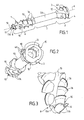
- Les figures 1 et 2 illustrent selon des vues en perspective générale, un exemple de réalisation d'une vis d'ostéosynthèse et de compression conforme à l'invention.
- La figure 3 illustre, selon une vue en perspective partielle, la conformation de la partie la plus distale de la vis conforme à l'invention.
- Figures 1 and 2 illustrate according to views in general perspective, an embodiment of an osteosynthesis screw and compression according to the invention.
- Figure 3 illustrates, in a partial perspective view, the conformation of the most distal portion of the screw according to the invention.
La vis d'ostéosynthèse et de compression illustrée aux figures est destinée à assurer la solidarisation ou la coaptation de deux petits fragments d'os et en particulier, à titre d'application préférentielle, de deux phalanges du pied ou de la main qui ont été fracturées.The osteosynthesis and compression screw illustrated in the figures is intended for ensure the joining or coaptation of two small bone fragments and particular, as a preferential application, two phalanges of the foot or of the hand that have been fractured.
La vis d'ostéosynthèse et de compression conforme à l'invention est réalisée à partir d'un matériau métallique biocompatible et est formée par un corps longitudinal unique présentant un axe longitudinal A formant un axe de révolution.The osteosynthesis and compression screw according to the invention is produced from a biocompatible metallic material and is formed by a body longitudinal axis having a longitudinal axis A forming an axis revolution.
Telle qu'illustrée aux figures, la vis d'ostéosynthèse comprend une partie
proximale 2 formée par une tête de vis 3 pourvue d'un filetage externe 4
comprenant une série de filets hélicoïdaux 4A, ladite partie proximale 2 étant
d'un diamètre D et supérieure au reste de la vis.As illustrated in the figures, the osteosynthesis screw comprises a part
proximal 2 formed by a
La vis d'ostéosynthèse conforme à l'invention comporte ensuite une partie intermédiaire 5 dépourvue de filetage, se présentant avantageusement sous la forme d'une partie sensiblement cylindrique 5A, lisse, de diamètre constant.The osteosynthesis screw according to the invention then comprises a part intermediate 5 without thread, which is advantageously under the shape of a substantially cylindrical portion 5A, smooth, of diameter constant.
La partie terminale de la partie intermédiaire 5 se prolonge par la partie
distale 6 de la vis d'ostéosynthèse, ladite partie distale étant pourvue d'un
filetage externe 7 s'étendant de manière hélicoïdale, par l'intermédiaire de
ses filets 7A jusqu'à la zone terminale 8 de ladite partie distale 6.The terminal part of the
Selon l'invention, la tête de vis 3 et la partie distale 6 comportent chacune au
moins une gorge 10, d'une part s'étendant sensiblement longitudinalement,
en considérant la direction générale donnée par l'axe longitudinal A, sur
toute la longueur axiale de chaque filetage 4, 7, quelle que soit la géométrie
de la gorge 10, c'est-à-dire par exemple longitudinale ou avantageusement
hélicoïdale, et d'autre part ménagées à travers chaque filetage 4, 7, c'est à
dire à travers la hauteur de chaque filet 4A, 7A, de manière à former des
moyens de taraudage de la vis. La vis selon l'invention comporte donc au
moins une paire de gorges 10 pour réaliser un taraudage pour la partie
distale et la partie proximale.According to the invention, the
Selon l'invention, la vis d'ostéosynthèse comprend également au niveau de
la zone terminale 8 de la partie distale 6, des moyens de préparation 11,
dans les fragments d'os, d'un logement destiné à recevoir ultérieurement les
parties intermédiaire 5 et distale 6 de ladite vis.According to the invention, the osteosynthesis screw also comprises at the level of
the
Avantageusement, l'effet de compression est obtenu en prévoyant de
réaliser la vis avec un filetage de la partie proximale 2 qui d'un pas inférieur
au filetage de la partie distale 6.Advantageously, the compression effect is obtained by providing
make the screw with a thread of the
Grâce aux moyens techniques ainsi mis en oeuvre, la vis d'ostéosynthèse
conforme à l'invention permet non seulement une mise en compression
axiale des deux fragments d'os à solidariser grâce à la présence des deux
filetages externes 4 et 7, en combinaison avec la partie intermédiaire 5, dont
l'aspect lisse permet le glissement relatif des deux fragments d'os l'un vers
l'autre, mais encore une action auto-perforante grâce aux moyens de
préparation 11 et surtout une action auto-taraudante conjointe et simultanée
au niveau de la tête de vis 3 et de la partie distale 6. Cette particularité de
conception évite d'avoir recours à un perçage ou chambrage préalable à
l'aide d'un instrument spécifique ce qui réduit la durée totale de l'intervention
chirurgicale tout en réduisant les risques de mise en place défectueuse en
raison de l'existence d'une seule et unique action et opération de mise en
place et de compression.Thanks to the technical means thus implemented, the osteosynthesis screw
according to the invention allows not only compression
axial axis of the two bone fragments to be joined thanks to the presence of the two
Telle qu'illustrée aux figures, ladite au moins une gorge 10 présente aussi
bien au niveau de la tête de vis 3 que de la partie distale 6, est
avantageusement de forme hélicoïdale et de même orientation géométrique
au niveau de la tête de vis 3 et de la partie distale 6 autour de l'axe
longitudinal A. L'aspect hélicoïdal des gorges 10 peut être plus ou moins
prononcé selon la taille et la conformation de la vis sans pour autant sortir du
cadre de l'invention. L'orientation géométrique de l'hélice peut être qualifiée
en définissant son obliquité ou orientation angulaire par rapport à l'axe
longitudinal A de la vis. A titre préférentiel, l'obliquité de chaque gorge 10
sera avantageusement comprise entre 20° et 40°, et préférentiellement
d'environ 25°. Avantageusement, les obliquités des gorges 10 de la tête de
vis 3 et de la partie distale 4 sont égales.As illustrated in the figures, said at least one
Bien évidemment, à titre de variante, la ou les paires de gorges 10 peuvent
être sensiblement longitudinale(s), c'est à dire s'étendre sensiblement
parallèlement à l'axe longitudinal A sans pour autant sortir du cadre de
l'invention.Of course, as a variant, the pair or pairs of
La profondeur de chaque gorge 10 peut être constante et égale entre les
gorges de la tête de vis 3 et de la partie distale 6.The depth of each
Néanmoins, de manière avantageuse, la profondeur des gorges 10 est
régulièrement variable du début vers la fin de chaque gorge, le début de
chaque gorge 10 étant, par définition au sens de l'invention, considéré
comme étant celui débutant à la partie la plus proximale de la tête de vis 3 et
de la partie distale 6. Ainsi, selon l'invention, la profondeur de chaque
gorge 10 croít en direction de chaque partie la plus distale de la tête de vis 3
et de la partie distale 6. Ainsi, la profondeur de chaque gorge est de plus en
plus importante dans chaque filetage 10 à partir de la tête de vis 3 vers la
partie distale 6, c'est à dire vers la zone terminale 8.Nevertheless, advantageously, the depth of the
Cette particularité qui permet de ne pas avoir une profondeur de gorge 10
constante par rapport à l'axe longitudinal A de la vis, améliore la résistance
mécanique générale de la vis, en particulier à la torsion, en réduisant
sensiblement la perte de matière relativement audit axe longitudinal A.This feature that allows not to have a
La minimisation de la faiblesse relative mécanique de la vis selon l'invention
est par ailleurs rendue également possible par le recours à des gorges 10
hélicoïdales permettant de répartir des zones de faiblesse résultant de
l'enlèvement de matières causées par la gorge 10, autour de l'axe
longitudinal A.Minimization of the mechanical relative weakness of the screw according to the invention
is also made possible by the use of
De manière particulièrement avantageuse, la section transversale des
gorges 10 forme un angle aigu, dans tous les cas inférieur à 90°, afin de
réduire la masse de matière enlevée à la vis ce qui diminue une nouvelle fois
la fragilisation de la vis sans obérer ses propriétés d'auto-taraudage.Particularly advantageously, the cross section of the
Dans le cas de variante de réalisation préférée au sens de l'invention,
mettant en oeuvre une croissance régulière de la profondeur de chaque
gorge 10 en direction de la pointe de la vis, la fraction terminale de la gorge,
c'est à dire sa fraction la plus profonde, sera avantageusement ménagée à
travers l'épaisseur du corps de vis, alors que la portion de début de chaque
gorge 10 est simplement réalisée à travers l'épaisseur des filets 4A, 7A. On
réduit ainsi les risques de fragilisation mécanique de l'ensemble de la vis.In the case of a preferred embodiment within the meaning of the invention,
implementing a steady growth in the depth of each
10 throat towards the tip of the screw, the terminal fraction of the throat,
that is to say, its deepest fraction, will advantageously be
through the thickness of the screw body, while the beginning portion of each
A titre de variante préférentielle, les moyens de préparation 11 sont formés
par une dent 11A s'étendant sensiblement axialement.As a preferred variant, the preparation means 11 are formed
by a
Bien que dans sa forme la plus simple, la vis d'ostéosynthèse conforme à
l'invention peut comporter une seule paire de gorges 10 au niveau de la tête
de vis 3 et de la partie distale 6, on comprend qu'il est possible d'améliorer
les propriétés d'auto-perforation et d'auto-taraudage de la vis en ménageant
deux paires de gorges 10, voire de manière encore plus préférentielle, trois
paires de gorges 10 régulièrement réparties angulairement autour de l'axe
longitudinal A et ménagées à la fois dans les parties proximale et distale de
la vis.Although in its simplest form, the osteosynthesis screw complies with
the invention may comprise a single pair of
De manière particulièrement avantageuse, les deux gorges 10 d'une même
paire, qu'elles soient longitudinales ou hélicoïdales, peuvent être ménagées
dans les parties proximale 2 et distale 6 de la vis, de manière à être dans le
prolongement l'une de l'autre.In a particularly advantageous manner, the two
Bien évidemment, à titre de variante, les deux gorges 10 d'une même paire
peuvent également être ménagées dans les parties proximale 2 et distale 6
de la vis, de manière à être décalées l'une de l'autre, de telle sorte que la
gorge 10 ménagée dans la partie distale 6 de la vis ne soit pas dans le
prolongement de la gorge 10 ménagée dans la partie proximale 2.Of course, as an alternative, the two
Ce décalage peut être réalisé avec des gorges 10 longitudinales ou hélicoïdales.This offset can be achieved with longitudinal grooves or helical.
Dans le cas de deux gorges 10, ces dernières seront avantageusement
opposées diamétralement alors que dans le cas préféré de trois gorges 10,
ces dernières seront disposées à 120° par rapport à l'axe principal A de la
vis.In the case of two
Bien évidemment, il est envisageable, suivant la taille des vis concernées,
de réaliser quatre, voire plus, paires de gorges 10.Of course, it is possible, depending on the size of the screws concerned,
to make four or even more pairs of
La vis d'ostéosynthèse conforme à l'invention pourrait être également, mais
non exclusivement, pourvue d'un perçage central 12 et longitudinal pour
former une vis cannulée tel que cela est bien connu de l'homme du métier. The osteosynthesis screw according to the invention could also be, but
not exclusively, provided with a
Bien évidemment, dans le cas où la vis d'ostéosynthèse conforme à
l'invention est pourvue de trois paires de gorges 10, les moyens de
préparation 11 seront simultanément formés par un nombre apparié de trois
dents 11A disposées à la jonction entre les trois gorges 10 de la partie
distale 6 et le perçage central 12.Obviously, in the case where the osteosynthesis screw complies with
the invention is provided with three pairs of
Les moyens techniques mis en oeuvre dans la vis d'ostéosynthèse et de compression conforme à l'invention permettent ainsi au chirurgien de disposer d'une vis d'ostéosynthèse auto-perforante et auto-taraudante qui peut être mis en place de manière simplifiée, en faisant appel à un nombre limité d'outils sans pour autant obérer ses propriétés de résistance mécanique et de compression.The technical means used in the screw osteosynthesis and compression according to the invention thus allow the surgeon to have a self-drilling and self-tapping osteosynthesis screw which can be implemented in a simplified way, using a number limited tools without compromising its resistance properties mechanical and compression.
En effet, le chirurgien, après avoir positionné relativement les deux fragments d'os à solidariser, peut tout simplement mettre en place la vis d'ostéosynthèse conforme à l'invention puis débuter directement le vissage puisque la vis est à la fois auto-perforante et surtout auto-taraudante sur toute sa longueur.Indeed, the surgeon, having positioned relatively the two bone fragments to join, can simply set up the screw osteosynthesis according to the invention and then start directly screwing since the screw is both self-piercing and especially self-tapping on all its length.
Il n'est ainsi plus nécessaire de faire appel à un outil annexe, préalablement
à la mise en place de la vis pour assurer la préparation et le taraudage non
seulement de la partie distale et intermédiaire de la vis mais encore de la
tête de vis 3.It is thus no longer necessary to use an auxiliary tool, previously
at the setting of the screw to ensure the preparation and tapping no
only the distal and intermediate part of the screw but also the
La présente invention concerne donc également une nouvelle méthode d'intervention chirurgicale dans laquelle la vis d'ostéosynthèse assure elle-même, grâce à sa géométrie, et par simple vissage, à l'aide d'un tournevis, la préparation de son logement et de son taraudage sans que l'on ait besoin de préperçage.The present invention therefore also relates to a new method surgical intervention in which the osteosynthesis screw ensures itself, thanks to its geometry, and by simple screwing, using a screwdriver, the preparation of its housing and its tapping without any need pre-drilling.
Claims (11)
Priority Applications (2)
| Application Number | Priority Date | Filing Date | Title |
|---|---|---|---|
| EP10184707A EP2286749A2 (en) | 2002-07-05 | 2003-07-02 | Compression screw for osteosynthesis |
| EP09002928A EP2156799A2 (en) | 2002-07-05 | 2003-07-02 | Self-tapping and self-drilling compression and osteosynthesis screw |
Applications Claiming Priority (2)
| Application Number | Priority Date | Filing Date | Title |
|---|---|---|---|
| FR0208589 | 2002-07-05 | ||
| FR0208589A FR2841764B1 (en) | 2002-07-05 | 2002-07-05 | SCREW OF OSTEOSYNTHESIS AND SELF-TAPPING AND SELF-FORWARD COMPRESSION |
Publications (2)
| Publication Number | Publication Date |
|---|---|
| EP1378205A1 true EP1378205A1 (en) | 2004-01-07 |
| EP1378205B1 EP1378205B1 (en) | 2009-03-04 |
Family
ID=29720102
Family Applications (3)
| Application Number | Title | Priority Date | Filing Date |
|---|---|---|---|
| EP03356101A Expired - Lifetime EP1378205B1 (en) | 2002-07-05 | 2003-07-02 | Compression screw for osteosynthesis |
| EP10184707A Withdrawn EP2286749A2 (en) | 2002-07-05 | 2003-07-02 | Compression screw for osteosynthesis |
| EP09002928A Withdrawn EP2156799A2 (en) | 2002-07-05 | 2003-07-02 | Self-tapping and self-drilling compression and osteosynthesis screw |
Family Applications After (2)
| Application Number | Title | Priority Date | Filing Date |
|---|---|---|---|
| EP10184707A Withdrawn EP2286749A2 (en) | 2002-07-05 | 2003-07-02 | Compression screw for osteosynthesis |
| EP09002928A Withdrawn EP2156799A2 (en) | 2002-07-05 | 2003-07-02 | Self-tapping and self-drilling compression and osteosynthesis screw |
Country Status (7)
| Country | Link |
|---|---|
| US (2) | US7708738B2 (en) |
| EP (3) | EP1378205B1 (en) |
| JP (1) | JP4485156B2 (en) |
| AT (1) | ATE424154T1 (en) |
| DE (1) | DE60326409D1 (en) |
| ES (1) | ES2325533T3 (en) |
| FR (1) | FR2841764B1 (en) |
Cited By (49)
| Publication number | Priority date | Publication date | Assignee | Title |
|---|---|---|---|---|
| ES2267358A1 (en) * | 2004-09-08 | 2007-03-01 | Mariano Nuñez-Samper Pizarroso | Compression screw for osteo-synthesis of mini bone fragments, has four-lobed track, defined at screw head, which forms threaded orifice for fixation to threaded inner rod of screwdriver |
| WO2008041009A1 (en) * | 2006-10-06 | 2008-04-10 | Dalmatic Lystrup A/S | Leads for use in orthopaedic surgery |
| WO2010089481A1 (en) * | 2009-02-09 | 2010-08-12 | Memometal Technologies | Screw for osteosynthesis and arthrodesis |
| CN101856259A (en) * | 2010-06-24 | 2010-10-13 | 蒋昭霞 | Bone pressure-reducing needle |
| WO2013004238A1 (en) * | 2011-07-01 | 2013-01-10 | Elos Medtech Pinol A/S | Bone implant |
| WO2014011933A1 (en) * | 2012-07-12 | 2014-01-16 | Exsomed Holding Company Llc | Metacarpal bone stabilization device |
| US8715284B2 (en) | 2001-03-30 | 2014-05-06 | Interventional Spine, Inc. | Method and apparatus for bone fixation with secondary compression |
| LU92211B1 (en) * | 2013-06-12 | 2014-12-15 | Christian Dala | Self-drilling surgical screw |
| EP2802294B1 (en) * | 2012-03-08 | 2016-05-18 | Zimmer GmbH | Intramedular locking bone screw for fixation of the big-toe joint |
| US9522070B2 (en) | 2013-03-07 | 2016-12-20 | Interventional Spine, Inc. | Intervertebral implant |
| US9539084B2 (en) | 2012-01-23 | 2017-01-10 | Exsomed International IP. LLC | Devices and methods for tendon repair |
| EP2313028B1 (en) * | 2008-08-11 | 2017-07-19 | aap Implantate AG | Interfernce screw |
| US9839530B2 (en) | 2007-06-26 | 2017-12-12 | DePuy Synthes Products, Inc. | Highly lordosed fusion cage |
| US9883951B2 (en) | 2012-08-30 | 2018-02-06 | Interventional Spine, Inc. | Artificial disc |
| US9895236B2 (en) | 2010-06-24 | 2018-02-20 | DePuy Synthes Products, Inc. | Enhanced cage insertion assembly |
| US9913727B2 (en) | 2015-07-02 | 2018-03-13 | Medos International Sarl | Expandable implant |
| US9931223B2 (en) | 2008-04-05 | 2018-04-03 | DePuy Synthes Products, Inc. | Expandable intervertebral implant |
| US9993349B2 (en) | 2002-06-27 | 2018-06-12 | DePuy Synthes Products, Inc. | Intervertebral disc |
| US10058433B2 (en) | 2012-07-26 | 2018-08-28 | DePuy Synthes Products, Inc. | Expandable implant |
| US10111695B2 (en) | 2001-03-30 | 2018-10-30 | DePuy Synthes Products, Inc. | Distal bone anchors for bone fixation with secondary compression |
| US10188161B2 (en) | 2014-01-06 | 2019-01-29 | Exsomed International IP, LLC | Gloves with sensory windows |
| US10194923B2 (en) | 2016-05-10 | 2019-02-05 | Exsomed International IP, LLC | Tool for percutaneous joint cartilage destruction and preparation for joint fusion |
| US10245091B2 (en) | 2015-12-30 | 2019-04-02 | Exsomed Holding Company, Llc | Dip fusion spike screw |
| US10390963B2 (en) | 2006-12-07 | 2019-08-27 | DePuy Synthes Products, Inc. | Intervertebral implant |
| US10398563B2 (en) | 2017-05-08 | 2019-09-03 | Medos International Sarl | Expandable cage |
| US10433977B2 (en) | 2008-01-17 | 2019-10-08 | DePuy Synthes Products, Inc. | Expandable intervertebral implant and associated method of manufacturing the same |
| US10441330B2 (en) | 2015-05-19 | 2019-10-15 | Exsomed Holding Company, Llc | Distal radius plate |
| US10500062B2 (en) | 2009-12-10 | 2019-12-10 | DePuy Synthes Products, Inc. | Bellows-like expandable interbody fusion cage |
| US10537436B2 (en) | 2016-11-01 | 2020-01-21 | DePuy Synthes Products, Inc. | Curved expandable cage |
| US10548741B2 (en) | 2010-06-29 | 2020-02-04 | DePuy Synthes Products, Inc. | Distractible intervertebral implant |
| WO2020167275A3 (en) * | 2019-02-12 | 2020-09-17 | T.C. Maltepe Üni̇versi̇tesi̇ | A rotation anti-rotation compression screw |
| US10888433B2 (en) | 2016-12-14 | 2021-01-12 | DePuy Synthes Products, Inc. | Intervertebral implant inserter and related methods |
| US10940016B2 (en) | 2017-07-05 | 2021-03-09 | Medos International Sarl | Expandable intervertebral fusion cage |
| US11147604B2 (en) | 2016-01-12 | 2021-10-19 | ExsoMed Corporation | Bone stabilization device |
| US11147681B2 (en) | 2017-09-05 | 2021-10-19 | ExsoMed Corporation | Small bone angled compression screw |
| US11191576B2 (en) | 2017-09-05 | 2021-12-07 | ExsoMed Corporation | Intramedullary threaded nail for radial cortical fixation |
| US11191645B2 (en) | 2017-09-05 | 2021-12-07 | ExsoMed Corporation | Small bone tapered compression screw |
| US11259849B2 (en) | 2013-10-02 | 2022-03-01 | ExsoMed Corporation | Full wrist fusion device |
| US11344424B2 (en) | 2017-06-14 | 2022-05-31 | Medos International Sarl | Expandable intervertebral implant and related methods |
| US11426290B2 (en) | 2015-03-06 | 2022-08-30 | DePuy Synthes Products, Inc. | Expandable intervertebral implant, system, kit and method |
| US11426286B2 (en) | 2020-03-06 | 2022-08-30 | Eit Emerging Implant Technologies Gmbh | Expandable intervertebral implant |
| US11446156B2 (en) | 2018-10-25 | 2022-09-20 | Medos International Sarl | Expandable intervertebral implant, inserter instrument, and related methods |
| US11452607B2 (en) | 2010-10-11 | 2022-09-27 | DePuy Synthes Products, Inc. | Expandable interspinous process spacer implant |
| US11510788B2 (en) | 2016-06-28 | 2022-11-29 | Eit Emerging Implant Technologies Gmbh | Expandable, angularly adjustable intervertebral cages |
| US11596522B2 (en) | 2016-06-28 | 2023-03-07 | Eit Emerging Implant Technologies Gmbh | Expandable and angularly adjustable intervertebral cages with articulating joint |
| US11612491B2 (en) | 2009-03-30 | 2023-03-28 | DePuy Synthes Products, Inc. | Zero profile spinal fusion cage |
| US11752009B2 (en) | 2021-04-06 | 2023-09-12 | Medos International Sarl | Expandable intervertebral fusion cage |
| US11850160B2 (en) | 2021-03-26 | 2023-12-26 | Medos International Sarl | Expandable lordotic intervertebral fusion cage |
| US11911287B2 (en) | 2010-06-24 | 2024-02-27 | DePuy Synthes Products, Inc. | Lateral spondylolisthesis reduction cage |
Families Citing this family (61)
| Publication number | Priority date | Publication date | Assignee | Title |
|---|---|---|---|---|
| FR2841764B1 (en) * | 2002-07-05 | 2005-05-20 | Newdeal Sa | SCREW OF OSTEOSYNTHESIS AND SELF-TAPPING AND SELF-FORWARD COMPRESSION |
| US20060106384A1 (en) * | 2004-11-12 | 2006-05-18 | Reber Erik W | Intramedullary nail assembly |
| ATE524121T1 (en) | 2004-11-24 | 2011-09-15 | Abdou Samy | DEVICES FOR PLACING AN ORTHOPEDIC INTERVERTEBRAL IMPLANT |
| EP1861033B1 (en) * | 2005-03-24 | 2012-06-13 | Synthes GmbH | Device for the cement augmentation of bone implants |
| HRP20050295B1 (en) * | 2005-03-29 | 2010-11-30 | Roth Sandor | The canulated titanium implant for correcting flat feet in children |
| JP4964226B2 (en) * | 2005-04-04 | 2012-06-27 | ジンマー ゲゼルシャフト ミット ベシュレンクテル ハフツング | Pedicle screw |
| US20080003255A1 (en) | 2006-05-10 | 2008-01-03 | Synthes (Usa) | Method for augmenting, reducing, and repairing bone with thermoplastic materials |
| US20090198237A1 (en) * | 2006-05-10 | 2009-08-06 | David Downey | Method for augmenting, reducing, and repairing bone with thermoplastic materials |
| US20080234763A1 (en) * | 2007-03-16 | 2008-09-25 | Patterson Chad J | Surgical compression bone screw |
| ITRM20070590A1 (en) * | 2007-11-13 | 2009-05-14 | 2B1 S R L | SCREW FOR STABILIZATION OF A BONE FRACTURE AND RELATIVE KIT. |
| US8535358B2 (en) * | 2007-11-19 | 2013-09-17 | Medical Facets, Llc | Bone screw and method for manufacturing the same |
| US8257407B2 (en) * | 2008-04-23 | 2012-09-04 | Aryan Henry E | Bone plate system and method |
| US20100087923A1 (en) * | 2008-08-23 | 2010-04-08 | Abdou M Samy | Implants for facet joint repair and methods use |
| US8394132B2 (en) * | 2008-09-16 | 2013-03-12 | Orthohelix Surgical Designs, Inc. | Orthopedic compression screw |
| WO2010093658A2 (en) * | 2009-02-10 | 2010-08-19 | Synthes Usa, Llc | Screw with variable diameter cannulation and driver |
| EP2218415B1 (en) * | 2009-02-16 | 2011-05-04 | Stryker Trauma AG | Bone screw and production method therefor |
| US8652183B1 (en) * | 2009-07-07 | 2014-02-18 | Mari S Truman | Multi-angle orthopedic expansion head fastener |
| US8579947B2 (en) * | 2009-09-14 | 2013-11-12 | Yangguan Wu | Polyporous hollow bone screw |
| ES2439870T3 (en) * | 2009-12-03 | 2014-01-27 | Biedermann Technologies Gmbh & Co. Kg | Bone screw |
| US8764806B2 (en) | 2009-12-07 | 2014-07-01 | Samy Abdou | Devices and methods for minimally invasive spinal stabilization and instrumentation |
| ES2456317T3 (en) | 2010-02-26 | 2014-04-22 | Biedermann Technologies Gmbh & Co. Kg | Bone screw |
| US20140243912A1 (en) * | 2010-05-28 | 2014-08-28 | Jean-Pierre Mobasser | Awl-tipped pedicle screw and method of implanting same |
| US8986007B2 (en) * | 2010-07-13 | 2015-03-24 | Star Generation Limited | Restorable zirconium dioxide-based one piece dental implant |
| SG179322A1 (en) | 2010-10-01 | 2012-04-27 | Infastech Ip Pte Ltd | Threaded fastener |
| US8845728B1 (en) | 2011-09-23 | 2014-09-30 | Samy Abdou | Spinal fixation devices and methods of use |
| US20130226240A1 (en) | 2012-02-22 | 2013-08-29 | Samy Abdou | Spinous process fixation devices and methods of use |
| WO2013173873A1 (en) * | 2012-05-22 | 2013-11-28 | Austofix Group Limited | Bone fixation device |
| US9198767B2 (en) | 2012-08-28 | 2015-12-01 | Samy Abdou | Devices and methods for spinal stabilization and instrumentation |
| US9320617B2 (en) | 2012-10-22 | 2016-04-26 | Cogent Spine, LLC | Devices and methods for spinal stabilization and instrumentation |
| US9687284B2 (en) | 2013-02-13 | 2017-06-27 | Stryker European Holdings I, Llc | Locking peg with extended thread |
| WO2014134328A1 (en) | 2013-02-27 | 2014-09-04 | Coorstek Medical Llc D/B/A Imds | Graft fixation |
| US20140343616A1 (en) * | 2013-04-22 | 2014-11-20 | Daniel Sellers | Arthrodesis compression device |
| US10188489B2 (en) | 2014-04-17 | 2019-01-29 | Star Generation Limited Taiwan Branch | Sinus implant |
| CN104257425A (en) * | 2014-10-22 | 2015-01-07 | 毕宏政 | Self-tapping type bolt with annular gauge |
| CN104382637A (en) * | 2014-11-21 | 2015-03-04 | 毕宏政 | Breakage-preventing external fixing support screw |
| DE102014226493B4 (en) * | 2014-12-18 | 2020-11-12 | Holger Erne | Connecting element for fixing at least two bones or bone fragments of a living being |
| US20170000533A1 (en) | 2015-07-02 | 2017-01-05 | First Ray, LLC | Compression implants, instruments and methods |
| US10292745B2 (en) | 2015-10-07 | 2019-05-21 | Arthrex, Inc. | Devices for generating and applying compression within a body |
| US10857003B1 (en) | 2015-10-14 | 2020-12-08 | Samy Abdou | Devices and methods for vertebral stabilization |
| US10702290B2 (en) | 2015-11-02 | 2020-07-07 | First Ray, LLC | Orthopedic fastener, retainer, and guide |
| US10531905B2 (en) * | 2016-04-19 | 2020-01-14 | Globus Medical, Inc. | Implantable compression screws |
| US11278335B2 (en) | 2016-04-19 | 2022-03-22 | Globus Medical, Inc. | Implantable compression screws |
| FR3052658A1 (en) * | 2016-06-21 | 2017-12-22 | Innoprod Medical | MEDICAL IMPLANT FOR TARGETED INJECTION |
| US10973648B1 (en) | 2016-10-25 | 2021-04-13 | Samy Abdou | Devices and methods for vertebral bone realignment |
| US10744000B1 (en) | 2016-10-25 | 2020-08-18 | Samy Abdou | Devices and methods for vertebral bone realignment |
| US11918262B2 (en) * | 2017-03-30 | 2024-03-05 | K2M, Inc. | Fixation device and method of using the same |
| EP3612117B1 (en) | 2017-04-21 | 2023-09-20 | DePuy Synthes Products, Inc. | Angled flutes in cannulated bone screws |
| US11648037B2 (en) | 2017-05-03 | 2023-05-16 | Advance Research System, Llc | Extension-ready spinal support system with vascular-safe pedicle screw |
| WO2018204676A1 (en) | 2017-05-03 | 2018-11-08 | Advance Research System, Llc | Extension ready spinal support systems |
| CN107320168A (en) * | 2017-08-03 | 2017-11-07 | 大博医疗科技股份有限公司 | Femur fixing device |
| US11179248B2 (en) | 2018-10-02 | 2021-11-23 | Samy Abdou | Devices and methods for spinal implantation |
| BE1026273B1 (en) * | 2018-10-02 | 2019-12-05 | Dr Lootens Tom Bvba | Screw device and assembly |
| EP3897410A2 (en) * | 2018-12-21 | 2021-10-27 | Azurmeds Inc | Instrumental system for a latarjet procedure and corresponding method |
| USD916282S1 (en) * | 2019-02-14 | 2021-04-13 | Field Orthopaedics Pty Ltd | Surgical screw |
| US11583326B2 (en) * | 2020-01-28 | 2023-02-21 | Loubert S. Suddaby | Fusion device |
| US11172969B2 (en) * | 2020-01-28 | 2021-11-16 | Loubert S. Suddaby | Fusion device |
| US11957393B2 (en) | 2020-05-12 | 2024-04-16 | Globus Medical, Inc. | Locking variable length compression screw |
| TWI773142B (en) * | 2021-02-19 | 2022-08-01 | 健寶生技股份有限公司 | Bone locking system and method |
| USD1019954S1 (en) | 2021-02-24 | 2024-03-26 | Medshape, Inc. | Dynamic compression device |
| US11291488B1 (en) | 2021-02-24 | 2022-04-05 | Medshape, Inc. | Dynamic compression devices and processes for making and using same |
| WO2023235783A1 (en) * | 2022-06-03 | 2023-12-07 | Seaspine Orthopedics Corporation | Bone screw apparatus |
Citations (6)
| Publication number | Priority date | Publication date | Assignee | Title |
|---|---|---|---|---|
| US4978350A (en) * | 1986-10-13 | 1990-12-18 | Jaquet Orthopedie S.A. | Transcutaneous pin for fixation of a bone part or fragment |
| WO1997025939A1 (en) * | 1996-01-19 | 1997-07-24 | Astra Aktiebolag | Fixture and prosthesis including the same |
| EP0856293A1 (en) * | 1997-02-04 | 1998-08-05 | Patrice Francois Diebold | Bone screw for connecting small bone fragments |
| EP1145691A1 (en) * | 2000-04-13 | 2001-10-17 | BIOLOK International, Inc. | Buttress thread dental implant |
| US6306140B1 (en) * | 2001-01-17 | 2001-10-23 | Synthes (Usa) | Bone screw |
| US6319254B1 (en) * | 1999-04-22 | 2001-11-20 | Newdeal | Compression osteosynthesis screw, and an ancillaty device for use therewith |
Family Cites Families (15)
| Publication number | Priority date | Publication date | Assignee | Title |
|---|---|---|---|---|
| US38119A (en) * | 1863-04-07 | Improvement in drill-bits | ||
| US142112A (en) * | 1873-08-26 | Improvement in wood-screws | ||
| US1294268A (en) * | 1915-08-26 | 1919-02-11 | Edward C Holmes | Screw-spike. |
| FR856293A (en) * | 1939-02-22 | 1940-06-10 | Vernis Pyrolac Soc D | Manufacture of tapes for phonographic reproduction |
| US4697969A (en) * | 1985-09-06 | 1987-10-06 | Sparkes Wilford S | Wood screw |
| DE3542709A1 (en) * | 1985-12-03 | 1987-06-04 | Jansens & Dieperink Bv | METHOD FOR THE PRODUCTION OF LARGE SPACE CONTAINERS, AND INDIVIDUAL SEGMENTS USED THEREFOR, AND ALIGNMENT TOOL FOR ALIGNING THE SAME |
| CH673086A5 (en) * | 1987-09-08 | 1990-02-15 | Maillefer Auguste Sa | |
| US5102421A (en) * | 1990-06-14 | 1992-04-07 | Wm. E. Anpach, III | Suture anchor and method of forming |
| US6001101A (en) * | 1994-07-05 | 1999-12-14 | Depuy France | Screw device with threaded head for permitting the coaptation of two bone fragments |
| US6604945B1 (en) * | 1994-08-15 | 2003-08-12 | Shedrick D. Jones | Method and apparatus for implantation |
| US5759003A (en) * | 1996-07-22 | 1998-06-02 | Greenway; John Michael | Combined screw and clearance drill |
| US5897319A (en) * | 1997-09-12 | 1999-04-27 | Sulzer Calcitek Inc. | Self-tapping implant with helical flutes |
| US6398785B2 (en) * | 1998-04-14 | 2002-06-04 | Joseph Edward Carchidi | Apparatus for rigidly fixing craniomaxillofacial tissue grafts and bone plates |
| US6402757B1 (en) * | 1999-03-12 | 2002-06-11 | Biomet, Inc. | Cannulated fastener system for repair of bone fracture |
| FR2841764B1 (en) * | 2002-07-05 | 2005-05-20 | Newdeal Sa | SCREW OF OSTEOSYNTHESIS AND SELF-TAPPING AND SELF-FORWARD COMPRESSION |
-
2002
- 2002-07-05 FR FR0208589A patent/FR2841764B1/en not_active Expired - Lifetime
-
2003
- 2003-07-01 JP JP2003270068A patent/JP4485156B2/en not_active Expired - Fee Related
- 2003-07-02 EP EP03356101A patent/EP1378205B1/en not_active Expired - Lifetime
- 2003-07-02 DE DE60326409T patent/DE60326409D1/en not_active Expired - Lifetime
- 2003-07-02 AT AT03356101T patent/ATE424154T1/en not_active IP Right Cessation
- 2003-07-02 ES ES03356101T patent/ES2325533T3/en not_active Expired - Lifetime
- 2003-07-02 EP EP10184707A patent/EP2286749A2/en not_active Withdrawn
- 2003-07-02 EP EP09002928A patent/EP2156799A2/en not_active Withdrawn
- 2003-07-07 US US10/614,496 patent/US7708738B2/en active Active
-
2010
- 2010-03-19 US US12/727,722 patent/US20100174323A1/en not_active Abandoned
Patent Citations (6)
| Publication number | Priority date | Publication date | Assignee | Title |
|---|---|---|---|---|
| US4978350A (en) * | 1986-10-13 | 1990-12-18 | Jaquet Orthopedie S.A. | Transcutaneous pin for fixation of a bone part or fragment |
| WO1997025939A1 (en) * | 1996-01-19 | 1997-07-24 | Astra Aktiebolag | Fixture and prosthesis including the same |
| EP0856293A1 (en) * | 1997-02-04 | 1998-08-05 | Patrice Francois Diebold | Bone screw for connecting small bone fragments |
| US6319254B1 (en) * | 1999-04-22 | 2001-11-20 | Newdeal | Compression osteosynthesis screw, and an ancillaty device for use therewith |
| EP1145691A1 (en) * | 2000-04-13 | 2001-10-17 | BIOLOK International, Inc. | Buttress thread dental implant |
| US6306140B1 (en) * | 2001-01-17 | 2001-10-23 | Synthes (Usa) | Bone screw |
Cited By (89)
| Publication number | Priority date | Publication date | Assignee | Title |
|---|---|---|---|---|
| US8715284B2 (en) | 2001-03-30 | 2014-05-06 | Interventional Spine, Inc. | Method and apparatus for bone fixation with secondary compression |
| US10111695B2 (en) | 2001-03-30 | 2018-10-30 | DePuy Synthes Products, Inc. | Distal bone anchors for bone fixation with secondary compression |
| US10349991B2 (en) | 2001-03-30 | 2019-07-16 | DePuy Synthes Products, Inc. | Method and apparatus for bone fixation with secondary compression |
| US9408648B2 (en) | 2001-03-30 | 2016-08-09 | Interventional Spine, Inc. | Method and apparatus for bone fixation with secondary compression |
| US9993349B2 (en) | 2002-06-27 | 2018-06-12 | DePuy Synthes Products, Inc. | Intervertebral disc |
| ES2267358A1 (en) * | 2004-09-08 | 2007-03-01 | Mariano Nuñez-Samper Pizarroso | Compression screw for osteo-synthesis of mini bone fragments, has four-lobed track, defined at screw head, which forms threaded orifice for fixation to threaded inner rod of screwdriver |
| WO2008041009A1 (en) * | 2006-10-06 | 2008-04-10 | Dalmatic Lystrup A/S | Leads for use in orthopaedic surgery |
| US11712345B2 (en) | 2006-12-07 | 2023-08-01 | DePuy Synthes Products, Inc. | Intervertebral implant |
| US10583015B2 (en) | 2006-12-07 | 2020-03-10 | DePuy Synthes Products, Inc. | Intervertebral implant |
| US11273050B2 (en) | 2006-12-07 | 2022-03-15 | DePuy Synthes Products, Inc. | Intervertebral implant |
| US11432942B2 (en) | 2006-12-07 | 2022-09-06 | DePuy Synthes Products, Inc. | Intervertebral implant |
| US11642229B2 (en) | 2006-12-07 | 2023-05-09 | DePuy Synthes Products, Inc. | Intervertebral implant |
| US11497618B2 (en) | 2006-12-07 | 2022-11-15 | DePuy Synthes Products, Inc. | Intervertebral implant |
| US10390963B2 (en) | 2006-12-07 | 2019-08-27 | DePuy Synthes Products, Inc. | Intervertebral implant |
| US11660206B2 (en) | 2006-12-07 | 2023-05-30 | DePuy Synthes Products, Inc. | Intervertebral implant |
| US10398566B2 (en) | 2006-12-07 | 2019-09-03 | DePuy Synthes Products, Inc. | Intervertebral implant |
| US9839530B2 (en) | 2007-06-26 | 2017-12-12 | DePuy Synthes Products, Inc. | Highly lordosed fusion cage |
| US10973652B2 (en) | 2007-06-26 | 2021-04-13 | DePuy Synthes Products, Inc. | Highly lordosed fusion cage |
| US11622868B2 (en) | 2007-06-26 | 2023-04-11 | DePuy Synthes Products, Inc. | Highly lordosed fusion cage |
| US10433977B2 (en) | 2008-01-17 | 2019-10-08 | DePuy Synthes Products, Inc. | Expandable intervertebral implant and associated method of manufacturing the same |
| US10449058B2 (en) | 2008-01-17 | 2019-10-22 | DePuy Synthes Products, Inc. | Expandable intervertebral implant and associated method of manufacturing the same |
| US11737881B2 (en) | 2008-01-17 | 2023-08-29 | DePuy Synthes Products, Inc. | Expandable intervertebral implant and associated method of manufacturing the same |
| US11712341B2 (en) | 2008-04-05 | 2023-08-01 | DePuy Synthes Products, Inc. | Expandable intervertebral implant |
| US11707359B2 (en) | 2008-04-05 | 2023-07-25 | DePuy Synthes Products, Inc. | Expandable intervertebral implant |
| US11701234B2 (en) | 2008-04-05 | 2023-07-18 | DePuy Synthes Products, Inc. | Expandable intervertebral implant |
| US11602438B2 (en) | 2008-04-05 | 2023-03-14 | DePuy Synthes Products, Inc. | Expandable intervertebral implant |
| US11617655B2 (en) | 2008-04-05 | 2023-04-04 | DePuy Synthes Products, Inc. | Expandable intervertebral implant |
| US9931223B2 (en) | 2008-04-05 | 2018-04-03 | DePuy Synthes Products, Inc. | Expandable intervertebral implant |
| US10449056B2 (en) | 2008-04-05 | 2019-10-22 | DePuy Synthes Products, Inc. | Expandable intervertebral implant |
| US11712342B2 (en) | 2008-04-05 | 2023-08-01 | DePuy Synthes Products, Inc. | Expandable intervertebral implant |
| EP2313028B1 (en) * | 2008-08-11 | 2017-07-19 | aap Implantate AG | Interfernce screw |
| US9504504B2 (en) | 2009-02-09 | 2016-11-29 | Stryker European Holdings I, Llc | Screw for osteosynthesis and arthrodesis |
| FR2941859A1 (en) * | 2009-02-09 | 2010-08-13 | Memometal Technologies | OSTEOSYNTHESIS SCREW. |
| US9011505B2 (en) | 2009-02-09 | 2015-04-21 | Memometal Technologies | Screw for osteosynthesis and arthrodesis |
| WO2010089481A1 (en) * | 2009-02-09 | 2010-08-12 | Memometal Technologies | Screw for osteosynthesis and arthrodesis |
| US11612491B2 (en) | 2009-03-30 | 2023-03-28 | DePuy Synthes Products, Inc. | Zero profile spinal fusion cage |
| US11607321B2 (en) | 2009-12-10 | 2023-03-21 | DePuy Synthes Products, Inc. | Bellows-like expandable interbody fusion cage |
| US10500062B2 (en) | 2009-12-10 | 2019-12-10 | DePuy Synthes Products, Inc. | Bellows-like expandable interbody fusion cage |
| CN101856259A (en) * | 2010-06-24 | 2010-10-13 | 蒋昭霞 | Bone pressure-reducing needle |
| US11872139B2 (en) | 2010-06-24 | 2024-01-16 | DePuy Synthes Products, Inc. | Enhanced cage insertion assembly |
| US11911287B2 (en) | 2010-06-24 | 2024-02-27 | DePuy Synthes Products, Inc. | Lateral spondylolisthesis reduction cage |
| US9895236B2 (en) | 2010-06-24 | 2018-02-20 | DePuy Synthes Products, Inc. | Enhanced cage insertion assembly |
| US10966840B2 (en) | 2010-06-24 | 2021-04-06 | DePuy Synthes Products, Inc. | Enhanced cage insertion assembly |
| US10548741B2 (en) | 2010-06-29 | 2020-02-04 | DePuy Synthes Products, Inc. | Distractible intervertebral implant |
| US11654033B2 (en) | 2010-06-29 | 2023-05-23 | DePuy Synthes Products, Inc. | Distractible intervertebral implant |
| US11452607B2 (en) | 2010-10-11 | 2022-09-27 | DePuy Synthes Products, Inc. | Expandable interspinous process spacer implant |
| WO2013004238A1 (en) * | 2011-07-01 | 2013-01-10 | Elos Medtech Pinol A/S | Bone implant |
| US9539084B2 (en) | 2012-01-23 | 2017-01-10 | Exsomed International IP. LLC | Devices and methods for tendon repair |
| US9642656B2 (en) | 2012-03-08 | 2017-05-09 | Zimmer Gmbh | Intramedullary locking bone screw for fixing the metatarsophalangeal joint of the big toe in foot surgery |
| EP2802294B1 (en) * | 2012-03-08 | 2016-05-18 | Zimmer GmbH | Intramedular locking bone screw for fixation of the big-toe joint |
| WO2014011933A1 (en) * | 2012-07-12 | 2014-01-16 | Exsomed Holding Company Llc | Metacarpal bone stabilization device |
| US9480515B2 (en) | 2012-07-12 | 2016-11-01 | Exsomed International IP, LLC | Metacarpal bone stabilization device |
| US10098680B2 (en) | 2012-07-12 | 2018-10-16 | Exsomed Holding Company Llc | Metacarpal bone stabilization device |
| US10058433B2 (en) | 2012-07-26 | 2018-08-28 | DePuy Synthes Products, Inc. | Expandable implant |
| US9883951B2 (en) | 2012-08-30 | 2018-02-06 | Interventional Spine, Inc. | Artificial disc |
| US11497619B2 (en) | 2013-03-07 | 2022-11-15 | DePuy Synthes Products, Inc. | Intervertebral implant |
| US11850164B2 (en) | 2013-03-07 | 2023-12-26 | DePuy Synthes Products, Inc. | Intervertebral implant |
| US9522070B2 (en) | 2013-03-07 | 2016-12-20 | Interventional Spine, Inc. | Intervertebral implant |
| US10413422B2 (en) | 2013-03-07 | 2019-09-17 | DePuy Synthes Products, Inc. | Intervertebral implant |
| LU92211B1 (en) * | 2013-06-12 | 2014-12-15 | Christian Dala | Self-drilling surgical screw |
| US11259849B2 (en) | 2013-10-02 | 2022-03-01 | ExsoMed Corporation | Full wrist fusion device |
| US11272965B2 (en) | 2013-10-02 | 2022-03-15 | ExsoMed Corporation | Full wrist fusion device |
| US10188161B2 (en) | 2014-01-06 | 2019-01-29 | Exsomed International IP, LLC | Gloves with sensory windows |
| US10925336B2 (en) | 2014-01-06 | 2021-02-23 | ExsoMed Corporation | Gloves with sensory windows |
| US11426290B2 (en) | 2015-03-06 | 2022-08-30 | DePuy Synthes Products, Inc. | Expandable intervertebral implant, system, kit and method |
| US10441330B2 (en) | 2015-05-19 | 2019-10-15 | Exsomed Holding Company, Llc | Distal radius plate |
| US11185357B2 (en) | 2015-05-19 | 2021-11-30 | ExsoMed Corporation | Distal radius plate |
| US9913727B2 (en) | 2015-07-02 | 2018-03-13 | Medos International Sarl | Expandable implant |
| US10245091B2 (en) | 2015-12-30 | 2019-04-02 | Exsomed Holding Company, Llc | Dip fusion spike screw |
| US11147604B2 (en) | 2016-01-12 | 2021-10-19 | ExsoMed Corporation | Bone stabilization device |
| US10194923B2 (en) | 2016-05-10 | 2019-02-05 | Exsomed International IP, LLC | Tool for percutaneous joint cartilage destruction and preparation for joint fusion |
| US11510788B2 (en) | 2016-06-28 | 2022-11-29 | Eit Emerging Implant Technologies Gmbh | Expandable, angularly adjustable intervertebral cages |
| US11596522B2 (en) | 2016-06-28 | 2023-03-07 | Eit Emerging Implant Technologies Gmbh | Expandable and angularly adjustable intervertebral cages with articulating joint |
| US11596523B2 (en) | 2016-06-28 | 2023-03-07 | Eit Emerging Implant Technologies Gmbh | Expandable and angularly adjustable articulating intervertebral cages |
| US10537436B2 (en) | 2016-11-01 | 2020-01-21 | DePuy Synthes Products, Inc. | Curved expandable cage |
| US10888433B2 (en) | 2016-12-14 | 2021-01-12 | DePuy Synthes Products, Inc. | Intervertebral implant inserter and related methods |
| US11446155B2 (en) | 2017-05-08 | 2022-09-20 | Medos International Sarl | Expandable cage |
| US10398563B2 (en) | 2017-05-08 | 2019-09-03 | Medos International Sarl | Expandable cage |
| US11344424B2 (en) | 2017-06-14 | 2022-05-31 | Medos International Sarl | Expandable intervertebral implant and related methods |
| US10940016B2 (en) | 2017-07-05 | 2021-03-09 | Medos International Sarl | Expandable intervertebral fusion cage |
| US11191645B2 (en) | 2017-09-05 | 2021-12-07 | ExsoMed Corporation | Small bone tapered compression screw |
| US11147681B2 (en) | 2017-09-05 | 2021-10-19 | ExsoMed Corporation | Small bone angled compression screw |
| US11191576B2 (en) | 2017-09-05 | 2021-12-07 | ExsoMed Corporation | Intramedullary threaded nail for radial cortical fixation |
| US11446156B2 (en) | 2018-10-25 | 2022-09-20 | Medos International Sarl | Expandable intervertebral implant, inserter instrument, and related methods |
| WO2020167275A3 (en) * | 2019-02-12 | 2020-09-17 | T.C. Maltepe Üni̇versi̇tesi̇ | A rotation anti-rotation compression screw |
| US11426286B2 (en) | 2020-03-06 | 2022-08-30 | Eit Emerging Implant Technologies Gmbh | Expandable intervertebral implant |
| US11806245B2 (en) | 2020-03-06 | 2023-11-07 | Eit Emerging Implant Technologies Gmbh | Expandable intervertebral implant |
| US11850160B2 (en) | 2021-03-26 | 2023-12-26 | Medos International Sarl | Expandable lordotic intervertebral fusion cage |
| US11752009B2 (en) | 2021-04-06 | 2023-09-12 | Medos International Sarl | Expandable intervertebral fusion cage |
Also Published As
| Publication number | Publication date |
|---|---|
| FR2841764B1 (en) | 2005-05-20 |
| ES2325533T3 (en) | 2009-09-08 |
| US20040068261A1 (en) | 2004-04-08 |
| US7708738B2 (en) | 2010-05-04 |
| JP4485156B2 (en) | 2010-06-16 |
| ATE424154T1 (en) | 2009-03-15 |
| JP2004033767A (en) | 2004-02-05 |
| EP1378205B1 (en) | 2009-03-04 |
| FR2841764A1 (en) | 2004-01-09 |
| DE60326409D1 (en) | 2009-04-16 |
| EP2286749A2 (en) | 2011-02-23 |
| EP2156799A2 (en) | 2010-02-24 |
| US20100174323A1 (en) | 2010-07-08 |
Similar Documents
| Publication | Publication Date | Title |
|---|---|---|
| EP1378205B1 (en) | Compression screw for osteosynthesis | |
| EP2393441B1 (en) | Screw for osteosynthesis and arthrodesis | |
| EP1273272B1 (en) | Fixing device for bone portions | |
| EP0856293B1 (en) | Bone screw for connecting small bone fragments | |
| FR2808182A1 (en) | Surgical compression screw for joining two bones together has two threaded portions with different pitches, diameters and angles | |
| FR2760628A1 (en) | SCREW WITH THREADED HEAD FOR OSTEOSYNTHESIS OF BONE FRAGMENTS | |
| EP0230856A1 (en) | Transcutaneous fixation pin for fragments or elements of bones | |
| WO2004107999A2 (en) | Screw comprising two threads with different pitches, used to join two bone segments | |
| EP0695537B1 (en) | Threaded head screw device for setting two bone fragments | |
| FR2788960A1 (en) | Threaded pin for connecting bone fragments has two threaded sections of different diameters with smooth section between | |
| FR2788215A1 (en) | Screw implant with anchoring thread for use in facial surgery or dentistry has thread divided into sections by notches in spiral line | |
| FR2912895A1 (en) | Arthrodesis equipment for e.g. metatarso-phalangeal joint of leg, has anchoring screw engaged in eyelet, and arthrodesis screw with thread adapted to support grip in metatarsal and phalanx, and another thread engaged with tapping of sleeve | |
| WO2000040164A1 (en) | Self-compressive osteosynthesis screw for small bone surgery | |
| FR3000662A3 (en) | Self-drilling and self-tapping bone screw for treatment of e.g. cortical bone, has notch extending from distal edge of screw, along base of cutting face of each tooth, where notch is arranged parallel to axis of screw | |
| EP2863818B1 (en) | Osteosynthesis screw with reduced radial compression | |
| EP1361827B1 (en) | Fixing screw | |
| WO2013175099A1 (en) | Self-compressing osteosynthesis screw | |
| FR3021206A1 (en) | OSTEOSYNTHESIS SCREW FOR SOLIDARIZING BONE FRAGMENTS | |
| WO2006045950A1 (en) | Improvement of surgical implant screws | |
| WO2009053540A1 (en) | Compression screw with threaded head for osteosynthesis | |
| EP1302170A2 (en) | Dowel or screw for setting small bone fragments | |
| FR2932375A1 (en) | Bones distracting device for reducing spondylolisthesis between vertebral bodies of patient, has application unit applying opposed forces on plate and part of screw shaft, where forces are defined on straight line parallel to orifice's axis | |
| WO2006084994A1 (en) | Osteosynthesis equipment | |
| FR2649310A1 (en) | Intrafocal pin with reducing effect for osteosynthesis of fractures | |
| FR2749157A1 (en) | Medullary nail implant for surgery |
Legal Events
| Date | Code | Title | Description |
|---|---|---|---|
| PUAI | Public reference made under article 153(3) epc to a published international application that has entered the european phase |
Free format text: ORIGINAL CODE: 0009012 |
|
| AK | Designated contracting states |
Kind code of ref document: A1 Designated state(s): AT BE BG CH CY CZ DE DK EE ES FI FR GB GR HU IE IT LI LU MC NL PT RO SE SI SK TR |
|
| AX | Request for extension of the european patent |
Extension state: AL LT LV MK |
|
| RAP1 | Party data changed (applicant data changed or rights of an application transferred) |
Owner name: NEWDEAL S.A. |
|
| 17P | Request for examination filed |
Effective date: 20040416 |
|
| REG | Reference to a national code |
Ref country code: HK Ref legal event code: DE Ref document number: 1061506 Country of ref document: HK |
|
| AKX | Designation fees paid |
Designated state(s): AT BE BG CH CY CZ DE DK EE ES FI FR GB GR HU IE IT LI LU MC NL PT RO SE SI SK TR |
|
| 17Q | First examination report despatched |
Effective date: 20050621 |
|
| RAP1 | Party data changed (applicant data changed or rights of an application transferred) |
Owner name: NEWDEAL S.A.S |
|
| 17Q | First examination report despatched |
Effective date: 20050621 |
|
| GRAP | Despatch of communication of intention to grant a patent |
Free format text: ORIGINAL CODE: EPIDOSNIGR1 |
|
| GRAS | Grant fee paid |
Free format text: ORIGINAL CODE: EPIDOSNIGR3 |
|
| GRAA | (expected) grant |
Free format text: ORIGINAL CODE: 0009210 |
|
| AK | Designated contracting states |
Kind code of ref document: B1 Designated state(s): AT BE BG CH CY CZ DE DK EE ES FI FR GB GR HU IE IT LI LU MC NL PT RO SE SI SK TR |
|
| REG | Reference to a national code |
Ref country code: GB Ref legal event code: FG4D Free format text: NOT ENGLISH |
|
| REG | Reference to a national code |
Ref country code: CH Ref legal event code: EP |
|
| REG | Reference to a national code |
Ref country code: IE Ref legal event code: FG4D Free format text: LANGUAGE OF EP DOCUMENT: FRENCH |
|
| REF | Corresponds to: |
Ref document number: 60326409 Country of ref document: DE Date of ref document: 20090416 Kind code of ref document: P |
|
| PG25 | Lapsed in a contracting state [announced via postgrant information from national office to epo] |
Ref country code: NL Free format text: LAPSE BECAUSE OF FAILURE TO SUBMIT A TRANSLATION OF THE DESCRIPTION OR TO PAY THE FEE WITHIN THE PRESCRIBED TIME-LIMIT Effective date: 20090304 Ref country code: FI Free format text: LAPSE BECAUSE OF FAILURE TO SUBMIT A TRANSLATION OF THE DESCRIPTION OR TO PAY THE FEE WITHIN THE PRESCRIBED TIME-LIMIT Effective date: 20090304 Ref country code: SI Free format text: LAPSE BECAUSE OF FAILURE TO SUBMIT A TRANSLATION OF THE DESCRIPTION OR TO PAY THE FEE WITHIN THE PRESCRIBED TIME-LIMIT Effective date: 20090304 |
|
| NLV1 | Nl: lapsed or annulled due to failure to fulfill the requirements of art. 29p and 29m of the patents act | ||
| PG25 | Lapsed in a contracting state [announced via postgrant information from national office to epo] |
Ref country code: SE Free format text: LAPSE BECAUSE OF FAILURE TO SUBMIT A TRANSLATION OF THE DESCRIPTION OR TO PAY THE FEE WITHIN THE PRESCRIBED TIME-LIMIT Effective date: 20090604 Ref country code: AT Free format text: LAPSE BECAUSE OF FAILURE TO SUBMIT A TRANSLATION OF THE DESCRIPTION OR TO PAY THE FEE WITHIN THE PRESCRIBED TIME-LIMIT Effective date: 20090304 |
|
| REG | Reference to a national code |
Ref country code: CH Ref legal event code: NV Representative=s name: DR. LUSUARDI AG |
|
| REG | Reference to a national code |
Ref country code: ES Ref legal event code: FG2A Ref document number: 2325533 Country of ref document: ES Kind code of ref document: T3 |
|
| REG | Reference to a national code |
Ref country code: IE Ref legal event code: FD4D |
|
| PG25 | Lapsed in a contracting state [announced via postgrant information from national office to epo] |
Ref country code: EE Free format text: LAPSE BECAUSE OF FAILURE TO SUBMIT A TRANSLATION OF THE DESCRIPTION OR TO PAY THE FEE WITHIN THE PRESCRIBED TIME-LIMIT Effective date: 20090304 Ref country code: CZ Free format text: LAPSE BECAUSE OF FAILURE TO SUBMIT A TRANSLATION OF THE DESCRIPTION OR TO PAY THE FEE WITHIN THE PRESCRIBED TIME-LIMIT Effective date: 20090304 Ref country code: PT Free format text: LAPSE BECAUSE OF FAILURE TO SUBMIT A TRANSLATION OF THE DESCRIPTION OR TO PAY THE FEE WITHIN THE PRESCRIBED TIME-LIMIT Effective date: 20090819 Ref country code: IE Free format text: LAPSE BECAUSE OF FAILURE TO SUBMIT A TRANSLATION OF THE DESCRIPTION OR TO PAY THE FEE WITHIN THE PRESCRIBED TIME-LIMIT Effective date: 20090304 |
|
| PG25 | Lapsed in a contracting state [announced via postgrant information from national office to epo] |
Ref country code: SK Free format text: LAPSE BECAUSE OF FAILURE TO SUBMIT A TRANSLATION OF THE DESCRIPTION OR TO PAY THE FEE WITHIN THE PRESCRIBED TIME-LIMIT Effective date: 20090304 Ref country code: RO Free format text: LAPSE BECAUSE OF FAILURE TO SUBMIT A TRANSLATION OF THE DESCRIPTION OR TO PAY THE FEE WITHIN THE PRESCRIBED TIME-LIMIT Effective date: 20090304 |
|
| PLBE | No opposition filed within time limit |
Free format text: ORIGINAL CODE: 0009261 |
|
| STAA | Information on the status of an ep patent application or granted ep patent |
Free format text: STATUS: NO OPPOSITION FILED WITHIN TIME LIMIT |
|
| PG25 | Lapsed in a contracting state [announced via postgrant information from national office to epo] |
Ref country code: BG Free format text: LAPSE BECAUSE OF FAILURE TO SUBMIT A TRANSLATION OF THE DESCRIPTION OR TO PAY THE FEE WITHIN THE PRESCRIBED TIME-LIMIT Effective date: 20090604 Ref country code: DK Free format text: LAPSE BECAUSE OF FAILURE TO SUBMIT A TRANSLATION OF THE DESCRIPTION OR TO PAY THE FEE WITHIN THE PRESCRIBED TIME-LIMIT Effective date: 20090304 |
|
| BERE | Be: lapsed |
Owner name: NEWDEAL S.A.S Effective date: 20090731 |
|
| 26N | No opposition filed |
Effective date: 20091207 |
|
| PG25 | Lapsed in a contracting state [announced via postgrant information from national office to epo] |
Ref country code: MC Free format text: LAPSE BECAUSE OF NON-PAYMENT OF DUE FEES Effective date: 20090731 |
|
| PG25 | Lapsed in a contracting state [announced via postgrant information from national office to epo] |
Ref country code: BE Free format text: LAPSE BECAUSE OF NON-PAYMENT OF DUE FEES Effective date: 20090731 |
|
| PG25 | Lapsed in a contracting state [announced via postgrant information from national office to epo] |
Ref country code: GR Free format text: LAPSE BECAUSE OF FAILURE TO SUBMIT A TRANSLATION OF THE DESCRIPTION OR TO PAY THE FEE WITHIN THE PRESCRIBED TIME-LIMIT Effective date: 20090605 |
|
| REG | Reference to a national code |
Ref country code: HK Ref legal event code: WD Ref document number: 1061506 Country of ref document: HK |
|
| PG25 | Lapsed in a contracting state [announced via postgrant information from national office to epo] |
Ref country code: LU Free format text: LAPSE BECAUSE OF NON-PAYMENT OF DUE FEES Effective date: 20090702 |
|
| PG25 | Lapsed in a contracting state [announced via postgrant information from national office to epo] |
Ref country code: HU Free format text: LAPSE BECAUSE OF FAILURE TO SUBMIT A TRANSLATION OF THE DESCRIPTION OR TO PAY THE FEE WITHIN THE PRESCRIBED TIME-LIMIT Effective date: 20090905 |
|
| PGFP | Annual fee paid to national office [announced via postgrant information from national office to epo] |
Ref country code: CH Payment date: 20110624 Year of fee payment: 9 |
|
| PG25 | Lapsed in a contracting state [announced via postgrant information from national office to epo] |
Ref country code: TR Free format text: LAPSE BECAUSE OF FAILURE TO SUBMIT A TRANSLATION OF THE DESCRIPTION OR TO PAY THE FEE WITHIN THE PRESCRIBED TIME-LIMIT Effective date: 20090304 |
|
| PG25 | Lapsed in a contracting state [announced via postgrant information from national office to epo] |
Ref country code: CY Free format text: LAPSE BECAUSE OF FAILURE TO SUBMIT A TRANSLATION OF THE DESCRIPTION OR TO PAY THE FEE WITHIN THE PRESCRIBED TIME-LIMIT Effective date: 20090304 |
|
| PGFP | Annual fee paid to national office [announced via postgrant information from national office to epo] |
Ref country code: IT Payment date: 20110618 Year of fee payment: 9 |
|
| PGFP | Annual fee paid to national office [announced via postgrant information from national office to epo] |
Ref country code: ES Payment date: 20110715 Year of fee payment: 9 |
|
| REG | Reference to a national code |
Ref country code: CH Ref legal event code: PL |
|
| PG25 | Lapsed in a contracting state [announced via postgrant information from national office to epo] |
Ref country code: CH Free format text: LAPSE BECAUSE OF NON-PAYMENT OF DUE FEES Effective date: 20120731 Ref country code: LI Free format text: LAPSE BECAUSE OF NON-PAYMENT OF DUE FEES Effective date: 20120731 |
|
| PG25 | Lapsed in a contracting state [announced via postgrant information from national office to epo] |
Ref country code: IT Free format text: LAPSE BECAUSE OF NON-PAYMENT OF DUE FEES Effective date: 20120702 |
|
| REG | Reference to a national code |
Ref country code: ES Ref legal event code: FD2A Effective date: 20131022 |
|
| PG25 | Lapsed in a contracting state [announced via postgrant information from national office to epo] |
Ref country code: ES Free format text: LAPSE BECAUSE OF NON-PAYMENT OF DUE FEES Effective date: 20120703 |
|
| REG | Reference to a national code |
Ref country code: FR Ref legal event code: PLFP Year of fee payment: 14 |
|
| REG | Reference to a national code |
Ref country code: FR Ref legal event code: PLFP Year of fee payment: 15 |
|
| REG | Reference to a national code |
Ref country code: FR Ref legal event code: PLFP Year of fee payment: 16 |
|
| REG | Reference to a national code |
Ref country code: DE Ref legal event code: R082 Ref document number: 60326409 Country of ref document: DE Representative=s name: MURGITROYD GERMANY PATENTANWALTSGESELLSCHAFT M, DE Ref country code: DE Ref legal event code: R082 Ref document number: 60326409 Country of ref document: DE Representative=s name: MURGITROYD & COMPANY, DE Ref country code: DE Ref legal event code: R081 Ref document number: 60326409 Country of ref document: DE Owner name: SMITH & NEPHEW, INC., WILMINGTON, US Free format text: FORMER OWNER: NEWDEAL S.A.S. IMMEUBLE SEQUOIA 2, SAINT PRIEST, FR Ref country code: DE Ref legal event code: R081 Ref document number: 60326409 Country of ref document: DE Owner name: SMITH & NEPHEW ASIA PACIFIC PTE LIMITED, SG Free format text: FORMER OWNER: NEWDEAL S.A.S. IMMEUBLE SEQUOIA 2, SAINT PRIEST, FR Ref country code: DE Ref legal event code: R081 Ref document number: 60326409 Country of ref document: DE Owner name: SMITH & NEPHEW ORTHOPAEDICS AG, CH Free format text: FORMER OWNER: NEWDEAL S.A.S. IMMEUBLE SEQUOIA 2, SAINT PRIEST, FR |
|
| REG | Reference to a national code |
Ref country code: GB Ref legal event code: 732E Free format text: REGISTERED BETWEEN 20210624 AND 20210630 |
|
| REG | Reference to a national code |
Ref country code: DE Ref legal event code: R081 Ref document number: 60326409 Country of ref document: DE Owner name: SMITH & NEPHEW ORTHOPAEDICS AG, CH Free format text: FORMER OWNERS: SMITH & NEPHEW, INC., WILMINGTON, DE, US; SMITH & NEPHEW ASIA PACIFIC PTE LIMITED, SINGAPORE, SG; SMITH & NEPHEW ORTHOPAEDICS AG, ZUG, CH |
|
| REG | Reference to a national code |
Ref country code: GB Ref legal event code: 732E Free format text: REGISTERED BETWEEN 20210805 AND 20210811 |
|
| PGFP | Annual fee paid to national office [announced via postgrant information from national office to epo] |
Ref country code: FR Payment date: 20220623 Year of fee payment: 20 |
|
| PGFP | Annual fee paid to national office [announced via postgrant information from national office to epo] |
Ref country code: GB Payment date: 20220706 Year of fee payment: 20 Ref country code: DE Payment date: 20220608 Year of fee payment: 20 |
|
| REG | Reference to a national code |
Ref country code: DE Ref legal event code: R071 Ref document number: 60326409 Country of ref document: DE |
|
| P01 | Opt-out of the competence of the unified patent court (upc) registered |
Effective date: 20230528 |
|
| REG | Reference to a national code |
Ref country code: GB Ref legal event code: PE20 Expiry date: 20230701 |
|
| PG25 | Lapsed in a contracting state [announced via postgrant information from national office to epo] |
Ref country code: GB Free format text: LAPSE BECAUSE OF EXPIRATION OF PROTECTION Effective date: 20230701 |