EP1386804A1 - Wheel lift identification for an automotive vehicle - Google Patents
Wheel lift identification for an automotive vehicle Download PDFInfo
- Publication number
- EP1386804A1 EP1386804A1 EP03254816A EP03254816A EP1386804A1 EP 1386804 A1 EP1386804 A1 EP 1386804A1 EP 03254816 A EP03254816 A EP 03254816A EP 03254816 A EP03254816 A EP 03254816A EP 1386804 A1 EP1386804 A1 EP 1386804A1
- Authority
- EP
- European Patent Office
- Prior art keywords
- wheel
- lift
- pressure request
- executed
- roll control
- Prior art date
- Legal status (The legal status is an assumption and is not a legal conclusion. Google has not performed a legal analysis and makes no representation as to the accuracy of the status listed.)
- Granted
Links
- 230000000977 initiatory effect Effects 0.000 claims abstract description 9
- 230000004044 response Effects 0.000 claims abstract description 7
- 238000000034 method Methods 0.000 claims description 23
- 230000008859 change Effects 0.000 claims description 16
- 238000012544 monitoring process Methods 0.000 claims 1
- 238000001514 detection method Methods 0.000 description 17
- 230000001133 acceleration Effects 0.000 description 12
- 230000008569 process Effects 0.000 description 4
- 230000001276 controlling effect Effects 0.000 description 2
- 230000001629 suppression Effects 0.000 description 2
- 230000009471 action Effects 0.000 description 1
- 230000008901 benefit Effects 0.000 description 1
- 230000005540 biological transmission Effects 0.000 description 1
- 238000012790 confirmation Methods 0.000 description 1
- 238000012937 correction Methods 0.000 description 1
- 230000000694 effects Effects 0.000 description 1
- 230000007246 mechanism Effects 0.000 description 1
- 230000001151 other effect Effects 0.000 description 1
- 230000002265 prevention Effects 0.000 description 1
- 230000001105 regulatory effect Effects 0.000 description 1
- 238000005096 rolling process Methods 0.000 description 1
- 239000000725 suspension Substances 0.000 description 1
- 238000012360 testing method Methods 0.000 description 1
- 238000012546 transfer Methods 0.000 description 1
Images


Classifications
-
- B—PERFORMING OPERATIONS; TRANSPORTING
- B60—VEHICLES IN GENERAL
- B60R—VEHICLES, VEHICLE FITTINGS, OR VEHICLE PARTS, NOT OTHERWISE PROVIDED FOR
- B60R21/00—Arrangements or fittings on vehicles for protecting or preventing injuries to occupants or pedestrians in case of accidents or other traffic risks
- B60R21/01—Electrical circuits for triggering passive safety arrangements, e.g. airbags, safety belt tighteners, in case of vehicle accidents or impending vehicle accidents
- B60R21/013—Electrical circuits for triggering passive safety arrangements, e.g. airbags, safety belt tighteners, in case of vehicle accidents or impending vehicle accidents including means for detecting collisions, impending collisions or roll-over
- B60R21/0132—Electrical circuits for triggering passive safety arrangements, e.g. airbags, safety belt tighteners, in case of vehicle accidents or impending vehicle accidents including means for detecting collisions, impending collisions or roll-over responsive to vehicle motion parameters, e.g. to vehicle longitudinal or transversal deceleration or speed value
-
- B—PERFORMING OPERATIONS; TRANSPORTING
- B60—VEHICLES IN GENERAL
- B60G—VEHICLE SUSPENSION ARRANGEMENTS
- B60G17/00—Resilient suspensions having means for adjusting the spring or vibration-damper characteristics, for regulating the distance between a supporting surface and a sprung part of vehicle or for locking suspension during use to meet varying vehicular or surface conditions, e.g. due to speed or load
- B60G17/015—Resilient suspensions having means for adjusting the spring or vibration-damper characteristics, for regulating the distance between a supporting surface and a sprung part of vehicle or for locking suspension during use to meet varying vehicular or surface conditions, e.g. due to speed or load the regulating means comprising electric or electronic elements
- B60G17/016—Resilient suspensions having means for adjusting the spring or vibration-damper characteristics, for regulating the distance between a supporting surface and a sprung part of vehicle or for locking suspension during use to meet varying vehicular or surface conditions, e.g. due to speed or load the regulating means comprising electric or electronic elements characterised by their responsiveness, when the vehicle is travelling, to specific motion, a specific condition, or driver input
- B60G17/0162—Resilient suspensions having means for adjusting the spring or vibration-damper characteristics, for regulating the distance between a supporting surface and a sprung part of vehicle or for locking suspension during use to meet varying vehicular or surface conditions, e.g. due to speed or load the regulating means comprising electric or electronic elements characterised by their responsiveness, when the vehicle is travelling, to specific motion, a specific condition, or driver input mainly during a motion involving steering operation, e.g. cornering, overtaking
-
- B—PERFORMING OPERATIONS; TRANSPORTING
- B60—VEHICLES IN GENERAL
- B60G—VEHICLE SUSPENSION ARRANGEMENTS
- B60G17/00—Resilient suspensions having means for adjusting the spring or vibration-damper characteristics, for regulating the distance between a supporting surface and a sprung part of vehicle or for locking suspension during use to meet varying vehicular or surface conditions, e.g. due to speed or load
- B60G17/015—Resilient suspensions having means for adjusting the spring or vibration-damper characteristics, for regulating the distance between a supporting surface and a sprung part of vehicle or for locking suspension during use to meet varying vehicular or surface conditions, e.g. due to speed or load the regulating means comprising electric or electronic elements
- B60G17/0195—Resilient suspensions having means for adjusting the spring or vibration-damper characteristics, for regulating the distance between a supporting surface and a sprung part of vehicle or for locking suspension during use to meet varying vehicular or surface conditions, e.g. due to speed or load the regulating means comprising electric or electronic elements characterised by the regulation being combined with other vehicle control systems
-
- B—PERFORMING OPERATIONS; TRANSPORTING
- B60—VEHICLES IN GENERAL
- B60R—VEHICLES, VEHICLE FITTINGS, OR VEHICLE PARTS, NOT OTHERWISE PROVIDED FOR
- B60R16/00—Electric or fluid circuits specially adapted for vehicles and not otherwise provided for; Arrangement of elements of electric or fluid circuits specially adapted for vehicles and not otherwise provided for
- B60R16/02—Electric or fluid circuits specially adapted for vehicles and not otherwise provided for; Arrangement of elements of electric or fluid circuits specially adapted for vehicles and not otherwise provided for electric constitutive elements
- B60R16/023—Electric or fluid circuits specially adapted for vehicles and not otherwise provided for; Arrangement of elements of electric or fluid circuits specially adapted for vehicles and not otherwise provided for electric constitutive elements for transmission of signals between vehicle parts or subsystems
- B60R16/0231—Circuits relating to the driving or the functioning of the vehicle
- B60R16/0232—Circuits relating to the driving or the functioning of the vehicle for measuring vehicle parameters and indicating critical, abnormal or dangerous conditions
- B60R16/0233—Vehicle tilting, overturning or roll over
-
- B—PERFORMING OPERATIONS; TRANSPORTING
- B60—VEHICLES IN GENERAL
- B60R—VEHICLES, VEHICLE FITTINGS, OR VEHICLE PARTS, NOT OTHERWISE PROVIDED FOR
- B60R21/00—Arrangements or fittings on vehicles for protecting or preventing injuries to occupants or pedestrians in case of accidents or other traffic risks
- B60R21/01—Electrical circuits for triggering passive safety arrangements, e.g. airbags, safety belt tighteners, in case of vehicle accidents or impending vehicle accidents
- B60R21/013—Electrical circuits for triggering passive safety arrangements, e.g. airbags, safety belt tighteners, in case of vehicle accidents or impending vehicle accidents including means for detecting collisions, impending collisions or roll-over
-
- B—PERFORMING OPERATIONS; TRANSPORTING
- B60—VEHICLES IN GENERAL
- B60T—VEHICLE BRAKE CONTROL SYSTEMS OR PARTS THEREOF; BRAKE CONTROL SYSTEMS OR PARTS THEREOF, IN GENERAL; ARRANGEMENT OF BRAKING ELEMENTS ON VEHICLES IN GENERAL; PORTABLE DEVICES FOR PREVENTING UNWANTED MOVEMENT OF VEHICLES; VEHICLE MODIFICATIONS TO FACILITATE COOLING OF BRAKES
- B60T8/00—Arrangements for adjusting wheel-braking force to meet varying vehicular or ground-surface conditions, e.g. limiting or varying distribution of braking force
- B60T8/17—Using electrical or electronic regulation means to control braking
- B60T8/172—Determining control parameters used in the regulation, e.g. by calculations involving measured or detected parameters
-
- B—PERFORMING OPERATIONS; TRANSPORTING
- B60—VEHICLES IN GENERAL
- B60T—VEHICLE BRAKE CONTROL SYSTEMS OR PARTS THEREOF; BRAKE CONTROL SYSTEMS OR PARTS THEREOF, IN GENERAL; ARRANGEMENT OF BRAKING ELEMENTS ON VEHICLES IN GENERAL; PORTABLE DEVICES FOR PREVENTING UNWANTED MOVEMENT OF VEHICLES; VEHICLE MODIFICATIONS TO FACILITATE COOLING OF BRAKES
- B60T8/00—Arrangements for adjusting wheel-braking force to meet varying vehicular or ground-surface conditions, e.g. limiting or varying distribution of braking force
- B60T8/17—Using electrical or electronic regulation means to control braking
- B60T8/1755—Brake regulation specially adapted to control the stability of the vehicle, e.g. taking into account yaw rate or transverse acceleration in a curve
- B60T8/17551—Brake regulation specially adapted to control the stability of the vehicle, e.g. taking into account yaw rate or transverse acceleration in a curve determining control parameters related to vehicle stability used in the regulation, e.g. by calculations involving measured or detected parameters
-
- B—PERFORMING OPERATIONS; TRANSPORTING
- B60—VEHICLES IN GENERAL
- B60T—VEHICLE BRAKE CONTROL SYSTEMS OR PARTS THEREOF; BRAKE CONTROL SYSTEMS OR PARTS THEREOF, IN GENERAL; ARRANGEMENT OF BRAKING ELEMENTS ON VEHICLES IN GENERAL; PORTABLE DEVICES FOR PREVENTING UNWANTED MOVEMENT OF VEHICLES; VEHICLE MODIFICATIONS TO FACILITATE COOLING OF BRAKES
- B60T8/00—Arrangements for adjusting wheel-braking force to meet varying vehicular or ground-surface conditions, e.g. limiting or varying distribution of braking force
- B60T8/24—Arrangements for adjusting wheel-braking force to meet varying vehicular or ground-surface conditions, e.g. limiting or varying distribution of braking force responsive to vehicle inclination or change of direction, e.g. negotiating bends
- B60T8/241—Lateral vehicle inclination
- B60T8/243—Lateral vehicle inclination for roll-over protection
-
- B—PERFORMING OPERATIONS; TRANSPORTING
- B60—VEHICLES IN GENERAL
- B60G—VEHICLE SUSPENSION ARRANGEMENTS
- B60G2800/00—Indexing codes relating to the type of movement or to the condition of the vehicle and to the end result to be achieved by the control action
- B60G2800/01—Attitude or posture control
- B60G2800/019—Inclination due to load distribution or road gradient
- B60G2800/0194—Inclination due to load distribution or road gradient transversal with regard to vehicle
-
- B—PERFORMING OPERATIONS; TRANSPORTING
- B60—VEHICLES IN GENERAL
- B60G—VEHICLE SUSPENSION ARRANGEMENTS
- B60G2800/00—Indexing codes relating to the type of movement or to the condition of the vehicle and to the end result to be achieved by the control action
- B60G2800/21—Traction, slip, skid or slide control
- B60G2800/215—Traction, slip, skid or slide control by applying a braking action on each wheel individually
-
- B—PERFORMING OPERATIONS; TRANSPORTING
- B60—VEHICLES IN GENERAL
- B60G—VEHICLE SUSPENSION ARRANGEMENTS
- B60G2800/00—Indexing codes relating to the type of movement or to the condition of the vehicle and to the end result to be achieved by the control action
- B60G2800/90—System Controller type
- B60G2800/92—ABS - Brake Control
- B60G2800/922—EBV - Electronic brake force distribution
-
- B—PERFORMING OPERATIONS; TRANSPORTING
- B60—VEHICLES IN GENERAL
- B60R—VEHICLES, VEHICLE FITTINGS, OR VEHICLE PARTS, NOT OTHERWISE PROVIDED FOR
- B60R21/00—Arrangements or fittings on vehicles for protecting or preventing injuries to occupants or pedestrians in case of accidents or other traffic risks
- B60R2021/0002—Type of accident
- B60R2021/0018—Roll-over
-
- B—PERFORMING OPERATIONS; TRANSPORTING
- B60—VEHICLES IN GENERAL
- B60R—VEHICLES, VEHICLE FITTINGS, OR VEHICLE PARTS, NOT OTHERWISE PROVIDED FOR
- B60R21/00—Arrangements or fittings on vehicles for protecting or preventing injuries to occupants or pedestrians in case of accidents or other traffic risks
- B60R21/01—Electrical circuits for triggering passive safety arrangements, e.g. airbags, safety belt tighteners, in case of vehicle accidents or impending vehicle accidents
- B60R21/013—Electrical circuits for triggering passive safety arrangements, e.g. airbags, safety belt tighteners, in case of vehicle accidents or impending vehicle accidents including means for detecting collisions, impending collisions or roll-over
- B60R21/0132—Electrical circuits for triggering passive safety arrangements, e.g. airbags, safety belt tighteners, in case of vehicle accidents or impending vehicle accidents including means for detecting collisions, impending collisions or roll-over responsive to vehicle motion parameters, e.g. to vehicle longitudinal or transversal deceleration or speed value
- B60R2021/01327—Angular velocity or angular acceleration
-
- B—PERFORMING OPERATIONS; TRANSPORTING
- B60—VEHICLES IN GENERAL
- B60T—VEHICLE BRAKE CONTROL SYSTEMS OR PARTS THEREOF; BRAKE CONTROL SYSTEMS OR PARTS THEREOF, IN GENERAL; ARRANGEMENT OF BRAKING ELEMENTS ON VEHICLES IN GENERAL; PORTABLE DEVICES FOR PREVENTING UNWANTED MOVEMENT OF VEHICLES; VEHICLE MODIFICATIONS TO FACILITATE COOLING OF BRAKES
- B60T2230/00—Monitoring, detecting special vehicle behaviour; Counteracting thereof
- B60T2230/03—Overturn, rollover
-
- B—PERFORMING OPERATIONS; TRANSPORTING
- B60—VEHICLES IN GENERAL
- B60T—VEHICLE BRAKE CONTROL SYSTEMS OR PARTS THEREOF; BRAKE CONTROL SYSTEMS OR PARTS THEREOF, IN GENERAL; ARRANGEMENT OF BRAKING ELEMENTS ON VEHICLES IN GENERAL; PORTABLE DEVICES FOR PREVENTING UNWANTED MOVEMENT OF VEHICLES; VEHICLE MODIFICATIONS TO FACILITATE COOLING OF BRAKES
- B60T2240/00—Monitoring, detecting wheel/tire behaviour; counteracting thereof
- B60T2240/06—Wheel load; Wheel lift
-
- B—PERFORMING OPERATIONS; TRANSPORTING
- B60—VEHICLES IN GENERAL
- B60W—CONJOINT CONTROL OF VEHICLE SUB-UNITS OF DIFFERENT TYPE OR DIFFERENT FUNCTION; CONTROL SYSTEMS SPECIALLY ADAPTED FOR HYBRID VEHICLES; ROAD VEHICLE DRIVE CONTROL SYSTEMS FOR PURPOSES NOT RELATED TO THE CONTROL OF A PARTICULAR SUB-UNIT
- B60W30/00—Purposes of road vehicle drive control systems not related to the control of a particular sub-unit, e.g. of systems using conjoint control of vehicle sub-units, or advanced driver assistance systems for ensuring comfort, stability and safety or drive control systems for propelling or retarding the vehicle
- B60W30/02—Control of vehicle driving stability
- B60W30/04—Control of vehicle driving stability related to roll-over prevention
Definitions
- the present invention relates generally to a dynamic behavior control apparatus for an automotive vehicle, and more specifically, to a method and apparatus for determining whether a wheel of an automotive vehicle has lifted from the pavement or become grounded after being lifted from the pavement.
- Dynamic control systems for automotive vehicles have recently begun to be offered on various products. Dynamic control systems typically control the yaw of the vehicle by controlling the braking effort at various wheels of the vehicle. By regulating the amount of braking at each corner of the vehicle, the desired direction of the vehicle may be maintained.
- the dynamic control systems do not address roll of the vehicle.
- Vehicle rollover and tilt control are distinguishable dynamic characteristics. Tilt control maintains the body on a plane or nearly on a plane parallel to the road surface. Rollover control is used to maintain the vehicle wheels on the road surface.
- Such systems typically use position sensors to measure the relative distance between the vehicle body and the vehicle suspension.
- One drawback to such systems is that the distance from the body to the road must be inferred.
- a method of controlling an automotive vehicle includes detecting a potential for a wheel lift, determining a wheel lift pressure request to determine wheel lift, generating a roll control pressure request, and suppressing the wheel lift pressure request in response to the roll control pressure request, when the wheel lift pressure would hinder or interfere with the delivery of the roll control pressure.
- a method of operating an automotive vehicle includes initiating a build cycle, storing a peak wheel speed after initiating the build cycle, determining a second wheel speed to determine a change in wheel speed from the peak speed, and determining a wheel lift status when the change in the wheel speed is greater than a predetermined value.
- a method of operating an automotive vehicle having an antilock brake system includes initiating an antilock brake monitor mode and determining wheel lift in response to the antilock brake monitor mode.
- One advantage of the invention is that in vehicles employing a dynamic stability control system, additional sensors may not be required.
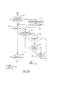
- Figure 1 is a partial cutaway view of an automotive vehicle having a wheel lift identification system according to the present invention.
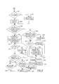
- Figure 2 is a flow chart of a wheel lift identification system according to the present invention.
- Figure 3A is a plot of pressure versus time for a wheel lift identification system according to one embodiment of the present invention.
- Figure 3B is a plot of wheel speed versus time for a wheel lift identification system according to one embodiment of the present invention.
- Figure 4 is a schematic view of a vehicle having a braking system.
- FIGS 5A and 5B are high level flow charts of one embodiment of active wheel lift detection according to the present invention.
- Figures 6A and 6B are flow charts of one embodiment of a build cycle according to the present invention.
- Figures 7A and 7B are flow charts of one embodiment of a release cycle according to the present invention.
- Figure 8 is a high level flow chart of an ABS monitor mode according to the present invention.
- the present invention is described with respect to a wheel lift identification system for an automotive vehicle. Those skilled in the art will recognize that the present invention may be incorporated into a rollover prevention system for an automotive vehicle.
- an automotive vehicle 10 has a plurality of wheels 12, two of which are shown as elevated above a road plane 14.
- a roll control system 16 is included within vehicle 10.
- the roll control system 16 is used to counteract the lifting of wheels 12 from road plane 14 as will be further described below.
- Roll control system 16 includes a roll controller 18 that is preferably microprocessor based.
- Roll controller 18 may be part of a dynamic stability control system of the automotive vehicle 10.
- Roll controller 18 is coupled to a torque control system 20 that is used to control the torque of the wheels 12.
- torque control system 20 is illustrated as a separate item, torque control system 20 may be included in roll controller 18 which may in turn be included within a dynamic stability control system. Such a system may also have an antilock brake controller incorporated therein.
- Torque control system 20 may act in conjunction with the electronic engine controller, a driveline engagement mechanism or braking system, or a combination of these to control the torque at one or all of the wheels 12.
- Torque controller 20 and roll controller 18 may be coupled to wheel speed sensors 22 located at each of the wheels 12. Wheel speed sensors 22 provide roll controller 18 with a signal indicative of the speed of the individual wheel to which it is attached.
- wheel speed sensors 22 provide roll controller 18 with a signal indicative of the speed of the individual wheel to which it is attached.
- Various types of wheel speed sensors including toothed-wheel type systems would be evident to those skilled in the art.
- Other sensors 24 may be coupled to roll control system 16.
- roll angle sensors, steering wheel angle sensors, yaw rate sensors, and other sensors may be incorporated therein.
- Other sensors 24, as will be further described below, may be used to identify a condition suitable for the potential of wheel lift. Such a condition may initiate further action by roll control system 16 to verify wheel lift.
- the application of brake pressure is used to provide the change in torque.
- other methods such as applying engine torque may also be used to change the amount of torque at a wheel.
- Further references to the application of torque to a wheel may include hydraulic or electric brake torque, changes in engine torque or engagement of driveline torque through the use of an electronically controlled transfer case, differential, transmission or clutch.
- the present invention may also be used to determine if a sensor has failed in the roll control system 16. That is, if roll is suspected by a particular sensor, but all other conditions or sensors indicate otherwise, the sensor may be operating improperly.
- speed is used, wheel acceleration may also be used in place of speed as would be evident to those skilled in the art.
- step 30 if a roll sensor failure is suspected or in step 32 if wheel lift is suspected by the roll control system 16, block 34 initiates the wheel lift determination process.
- step 36 torque is applied to the wheel suspected of lifting and the wheel speed at the suspected wheel is stored.
- step 38 the torque is increased by applying a test pulse of torque to the suspected wheel. Torque is applied until a torque threshold (Torque_Max) is achieved.
- Torque_Max torque threshold
- step 40 if the torque is greater than the Torque_Max, the torque is held constant in step 42.
- step 44 if the time as counted by the Build_Counter is greater than a predetermined time, step 46 is executed in which the torque is released and the wheel speed at the initiation of the release of torque is stored.
- step 44 if the counter is not greater than the predetermined hold time, the counter is incremented in step 48.
- step 48 the change in wheel speed is compared to a predetermined change in wheel speed. If the wheel speed change is not greater than a predetermined speed in step 50, steps 38-44 are again executed. If the wheel speed change is greater than a predetermined speed, this indicates a lifted wheel. In this case, step 52 is executed in which a wheel lift status flag is set. After step 52, step 54 is executed in which the build counter is reset.
- step 50 is executed.
- step 56 is executed.
- torque is released.
- step 58 is implemented in which the wheel speed change is compared to a reacceleration threshold.
- the reacceleration threshold is a predetermined value that corresponds to a wheel speed change that should be achieved should wheel contact be reestablished.
- the wheel speed change is determined from the time that the torque was released. If the wheel speed change is greater than a reacceleration threshold or if the wheel lift status from step 52 is zero, wheel contact is assumed. In such a case the traction level may be calculated in step 60. If the wheel speed does not increase over the reacceleration threshold, then the wheel lift status is confirmed beginning with step 70.
- step 62 compares the Dump_Counter to a predetermined dump time. If the predetermined dump time is greater than the Dump_Counter, then the Dump_Counter is incremented in step 64 and steps 56 and 58 are again executed. If the Dump_Counter is greater than the predetermined dump time, then the wheel lift status flag is set in step 66 and the Dump_Counter is reset in step 68. After step 68, the process is reinitiated and returns to step 36.
- step 60 the plausibility of a sensor failure is determined. If, for example, the process was initiated based on the suspicion of a sensor failure from block 30 above and no wheel lift was detected, a sensor failure is indicated in step 72. For either result, if a sensor failure is indicated by block 70 or not, the build counter and Dump_ Counter are cleared in block 74 and the wheel lift status is cleared in block 76. The end of the routine occurs in block 78.
- the application of torque can be used to first determine whether a suspected wheel has lifted from the pavement.
- the removal of the torque and the resulting wheel speed change may be used to confirm the initial finding.
- the system may be implemented in a dynamic stability system of an automotive vehicle without adding further sensors. If rollover is detected, then the rollover can be corrected by applying the brakes or generating a steering correction.
- FIG. 3B a plot of wheel speed corresponding to the various times is illustrated. As shown, the wheel speed of a loaded wheel is illustrated by line 96, which is higher than the wheel speed of a lifted wheel illustrated by line 98.
- automotive vehicle 10 includes wheel speed sensors 22 that are coupled at each wheel 12. Each wheel also has brakes that are hydraulically coupled to a brake system 104 through hydraulic lines 106 and 108. Hydraulic lines 106 are coupled to the front brakes and form a front brake circuit and hydraulic lines 108 are coupled to the rear brakes forming a rear brake circuit. Many vehicles are manufactured in such a configuration in which the front wheels and rear wheels are on different brake circuits.
- Brake system 104 may include an anti-lock brake system controller 110.
- the anti-lock brake system controller 110 is known in the art.
- the anti-lock brake system controller 110 may be an integral part of brake system 104 or a separate component.
- the anti-lock brake system controller 110 builds pressure in the wheels and in response thereto prevents the wheel from locking by releasing the brake pressure thereto.
- a rollover stability control system controller 18' is coupled to brake system 104.
- the rollover stability control system controller 18' may command brake system 104 to provide hydraulic pressure to a front wheel (or rear wheel) to prevent the vehicle from rolling over.
- the wheel lift detection system may apply brakes to change the torque in a tire to detect whether a wheel is lifted.
- the wheel lift pressure request is suppressed on a wheel when there is a large pressure requested on the other wheel of the same hydraulic circuit. That is, when a large roll control pressure request is generated for the same hydraulic circuit, it is desirable to suppress the wheel lift pressure request.
- a brake pedal 112 is also coupled to brake system 104. Brake pedal 112 provides the system with an indication as to the amount of brake pressure desired by the vehicle operator.
- step 120 i is an array index that refers to each of the wheels of the vehicle. That is, each of the wheels of the vehicle is labeled 0 through 3 (LF, RF, LR, RR, respectively).
- the following method may be run simultaneously or sequentially on each of the wheels of the vehicle to determine whether the wheels have lifted. In the present example, the determination of whether a wheel has lifted is performed sequentially. i is initially 0 and is incremented in the following method.
- step 120 if i is less than 4, step 122 is executed.
- step 122 whether or not to run wheel lift detection is determined. As described above, the lift suspected flag is generated from the various sensors when the dynamics indicate that a wheel lift may be impending.
- step 124 if the conditions are not met to run lift detection, step 124 is executed in which the wheel lift operation is exited for that wheel.
- step 126 a counter is incremented to proceed to the next wheel.
- step 128 is executed.
- step 130 initializes the system for a build cycle. To initialize the system the flags and timers are initialized, caliper pressure is applied, and the wheel speeds are initialized. The system returns to step 126 after step 130.
- step 132 is executed.
- step 134 is executed after which step 126 is executed.
- step 132 if the conditions do not require exit of the lift condition, step 126 is executed without the exit process, so wheel lift will continue on that wheel in the next execution.
- step 140 is executed in which the wheels are determined if they are in a lift detection mode. If no wheels are in a lift detection mode step 142 is executed in which the system is exited. In step 140 if any of the wheels are in lift detection mode the counter i is checked in step 144. If the counter is not less than 4, step 142 is executed. If the counter is less than 4, step 146 is executed. In step 146 if the system is in a lift detection operation with no drive torque applied, step 148 is executed. In step 148 it is determined if the pressure request is large on the control wheel that is on the same hydraulic circuit as a lifted wheel.
- step 150 is executed in which the wheel lift pressure increase is inhibited for that wheel. That is, if the roll control system is trying to prevent rollover, the wheel lift pressure request is suppressed if a roll control pressure request is applied to a wheel on the same hydraulic circuit. When the request drops below a second threshold the wheel lift pressure request suppression may be discontinued. The suppression may also be discontinued during a stable roll motion.
- step 152 is executed in which the reacceleration reference velocity is updated.
- the reacceleration reference velocity is the wheel speed variable that is monitored throughout the entire execution of the wheel lift detection algorithm. It is equated to the wheel speed during deceleration. When the wheel speed increases, the reacceleration reference velocity is increased at a fixed rate that represents the minimum wheel acceleration that represents contact with the ground. Separate thresholds are used to compare the wheel acceleration to the reacceleration reference velocity during the build and release cycles.
- step 154 if the caliper pressure estimate is greater than the lift pressure request plus the threshold in step 154 and in step 156 if the driver is braking, step 158 is executed in which the initial wheel speed is set to the current wheel speed, the wheel lifted status is set to false and the ABS monitor active is set to true.
- step 146 if in step 146 the system is not in a lift detection operation with no drive torque applied, or in step 154 if the caliper pressure estimate is not greater than the lift pressure request plus the threshold, or the driver is not braking in step 156, or after step 154, the system continues in step 160 to determine whether or not the lift build is active. If the lift build is active the build cycle is run in step 162. The build cycle will be further described below. After the build cycle is run, step 164 is executed in which the timers or flags are checked.
- step 166 is executed in which the possibly grounded flag is set if the exiting is due to the timing out of the build cycle.
- step 168 is executed in which the build active flag is cleared, the timers are reset, the caliper pressure is removed and the initial wheel speed is set to the current wheel speed.
- step 164 if the timers or flags do not indicate exit of the build cycle the wheel index is incremented in step 174 to run step 144 on the next wheel.
- step 170 is executed in which the release timers are checked. If the release timers are greater than 0 the release cycle is executed in step 172.
- step 174 is executed which increments the wheel counter.
- step 144 is executed. Referring back to step 170, if the release timers are not greater than 0 the system determines whether or not the ABS monitor flag is active in step 180. In step 180 if the monitor flag is active the ABS monitor mode is run in step 182. After the ABS monitor is run step 174 is executed. In step 180 if the ABS monitor mode is not active the system step 174 is executed.
- a lift timer is decremented for each wheel while it is running in the build cycle.
- step 202 the lift timer for the wheel, if it is greater than 0, is decremented in step 204. If the lift timer is not greater than 0, step 206 is executed. If the lift pressure has been reached and is operating, step 208 is executed in which the build timer is again decremented.
- the Lift_Build_Timer monitors the length of time that the lift build pressure has been applied.
- step 210 is performed.
- step 210 if the brake pressure estimate is greater than the lift pressure hold threshold then step 212 is executed in which the lift detect pressure is set to the lift pressure threshold and the lift pressure reached flag is set to true.
- step 214 is executed in which it is determined whether or not the wheel velocity is increasing. If the wheel velocity is increasing step 216 is executed in which the initial wheel speed is set to the wheel velocity and the initialized build timer is set to its maximum calibrated value. This allows the system to capture the maximum or peak wheel speed since the wheel speed may continue to rise for a short amount of time after the build cycle is initiated.
- step 218 is executed in which the wheel deceleration is compared to a calibrated threshold. This may also be performed by determining a drop in wheel speed from the initial wheel speed and comparing it to a threshold. If the wheel deceleration (or drop in wheel speed) is greater than the calibrated threshold a possibly lifted wheel flag is set in step 220, the lifted on build flag is set in step 222, and in step 224 the end build cycle is performed. After step 224, step 226 is executed in which the release cycle is entered. The release cycle will be further described below.
- step 230 is executed in which the difference between the wheel speed and reacceleration reference velocity is compared to a second calibrated threshold. If the difference between the wheel speed and the reacceleration reference velocity does exceed a second calibrated threshold, an absolutely grounded flag is set in step 232, a lift_on_build signal is set to false in step 234. In step 234 the lifted status flag is also set to false and the build cycle is ended in step 236. After step 236 the release cycle is entered in step 226.
- step 238 is executed.
- step 238 the slip ratio of the wheel is determined.
- step 240 if the slip ratio is greater than a small negative value and the wheel speed is increasing and the target pressure has been reached for a specific time, step 242 is executed in which a possibly grounded flag is set and the build cycle is ended. After step 242, step 226 is executed in which the release cycle is performed.
- step 244 is executed.
- step 244 if the pressure increase inhibit is set or the lift not suspected flag is set and the pressure is less than half the target pressure, step 246 is executed in which the lift monitor flag is set to be active and the build cycle ends in step 248. After step 148, step 226 enters the release cycle.
- step 250 is executed in which the slip is determined. If there is a large negative slip step 252 is executed in which the deep slip active flag is set and a lift monitor active flag is set. Thereafter, step 254 ends the build cycle and the release cycle is entered in step 226. In step 250 if there are no large negative slips step 256 is executed in which the system returns to step 126 of Figure 5A.
- step 270 the build active flag is set to false and the build timer is cleared.
- step 272 the lift timer is reset and the release timer is also reset.
- step 274 the initial wheel speed is set to the current wheel speed.
- step 276 the caliper pressure is removed. It should be noted that steps 270-276 may correspond to step 168 and may only be run once in the first execution of a given period of successive operations of the release cycle. Steps 270-276 are run for each instance of End Build Cycle in Figures 6A and 6B (Step 224, 236, 242, 248 and 254).
- the release cycle is started in step 280.
- step 282 the lift timer is decremented and the release timer is also decremented.
- step 284 it is determined whether the wheel is decelerating. If the wheel is decelerating the initial wheel speed is set to the current wheel speed in step 286 and the release timer is reset in step 288.
- step 290 is executed in which the wheel acceleration is compared to a calibration threshold. The wheel acceleration may also be determined as the difference between the wheel speed and reacceleration reference velocity. If the acceleration is greater than a calibration threshold, step 292 is executed in which an absolutely grounded flag is set. In step 294 the flags are reset to false. After step 294 step 296 is executed in which the release active flag is set to false.
- step 300 if the acceleration is not greater than a calibrated threshold then step 300 is executed.
- step 300 if there is a small increase in wheel speed or the slip is greater than a threshold step 302 is executed in which a possibly grounded flag is set and the reset flag is set to false. After step 302, step 296 is executed.
- step 304 is executed. In step 304 it is determined whether the system has lifted_on_build (during the build cycle) and the timer has expired. In step 304 if the system was determined to be lifted_on_build and no reacceleration was performed before the timer expired, step 306 is executed in which the absolutely lifted flag is executed and the flags are set to true in step 308.
- step 310 is executed.
- step 312 is executed in which the lifted status flags are set to false and the release active flags are set to false in step 314.
- step 316 is executed.
- step 316 if the lift monitor is active step 318 is executed.
- step 318 if the lift suspected flag is set or the pressure increase inhibit is cleared, step 320 is executed in which it is determined whether the deep slip active is false. If the deep slip active flag is false, then step 322 exits the system.
- step 324 is executed in which if the deep slip ratio is greater than a small negative threshold then step 326 is executed in which the deep slip active flag is reset to false.
- step 324 if the slip ratio is not greater than a small negative threshold or in step 318 if the lift suspected flag is not set or the pressure increase inhibit is not cleared or in step 316 if the lift monitor flag is not active, step 328 is executed.
- step 328 if the lift timer is greater than 0 and the release timer is greater than 0 the system returns back to step 174 in Figure 5A through step 330. If the lift timer is not greater than 0 and the release timer is not greater than 0 then step 322 is executed.
- FIG 8 describes the ABS Monitor mode operation.
- driver braking or the caliper pressure larger than a wheel lift request are checked, in steps 154 and 156 of Figure 5A. If the brake pressure is caused by driver braking, an ABS monitor mode is initiated if it is already not running.
- step 350 is executed in which it is determined whether or not the ABS is operating.
- step 352 is executed in which an exit timer is set to a maximum value. The ABS timer is reset to its maximum value as long as ABS is active. If the ABS is not operating an exit timer is decremented in step 354.
- step 356 is executed in which the conditions are checked to determine whether ABS is operating and whether wheel lift is suspected.
- step 356 if all the conditions indicate ABS is operating and a wheel lift is suspected step 358 is executed.
- step 358 if the wheel speed has dropped by more than a calibrated threshold indicating wheel lift an absolutely lifted flag is set in step 360.
- step 362 is executed in which it is determined whether the ABS timer is greater than 0. If the ABS timer is greater than 0 step 364 is executed. The ABS timer is then decremented.
- ABS timer is reset to a maximum value in step 366 and the initial wheel speed is set to the current wheel speed in step 368.
- step 370 is executed.
- the ABS timer is set to a maximum value and in step 372 the initial wheel speed is set to the current wheel speed.
- step 374 is executed in which the exit timer is compared to 0. If the exit timer is 0, step 376 is executed in which the ABS monitor flag is cleared and the system exits in step 378.
- step 374 if the exit timer is not 0 then the wheel acceleration is compared to the calibration amount.
- the wheel acceleration may be the wheel velocity increasing above a reacceleration reference velocity by more than a calibrated amount.
- step 380 if the wheel acceleration is greater than the acceleration amount then an absolutely grounded flag is set in step 382 and the reacceleration reference velocity is set equal to the wheel speed in step 384. After step 384 the system returns back to the top level in step 386. That is, the system returns to step 174 of Figure 5A.
- step 390 if the wheel acceleration is not greater than the calibration amount step 390 is executed.
- step 390 if the absolutely grounded flag is not set for that wheel, step 392 is executed.
- step 392 if a small negative slip is present and the wheel is accelerating step 394 generates a possibly grounded flag.
- step 392 if a small negative slip ratio is not present or the wheel is not accelerating step 386 is executed.
Abstract
Description
- The present application is a continuation-in part of US. Application (Attorney Docket No. 202-0433/FGT-1683) filed June 27, 2003, and
provisional applications 60/401,309 filed August 5, 2002, 60/400,156 filed August 1, 2002, and 60/401,418 filed August 5, 2002, which are incorporated by reference herein. - The present invention relates generally to a dynamic behavior control apparatus for an automotive vehicle, and more specifically, to a method and apparatus for determining whether a wheel of an automotive vehicle has lifted from the pavement or become grounded after being lifted from the pavement.
- Dynamic control systems for automotive vehicles have recently begun to be offered on various products. Dynamic control systems typically control the yaw of the vehicle by controlling the braking effort at various wheels of the vehicle. By regulating the amount of braking at each corner of the vehicle, the desired direction of the vehicle may be maintained.
- Typically, the dynamic control systems do not address roll of the vehicle. For high profile vehicles in particular, it would be desirable to control the rollover characteristics of the vehicle to maintain the vehicle position with respect to the road. That is, it is desirable to maintain contact of each of the four tires of the vehicle on the road.
- Vehicle rollover and tilt control (or body roll) are distinguishable dynamic characteristics. Tilt control maintains the body on a plane or nearly on a plane parallel to the road surface. Rollover control is used to maintain the vehicle wheels on the road surface.
- Such systems typically use position sensors to measure the relative distance between the vehicle body and the vehicle suspension. One drawback to such systems is that the distance from the body to the road must be inferred.
- It would therefore be desirable to provide a rollover detection system having reduced costs and increased reliability in predicting the occurrence of a rollover.
- It is therefore one object of the invention to provide a lift detection system that may be used in conjunction with the dynamic stability control system of the vehicle to determine the presence of wheel lift and wheel grounded.
- In one aspect of the invention, a method of controlling an automotive vehicle includes detecting a potential for a wheel lift, determining a wheel lift pressure request to determine wheel lift, generating a roll control pressure request, and suppressing the wheel lift pressure request in response to the roll control pressure request, when the wheel lift pressure would hinder or interfere with the delivery of the roll control pressure.
- In a further aspect of the invention, a method of operating an automotive vehicle includes initiating a build cycle, storing a peak wheel speed after initiating the build cycle, determining a second wheel speed to determine a change in wheel speed from the peak speed, and determining a wheel lift status when the change in the wheel speed is greater than a predetermined value.
- In yet another aspect of the invention, a method of operating an automotive vehicle having an antilock brake system includes initiating an antilock brake monitor mode and determining wheel lift in response to the antilock brake monitor mode.
- One advantage of the invention is that in vehicles employing a dynamic stability control system, additional sensors may not be required.
- Other objects and features of the present invention will become apparent when viewed in light of the detailed description of the preferred embodiment when taken in conjunction with the attached drawings and appended claims.
- Figure 1 is a partial cutaway view of an automotive vehicle having a wheel lift identification system according to the present invention.
- Figure 2 is a flow chart of a wheel lift identification system according to the present invention.
- Figure 3A is a plot of pressure versus time for a wheel lift identification system according to one embodiment of the present invention.
- Figure 3B is a plot of wheel speed versus time for a wheel lift identification system according to one embodiment of the present invention.
- Figure 4 is a schematic view of a vehicle having a braking system.
- Figures 5A and 5B are high level flow charts of one embodiment of active wheel lift detection according to the present invention.
- Figures 6A and 6B are flow charts of one embodiment of a build cycle according to the present invention.
- Figures 7A and 7B are flow charts of one embodiment of a release cycle according to the present invention.
- Figure 8 is a high level flow chart of an ABS monitor mode according to the present invention.
- The present invention is described with respect to a wheel lift identification system for an automotive vehicle. Those skilled in the art will recognize that the present invention may be incorporated into a rollover prevention system for an automotive vehicle.
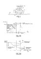
- Referring now to Figure 1, an
automotive vehicle 10 has a plurality ofwheels 12, two of which are shown as elevated above aroad plane 14. Aroll control system 16 is included withinvehicle 10. Theroll control system 16 is used to counteract the lifting ofwheels 12 fromroad plane 14 as will be further described below.Roll control system 16 includes aroll controller 18 that is preferably microprocessor based.Roll controller 18 may be part of a dynamic stability control system of theautomotive vehicle 10.Roll controller 18 is coupled to atorque control system 20 that is used to control the torque of thewheels 12. Althoughtorque control system 20 is illustrated as a separate item,torque control system 20 may be included inroll controller 18 which may in turn be included within a dynamic stability control system. Such a system may also have an antilock brake controller incorporated therein.Torque control system 20 may act in conjunction with the electronic engine controller, a driveline engagement mechanism or braking system, or a combination of these to control the torque at one or all of thewheels 12.Torque controller 20 androll controller 18 may be coupled towheel speed sensors 22 located at each of thewheels 12.Wheel speed sensors 22 provideroll controller 18 with a signal indicative of the speed of the individual wheel to which it is attached. Various types of wheel speed sensors including toothed-wheel type systems would be evident to those skilled in the art. -
Other sensors 24 may be coupled to rollcontrol system 16. For example, roll angle sensors, steering wheel angle sensors, yaw rate sensors, and other sensors may be incorporated therein.Other sensors 24, as will be further described below, may be used to identify a condition suitable for the potential of wheel lift. Such a condition may initiate further action byroll control system 16 to verify wheel lift. - In the following example, the application of brake pressure is used to provide the change in torque. However, other methods such as applying engine torque may also be used to change the amount of torque at a wheel. Further references to the application of torque to a wheel may include hydraulic or electric brake torque, changes in engine torque or engagement of driveline torque through the use of an electronically controlled transfer case, differential, transmission or clutch. The present invention may also be used to determine if a sensor has failed in the
roll control system 16. That is, if roll is suspected by a particular sensor, but all other conditions or sensors indicate otherwise, the sensor may be operating improperly. Also, although speed is used, wheel acceleration may also be used in place of speed as would be evident to those skilled in the art. - Referring now to Figure 2, in
step 30, if a roll sensor failure is suspected or in step 32 if wheel lift is suspected by theroll control system 16,block 34 initiates the wheel lift determination process. Instep 36, torque is applied to the wheel suspected of lifting and the wheel speed at the suspected wheel is stored. Instep 38 the torque is increased by applying a test pulse of torque to the suspected wheel. Torque is applied until a torque threshold (Torque_Max) is achieved. Instep 40, if the torque is greater than the Torque_Max, the torque is held constant instep 42. Instep 44, if the time as counted by the Build_Counter is greater than a predetermined time,step 46 is executed in which the torque is released and the wheel speed at the initiation of the release of torque is stored. Instep 44, if the counter is not greater than the predetermined hold time, the counter is incremented instep 48. Afterstep 48 the change in wheel speed is compared to a predetermined change in wheel speed. If the wheel speed change is not greater than a predetermined speed in step 50, steps 38-44 are again executed. If the wheel speed change is greater than a predetermined speed, this indicates a lifted wheel. In this case, step 52 is executed in which a wheel lift status flag is set. Afterstep 52,step 54 is executed in which the build counter is reset. - Referring back to step 40, if the torque is not greater than the torque threshold then step 50 is executed.
- Referring back to step 46, after the wheel speed is recorded after the torque release,
step 56 is executed. Instep 56 torque is released. Afterstep 56,step 58 is implemented in which the wheel speed change is compared to a reacceleration threshold. The reacceleration threshold is a predetermined value that corresponds to a wheel speed change that should be achieved should wheel contact be reestablished. The wheel speed change is determined from the time that the torque was released. If the wheel speed change is greater than a reacceleration threshold or if the wheel lift status fromstep 52 is zero, wheel contact is assumed. In such a case the traction level may be calculated instep 60. If the wheel speed does not increase over the reacceleration threshold, then the wheel lift status is confirmed beginning with step 70. - Referring back to step 58, if the wheel speed is less than the reacceleration threshold,
step 62 compares the Dump_Counter to a predetermined dump time. If the predetermined dump time is greater than the Dump_Counter, then the Dump_Counter is incremented instep 64 andsteps step 66 and the Dump_Counter is reset instep 68. Afterstep 68, the process is reinitiated and returns to step 36. - Returning back to step 60, the traction level is calculated in
step 60. Afterstep 60, the plausibility of a sensor failure is determined. If, for example, the process was initiated based on the suspicion of a sensor failure fromblock 30 above and no wheel lift was detected, a sensor failure is indicated in step 72. For either result, if a sensor failure is indicated by block 70 or not, the build counter and Dump_ Counter are cleared inblock 74 and the wheel lift status is cleared inblock 76. The end of the routine occurs in block 78. - Thus, as can be seen, the application of torque can be used to first determine whether a suspected wheel has lifted from the pavement. For confirmation, the removal of the torque and the resulting wheel speed change may be used to confirm the initial finding. Advantageously, the system may be implemented in a dynamic stability system of an automotive vehicle without adding further sensors. If rollover is detected, then the rollover can be corrected by applying the brakes or generating a steering correction.
- Referring now to Figure 3A,
various lines Lines step 42 above) until it is released. - Referring now to Figure 3B, a plot of wheel speed corresponding to the various times is illustrated. As shown, the wheel speed of a loaded wheel is illustrated by
line 96, which is higher than the wheel speed of a lifted wheel illustrated byline 98. - Referring now to Figure 4,
automotive vehicle 10 includeswheel speed sensors 22 that are coupled at eachwheel 12. Each wheel also has brakes that are hydraulically coupled to abrake system 104 throughhydraulic lines Hydraulic lines 106 are coupled to the front brakes and form a front brake circuit andhydraulic lines 108 are coupled to the rear brakes forming a rear brake circuit. Many vehicles are manufactured in such a configuration in which the front wheels and rear wheels are on different brake circuits.Brake system 104 may include an anti-lockbrake system controller 110. The anti-lockbrake system controller 110 is known in the art. The anti-lockbrake system controller 110 may be an integral part ofbrake system 104 or a separate component. The anti-lockbrake system controller 110 builds pressure in the wheels and in response thereto prevents the wheel from locking by releasing the brake pressure thereto. - A rollover stability control system controller 18' is coupled to
brake system 104. The rollover stability control system controller 18' may commandbrake system 104 to provide hydraulic pressure to a front wheel (or rear wheel) to prevent the vehicle from rolling over. - It is desirable to allow the roll stability control system to have the full capacity of the hydraulic brake actuation system during severe roll maneuvers. As described above, the wheel lift detection system may apply brakes to change the torque in a tire to detect whether a wheel is lifted. In the first embodiment of the invention, the wheel lift pressure request is suppressed on a wheel when there is a large pressure requested on the other wheel of the same hydraulic circuit. That is, when a large roll control pressure request is generated for the same hydraulic circuit, it is desirable to suppress the wheel lift pressure request.
- A
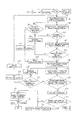
brake pedal 112 is also coupled tobrake system 104.Brake pedal 112 provides the system with an indication as to the amount of brake pressure desired by the vehicle operator. - Referring now to Figures 5A and 5B, in step 120 i is an array index that refers to each of the wheels of the vehicle. That is, each of the wheels of the vehicle is labeled 0 through 3 (LF, RF, LR, RR, respectively). The following method may be run simultaneously or sequentially on each of the wheels of the vehicle to determine whether the wheels have lifted. In the present example, the determination of whether a wheel has lifted is performed sequentially. i is initially 0 and is incremented in the following method. In
step 120 if i is less than 4,step 122 is executed. Instep 122 whether or not to run wheel lift detection is determined. As described above, the lift suspected flag is generated from the various sensors when the dynamics indicate that a wheel lift may be impending. Instep 122, if the conditions are not met to run lift detection,step 124 is executed in which the wheel lift operation is exited for that wheel. In step 126 a counter is incremented to proceed to the next wheel. - Referring back to step 122, if the conditions are not not valid (valid),
step 128 is executed. Instep 128 if lift detection was not run during thelast loop step 130 initializes the system for a build cycle. To initialize the system the flags and timers are initialized, caliper pressure is applied, and the wheel speeds are initialized. The system returns to step 126 afterstep 130. Instep 128 if the lift detection was run during the last execution loop,step 132 is executed. Instep 132 if the conditions require exit of lift detection instep 132,step 134 is executed after which step 126 is executed. Instep 132 if the conditions do not require exit of the lift condition,step 126 is executed without the exit process, so wheel lift will continue on that wheel in the next execution. - Referring back to step 120, if the wheel lift detection is run for each of the wheels (where i=4)
step 140 is executed in which the wheels are determined if they are in a lift detection mode. If no wheels are in a lift detection mode step 142 is executed in which the system is exited. Instep 140 if any of the wheels are in lift detection mode the counter i is checked instep 144. If the counter is not less than 4, step 142 is executed. If the counter is less than 4,step 146 is executed. Instep 146 if the system is in a lift detection operation with no drive torque applied,step 148 is executed. Instep 148 it is determined if the pressure request is large on the control wheel that is on the same hydraulic circuit as a lifted wheel. If this is the case,step 150 is executed in which the wheel lift pressure increase is inhibited for that wheel. That is, if the roll control system is trying to prevent rollover, the wheel lift pressure request is suppressed if a roll control pressure request is applied to a wheel on the same hydraulic circuit. When the request drops below a second threshold the wheel lift pressure request suppression may be discontinued. The suppression may also be discontinued during a stable roll motion. - Referring back to step 148, if the pressure request on the control wheel is not large on the same hydraulic circuit or the pressure increase is inhibited in
step 150, step 152 is executed in which the reacceleration reference velocity is updated. The reacceleration reference velocity is the wheel speed variable that is monitored throughout the entire execution of the wheel lift detection algorithm. It is equated to the wheel speed during deceleration. When the wheel speed increases, the reacceleration reference velocity is increased at a fixed rate that represents the minimum wheel acceleration that represents contact with the ground. Separate thresholds are used to compare the wheel acceleration to the reacceleration reference velocity during the build and release cycles. Instep 154 if the caliper pressure estimate is greater than the lift pressure request plus the threshold instep 154 and instep 156 if the driver is braking,step 158 is executed in which the initial wheel speed is set to the current wheel speed, the wheel lifted status is set to false and the ABS monitor active is set to true. - Referring back to
steps step 146 the system is not in a lift detection operation with no drive torque applied, or instep 154 if the caliper pressure estimate is not greater than the lift pressure request plus the threshold, or the driver is not braking instep 156, or afterstep 154, the system continues instep 160 to determine whether or not the lift build is active. If the lift build is active the build cycle is run instep 162. The build cycle will be further described below. After the build cycle is run,step 164 is executed in which the timers or flags are checked. If the timers or flags indicate an exit of a build cycle instep 164, step 166 is executed in which the possibly grounded flag is set if the exiting is due to the timing out of the build cycle. After 166,step 168 is executed in which the build active flag is cleared, the timers are reset, the caliper pressure is removed and the initial wheel speed is set to the current wheel speed. Instep 164 if the timers or flags do not indicate exit of the build cycle the wheel index is incremented instep 174 to runstep 144 on the next wheel. If the lift build is not active instep 160,step 170 is executed in which the release timers are checked. If the release timers are greater than 0 the release cycle is executed instep 172. The release cycle will be further described below. Afterstep 172step 174 is executed which increments the wheel counter. Afterstep 174,step 144 is executed. Referring back to step 170, if the release timers are not greater than 0 the system determines whether or not the ABS monitor flag is active instep 180. Instep 180 if the monitor flag is active the ABS monitor mode is run instep 182. After the ABS monitor is runstep 174 is executed. Instep 180 if the ABS monitor mode is not active thesystem step 174 is executed. - Referring now to Figures 6A and 6B, the build cycle from
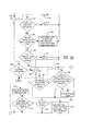
step 162 is described in further detail. A lift timer is decremented for each wheel while it is running in the build cycle. Instep 202 the lift timer for the wheel, if it is greater than 0, is decremented instep 204. If the lift timer is not greater than 0,step 206 is executed. If the lift pressure has been reached and is operating,step 208 is executed in which the build timer is again decremented. The Lift_Build_Timer monitors the length of time that the lift build pressure has been applied. - Referring back to step 206, if the lift build pressure is not reached or the lift build timer is equal to zero,
step 210 is performed. Instep 210 if the brake pressure estimate is greater than the lift pressure hold threshold then step 212 is executed in which the lift detect pressure is set to the lift pressure threshold and the lift pressure reached flag is set to true. Afterstep 212 and afterstep 208, or if the conditions instep 210 are not met,step 214 is executed in which it is determined whether or not the wheel velocity is increasing. If the wheel velocity is increasingstep 216 is executed in which the initial wheel speed is set to the wheel velocity and the initialized build timer is set to its maximum calibrated value. This allows the system to capture the maximum or peak wheel speed since the wheel speed may continue to rise for a short amount of time after the build cycle is initiated. - Referring back to step 214, if the wheel velocity is not increasing,
step 218 is executed in which the wheel deceleration is compared to a calibrated threshold. This may also be performed by determining a drop in wheel speed from the initial wheel speed and comparing it to a threshold. If the wheel deceleration (or drop in wheel speed) is greater than the calibrated threshold a possibly lifted wheel flag is set instep 220, the lifted on build flag is set instep 222, and instep 224 the end build cycle is performed. Afterstep 224,step 226 is executed in which the release cycle is entered. The release cycle will be further described below. - Referring back to step 218, if the wheel deceleration is not greater than the calibrated
threshold step 230 is executed in which the difference between the wheel speed and reacceleration reference velocity is compared to a second calibrated threshold. If the difference between the wheel speed and the reacceleration reference velocity does exceed a second calibrated threshold, an absolutely grounded flag is set instep 232, a lift_on_build signal is set to false instep 234. Instep 234 the lifted status flag is also set to false and the build cycle is ended instep 236. Afterstep 236 the release cycle is entered instep 226. - Referring back to step 230, if the difference between the wheel speed and reacceleration is not exceeding a second threshold,
step 238 is executed. Instep 238 the slip ratio of the wheel is determined. Instep 240, if the slip ratio is greater than a small negative value and the wheel speed is increasing and the target pressure has been reached for a specific time,step 242 is executed in which a possibly grounded flag is set and the build cycle is ended. Afterstep 242,step 226 is executed in which the release cycle is performed. - Referring back to step 240, if the slip ratio is not greater than a small negative value or the wheel speed is not increasing or the target pressure has not been reached for a specific time,
step 244 is executed. Instep 244 if the pressure increase inhibit is set or the lift not suspected flag is set and the pressure is less than half the target pressure,step 246 is executed in which the lift monitor flag is set to be active and the build cycle ends instep 248. Afterstep 148,step 226 enters the release cycle. - Referring back to step 244, if the target pressure is not less than half the target pressure or the pressure increase inhibit is set or the lift not suspected flag is set, then step 250 is executed in which the slip is determined. If there is a large
negative slip step 252 is executed in which the deep slip active flag is set and a lift monitor active flag is set. Thereafter, step 254 ends the build cycle and the release cycle is entered instep 226. Instep 250 if there are no large negative slips step 256 is executed in which the system returns to step 126 of Figure 5A. - Referring now to Figure 7A the release cycle is described in further detail. In
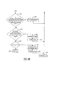
step 270 the build active flag is set to false and the build timer is cleared. Instep 272 the lift timer is reset and the release timer is also reset. Instep 274 the initial wheel speed is set to the current wheel speed. Instep 276 the caliper pressure is removed. It should be noted that steps 270-276 may correspond to step 168 and may only be run once in the first execution of a given period of successive operations of the release cycle. Steps 270-276 are run for each instance of End Build Cycle in Figures 6A and 6B (Step step 280. Instep 282 the lift timer is decremented and the release timer is also decremented. Instep 284 it is determined whether the wheel is decelerating. If the wheel is decelerating the initial wheel speed is set to the current wheel speed instep 286 and the release timer is reset instep 288. Instep 284 if the wheel is not decelerating and afterstep 288,step 290 is executed in which the wheel acceleration is compared to a calibration threshold. The wheel acceleration may also be determined as the difference between the wheel speed and reacceleration reference velocity. If the acceleration is greater than a calibration threshold,step 292 is executed in which an absolutely grounded flag is set. Instep 294 the flags are reset to false. Afterstep 294step 296 is executed in which the release active flag is set to false. - Referring back to step 290, if the acceleration is not greater than a calibrated threshold then step 300 is executed. In
step 300 if there is a small increase in wheel speed or the slip is greater than athreshold step 302 is executed in which a possibly grounded flag is set and the reset flag is set to false. Afterstep 302,step 296 is executed. - Referring back to step 300, if there is not a small increase in wheel speed or the slip is not greater than a threshold,
step 304 is executed. Instep 304 it is determined whether the system has lifted_on_build (during the build cycle) and the timer has expired. Instep 304 if the system was determined to be lifted_on_build and no reacceleration was performed before the timer expired,step 306 is executed in which the absolutely lifted flag is executed and the flags are set to true instep 308. - Referring back to step 304 and after
step 296,step 310 is executed. Instep 310 if there is pressure being applied by the driver or the brake system,step 312 is executed in which the lifted status flags are set to false and the release active flags are set to false instep 314. Instep 310 if there is no pressure being applied by the driver of the brake system or afterstep 314,step 316 is executed. Instep 316 if the lift monitor isactive step 318 is executed. Instep 318 if the lift suspected flag is set or the pressure increase inhibit is cleared,step 320 is executed in which it is determined whether the deep slip active is false. If the deep slip active flag is false, then step 322 exits the system. - Referring back to step 320 if the deep slip active is not
false step 324 is executed in which if the deep slip ratio is greater than a small negative threshold then step 326 is executed in which the deep slip active flag is reset to false. The system continues instep 322. Instep 324 if the slip ratio is not greater than a small negative threshold or instep 318 if the lift suspected flag is not set or the pressure increase inhibit is not cleared or instep 316 if the lift monitor flag is not active,step 328 is executed. Instep 328 if the lift timer is greater than 0 and the release timer is greater than 0 the system returns back to step 174 in Figure 5A through step 330. If the lift timer is not greater than 0 and the release timer is not greater than 0 then step 322 is executed. - Figure 8 describes the ABS Monitor mode operation. At the beginning of each cycle of the wheel lift detection routine, driver braking or the caliper pressure larger than a wheel lift request are checked, in
steps step 350 is executed in which it is determined whether or not the ABS is operating. Instep 350 if the ABS is operating,step 352 is executed in which an exit timer is set to a maximum value. The ABS timer is reset to its maximum value as long as ABS is active. If the ABS is not operating an exit timer is decremented instep 354. The ABS timer is decremented to cause an exit from ABS monitor mode at a fixed period of time after the end of ABS operation. The pressure from the drivers braking is used as the pressure build in ABS monitor mode. If the wheel is lifted the driver braking will cause a slip ratio that will result in an ABS pressure release. However, the wheel will continue to decelerate as long as it is off the ground. Aftersteps step 356 is executed in which the conditions are checked to determine whether ABS is operating and whether wheel lift is suspected. Instep 356 if all the conditions indicate ABS is operating and a wheel lift is suspectedstep 358 is executed. Instep 358 if the wheel speed has dropped by more than a calibrated threshold indicating wheel lift an absolutely lifted flag is set instep 360. Instep 358 if the conditions are not true then step 362 is executed in which it is determined whether the ABS timer is greater than 0. If the ABS timer is greater than 0step 364 is executed. The ABS timer is then decremented. - Referring back to step 362 if the ABS timer is not greater than 0 the ABS timer is reset to a maximum value in
step 366 and the initial wheel speed is set to the current wheel speed instep 368. - Referring back to step 356, if all the conditions indicate ABS is not operating or wheel lift is not suspected
step 370 is executed. Instep 370 the ABS timer is set to a maximum value and instep 372 the initial wheel speed is set to the current wheel speed. Aftersteps step 374 is executed in which the exit timer is compared to 0. If the exit timer is 0,step 376 is executed in which the ABS monitor flag is cleared and the system exits instep 378. Instep 374 if the exit timer is not 0 then the wheel acceleration is compared to the calibration amount. The wheel acceleration may be the wheel velocity increasing above a reacceleration reference velocity by more than a calibrated amount. Instep 380 if the wheel acceleration is greater than the acceleration amount then an absolutely grounded flag is set instep 382 and the reacceleration reference velocity is set equal to the wheel speed instep 384. Afterstep 384 the system returns back to the top level instep 386. That is, the system returns to step 174 of Figure 5A. - Referring back to step 380, if the wheel acceleration is not greater than the
calibration amount step 390 is executed. Instep 390 if the absolutely grounded flag is not set for that wheel,step 392 is executed. Instep 392 if a small negative slip is present and the wheel is acceleratingstep 394 generates a possibly grounded flag. Instep 392 if a small negative slip ratio is not present or the wheel is not acceleratingstep 386 is executed. - While particular embodiments of the invention have been shown and described, numerous variations alternate embodiments will occur to those skilled in the art. Accordingly, it is intended that the invention be limited only in terms of the appended claims.
Claims (12)
- A method of controlling an automotive vehicle (10) comprising:detecting a potential for a wheel lift;determining a wheel lift pressure request to determine wheel lift;generating a roll control pressure request; andsuppressing the wheel lift pressure request in response to the roll control pressure request.
- A method as recited in claim 1 wherein determining a wheel lift pressure request comprises determining a wheel lift pressure request to determine wheel lift for a first wheel on a hydraulic circuit.
- A method as recited in claim 2 wherein generating a roll control pressure request comprises generating a roll control pressure request to a second wheel of the hydraulic circuit and monitoring the difference between the roll control pressure request and the caliper pressure estimate for a control wheel so that the hydraulic circuit fulfills the roll control pressure request.
- A method as recited in claim 1 wherein the step of suppressing comprises suppressing the wheel lift pressure when the roll control caliper pressure request is above an estimate of the control caliper pressure by a predetermined threshold.
- A method as recited in claim 1 further comprising when the roll control pressure request is below a second threshold, discontinuing suppressing.
- A method as recited in claim 1 further comprising discontinue suppressing during a stable roll motion.
- A method as recited in claim 1 further comprising discontinue suppressing when the vehicle is grounded.
- A method of controlling a vehicle having a hydraulic circuit coupled to a first wheel and a second wheel comprising:initiating build request in response to a suspected wheel lift for the first wheel of the hydraulic circuit;generating a roll control pressure request for a second wheel of the hydraulic circuit; andentering a release cycle for the wheel lift pressure request when the roll control pressure request is above a predetermined threshold.
- A method as recited in claim 8 further comprising when the roll control pressure request is below a second threshold, discontinuing the release cycle.
- A method as recited in claim 9 further comprising initiating a build cycle after discontinuing the release cycle.
- A method of operating an automotive vehicle (10) comprising:initiating a build cycle;storing a peak wheel speed after initiating the build cycle;determining a second wheel speed to determine a change in wheel speed from the peak speed; anddetermining a wheel lift status when the change in the wheel speed is greater than a predetermined value.
- A method as recited in claim 11 further comprising determining a slip ratio in response to an applied pressure or torque.
Applications Claiming Priority (10)
| Application Number | Priority Date | Filing Date | Title |
|---|---|---|---|
| US40015602P | 2002-08-01 | 2002-08-01 | |
| US400156P | 2002-08-01 | ||
| US40130902P | 2002-08-05 | 2002-08-05 | |
| US40141802P | 2002-08-05 | 2002-08-05 | |
| US401309P | 2002-08-05 | ||
| US401418P | 2002-08-05 | ||
| US608909 | 2003-06-27 | ||
| US10/608,909 US7109856B2 (en) | 2000-09-25 | 2003-06-27 | Wheel lifted and grounded identification for an automotive vehicle |
| US604398 | 2003-07-17 | ||
| US10/604,398 US7302331B2 (en) | 2002-08-01 | 2003-07-17 | Wheel lift identification for an automotive vehicle |
Publications (2)
| Publication Number | Publication Date |
|---|---|
| EP1386804A1 true EP1386804A1 (en) | 2004-02-04 |
| EP1386804B1 EP1386804B1 (en) | 2009-03-18 |
Family
ID=30119458
Family Applications (1)
| Application Number | Title | Priority Date | Filing Date |
|---|---|---|---|
| EP03254816A Expired - Fee Related EP1386804B1 (en) | 2002-08-01 | 2003-07-31 | Wheel lift identification for an automotive vehicle |
Country Status (2)
| Country | Link |
|---|---|
| US (1) | US7302331B2 (en) |
| EP (1) | EP1386804B1 (en) |
Cited By (1)
| Publication number | Priority date | Publication date | Assignee | Title |
|---|---|---|---|---|
| FR2946602A1 (en) * | 2009-06-15 | 2010-12-17 | Bosch Gmbh Robert | METHOD FOR CONTROLLING A BRAKING SYSTEM |
Families Citing this family (20)
| Publication number | Priority date | Publication date | Assignee | Title |
|---|---|---|---|---|
| US20050033549A1 (en) * | 2003-07-25 | 2005-02-10 | Siemens Vdo Automotive Corporation | Rollover sensing using tire pressure sensor |
| JP4251100B2 (en) * | 2004-03-25 | 2009-04-08 | 三菱ふそうトラック・バス株式会社 | Rollover suppression control device for vehicle |
| US7191047B2 (en) * | 2004-09-27 | 2007-03-13 | Delphi Technologies, Inc. | Motor vehicle control using a dynamic feedforward approach |
| US7239952B2 (en) * | 2004-12-08 | 2007-07-03 | Continental Teves, Inc. | Reduced order parameter identification for vehicle rollover control system |
| US7557697B2 (en) * | 2005-02-22 | 2009-07-07 | Continental Teves, Inc. | System to measure wheel liftoff |
| US8359146B2 (en) * | 2005-12-15 | 2013-01-22 | Bendix Commercial Vehicle Systems Llc | Single channel roll stability system |
| US8191975B2 (en) * | 2005-12-15 | 2012-06-05 | Bendix Commercial Vehicle Systems Llc | Single channel roll stability system |
| JP4792979B2 (en) * | 2006-01-11 | 2011-10-12 | 株式会社アドヴィックス | Vehicle motion control device |
| WO2007086104A1 (en) * | 2006-01-24 | 2007-08-02 | Bosch Corporation | Brake control method and device for two-wheeled motor vehicle |
| DE602006018366D1 (en) * | 2006-01-24 | 2010-12-30 | Bayerische Motoren Werke Ag | BRAKE CONTROL METHOD AND DEVICE |
| CN101336181B (en) | 2006-01-27 | 2012-06-13 | 博世株式会社 | Brake control method of motor bicycle and apparatus thereof |
| CN101336182A (en) * | 2006-01-31 | 2008-12-31 | 博世株式会社 | Brake control method of motor bicycle and apparatus thereof |
| JP5014163B2 (en) | 2006-02-08 | 2012-08-29 | ボッシュ株式会社 | Brake control method and brake control apparatus for motorcycle |
| GB2454223B (en) * | 2007-11-01 | 2011-09-21 | Haldex Brake Products Ltd | Vehicle stability control method |
| US7894958B2 (en) * | 2008-02-11 | 2011-02-22 | Caterpillar Inc | Traction control system |
| EP2138367B1 (en) * | 2008-06-26 | 2015-05-13 | Kawasaki Jukogyo Kabushiki Kaisha | Slip suppression control system for vehicle |
| US8700260B2 (en) | 2009-03-30 | 2014-04-15 | Lord Corporation | Land vehicles and systems with controllable suspension systems |
| DE102013012992A1 (en) * | 2013-08-02 | 2015-02-05 | Wabco Gmbh | Method and vehicle dynamics control device for determining critical lateral acceleration values of a motor vehicle |
| US10466217B1 (en) | 2013-12-23 | 2019-11-05 | Aclima Inc. | Method to combine partially aggregated sensor data in a distributed sensor system |
| GB2587217B (en) * | 2019-09-18 | 2023-10-11 | Haldex Brake Prod Ab | A method of adjustment during stability control of a vehicle |
Citations (4)
| Publication number | Priority date | Publication date | Assignee | Title |
|---|---|---|---|---|
| US6272420B1 (en) * | 1997-11-22 | 2001-08-07 | Robert Bosch Gmbh | Method and device for detecting motor vehicle tilt |
| US20010037677A1 (en) * | 2000-04-05 | 2001-11-08 | Hans Holst | Process to prevent the overturning of a vehicle around its longitudinal axis |
| US6356188B1 (en) * | 2000-09-25 | 2002-03-12 | Ford Global Technologies, Inc. | Wheel lift identification for an automotive vehicle |
| DE10046036A1 (en) * | 2000-09-18 | 2002-03-28 | Knorr Bremse Systeme | Method for estimating the risk of a vehicle tipping over |
Family Cites Families (146)
| Publication number | Priority date | Publication date | Assignee | Title |
|---|---|---|---|---|
| US2917126A (en) | 1957-04-04 | 1959-12-15 | Nolan Phillips | Driving control safety mechanism for tractors |
| US3604273A (en) | 1968-11-25 | 1971-09-14 | Aviat Electric Ltd | Angular rate sensor |
| US3608925A (en) | 1969-05-07 | 1971-09-28 | Peter H Murphy | Apparatus for offsetting centrifugal force affecting motor vehicles |
| US3899028A (en) | 1972-03-30 | 1975-08-12 | Systron Donner Corp | Angular position sensing and control system, apparatus and method |
| US4023864A (en) * | 1973-09-20 | 1977-05-17 | Lang Davis Industries, Inc. | Automatic stability control system with strain gauge sensors |
| US3972543A (en) | 1974-12-06 | 1976-08-03 | The Bendix Corporation | Combination vehicle yaw stabilizer |
| US3948567A (en) * | 1975-02-12 | 1976-04-06 | The Bendix Corporation | Sway control means for a trailer |
| USRE30550E (en) * | 1975-11-06 | 1981-03-24 | Durrell U. Howard | Automatic trailer sway sensing and brake applying system |
| JPS6015015B2 (en) | 1979-06-29 | 1985-04-17 | 株式会社 レオ技研 | Road moisture detection device |
| JPS58152793A (en) | 1982-03-05 | 1983-09-10 | ティー・シー・エム株式会社 | Device for preventing turning-sideways of transport car |
| JPS60163770A (en) * | 1984-02-02 | 1985-08-26 | Honda Motor Co Ltd | Steering device for vehicle |
| US4592565A (en) * | 1984-10-17 | 1986-06-03 | Leo Eagle | Apparatus for detecting an overturning moment in a moving vehicle, and jackknifing in a trailer-truck combination |
| JPH06104455B2 (en) * | 1985-03-15 | 1994-12-21 | 日産自動車株式会社 | Vehicle motion condition estimation device |
| US4650212A (en) * | 1985-03-20 | 1987-03-17 | Mazda Motor Corporation | Vehicle suspension system |
| EP0198450B1 (en) | 1985-04-13 | 1988-12-21 | Nissan Motor Co., Ltd. | Vehicle control system for controlling side slip angle and yaw rate gain |
| JP2532059B2 (en) * | 1985-09-13 | 1996-09-11 | 日産自動車株式会社 | Vehicle suspension control device |
| JPH0629039B2 (en) | 1986-01-10 | 1994-04-20 | 日産自動車株式会社 | Vehicle motion state estimation device |
| DE3606797C2 (en) * | 1986-03-01 | 2000-11-23 | Bosch Gmbh Robert | Device and method for controlling, in particular for limiting, the driving speed of a road vehicle |
| US4761022A (en) | 1986-03-08 | 1988-08-02 | Toyota Jidosha Kabushiki Kaisha | Suspension controller for improved turning |
| JPH0694253B2 (en) | 1986-03-17 | 1994-11-24 | トヨタ自動車株式会社 | Roll control device for vehicle |
| JPH0829649B2 (en) | 1987-03-31 | 1996-03-27 | 日産自動車株式会社 | Active suspension device |
| DE3821610A1 (en) | 1988-06-27 | 1989-12-28 | Bayerische Motoren Werke Ag | CONTROL DEVICE FOR STABILIZING A VEHICLE |
| JPS6432918A (en) * | 1987-07-28 | 1989-02-02 | Mitsubishi Motors Corp | Active suspension controller |
| DE3826982C2 (en) * | 1987-08-10 | 2000-11-30 | Denso Corp | Auxiliary steering system connected to an anti-lock control system for use in motor vehicles |
| DE3877118T2 (en) | 1987-10-15 | 1993-07-01 | Mazda Motor | DEVICE FOR DETERMINING THE FRICTION FACTOR FOR VEHICLES. |
| JPH01122716A (en) | 1987-11-05 | 1989-05-16 | Hitachi Ltd | Active suspension control system for automobile |
| DE3738221A1 (en) | 1987-11-11 | 1989-06-08 | Bayerische Motoren Werke Ag | METHOD AND DEVICE FOR DETECTING THE STATE OF A ROAD |
| JP2618250B2 (en) | 1987-12-22 | 1997-06-11 | 富士重工業株式会社 | Traction control device |
| DE3804587A1 (en) | 1988-02-13 | 1989-08-24 | Daimler Benz Ag | ADDITIONAL STEERING |
| DE3805589A1 (en) | 1988-02-23 | 1989-08-31 | Lucas Ind Plc | METHOD AND DEVICE FOR CONTROLLING A BRAKE SYSTEM FOR HEAVY VEHICLES |
| US4898431A (en) * | 1988-06-15 | 1990-02-06 | Aisin Seiki Kabushiki Kaisha | Brake controlling system |
| US5313389A (en) | 1988-09-13 | 1994-05-17 | Aisin Seiki Kabushiki Kaisha | Fail-safe mechanism for vehicle stability augmentation steering system |
| JP2768710B2 (en) * | 1988-09-17 | 1998-06-25 | ローベルト・ボッシュ・ゲゼルシャフト・ミット・ベシュレンクテル・ハフツング | A device that activates a protection device that protects a vehicle occupant |
| JP2565384B2 (en) * | 1988-09-30 | 1996-12-18 | 富士重工業株式会社 | Control device for automobile active suspension |
| GB8825540D0 (en) | 1988-11-01 | 1988-12-07 | Jaguar Cars | Air bag restraint systems |
| JPH0732331Y2 (en) * | 1989-01-18 | 1995-07-26 | 日産自動車株式会社 | Vehicle steering control device |
| US4998593A (en) * | 1989-03-31 | 1991-03-12 | Aisin Seiki Kabushiki Kaisha | Steering and brake controlling system |
| US5239868A (en) | 1989-05-19 | 1993-08-31 | Matsushita Electric Industrial Co., Ltd. | Angular rate detecting device |
| JP2000344085A (en) * | 1999-06-03 | 2000-12-12 | Toyota Motor Corp | Device for displaying wheel controlled condition |
| JP2867448B2 (en) * | 1989-08-11 | 1999-03-08 | 株式会社日立製作所 | Active suspension control device |
| JPH0396468A (en) * | 1989-09-07 | 1991-04-22 | Honda Motor Co Ltd | Estimation method for fore and aft acceleration and deceleration of body |
| JPH0833408B2 (en) | 1990-03-29 | 1996-03-29 | 株式会社日立製作所 | Angle detection device, translational acceleration detection device, and vehicle control device |
| DE4112638A1 (en) | 1990-04-20 | 1991-10-24 | Mazda Motor | DEVICE FOR CONTROLLING THE TORQUE DISTRIBUTION FOR ALL-WHEEL DRIVE VEHICLES |
| JP2762711B2 (en) * | 1990-07-02 | 1998-06-04 | 日産自動車株式会社 | Vehicle braking behavior compensator |
| JP2600986B2 (en) | 1990-07-06 | 1997-04-16 | 三菱自動車工業株式会社 | Rear wheel steering control method |
| JP2679415B2 (en) * | 1990-12-21 | 1997-11-19 | 日産自動車株式会社 | Vehicle braking force left / right distribution control device |
| US5408411A (en) * | 1991-01-18 | 1995-04-18 | Hitachi, Ltd. | System for predicting behavior of automotive vehicle and for controlling vehicular behavior based thereon |
| DE4121954A1 (en) * | 1991-07-03 | 1993-01-07 | Bosch Gmbh Robert | METHOD FOR OBTAINING THE YEAR SPEED AND / OR THE LATERAL SPEED |
| US5282134A (en) * | 1991-08-19 | 1994-01-25 | Automotive Systems Laboratory, Inc. | Slant transform/signal space crash discriminator |
| US5324102A (en) * | 1991-10-18 | 1994-06-28 | Fag Kugelfischer Georg Schafer Kgaa | Method and apparatus for regulating the braking force of motorcycles |
| US5335176A (en) | 1991-12-02 | 1994-08-02 | Koyo Seiko Co., Ltd. | Safety system for vehicles |
| JP3197330B2 (en) * | 1992-04-10 | 2001-08-13 | 本田技研工業株式会社 | Vehicle driving force control device |
| US5548536A (en) | 1992-05-16 | 1996-08-20 | Daimler-Benz Ag | Method for determining quantities which characterize the driving behavior |
| DE4226746C1 (en) | 1992-08-13 | 1993-10-07 | Daimler Benz Ag | Method for determining a driving-dependent steering angle |
| DE4228893B4 (en) * | 1992-08-29 | 2004-04-08 | Robert Bosch Gmbh | System for influencing the driving dynamics of a motor vehicle |
| US5278761A (en) * | 1992-11-12 | 1994-01-11 | Ford Motor Company | Method for vehicular wheel spin control that adapts to different road traction characteristics |
| JP2882232B2 (en) | 1993-03-17 | 1999-04-12 | 三菱自動車工業株式会社 | Vehicle weight center slip angle measuring device |
| JP3303500B2 (en) * | 1994-02-02 | 2002-07-22 | トヨタ自動車株式会社 | Vehicle behavior control device |
| DE4405379A1 (en) * | 1994-02-19 | 1995-08-24 | Bosch Gmbh Robert | ABS braking system for vehicle |
| KR950028978A (en) * | 1994-04-06 | 1995-11-22 | 전성원 | Shift pattern control device and method for steep slope and steep curve |
| KR100207106B1 (en) | 1994-04-06 | 1999-07-15 | 정몽규 | Method and apparatus of taper for automobile testing road |
| US5446658A (en) | 1994-06-22 | 1995-08-29 | General Motors Corporation | Method and apparatus for estimating incline and bank angles of a road surface |
| JP3116738B2 (en) * | 1994-07-28 | 2000-12-11 | トヨタ自動車株式会社 | Vehicle behavior control device |
| US5610575A (en) * | 1994-08-25 | 1997-03-11 | Automotive Systems Laboratory, Inc. | Method and system for detecting vehicle roll-over |
| US5602734A (en) * | 1994-09-23 | 1997-02-11 | Advanced Safety Concepts, Inc. | Automobile air bag systems |
| JP3050061B2 (en) * | 1994-10-25 | 2000-06-05 | トヨタ自動車株式会社 | Occupant restraint |
| US5732379A (en) * | 1994-11-25 | 1998-03-24 | Itt Automotive Europe Gmbh | Brake system for a motor vehicle with yaw moment control |
| US5732378A (en) * | 1994-11-25 | 1998-03-24 | Itt Automotive Europe Gmbh | Method for determining a wheel brake pressure |
| DE19515054A1 (en) | 1994-11-25 | 1996-05-30 | Teves Gmbh Alfred | Regulating travel stability of vehicle using input variable converted in yawing variable |
| US5732377A (en) * | 1994-11-25 | 1998-03-24 | Itt Automotive Europe Gmbh | Process for controlling driving stability with a yaw rate sensor equipped with two lateral acceleration meters |
| US5549328A (en) | 1995-01-17 | 1996-08-27 | Gabriel Ride Control Products, Inc. | Roll control system |
| JPH08258588A (en) | 1995-03-27 | 1996-10-08 | Mazda Motor Corp | Road surface condition detecting device in vehicle |
| JP3463415B2 (en) | 1995-06-22 | 2003-11-05 | 日産自動車株式会社 | Vehicle yawing behavior control device |
| US5648903A (en) * | 1995-07-10 | 1997-07-15 | Ford Global Technologies, Inc. | Four wheel steering control utilizing front/rear tire longitudinal slip difference |
| FI108084B (en) | 1995-09-08 | 2001-11-15 | Vaisala Oyj | Method and apparatus for measuring road surface characteristics |
| JP3248411B2 (en) * | 1995-10-11 | 2002-01-21 | トヨタ自動車株式会社 | Vehicle behavior control device |
| JP3248413B2 (en) * | 1995-10-18 | 2002-01-21 | トヨタ自動車株式会社 | Vehicle behavior control device |
| JP3008833B2 (en) | 1995-10-25 | 2000-02-14 | トヨタ自動車株式会社 | Estimation device for vehicle body skidding speed |
| JP3627325B2 (en) * | 1995-11-17 | 2005-03-09 | アイシン精機株式会社 | Vehicle motion control device |
| JP3533420B2 (en) | 1995-12-05 | 2004-05-31 | トヨタ自動車株式会社 | Brake control device |
| DE19602879C1 (en) * | 1996-01-29 | 1997-08-07 | Knorr Bremse Systeme | Method for detecting the risk of a vehicle tipping over |
| AUPN786796A0 (en) * | 1996-02-05 | 1996-02-29 | Verward Pty Ltd (trading as Brooks Merchants) | Vehicle seat |
| DE19609717A1 (en) * | 1996-03-13 | 1997-09-18 | Bosch Gmbh Robert | Arrangement for detecting rollover processes in vehicles |
| US5787375A (en) * | 1996-04-01 | 1998-07-28 | Ford Global Technologies, Inc. | Method for determining steering position of automotive steering mechanism |
| US5742919A (en) * | 1996-04-26 | 1998-04-21 | Ford Global Technologies, Inc. | Method and apparatus for dynamically determining a lateral velocity of a motor vehicle |
| US5809434A (en) | 1996-04-26 | 1998-09-15 | Ford Global Technologies, Inc. | Method and apparatus for dynamically determically determining an operating state of a motor vehicle |
| US5742918A (en) * | 1996-04-26 | 1998-04-21 | Ford Global Technologies, Inc. | Method and apparatus for dynamically compensating a lateral acceleration of a motor vehicle |
| JPH09315277A (en) * | 1996-05-31 | 1997-12-09 | Unisia Jecs Corp | Device for controlling movement of vehicle |
| US5707117A (en) * | 1996-07-19 | 1998-01-13 | General Motors Corporation | Active brake control diagnostic |
| DE19634728C1 (en) | 1996-08-28 | 1998-04-02 | Daimler Benz Ag | Vehicle steering |
| US5878357A (en) * | 1996-09-03 | 1999-03-02 | Ford Global Technologies, Inc. | Method and apparatus for vehicle yaw rate estimation |
| US5720533A (en) * | 1996-10-15 | 1998-02-24 | General Motors Corporation | Brake control system |
| JPH10119743A (en) * | 1996-10-23 | 1998-05-12 | Aisin Seiki Co Ltd | Motion control device for vehicle |
| JPH10129439A (en) | 1996-10-25 | 1998-05-19 | Aisin Seiki Co Ltd | Motion controlling device for vehicle |
| US5723782A (en) * | 1996-11-29 | 1998-03-03 | Bolles, Jr.; Robert C. | Method of land vehicle suspension evaluation and design through roll angle analysis |
| DE19650691C2 (en) | 1996-12-07 | 1998-10-29 | Deutsch Zentr Luft & Raumfahrt | Method for steering assistance for a driver of a road vehicle |
| US5825284A (en) | 1996-12-10 | 1998-10-20 | Rollover Operations, Llc | System and method for the detection of vehicle rollover conditions |
| US5736939A (en) * | 1996-12-11 | 1998-04-07 | Caterpillar Inc. | Apparatus and method for determing a condition of a road |
| GB9626045D0 (en) * | 1996-12-14 | 1997-01-29 | Rover Group | A vehicle roll stabilising system |
| JP3493568B2 (en) * | 1997-02-12 | 2004-02-03 | 光洋精工株式会社 | Car steering system |
| US6226579B1 (en) * | 1997-03-22 | 2001-05-01 | Robert Bosch Gmbh | Method and apparatus for operating a steering system for a motor vehicle |
| US6186267B1 (en) * | 1997-03-22 | 2001-02-13 | Robert Bosch Gmbh | Method and apparatus for operating a steering system for a motor vehicle |
| JP3269421B2 (en) * | 1997-04-04 | 2002-03-25 | 三菱自動車工業株式会社 | Automatic vehicle deceleration control device |
| PT991543E (en) * | 1997-07-01 | 2004-10-29 | Dynamotive L L C | ANTI-ROTATING BRAKING SYSTEM |
| US6026926A (en) * | 1997-07-25 | 2000-02-22 | Honda Giken Kogyo Kabushiki Kaisha | Electric power steering apparatus |
| JPH11194091A (en) * | 1997-08-20 | 1999-07-21 | Daimler Benz Ag | Determining method of road surface condition and implementation apparatus thereof |
| DE19744085A1 (en) * | 1997-10-06 | 1999-04-08 | Bosch Gmbh Robert | System producing trigger signal for vehicle safety unit with collision with low obstacle |
| DE19751935A1 (en) * | 1997-11-22 | 1999-05-27 | Bosch Gmbh Robert | Method and device for determining a quantity describing the center of gravity of a vehicle |
| EP1040033B1 (en) * | 1997-12-16 | 2005-04-06 | Continental Teves AG & Co. oHG | Method for improving tilt stability in a motor vehicle |
| EP1040035B1 (en) * | 1997-12-16 | 2007-03-14 | Continental Teves AG & Co. oHG | Method and device for limiting transversal acceleration in a motor vehicle |
| DE19802041A1 (en) * | 1998-01-21 | 1999-07-22 | Bosch Gmbh Robert | Procedure for stabilizing car to avoid tipping over, especially for about axis oriented in car's longitudinal direction |
| GB9801780D0 (en) * | 1998-01-29 | 1998-03-25 | Rover Group | A roll damper arrangement |
| US5971503A (en) | 1998-02-03 | 1999-10-26 | Ford Global Technologies, Inc. | Hydraulic control unit with ambient temperature compensation during fluid pressure delivery |
| US6002974A (en) * | 1998-02-06 | 1999-12-14 | Delco Electronics Corporation | Vehicle rollover sensing using extended kalman filter |
| US6038495A (en) * | 1998-02-06 | 2000-03-14 | Delco Electronics Corporation | Vehicle rollover sensing using short-term integration |
| US6002975A (en) | 1998-02-06 | 1999-12-14 | Delco Electronics Corporation | Vehicle rollover sensing |
| DE19812237C1 (en) * | 1998-03-20 | 1999-09-23 | Daimler Chrysler Ag | Method for driving dynamics control on a road vehicle |
| US5946644A (en) | 1998-03-30 | 1999-08-31 | Chrysler Corporation | Steering center indicator device |
| GB9812274D0 (en) * | 1998-06-09 | 1998-08-05 | Rover Group | Hydraulic control systems |
| US6050360A (en) * | 1998-06-24 | 2000-04-18 | General Motors Corporation | Apparatus and method for producing a desired return torque in a vehicle power steering system having a rotational steering position sensor |
| US6198988B1 (en) * | 1998-08-10 | 2001-03-06 | Ford Global Technologies, Inc. | Method for detecting an erroneous direction of travel signal |
| US6073065A (en) * | 1998-09-04 | 2000-06-06 | Ford Global Technologies, Inc. | Method for detecting a bank angle experienced by a moving vehicle |
| US6169939B1 (en) * | 1998-09-08 | 2001-01-02 | Ford Global Technologies, Inc. | Method of generating a vehicle lateral acceleration signal for use in an active tilt control system |
| JP3497746B2 (en) * | 1998-10-26 | 2004-02-16 | 本田技研工業株式会社 | Electric power steering device |
| US6179394B1 (en) * | 1998-11-09 | 2001-01-30 | General Motors Corporation | Active brake balance control method |
| US6062336A (en) * | 1998-11-13 | 2000-05-16 | General Motors Corporation | Adaptive variable effort power steering system |
| US6195606B1 (en) * | 1998-12-07 | 2001-02-27 | General Motors Corporation | Vehicle active brake control with bank angle compensation |
| US6202009B1 (en) * | 1998-12-22 | 2001-03-13 | Ford Global Technologies, Inc. | Method for detecting fault of vehicle motion sensors |
| US6185485B1 (en) * | 1998-12-22 | 2001-02-06 | Ford Global Technologies, Inc | Relative vehicle platform having synchronized adaptive offset calibration for lateral accelerometer and steering angle sensor |
| JP2000198453A (en) * | 1998-12-29 | 2000-07-18 | Robert Bosch Gmbh | Steer-by-wire steering system for vehicle |
| JP3726557B2 (en) * | 1999-05-26 | 2005-12-14 | トヨタ自動車株式会社 | Roll suppression control device for vehicle |
| US6202020B1 (en) * | 1999-08-20 | 2001-03-13 | Meritor Heavy Vehicle Systems, Llc | Method and system for determining condition of road |
| US6233510B1 (en) * | 1999-10-15 | 2001-05-15 | Meritor Heavy Vehicle Technology, Llc | Method and system for predicting road profile |
| US6263261B1 (en) * | 1999-12-21 | 2001-07-17 | Ford Global Technologies, Inc. | Roll over stability control for an automotive vehicle |
| DE10000550B4 (en) * | 2000-01-08 | 2005-09-15 | Bayerische Motoren Werke Ag | Device for detecting flashovers in a vehicle |
| JP4169948B2 (en) * | 2000-05-11 | 2008-10-22 | ボッシュ株式会社 | Method for detecting rear wheel lift of motorcycle and brake control method |
| JP4396002B2 (en) * | 2000-06-27 | 2010-01-13 | トヨタ自動車株式会社 | Vehicle traction control device |
| JP3960740B2 (en) * | 2000-07-31 | 2007-08-15 | トヨタ自動車株式会社 | Brake control device for vehicle |
| US6397127B1 (en) * | 2000-09-25 | 2002-05-28 | Ford Global Technologies, Inc. | Steering actuated wheel lift identification for an automotive vehicle |
| JP2002107371A (en) * | 2000-09-29 | 2002-04-10 | Toyota Motor Corp | Rotating state detecting device for wheel |
| JP2002104149A (en) * | 2000-09-29 | 2002-04-10 | Toyota Motor Corp | Rotating state detecting device for wheel |
| US7063334B2 (en) * | 2000-11-22 | 2006-06-20 | Howard Tak Su Lim | Vehicle stability system using active tilting mechanism |
| JP3736340B2 (en) * | 2000-12-14 | 2006-01-18 | トヨタ自動車株式会社 | Vehicle control device |
| US6351694B1 (en) * | 2001-01-16 | 2002-02-26 | Ford Global Technologies, Inc. | Method for robust estimation of road bank angle |
| US6556908B1 (en) * | 2002-03-04 | 2003-04-29 | Ford Global Technologies, Inc. | Attitude sensing system for an automotive vehicle relative to the road |
| US6741922B2 (en) * | 2002-05-30 | 2004-05-25 | Bendix Commercial Vehicle Systems Llc | Antilock braking system based roll over prevention |
-
2003
- 2003-07-17 US US10/604,398 patent/US7302331B2/en active Active
- 2003-07-31 EP EP03254816A patent/EP1386804B1/en not_active Expired - Fee Related
Patent Citations (4)
| Publication number | Priority date | Publication date | Assignee | Title |
|---|---|---|---|---|
| US6272420B1 (en) * | 1997-11-22 | 2001-08-07 | Robert Bosch Gmbh | Method and device for detecting motor vehicle tilt |
| US20010037677A1 (en) * | 2000-04-05 | 2001-11-08 | Hans Holst | Process to prevent the overturning of a vehicle around its longitudinal axis |
| DE10046036A1 (en) * | 2000-09-18 | 2002-03-28 | Knorr Bremse Systeme | Method for estimating the risk of a vehicle tipping over |
| US6356188B1 (en) * | 2000-09-25 | 2002-03-12 | Ford Global Technologies, Inc. | Wheel lift identification for an automotive vehicle |
Cited By (2)
| Publication number | Priority date | Publication date | Assignee | Title |
|---|---|---|---|---|
| FR2946602A1 (en) * | 2009-06-15 | 2010-12-17 | Bosch Gmbh Robert | METHOD FOR CONTROLLING A BRAKING SYSTEM |
| EP2266853A1 (en) | 2009-06-15 | 2010-12-29 | Robert Bosch GmbH | Control method for a braking system |
Also Published As
| Publication number | Publication date |
|---|---|
| US7302331B2 (en) | 2007-11-27 |
| EP1386804B1 (en) | 2009-03-18 |
| US20040111208A1 (en) | 2004-06-10 |
Similar Documents
| Publication | Publication Date | Title |
|---|---|---|
| US7302331B2 (en) | Wheel lift identification for an automotive vehicle | |
| US6356188B1 (en) | Wheel lift identification for an automotive vehicle | |
| JP4119244B2 (en) | How to control running stability | |
| US7132937B2 (en) | Wheel lift identification for an automotive vehicle using passive and active detection | |
| US7233236B2 (en) | Passive wheel lift identification for an automotive vehicle using operating input torque to wheel | |
| US7881850B2 (en) | Wheel lifted and grounded identification for an automotive vehicle | |
| EP1386805B1 (en) | Method for dynamically determining the wheel grounding and wheel lifting conditions and their applications in roll stability control | |
| US7109856B2 (en) | Wheel lifted and grounded identification for an automotive vehicle | |
| US7653471B2 (en) | Active driven wheel lift identification for an automotive vehicle | |
| JP3480929B2 (en) | Vehicle motion control device | |
| US9162656B2 (en) | Active driven wheel lift identification for an automotive vehicle | |
| JP4319799B2 (en) | Fall prevention device and method | |
| US20070164608A1 (en) | Method and apparatus for deactivating a hillholder function | |
| JP2007513002A (en) | Method and apparatus for stabilizing a vehicle in a dangerous driving situation | |
| EP2214939B1 (en) | Vehicle stability control method | |
| US5551769A (en) | Method and system for split mu control for anti-lock brake systems | |
| GB2353573A (en) | Adjusting the braking action at the wheels of a motor vehicle | |
| WO2017153797A1 (en) | A method of adjusting an estimated value of the height of the gravity center of a vehicle | |
| JP4729830B2 (en) | Vehicle control device | |
| JP3295972B2 (en) | Anti-skid control device |
Legal Events
| Date | Code | Title | Description |
|---|---|---|---|
| PUAI | Public reference made under article 153(3) epc to a published international application that has entered the european phase |
Free format text: ORIGINAL CODE: 0009012 |
|
| AK | Designated contracting states |
Kind code of ref document: A1 Designated state(s): AT BE BG CH CY CZ DE DK EE ES FI FR GB GR HU IE IT LI LU MC NL PT RO SE SI SK TR |
|
| AX | Request for extension of the european patent |
Extension state: AL LT LV MK |
|
| 17P | Request for examination filed |
Effective date: 20040713 |
|
| AKX | Designation fees paid |
Designated state(s): DE FR GB SE |
|
| 17Q | First examination report despatched |
Effective date: 20050502 |
|
| RAP1 | Party data changed (applicant data changed or rights of an application transferred) |
Owner name: FORD GLOBAL TECHNOLOGIES, LLC. |
|
| 17Q | First examination report despatched |
Effective date: 20050502 |
|
| GRAP | Despatch of communication of intention to grant a patent |
Free format text: ORIGINAL CODE: EPIDOSNIGR1 |
|
| GRAS | Grant fee paid |
Free format text: ORIGINAL CODE: EPIDOSNIGR3 |
|
| GRAA | (expected) grant |
Free format text: ORIGINAL CODE: 0009210 |
|
| AK | Designated contracting states |
Kind code of ref document: B1 Designated state(s): DE FR GB SE |
|
| REG | Reference to a national code |
Ref country code: GB Ref legal event code: FG4D |
|
| REF | Corresponds to: |
Ref document number: 60326677 Country of ref document: DE Date of ref document: 20090430 Kind code of ref document: P |
|
| REG | Reference to a national code |
Ref country code: SE Ref legal event code: TRGR |
|
| PLBE | No opposition filed within time limit |
Free format text: ORIGINAL CODE: 0009261 |
|
| STAA | Information on the status of an ep patent application or granted ep patent |
Free format text: STATUS: NO OPPOSITION FILED WITHIN TIME LIMIT |
|
| 26N | No opposition filed |
Effective date: 20091221 |
|
| PGFP | Annual fee paid to national office [announced via postgrant information from national office to epo] |
Ref country code: SE Payment date: 20110203 Year of fee payment: 8 Ref country code: FR Payment date: 20110217 Year of fee payment: 8 |
|
| REG | Reference to a national code |
Ref country code: SE Ref legal event code: EUG |
|
| REG | Reference to a national code |
Ref country code: FR Ref legal event code: ST Effective date: 20120330 |
|
| PG25 | Lapsed in a contracting state [announced via postgrant information from national office to epo] |
Ref country code: FR Free format text: LAPSE BECAUSE OF NON-PAYMENT OF DUE FEES Effective date: 20110801 |
|
| PG25 | Lapsed in a contracting state [announced via postgrant information from national office to epo] |
Ref country code: SE Free format text: LAPSE BECAUSE OF NON-PAYMENT OF DUE FEES Effective date: 20110801 |
|
| PGFP | Annual fee paid to national office [announced via postgrant information from national office to epo] |
Ref country code: DE Payment date: 20180618 Year of fee payment: 16 Ref country code: GB Payment date: 20180625 Year of fee payment: 16 |
|
| REG | Reference to a national code |
Ref country code: DE Ref legal event code: R119 Ref document number: 60326677 Country of ref document: DE |
|
| GBPC | Gb: european patent ceased through non-payment of renewal fee |
Effective date: 20190731 |
|
| PG25 | Lapsed in a contracting state [announced via postgrant information from national office to epo] |
Ref country code: DE Free format text: LAPSE BECAUSE OF NON-PAYMENT OF DUE FEES Effective date: 20200201 Ref country code: GB Free format text: LAPSE BECAUSE OF NON-PAYMENT OF DUE FEES Effective date: 20190731 |