EP1387924B1 - Apparatus and methods for tubular makeup interlock - Google Patents
Apparatus and methods for tubular makeup interlock Download PDFInfo
- Publication number
- EP1387924B1 EP1387924B1 EP02722498A EP02722498A EP1387924B1 EP 1387924 B1 EP1387924 B1 EP 1387924B1 EP 02722498 A EP02722498 A EP 02722498A EP 02722498 A EP02722498 A EP 02722498A EP 1387924 B1 EP1387924 B1 EP 1387924B1
- Authority
- EP
- European Patent Office
- Prior art keywords
- tubular
- spider
- top drive
- controller
- tubular string
- Prior art date
- Legal status (The legal status is an assumption and is not a legal conclusion. Google has not performed a legal analysis and makes no representation as to the accuracy of the status listed.)
- Expired - Lifetime
Links
- 238000000034 method Methods 0.000 title claims description 41
- 241000239290 Araneae Species 0.000 claims description 119
- 238000004891 communication Methods 0.000 claims description 7
- 230000015572 biosynthetic process Effects 0.000 claims 5
- 230000001419 dependent effect Effects 0.000 claims 5
- 230000004888 barrier function Effects 0.000 claims 2
- 230000008878 coupling Effects 0.000 claims 1
- 238000010168 coupling process Methods 0.000 claims 1
- 238000005859 coupling reaction Methods 0.000 claims 1
- 239000012530 fluid Substances 0.000 description 17
- 238000005553 drilling Methods 0.000 description 12
- 230000006870 function Effects 0.000 description 4
- 230000000717 retained effect Effects 0.000 description 2
- 238000010276 construction Methods 0.000 description 1
- 238000003780 insertion Methods 0.000 description 1
- 230000037431 insertion Effects 0.000 description 1
- 230000007257 malfunction Effects 0.000 description 1
- 230000007935 neutral effect Effects 0.000 description 1
- 230000000246 remedial effect Effects 0.000 description 1
Images


Classifications
-
- E—FIXED CONSTRUCTIONS
- E21—EARTH DRILLING; MINING
- E21B—EARTH DRILLING, e.g. DEEP DRILLING; OBTAINING OIL, GAS, WATER, SOLUBLE OR MELTABLE MATERIALS OR A SLURRY OF MINERALS FROM WELLS
- E21B19/00—Handling rods, casings, tubes or the like outside the borehole, e.g. in the derrick; Apparatus for feeding the rods or cables
- E21B19/16—Connecting or disconnecting pipe couplings or joints
- E21B19/165—Control or monitoring arrangements therefor
-
- E—FIXED CONSTRUCTIONS
- E21—EARTH DRILLING; MINING
- E21B—EARTH DRILLING, e.g. DEEP DRILLING; OBTAINING OIL, GAS, WATER, SOLUBLE OR MELTABLE MATERIALS OR A SLURRY OF MINERALS FROM WELLS
- E21B19/00—Handling rods, casings, tubes or the like outside the borehole, e.g. in the derrick; Apparatus for feeding the rods or cables
- E21B19/16—Connecting or disconnecting pipe couplings or joints
-
- E—FIXED CONSTRUCTIONS
- E21—EARTH DRILLING; MINING
- E21B—EARTH DRILLING, e.g. DEEP DRILLING; OBTAINING OIL, GAS, WATER, SOLUBLE OR MELTABLE MATERIALS OR A SLURRY OF MINERALS FROM WELLS
- E21B41/00—Equipment or details not covered by groups E21B15/00 - E21B40/00
- E21B41/0021—Safety devices, e.g. for preventing small objects from falling into the borehole
-
- E—FIXED CONSTRUCTIONS
- E21—EARTH DRILLING; MINING
- E21B—EARTH DRILLING, e.g. DEEP DRILLING; OBTAINING OIL, GAS, WATER, SOLUBLE OR MELTABLE MATERIALS OR A SLURRY OF MINERALS FROM WELLS
- E21B44/00—Automatic control systems specially adapted for drilling operations, i.e. self-operating systems which function to carry out or modify a drilling operation without intervention of a human operator, e.g. computer-controlled drilling systems; Systems specially adapted for monitoring a plurality of drilling variables or conditions
Definitions
- Figure 6 is a flow chart illustrating the use of an interlock system of the present invention with a spider and a top drive and Figure 7 illustrates the mechanics of the interlock system in use with a spider, a top drive and a controller.
- a tubular string 210 is retained in a closed spider 400 and prevented from moving in a downward direction.
- the spider includes a spider piston sensor located at a spider piston 420 to sense when the spider 400 is open or closed around the tubular string 210.
- the sensor data 502 is relayed to a controller 900.
- a compensator 270 may be utilized to gather additional information about the joint formed between the tubular and the tubular string.
- the compensator 270 in addition to allowing incremental movement of the top drive 200 during threading together of the tubulars, may be used to ensure that a threaded joint has been made and that the tubulars are mechanically connected together. For example, after a joint has been made between the tubular and the tubular string, the top drive may be raised or pulled up. If a joint has been formed between the tubular and the string, the compensator will "stoke out" completely, due the weight of the tubular string therebelow.
- the spider 400 is not required to be unlocked and opened.
- the spider 400 and the slips 410 are constructed and arranged to prevent downward movement of the string but allow the tubular string 210 to be lifted up and moved axially in a vertical direction even though the spider is closed. When closed, the spider 400 will not allow the tubular string 210 to fall through its slips 410 due to friction and the shaped of the teeth on the spider slips.
- the rod 664 is retracted allowing the control plate 650 to move freely from the first to a second position.
- the sensor assembly 660 can also be used with the top drive 200 as well in the same fashion.
- hydraulic fluid is supplied to a top drive piston 370 via a top drive control valve 642 and hydraulic lines.
- the top drive control valve 642 is also a three-way valve and is operated by a top drive lever 640.
- a pump 610 is used to circulate fluid to the respective pistons 370, 420.
- a reservoir 620 is used to re-circulate hydraulic fluid and receive excess fluid. Excess gas in the reservoir 620 is vented 622.
- the interlock system may be any interlock system that allows a set of slips to disengage only when another set of slips is engaged to the tubular.
- the interlock system may be mechanically, electrically, hydraulically, pneumatically actuated systems.
- the spider may be any spider that functions to hold a tubular or a tubular string at the surface of the wellbore.
- a top drive may be any system that can grab a tubular by the inner or outer surface and can rotate the tubular. The top drive can also be hydraulically or pneumatically activated.
Description
- The present invention relates to an apparatus and methods for facilitating the connection of tubulars. More particularly, the invention relates to an interlock system for a top drive and a spider for use in assembling or disassembling tubulars.
- In the construction and completion of oil or gas wells, a drilling rig is constructed on the earth's surface to facilitate the insertion and removal of tubular strings into a wellbore. The drilling rig includes a platform and power tools such as an elevator and a spider to engage, assemble, and lower the tubulars into the wellbore. The elevator is suspended above the platform by a draw works that can raise or lower the elevator in relation to the floor of the rig. The spider is mounted in the platform floor. The elevator and spider both have slips that are capable of engaging and releasing a tubular, and are designed to work in tandem. Generally, the spider holds a tubular or tubular string that extends into the wellbore from the platform. The elevator engages a new tubular and aligns it over the tubular being held by the spider. A power tong and a spinner are then used to thread the upper and lower tubulars together. Once the tubulars are joined, the spider disengages the tubular string and the elevator lowers the tubular string through the spider until the elevator and spider are at a predetermined distance from each other. The spider then re-engages the tubular string and the elevator disengages the string and repeats the process. This sequence applies to assembling tubulars for the purpose of drilling, running casing or running wellbore components into the well. The sequence can be reversed to disassemble the tubular string.
- During the drilling of a wellbore, a drill string is made up and is then necessarily rotated in order to drill. Historically, a drilling platform includes a rotary table and a gear to turn the table. In operation, the drill string is lowered by an elevator into the rotary table and held in place by a spider. A Kelly is then threaded to the string and the rotary table is rotated, causing the Kelly and the drill string to rotate. After thirty feet (9 m) or so of drilling, the Kelly and a section of the string are lifted out of the wellbore, and additional drill string is added.
- The process of drilling with a Kelly is expensive due to the amount of time required to remove the Kelly, add drill string, reengage the Kelly, and rotate the drill string. In order to address these problems, top drives were developed.
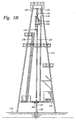
- Figure 1A is a side view of an upper portion of a
drilling rig 100 having atop drive 200 and anelevator 120. An upper end of a stack oftubulars 130 is shown on therig 100. The figure shows theelevator 120 engaged with a tubular 130. The tubular 130 is placed in position below thetop drive 200 by theelevator 120 in order for the top drive with its gripping means to engage the tubular. - Figure 1B is a side view of a
drilling rig 100 having atop drive 200, anelevator 120, and aspider 400. Therig 100 is built at thesurface 170 of the well. Therig 100 includes atravelling block 110 that is suspended bywires 150 fromdraw works 105 and holds thetop drive 200. Thetop drive 200 has a gripping means for engaging the inner wall of tubular 130 and amotor 240 to rotate the tubular 130. Themotor 240 rotates and threads the tubular 130 into thetubular string 210 extending into thewellbore 180. Themotor 240 can also rotate a drill string having a drill bit at an end, or for any other purposes requiring rotational movement of a tubular or a tubular string. Additionally, thetop drive 200 is shown withelevator 120 and arailing system 140 coupled thereto. Therailing system 140 prevents thetop drive 200 from rotational movement during rotation of thetubular string 210, but allows for vertical movement of the top drive under thetravelling block 110. - In Figure 1B, the
top drive 200 is shown engaged to tubular 130. The tubular 130 is positioned above thetubular string 210 located therebelow. With the tubular 130 positioned over thetubular string 210, thetop drive 200 can lower and thread the tubular into the tubular string. Additionally, thespider 400, disposed in theplatform 160, is shown engaged around atubular string 210 that extends intowellbore 180. - Figure 2 illustrates a side view of a top drive engaged to a tubular, which has been lowered through a spider. As depicted in the Figure, the
elevator 120 and thetop drive 200 are connected to thetravelling block 110 via acompensator 270. Thecompensator 270 functions similar to a spring to compensate for vertical movement of thetop drive 200 during threading of the tubular 130 to thetubular string 210. In addition to itsmotor 240, the top drive includes acounter 250 to measure rotation of the tubular 130 during the time tubular 130 is threaded totubular string 210. Thetop drive 200 also includes atorque sub 260 to measure the amount of torque placed on the threaded connection between the tubular 130 and thetubular string 210. Thecounter 250 and thetorque sub 260 transmit data about the threaded joint to a controller via data lines (not shown). The controller is preprogrammed with acceptable values for rotation and torque for a particular joint. The controller compares the rotation and the torque data to the stored acceptable values. - Figure 2 also illustrates a
spider 400 disposed in theplatform 160. Thespider 400 comprises aslip assembly 440, including a set ofslips 410, andpiston 420. Theslips 410 are wedge-shaped and are constructed and arranged to slidably move along a slopped inner wall of theslip assembly 440. Theslips 410 are raised or lowered bypiston 420. When theslips 410 are in the lowered position, they close around the outer surface of thetubular string 210. The weight of thetubular string 210 and the resulting friction between thetubular string 210 and theslips 410, forces the slips downward and inward, thereby tightening the grip on the tubular string. When theslips 410 are in the raised position as shown, the slips are opened and thetubular string 210 is free to move axially in relation to the slips. - Figure 3 is cross-sectional view of a
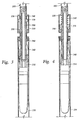
top drive 200 and a tubular 130. Thetop drive 200 includes a gripping means having acylindrical body 300, awedge lock assembly 350, andslips 340 with teeth (not shown). Thewedge lock assembly 350 and theslips 340 are disposed around the outer surface of thecylindrical body 300. The slips are constructed and arranged to mechanically grip the inside of the tubular 130. Theslips 340 are threaded topiston 370 located in ahydraulic cylinder 310. The piston is actuated by pressurized hydraulic fluid injected throughfluid ports springs 360 are located in thehydraulic cylinder 310 and are shown in a compressed state. When thepiston 370 is actuated, the springs decompress and assist the piston in moving theslips 340. Thewedge lock assembly 350 is constructed and arranged to force the slips against the inner wall of the tubular 130 and moves with thecylindrical body 300. - In operation, the
slips 340, and thewedge lock assembly 350 oftop drive 200 are lowered inside tubular 130. Once theslips 340 are in the desired position within the tubular 130, pressurized fluid is injected into the piston throughfluid port 320. The fluid actuates thepiston 370, which forces theslips 340 towards thewedge lock assembly 350. Thewedge lock assembly 350 functions to bias theslips 340 outwardly as the slips are slidably forced along the outer surface of the assembly, thereby forcing the slips to engage the inner wall of the tubular 130. - Figure 4 illustrates a cross-sectional view of a
top drive 200 engaged to a tubular 130. The figure showsslips 340 engaged with the inner wall of the tubular 130 and aspring 360 in the decompressed state. In the event of a hydraulic fluid failure, thesprings 360 can bias thepiston 370 to keep theslips 340 in the engaged position, thereby providing an additional safety feature to prevent inadvertent release of thetubular string 210. Once theslips 340 are engaged with the tubular 130, thetop drive 200 can be raised along with thecylindrical body 300. By raising thebody 300, thewedge lock assembly 350 will further bias theslips 340. With the tubular 130 engaged by thetop drive 200, the top drive can be relocated to align and thread the tubular withtubular string 210. - In another embodiment (not shown), a
top drive 200 includes a gripping means for engaging a tubular on the outer surface. For example, the slips can be arranged to grip on the outer surface of the tubular, preferably gripping under thecollar 380 of the tubular 130. In operation, the top drive is positioned over the desired tubular. The slips are then lowered by the top drive to engage thecollar 380 of the tubular 130. Once the slips are positioned beneath thecollar 380, the piston is actuated to cause the slips to grip the outer surface of the tubular 130. Sensors may be placed in the slips to ensure that proper engagement of the tubular. - Figure 5 is a flow chart illustrating a typical operation of a string or casing assembly using a top drive and a spider. The flow chart relates to the operation of an apparatus generally illustrated in Figure 1B. At a
first step 500, atubular string 210 is retained in aclosed spider 400 and is thereby prevented from moving in a downward direction. Atstep 510,top drive 200 is moved to engage a tubular 130 from a stack with the aid of anelevator 120. The tubular 130 may be a single tubular or could typically be made up of two or three tubulars threaded together to form a stack. Engagement of the tubular by the top drive includes grasping the tubular and engaging the inner surface thereof. Atstep 520, thetop drive 200 moves the tubular 130 into position above thetubular string 210. Atstep 530, thetop drive 200 threads the tubular 130 totubular string 210. Atstep 540, thespider 400 is opened and disengages thetubular string 210. Atstep 550, thetop drive 200 lowers thetubular string 210, including tubular 130 through the openedspider 400. Atstep 560 and thespider 400 is closed around thetubular string 210. Atstep 570 thetop drive 200 disengages the tubular string and can proceed to add another tubular 130 to thetubular string 210 as instep 510. The above-described steps may be utilized in running drill string in a drilling operation or in running casing to reinforce the wellbore or for assembling strings to place wellbore components in the wellbore. The steps may also be reversed in order to disassemble the casing or tubular string. - Although the top drive is a good alternative to the Kelly and rotary table, the possibility of inadvertently dropping a tubular string into the wellbore exists. As noted above, a top drive and spider must work in tandem, that is, at least one of them must engage the tubular string at any given time during tubular assembly. Typically, an operator located on the platform controls the top drive and the spider with manually operated levers that control fluid power to the slips that cause the top drive and spider to retain a tubular string. At any given time, an operator can inadvertently drop the tubular string by moving the wrong lever. Conventional interlocking systems have been developed and used with elevator/spider systems to address this problem, but there remains a need for a workable interlock system usable with a top drive/spider system such as the one described herein.
- There is a need therefore, for an interlock system for use with a top drive and spider to prevent inadvertent release of a tubular string. There is a further need for an interlock system to prevent the inadvertent dropping of a tubular or tubular string into a wellbore. There is also a need for an interlock system that prevents a spider or a top drive from disengaging a tubular string until the other component has engaged the tubular.
- WO01/59253 and WO00/52297 disclose a technique according to the preamble of claim 1 of this application.
- One or more aspects of the invention is / are set out in the independent claim(s).
- There is disclosed herein an apparatus for use with tubulars, comprising a first device for gripping and joining the tubulars; a second device for gripping the tubulars; and an interlock system to ensure that a tubular string is gripped by at least the first or second device.
- There is also disclosed herein an apparatus and methods to prevent inadvertent release of a tubular or tubular string. In one aspect, the apparatus and methods disclosed herein ensure that either the top drive or the spider is engaged to the tubular before the other component is disengaged from the tubular. The interlock system is utilized with a spider and a top drive during assembly of a tubular string.
- Some preferred embodiments of the invention will now be described by way of example only and with reference to the accompanying drawings, in which:
- Figure 1A is a side view of a drilling rig having a top drive and an elevator;
- Figure 1B is a side view of a drilling rig having a top drive, an elevator, and a spider;
- Figure 2 illustrates a side view of a top drive engaged to a tubular, which has been lowered through a spider;
- Figure 3 is cross-sectional view of a top drive and a tubular;
- Figure 4 illustrates a cross-sectional view of the top drive of Figure 3 engaged to a tubular;
- Figure 5 is a flow chart of a typical operation of tubular string or casing assembly using a top drive and a spider;
- Figure 6 shows a flow chart using an interlock system for a spider and a top drive;
- Figure 7 illustrates the mechanics of the interlock system in use with a spider, a top drive and a controller; and
- Figure 8 illustrates a control plate for a spider lever and a top drive lever.
- The present invention is an interlock system for use with a top drive and a spider during assembly of a string of tubulars. The invention may be utilized to assemble tubulars for different purposes including drill strings, strings of liner and casing and run-in strings for wellbore components.
- Figure 6 is a flow chart illustrating the use of an interlock system of the present invention with a spider and a top drive and Figure 7 illustrates the mechanics of the interlock system in use with a spider, a top drive and a controller. At
step 500, atubular string 210 is retained in aclosed spider 400 and prevented from moving in a downward direction. The spider includes a spider piston sensor located at aspider piston 420 to sense when thespider 400 is open or closed around thetubular string 210. Thesensor data 502 is relayed to acontroller 900. - A controller includes a programmable central processing unit that is operable with a memory, a mass storage device, an input control unit, and a display unit. Additionally, the controller includes well-known support circuits such as power supplies, clocks, cache, input/output circuits and the like. The controller is capable of receiving data from sensors and other devices and capable of controlling devices connected to it.
- One of the functions of the
controller 900 is to prevent opening of the spider. Preferably, thespider 400 is locked in the closed position by a solenoid valve 980 (Figure 7) that is placed in the control line between the manually operated spider control lever 630 (Figure 7) and the source of fluid power operating the spider. Specifically, the spider solenoid valve 980 controls the flow of fluid to thespider piston 420. The solenoid valve 980 is operated by thecontroller 900 and the controller is programmed to keep the valve closed until certain conditions are met. While valve 980 is electrically powered in the embodiment described herein, the valve could be fluidly or pneumatically powered so long as it is controllable by thecontroller 900. Typically, the valve 980 is closed and thespider 400 is locked until a tubular is successfully joined to the string and held by the top drive. - At
step 510, thetop drive 200 is moved to engage a pre-assembled tubular 130 from a stack with the aid of anelevator 120. A top drive sensor 995 (Fig. 7) is placed near atop drive piston 370 to sense when thetop drive 200 is disengaged, or in this case engaged around the tubular 130. Thesensor data 512 is relayed to thecontroller 900. Atstep 520, thetop drive 200 moves the tubular 130 into position and alignment above thetubular string 210. Atstep 530, thetop drive 200 rotationally engages the tubular 130 totubular string 210, creating a threaded joint therebetween.Torque data 532 from atorque sub 260 androtation data 534 from acounter 250 are sent to thecontroller 900. - The
controller 900 is preprogrammed with acceptable values for rotation and torque for a particular connection. Thecontroller 900 compares therotation data 534 and thetorque data 532 from the actual connections and determines if they are within the accepted values. If not, then thespider 400 remains locked and closed, and the tubular 130 can be rethreaded or some other remedial action can take place by sending a signal to an operator. If the values are acceptable, thecontroller 900 locks thetop drive 200 in the engaged position via a top drive solenoid valve 970 (Fig. 7) that prevents manual control of thetop drive 200. Atstep 540, thecontroller 900 unlocks thespider 400 via the spider solenoid valve, and allows fluid to power thepiston 420 to open thespider 400 and disengage it from thetubular string 210. Atstep 550, thetop drive 200 lowers thetubular string 210, including tubular 130 through the openedspider 400. Atstep 560 and thespider 400 is closed around thetubular string 210. The spider sensor 990 (Fig. 7) signals thecontroller 900 that thespider 400 is closed. If no signal is received, then thetop drive 200 stays locked and engaged totubular string 210. If a signal is received confirming that the spider is closed, the controller locks thespider 400 in the closed position, and unlocks thetop drive 200. Atstep 570 thetop drive 200 can disengage thetubular string 210 and proceed to add another tubular 130. In this manner, at least the top drive or the spider is engaging the tubular string at all times. - Alternatively, or in addition to the foregoing, a compensator 270 (shown in Figure 2) may be utilized to gather additional information about the joint formed between the tubular and the tubular string. The
compensator 270, in addition to allowing incremental movement of thetop drive 200 during threading together of the tubulars, may be used to ensure that a threaded joint has been made and that the tubulars are mechanically connected together. For example, after a joint has been made between the tubular and the tubular string, the top drive may be raised or pulled up. If a joint has been formed between the tubular and the string, the compensator will "stoke out" completely, due the weight of the tubular string therebelow. If however, a joint has not been formed between the tubular and the string due to some malfunction of the top drive or misalignment between a tubular and a tubular string therebelow, the compensator will stroke out only a partial amount due to the relatively little weight applied thereto by the single tubular or tubular stack. A stretch sensor located adjacent the compensator, can sense the stretching of thecompensator 270 and can relay the data to acontroller 900. Once thecontroller 900 processes the data and confirms that the top drive is engaged to a complete tubular string, thetop drive 200 is locked in the engaged position, and thenext step 540 can proceed. If no signal is received, then thespider 400 remains locked and a signal maybe transmitted by the controller to an operator. During this "stretching" step, thespider 400 is not required to be unlocked and opened. Thespider 400 and theslips 410 are constructed and arranged to prevent downward movement of the string but allow thetubular string 210 to be lifted up and moved axially in a vertical direction even though the spider is closed. When closed, thespider 400 will not allow thetubular string 210 to fall through itsslips 410 due to friction and the shaped of the teeth on the spider slips. - The
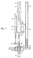
interlock system 500 is illustrated in Figure 7 with thespider 400, thetop drive 200, and thecontroller 900 including various control, signal, hydraulic, and sensor lines. Thetop drive 200 is shown engaged to atubular string 210 and is coupled to arailing system 140. The railing system includeswheels 142 allowing the top drive to move axially. Thespider 400 is shown disposed in theplatform 160 and in the closed position around thetubular string 210. Thespider 400 and thetop drive 200 may be pneumatically actuated, however the spider and top drive discussed herein are hydraulically activated. Hydraulic fluid is supplied to aspider piston 420 via aspider control valve 632. Thespider control valve 632 is a three-way valve and is operated by aspider lever 630. - Also shown in Figure 7 is a
sensor assembly 690 with apiston 692 coupled to spider slips 410 to detect when thespider 400 is open or closed. Thesensor assembly 690 is in communication with a lockingassembly 660, which along with acontrol plate 650 prevents the movement of the spider and top drive lever. The lockingassembly 660 includes apiston 662 having arod 664 at a first end. The rod 564 when extended, blocks the movement of thecontrol plate 550 when the plate is in a first position. When thespider 400 is in the open position, thesensor assembly 690 communicates to the lockingassembly 660 to move therod 664 to block the control plate's 650 movement. When thespider 400 is in the closed position as shown, therod 664 is retracted allowing thecontrol plate 650 to move freely from the first to a second position. Additionally, thesensor assembly 660 can also be used with thetop drive 200 as well in the same fashion. Similarly, hydraulic fluid is supplied to atop drive piston 370 via a top drive control valve 642 and hydraulic lines. The top drive control valve 642 is also a three-way valve and is operated by atop drive lever 640. Apump 610 is used to circulate fluid to therespective pistons reservoir 620 is used to re-circulate hydraulic fluid and receive excess fluid. Excess gas in thereservoir 620 is vented 622. - Further shown in Figure 7,
controller 900 collects data from atop drive sensor 995 regarding the engagement of the top drive to thetubular string 210. Data regarding the position of thespider 400 is also provided tocontroller 900 from aspider sensor 990. Thecontroller 900 controls fluid power to thetop drive 200 andspider 400 viasolenoid valves 970, 980, respectively. - In Figure 7, the
top drive 200 is engaged totubular string 210 while thespider 400 is in the closed position around the sametubular string 210. At this point, steps 500, 510, 520, and 530 of Figure 6 have occurred. Additionally, thecontroller 900 has determined through the data received fromcounter 250 andtorque sub 260 that an acceptable threaded joint has been made betweentubular 130 andtubular string 210. In the alternative or in addition to the foregoing, acompensator 270 can also provide data to thecontroller 900 that a threaded joint has been made and that the tubular 130 and thetubular string 210 are mechanically connected together via a stretch sensor (not shown). Thecontroller 900 then sends a signal to asolenoid valve 970 to lock and keep atop drive piston 370 in the engaged position within thetubular string 210. Moving to step 540 (figure 6), thecontroller 900 can unlock the previously lockedspider 400, by sending a signal to a solenoid valve 980. Thespider 400 must be unlocked and opened in order for thetop drive 200 to lower thetubular string 210 through thespider 400 and into a wellbore. An operator (not shown) can actuate aspider lever 630 that controls aspider valve 632, to allow thespider 400 to open and disengage thetubular string 210. When thespider lever 630 is actuated, the spider valve allows fluid to be flow tospider piston 420 causing spider slips 410 to open. With thespider 400 opened, asensor assembly 690 in communication with a lockingassembly 660 will cause arod 664 to block the movement of acontrol plate 650. Because theplate 650 will be blocked in the rightmost position, thetop drive lever 640 is held in the locked position and will be unable to move to the open position. - As illustrated in Figure 7, the interlock system when used with the top drive and the spider prevents the operator from inadvertently dropping the tubular string into the wellbore. As disclosed herein, the tubular string at all times is either engaged by the top drive or the spider. Additionally, the controller prevents operation of the top drive under certain, even if the top drive control lever is actuated. Further, the interlock system provides a control plate to control the physical movement of levers between an open and closed, thereby preventing the operator from inadvertently actuating the wrong lever.
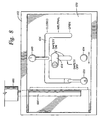
- Figure 8 illustrates a control plate for a spider lever and a top drive lever that can be used with the interlock system of the present invention. The
control plate 650 is generally rectangular in shape and is provided with a series ofslots 656 to control the movement of thespider lever 630, and thetop drive lever 640. Typically, thecontrol plate 650 is slideably mounted within abox 652. Theslots 656 define the various positions in which thelevers levers control plate 650 can be moved from a first rightmost position to a second leftmost position with aknob 654. However, bothlevers control plate 650 is shown in the first rightmost position with arod 664 extending from a lockingassembly 660 to block the movement of the control plate. In operation, in the first rightmost position of thecontrol plate 650, thespider lever 630 can be moved between the open and close positions, while thetop drive lever 640 is kept in the closed position. In the second leftmost position, thetop drive lever 640 can be moved between the open and close positions, while thespider lever 630 is kept in the closed position. Asafety lock 658 is provided to allow the top drive orspider levers control plate 650 when needed. - The interlock system may be any interlock system that allows a set of slips to disengage only when another set of slips is engaged to the tubular. The interlock system may be mechanically, electrically, hydraulically, pneumatically actuated systems. The spider may be any spider that functions to hold a tubular or a tubular string at the surface of the wellbore. A top drive may be any system that can grab a tubular by the inner or outer surface and can rotate the tubular. The top drive can also be hydraulically or pneumatically activated.
- While the foregoing is directed to the preferred embodiment of the present invention, other and further embodiments of the invention may be devised without departing from the basic scope thereof, and the scope thereof is determined by the claims that follow.
Claims (57)
- An apparatus for use with tubulars, comprising:a first device for gripping and joining the tubulars; anda second device for gripping the tubulars;characterised by an interlock system to ensure that a tubular string is gripped by at least the first or second device.
- An apparatus as claimed in claim 1, wherein the first device comprises a top drive disposable on a rig above the second device.
- An apparatus as claimed in claim 2, wherein the top drive comprises:a body having a slip assembly disposed on a surface;the slip assembly engageable on a surface of a first end of a tubular;a motor to provide rotational movement to the tubulars; anda compensator disposed on the top drive thereby allowing incremental axial movement of the tubular.
- An apparatus as claimed in claim 2 or 3, wherein the second device is a spider having a set of slips therein for engaging the tubulars.
- An apparatus as claimed in claim 4, wherein the interlock system prevents the top drive from disengaging the tubular string, unless the spider is engaged around the tubular string.
- An apparatus as claimed in claim 4 or 5, wherein the interlock system prevents the spider from disengaging the tubular string, unless the top drive is engaged to the tubular string.
- An apparatus as claimed in claim 4, 5 or 6, wherein the interlock system further comprises a controller.
- An apparatus as claimed in claim 7, wherein the controller collects data relating to a joint formed between the tubulars.
- An apparatus as claimed in claim 8 wherein data is generated by a torque sub disposed adjacent the top drive.
- An apparatus as claimed in claim 8 or 9, wherein data is generated by a revolution counter.
- An apparatus as claimed in claim 8, 9 or 10, wherein the data relates to torque generated in the joint.
- An apparatus as claimed in claim 8, 9, 10 or 11, wherein the data further relates to the number of tubular rotations making up the joint.
- An apparatus as claimed in any of claims 8 to 12, wherein the controller compares the data to pre-stored values defining an acceptable joint.
- An apparatus as claimed in any of claims 8 to 13, wherein data is generated from the compensator, the data related to the axial movement of the compensator during make up of the joint.
- An apparatus as claimed in any of claims 8 to 14, wherein the interlock system further includes at least one valve to enable and lock out controls for the top drive and the spider, the valve controllable by the controller based upon the data.
- An apparatus as claimed in any of claims 4 to 15, wherein the interlock system further comprises:a physical barrier to control the movement of manual controls controlling the top drive and the spider to engage and release the tubular string; anda sensor assembly in communication with the spider and a locking assembly, the sensor assembly arranged to sense the engagement of the spider and relay the information to the locking assembly, which is arranged to control the movement of the physical barrier.
- An apparatus as claimed in claim 1, wherein the apparatus is for assembling and disassembling tubulars, wherein:the first device has a motor for rotating and joining tubulars at a joint and forming a tubular string therefrom, and a cylindrical body having a first set of slips and a wedge lock assembly disposed on the cylindrical body, the first set of slips being coupled to a piston that is coupled to a resilient member;and wherein the second device has a piston coupled to a second set of slips.
- An apparatus as claimed in claim 17, wherein the first set of slips is engageable with an inner surface of the tubulars.
- An apparatus as claimed in claim 17, wherein the first set of slips is engageable with an outer surface of the tubulars.
- An apparatus as claimed in claim 17, 18 or 19, wherein a first member sensor is coupled to the first device and a second member sensor is coupled to the second device.
- An apparatus as claimed in any of claims 17 to 20, wherein the first device further comprises:a counter providing data relating to the tubular rotations making up the joint;a torque sub providing data relating to the amount of torque placed during joining of the tubulars; anda compensator coupling the first device to a rig and providing data regarding whether the first device is engaging the tubular string.
- An apparatus as claimed in any of claims 17 to 21, wherein the first device is a top drive and is couplable to a railing system mounted on a rig.
- An apparatus as claimed in any of claims 17 to 22, wherein the second device is couplable to a platform of a rig.
- An apparatus as claimed in any of claims 17 to 23, wherein the second device is a spider.
- An apparatus as claimed in claim 21 as dependent from claim 20, wherein the interlock system further comprises:a sensor assembly in communication with the second set of slips;a locking assembly in communication with the sensor assembly;a control plate having a first member lever controlling a first member valve, a second member lever controlling a second member valve, the movement of the control plate is controlled by the locking assembly; anda controller in communication with the first and second member sensors, the torque sub, the counter, a first and second member solenoid valves.
- An apparatus as claimed in claim 25, wherein the controller is also in communication with the compensator.
- A method for use with assembling and dissembling tubulars comprising:joining a first tubular engaged by a first apparatus to a second tubular engaged by a second apparatus thereby forming a tubular string;opening the second apparatus thereby disengaging the string;lowering the tubular string;engaging the second apparatus to the string; anddisengaging the first apparatus from the string;characterised by providing an interlock system to ensure that at least the first apparatus or the second apparatus is engaging the tubular string.
- A method as claimed in claim 27, wherein the first apparatus further comprises a motor for joining the tubulars and at least a first set of slips, and the second apparatus has at least a second set of slips.
- A method as claimed in claim 28, wherein the first set of slips are engageable with an inner surface of the tubular.
- A method as claimed in claim 28 or 29, wherein the first set of slips are engageable with an outer surface of the tubular.
- A method as claimed in any of claims 28 to 30, wherein the interlock system is arranged to prevent the first set of slips from disengaging the tubular string, unless the second set of slips is closed around the tubular string.
- A method as claimed in any of claims 28 to 31, wherein the interlock system is arranged to prevent the second set of slips from opening or disengaging the tubular string, unless the first set of slips are engaged to the tubular string.
- A method as claimed in any of claims 27 to 32, wherein the first apparatus is a top drive and the second apparatus is a spider.
- A method as claimed in claim 33, wherein joining the first tubular to the second tubular forms a joint therebetween, the method further comprising:collecting data related to the formation of the joint;comparing the data to pre-programmed values using a controller;collecting data from the top drive and the spider via sensors to determine if they are engaging the tubulars;opening the spider when predetermined conditions are met;lowering the tubular string through the spider;engaging the tubular string with the spider; anddisengaging the tubular string with the top drive when predetermined conditions are met.
- A method as claimed in claim 34, wherein collecting data related to the formation of the joint further comprises data relating to torque applied.
- A method as claimed in claim 34 or 35, wherein collecting data related to the formation of the joint further comprises data relating to revolutions completed.
- A method as claimed in claim 34, 35 or 36, wherein collecting data related to the formation of the joint further comprises data relating to axial movement.
- A method as claimed in any of claims 34 to 37, wherein collecting data related to the formation of the joint further comprises data relating to torque and revolutions.
- A method as claimed in claim 27, wherein joining the first tubular to the second tubular comprises:closing the first apparatus around the first tubular;engaging the second apparatus to the second tubular;moving the second tubular to a well center;threading the second tubular to the first tubular to form a joint and thereby the tubular string;the method further comprising sending data from the second apparatus to a controller.
- A method as claimed in claim 39, wherein closing the first apparatus around the first tubular further comprises locking the first apparatus in the closed position, and sending a signal to the controller that the first apparatus is in the closed position.
- A method as claimed in claim 39 or 40, wherein the second apparatus includes a counter that relays data relating to tubular rotations making up the joint.
- A method as claimed in claim 39, 40 or 41, wherein the second apparatus includes a torque sub that relays data relating to torque generated in the tubular joint.
- A method as claimed in any of claims 39 to 42, wherein engaging the second apparatus to the second tubular comprises engaging an inner surface of the tubular.
- A method as claimed in any of claims 39 to 42, wherein engaging the second apparatus to the second tubular comprises engaging an outer surface of the tubular.
- A method as claimed in any of claims 39 to 44, wherein engaging the second apparatus to the second tubular further comprises sending a signal to the controller that the second apparatus is engaged to the second tubular.
- A method as claimed in any of claims 39 to 45, wherein the controller is preprogrammed with acceptable values of a related joint.
- A method as claimed in claim 42 as dependent from claim 41, or as claimed in any of claims 43 to 46 as directly or indirectly dependent from claim 42 as dependent from claim 41, wherein sending data from the second apparatus to the controller further comprises sending data from the counter and the torque sub.
- A method as claimed in claim 46 or as claimed in claim 47 as dependent from claim 46, wherein sending data from the second apparatus to the controller further comprises comparing the data with the acceptable values of the joint.
- A method as claimed in claim 48, wherein if the data is within acceptable values then the controller sends a signal to the second apparatus to lock in the engaged position, and sends another signal to the first apparatus to unlock.
- A method as claimed in claim 48, wherein if the data is not within acceptable parameters then the first apparatus remains locked and a signal is sent to an operator to rethread the joint.
- A method as claimed in any of claims 39 to 50, wherein closing the first apparatus around the tubular string includes sending a signal from the first apparatus to the controller.
- A method as claimed in claim 51, wherein when the signal from the first apparatus is received by the controller, the controller then sends the signal to the second apparatus to unlock.
- A method as claimed in any of claims 39 to 52, wherein disengaging the second apparatus from the tubular string includes sending the signal from the controller to the first apparatus to lock.
- A method as claimed in any of claims 39 to 53, wherein the second apparatus further comprises a compensator.
- A method as claimed in claim 54, wherein sending data from the second apparatus to the controller includes sending data from the compensator to indicate that the second apparatus is engaged to the tubular string.
- A method as claimed in any of claims 39 to 55, wherein the first apparatus is a spider and the second apparatus is a top drive.
- A method as claimed in any of claims 27 to 55, wherein lowering the tubular string comprises lowering the tubular string through the second apparatus.
Priority Applications (1)
| Application Number | Priority Date | Filing Date | Title |
|---|---|---|---|
| EP06126558A EP1793079B1 (en) | 2001-05-17 | 2002-05-08 | Apparatus and methods for tubular makeup interlock |
Applications Claiming Priority (3)
| Application Number | Priority Date | Filing Date | Title |
|---|---|---|---|
| US860127 | 2001-05-17 | ||
| US09/860,127 US6742596B2 (en) | 2001-05-17 | 2001-05-17 | Apparatus and methods for tubular makeup interlock |
| PCT/GB2002/002101 WO2002092959A1 (en) | 2001-05-17 | 2002-05-08 | Apparatus and methods for tubular makeup interlock |
Related Child Applications (2)
| Application Number | Title | Priority Date | Filing Date |
|---|---|---|---|
| EP06126558A Division-Into EP1793079B1 (en) | 2001-05-17 | 2002-05-08 | Apparatus and methods for tubular makeup interlock |
| EP06126558A Division EP1793079B1 (en) | 2001-05-17 | 2002-05-08 | Apparatus and methods for tubular makeup interlock |
Publications (3)
| Publication Number | Publication Date |
|---|---|
| EP1387924A1 EP1387924A1 (en) | 2004-02-11 |
| EP1387924B1 true EP1387924B1 (en) | 2006-12-20 |
| EP1387924B3 EP1387924B3 (en) | 2012-08-29 |
Family
ID=25332535
Family Applications (2)
| Application Number | Title | Priority Date | Filing Date |
|---|---|---|---|
| EP02722498A Expired - Lifetime EP1387924B3 (en) | 2001-05-17 | 2002-05-08 | Apparatus and methods for tubular makeup interlock |
| EP06126558A Expired - Lifetime EP1793079B1 (en) | 2001-05-17 | 2002-05-08 | Apparatus and methods for tubular makeup interlock |
Family Applications After (1)
| Application Number | Title | Priority Date | Filing Date |
|---|---|---|---|
| EP06126558A Expired - Lifetime EP1793079B1 (en) | 2001-05-17 | 2002-05-08 | Apparatus and methods for tubular makeup interlock |
Country Status (6)
| Country | Link |
|---|---|
| US (7) | US6742596B2 (en) |
| EP (2) | EP1387924B3 (en) |
| AU (2) | AU2002253377B8 (en) |
| CA (4) | CA2859719A1 (en) |
| NO (2) | NO335408B1 (en) |
| WO (1) | WO2002092959A1 (en) |
Cited By (1)
| Publication number | Priority date | Publication date | Assignee | Title |
|---|---|---|---|---|
| DE102009020222A1 (en) | 2009-05-07 | 2010-11-11 | Max Streicher Gmbh & Co. Kg Aa | Apparatus and method for handling rod-like components |
Families Citing this family (161)
| Publication number | Priority date | Publication date | Assignee | Title |
|---|---|---|---|---|
| US7100710B2 (en) * | 1994-10-14 | 2006-09-05 | Weatherford/Lamb, Inc. | Methods and apparatus for cementing drill strings in place for one pass drilling and completion of oil and gas wells |
| US7249637B2 (en) * | 1997-09-02 | 2007-07-31 | Weatherford/Lamb, Inc. | Method and device to clamp control lines to tubulars |
| US7509722B2 (en) * | 1997-09-02 | 2009-03-31 | Weatherford/Lamb, Inc. | Positioning and spinning device |
| US6742596B2 (en) * | 2001-05-17 | 2004-06-01 | Weatherford/Lamb, Inc. | Apparatus and methods for tubular makeup interlock |
| US6536520B1 (en) | 2000-04-17 | 2003-03-25 | Weatherford/Lamb, Inc. | Top drive casing system |
| DE19747468C1 (en) * | 1997-10-28 | 1999-04-01 | Weatherford Oil Tool | Pipe clamp for manipulating double pipe strings |
| GB9815809D0 (en) * | 1998-07-22 | 1998-09-16 | Appleton Robert P | Casing running tool |
| GB2340858A (en) * | 1998-08-24 | 2000-03-01 | Weatherford Lamb | Methods and apparatus for facilitating the connection of tubulars using a top drive |
| GB2340857A (en) * | 1998-08-24 | 2000-03-01 | Weatherford Lamb | An apparatus for facilitating the connection of tubulars and alignment with a top drive |
| GB2347441B (en) * | 1998-12-24 | 2003-03-05 | Weatherford Lamb | Apparatus and method for facilitating the connection of tubulars using a top drive |
| US7510006B2 (en) * | 1999-03-05 | 2009-03-31 | Varco I/P, Inc. | Pipe running tool having a cement path |
| US7753138B2 (en) * | 1999-03-05 | 2010-07-13 | Varco I/P, Inc. | Pipe running tool having internal gripper |
| US7591304B2 (en) * | 1999-03-05 | 2009-09-22 | Varco I/P, Inc. | Pipe running tool having wireless telemetry |
| US7699121B2 (en) * | 1999-03-05 | 2010-04-20 | Varco I/P, Inc. | Pipe running tool having a primary load path |
| US7028585B2 (en) * | 1999-11-26 | 2006-04-18 | Weatherford/Lamb, Inc. | Wrenching tong |
| US7165609B2 (en) * | 2000-03-22 | 2007-01-23 | Noetic Engineering Inc. | Apparatus for handling tubular goods |
| US7325610B2 (en) | 2000-04-17 | 2008-02-05 | Weatherford/Lamb, Inc. | Methods and apparatus for handling and drilling with tubulars or casing |
| US7296623B2 (en) * | 2000-04-17 | 2007-11-20 | Weatherford/Lamb, Inc. | Methods and apparatus for applying torque and rotation to connections |
| GB2365463B (en) * | 2000-08-01 | 2005-02-16 | Renovus Ltd | Drilling method |
| CA2426076C (en) * | 2000-10-16 | 2010-08-17 | Weatherford/Lamb, Inc. | Coupling apparatus |
| US7568522B2 (en) * | 2001-05-17 | 2009-08-04 | Weatherford/Lamb, Inc. | System and method for deflection compensation in power drive system for connection of tubulars |
| US6626238B2 (en) * | 2001-12-12 | 2003-09-30 | Offshore Energy Services, Inc. | Remote sensor for determining proper placement of elevator slips |
| US7769427B2 (en) * | 2002-07-16 | 2010-08-03 | Magnetics, Inc. | Apparatus and method for catheter guidance control and imaging |
| US6994176B2 (en) * | 2002-07-29 | 2006-02-07 | Weatherford/Lamb, Inc. | Adjustable rotating guides for spider or elevator |
| EP1426550B1 (en) * | 2002-11-27 | 2008-03-19 | Weatherford/Lamb, Inc. | Methods and apparatus for applying torque and rotation to coupling members |
| US7128154B2 (en) * | 2003-01-30 | 2006-10-31 | Weatherford/Lamb, Inc. | Single-direction cementing plug |
| USRE42877E1 (en) | 2003-02-07 | 2011-11-01 | Weatherford/Lamb, Inc. | Methods and apparatus for wellbore construction and completion |
| GB2439427B (en) * | 2003-03-05 | 2008-02-13 | Weatherford Lamb | Casing running and drilling system |
| US7503397B2 (en) * | 2004-07-30 | 2009-03-17 | Weatherford/Lamb, Inc. | Apparatus and methods of setting and retrieving casing with drilling latch and bottom hole assembly |
| US7874352B2 (en) | 2003-03-05 | 2011-01-25 | Weatherford/Lamb, Inc. | Apparatus for gripping a tubular on a drilling rig |
| WO2004079147A2 (en) * | 2003-03-05 | 2004-09-16 | Weatherford/Lamb, Inc. | Method and apparatus for drilling with casing |
| US7370707B2 (en) * | 2003-04-04 | 2008-05-13 | Weatherford/Lamb, Inc. | Method and apparatus for handling wellbore tubulars |
| US7650944B1 (en) | 2003-07-11 | 2010-01-26 | Weatherford/Lamb, Inc. | Vessel for well intervention |
| US6968895B2 (en) * | 2003-09-09 | 2005-11-29 | Frank's Casing Crew And Rental Tools | Drilling rig elevator safety system |
| GB2432608B (en) | 2003-09-19 | 2008-05-14 | Weatherford Lamb | Automatic false rotary |
| CN100572740C (en) * | 2003-10-09 | 2009-12-23 | 瓦克I/P公司 | The method that assembly control system and foundation are threaded |
| DE60331262D1 (en) * | 2003-10-09 | 2010-03-25 | Varco Int | CONSTRUCTION CONTROL SYSTEM FOR PIPES |
| US7320374B2 (en) | 2004-06-07 | 2008-01-22 | Varco I/P, Inc. | Wellbore top drive systems |
| US7188686B2 (en) * | 2004-06-07 | 2007-03-13 | Varco I/P, Inc. | Top drive systems |
| US8051909B2 (en) * | 2004-07-16 | 2011-11-08 | Frank's Casing Crew & Rental Tools, Inc. | Method and apparatus for positioning the proximal end of a tubular string above a spider |
| NO329611B1 (en) | 2004-07-20 | 2010-11-22 | Weatherford Lamb | Feeding Mater. |
| US7779902B2 (en) | 2004-09-24 | 2010-08-24 | Bilco Tools, Inc. | Arm for moving flexible lines at a wellsite |
| US7055594B1 (en) * | 2004-11-30 | 2006-06-06 | Varco I/P, Inc. | Pipe gripper and top drive systems |
| CA2532907C (en) | 2005-01-12 | 2008-08-12 | Weatherford/Lamb, Inc. | One-position fill-up and circulating tool |
| CA2533115C (en) | 2005-01-18 | 2010-06-08 | Weatherford/Lamb, Inc. | Top drive torque booster |
| US7909120B2 (en) * | 2005-05-03 | 2011-03-22 | Noetic Technologies Inc. | Gripping tool |
| CN101336332B (en) * | 2005-11-30 | 2012-12-26 | 韦特福特/兰姆有限公司 | Method for operating control lines and tubular drill string |
| EA201500372A1 (en) | 2005-12-12 | 2016-01-29 | Везерфорд/Лэм, Инк. | DEVICE FOR CAPTURE OF THE PIPE ON THE DRILLING UNIT |
| EP1808568B1 (en) | 2006-01-11 | 2009-05-27 | Weatherford/Lamb, Inc. | Stand compensator |
| US7588099B2 (en) * | 2006-01-27 | 2009-09-15 | Varco I/P, Inc. | Horizontal drilling system with oscillation control |
| DE102006018425A1 (en) * | 2006-04-20 | 2007-10-25 | BSH Bosch und Siemens Hausgeräte GmbH | Telescopic extension for a refrigeration device |
| US7445050B2 (en) * | 2006-04-25 | 2008-11-04 | Canrig Drilling Technology Ltd. | Tubular running tool |
| GB2437647B (en) | 2006-04-27 | 2011-02-09 | Weatherford Lamb | Torque sub for use with top drive |
| US7401664B2 (en) * | 2006-04-28 | 2008-07-22 | Varco I/P | Top drive systems |
| US7882902B2 (en) | 2006-11-17 | 2011-02-08 | Weatherford/Lamb, Inc. | Top drive interlock |
| US7552764B2 (en) * | 2007-01-04 | 2009-06-30 | Nabors Global Holdings, Ltd. | Tubular handling device |
| US8141923B2 (en) * | 2007-01-19 | 2012-03-27 | Frank's Casing Crew And Rental Tools, Inc. | Single joint elevator having deployable jaws |
| US7784551B2 (en) * | 2007-01-25 | 2010-08-31 | Tesco Corporation | Tubular handling device |
| US20080230274A1 (en) * | 2007-02-22 | 2008-09-25 | Svein Stubstad | Top drive washpipe system |
| US7748445B2 (en) * | 2007-03-02 | 2010-07-06 | National Oilwell Varco, L.P. | Top drive with shaft seal isolation |
| US20080264648A1 (en) * | 2007-04-27 | 2008-10-30 | Bernd-Georg Pietras | Apparatus and methods for tubular makeup interlock |
| US8225875B2 (en) * | 2007-04-30 | 2012-07-24 | Frank's Casing Crew And Rental Tools, Inc. | Method and apparatus to position and protect control lines being coupled to a pipe string on a rig |
| US9284792B2 (en) | 2007-04-30 | 2016-03-15 | Frank's International, Llc | Method and apparatus to position and protect control lines being coupled to a pipe string on a rig |
| US8240391B2 (en) * | 2007-05-09 | 2012-08-14 | Frank's Casing Crew And Rental Tools, Inc. | Single joint elevator with gripping jaws and method of hoisting a tubular member |
| CA2819812C (en) | 2007-06-15 | 2015-10-06 | Weatherford/Lamb, Inc. | Control line running system |
| US7992909B2 (en) * | 2007-07-12 | 2011-08-09 | Frank's Casing Crew And Rental Tools, Inc. | Single joint elevator with jaws secured by a powered door |
| US8628287B2 (en) * | 2007-08-06 | 2014-01-14 | Itrec B.V. | Fallpipe stone dumping vessel |
| GB0721350D0 (en) * | 2007-10-31 | 2007-12-12 | Expro North Sea Ltd | Object manoeuvring apparatus |
| GB0721353D0 (en) * | 2007-10-31 | 2007-12-12 | Expro North Sea Ltd | Connecting assembly |
| KR100916667B1 (en) * | 2007-12-06 | 2009-09-08 | 인석신 | Excavator |
| EP2235315B1 (en) * | 2007-12-12 | 2012-03-28 | Weatherford/Lamb, Inc. | Top drive system |
| CA2722096C (en) * | 2008-04-25 | 2013-04-23 | Weatherford/Lamb, Inc. | Method of controlling torque applied to a tubular connection |
| EP2304168B1 (en) | 2008-05-02 | 2017-08-02 | Weatherford Technology Holdings, LLC | Fill up and circulation tool and mudsaver valve |
| CA2722731A1 (en) * | 2008-05-03 | 2009-11-12 | Frank's International, Inc. | Tubular grip interlock system |
| US8720541B2 (en) | 2008-06-26 | 2014-05-13 | Canrig Drilling Technology Ltd. | Tubular handling device and methods |
| US8074711B2 (en) | 2008-06-26 | 2011-12-13 | Canrig Drilling Technology Ltd. | Tubular handling device and methods |
| EP2313601B1 (en) * | 2008-07-18 | 2017-09-13 | Noetic Technologies Inc. | Grip extension linkage to provide gripping tool with improved operational range, and method of use of the same |
| WO2010006441A1 (en) * | 2008-07-18 | 2010-01-21 | Noetic Technologies Inc. | Tricam axial extension to provide gripping tool with improved operational range and capacity |
| CA2663348C (en) * | 2009-04-15 | 2015-09-29 | Shawn J. Nielsen | Method of protecting a top drive drilling assembly and a top drive drilling assembly modified in accordance with this method |
| US8240371B2 (en) * | 2009-06-15 | 2012-08-14 | Tesco Corporation | Multi-function sub for use with casing running string |
| TR201815546T4 (en) | 2009-08-20 | 2018-11-21 | Katch Kan Holdings Ltd | An apparatus and method for containing liquid or gas released from a pipe. |
| WO2011031528A2 (en) * | 2009-08-27 | 2011-03-17 | Baker Hughes Incorporated | Methods and apparatus for manipulating and driving casing |
| US8136603B2 (en) * | 2009-09-01 | 2012-03-20 | Tesco Corporation | Method of preventing dropped casing string with axial load sensor |
| WO2011049982A2 (en) | 2009-10-19 | 2011-04-28 | Frank's International, Inc. | Method and apparatus to position and protect control lines being coupled to a pipe string on a rig |
| US8439121B2 (en) * | 2009-11-16 | 2013-05-14 | Tesco Corporation | Hydraulic interlock system between casing gripper and spider |
| EP2524105A4 (en) | 2010-01-15 | 2015-03-04 | Vermeer Mfg Co | Drilling machine and method |
| US8733454B2 (en) | 2010-03-01 | 2014-05-27 | Frank's Casing Crew And Rental Tools, Inc. | Elevator grip assurance |
| WO2011109075A2 (en) * | 2010-03-05 | 2011-09-09 | Mcclung Guy L Iii | Dual top drive systems and methods |
| US8245789B2 (en) * | 2010-06-23 | 2012-08-21 | Halliburton Energy Service, Inc. | Apparatus and method for fluidically coupling tubular sections and tubular system formed thereby |
| US8919452B2 (en) | 2010-11-08 | 2014-12-30 | Baker Hughes Incorporated | Casing spears and related systems and methods |
| US9404322B2 (en) | 2010-12-17 | 2016-08-02 | Weatherford Technology Holdings, Llc | Electronic control system for a tubular handling tool |
| US9080398B2 (en) * | 2010-12-23 | 2015-07-14 | Frank's International, Llc | Wellbore tubular running devices, systems and methods |
| US9797207B2 (en) * | 2011-01-21 | 2017-10-24 | 2M-Tek, Inc. | Actuator assembly for tubular running device |
| US9091604B2 (en) | 2011-03-03 | 2015-07-28 | Vetco Gray Inc. | Apparatus and method for measuring weight and torque at downhole locations while landing, setting, and testing subsea wellhead consumables |
| US9019118B2 (en) | 2011-04-26 | 2015-04-28 | Hydril Usa Manufacturing Llc | Automated well control method and apparatus |
| US8689866B2 (en) | 2011-04-28 | 2014-04-08 | Canrig Drilling Technology Ltd. | Automated systems and methods for make-up and break-out of tubulars |
| US8739888B2 (en) * | 2011-04-28 | 2014-06-03 | Tesco Corporation | Mechanically actuated casing drive system tool |
| CA2739280A1 (en) * | 2011-05-05 | 2012-11-05 | Snubco Manufacturing Inc. | System and method for monitoring and controlling snubbing slips |
| US8726743B2 (en) | 2011-06-22 | 2014-05-20 | Weatherford/Lamb, Inc. | Shoulder yielding detection during tubular makeup |
| US8672040B2 (en) | 2011-10-27 | 2014-03-18 | Vetco Gray Inc. | Measurement of relative turns and displacement in subsea running tools |
| US9010410B2 (en) | 2011-11-08 | 2015-04-21 | Max Jerald Story | Top drive systems and methods |
| US9206657B2 (en) | 2011-11-15 | 2015-12-08 | Canrig Drilling Technology Ltd. | Weight-based interlock apparatus and methods |
| CA2836328A1 (en) * | 2012-03-28 | 2013-10-03 | Mccoy Corporation | Device and method for measuring torque and rotation |
| US9194194B2 (en) * | 2012-06-21 | 2015-11-24 | Superior Energy Services-North America Services, Inc. | System and method for controlling surface equipment to insert and remove tubulars with a well under pressure |
| PL2713003T3 (en) * | 2012-09-26 | 2015-08-31 | Sandvik Intellectual Property | Method of interconnecting a drill rod with a drill string by means of a threaded connection, rod handling system and drill rig |
| WO2014178709A1 (en) * | 2013-05-03 | 2014-11-06 | Itrec B.V. | A top drive well drilling installation |
| CA151557S (en) | 2013-06-11 | 2014-09-09 | Katch Kan Holdings Ltd | Fluid containment device |
| US9598916B2 (en) * | 2013-07-29 | 2017-03-21 | Weatherford Technology Holdings, LLP | Top drive stand compensator with fill up tool |
| US9500047B2 (en) * | 2013-07-31 | 2016-11-22 | Stingray Offshore Solutions, LLC | Method and apparatus for supporting a tubular |
| CA2925096C (en) | 2013-10-18 | 2022-03-22 | Frank's International, Llc | Apparatus and methods for setting slips on a tubular member |
| CA2879147C (en) | 2014-01-27 | 2022-01-18 | Katch Kan Holdings Ltd. | Apparatus and method for stripping solids and fluids from a string used in drilling or servicing wells |
| US20150218895A1 (en) * | 2014-02-05 | 2015-08-06 | Atlas Copco North America, Llc | System and method for automated rod changing |
| NL2012397B1 (en) * | 2014-03-11 | 2015-11-26 | Noord Jan | Fall protection system for an installation for the installation and / or removal of pipe sections, and the method for this. |
| US10036215B2 (en) | 2014-03-28 | 2018-07-31 | Weatherford Technology Holdings, Llc | Swivel elevator |
| US9903167B2 (en) * | 2014-05-02 | 2018-02-27 | Tesco Corporation | Interlock system and method for drilling rig |
| US10801278B2 (en) * | 2015-03-31 | 2020-10-13 | Schlumberger Technology Corporation | Instrumented drilling rig slips |
| US10465457B2 (en) | 2015-08-11 | 2019-11-05 | Weatherford Technology Holdings, Llc | Tool detection and alignment for tool installation |
| US10626683B2 (en) | 2015-08-11 | 2020-04-21 | Weatherford Technology Holdings, Llc | Tool identification |
| BR112018003130A2 (en) | 2015-08-20 | 2018-09-18 | Weatherford Tech Holdings Llc | upper drive unit system and method for calculating the torque applied to a higher drive unit system |
| US10323484B2 (en) | 2015-09-04 | 2019-06-18 | Weatherford Technology Holdings, Llc | Combined multi-coupler for a top drive and a method for using the same for constructing a wellbore |
| WO2017044482A1 (en) | 2015-09-08 | 2017-03-16 | Weatherford Technology Holdings, Llc | Genset for top drive unit |
| US10590744B2 (en) | 2015-09-10 | 2020-03-17 | Weatherford Technology Holdings, Llc | Modular connection system for top drive |
| US20170122092A1 (en) | 2015-11-04 | 2017-05-04 | Schlumberger Technology Corporation | Characterizing responses in a drilling system |
| WO2017091495A2 (en) * | 2015-11-23 | 2017-06-01 | National Oilwell Varco, L.P. | Guidance systems and apparatus for power swivel |
| GB2558840A (en) * | 2015-12-15 | 2018-07-18 | Halliburton Energy Services Inc | Real time tracking of bending forces and fatigue in a tubing guide |
| US10167671B2 (en) | 2016-01-22 | 2019-01-01 | Weatherford Technology Holdings, Llc | Power supply for a top drive |
| US11162309B2 (en) | 2016-01-25 | 2021-11-02 | Weatherford Technology Holdings, Llc | Compensated top drive unit and elevator links |
| US20170314330A1 (en) * | 2016-04-29 | 2017-11-02 | Tesco Corporation | Swivel joint system and method |
| US10233704B2 (en) * | 2016-09-23 | 2019-03-19 | Frank's International, Llc | Integrated tubular handling system |
| US10801280B2 (en) | 2016-09-23 | 2020-10-13 | Frank's International, Llc | Integrated tubular handling system and method |
| US10422450B2 (en) | 2017-02-03 | 2019-09-24 | Weatherford Technology Holdings, Llc | Autonomous connection evaluation and automated shoulder detection for tubular makeup |
| US10704364B2 (en) | 2017-02-27 | 2020-07-07 | Weatherford Technology Holdings, Llc | Coupler with threaded connection for pipe handler |
| US10954753B2 (en) | 2017-02-28 | 2021-03-23 | Weatherford Technology Holdings, Llc | Tool coupler with rotating coupling method for top drive |
| US10480247B2 (en) | 2017-03-02 | 2019-11-19 | Weatherford Technology Holdings, Llc | Combined multi-coupler with rotating fixations for top drive |
| US11131151B2 (en) | 2017-03-02 | 2021-09-28 | Weatherford Technology Holdings, Llc | Tool coupler with sliding coupling members for top drive |
| US10443326B2 (en) | 2017-03-09 | 2019-10-15 | Weatherford Technology Holdings, Llc | Combined multi-coupler |
| US10247246B2 (en) | 2017-03-13 | 2019-04-02 | Weatherford Technology Holdings, Llc | Tool coupler with threaded connection for top drive |
| EP3404197B1 (en) * | 2017-05-18 | 2019-05-08 | PRAKLA Bohrtechnik GmbH | Drilling device and method for the screwing of drill rod elements with a drilling device |
| US10711574B2 (en) | 2017-05-26 | 2020-07-14 | Weatherford Technology Holdings, Llc | Interchangeable swivel combined multicoupler |
| US10544631B2 (en) | 2017-06-19 | 2020-01-28 | Weatherford Technology Holdings, Llc | Combined multi-coupler for top drive |
| US10526852B2 (en) | 2017-06-19 | 2020-01-07 | Weatherford Technology Holdings, Llc | Combined multi-coupler with locking clamp connection for top drive |
| US11422999B2 (en) | 2017-07-17 | 2022-08-23 | Schlumberger Technology Corporation | System and method for using data with operation context |
| US10355403B2 (en) | 2017-07-21 | 2019-07-16 | Weatherford Technology Holdings, Llc | Tool coupler for use with a top drive |
| US10527104B2 (en) | 2017-07-21 | 2020-01-07 | Weatherford Technology Holdings, Llc | Combined multi-coupler for top drive |
| US10745978B2 (en) | 2017-08-07 | 2020-08-18 | Weatherford Technology Holdings, Llc | Downhole tool coupling system |
| US11047175B2 (en) | 2017-09-29 | 2021-06-29 | Weatherford Technology Holdings, Llc | Combined multi-coupler with rotating locking method for top drive |
| US11441412B2 (en) | 2017-10-11 | 2022-09-13 | Weatherford Technology Holdings, Llc | Tool coupler with data and signal transfer methods for top drive |
| US10760362B2 (en) * | 2017-12-04 | 2020-09-01 | Schlumberger Technology Corporation | Systems and methods for a release device |
| US10697257B2 (en) | 2018-02-19 | 2020-06-30 | Nabors Drilling Technologies Usa, Inc. | Interlock system and method for a drilling rig |
| US11142969B2 (en) * | 2018-11-09 | 2021-10-12 | Frank's International, Llc | Tubular stand building control systems and methods |
| US10890060B2 (en) | 2018-12-07 | 2021-01-12 | Schlumberger Technology Corporation | Zone management system and equipment interlocks |
| US10907466B2 (en) | 2018-12-07 | 2021-02-02 | Schlumberger Technology Corporation | Zone management system and equipment interlocks |
| US10844675B2 (en) | 2018-12-21 | 2020-11-24 | Weatherford Technology Holdings, Llc | Autonomous connection makeup and evaluation |
| US11180964B2 (en) | 2019-08-20 | 2021-11-23 | Barry J. Nield | Interlock for a drill rig and method for operating a drill rig |
| US11448019B2 (en) | 2019-09-23 | 2022-09-20 | Barry J. Nield | Interlock for a drill rig and method for operating a drill rig |
| WO2021105812A1 (en) * | 2019-11-26 | 2021-06-03 | Gutierrez Infante Jairo | Systems and methods for running tubulars |
| US11428057B2 (en) * | 2020-03-06 | 2022-08-30 | Caterpillar Global Mining Equipment Llc | Deck wrench disengage with pipe unscrewed interlock |
| US11454069B2 (en) | 2020-04-21 | 2022-09-27 | Schlumberger Technology Corporation | System and method for handling a tubular member |
| US11624248B2 (en) | 2021-02-22 | 2023-04-11 | Saudi Arabian Oil Company | Managing a tubular running system for a wellbore tubular |
| US11794228B2 (en) | 2021-03-18 | 2023-10-24 | Saudi Arabian Oil Company | High performance alloy for corrosion resistance |
| US20230074177A1 (en) * | 2021-09-03 | 2023-03-09 | Saudi Arabian Oil Company | Intelligent powerslip and power lock system for running and retrieving tubulars from a wellbore |
Family Cites Families (481)
| Publication number | Priority date | Publication date | Assignee | Title |
|---|---|---|---|---|
| US179973A (en) | 1876-07-18 | Improvement in tubing-clutches | ||
| US122514A (en) | 1872-01-09 | Improvement in rock-drills | ||
| US3123160A (en) | 1964-03-03 | Retrievable subsurface well bore apparatus | ||
| US3124023A (en) | 1964-03-10 | Dies for pipe and tubing tongs | ||
| US3006415A (en) | 1961-10-31 | Cementing apparatus | ||
| US1077772A (en) | 1913-01-25 | 1913-11-04 | Fred Richard Weathersby | Drill. |
| US1185582A (en) | 1914-07-13 | 1916-05-30 | Edward Bignell | Pile. |
| US1301285A (en) | 1916-09-01 | 1919-04-22 | Frank W A Finley | Expansible well-casing. |
| US1342424A (en) | 1918-09-06 | 1920-06-08 | Shepard M Cotten | Method and apparatus for constructing concrete piles |
| US1414207A (en) | 1920-07-06 | 1922-04-25 | Frank E Reed | Shaft coupling |
| US1471526A (en) | 1920-07-19 | 1923-10-23 | Rowland O Pickin | Rotary orill bit |
| US1418766A (en) | 1920-08-02 | 1922-06-06 | Guiberson Corp | Well-casing spear |
| US1585069A (en) | 1924-12-18 | 1926-05-18 | William E Youle | Casing spear |
| US1728136A (en) | 1926-10-21 | 1929-09-10 | Lewis E Stephens | Casing spear |
| US1830625A (en) | 1927-02-16 | 1931-11-03 | George W Schrock | Drill for oil and gas wells |
| US1805007A (en) * | 1927-12-27 | 1931-05-12 | Elmer C Pedley | Pipe coupling apparatus |
| US1777592A (en) | 1929-07-08 | 1930-10-07 | Thomas Idris | Casing spear |
| US1998833A (en) | 1930-03-17 | 1935-04-23 | Baker Oil Tools Inc | Cementing guide |
| US1825026A (en) | 1930-07-07 | 1931-09-29 | Thomas Idris | Casing spear |
| US1842638A (en) | 1930-09-29 | 1932-01-26 | Wilson B Wigle | Elevating apparatus |
| US1880218A (en) | 1930-10-01 | 1932-10-04 | Richard P Simmons | Method of lining oil wells and means therefor |
| US1917135A (en) | 1932-02-17 | 1933-07-04 | Littell James | Well apparatus |
| US2105885A (en) | 1932-03-30 | 1938-01-18 | Frank J Hinderliter | Hollow trip casing spear |
| US2049450A (en) | 1933-08-23 | 1936-08-04 | Macclatchie Mfg Company | Expansible cutter tool |
| US2017451A (en) | 1933-11-21 | 1935-10-15 | Baash Ross Tool Co | Packing casing bowl |
| US1981525A (en) | 1933-12-05 | 1934-11-20 | Bailey E Price | Method of and apparatus for drilling oil wells |
| US2060352A (en) | 1936-06-20 | 1936-11-10 | Reed Roller Bit Co | Expansible bit |
| US2128430A (en) | 1937-02-08 | 1938-08-30 | Elmer E Pryor | Fishing tool |
| US2167338A (en) | 1937-07-26 | 1939-07-25 | U C Murcell Inc | Welding and setting well casing |
| US2184681A (en) | 1937-10-26 | 1939-12-26 | George W Bowen | Grapple |
| US2216895A (en) | 1939-04-06 | 1940-10-08 | Reed Roller Bit Co | Rotary underreamer |
| US2228503A (en) | 1939-04-25 | 1941-01-14 | Boyd | Liner hanger |
| US2214429A (en) | 1939-10-24 | 1940-09-10 | William J Miller | Mud box |
| US2324679A (en) | 1940-04-26 | 1943-07-20 | Cox Nellie Louise | Rock boring and like tool |
| US2305062A (en) | 1940-05-09 | 1942-12-15 | C M P Fishing Tool Corp | Cementing plug |
| US2295803A (en) | 1940-07-29 | 1942-09-15 | Charles M O'leary | Cement shoe |
| US2370832A (en) | 1941-08-19 | 1945-03-06 | Baker Oil Tools Inc | Removable well packer |
| US2379800A (en) | 1941-09-11 | 1945-07-03 | Texas Co | Signal transmission system |
| US2414719A (en) | 1942-04-25 | 1947-01-21 | Stanolind Oil & Gas Co | Transmission system |
| US2522444A (en) | 1946-07-20 | 1950-09-12 | Donovan B Grable | Well fluid control |
| US2641444A (en) | 1946-09-03 | 1953-06-09 | Signal Oil & Gas Co | Method and apparatus for drilling boreholes |
| US2499630A (en) | 1946-12-05 | 1950-03-07 | Paul B Clark | Casing expander |
| US2668689A (en) | 1947-11-07 | 1954-02-09 | C & C Tool Corp | Automatic power tongs |
| US2570080A (en) | 1948-05-01 | 1951-10-02 | Standard Oil Dev Co | Device for gripping pipes |
| US2621742A (en) | 1948-08-26 | 1952-12-16 | Cicero C Brown | Apparatus for cementing well liners |
| US2536458A (en) | 1948-11-29 | 1951-01-02 | Theodor R Munsinger | Pipe rotating device for oil wells |
| US2595902A (en) | 1948-12-23 | 1952-05-06 | Standard Oil Dev Co | Spinner elevator for pipe |
| US2720267A (en) | 1949-12-12 | 1955-10-11 | Cicero C Brown | Sealing assemblies for well packers |
| US2582987A (en) | 1950-01-26 | 1952-01-22 | Goodman Mfg Co | Power winch or hoist |
| US2610690A (en) | 1950-08-10 | 1952-09-16 | Guy M Beatty | Mud box |
| US2627891A (en) | 1950-11-28 | 1953-02-10 | Paul B Clark | Well pipe expander |
| US2743495A (en) | 1951-05-07 | 1956-05-01 | Nat Supply Co | Method of making a composite cutter |
| US2765146A (en) | 1952-02-09 | 1956-10-02 | Jr Edward B Williams | Jetting device for rotary drilling apparatus |
| US2805043A (en) | 1952-02-09 | 1957-09-03 | Jr Edward B Williams | Jetting device for rotary drilling apparatus |
| US2650314A (en) | 1952-02-12 | 1953-08-25 | George W Hennigh | Special purpose electric motor |
| US2764329A (en) | 1952-03-10 | 1956-09-25 | Lucian W Hampton | Load carrying attachment for bicycles, motorcycles, and the like |
| US2663073A (en) | 1952-03-19 | 1953-12-22 | Acrometal Products Inc | Method of forming spools |
| US2743087A (en) | 1952-10-13 | 1956-04-24 | Layne | Under-reaming tool |
| US2738011A (en) | 1953-02-17 | 1956-03-13 | Thomas S Mabry | Means for cementing well liners |
| US2741907A (en) | 1953-04-27 | 1956-04-17 | Genender Louis | Locksmithing tool |
| US2692059A (en) | 1953-07-15 | 1954-10-19 | Standard Oil Dev Co | Device for positioning pipe in a drilling derrick |
| US2965177A (en) | 1957-08-12 | 1960-12-20 | Wash Overshot And Spear Engine | Fishing tool apparatus |
| US2978047A (en) | 1957-12-03 | 1961-04-04 | Vaan Walter H De | Collapsible drill bit assembly and method of drilling |
| US3054100A (en) | 1958-06-04 | 1962-09-11 | Gen Precision Inc | Signalling system |
| US3159219A (en) | 1958-05-13 | 1964-12-01 | Byron Jackson Inc | Cementing plugs and float equipment |
| US3087546A (en) | 1958-08-11 | 1963-04-30 | Brown J Woolley | Methods and apparatus for removing defective casing or pipe from well bores |
| US2953406A (en) | 1958-11-24 | 1960-09-20 | A D Timmons | Casing spear |
| US3041901A (en) | 1959-05-20 | 1962-07-03 | Dowty Rotol Ltd | Make-up and break-out mechanism for drill pipe joints |
| US3090031A (en) | 1959-09-29 | 1963-05-14 | Texaco Inc | Signal transmission system |
| US3117636A (en) | 1960-06-08 | 1964-01-14 | John L Wilcox | Casing bit with a removable center |
| US3111179A (en) | 1960-07-26 | 1963-11-19 | A And B Metal Mfg Company Inc | Jet nozzle |
| US3102599A (en) | 1961-09-18 | 1963-09-03 | Continental Oil Co | Subterranean drilling process |
| US3191680A (en) | 1962-03-14 | 1965-06-29 | Pan American Petroleum Corp | Method of setting metallic liners in wells |
| US3131769A (en) | 1962-04-09 | 1964-05-05 | Baker Oil Tools Inc | Hydraulic anchors for tubular strings |
| US3122811A (en) | 1962-06-29 | 1964-03-03 | Lafayette E Gilreath | Hydraulic slip setting apparatus |
| US3266582A (en) | 1962-08-24 | 1966-08-16 | Leyman Corp | Drilling system |
| US3169592A (en) | 1962-10-22 | 1965-02-16 | Lamphere Jean K | Retrievable drill bit |
| US3193116A (en) | 1962-11-23 | 1965-07-06 | Exxon Production Research Co | System for removing from or placing pipe in a well bore |
| US3191683A (en) | 1963-01-28 | 1965-06-29 | Ford I Alexander | Control of well pipe rotation and advancement |
| US3191677A (en) | 1963-04-29 | 1965-06-29 | Myron M Kinley | Method and apparatus for setting liners in tubing |
| NL6411125A (en) | 1963-09-25 | 1965-03-26 | ||
| US3305021A (en) | 1964-06-11 | 1967-02-21 | Schlumberger Technology Corp | Pressure-responsive anchor for well packing apparatus |
| US3353599A (en) | 1964-08-04 | 1967-11-21 | Gulf Oil Corp | Method and apparatus for stabilizing formations |
| US3368396A (en) | 1964-09-14 | 1968-02-13 | Exxon Production Research Co | Assembling pipe strings with leak-tight joints |
| US3321018A (en) | 1964-10-07 | 1967-05-23 | Schlumberger Technology Corp | Well tool retrieving apparatus |
| DE1216822B (en) | 1965-03-27 | 1966-05-18 | Beteiligungs & Patentverw Gmbh | Tunneling machine |
| US3380528A (en) | 1965-09-24 | 1968-04-30 | Tri State Oil Tools Inc | Method and apparatus of removing well pipe from a well bore |
| US3419079A (en) | 1965-10-23 | 1968-12-31 | Schlumberger Technology Corp | Well tool with expansible anchor |
| US3392609A (en) | 1966-06-24 | 1968-07-16 | Abegg & Reinhold Co | Well pipe spinning unit |
| US3477527A (en) | 1967-06-05 | 1969-11-11 | Global Marine Inc | Kelly and drill pipe spinner-stabber |
| US3635105A (en) | 1967-10-17 | 1972-01-18 | Byron Jackson Inc | Power tong head and assembly |
| US3518903A (en) | 1967-12-26 | 1970-07-07 | Byron Jackson Inc | Combined power tong and backup tong assembly |
| US3489220A (en) | 1968-08-02 | 1970-01-13 | J C Kinley | Method and apparatus for repairing pipe in wells |
| US3548936A (en) | 1968-11-15 | 1970-12-22 | Dresser Ind | Well tools and gripping members therefor |
| US3552507A (en) | 1968-11-25 | 1971-01-05 | Cicero C Brown | System for rotary drilling of wells using casing as the drill string |
| US3747675A (en) | 1968-11-25 | 1973-07-24 | C Brown | Rotary drive connection for casing drilling string |
| FR1604950A (en) | 1968-12-31 | 1971-05-15 | ||
| US3575245A (en) | 1969-02-05 | 1971-04-20 | Servco Co | Apparatus for expanding holes |
| US3552508A (en) | 1969-03-03 | 1971-01-05 | Cicero C Brown | Apparatus for rotary drilling of wells using casing as the drill pipe |
| US3606664A (en) | 1969-04-04 | 1971-09-21 | Exxon Production Research Co | Leak-proof threaded connections |
| US3570598A (en) | 1969-05-05 | 1971-03-16 | Glenn D Johnson | Constant strain jar |
| US3550684A (en) | 1969-06-03 | 1970-12-29 | Schlumberger Technology Corp | Methods and apparatus for facilitating the descent of well tools through deviated well bores |
| US3566505A (en) | 1969-06-09 | 1971-03-02 | Hydrotech Services | Apparatus for aligning two sections of pipe |
| US3559739A (en) | 1969-06-20 | 1971-02-02 | Chevron Res | Method and apparatus for providing continuous foam circulation in wells |
| US3552509A (en) | 1969-09-11 | 1971-01-05 | Cicero C Brown | Apparatus for rotary drilling of wells using casing as drill pipe |
| US3603413A (en) | 1969-10-03 | 1971-09-07 | Christensen Diamond Prod Co | Retractable drill bits |
| US3552510A (en) | 1969-10-08 | 1971-01-05 | Cicero C Brown | Apparatus for rotary drilling of wells using casing as the drill pipe |
| US3624760A (en) | 1969-11-03 | 1971-11-30 | Albert G Bodine | Sonic apparatus for installing a pile jacket, casing member or the like in an earthen formation |
| US3602302A (en) | 1969-11-10 | 1971-08-31 | Westinghouse Electric Corp | Oil production system |
| BE757087A (en) | 1969-12-03 | 1971-04-06 | Gardner Denver Co | REMOTELY CONTROLLED DRILL ROD UNSCREWING MECHANISM |
| US3603411A (en) | 1970-01-19 | 1971-09-07 | Christensen Diamond Prod Co | Retractable drill bits |
| US3603412A (en) | 1970-02-02 | 1971-09-07 | Baker Oil Tools Inc | Method and apparatus for drilling in casing from the top of a borehole |
| US3638989A (en) | 1970-02-05 | 1972-02-01 | Becker Drills Ltd | Apparatus for recovering a drill stem |
| US3662842A (en) | 1970-04-14 | 1972-05-16 | Automatic Drilling Mach | Automatic coupling system |
| US3696332A (en) | 1970-05-25 | 1972-10-03 | Shell Oil Co | Telemetering drill string with self-cleaning connectors |
| US3808916A (en) * | 1970-09-24 | 1974-05-07 | Robbins & Ass J | Earth drilling machine |
| US3656564A (en) | 1970-12-03 | 1972-04-18 | Cicero C Brown | Apparatus for rotary drilling of wells using casing as the drill pipe |
| US3669190A (en) | 1970-12-21 | 1972-06-13 | Otis Eng Corp | Methods of completing a well |
| US3780883A (en) | 1971-03-18 | 1973-12-25 | Brown Oil Tools | Pipe handling system for use in well drilling |
| US3706347A (en) | 1971-03-18 | 1972-12-19 | Cicero C Brown | Pipe handling system for use in well drilling |
| US3697113A (en) | 1971-03-25 | 1972-10-10 | Gardner Denver Co | Drill rod retrieving tool |
| US3766991A (en) | 1971-04-02 | 1973-10-23 | Brown Oil Tools | Electric power swivel and system for use in rotary well drilling |
| US3785193A (en) * | 1971-04-10 | 1974-01-15 | Kinley J | Liner expanding apparatus |
| US3838613A (en) | 1971-04-16 | 1974-10-01 | Byron Jackson Inc | Motion compensation system for power tong apparatus |
| US3776991A (en) | 1971-06-30 | 1973-12-04 | P Marcus | Injection blow molding method |
| US3766320A (en) | 1971-09-16 | 1973-10-16 | T Homme | Telephone alarm system |
| US3746330A (en) | 1971-10-28 | 1973-07-17 | W Taciuk | Drill stem shock absorber |
| US3747875A (en) | 1971-11-04 | 1973-07-24 | Us Air Force | V/stol aircraft-by-pass engine having a double, thrust diverter valve assembly |
| US3691825A (en) | 1971-12-03 | 1972-09-19 | Norman D Dyer | Rotary torque indicator for well drilling apparatus |
| US3776320A (en) | 1971-12-23 | 1973-12-04 | C Brown | Rotating drive assembly |
| FR2209038B1 (en) | 1972-12-06 | 1977-07-22 | Petroles Cie Francaise | |
| US3881375A (en) * | 1972-12-12 | 1975-05-06 | Borg Warner | Pipe tong positioning system |
| US3840128A (en) | 1973-07-09 | 1974-10-08 | N Swoboda | Racking arm for pipe sections, drill collars, riser pipe, and the like used in well drilling operations |
| US3870114A (en) * | 1973-07-23 | 1975-03-11 | Stabilator Ab | Drilling apparatus especially for ground drilling |
| US3848684A (en) | 1973-08-02 | 1974-11-19 | Tri State Oil Tools Inc | Apparatus for rotary drilling |
| US3857450A (en) | 1973-08-02 | 1974-12-31 | W Guier | Drilling apparatus |
| US3871618A (en) * | 1973-11-09 | 1975-03-18 | Eldon E Funk | Portable well pipe puller |
| US3913687A (en) | 1974-03-04 | 1975-10-21 | Ingersoll Rand Co | Pipe handling system |
| US3915244A (en) | 1974-06-06 | 1975-10-28 | Cicero C Brown | Break out elevators for rotary drive assemblies |
| US3934660A (en) * | 1974-07-02 | 1976-01-27 | Nelson Daniel E | Flexpower deep well drill |
| US4077525A (en) * | 1974-11-14 | 1978-03-07 | Lamb Industries, Inc. | Derrick mounted apparatus for the manipulation of pipe |
| US3947009A (en) * | 1974-12-23 | 1976-03-30 | Bucyrus-Erie Company | Drill shock absorber |
| US3964552A (en) | 1975-01-23 | 1976-06-22 | Brown Oil Tools, Inc. | Drive connector with load compensator |
| US3961399A (en) | 1975-02-18 | 1976-06-08 | Varco International, Inc. | Power slip unit |
| US3945444A (en) * | 1975-04-01 | 1976-03-23 | The Anaconda Company | Split bit casing drill |
| US4008773A (en) | 1975-05-19 | 1977-02-22 | Standard Pressed Steel Co. | Tightening system |
| US3980143A (en) | 1975-09-30 | 1976-09-14 | Driltech, Inc. | Holding wrench for drill strings |
| US4054332A (en) | 1976-05-03 | 1977-10-18 | Gardner-Denver Company | Actuation means for roller guide bushing for drill rig |
| US4100968A (en) | 1976-08-30 | 1978-07-18 | Charles George Delano | Technique for running casing |
| US4189185A (en) * | 1976-09-27 | 1980-02-19 | Tri-State Oil Tool Industries, Inc. | Method for producing chambered blast holes |
| US4257442A (en) * | 1976-09-27 | 1981-03-24 | Claycomb Jack R | Choke for controlling the flow of drilling mud |
| US4127927A (en) | 1976-09-30 | 1978-12-05 | Hauk Ernest D | Method of gaging and joining pipe |
| US4186628A (en) * | 1976-11-30 | 1980-02-05 | General Electric Company | Rotary drill bit and method for making same |
| US4202225A (en) * | 1977-03-15 | 1980-05-13 | Sheldon Loren B | Power tongs control arrangement |
| US4106176A (en) | 1977-04-06 | 1978-08-15 | Ingersoll-Rand Company | Method and apparatus for fastener tensioning |
| US4142739A (en) * | 1977-04-18 | 1979-03-06 | Compagnie Maritime d'Expertise, S.A. | Pipe connector apparatus having gripping and sealing means |
| US4091451A (en) * | 1977-04-26 | 1978-05-23 | Weatherford/Lamb, Inc. | Method of and apparatus for making up a threaded connection |
| US4095865A (en) | 1977-05-23 | 1978-06-20 | Shell Oil Company | Telemetering drill string with piped electrical conductor |
| US4133396A (en) * | 1977-11-04 | 1979-01-09 | Smith International, Inc. | Drilling and casing landing apparatus and method |
| GB1575104A (en) | 1977-12-08 | 1980-09-17 | Marconi Co Ltd | Load moving devices |
| US4199032A (en) | 1978-02-17 | 1980-04-22 | Weatherford/Lamb, Inc. | Apparatus for measuring and controlling a force |
| US4280380A (en) | 1978-06-02 | 1981-07-28 | Rockwell International Corporation | Tension control of fasteners |
| US4194383A (en) * | 1978-06-22 | 1980-03-25 | Gulf & Western Manufacturing Company | Modular transducer assembly for rolling mill roll adjustment mechanism |
| US4274777A (en) | 1978-08-04 | 1981-06-23 | Scaggs Orville C | Subterranean well pipe guiding apparatus |
| US4176436A (en) * | 1978-09-12 | 1979-12-04 | Baker International Corporation | Method and apparatus for counting turns when making threaded joints |
| US4365402A (en) * | 1978-09-12 | 1982-12-28 | Baker International Corporation | Method for counting turns when making threaded joints |
| US4221269A (en) | 1978-12-08 | 1980-09-09 | Hudson Ray E | Pipe spinner |
| US4241878A (en) | 1979-02-26 | 1980-12-30 | 3U Partners | Nozzle and process |
| US4274778A (en) | 1979-06-05 | 1981-06-23 | Putnam Paul S | Mechanized stand handling apparatus for drilling rigs |
| DE2925400C2 (en) | 1979-06-23 | 1983-11-10 | Siegfried 7971 Aichstetten Gebhart | Device for sawing bricks, panels, wood, pipes and the like |
| US4262693A (en) * | 1979-07-02 | 1981-04-21 | Bernhardt & Frederick Co., Inc. | Kelly valve |
| US4277197A (en) | 1980-01-14 | 1981-07-07 | Kearney-National, Inc. | Telescoping tool and coupling means therefor |
| US4320915A (en) | 1980-03-24 | 1982-03-23 | Varco International, Inc. | Internal elevator |
| US4401000A (en) | 1980-05-02 | 1983-08-30 | Weatherford/Lamb, Inc. | Tong assembly |
| US4311195A (en) * | 1980-07-14 | 1982-01-19 | Baker International Corporation | Hydraulically set well packer |
| US4392534A (en) | 1980-08-23 | 1983-07-12 | Tsukamoto Seiki Co., Ltd. | Composite nozzle for earth boring and bore enlarging bits |
| US4315553A (en) * | 1980-08-25 | 1982-02-16 | Stallings Jimmie L | Continuous circulation apparatus for air drilling well bore operations |
| US4407378A (en) | 1981-03-11 | 1983-10-04 | Smith International, Inc. | Nozzle retention method for rock bits |
| CA1213653A (en) | 1981-04-10 | 1986-11-04 | Lyndon R. Stone | Apparatus for making threaded joints incorporating a make-up speed controller and apparatus for counting turns when making threaded joints including an increased resolution turns counter |
| US4446745A (en) * | 1981-04-10 | 1984-05-08 | Baker International Corporation | Apparatus for counting turns when making threaded joints including an increased resolution turns counter |
| US4437363A (en) | 1981-06-29 | 1984-03-20 | Joy Manufacturing Company | Dual camming action jaw assembly and power tong |
| DE3138870C1 (en) * | 1981-09-30 | 1983-07-21 | Weatherford Oil Tool Gmbh, 3012 Langenhagen | Device for screwing pipes |
| US4427063A (en) * | 1981-11-09 | 1984-01-24 | Halliburton Company | Retrievable bridge plug |
| US4445734A (en) | 1981-12-04 | 1984-05-01 | Hughes Tool Company | Telemetry drill pipe with pressure sensitive contacts |
| FR2522144A1 (en) | 1982-02-24 | 1983-08-26 | Vallourec | METHOD AND DEVICE FOR ENSURING THE CORRECT VISE OF A TUBULAR JOINT HAVING A SCREW LIMITATION BIT |
| FR2523635A1 (en) | 1982-03-17 | 1983-09-23 | Bretagne Atel Chantiers | DEVICE FOR MOUNTING A DRILL ROD TRAIN AND FOR TRAINING IN ROTATION AND TRANSLATION |
| FR2523637A1 (en) | 1982-03-17 | 1983-09-23 | Eimco Secoma | RETRACTABLE FLOWER GUIDE FOR DRILLING AND BOLTING SLIDERS |
| US4524998A (en) | 1982-05-04 | 1985-06-25 | Halliburton Company | Tubular connecting device |
| USRE34063E (en) | 1982-06-01 | 1992-09-15 | Monitoring torque in tubular goods | |
| US4738145A (en) * | 1982-06-01 | 1988-04-19 | Tubular Make-Up Specialists, Inc. | Monitoring torque in tubular goods |
| US4440220A (en) * | 1982-06-04 | 1984-04-03 | Mcarthur James R | System for stabbing well casing |
| US4449596A (en) | 1982-08-03 | 1984-05-22 | Varco International, Inc. | Drilling of wells with top drive unit |
| US4681158A (en) | 1982-10-07 | 1987-07-21 | Mobil Oil Corporation | Casing alignment tool |
| US4605268A (en) | 1982-11-08 | 1986-08-12 | Nl Industries, Inc. | Transformer cable connector |
| US4604724A (en) * | 1983-02-22 | 1986-08-05 | Gomelskoe Spetsialnoe Konstruktorsko-Tekhnologicheskoe Bjuro Seismicheskoi Tekhniki S Opytnym Proizvodstvom | Automated apparatus for handling elongated well elements such as pipes |
| US4515045A (en) * | 1983-02-22 | 1985-05-07 | Spetsialnoe Konstruktorskoe Bjuro Seismicheskoi Tekhniki | Automatic wrench for screwing a pipe string together and apart |
| US4489794A (en) | 1983-05-02 | 1984-12-25 | Varco International, Inc. | Link tilting mechanism for well rigs |
| US4494424A (en) | 1983-06-24 | 1985-01-22 | Bates Darrell R | Chain-powered pipe tong device |
| US4683962A (en) | 1983-10-06 | 1987-08-04 | True Martin E | Spinner for use in connecting pipe joints |
| GB8326736D0 (en) | 1983-10-06 | 1983-11-09 | Salvesen Drilling Services | Analysis of torque applied to joint |
| US4646827A (en) * | 1983-10-26 | 1987-03-03 | Cobb William O | Tubing anchor assembly |
| NO154578C (en) | 1984-01-25 | 1986-10-29 | Maritime Hydraulics As | BRIDGE DRILLING DEVICE. |
| US4921386A (en) * | 1988-06-06 | 1990-05-01 | John Harrel | Device for positioning and stabbing casing from a remote selectively variable location |
| US4652195A (en) * | 1984-01-26 | 1987-03-24 | Mcarthur James R | Casing stabbing and positioning apparatus |
| US5049020A (en) | 1984-01-26 | 1991-09-17 | John Harrel | Device for positioning and stabbing casing from a remote selectively variable location |
| US4529045A (en) | 1984-03-26 | 1985-07-16 | Varco International, Inc. | Top drive drilling unit with rotatable pipe support |
| EP0162000A1 (en) | 1984-04-16 | 1985-11-21 | Hughes Tool Company | Top drive well drilling apparatus with removable link adapter |
| US4649777A (en) | 1984-06-21 | 1987-03-17 | David Buck | Back-up power tongs |
| US4593584A (en) | 1984-06-25 | 1986-06-10 | Eckel Manufacturing Co., Inc. | Power tongs with improved hydraulic drive |
| US4759239A (en) | 1984-06-29 | 1988-07-26 | Hughes Tool Company | Wrench assembly for a top drive sub |
| US4832552A (en) * | 1984-07-10 | 1989-05-23 | Michael Skelly | Method and apparatus for rotary power driven swivel drilling |
| CA1239634A (en) | 1984-07-27 | 1988-07-26 | William D. Stringfellow | Weight compensating elevator |
| US4604818A (en) | 1984-08-06 | 1986-08-12 | Kabushiki Kaisha Tokyo Seisakusho | Under reaming pile bore excavating bucket and method of its excavation |
| HU195559B (en) * | 1984-09-04 | 1988-05-30 | Janos Fenyvesi | Drilling rig of continuous operation |
| US4605077A (en) | 1984-12-04 | 1986-08-12 | Varco International, Inc. | Top drive drilling systems |
| US4625796A (en) | 1985-04-01 | 1986-12-02 | Varco International, Inc. | Well pipe stabbing and back-up apparatus |
| US4667752A (en) | 1985-04-11 | 1987-05-26 | Hughes Tool Company | Top head drive well drilling apparatus with stabbing guide |
| US4709766A (en) | 1985-04-26 | 1987-12-01 | Varco International, Inc. | Well pipe handling machine |
| SE461345B (en) | 1985-06-03 | 1990-02-05 | Sandvik Rock Tools Ab | SETTING AND DEVICE CAREFULLY DOWNLOAD FEEDING ROOMS BY ORIGINAL MARK AND ORIGINAL CONSTRUCTIONS |
| DE3523221A1 (en) | 1985-06-28 | 1987-01-02 | Svetozar Dipl Ing Marojevic | Method of screwing pipes |
| US4686873A (en) | 1985-08-12 | 1987-08-18 | Becor Western Inc. | Casing tong assembly |
| US4899832A (en) * | 1985-08-19 | 1990-02-13 | Bierscheid Jr Robert C | Modular well drilling apparatus and methods |
| FR2588297B1 (en) | 1985-10-09 | 1987-12-04 | Soletanche | DEVICE FOR UNDERWATER DRILLING OF FOUNDATIONS |
| US4691587A (en) | 1985-12-20 | 1987-09-08 | General Motors Corporation | Steering column with selectively adjustable and preset preferred positions |
| US4709599A (en) | 1985-12-26 | 1987-12-01 | Buck David A | Compensating jaw assembly for power tongs |
| FR2600172B1 (en) | 1986-01-17 | 1988-08-26 | Inst Francais Du Petrole | DEVICE FOR INSTALLING SEISMIC SENSORS IN A PETROLEUM PRODUCTION WELL |
| US4681162A (en) | 1986-02-19 | 1987-07-21 | Boyd's Bit Service, Inc. | Borehole drill pipe continuous side entry or exit apparatus and method |
| DE3617227A1 (en) | 1986-05-22 | 1987-11-26 | Wirth Co Kg Masch Bohr | DEVICE WITH AN END OF A TUBE CLAMPABLE SPIDER OR THE LIKE. |
| US4765401A (en) * | 1986-08-21 | 1988-08-23 | Varco International, Inc. | Apparatus for handling well pipe |
| US4715451A (en) | 1986-09-17 | 1987-12-29 | Atlantic Richfield Company | Measuring drillstem loading and behavior |
| FR2605657A1 (en) * | 1986-10-22 | 1988-04-29 | Soletanche | METHOD FOR PRODUCING A PIEU IN SOIL, DRILLING MACHINE AND DEVICE FOR IMPLEMENTING SAID METHOD |
| US4725179A (en) * | 1986-11-03 | 1988-02-16 | Lee C. Moore Corporation | Automated pipe racking apparatus |
| US5717334A (en) * | 1986-11-04 | 1998-02-10 | Paramagnetic Logging, Inc. | Methods and apparatus to produce stick-slip motion of logging tool attached to a wireline drawn upward by a continuously rotating wireline drum |
| US4676312A (en) | 1986-12-04 | 1987-06-30 | Donald E. Mosing | Well casing grip assurance system |
| US4788544A (en) | 1987-01-08 | 1988-11-29 | Hughes Tool Company - Usa | Well bore data transmission system |
| US4843945A (en) | 1987-03-09 | 1989-07-04 | National-Oilwell | Apparatus for making and breaking threaded well pipe connections |
| US4821814A (en) * | 1987-04-02 | 1989-04-18 | 501 W-N Apache Corporation | Top head drive assembly for earth drilling machine and components thereof |
| NO881445L (en) | 1987-04-02 | 1988-10-03 | Apache Corp | APPLICATION FOR APPLICATION OF TORQUE TO A RUBBER PART IN AN EARTH DRILL. |
| US4762187A (en) | 1987-07-29 | 1988-08-09 | W-N Apache Corporation | Internal wrench for a top head drive assembly |
| US4836064A (en) | 1987-04-10 | 1989-06-06 | Slator Damon T | Jaws for power tongs and back-up units |
| US4813493A (en) | 1987-04-14 | 1989-03-21 | Triten Corporation | Hydraulic top drive for wells |
| US4813495A (en) * | 1987-05-05 | 1989-03-21 | Conoco Inc. | Method and apparatus for deepwater drilling |
| US4806928A (en) * | 1987-07-16 | 1989-02-21 | Schlumberger Technology Corporation | Apparatus for electromagnetically coupling power and data signals between well bore apparatus and the surface |
| US4901069A (en) * | 1987-07-16 | 1990-02-13 | Schlumberger Technology Corporation | Apparatus for electromagnetically coupling power and data signals between a first unit and a second unit and in particular between well bore apparatus and the surface |
| US4800968A (en) | 1987-09-22 | 1989-01-31 | Triten Corporation | Well apparatus with tubular elevator tilt and indexing apparatus and methods of their use |
| US4781359A (en) | 1987-09-23 | 1988-11-01 | National-Oilwell | Sub assembly for a swivel |
| US4875530A (en) | 1987-09-24 | 1989-10-24 | Parker Technology, Inc. | Automatic drilling system |
| CA1302391C (en) | 1987-10-09 | 1992-06-02 | Keith M. Haney | Compact casing tongs for use on top head drive earth drilling machine |
| US4791997A (en) | 1988-01-07 | 1988-12-20 | Vetco Gray Inc. | Pipe handling apparatus and method |
| US4878546A (en) | 1988-02-12 | 1989-11-07 | Triten Corporation | Self-aligning top drive |
| US4793422A (en) | 1988-03-16 | 1988-12-27 | Hughes Tool Company - Usa | Articulated elevator links for top drive drill rig |
| US4899818A (en) * | 1988-05-23 | 1990-02-13 | Mobil Oil Corporation | Method to improve use of polymers for injectivity profile control in enhanced oil recovery |
| NO169399C (en) | 1988-06-27 | 1992-06-17 | Noco As | DEVICE FOR DRILLING HOLES IN GROUND GROUPS |
| US4962579A (en) | 1988-09-02 | 1990-10-16 | Exxon Production Research Company | Torque position make-up of tubular connections |
| US4854383A (en) | 1988-09-27 | 1989-08-08 | Texas Iron Works, Inc. | Manifold arrangement for use with a top drive power unit |
| GB2224481A (en) | 1988-11-04 | 1990-05-09 | Heerema Engineering | Improvements in internal elevators |
| US4971146A (en) | 1988-11-23 | 1990-11-20 | Terrell Jamie B | Downhole chemical cutting tool |
| GB8828084D0 (en) | 1988-12-01 | 1989-01-05 | Weatherfor U S Inc | Apparatus for connecting & disconnecting threaded members |
| US4899816A (en) | 1989-01-24 | 1990-02-13 | Paul Mine | Apparatus for guiding wireline |
| GB8901918D0 (en) | 1989-01-28 | 1989-03-15 | Franks Casing Crews Uk Limited | Control system |
| US4962819A (en) | 1989-02-01 | 1990-10-16 | Drilex Systems, Inc. | Mud saver valve with replaceable inner sleeve |
| US5009265A (en) | 1989-09-07 | 1991-04-23 | Drilex Systems, Inc. | Packer for wellhead repair unit |
| US5036927A (en) | 1989-03-10 | 1991-08-06 | W-N Apache Corporation | Apparatus for gripping a down hole tubular for rotation |
| US4936382A (en) | 1989-03-31 | 1990-06-26 | Seaboard-Arval Corporation | Drive pipe adaptor |
| US4909741A (en) * | 1989-04-10 | 1990-03-20 | Atlantic Richfield Company | Wellbore tool swivel connector |
| IE903114A1 (en) * | 1989-08-31 | 1991-03-13 | Union Oil Co | Well casing flotation device and method |
| US5022472A (en) | 1989-11-14 | 1991-06-11 | Masx Energy Services Group, Inc. | Hydraulic clamp for rotary drilling head |
| US4997042A (en) | 1990-01-03 | 1991-03-05 | Jordan Ronald A | Casing circulator and method |
| US5191939A (en) | 1990-01-03 | 1993-03-09 | Tam International | Casing circulator and method |
| US5251709A (en) | 1990-02-06 | 1993-10-12 | Richardson Allan S | Drilling rig |
| US5082069A (en) * | 1990-03-01 | 1992-01-21 | Atlantic Richfield Company | Combination drivepipe/casing and installation method for offshore well |
| US5176518A (en) * | 1990-03-14 | 1993-01-05 | Fokker Aircraft B.V. | Movement simulator |
| US5097870A (en) * | 1990-03-15 | 1992-03-24 | Conoco Inc. | Composite tubular member with multiple cells |
| US5224540A (en) | 1990-04-26 | 1993-07-06 | Halliburton Company | Downhole tool apparatus with non-metallic components and methods of drilling thereof |
| US5271468A (en) | 1990-04-26 | 1993-12-21 | Halliburton Company | Downhole tool apparatus with non-metallic components and methods of drilling thereof |
| US5062756A (en) | 1990-05-01 | 1991-11-05 | John Harrel | Device for positioning and stabbing casing from a remote selectively variable location |
| US5242265A (en) * | 1990-07-23 | 1993-09-07 | General Electric Company | Aircraft pitch change mechanism |
| FR2665215B1 (en) | 1990-07-27 | 1997-12-26 | Elf Aquitaine | DYNAMOMETRIC MEASUREMENT ASSEMBLY FOR DRILLING ROD PROVIDED WITH RADIO TRANSMISSION MEANS. |
| US5141063A (en) | 1990-08-08 | 1992-08-25 | Quesenbury Jimmy B | Restriction enhancement drill |
| GB9019416D0 (en) | 1990-09-06 | 1990-10-24 | Frank S Int Ltd | Device for applying torque to a tubular member |
| US5083356A (en) | 1990-10-04 | 1992-01-28 | Exxon Production Research Company | Collar load support tubing running procedure |
| US5085273A (en) * | 1990-10-05 | 1992-02-04 | Davis-Lynch, Inc. | Casing lined oil or gas well |
| US5060542A (en) | 1990-10-12 | 1991-10-29 | Hawk Industries, Inc. | Apparatus and method for making and breaking joints in drill pipe strings |
| FR2668198B1 (en) | 1990-10-19 | 1997-01-10 | Elf Aquitaine | MOTORIZED INJECTION HEAD WITH A DYNAMOMETRIC MEASUREMENT ASSEMBLY. |
| US5107940A (en) * | 1990-12-14 | 1992-04-28 | Hydratech | Top drive torque restraint system |
| US5152554A (en) | 1990-12-18 | 1992-10-06 | Lafleur Petroleum Services, Inc. | Coupling apparatus |
| GB9107788D0 (en) | 1991-04-12 | 1991-05-29 | Weatherford Lamb | Power tong for releasing tight joints |
| US5191932A (en) | 1991-07-09 | 1993-03-09 | Douglas Seefried | Oilfield cementing tool and method |
| US5186265A (en) * | 1991-08-22 | 1993-02-16 | Atlantic Richfield Company | Retrievable bit and eccentric reamer assembly |
| US5294228A (en) * | 1991-08-28 | 1994-03-15 | W-N Apache Corporation | Automatic sequencing system for earth drilling machine |
| NO173750C (en) | 1991-09-30 | 1994-01-26 | Wepco As | Circulating Equipment |
| US5351767A (en) | 1991-11-07 | 1994-10-04 | Globral Marine Inc. | Drill pipe handling |
| US5255751A (en) | 1991-11-07 | 1993-10-26 | Huey Stogner | Oilfield make-up and breakout tool for top drive drilling systems |
| US5207128A (en) | 1992-03-23 | 1993-05-04 | Weatherford-Petco, Inc. | Tong with floating jaws |
| US5233742A (en) | 1992-06-29 | 1993-08-10 | Gray N Monroe | Method and apparatus for controlling tubular connection make-up |
| US5285204A (en) * | 1992-07-23 | 1994-02-08 | Conoco Inc. | Coil tubing string and downhole generator |
| US5524180A (en) * | 1992-08-10 | 1996-06-04 | Computer Motion, Inc. | Automated endoscope system for optimal positioning |
| US5340182A (en) | 1992-09-04 | 1994-08-23 | Varco International, Inc. | Safety elevator |
| ATE161797T1 (en) | 1992-10-21 | 1998-01-15 | Weatherford Lamb | DEVICE FOR POSITIONING LOADS |
| US5297833A (en) | 1992-11-12 | 1994-03-29 | W-N Apache Corporation | Apparatus for gripping a down hole tubular for support and rotation |
| EP0698453B1 (en) * | 1992-12-07 | 2002-04-03 | Fuji Photo Film Co., Ltd. | Perforator |
| DE4244587A1 (en) | 1992-12-28 | 1994-07-07 | Mannesmann Ag | Pipe string with threaded pipes and a sleeve connecting them |
| US5305839A (en) | 1993-01-19 | 1994-04-26 | Masx Energy Services Group, Inc. | Turbine pump ring for drilling heads |
| US5284210A (en) * | 1993-02-04 | 1994-02-08 | Helms Charles M | Top entry sub arrangement |
| US5354150A (en) | 1993-02-08 | 1994-10-11 | Canales Joe M | Technique for making up threaded pipe joints into a pipeline |
| US5388651A (en) | 1993-04-20 | 1995-02-14 | Bowen Tools, Inc. | Top drive unit torque break-out system |
| US5379835A (en) * | 1993-04-26 | 1995-01-10 | Halliburton Company | Casing cementing equipment |
| US5386746A (en) * | 1993-05-26 | 1995-02-07 | Hawk Industries, Inc. | Apparatus for making and breaking joints in drill pipe strings |
| US5332043A (en) | 1993-07-20 | 1994-07-26 | Abb Vetco Gray Inc. | Wellhead connector |
| US5433279A (en) | 1993-07-20 | 1995-07-18 | Tessari; Robert M. | Portable top drive assembly |
| DE4334378C2 (en) | 1993-10-08 | 1999-01-14 | Weatherford Oil Tool | Device for aligning hanging loads |
| US5392715A (en) * | 1993-10-12 | 1995-02-28 | Osaka Gas Company, Ltd. | In-pipe running robot and method of running the robot |
| JPH07158124A (en) | 1993-12-02 | 1995-06-20 | Nagaoka:Kk | Screen for well having uniform outside diameter |
| US5588916A (en) | 1994-02-17 | 1996-12-31 | Duramax, Inc. | Torque control device for rotary mine drilling machine |
| US5836395A (en) | 1994-08-01 | 1998-11-17 | Weatherford/Lamb, Inc. | Valve for wellbore use |
| US5461905A (en) | 1994-04-19 | 1995-10-31 | Bilco Tools, Inc. | Method and apparatus for testing oilfield tubular threaded connections |
| ES2180634T3 (en) | 1994-05-28 | 2003-02-16 | Kenneth Mackintosh | WELL ACCESS TOOL. |
| IT1266026B1 (en) | 1994-06-14 | 1996-12-16 | Soilmec Spa | DEVICE FOR THE LOADING AND SCREWING OF RODS AND LINING PIPES COMPONENTS OF A DRILLING BATTERY |
| US5577566A (en) | 1995-08-09 | 1996-11-26 | Weatherford U.S., Inc. | Releasing tool |
| US5503234A (en) | 1994-09-30 | 1996-04-02 | Clanton; Duane | 2×4 drilling and hoisting system |
| US5501286A (en) | 1994-09-30 | 1996-03-26 | Bowen Tools, Inc. | Method and apparatus for displacing a top drive torque track |
| US5494122A (en) * | 1994-10-04 | 1996-02-27 | Smith International, Inc. | Composite nozzles for rock bits |
| US5553672A (en) | 1994-10-07 | 1996-09-10 | Baker Hughes Incorporated | Setting tool for a downhole tool |
| US6868906B1 (en) * | 1994-10-14 | 2005-03-22 | Weatherford/Lamb, Inc. | Closed-loop conveyance systems for well servicing |
| US7100710B2 (en) * | 1994-10-14 | 2006-09-05 | Weatherford/Lamb, Inc. | Methods and apparatus for cementing drill strings in place for one pass drilling and completion of oil and gas wells |
| US7147068B2 (en) * | 1994-10-14 | 2006-12-12 | Weatherford / Lamb, Inc. | Methods and apparatus for cementing drill strings in place for one pass drilling and completion of oil and gas wells |
| US7013997B2 (en) * | 1994-10-14 | 2006-03-21 | Weatherford/Lamb, Inc. | Methods and apparatus for cementing drill strings in place for one pass drilling and completion of oil and gas wells |
| US7040420B2 (en) * | 1994-10-14 | 2006-05-09 | Weatherford/Lamb, Inc. | Methods and apparatus for cementing drill strings in place for one pass drilling and completion of oil and gas wells |
| US6857486B2 (en) * | 2001-08-19 | 2005-02-22 | Smart Drilling And Completion, Inc. | High power umbilicals for subterranean electric drilling machines and remotely operated vehicles |
| US5501280A (en) * | 1994-10-27 | 1996-03-26 | Halliburton Company | Casing filling and circulating apparatus and method |
| US5566769A (en) | 1994-10-31 | 1996-10-22 | Eckel Manufacturing Company, Inc. | Tubular rotation tool for snubbing operations |
| US5497840A (en) | 1994-11-15 | 1996-03-12 | Bestline Liner Systems | Process for completing a well |
| GB9425499D0 (en) | 1994-12-17 | 1995-02-15 | Weatherford Lamb | Method and apparatus for connecting and disconnecting tubulars |
| GB9503830D0 (en) * | 1995-02-25 | 1995-04-19 | Camco Drilling Group Ltd | "Improvements in or relating to steerable rotary drilling systems" |
| US5735351A (en) * | 1995-03-27 | 1998-04-07 | Helms; Charles M. | Top entry apparatus and method for a drilling assembly |
| US5584343A (en) | 1995-04-28 | 1996-12-17 | Davis-Lynch, Inc. | Method and apparatus for filling and circulating fluid in a wellbore during casing running operations |
| US5575344A (en) | 1995-05-12 | 1996-11-19 | Reedrill Corp. | Rod changing system |
| US5540279A (en) * | 1995-05-16 | 1996-07-30 | Halliburton Company | Downhole tool apparatus with non-metallic packer element retaining shoes |
| US5661888A (en) | 1995-06-07 | 1997-09-02 | Exxon Production Research Company | Apparatus and method for improved oilfield connections |
| US5711382A (en) * | 1995-07-26 | 1998-01-27 | Hansen; James | Automated oil rig servicing system |
| WO1997008418A1 (en) | 1995-08-22 | 1997-03-06 | Western Well Tool, Inc. | Puller-thruster downhole tool |
| US5791417A (en) * | 1995-09-22 | 1998-08-11 | Weatherford/Lamb, Inc. | Tubular window formation |
| US5842530A (en) | 1995-11-03 | 1998-12-01 | Canadian Fracmaster Ltd. | Hybrid coiled tubing/conventional drilling unit |
| BR9600249A (en) * | 1996-01-29 | 1997-12-23 | Petroleo Brasileiro Sa | Method and apparatus for the disposal of subsea oil production |
| US6065550A (en) | 1996-02-01 | 2000-05-23 | Gardes; Robert | Method and system for drilling and completing underbalanced multilateral wells utilizing a dual string technique in a live well |
| US5720356A (en) * | 1996-02-01 | 1998-02-24 | Gardes; Robert | Method and system for drilling underbalanced radial wells utilizing a dual string technique in a live well |
| US5785132A (en) | 1996-02-29 | 1998-07-28 | Richardson; Allan S. | Backup tool and method for preventing rotation of a drill string |
| US6085851A (en) | 1996-05-03 | 2000-07-11 | Transocean Offshore Inc. | Multi-activity offshore exploration and/or development drill method and apparatus |
| US5806589A (en) | 1996-05-20 | 1998-09-15 | Lang; Duane | Apparatus for stabbing and threading a drill pipe safety valve |
| JP3959552B2 (en) | 1996-06-03 | 2007-08-15 | 忠弘 大見 | Plumbing tightening management method |
| US5706894A (en) * | 1996-06-20 | 1998-01-13 | Frank's International, Inc. | Automatic self energizing stop collar |
| US5833002A (en) | 1996-06-20 | 1998-11-10 | Baker Hughes Incorporated | Remote control plug-dropping head |
| US5931231A (en) | 1996-06-27 | 1999-08-03 | Bucyrus International, Inc. | Blast hole drill pipe gripping mechanism |
| GB2315696A (en) | 1996-07-31 | 1998-02-11 | Weatherford Lamb | Mechanism for connecting and disconnecting tubulars |
| US5971086A (en) | 1996-08-19 | 1999-10-26 | Robert M. Bee | Pipe gripping die |
| US5850877A (en) | 1996-08-23 | 1998-12-22 | Weatherford/Lamb, Inc. | Joint compensator |
| US6056060A (en) * | 1996-08-23 | 2000-05-02 | Weatherford/Lamb, Inc. | Compensator system for wellbore tubulars |
| NO302774B1 (en) | 1996-09-13 | 1998-04-20 | Hitec Asa | Device for use in connection with feeding of feeding pipes |
| US5947213A (en) * | 1996-12-02 | 1999-09-07 | Intelligent Inspection Corporation | Downhole tools using artificial intelligence based control |
| US5918673A (en) | 1996-10-04 | 1999-07-06 | Frank's International, Inc. | Method and multi-purpose apparatus for dispensing and circulating fluid in wellbore casing |
| US5735348A (en) | 1996-10-04 | 1998-04-07 | Frank's International, Inc. | Method and multi-purpose apparatus for dispensing and circulating fluid in wellbore casing |
| US6279654B1 (en) | 1996-10-04 | 2001-08-28 | Donald E. Mosing | Method and multi-purpose apparatus for dispensing and circulating fluid in wellbore casing |
| US6688394B1 (en) * | 1996-10-15 | 2004-02-10 | Coupler Developments Limited | Drilling methods and apparatus |
| ATE293203T1 (en) | 1996-10-15 | 2005-04-15 | Coupler Developments Ltd | DRILLING METHOD WITH CONTINUOUS CIRCULATION |
| JP3187726B2 (en) * | 1996-12-05 | 2001-07-11 | 日本海洋掘削株式会社 | Composite pipe lifting device for deep water drilling |
| FR2757426B1 (en) * | 1996-12-19 | 1999-01-29 | Inst Francais Du Petrole | WATER-BASED FOAMING COMPOSITION - MANUFACTURING METHOD |
| US5890549A (en) * | 1996-12-23 | 1999-04-06 | Sprehe; Paul Robert | Well drilling system with closed circulation of gas drilling fluid and fire suppression apparatus |
| US5765638A (en) | 1996-12-26 | 1998-06-16 | Houston Engineers, Inc. | Tool for use in retrieving an essentially cylindrical object from a well bore |
| US5791410A (en) | 1997-01-17 | 1998-08-11 | Frank's Casing Crew & Rental Tools, Inc. | Apparatus and method for improved tubular grip assurance |
| US6360633B2 (en) | 1997-01-29 | 2002-03-26 | Weatherford/Lamb, Inc. | Apparatus and method for aligning tubulars |
| GB9701758D0 (en) | 1997-01-29 | 1997-03-19 | Weatherford Lamb | Apparatus and method for aligning tubulars |
| US5960881A (en) | 1997-04-22 | 1999-10-05 | Jerry P. Allamon | Downhole surge pressure reduction system and method of use |
| US5860474A (en) * | 1997-06-26 | 1999-01-19 | Atlantic Richfield Company | Through-tubing rotary drilling |
| US6119772A (en) | 1997-07-14 | 2000-09-19 | Pruet; Glen | Continuous flow cylinder for maintaining drilling fluid circulation while connecting drill string joints |
| US6536520B1 (en) | 2000-04-17 | 2003-03-25 | Weatherford/Lamb, Inc. | Top drive casing system |
| GB9718543D0 (en) | 1997-09-02 | 1997-11-05 | Weatherford Lamb | Method and apparatus for aligning tubulars |
| US6742596B2 (en) | 2001-05-17 | 2004-06-01 | Weatherford/Lamb, Inc. | Apparatus and methods for tubular makeup interlock |
| US7509722B2 (en) * | 1997-09-02 | 2009-03-31 | Weatherford/Lamb, Inc. | Positioning and spinning device |
| US5971079A (en) | 1997-09-05 | 1999-10-26 | Mullins; Albert Augustus | Casing filling and circulating apparatus |
| US6179055B1 (en) * | 1997-09-05 | 2001-01-30 | Schlumberger Technology Corporation | Conveying a tool along a non-vertical well |
| US6199641B1 (en) | 1997-10-21 | 2001-03-13 | Tesco Corporation | Pipe gripping device |
| PL341606A1 (en) * | 1997-12-05 | 2001-04-23 | Deutsche Tiefbohr Ag | Method of handling pipe section in a drilling rig for deep-drilling operations |
| GB9803116D0 (en) | 1998-02-14 | 1998-04-08 | Weatherford Lamb | Apparatus for delivering a tubular to a wellbore |
| US6367566B1 (en) * | 1998-02-20 | 2002-04-09 | Gilman A. Hill | Down hole, hydrodynamic well control, blowout prevention |
| EP0952300B1 (en) * | 1998-03-27 | 2006-10-25 | Cooper Cameron Corporation | Method and apparatus for drilling a plurality of offshore underwater wells |
| US6070500A (en) | 1998-04-20 | 2000-06-06 | White Bear Energy Serives Ltd. | Rotatable die holder |
| US6390190B2 (en) | 1998-05-11 | 2002-05-21 | Offshore Energy Services, Inc. | Tubular filling system |
| US6135208A (en) * | 1998-05-28 | 2000-10-24 | Halliburton Energy Services, Inc. | Expandable wellbore junction |
| CA2273568C (en) * | 1998-06-04 | 2007-08-14 | Philip Head | A method of installing a casing in a well and apparatus therefor |
| CA2240559C (en) * | 1998-06-12 | 2003-12-23 | Sandvik Ab | Embankment hammer |
| US6012529A (en) * | 1998-06-22 | 2000-01-11 | Mikolajczyk; Raymond F. | Downhole guide member for multiple casing strings |
| US6170573B1 (en) * | 1998-07-15 | 2001-01-09 | Charles G. Brunet | Freely moving oil field assembly for data gathering and or producing an oil well |
| GB9815809D0 (en) * | 1998-07-22 | 1998-09-16 | Appleton Robert P | Casing running tool |
| GB9816607D0 (en) | 1998-07-31 | 1998-09-30 | Drentham Susman Hector F A Van | Turbine |
| AU5484199A (en) | 1998-08-17 | 2000-03-06 | Hydril Company | Elevating casing spider |
| GB2340858A (en) | 1998-08-24 | 2000-03-01 | Weatherford Lamb | Methods and apparatus for facilitating the connection of tubulars using a top drive |
| GB2340859A (en) | 1998-08-24 | 2000-03-01 | Weatherford Lamb | Method and apparatus for facilitating the connection of tubulars using a top drive |
| GB2340857A (en) | 1998-08-24 | 2000-03-01 | Weatherford Lamb | An apparatus for facilitating the connection of tubulars and alignment with a top drive |
| US6079509A (en) * | 1998-08-31 | 2000-06-27 | Robert Michael Bee | Pipe die method and apparatus |
| US6202764B1 (en) * | 1998-09-01 | 2001-03-20 | Muriel Wayne Ables | Straight line, pump through entry sub |
| AU744200B2 (en) | 1998-09-25 | 2002-02-21 | Robert Patrick Appleton | An apparatus for facilitating the connection of tubulars using a top drive |
| US6142545A (en) | 1998-11-13 | 2000-11-07 | Bj Services Company | Casing pushdown and rotating tool |
| US6186233B1 (en) * | 1998-11-30 | 2001-02-13 | Weatherford Lamb, Inc. | Down hole assembly and method for forming a down hole window and at least one keyway in communication with the down hole window for use in multilateral wells |
| US6347674B1 (en) * | 1998-12-18 | 2002-02-19 | Western Well Tool, Inc. | Electrically sequenced tractor |
| CA2356194C (en) * | 1998-12-22 | 2007-02-27 | Weatherford/Lamb, Inc. | Procedures and equipment for profiling and jointing of pipes |
| GB2347441B (en) | 1998-12-24 | 2003-03-05 | Weatherford Lamb | Apparatus and method for facilitating the connection of tubulars using a top drive |
| GB2345074A (en) | 1998-12-24 | 2000-06-28 | Weatherford Lamb | Floating joint to facilitate the connection of tubulars using a top drive |
| EP1141514B1 (en) | 1999-01-11 | 2004-05-12 | Weatherford/Lamb, Inc. | Pipe assembly with a plurality of outlets for use in a wellbore and method for running such a pipe assembly |
| US6173777B1 (en) * | 1999-02-09 | 2001-01-16 | Albert Augustus Mullins | Single valve for a casing filling and circulating apparatus |
| CA2271401C (en) | 1999-02-23 | 2008-07-29 | Tesco Corporation | Drilling with casing |
| US6837313B2 (en) * | 2002-01-08 | 2005-01-04 | Weatherford/Lamb, Inc. | Apparatus and method to reduce fluid pressure in a wellbore |
| US6857487B2 (en) * | 2002-12-30 | 2005-02-22 | Weatherford/Lamb, Inc. | Drilling with concentric strings of casing |
| US6854533B2 (en) * | 2002-12-20 | 2005-02-15 | Weatherford/Lamb, Inc. | Apparatus and method for drilling with casing |
| DE60028425T2 (en) | 1999-03-05 | 2006-10-19 | Varco I/P, Inc., Houston | Installation and removal device for pipes |
| US7591304B2 (en) | 1999-03-05 | 2009-09-22 | Varco I/P, Inc. | Pipe running tool having wireless telemetry |
| US7753138B2 (en) * | 1999-03-05 | 2010-07-13 | Varco I/P, Inc. | Pipe running tool having internal gripper |
| US6691801B2 (en) * | 1999-03-05 | 2004-02-17 | Varco I/P, Inc. | Load compensator for a pipe running tool |
| US6637526B2 (en) | 1999-03-05 | 2003-10-28 | Varco I/P, Inc. | Offset elevator for a pipe running tool and a method of using a pipe running tool |
| US6385837B1 (en) | 1999-04-05 | 2002-05-14 | Central Motor Wheel Co., Ltd. | Method and apparatus for fixedly connecting threaded tubes, and recording medium storing control program for practicing or controlling those method and apparatus |
| US6431626B1 (en) | 1999-04-09 | 2002-08-13 | Frankis Casing Crew And Rental Tools, Inc. | Tubular running tool |
| US6309002B1 (en) * | 1999-04-09 | 2001-10-30 | Frank's Casing Crew And Rental Tools, Inc. | Tubular running tool |
| US6276450B1 (en) | 1999-05-02 | 2001-08-21 | Varco International, Inc. | Apparatus and method for rapid replacement of upper blowout preventers |
| US6237684B1 (en) | 1999-06-11 | 2001-05-29 | Frank's Casing Crewand Rental Tools, Inc. | Pipe string handling apparatus and method |
| US6245265B1 (en) * | 1999-06-23 | 2001-06-12 | International Business Machines Corporation | Method of forming a die-castable hollow core actuator arm with improved damping |
| US6189621B1 (en) * | 1999-08-16 | 2001-02-20 | Smart Drilling And Completion, Inc. | Smart shuttles to complete oil and gas wells |
| US6343649B1 (en) * | 1999-09-07 | 2002-02-05 | Halliburton Energy Services, Inc. | Methods and associated apparatus for downhole data retrieval, monitoring and tool actuation |
| US6311792B1 (en) | 1999-10-08 | 2001-11-06 | Tesco Corporation | Casing clamp |
| US6334376B1 (en) | 1999-10-13 | 2002-01-01 | Carlos A. Torres | Mechanical torque amplifier |
| CA2287696C (en) * | 1999-10-28 | 2005-11-22 | Leonardo Ritorto | Locking swivel device |
| NO310691B1 (en) | 1999-11-05 | 2001-08-13 | Jm Consult As | Feeder for feeding a pipe / rod string |
| GB0004354D0 (en) | 2000-02-25 | 2000-04-12 | Wellserv Plc | Apparatus and method |
| JP3389184B2 (en) | 1999-12-22 | 2003-03-24 | 住友重機械建機クレーン株式会社 | Excavator drive for ground excavator |
| GB9930450D0 (en) * | 1999-12-23 | 2000-02-16 | Eboroil Sa | Subsea well intervention vessel |
| US6227587B1 (en) * | 2000-02-07 | 2001-05-08 | Emma Dee Gray | Combined well casing spider and elevator |
| US6553825B1 (en) * | 2000-02-18 | 2003-04-29 | Anthony R. Boyd | Torque swivel and method of using same |
| US7107875B2 (en) | 2000-03-14 | 2006-09-19 | Weatherford/Lamb, Inc. | Methods and apparatus for connecting tubulars while drilling |
| US6412554B1 (en) | 2000-03-14 | 2002-07-02 | Weatherford/Lamb, Inc. | Wellbore circulation system |
| CA2301963C (en) | 2000-03-22 | 2004-03-09 | Noetic Engineering Inc. | Method and apparatus for handling tubular goods |
| US20020108748A1 (en) | 2000-04-12 | 2002-08-15 | Keyes Robert C. | Replaceable tong die inserts for pipe tongs |
| GB0008988D0 (en) * | 2000-04-13 | 2000-05-31 | Bbl Downhole Tools Ltd | Drill bit nozzle |
| US7296623B2 (en) | 2000-04-17 | 2007-11-20 | Weatherford/Lamb, Inc. | Methods and apparatus for applying torque and rotation to connections |
| US7325610B2 (en) * | 2000-04-17 | 2008-02-05 | Weatherford/Lamb, Inc. | Methods and apparatus for handling and drilling with tubulars or casing |
| US6349764B1 (en) | 2000-06-02 | 2002-02-26 | Oil & Gas Rental Services, Inc. | Drilling rig, pipe and support apparatus |
| CA2311158A1 (en) | 2000-06-09 | 2001-12-09 | Tesco Corporation | A method for drilling with casing |
| US6374506B1 (en) * | 2000-06-16 | 2002-04-23 | Stp Nuclear Operating Company | Shaft centering tool for nuclear reactor coolant pump motor |
| US6871712B2 (en) * | 2001-07-18 | 2005-03-29 | The Charles Machine Works, Inc. | Remote control for a drilling machine |
| US6392317B1 (en) * | 2000-08-22 | 2002-05-21 | David R. Hall | Annular wire harness for use in drill pipe |
| US6571868B2 (en) * | 2000-09-08 | 2003-06-03 | Bruce M. Victor | Well head lubricator assembly with polyurethane impact-absorbing spring |
| US7264050B2 (en) | 2000-09-22 | 2007-09-04 | Weatherford/Lamb, Inc. | Method and apparatus for controlling wellbore equipment |
| US20040011534A1 (en) * | 2002-07-16 | 2004-01-22 | Simonds Floyd Randolph | Apparatus and method for completing an interval of a wellbore while drilling |
| GB2357530B (en) | 2000-11-04 | 2003-09-03 | Weatherford Lamb | Method and apparatus for gripping tubulars |
| US6597551B2 (en) * | 2000-12-13 | 2003-07-22 | Huladyne Corporation | Polymer current limiting device and method of manufacture |
| JP2002321398A (en) * | 2001-01-19 | 2002-11-05 | Shinichi Furuyama | Current applying printing head and current applying thermal transfer printer using the same |
| US6651737B2 (en) | 2001-01-24 | 2003-11-25 | Frank's Casing Crew And Rental Tools, Inc. | Collar load support system and method |
| US6374706B1 (en) * | 2001-01-25 | 2002-04-23 | Frederic M. Newman | Sucker rod tool |
| US6527498B2 (en) * | 2001-04-17 | 2003-03-04 | Embrex, Inc. | Apparatus and method for reorienting an egg between vertical and horizontal orientations |
| US6698595B2 (en) * | 2001-04-19 | 2004-03-02 | Weatherford/Lamb, Inc. | Screen material |
| GB2377951B (en) * | 2001-07-25 | 2004-02-04 | Schlumberger Holdings | Method and system for drilling a wellbore having cable based telemetry |
| EP1421252B1 (en) | 2001-08-27 | 2007-03-21 | Varco I/P, Inc. | Washpipe assembly |
| US6877553B2 (en) * | 2001-09-26 | 2005-04-12 | Weatherford/Lamb, Inc. | Profiled recess for instrumented expandable components |
| US6679333B2 (en) * | 2001-10-26 | 2004-01-20 | Canrig Drilling Technology, Ltd. | Top drive well casing system and method |
| US7234546B2 (en) * | 2002-04-08 | 2007-06-26 | Baker Hughes Incorporated | Drilling and cementing casing system |
| AU2003253616A1 (en) | 2002-05-30 | 2003-12-19 | Gray Eot, Inc. | Drill pipe connecting and disconnecting apparatus |
| US6832656B2 (en) * | 2002-06-26 | 2004-12-21 | Weartherford/Lamb, Inc. | Valve for an internal fill up tool and associated method |
| US6892835B2 (en) | 2002-07-29 | 2005-05-17 | Weatherford/Lamb, Inc. | Flush mounted spider |
| US6994176B2 (en) | 2002-07-29 | 2006-02-07 | Weatherford/Lamb, Inc. | Adjustable rotating guides for spider or elevator |
| DE60317215D1 (en) | 2002-09-09 | 2007-12-13 | Kip M Robichaux | THROTTLE HEAD CIRCUIT AND METHOD |
| US7219730B2 (en) * | 2002-09-27 | 2007-05-22 | Weatherford/Lamb, Inc. | Smart cementing systems |
| US6832658B2 (en) | 2002-10-11 | 2004-12-21 | Larry G. Keast | Top drive system |
| US6889772B2 (en) * | 2002-10-23 | 2005-05-10 | Frank's International, Inc. | Method and apparatus for installing control lines in a well |
| WO2004079147A2 (en) | 2003-03-05 | 2004-09-16 | Weatherford/Lamb, Inc. | Method and apparatus for drilling with casing |
| GB2439427B (en) | 2003-03-05 | 2008-02-13 | Weatherford Lamb | Casing running and drilling system |
| US6907934B2 (en) | 2003-03-11 | 2005-06-21 | Specialty Rental Tool & Supply, L.P. | Universal top-drive wireline entry system bracket and method |
| NO20032220L (en) | 2003-05-15 | 2004-11-16 | Mechlift As | Ceiling Tool II and method for using the same |
| CN100572740C (en) | 2003-10-09 | 2009-12-23 | 瓦克I/P公司 | The method that assembly control system and foundation are threaded |
| US7140443B2 (en) | 2003-11-10 | 2006-11-28 | Tesco Corporation | Pipe handling device, method and system |
| ATE512280T1 (en) | 2004-03-19 | 2011-06-15 | Tesco Corp | SPEAR-LIKE DRILL HOLE PUSHER |
| US7188686B2 (en) | 2004-06-07 | 2007-03-13 | Varco I/P, Inc. | Top drive systems |
| NO329611B1 (en) | 2004-07-20 | 2010-11-22 | Weatherford Lamb | Feeding Mater. |
| CA2533115C (en) | 2005-01-18 | 2010-06-08 | Weatherford/Lamb, Inc. | Top drive torque booster |
| BRPI0707515A2 (en) * | 2006-02-06 | 2011-05-10 | Rubbermaid Commercial Products | crate receptacle |
-
2001
- 2001-05-17 US US09/860,127 patent/US6742596B2/en not_active Expired - Lifetime
-
2002
- 2002-05-08 CA CA2859719A patent/CA2859719A1/en not_active Abandoned
- 2002-05-08 CA CA2710362A patent/CA2710362C/en not_active Expired - Fee Related
- 2002-05-08 AU AU2002253377A patent/AU2002253377B8/en not_active Ceased
- 2002-05-08 CA CA2446687A patent/CA2446687C/en not_active Expired - Fee Related
- 2002-05-08 WO PCT/GB2002/002101 patent/WO2002092959A1/en active IP Right Grant
- 2002-05-08 EP EP02722498A patent/EP1387924B3/en not_active Expired - Lifetime
- 2002-05-08 EP EP06126558A patent/EP1793079B1/en not_active Expired - Lifetime
- 2002-05-08 CA CA2859724A patent/CA2859724A1/en not_active Abandoned
-
2003
- 2003-07-23 US US10/625,840 patent/US7073598B2/en not_active Expired - Lifetime
- 2003-11-06 NO NO20034937A patent/NO335408B1/en not_active IP Right Cessation
-
2004
- 2004-03-16 US US10/801,514 patent/US6938697B2/en not_active Expired - Lifetime
-
2006
- 2006-03-30 US US11/393,311 patent/US7281587B2/en not_active Expired - Fee Related
-
2007
- 2007-10-15 US US11/872,307 patent/US7896084B2/en not_active Expired - Fee Related
-
2008
- 2008-07-17 AU AU2008203190A patent/AU2008203190B2/en not_active Ceased
-
2011
- 2011-02-17 US US13/029,519 patent/US8251151B2/en not_active Expired - Lifetime
-
2012
- 2012-08-01 US US13/564,315 patent/US8517090B2/en not_active Expired - Fee Related
-
2014
- 2014-10-28 NO NO20141280A patent/NO337670B1/en not_active IP Right Cessation
Cited By (1)
| Publication number | Priority date | Publication date | Assignee | Title |
|---|---|---|---|---|
| DE102009020222A1 (en) | 2009-05-07 | 2010-11-11 | Max Streicher Gmbh & Co. Kg Aa | Apparatus and method for handling rod-like components |
Also Published As
Similar Documents
| Publication | Publication Date | Title |
|---|---|---|
| EP1387924B1 (en) | Apparatus and methods for tubular makeup interlock | |
| AU2002253377A1 (en) | Apparatus and methods for tubular makeup interlock | |
| CA2520072C (en) | Method and apparatus for handling wellbore tubulars | |
| CA2345244C (en) | An apparatus for facilitating the connection of tubulars using a top drive | |
| EP1619349B1 (en) | Top drive for connecting casing | |
| US7509722B2 (en) | Positioning and spinning device | |
| EP2142752A2 (en) | Apparatus and methods for tubular makeup interlock | |
| EP1332272A1 (en) | Combined grip control of elevator and spider slips | |
| US20120043071A1 (en) | Interlock system for tubular running tools | |
| AU2016221281B2 (en) | Apparatus and methods for tubular makeup interlock | |
| AU2013200093B2 (en) | Apparatus and methods for tubular makeup interlock |
Legal Events
| Date | Code | Title | Description |
|---|---|---|---|
| PUAI | Public reference made under article 153(3) epc to a published international application that has entered the european phase |
Free format text: ORIGINAL CODE: 0009012 |
|
| 17P | Request for examination filed |
Effective date: 20031211 |
|
| AK | Designated contracting states |
Kind code of ref document: A1 Designated state(s): AT BE CH CY DE DK ES FI FR GB GR IE IT LI LU MC NL PT SE TR |
|
| AX | Request for extension of the european patent |
Extension state: AL LT LV MK RO SI |
|
| 17Q | First examination report despatched |
Effective date: 20040617 |
|
| GRAP | Despatch of communication of intention to grant a patent |
Free format text: ORIGINAL CODE: EPIDOSNIGR1 |
|
| REG | Reference to a national code |
Ref country code: DE Ref legal event code: 8566 |
|
| GRAS | Grant fee paid |
Free format text: ORIGINAL CODE: EPIDOSNIGR3 |
|
| GRAA | (expected) grant |
Free format text: ORIGINAL CODE: 0009210 |
|
| AK | Designated contracting states |
Kind code of ref document: B1 Designated state(s): GB NL |
|
| REG | Reference to a national code |
Ref country code: GB Ref legal event code: FG4D |
|
| PLBE | No opposition filed within time limit |
Free format text: ORIGINAL CODE: 0009261 |
|
| 26N | No opposition filed |
Effective date: 20070921 |
|
| PLCP | Request for limitation filed |
Free format text: ORIGINAL CODE: EPIDOSNLIM1 |
|
| PLCQ | Request for limitation of patent found admissible |
Free format text: ORIGINAL CODE: 0009231 |
|
| LIM1 | Request for limitation found admissible |
Free format text: SEQUENCE NO: 1; FILED AFTER OPPOSITION PERIOD Filing date: 20120113 |
|
| PLCR | Communication despatched that request for limitation of patent was allowed |
Free format text: ORIGINAL CODE: 0009245 |
|
| PLCN | Payment of fee for limitation of patent |
Free format text: ORIGINAL CODE: EPIDOSNRAL3 |
|
| PUAM | (expected) publication of b3 document |
Free format text: ORIGINAL CODE: 0009410 |
|
| STAA | Information on the status of an ep patent application or granted ep patent |
Free format text: STATUS: THE PATENT HAS BEEN LIMITED |
|
| REG | Reference to a national code |
Ref country code: NL Ref legal event code: T3 |
|
| REG | Reference to a national code |
Ref country code: NL Ref legal event code: SD Effective date: 20150318 |
|
| REG | Reference to a national code |
Ref country code: GB Ref legal event code: 732E Free format text: REGISTERED BETWEEN 20151022 AND 20151028 |
|
| PGFP | Annual fee paid to national office [announced via postgrant information from national office to epo] |
Ref country code: NL Payment date: 20180514 Year of fee payment: 17 |
|
| REG | Reference to a national code |
Ref country code: NL Ref legal event code: MM Effective date: 20190601 |
|
| PG25 | Lapsed in a contracting state [announced via postgrant information from national office to epo] |
Ref country code: NL Free format text: LAPSE BECAUSE OF NON-PAYMENT OF DUE FEES Effective date: 20190601 |
|
| PGFP | Annual fee paid to national office [announced via postgrant information from national office to epo] |
Ref country code: GB Payment date: 20200401 Year of fee payment: 19 |
|
| REG | Reference to a national code |
Ref country code: GB Ref legal event code: 732E Free format text: REGISTERED BETWEEN 20200813 AND 20200819 |
|
| REG | Reference to a national code |
Ref country code: GB Ref legal event code: 732E Free format text: REGISTERED BETWEEN 20201126 AND 20201202 |
|
| REG | Reference to a national code |
Ref country code: GB Ref legal event code: 732E Free format text: REGISTERED BETWEEN 20210225 AND 20210303 |
|
| GBPC | Gb: european patent ceased through non-payment of renewal fee |
Effective date: 20210508 |
|
| PG25 | Lapsed in a contracting state [announced via postgrant information from national office to epo] |
Ref country code: GB Free format text: LAPSE BECAUSE OF NON-PAYMENT OF DUE FEES Effective date: 20210508 |