EP1388838A2 - Image display system and method - Google Patents
Image display system and method Download PDFInfo
- Publication number
- EP1388838A2 EP1388838A2 EP03254579A EP03254579A EP1388838A2 EP 1388838 A2 EP1388838 A2 EP 1388838A2 EP 03254579 A EP03254579 A EP 03254579A EP 03254579 A EP03254579 A EP 03254579A EP 1388838 A2 EP1388838 A2 EP 1388838A2
- Authority
- EP
- European Patent Office
- Prior art keywords
- frame
- sub
- image
- pixel matrix
- image data
- Prior art date
- Legal status (The legal status is an assumption and is not a legal conclusion. Google has not performed a legal analysis and makes no representation as to the accuracy of the status listed.)
- Withdrawn
Links
Images


Classifications
-
- H—ELECTRICITY
- H04—ELECTRIC COMMUNICATION TECHNIQUE
- H04N—PICTORIAL COMMUNICATION, e.g. TELEVISION
- H04N1/00—Scanning, transmission or reproduction of documents or the like, e.g. facsimile transmission; Details thereof
- H04N1/387—Composing, repositioning or otherwise geometrically modifying originals
-
- G—PHYSICS
- G09—EDUCATION; CRYPTOGRAPHY; DISPLAY; ADVERTISING; SEALS
- G09G—ARRANGEMENTS OR CIRCUITS FOR CONTROL OF INDICATING DEVICES USING STATIC MEANS TO PRESENT VARIABLE INFORMATION
- G09G3/00—Control arrangements or circuits, of interest only in connection with visual indicators other than cathode-ray tubes
- G09G3/001—Control arrangements or circuits, of interest only in connection with visual indicators other than cathode-ray tubes using specific devices not provided for in groups G09G3/02 - G09G3/36, e.g. using an intermediate record carrier such as a film slide; Projection systems; Display of non-alphanumerical information, solely or in combination with alphanumerical information, e.g. digital display on projected diapositive as background
- G09G3/002—Control arrangements or circuits, of interest only in connection with visual indicators other than cathode-ray tubes using specific devices not provided for in groups G09G3/02 - G09G3/36, e.g. using an intermediate record carrier such as a film slide; Projection systems; Display of non-alphanumerical information, solely or in combination with alphanumerical information, e.g. digital display on projected diapositive as background to project the image of a two-dimensional display, such as an array of light emitting or modulating elements or a CRT
-
- G—PHYSICS
- G09—EDUCATION; CRYPTOGRAPHY; DISPLAY; ADVERTISING; SEALS
- G09G—ARRANGEMENTS OR CIRCUITS FOR CONTROL OF INDICATING DEVICES USING STATIC MEANS TO PRESENT VARIABLE INFORMATION
- G09G3/00—Control arrangements or circuits, of interest only in connection with visual indicators other than cathode-ray tubes
- G09G3/007—Use of pixel shift techniques, e.g. by mechanical shift of the physical pixels or by optical shift of the perceived pixels
-
- G—PHYSICS
- G09—EDUCATION; CRYPTOGRAPHY; DISPLAY; ADVERTISING; SEALS
- G09G—ARRANGEMENTS OR CIRCUITS FOR CONTROL OF INDICATING DEVICES USING STATIC MEANS TO PRESENT VARIABLE INFORMATION
- G09G2330/00—Aspects of power supply; Aspects of display protection and defect management
- G09G2330/08—Fault-tolerant or redundant circuits, or circuits in which repair of defects is prepared
-
- G—PHYSICS
- G09—EDUCATION; CRYPTOGRAPHY; DISPLAY; ADVERTISING; SEALS
- G09G—ARRANGEMENTS OR CIRCUITS FOR CONTROL OF INDICATING DEVICES USING STATIC MEANS TO PRESENT VARIABLE INFORMATION
- G09G2330/00—Aspects of power supply; Aspects of display protection and defect management
- G09G2330/10—Dealing with defective pixels
-
- G—PHYSICS
- G09—EDUCATION; CRYPTOGRAPHY; DISPLAY; ADVERTISING; SEALS
- G09G—ARRANGEMENTS OR CIRCUITS FOR CONTROL OF INDICATING DEVICES USING STATIC MEANS TO PRESENT VARIABLE INFORMATION
- G09G2340/00—Aspects of display data processing
- G09G2340/04—Changes in size, position or resolution of an image
- G09G2340/0407—Resolution change, inclusive of the use of different resolutions for different screen areas
- G09G2340/0414—Vertical resolution change
-
- G—PHYSICS
- G09—EDUCATION; CRYPTOGRAPHY; DISPLAY; ADVERTISING; SEALS
- G09G—ARRANGEMENTS OR CIRCUITS FOR CONTROL OF INDICATING DEVICES USING STATIC MEANS TO PRESENT VARIABLE INFORMATION
- G09G2340/00—Aspects of display data processing
- G09G2340/04—Changes in size, position or resolution of an image
- G09G2340/0407—Resolution change, inclusive of the use of different resolutions for different screen areas
- G09G2340/0421—Horizontal resolution change
-
- G—PHYSICS
- G09—EDUCATION; CRYPTOGRAPHY; DISPLAY; ADVERTISING; SEALS
- G09G—ARRANGEMENTS OR CIRCUITS FOR CONTROL OF INDICATING DEVICES USING STATIC MEANS TO PRESENT VARIABLE INFORMATION
- G09G2340/00—Aspects of display data processing
- G09G2340/04—Changes in size, position or resolution of an image
- G09G2340/0407—Resolution change, inclusive of the use of different resolutions for different screen areas
- G09G2340/0435—Change or adaptation of the frame rate of the video stream
-
- G—PHYSICS
- G09—EDUCATION; CRYPTOGRAPHY; DISPLAY; ADVERTISING; SEALS
- G09G—ARRANGEMENTS OR CIRCUITS FOR CONTROL OF INDICATING DEVICES USING STATIC MEANS TO PRESENT VARIABLE INFORMATION
- G09G3/00—Control arrangements or circuits, of interest only in connection with visual indicators other than cathode-ray tubes
- G09G3/20—Control arrangements or circuits, of interest only in connection with visual indicators other than cathode-ray tubes for presentation of an assembly of a number of characters, e.g. a page, by composing the assembly by combination of individual elements arranged in a matrix no fixed position being assigned to or needed to be assigned to the individual characters or partial characters
Definitions
- the present invention relates generally to imaging systems, and more particularly to a system and method of displaying an image.
- a conventional system or device for displaying an image such as a display, projector, or other imaging system, produces a displayed image by addressing an array of individual picture elements or pixels arranged in horizontal rows and vertical columns.
- a resolution of the displayed image is defined as the number of horizontal rows and vertical columns of individual pixels forming the displayed image.
- the resolution of the displayed image is affected by a resolution of the display device itself as well as a resolution of the image data processed by the display device and used to produce the displayed image.
- the resolution of the display device as well as the resolution of the image data used to produce the displayed image must be increased.
- Increasing a resolution of the display device increases a cost and complexity of the display device.
- higher resolution image data may not be available and/or may be difficult to generate.
- One aspect of the present invention provides a method of displaying an image.
- the method includes receiving image data for the image, buffering the image data for the image, including creating a frame of the image, defining a first sub-frame and at least a second sub-frame for the frame of the image from the image data, the second sub-frame being spatially offset from the first sub-frame, and alternating between displaying the first sub-frame in a first position and displaying the second sub-frame in a second position spatially offset from the first position.
- Figure 1 is a block diagram illustrating one embodiment of an image display system.
- Figures 2A-2C are schematic illustrations of one embodiment of processing and displaying a frame of an image according to the present invention.
- Figures 3A-3C are schematic illustrations of one embodiment of displaying a pixel with an image display system according to the present invention.
- Figure 4 is a simulation of one embodiment of an enlarged image portion produced without processing by an image display system according to the present invention.
- Figure 5 is a simulation of one embodiment of an enlarged image portion produced with processing by an image display system according to the present invention.
- Figures 6A-6E are schematic illustrations of another embodiment of processing and displaying a frame of an image according to the present invention.
- Figures 7A-7E are schematic illustrations of one embodiment of displaying a pixel with an image display system according to the present invention.
- Figure 8 is a simulation of another embodiment of an enlarged image portion produced without processing by an image display system according to the present invention.
- Figure 9 is a simulation of another embodiment of an enlarged image portion produced with processing by an image display system according to the present invention.
- Figure 1 illustrates one embodiment of an image display system 10.
- Image display system 10 facilitates processing of an image 12 to create a displayed image 14.
- Image 12 is defined to include any pictorial, graphical, and/or textural characters, symbols, illustrations, and/or other representation of information.
- Image 12 is represented, for example, by image data 16.
- Image data 16 includes individual picture elements or pixels of image 12. While one image is illustrated and described as being processed by image display system 10, it is understood that a plurality or series of images may be processed and displayed by image display system 10.
- image display system 10 includes a frame rate conversion unit 20 and an image frame buffer 22, an image processing unit 24, and a display device 26.
- frame rate conversion unit 20 and image frame buffer 22 receive and buffer image data 16 for image 12 to create an image frame 28 for image 12.
- image processing unit 24 processes image frame 28 to define one or more image sub-frames 30 for image frame 28, and display device 26 temporally and spatially displays image sub-frames 30 to produce displayed image 14.
- Image display system 10, including frame rate conversion unit 20 and/or image processing unit 24, includes hardware, software, firmware, or a combination of these.
- one or more components of image display system 10, including frame rate conversion unit 20 and/or image processing unit 24, are included in a computer, computer server, or other microprocessor-based system capable of performing a sequence of logic operations.
- processing can be distributed throughout the system with individual portions being implemented in separate system components.
- Image data 16 may include digital image data 161 or analog image data 162.
- image display system 10 includes an analog-to-digital (A/D) converter 32.
- A/D converter 32 converts analog image data 162 to digital form for subsequent processing.
- image display system 10 may receive and process digital image data 161 and/or analog image data 162 for image 12.
- Frame rate conversion unit 20 receives image data 16 for image 12 and buffers or stores image data 16 in image frame buffer 22. More specifically, frame rate conversion unit 20 receives image data 16 representing individual lines or fields of image 12 and buffers image data 16 in image frame buffer 22 to create image frame 28 for image 12. Image frame buffer 22 buffers image data 16 by receiving and storing all of the image data for image frame 28 and frame rate conversion unit 20 creates image frame 28 by subsequently retrieving or extracting all of the image data for image frame 28 from image frame buffer 22. As such, image frame 28 is defined to include a plurality of individual lines or fields of image data 16 representing an entirety of image 12. Thus, image frame 28 includes a plurality of columns and a plurality of rows of individual pixels representing image 12.
- Frame rate conversion unit 20 and image frame buffer 22 can receive and process image data 16 as progressive image data and/or interlaced image data. With progressive image data, frame rate conversion unit 20 and image frame buffer 22 receive and store sequential fields of image data 16 for image 12. Thus, frame rate conversion unit 20 creates image frame 28 by retrieving the sequential fields of image data 16 for image 12. With interlaced image data, frame rate conversion unit 20 and image frame buffer 22 receive and store odd fields and even fields of image data 16 for image 12. For example, all of the odd fields of image data 16 are received and stored and all of the even fields of image data 16 are received and stored. As such, frame rate conversion unit 20 de-interlaces image data 16 and creates image frame 28 by retrieving the odd and even fields of image data 16 for image 12.
- Image frame buffer 22 includes memory for storing image data 16 for one or more image frames 28 of respective images 12. Thus, image frame buffer 22 constitutes a database of one or more image frames 28. Examples of image frame buffer 22 include non-volatile memory (e.g., a hard disk drive or other persistent storage device) and may include volatile memory (e.g., random access memory (RAM)).
- non-volatile memory e.g., a hard disk drive or other persistent storage device
- volatile memory e.g., random access memory (RAM)
- image data 16 at frame rate conversion unit 20 By receiving image data 16 at frame rate conversion unit 20 and buffering image data 16 with image frame buffer 22, input timing of image data 16 can be decoupled from a timing requirement of display device 26. More specifically, since image data 16 for image frame 28 is received and stored by image frame buffer 22, image data 16 can be received as input at any rate. As such, the frame rate of image frame 28 can be converted to the timing requirement of display device 26. Thus, image data 16 for image frame 28 can be extracted from image frame buffer 22 at a frame rate of display device 26.
- image processing unit 24 includes a resolution adjustment unit 34 and a sub-frame generation unit 36.
- resolution adjustment unit 34 receives image data 16 for image frame 28 and adjusts a resolution of image data 16 for display on display device 26, and sub-frame generation unit 36 generates a plurality of image sub-frames 30 for image frame 28.
- image processing unit 24 receives image data 16 for image frame 28 at an original resolution and processes image data 16 to match the resolution of display device 26. For example, image processing unit 24 increases, decreases, and/or leaves unaltered the resolution of image data 16 so as to match the resolution of display device 26.
- display device 26 can display image data 16. Accordingly, with image processing unit 24, image display system 10 can receive and display image data 16 of varying resolutions.
- image processing unit 24 increases a resolution of image data 16.
- image data 16 may be of a resolution less than that of display device 26. More specifically, image data 16 may include lower resolution data, such as 400 pixels by 300 pixels, and display device 26 may support higher resolution data, such as 800 pixels by 600 pixels. As such, image processing unit 24 processes image data 16 to increase the resolution of image data 16 to the resolution of display device 26. Image processing unit 24 may increase the resolution of image data 16 by, for example, pixel replication, interpolation, and/or any other resolution synthesis or generation technique.
- image processing unit 24 decreases a resolution of image data 16.
- image data 16 may be of a resolution greater than that of display device 26. More specifically, image data 16 may include higher resolution data, such as 1600 pixels by 1200 pixels, and display device 26 may support lower resolution data, such as 800 pixels by 600 pixels. As such, image processing unit 24 processes image data 16 to decrease the resolution of image data 16 to the resolution of display device 26. image processing unit 24 may decrease the resolution of image data 16 by, for example, sub-sampling, interpolation, and/or any other resolution reduction technique.
- Sub-frame generation unit 36 receives and processes image data 16 for image frame 28 to define a plurality of image sub-frames 30 for image frame 28. If resolution adjustment unit 34 has adjusted the resolution of image data 16, sub-frame generation unit 36 receives image data 16 at the adjusted resolution. The adjusted resolution of image data 16 may be increased, decreased, or the same as the original resolution of image data 16 for image frame 28. Sub-frame generation unit 36 generates image sub-frames 30 with a resolution which matches the resolution of display device 26. Image sub-frames 30 are each of an area equal to image frame 28 and each include a plurality of columns and a plurality of rows of individual pixels representing a subset of image data 16 of image 12 and have a resolution which matches the resolution of display device 26.
- Each image sub-frame 30 includes a matrix or array of pixels for image frame 28.
- Image sub-frames 30 are spatially offset from each other such that each image sub-frame 30 includes different pixels and/or portions of pixels. As such, image sub-frames 30 are offset from each other by a vertical distance and/or a horizontal distance, as described below.
- Display device 26 receives image sub-frames 30 from image processing unit 24 and sequentially displays image sub-frames 30 to create displayed image 14. More specifically, as image sub-frames 30 are spatially offset from each other, display device 26 displays image sub-frames 30 in different positions according to the spatial offset of image sub-frames 30, as described below. As such, display device 26 alternates between displaying image sub-frames 30 for image frame 28 to create displayed image 14. Accordingly, display device 26 displays an entire sub-frame 30 for image frame 28 at one time.
- display device 26 completes one cycle of displaying image sub-frames 30 for image frame 28.
- display device 26 displays image sub-frames 30 so as to be spatially and temporally offset from each other.
- display device 26 optically steers image sub-frames 30 to create displayed image 14. As such, individual pixels of display device 26 are addressed to multiple locations.
- display device 26 includes an image shifter 38.
- Image shifter 38 spatially alters or offsets the position of image sub-frames 30 as displayed by display device 26. More specifically, image shifter 38 varies the position of display of image sub-frames 30, as described below, to produce displayed image 14.
- display device 26 includes a light modulator for modulation of incident light.
- the light modulator includes, for example, a plurality of micro-mirror devices arranged to form an array of micro-mirror devices. As such, each micro-mirror device constitutes one cell or pixel of display device 26.
- Display device 26 may form part of a display, projector, or other imaging system.
- image display system 10 includes a timing generator 40.
- Timing generator 40 communicates, for example, with frame rate conversion unit 20, image processing unit 24, including resolution adjustment unit 34 and sub-frame generation unit 36, and display device 26, including image shifter 38.
- timing generator 40 synchronizes buffering and conversion of image data 16 to create image frame 28, processing of image frame 28 to adjust the resolution of image data 16 to the resolution of display device 26 and generate image sub-frames 30, and display and positioning of image sub-frames 30 to produce displayed image 14.
- timing generator 40 controls timing of image display system 10 such that entire sub-frames of image 12 are temporally and spatially displayed by display device 26 as displayed image 14.
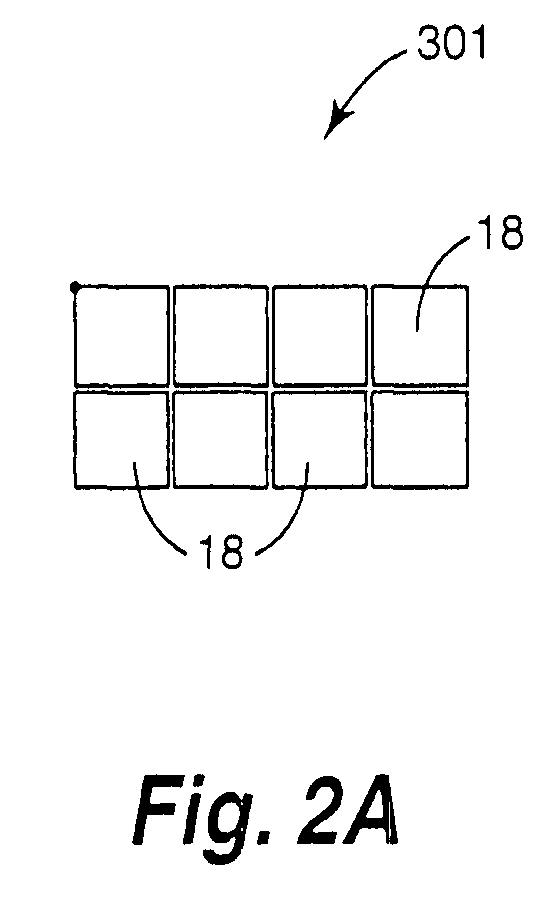
- image processing unit 24 defines a plurality of image sub-frames 30 for image frame 28. More specifically, image processing unit 24 defines a first sub-frame 301 and a second sub-frame 302 for image frame 28. As such, first sub-frame 301 and second sub-frame 302 each include a plurality of columns and a plurality of rows of individual pixels 18 of image data 16. Thus, first sub-frame 301 and second sub-frame 302 each constitute an image data array or pixel matrix of a subset of image data 16.
- second sub-frame 302 is offset from first sub-frame 301 by a vertical distance 50 and a horizontal distance 52. As such, second sub-frame 302 is spatially offset from first sub-frame 301 by a predetermined distance. In one illustrative embodiment, vertical distance 50 and horizontal distance 52 are each approximately one-half of one pixel.
- display device 26 alternates between displaying first sub-frame 301 in a first position and displaying second sub-frame 302 in a second position spatially offset from the first position. More specifically, display device 26 shifts display of second sub-frame 302 relative to display of first sub-frame 301 by vertical distance 50 and horizontal distance 52. As such, pixels of first sub-frame 301 overlap pixels of second sub-frame 302. In one embodiment, display device 26 completes one cycle of displaying first sub-frame 301 in the first position and displaying second sub-frame 302 in the second position for image frame 28. Thus, second sub-frame 302 is spatially and temporally displayed relative to first sub-frame 301.
- Figures 3A-3C illustrate one embodiment of completing one cycle of displaying a pixel 181 from first sub-frame 301 in the first position and displaying a pixel 182 from second sub-frame 302 in the second position. More specifically, Figure 3A illustrates display of pixel 181 from first sub-frame 301 in the first position, Figure 3B illustrates display of pixel 182 from second sub-frame 302 in the second position (with the first position being illustrated by dashed lines), and Figure 3C illustrates display of pixel 181 from first sub-frame 301 in the first position (with the second position being illustrated by dashed lines).
- Figures 4 and 5 illustrate enlarged image portions produced from the same image data without and with, respectively, image processing by image display system 10. More specifically, Figure 4 illustrates an enlarged image portion 60 produced without processing by image display system 10. As illustrated in Figure 4, enlarged image portion 60 appears pixelated with individual pixels being readily visible. In addition, enlarged image portion 60 is of a lower resolution.
- Figure 5 illustrates an enlarged image portion 62 produced with processing by image display system 10.
- enlarged image portion 62 does not appear as pixelated as enlarged image portion 60 of Figure 4.
- image quality of enlarged image portion 62 is enhanced with image display system 10. More specifically, resolution of enlarged image portion 62 is improved or increased compared to enlarged image portion 60.
- enlarged image portion 62 is produced by two-position processing including a first sub-frame and a second sub-frame, as described above.
- twice the amount of pixel data is used to create enlarged image portion 62 as compared to the amount of pixel data used to create enlarged image portion 60.
- the resolution of enlarged image portion 62 is increased relative to the resolution of enlarged image portion 60 by a factor of approximately 1.4 or the square root of two.
- image processing unit 24 defines a plurality of image sub-frames 30 for image frame 28. More specifically, image processing unit 24 defines a first sub-frame 301, a second sub-frame 302, a third sub-frame 303, and a fourth sub-frame 304 for image frame 28. As such, first sub-frame 301, second sub-frame 302, third sub-frame 303, and fourth sub-frame 304 each include a plurality of columns and a plurality of rows of individual pixels 18 of image data 16.
- second sub-frame 302 is offset from first sub-frame 301 by a vertical distance 50 and a horizontal distance 52
- third sub-frame 303 is offset from first sub-frame 301 by a horizontal distance 54
- fourth sub-frame 304 is offset from first sub-frame 301 by a vertical distance 56.
- second sub-frame 302, third sub-frame 303, and fourth sub-frame 304 are each spatially offset from each other and spatially offset from first sub-frame 301 by a predetermined distance.
- vertical distance 50, horizontal distance 52, horizontal distance 54, and vertical distance 56 are each approximately one-half of one pixel.
- display device 26 alternates between displaying first sub-frame 301 in a first position P 1 , displaying second sub-frame 302 in a second position P 2 spatially offset from the first position, displaying third sub-frame 303 in a third position P 3 spatially offset from the first position, and displaying fourth sub-frame 304 in a fourth position P 4 spatially offset from the first position. More specifically, display device 26 shifts display of second sub-frame 302, third sub-frame 303, and fourth sub-frame 304 relative to first sub-frame 301 by the respective predetermined distance. As such, pixels of first sub-frame 301, second sub-frame 302, third sub-frame 303, and fourth sub-frame 304 overlap each other.
- display device 26 completes one cycle of displaying first sub-frame 301 in the first position, displaying second sub-frame 302 in the second position, displaying third sub-frame 303 in the third position, and displaying fourth sub-frame 304 in the fourth position for image frame 28.
- second sub-frame 302, third sub-frame 303, and fourth sub-frame 304 are spatially and temporally displayed relative to each other and relative to first sub-frame 301.
- Figures 7A-7E illustrate one embodiment of completing one cycle of displaying a pixel 181 from first sub-frame 301 in the first position, displaying a pixel 182 from second sub-frame 302 in the second position, displaying a pixel 183 from third sub-frame 303 in the third position, and displaying a pixel 184 from fourth sub-frame 304 in the fourth position.
- Figure 7A illustrates display of pixel 181 from first sub-frame 301 in the first position
- Figure 7B illustrates display of pixel 182 from second sub-frame 302 in the second position (with the first position being illustrated by dashed lines)
- Figure 7C illustrates display of pixel 183 from third sub-frame 303 in the third position (with the first position and the second position being illustrated by dashed lines)
- Figure 7D illustrates display of pixel 184 from fourth sub-frame 304 in the fourth position (with the first position, the second position, and the third position being illustrated by dashed lines)
- Figure 7E illustrates display of pixel 181 from first sub-frame 301 in the first position (with the second position, the third position, and the fourth position being illustrated by dashed lines).
- Figures 8 and 9 illustrate enlarged image portions produced from the same image data without and with, respectively, image processing by image display system 10. More specifically, Figure 8 illustrates an enlarged image portion 64 produced without processing by image display system 10. As illustrated in Figure 8, areas of enlarged image portion 64 appear pixelated with individual pixels including, for example, pixels forming and/or outlining letters of enlarged image portion 64 being readily visible.
- Figure 9 illustrates an enlarged image portion 66 produced with processing by image display system 10.
- enlarged image portion 66 does not appear pixelated compared to enlarged image portion 64 of Figure 8.
- image quality of enlarged image portion 66 is enhanced with image display system 10. More specifically, resolution of enlarged image portion 66 is improved or increased compared to enlarged image portion 64.
- enlarged image portion 66 is produced by four-position processing including a first sub-frame, a second sub-frame, a third sub-frame, and a fourth sub-frame, as described above.
- four times the amount of pixel data is used to create enlarged image portion 66 as compared to the amount of pixel data used to create enlarged image portion 64.
- the resolution of enlarged image portion 64 is increased relative to the resolution of enlarged image portion 64 by a factor of two or the square root of four.
- Four-position processing therefore, allows image data 16 to be displayed at double the resolution of display device 26 since double the number of pixels in each axis (x and y) gives four times as many pixels.
- image display system 10 can produce displayed image 14 with a resolution greater than that of display device 26.
- image data 16 having a resolution of 800 pixels by 600 pixels
- display device 26 having a resolution of 800 pixels by 600 pixels
- four-position processing by image display system 10 with resolution adjustment of image data 16 produces displayed image 14 with a resolution of 1600 pixels by 1200 pixels. Accordingly, with lower resolution image data and a lower resolution display device, image display system 10 can produce a higher resolution displayed image.
- image display system 10 can produce a higher resolution displayed image.
- image display system 10 can reduce the "screen-door" effect caused, for example, by gaps between adjacent micro-mirror devices of a light modulator.
- image display system 10 can produce displayed image 14 with improved resolution over the entire image.
- image display system 10 can produce displayed image 14 with an increased resolution greater than that of display device 26.
- higher resolution data can be supplied to image display system 10 as original image data or synthesized by image display system 10 from the original image data.
- lower resolution data can be supplied to image display system 10 and used to produce displayed image 14 with a resolution greater than that of display device 26.
- Use of lower resolution data allows for sending of images at a lower data rate while still allowing for higher resolution display of the data.
- use of a lower data rate may enable lower speed data interfaces and result in potentially less EMI radiation.
Abstract

Description
- The present invention relates generally to imaging systems, and more particularly to a system and method of displaying an image.
- A conventional system or device for displaying an image, such as a display, projector, or other imaging system, produces a displayed image by addressing an array of individual picture elements or pixels arranged in horizontal rows and vertical columns. A resolution of the displayed image is defined as the number of horizontal rows and vertical columns of individual pixels forming the displayed image. The resolution of the displayed image is affected by a resolution of the display device itself as well as a resolution of the image data processed by the display device and used to produce the displayed image.
- Typically, to increase a resolution of the displayed image, the resolution of the display device as well as the resolution of the image data used to produce the displayed image must be increased. Increasing a resolution of the display device, however, increases a cost and complexity of the display device. In addition, higher resolution image data may not be available and/or may be difficult to generate.
- Accordingly, it is desired to increase a resolution of a displayed image without having to increase a resolution of a display device displaying the displayed image and/or with or without having to increase a resolution of image data used to produce the displayed image.
- One aspect of the present invention provides a method of displaying an image. The method includes receiving image data for the image, buffering the image data for the image, including creating a frame of the image, defining a first sub-frame and at least a second sub-frame for the frame of the image from the image data, the second sub-frame being spatially offset from the first sub-frame, and alternating between displaying the first sub-frame in a first position and displaying the second sub-frame in a second position spatially offset from the first position.
- Figure 1 is a block diagram illustrating one embodiment of an image display system.
- Figures 2A-2C are schematic illustrations of one embodiment of processing and displaying a frame of an image according to the present invention.
- Figures 3A-3C are schematic illustrations of one embodiment of displaying a pixel with an image display system according to the present invention.
- Figure 4 is a simulation of one embodiment of an enlarged image portion produced without processing by an image display system according to the present invention.
- Figure 5 is a simulation of one embodiment of an enlarged image portion produced with processing by an image display system according to the present invention.
- Figures 6A-6E are schematic illustrations of another embodiment of processing and displaying a frame of an image according to the present invention.
- Figures 7A-7E are schematic illustrations of one embodiment of displaying a pixel with an image display system according to the present invention.
- Figure 8 is a simulation of another embodiment of an enlarged image portion produced without processing by an image display system according to the present invention.
- Figure 9 is a simulation of another embodiment of an enlarged image portion produced with processing by an image display system according to the present invention.
- In the following detailed description of the preferred embodiments, reference is made to the accompanying drawings which form a part hereof, and in which is shown by way of illustration specific embodiments in which the invention may be practiced. It is to be understood that other embodiments may be utilized and structural or logical changes may be made without departing from the scope of the present invention. The following detailed description, therefore, is not to be taken in a limiting sense, and the scope of the present invention is defined by the appended claims.
- Figure 1 illustrates one embodiment of an
image display system 10.Image display system 10 facilitates processing of animage 12 to create a displayedimage 14.Image 12 is defined to include any pictorial, graphical, and/or textural characters, symbols, illustrations, and/or other representation of information.Image 12 is represented, for example, byimage data 16.Image data 16 includes individual picture elements or pixels ofimage 12. While one image is illustrated and described as being processed byimage display system 10, it is understood that a plurality or series of images may be processed and displayed byimage display system 10. - In one embodiment,
image display system 10 includes a framerate conversion unit 20 and animage frame buffer 22, animage processing unit 24, and adisplay device 26. As described below, framerate conversion unit 20 andimage frame buffer 22 receive andbuffer image data 16 forimage 12 to create animage frame 28 forimage 12. In addition,image processing unit 24processes image frame 28 to define one ormore image sub-frames 30 forimage frame 28, anddisplay device 26 temporally and spatially displaysimage sub-frames 30 to produce displayedimage 14. -
Image display system 10, including framerate conversion unit 20 and/orimage processing unit 24, includes hardware, software, firmware, or a combination of these. In one embodiment, one or more components ofimage display system 10, including framerate conversion unit 20 and/orimage processing unit 24, are included in a computer, computer server, or other microprocessor-based system capable of performing a sequence of logic operations. In addition, processing can be distributed throughout the system with individual portions being implemented in separate system components. -
Image data 16 may includedigital image data 161 oranalog image data 162. To processanalog image data 162,image display system 10 includes an analog-to-digital (A/D)converter 32. As such, A/D converter 32 convertsanalog image data 162 to digital form for subsequent processing. Thus,image display system 10 may receive and processdigital image data 161 and/oranalog image data 162 forimage 12. - Frame
rate conversion unit 20 receivesimage data 16 forimage 12 and buffers or storesimage data 16 inimage frame buffer 22. More specifically, framerate conversion unit 20 receivesimage data 16 representing individual lines or fields ofimage 12 andbuffers image data 16 inimage frame buffer 22 to createimage frame 28 forimage 12.Image frame buffer 22buffers image data 16 by receiving and storing all of the image data forimage frame 28 and framerate conversion unit 20 createsimage frame 28 by subsequently retrieving or extracting all of the image data forimage frame 28 fromimage frame buffer 22. As such,image frame 28 is defined to include a plurality of individual lines or fields ofimage data 16 representing an entirety ofimage 12. Thus,image frame 28 includes a plurality of columns and a plurality of rows of individualpixels representing image 12. - Frame
rate conversion unit 20 andimage frame buffer 22 can receive and processimage data 16 as progressive image data and/or interlaced image data. With progressive image data, framerate conversion unit 20 andimage frame buffer 22 receive and store sequential fields ofimage data 16 forimage 12. Thus, framerate conversion unit 20 createsimage frame 28 by retrieving the sequential fields ofimage data 16 forimage 12. With interlaced image data, framerate conversion unit 20 andimage frame buffer 22 receive and store odd fields and even fields ofimage data 16 forimage 12. For example, all of the odd fields ofimage data 16 are received and stored and all of the even fields ofimage data 16 are received and stored. As such, framerate conversion unit 20 de-interlacesimage data 16 and createsimage frame 28 by retrieving the odd and even fields ofimage data 16 forimage 12. -
Image frame buffer 22 includes memory for storingimage data 16 for one ormore image frames 28 ofrespective images 12. Thus,image frame buffer 22 constitutes a database of one ormore image frames 28. Examples ofimage frame buffer 22 include non-volatile memory (e.g., a hard disk drive or other persistent storage device) and may include volatile memory (e.g., random access memory (RAM)). - By receiving
image data 16 at framerate conversion unit 20 andbuffering image data 16 withimage frame buffer 22, input timing ofimage data 16 can be decoupled from a timing requirement ofdisplay device 26. More specifically, sinceimage data 16 forimage frame 28 is received and stored byimage frame buffer 22,image data 16 can be received as input at any rate. As such, the frame rate ofimage frame 28 can be converted to the timing requirement ofdisplay device 26. Thus,image data 16 forimage frame 28 can be extracted fromimage frame buffer 22 at a frame rate ofdisplay device 26. - In one embodiment,
image processing unit 24 includes aresolution adjustment unit 34 and asub-frame generation unit 36. As described below,resolution adjustment unit 34 receivesimage data 16 forimage frame 28 and adjusts a resolution ofimage data 16 for display ondisplay device 26, andsub-frame generation unit 36 generates a plurality ofimage sub-frames 30 forimage frame 28. More specifically,image processing unit 24 receivesimage data 16 forimage frame 28 at an original resolution and processesimage data 16 to match the resolution ofdisplay device 26. For example,image processing unit 24 increases, decreases, and/or leaves unaltered the resolution ofimage data 16 so as to match the resolution ofdisplay device 26. Thus, by matching the resolution ofimage data 16 to the resolution ofdisplay device 26,display device 26 can displayimage data 16. Accordingly, withimage processing unit 24,image display system 10 can receive and displayimage data 16 of varying resolutions. - In one embodiment,
image processing unit 24 increases a resolution ofimage data 16. For example,image data 16 may be of a resolution less than that ofdisplay device 26. More specifically,image data 16 may include lower resolution data, such as 400 pixels by 300 pixels, anddisplay device 26 may support higher resolution data, such as 800 pixels by 600 pixels. As such,image processing unit 24processes image data 16 to increase the resolution ofimage data 16 to the resolution ofdisplay device 26.Image processing unit 24 may increase the resolution ofimage data 16 by, for example, pixel replication, interpolation, and/or any other resolution synthesis or generation technique. - In one embodiment,
image processing unit 24 decreases a resolution ofimage data 16. For example,image data 16 may be of a resolution greater than that ofdisplay device 26. More specifically,image data 16 may include higher resolution data, such as 1600 pixels by 1200 pixels, anddisplay device 26 may support lower resolution data, such as 800 pixels by 600 pixels. As such,image processing unit 24processes image data 16 to decrease the resolution ofimage data 16 to the resolution ofdisplay device 26.image processing unit 24 may decrease the resolution ofimage data 16 by, for example, sub-sampling, interpolation, and/or any other resolution reduction technique. -
Sub-frame generation unit 36 receives and processesimage data 16 forimage frame 28 to define a plurality ofimage sub-frames 30 forimage frame 28. Ifresolution adjustment unit 34 has adjusted the resolution ofimage data 16,sub-frame generation unit 36 receivesimage data 16 at the adjusted resolution. The adjusted resolution ofimage data 16 may be increased, decreased, or the same as the original resolution ofimage data 16 forimage frame 28.Sub-frame generation unit 36 generatesimage sub-frames 30 with a resolution which matches the resolution ofdisplay device 26.Image sub-frames 30 are each of an area equal to imageframe 28 and each include a plurality of columns and a plurality of rows of individual pixels representing a subset ofimage data 16 ofimage 12 and have a resolution which matches the resolution ofdisplay device 26. - Each
image sub-frame 30 includes a matrix or array of pixels forimage frame 28.Image sub-frames 30 are spatially offset from each other such that eachimage sub-frame 30 includes different pixels and/or portions of pixels. As such,image sub-frames 30 are offset from each other by a vertical distance and/or a horizontal distance, as described below. -
Display device 26 receivesimage sub-frames 30 fromimage processing unit 24 and sequentiallydisplays image sub-frames 30 to create displayedimage 14. More specifically, asimage sub-frames 30 are spatially offset from each other,display device 26displays image sub-frames 30 in different positions according to the spatial offset ofimage sub-frames 30, as described below. As such,display device 26 alternates between displayingimage sub-frames 30 forimage frame 28 to create displayedimage 14. Accordingly,display device 26 displays anentire sub-frame 30 forimage frame 28 at one time. - In one embodiment,
display device 26 completes one cycle of displayingimage sub-frames 30 forimage frame 28. Thus,display device 26displays image sub-frames 30 so as to be spatially and temporally offset from each other. In one embodiment,display device 26 optically steersimage sub-frames 30 to create displayedimage 14. As such, individual pixels ofdisplay device 26 are addressed to multiple locations. - In one embodiment,
display device 26 includes animage shifter 38.Image shifter 38 spatially alters or offsets the position ofimage sub-frames 30 as displayed bydisplay device 26. More specifically,image shifter 38 varies the position of display ofimage sub-frames 30, as described below, to produce displayedimage 14. - In one embodiment,
display device 26 includes a light modulator for modulation of incident light. The light modulator includes, for example, a plurality of micro-mirror devices arranged to form an array of micro-mirror devices. As such, each micro-mirror device constitutes one cell or pixel ofdisplay device 26.Display device 26 may form part of a display, projector, or other imaging system. - In one embodiment,
image display system 10 includes atiming generator 40. Timinggenerator 40 communicates, for example, with framerate conversion unit 20,image processing unit 24, includingresolution adjustment unit 34 andsub-frame generation unit 36, anddisplay device 26, includingimage shifter 38. As such,timing generator 40 synchronizes buffering and conversion ofimage data 16 to createimage frame 28, processing ofimage frame 28 to adjust the resolution ofimage data 16 to the resolution ofdisplay device 26 and generateimage sub-frames 30, and display and positioning ofimage sub-frames 30 to produce displayedimage 14. Accordingly,timing generator 40 controls timing ofimage display system 10 such that entire sub-frames ofimage 12 are temporally and spatially displayed bydisplay device 26 as displayedimage 14. - In one embodiment, as illustrated in Figures 2A and 2B,
image processing unit 24 defines a plurality ofimage sub-frames 30 forimage frame 28. More specifically,image processing unit 24 defines afirst sub-frame 301 and asecond sub-frame 302 forimage frame 28. As such,first sub-frame 301 andsecond sub-frame 302 each include a plurality of columns and a plurality of rows ofindividual pixels 18 ofimage data 16. Thus,first sub-frame 301 andsecond sub-frame 302 each constitute an image data array or pixel matrix of a subset ofimage data 16. - In one embodiment, as illustrated in Figure 2B,
second sub-frame 302 is offset fromfirst sub-frame 301 by avertical distance 50 and ahorizontal distance 52. As such,second sub-frame 302 is spatially offset fromfirst sub-frame 301 by a predetermined distance. In one illustrative embodiment,vertical distance 50 andhorizontal distance 52 are each approximately one-half of one pixel. - As illustrated in Figure 2C,
display device 26 alternates between displayingfirst sub-frame 301 in a first position and displayingsecond sub-frame 302 in a second position spatially offset from the first position. More specifically,display device 26 shifts display ofsecond sub-frame 302 relative to display offirst sub-frame 301 byvertical distance 50 andhorizontal distance 52. As such, pixels offirst sub-frame 301 overlap pixels ofsecond sub-frame 302. In one embodiment,display device 26 completes one cycle of displayingfirst sub-frame 301 in the first position and displayingsecond sub-frame 302 in the second position forimage frame 28. Thus,second sub-frame 302 is spatially and temporally displayed relative tofirst sub-frame 301. - Figures 3A-3C illustrate one embodiment of completing one cycle of displaying a
pixel 181 fromfirst sub-frame 301 in the first position and displaying apixel 182 fromsecond sub-frame 302 in the second position. More specifically, Figure 3A illustrates display ofpixel 181 fromfirst sub-frame 301 in the first position, Figure 3B illustrates display ofpixel 182 fromsecond sub-frame 302 in the second position (with the first position being illustrated by dashed lines), and Figure 3C illustrates display ofpixel 181 fromfirst sub-frame 301 in the first position (with the second position being illustrated by dashed lines). - Figures 4 and 5 illustrate enlarged image portions produced from the same image data without and with, respectively, image processing by
image display system 10. More specifically, Figure 4 illustrates anenlarged image portion 60 produced without processing byimage display system 10. As illustrated in Figure 4,enlarged image portion 60 appears pixelated with individual pixels being readily visible. In addition,enlarged image portion 60 is of a lower resolution. - Figure 5, however, illustrates an
enlarged image portion 62 produced with processing byimage display system 10. As illustrated in Figure 5,enlarged image portion 62 does not appear as pixelated asenlarged image portion 60 of Figure 4. Thus, image quality ofenlarged image portion 62 is enhanced withimage display system 10. More specifically, resolution ofenlarged image portion 62 is improved or increased compared toenlarged image portion 60. - In one illustrative embodiment,
enlarged image portion 62 is produced by two-position processing including a first sub-frame and a second sub-frame, as described above. Thus, twice the amount of pixel data is used to createenlarged image portion 62 as compared to the amount of pixel data used to createenlarged image portion 60. Accordingly, with two-position processing, the resolution ofenlarged image portion 62 is increased relative to the resolution ofenlarged image portion 60 by a factor of approximately 1.4 or the square root of two. - In another embodiment, as illustrated in Figures 6A-6D,
image processing unit 24 defines a plurality ofimage sub-frames 30 forimage frame 28. More specifically,image processing unit 24 defines afirst sub-frame 301, asecond sub-frame 302, athird sub-frame 303, and afourth sub-frame 304 forimage frame 28. As such,first sub-frame 301,second sub-frame 302,third sub-frame 303, andfourth sub-frame 304 each include a plurality of columns and a plurality of rows ofindividual pixels 18 ofimage data 16. - In one embodiment, as illustrated in Figure 6B-6D,
second sub-frame 302 is offset fromfirst sub-frame 301 by avertical distance 50 and ahorizontal distance 52,third sub-frame 303 is offset fromfirst sub-frame 301 by ahorizontal distance 54, andfourth sub-frame 304 is offset fromfirst sub-frame 301 by avertical distance 56. As such,second sub-frame 302,third sub-frame 303, andfourth sub-frame 304 are each spatially offset from each other and spatially offset fromfirst sub-frame 301 by a predetermined distance. In one illustrative embodiment,vertical distance 50,horizontal distance 52,horizontal distance 54, andvertical distance 56 are each approximately one-half of one pixel. - As illustrated schematically in Figure 6E,
display device 26 alternates between displayingfirst sub-frame 301 in a first position P1, displayingsecond sub-frame 302 in a second position P2 spatially offset from the first position, displayingthird sub-frame 303 in a third position P3 spatially offset from the first position, and displayingfourth sub-frame 304 in a fourth position P4 spatially offset from the first position. More specifically,display device 26 shifts display ofsecond sub-frame 302,third sub-frame 303, andfourth sub-frame 304 relative tofirst sub-frame 301 by the respective predetermined distance. As such, pixels offirst sub-frame 301,second sub-frame 302,third sub-frame 303, andfourth sub-frame 304 overlap each other. - In one embodiment,
display device 26 completes one cycle of displayingfirst sub-frame 301 in the first position, displayingsecond sub-frame 302 in the second position, displayingthird sub-frame 303 in the third position, and displayingfourth sub-frame 304 in the fourth position forimage frame 28. Thus,second sub-frame 302,third sub-frame 303, andfourth sub-frame 304 are spatially and temporally displayed relative to each other and relative tofirst sub-frame 301. - Figures 7A-7E illustrate one embodiment of completing one cycle of displaying a
pixel 181 fromfirst sub-frame 301 in the first position, displaying apixel 182 fromsecond sub-frame 302 in the second position, displaying apixel 183 fromthird sub-frame 303 in the third position, and displaying apixel 184 fromfourth sub-frame 304 in the fourth position. More specifically, Figure 7A illustrates display ofpixel 181 fromfirst sub-frame 301 in the first position, Figure 7B illustrates display ofpixel 182 fromsecond sub-frame 302 in the second position (with the first position being illustrated by dashed lines), Figure 7C illustrates display ofpixel 183 fromthird sub-frame 303 in the third position (with the first position and the second position being illustrated by dashed lines), Figure 7D illustrates display ofpixel 184 fromfourth sub-frame 304 in the fourth position (with the first position, the second position, and the third position being illustrated by dashed lines), and Figure 7E illustrates display ofpixel 181 fromfirst sub-frame 301 in the first position (with the second position, the third position, and the fourth position being illustrated by dashed lines). - Figures 8 and 9 illustrate enlarged image portions produced from the same image data without and with, respectively, image processing by
image display system 10. More specifically, Figure 8 illustrates anenlarged image portion 64 produced without processing byimage display system 10. As illustrated in Figure 8, areas ofenlarged image portion 64 appear pixelated with individual pixels including, for example, pixels forming and/or outlining letters ofenlarged image portion 64 being readily visible. - Figure 9, however, illustrates an
enlarged image portion 66 produced with processing byimage display system 10. As illustrated in Figure 9,enlarged image portion 66 does not appear pixelated compared toenlarged image portion 64 of Figure 8. Thus, image quality ofenlarged image portion 66 is enhanced withimage display system 10. More specifically, resolution ofenlarged image portion 66 is improved or increased compared toenlarged image portion 64. - in one illustrative embodiment,
enlarged image portion 66 is produced by four-position processing including a first sub-frame, a second sub-frame, a third sub-frame, and a fourth sub-frame, as described above. Thus, four times the amount of pixel data is used to createenlarged image portion 66 as compared to the amount of pixel data used to createenlarged image portion 64. Accordingly, with four-position processing, the resolution ofenlarged image portion 64 is increased relative to the resolution ofenlarged image portion 64 by a factor of two or the square root of four. Four-position processing, therefore, allowsimage data 16 to be displayed at double the resolution ofdisplay device 26 since double the number of pixels in each axis (x and y) gives four times as many pixels. - By defining a plurality of
image sub-frames 30 forimage frame 28 and spatially and temporally displayingimage sub-frames 30 relative to each other,image display system 10 can produce displayedimage 14 with a resolution greater than that ofdisplay device 26. In one illustrative embodiment, for example, withimage data 16 having a resolution of 800 pixels by 600 pixels anddisplay device 26 having a resolution of 800 pixels by 600 pixels, four-position processing byimage display system 10 with resolution adjustment ofimage data 16 produces displayedimage 14 with a resolution of 1600 pixels by 1200 pixels. Accordingly, with lower resolution image data and a lower resolution display device,image display system 10 can produce a higher resolution displayed image. In another illustrative embodiment, for example, withimage data 16 having a resolution of 1600 pixels by 1200 pixels anddisplay device 26 having a resolution of 800 pixels by 600 pixels, four-position processing byimage display system 10 without resolution adjustment ofimage data 16 produces displayedimage 14 with a resolution of 1600 pixels by 1200 pixels. Accordingly, with higher resolution image data and a lower resolution display device,image display system 10 can produce a higher resolution displayed image. In addition, by overlapping pixels ofimage sub-frames 30 while spatially and temporally displayingimage sub-frames 30 relative to each other,image display system 10 can reduce the "screen-door" effect caused, for example, by gaps between adjacent micro-mirror devices of a light modulator. - By buffering
image data 16 to createimage frame 28 and decouple a timing ofimage data 16 from a frame rate ofdisplay device 26 and displaying anentire sub-frame 30 forimage frame 28 at once,image display system 10 can produce displayedimage 14 with improved resolution over the entire image. In addition, with image data of a resolution equal to or greater than a resolution ofdisplay device 26,image display system 10 can produce displayedimage 14 with an increased resolution greater than that ofdisplay device 26. To produce displayedimage 14 with a resolution greater than that ofdisplay device 26, higher resolution data can be supplied to imagedisplay system 10 as original image data or synthesized byimage display system 10 from the original image data. Alternatively, lower resolution data can be supplied to imagedisplay system 10 and used to produce displayedimage 14 with a resolution greater than that ofdisplay device 26. Use of lower resolution data allows for sending of images at a lower data rate while still allowing for higher resolution display of the data. Thus, use of a lower data rate may enable lower speed data interfaces and result in potentially less EMI radiation. - Although specific embodiments have been illustrated and described herein for purposes of description of the preferred embodiment, it will be appreciated by those of ordinary skill in the art that a wide variety of alternate and/or equivalent implementations calculated to achieve the same purposes may be substituted for the specific embodiments shown and described without departing from the scope of the present invention. Those with skill in the chemical, mechanical, electro-mechanical, electrical, and computer arts will readily appreciate that the present invention may be implemented in a very wide variety of embodiments. This application is intended to cover any adaptations or variations of the preferred embodiments discussed herein. Therefore, it is manifestly intended that this invention be limited only by the claims and the equivalents thereof.
Claims (20)
- A method of displaying an image, the method comprising:receiving image data (16) for the image;buffering the image data for the image, including creating a frame (28)of the image;defining a first sub-frame (301 ) and at least a second sub-frame (302) for the frame of the image from the image data, the second sub-frame being spatially offset from the first sub-frame; andalternating between displaying the first sub-frame in a first position and displaying the second sub-frame in a second position spatially offset from the first position.
- The method of claim 1, wherein the image data includes individual pixels (18) of the image, wherein the frame of the image includes a plurality of columns and a plurality of rows of the individual pixels of the image, and wherein defining the first sub-frame and the second sub-frame includes defining a first pixel matrix and at least a second pixel matrix for the frame of the image from the image data.
- The method of claim 2, wherein alternating between displaying the first sub-frame and displaying the second sub-frame includes overlapping pixels of the first pixel matrix with pixels of the second pixel matrix.
- The method of claim 1, wherein defining the first sub-frame and the second sub-frame includes adjusting a resolution of the image data.
- The method of claim 1, wherein the second sub-frame is offset at least one of a vertical distance (50) and a horizontal distance (52) from the first sub-frame, and wherein alternating between displaying the first sub-frame and displaying the second sub-frame includes shifting display of the second sub-frame the at least one of the vertical distance and the horizontal distance from the first sub-frame.
- The method of claim 1, wherein defining the second sub-frame further includes defining a third sub-frame (303) and a fourth sub-frame (304) for the frame of the image from the image data, the fourth sub-frame being spatially offset from the third sub-frame and the third sub-frame and the fourth sub-frame both being spatially offset from the first sub-frame and the second sub-frame, and
wherein alternating between displaying the first sub-frame and displaying the second sub-frame further includes alternating between displaying the first sub-frame in the first position, displaying the second sub-frame in the second position, displaying the third sub-frame in a third position spatially offset from the first position and the second position, and displaying the fourth sub-frame in a fourth position spatially offset from the first position, the second position, and the third position. - A method of displaying an image with a display device (26), the method comprising:receiving image data (16) for the image, the image data including individual pixels (18) of the image;buffering the image data and creating a frame (28) of the image, the frame of the image including a plurality of columns and a plurality of rows of the pixels of the image;separating the frame of the image into a first pixel matrix (301) and at least one second pixel matrix (302) spatially offset from the first pixel matrix; anddisplaying the first pixel matrix and the second pixel matrix with the display device, including spatially and temporally displaying the second pixel matrix relative to the first pixel matrix.
- The method of claim 7, wherein spatially and temporally displaying the second pixel matrix relative to the first pixel matrix includes overlapping pixels of the first pixel matrix with pixels of the second pixel matrix.
- The method of claim 7, further comprising:matching a resolution of the image data to a resolution of the display device.
- The method of claim 7, wherein separating the frame of the image into the first pixel matrix and the second pixel matrix further includes separating the frame of the image into a third pixel matrix (303) and a fourth pixel matrix (304) spatially offset from the third pixel matrix, the third pixel matrix and the fourth pixel matrix both being spatially offset from the first pixel matrix and the second pixel matrix, and wherein displaying the first pixel matrix and the second pixel matrix further includes displaying the first pixel matrix, the second pixel matrix, the third pixel matrix, and the fourth pixel matrix with the display device, including spatially and temporally displaying the first pixel matrix, the second pixel matrix, the third pixel matrix, and the fourth pixel matrix relative to each other.
- A system for displaying an image, the system comprising:a buffer (22) adapted to receive image data (16) for the image and buffer the image data to create a frame (28) of the image;an image processing unit (24) adapted to define a first sub-frame (301) and at least a second sub-frame (302) for the frame of the image from the image data, the second sub-frame being spatially offset from the first sub-frame; anda display device (26) adapted to alternately display the first sub-frame in a first position and the second sub-frame in a second position spatially offset from the first position.
- The system of claim 11, further comprising:wherein the frame rate conversion unit is adapted to receive the image data for the image at a first rate and retrieve the image data from the buffer at a second rate.a frame rate conversion unit (20) adapted to receive the image data for the image, store the image data in the buffer, and retrieve the image data from the buffer to create the image frame for the image,
- The system of claim 11, wherein the image processing unit is adapted to match a resolution of the image data to a resolution of the display device.
- The system of claim 11, wherein the image data includes individual pixels (18) of the image, wherein the frame of the image includes a plurality of columns and a plurality of rows of the individual pixels of the image, wherein the image processing unit is adapted to define a first pixel matrix (301) and at least a second pixel matrix (302) of the image from the image data, and wherein the display device is adapted to overlap pixels of the first pixel matrix with pixels of the second pixel matrix.
- The system of claim 11, wherein the second sub-frame is spatially offset at least one of a vertical distance (50) and a horizontal distance (52) from the first sub-frame, and wherein the display device is adapted to shift display of the second sub-frame from display of the first sub-frame by the at least one of the vertical distance and the horizontal distance.
- A system for displaying an image, the system comprising:means for receiving image data (16) for the image at a first rate and creating a frame (28) of the image at a second rate;means for defining a first sub-frame (301) and at least a second sub-frame (302) for the frame of the image from the image data, the second sub-frame being spatially offset from the first sub-frame; andmeans for sequentially displaying the first sub-frame in a first position and the second sub-frame in a second position spatially offset from the first position.
- The system of claim 16, wherein means for sequentially displaying the first sub-frame and the second sub-frame includes means for displaying the first sub-frame and the second sub-frame with a predetermined resolution, and further comprising:means for adjusting a resolution of the image data for the image to the predetermined resolution.
- The system of claim 17, wherein means for sequentially displaying the first sub-frame and the second sub-frame includes means for shifting between the first position and the second position.
- The system of claim 18, further comprising:means for synchronizing timing of creating the frame of the image, sequentially displaying the first sub-frame and the second sub-frame for the frame of the image, and shifting between the first position and the second position.
- The system of claim 16, wherein the image data includes individual pixels (18) of the image, and wherein means for sequentially displaying the first sub-frame and the second sub-frame includes means for overlapping pixels of the first sub-frame with pixels of the second sub-frame.
Applications Claiming Priority (2)
| Application Number | Priority Date | Filing Date | Title |
|---|---|---|---|
| US213555 | 1980-12-05 | ||
| US10/213,555 US7030894B2 (en) | 2002-08-07 | 2002-08-07 | Image display system and method |
Publications (2)
| Publication Number | Publication Date |
|---|---|
| EP1388838A2 true EP1388838A2 (en) | 2004-02-11 |
| EP1388838A3 EP1388838A3 (en) | 2006-09-06 |
Family
ID=30443706
Family Applications (1)
| Application Number | Title | Priority Date | Filing Date |
|---|---|---|---|
| EP03254579A Withdrawn EP1388838A3 (en) | 2002-08-07 | 2003-07-22 | Image display system and method |
Country Status (6)
| Country | Link |
|---|---|
| US (2) | US7030894B2 (en) |
| EP (1) | EP1388838A3 (en) |
| JP (1) | JP2004070358A (en) |
| KR (1) | KR100567511B1 (en) |
| CN (1) | CN100348027C (en) |
| TW (1) | TWI225370B (en) |
Cited By (13)
| Publication number | Priority date | Publication date | Assignee | Title |
|---|---|---|---|---|
| WO2005013256A2 (en) * | 2003-07-31 | 2005-02-10 | Hewlett-Packard Development Company, L.P. | Generating and alternately displaying spatially offset sub frames |
| WO2005098805A2 (en) * | 2004-04-08 | 2005-10-20 | Hewlett-Packard Development Company, L.P. | Generating and displaying spatially offset sub-frames |
| WO2005101368A1 (en) * | 2004-04-08 | 2005-10-27 | Hewlett-Packard Development Company, L.P. | Generating and displaying spatially offset sub-frames to provide higher resolution image |
| WO2005101356A2 (en) * | 2004-04-08 | 2005-10-27 | Hewlett-Packard Development Company, L.P. | Generating and displaying spatially offset sub-frames |
| WO2005124684A2 (en) * | 2004-06-15 | 2005-12-29 | Hewlett-Packard Development Company, L.P. | Generating and displaying spatially offset sub-frames |
| WO2005124733A1 (en) * | 2004-06-09 | 2005-12-29 | Hewlett-Packard Development Company, L.P. | Generating and displaying spatially offset sub-frames |
| WO2006002007A1 (en) * | 2004-06-15 | 2006-01-05 | Hewlett-Packard Development Company, L.P. | Generating and displaying spatially offset sub-frames |
| WO2006019953A1 (en) * | 2004-07-29 | 2006-02-23 | Hewlett-Packard Development Company, L.P. | Address generation in a light modulator |
| WO2006044042A1 (en) * | 2004-10-20 | 2006-04-27 | Hewlett-Packard Development Company, L.P. | Generating and displaying spatially offset sub-frames |
| WO2006055924A1 (en) * | 2004-11-19 | 2006-05-26 | Hewlett-Packard Development Company, L.P. | Generating and displaying spatially offset sub-frames |
| EP1388839A3 (en) * | 2002-08-07 | 2006-09-06 | Hewlett-Packard Development Company, L.P. | Image display system and method |
| EP1388840A3 (en) * | 2002-08-07 | 2006-09-27 | Hewlett-Packard Development Company, L.P. | Image display system and method |
| WO2007017297A1 (en) | 2005-08-10 | 2007-02-15 | Tte Technology, Inc. | A system and method for generating images |
Families Citing this family (37)
| Publication number | Priority date | Publication date | Assignee | Title |
|---|---|---|---|---|
| US7343052B2 (en) * | 2002-04-09 | 2008-03-11 | Sonic Solutions | End-user-navigable set of zoomed-in images derived from a high-resolution master image |
| US20050093894A1 (en) * | 2003-10-30 | 2005-05-05 | Tretter Daniel R. | Generating an displaying spatially offset sub-frames on different types of grids |
| DE502005004008D1 (en) | 2004-05-10 | 2008-06-19 | Envisiontec Gmbh | METHOD FOR PRODUCING A THREE-DIMENSIONAL OBJECT WITH RESOLUTION OF IMPROVEMENT BY PIXEL SHIFT |
| DE102004022961B4 (en) * | 2004-05-10 | 2008-11-20 | Envisiontec Gmbh | Method for producing a three-dimensional object with resolution improvement by means of pixel shift |
| US7450784B2 (en) * | 2004-08-31 | 2008-11-11 | Olympus Corporation | Image resolution converting device |
| US7255448B2 (en) * | 2004-10-20 | 2007-08-14 | Hewlett-Packard Development Company, L.P. | Pixelated color management display |
| US7465054B2 (en) * | 2004-10-29 | 2008-12-16 | Hewlett-Packard Development Company, L.P. | Focusing arrangement |
| US7279812B2 (en) * | 2005-01-18 | 2007-10-09 | Hewlett-Packard Development Company, L.P. | Light direction assembly shorted turn |
| JP4777675B2 (en) * | 2005-03-17 | 2011-09-21 | 株式会社リコー | Image processing apparatus, image display apparatus, image processing method, program for causing computer to execute the method, and recording medium |
| US20060279702A1 (en) * | 2005-06-09 | 2006-12-14 | Kettle Wiatt E | Projection assembly |
| KR100718233B1 (en) * | 2005-08-18 | 2007-05-15 | 삼성전자주식회사 | Projection apparatus and control method thereof |
| JP4325599B2 (en) * | 2005-08-25 | 2009-09-02 | ソニー株式会社 | Imaging apparatus and display control method |
| US20070076171A1 (en) * | 2005-09-20 | 2007-04-05 | Fasen Donald J | Wobulator position sensing system and method |
| US7770523B2 (en) * | 2005-10-07 | 2010-08-10 | University Of South Florida | Interactive amusement park attraction vehicle |
| JP2007192919A (en) * | 2006-01-17 | 2007-08-02 | Olympus Corp | Image display device |
| US20070173971A1 (en) * | 2006-01-26 | 2007-07-26 | Prairiestone Pharmacy, Llc | System and method of providing medication compliance packaging |
| US7460133B2 (en) * | 2006-04-04 | 2008-12-02 | Sharp Laboratories Of America, Inc. | Optimal hiding for defective subpixels |
| DE102006019963B4 (en) * | 2006-04-28 | 2023-12-07 | Envisiontec Gmbh | Device and method for producing a three-dimensional object by layer-by-layer solidifying a material that can be solidified under the influence of electromagnetic radiation using mask exposure |
| DE102006019964C5 (en) * | 2006-04-28 | 2021-08-26 | Envisiontec Gmbh | Device and method for producing a three-dimensional object by means of mask exposure |
| US20080007501A1 (en) * | 2006-07-10 | 2008-01-10 | Larson Arnold W | Display system |
| US8300067B2 (en) * | 2006-11-16 | 2012-10-30 | Freedom Scientific, Inc. | Distance camera having a memory module |
| KR101325069B1 (en) | 2006-12-15 | 2013-11-05 | 엘지디스플레이 주식회사 | Image display device and image display method thereof |
| US20080143969A1 (en) * | 2006-12-15 | 2008-06-19 | Richard Aufranc | Dynamic superposition system and method for multi-projection display |
| JP4450014B2 (en) * | 2007-05-30 | 2010-04-14 | セイコーエプソン株式会社 | Projector, image display device, and image processing device |
| EP2052693B2 (en) | 2007-10-26 | 2021-02-17 | Envisiontec GmbH | Process and freeform fabrication system for producing a three-dimensional object |
| US8150214B2 (en) * | 2007-11-27 | 2012-04-03 | Microsoft Corporation | Inferred discovery and construction of multi-resolution images |
| JP5211992B2 (en) * | 2008-09-30 | 2013-06-12 | セイコーエプソン株式会社 | Image processing apparatus, image display apparatus, and image processing method |
| JP5320940B2 (en) * | 2008-09-30 | 2013-10-23 | セイコーエプソン株式会社 | Image processing apparatus and image display apparatus |
| CN102301729B (en) | 2009-01-28 | 2014-12-17 | 日本电气株式会社 | Image transmission system and image transmission method |
| JP5731812B2 (en) * | 2010-12-16 | 2015-06-10 | キヤノン株式会社 | Image processing apparatus, image processing method, and computer program |
| US20120188245A1 (en) * | 2011-01-20 | 2012-07-26 | Apple Inc. | Display resolution increase with mechanical actuation |
| US9224323B2 (en) | 2013-05-06 | 2015-12-29 | Dolby Laboratories Licensing Corporation | Systems and methods for increasing spatial or temporal resolution for dual modulated display systems |
| JP6484799B2 (en) * | 2014-02-04 | 2019-03-20 | パナソニックIpマネジメント株式会社 | Projection type image display apparatus and adjustment method |
| US9527244B2 (en) | 2014-02-10 | 2016-12-27 | Global Filtration Systems | Apparatus and method for forming three-dimensional objects from solidifiable paste |
| CN104200766B (en) * | 2014-08-27 | 2017-02-15 | 深圳市华星光电技术有限公司 | Picture compensation method and displayer allowing picture compensation |
| US10398976B2 (en) * | 2016-05-27 | 2019-09-03 | Samsung Electronics Co., Ltd. | Display controller, electronic device, and virtual reality device |
| US9736442B1 (en) | 2016-08-29 | 2017-08-15 | Christie Digital Systems Usa, Inc. | Device, system and method for content-adaptive resolution-enhancement |
Family Cites Families (83)
| Publication number | Priority date | Publication date | Assignee | Title |
|---|---|---|---|---|
| US4573070A (en) * | 1977-01-31 | 1986-02-25 | Cooper J Carl | Noise reduction system for video signals |
| US4662746A (en) | 1985-10-30 | 1987-05-05 | Texas Instruments Incorporated | Spatial light modulator and method |
| US5061049A (en) | 1984-08-31 | 1991-10-29 | Texas Instruments Incorporated | Spatial light modulator and method |
| US4751959A (en) * | 1984-12-27 | 1988-06-21 | Sms Concast Inc. | Method of and apparatus for continuously casting metals |
| US4827334A (en) * | 1986-08-22 | 1989-05-02 | Electrohome Limited | Optical system and method for image sampling in a video projection system |
| US4870950A (en) * | 1987-07-08 | 1989-10-03 | Kouji Kanbara | Endoscope system |
| US4751659A (en) * | 1987-08-26 | 1988-06-14 | Xerox Corporation | Defect compensation for discrete image bars |
| US5105265A (en) * | 1988-01-25 | 1992-04-14 | Casio Computer Co., Ltd. | Projector apparatus having three liquid crystal panels |
| US4956619A (en) | 1988-02-19 | 1990-09-11 | Texas Instruments Incorporated | Spatial light modulator |
| US5079544A (en) * | 1989-02-27 | 1992-01-07 | Texas Instruments Incorporated | Standard independent digitized video system |
| US5032924A (en) * | 1989-04-10 | 1991-07-16 | Nilford Laboratories, Inc. | System for producing an image from a sequence of pixels |
| US6529637B1 (en) * | 1989-05-22 | 2003-03-04 | Pixel Instruments Corporation | Spatial scan replication circuit |
| US5424780C1 (en) * | 1989-05-22 | 2002-07-23 | James C Cooper | Apparatus and method for special scan modulation of a video display |
| GB9008031D0 (en) | 1990-04-09 | 1990-06-06 | Rank Brimar Ltd | Projection systems |
| US5083857A (en) | 1990-06-29 | 1992-01-28 | Texas Instruments Incorporated | Multi-level deformable mirror device |
| JPH0460625A (en) * | 1990-06-29 | 1992-02-26 | Brother Ind Ltd | Image recording device |
| JP3547015B2 (en) | 1993-01-07 | 2004-07-28 | ソニー株式会社 | Image display device and method for improving resolution of image display device |
| US5402184A (en) | 1993-03-02 | 1995-03-28 | North American Philips Corporation | Projection system having image oscillation |
| US5475428A (en) * | 1993-09-09 | 1995-12-12 | Eastman Kodak Company | Method for processing color image records subject to misregistration |
| JP2659900B2 (en) * | 1993-10-14 | 1997-09-30 | インターナショナル・ビジネス・マシーンズ・コーポレイション | Display method of image display device |
| US5448314A (en) * | 1994-01-07 | 1995-09-05 | Texas Instruments | Method and apparatus for sequential color imaging |
| CA2138834C (en) * | 1994-01-07 | 2004-10-19 | Robert J. Gove | Video display system with digital de-interlacing |
| CA2149565C (en) * | 1994-06-17 | 2000-02-01 | David A. Ansley | A color helmet mountable display |
| US6243055B1 (en) * | 1994-10-25 | 2001-06-05 | James L. Fergason | Optical display system and method with optical shifting of pixel position including conversion of pixel layout to form delta to stripe pattern by time base multiplexing |
| US5537256A (en) * | 1994-10-25 | 1996-07-16 | Fergason; James L. | Electronic dithering system using birefrigence for optical displays and method |
| US6184969B1 (en) | 1994-10-25 | 2001-02-06 | James L. Fergason | Optical display system and method, active and passive dithering using birefringence, color image superpositioning and display enhancement |
| US5490009A (en) | 1994-10-31 | 1996-02-06 | Texas Instruments Incorporated | Enhanced resolution for digital micro-mirror displays |
| US5796442A (en) * | 1994-11-02 | 1998-08-18 | Texas Instruments Incorporated | Multi-format television reciever |
| US6061103A (en) * | 1995-01-20 | 2000-05-09 | Olympus Optical Co., Ltd. | Image display apparatus |
| FR2731124B1 (en) * | 1995-02-27 | 1997-04-04 | Thomson Consumer Electronics | MONOVALVE COLOR PROJECTION SYSTEM |
| US5530482A (en) * | 1995-03-21 | 1996-06-25 | Texas Instruments Incorporated | Pixel data processing for spatial light modulator having staggered pixels |
| US5742274A (en) * | 1995-10-02 | 1998-04-21 | Pixelvision Inc. | Video interface system utilizing reduced frequency video signal processing |
| US5657165A (en) * | 1995-10-11 | 1997-08-12 | Reflection Technology, Inc. | Apparatus and method for generating full-color images using two light sources |
| US5897518A (en) * | 1995-11-15 | 1999-04-27 | Circaid Medical Products, Inc. | Foot and ankle therapeutic compression device |
| DE19605938B4 (en) | 1996-02-17 | 2004-09-16 | Fachhochschule Wiesbaden | scanner |
| JPH09292657A (en) * | 1996-02-27 | 1997-11-11 | Fuji Photo Film Co Ltd | Image exposure device, mirror array device and liquid crystal panel |
| GB9605056D0 (en) | 1996-03-09 | 1996-05-08 | Philips Electronics Nv | Interlaced image projection apparatus |
| US5801800A (en) * | 1996-04-29 | 1998-09-01 | Motorola, Inc. | Visual display system for display resolution enhancement |
| GB9614887D0 (en) | 1996-07-16 | 1996-09-04 | Philips Electronics Nv | Colour interlaced image projection apparatus |
| JP3380402B2 (en) * | 1996-08-07 | 2003-02-24 | シャープ株式会社 | Imaging device |
| US5844663A (en) * | 1996-09-13 | 1998-12-01 | Electronic Systems Engineering Co. | Method and apparatus for sequential exposure printing of ultra high resolution digital images using multiple multiple sub-image generation and a programmable moving-matrix light valve |
| EP0840279A3 (en) * | 1996-11-05 | 1998-07-22 | Compaq Computer Corporation | Method and apparatus for presenting video on a display monitor associated with a computer |
| US6025951A (en) | 1996-11-27 | 2000-02-15 | National Optics Institute | Light modulating microdevice and method |
| US5978518A (en) | 1997-02-25 | 1999-11-02 | Eastman Kodak Company | Image enhancement in digital image processing |
| JP3813693B2 (en) | 1997-06-24 | 2006-08-23 | オリンパス株式会社 | Image display device |
| US5790297A (en) * | 1997-06-26 | 1998-08-04 | Xerox Corporation | Optical row displacement for a fault tolerant projective display |
| US6104375A (en) | 1997-11-07 | 2000-08-15 | Datascope Investment Corp. | Method and device for enhancing the resolution of color flat panel displays and cathode ray tube displays |
| JP3926922B2 (en) | 1998-03-23 | 2007-06-06 | オリンパス株式会社 | Image display device |
| US6084235A (en) * | 1998-05-27 | 2000-07-04 | Texas Instruments Incorporated | Self aligning color wheel index signal |
| US6340994B1 (en) * | 1998-08-12 | 2002-01-22 | Pixonics, Llc | System and method for using temporal gamma and reverse super-resolution to process images for use in digital display systems |
| US6188385B1 (en) | 1998-10-07 | 2001-02-13 | Microsoft Corporation | Method and apparatus for displaying images such as text |
| JP4101954B2 (en) | 1998-11-12 | 2008-06-18 | オリンパス株式会社 | Image display device |
| US6393145B2 (en) | 1999-01-12 | 2002-05-21 | Microsoft Corporation | Methods apparatus and data structures for enhancing the resolution of images to be rendered on patterned display devices |
| US6317169B1 (en) * | 1999-04-28 | 2001-11-13 | Intel Corporation | Mechanically oscillated projection display |
| US6657603B1 (en) | 1999-05-28 | 2003-12-02 | Lasergraphics, Inc. | Projector with circulating pixels driven by line-refresh-coordinated digital images |
| TW496093B (en) * | 1999-07-07 | 2002-07-21 | Koninkl Philips Electronics Nv | Digital video-processing unit |
| JP4309519B2 (en) * | 1999-08-03 | 2009-08-05 | オリンパス株式会社 | Image display device |
| US6674446B2 (en) * | 1999-12-17 | 2004-01-06 | Koninilijke Philips Electronics N.V. | Method of and unit for displaying an image in sub-fields |
| US7113231B2 (en) * | 2000-02-14 | 2006-09-26 | 3M Innovative Properties Company | Dot-sequential color display system |
| US20030020809A1 (en) | 2000-03-15 | 2003-01-30 | Gibbon Michael A | Methods and apparatuses for superimposition of images |
| TW511046B (en) * | 2000-04-19 | 2002-11-21 | Koninkl Philips Electronics Nv | Matrix display device and method of displaying successive frames |
| US6366387B1 (en) * | 2000-05-11 | 2002-04-02 | Stephen S. Wilson | Depixelizer |
| KR100571909B1 (en) * | 2000-09-21 | 2006-04-17 | 삼성전자주식회사 | Projection type image display apparatus |
| US6614462B1 (en) * | 2000-10-19 | 2003-09-02 | Eastman Kodak Company | Method and apparatus for printing high resolution images using reflective LCD modulators |
| JP2002221935A (en) * | 2000-11-24 | 2002-08-09 | Mitsubishi Electric Corp | Display device |
| US20020135729A1 (en) * | 2001-01-23 | 2002-09-26 | Toshiaki Tokita | Light deflection element, light deflection device and image display device |
| JP2002268014A (en) * | 2001-03-13 | 2002-09-18 | Olympus Optical Co Ltd | Image display device |
| JP3956337B2 (en) * | 2001-03-16 | 2007-08-08 | オリンパス株式会社 | Frame sequential color display |
| US6664940B2 (en) * | 2001-03-23 | 2003-12-16 | Micron Technology, Inc. | Apparatus and method for masking display element defects in a display device |
| JP3660610B2 (en) * | 2001-07-10 | 2005-06-15 | 株式会社東芝 | Image display method |
| US6972809B2 (en) * | 2001-12-20 | 2005-12-06 | Sharp Kabushiki Kaisha | Path shifting optical device having polarization correcting section and optical display system including same |
| US6574032B1 (en) * | 2002-01-23 | 2003-06-03 | Eastman Kodak Company | Imaging apparatus using dither to minimize pixel effects |
| JP2003302699A (en) * | 2002-02-05 | 2003-10-24 | Sharp Corp | Image display system and image shifter |
| JP4133460B2 (en) * | 2002-05-27 | 2008-08-13 | シャープ株式会社 | Projection-type image display device |
| US7019881B2 (en) * | 2002-06-11 | 2006-03-28 | Texas Instruments Incorporated | Display system with clock dropping |
| KR20040011761A (en) * | 2002-07-30 | 2004-02-11 | 삼성전자주식회사 | High resolution display comprising pixel moving means |
| JP4125182B2 (en) * | 2002-08-22 | 2008-07-30 | シャープ株式会社 | Liquid crystal display element, projection-type liquid crystal display apparatus, image shift element, and image display apparatus |
| JP2004151139A (en) * | 2002-10-28 | 2004-05-27 | Sharp Corp | Optical shift element and projection type picture display device |
| JP2004145217A (en) * | 2002-10-28 | 2004-05-20 | Sharp Corp | Projection type picture display device |
| US6751005B1 (en) * | 2002-12-20 | 2004-06-15 | Eastman Kodak Company | Compensating for pixel defects by spatial translation of scene content |
| US7097311B2 (en) * | 2003-04-19 | 2006-08-29 | University Of Kentucky Research Foundation | Super-resolution overlay in multi-projector displays |
| US7083283B2 (en) * | 2003-07-22 | 2006-08-01 | Seiko Epson Corporation | Projector |
| US7109981B2 (en) * | 2003-07-31 | 2006-09-19 | Hewlett-Packard Development Company, L.P. | Generating and displaying spatially offset sub-frames |
-
2002
- 2002-08-07 US US10/213,555 patent/US7030894B2/en active Active
-
2003
- 2003-06-09 CN CNB03141172XA patent/CN100348027C/en not_active Expired - Fee Related
- 2003-07-15 TW TW092119320A patent/TWI225370B/en not_active IP Right Cessation
- 2003-07-22 EP EP03254579A patent/EP1388838A3/en not_active Withdrawn
- 2003-08-06 KR KR1020030054296A patent/KR100567511B1/en not_active IP Right Cessation
- 2003-08-06 JP JP2003287709A patent/JP2004070358A/en active Pending
-
2005
- 2005-12-07 US US11/296,811 patent/US20060092189A1/en not_active Abandoned
Non-Patent Citations (1)
| Title |
|---|
| None * |
Cited By (34)
| Publication number | Priority date | Publication date | Assignee | Title |
|---|---|---|---|---|
| EP1388840A3 (en) * | 2002-08-07 | 2006-09-27 | Hewlett-Packard Development Company, L.P. | Image display system and method |
| EP1388839A3 (en) * | 2002-08-07 | 2006-09-06 | Hewlett-Packard Development Company, L.P. | Image display system and method |
| US7679613B2 (en) | 2002-08-07 | 2010-03-16 | Hewlett-Packard Development Company, L.P. | Image display system and method |
| US7675510B2 (en) | 2002-08-07 | 2010-03-09 | Hewlett-Packard Development Company, L.P. | Image display system and method |
| US7289114B2 (en) | 2003-07-31 | 2007-10-30 | Hewlett-Packard Development Company, L.P. | Generating and displaying spatially offset sub-frames |
| WO2005013256A3 (en) * | 2003-07-31 | 2005-03-24 | Hewlett Packard Development Co | Generating and alternately displaying spatially offset sub frames |
| WO2005013256A2 (en) * | 2003-07-31 | 2005-02-10 | Hewlett-Packard Development Company, L.P. | Generating and alternately displaying spatially offset sub frames |
| WO2005101368A1 (en) * | 2004-04-08 | 2005-10-27 | Hewlett-Packard Development Company, L.P. | Generating and displaying spatially offset sub-frames to provide higher resolution image |
| WO2005098805A3 (en) * | 2004-04-08 | 2006-01-26 | Hewlett Packard Development Co | Generating and displaying spatially offset sub-frames |
| WO2005101356A3 (en) * | 2004-04-08 | 2006-02-09 | Hewlett Packard Development Co | Generating and displaying spatially offset sub-frames |
| US7660485B2 (en) | 2004-04-08 | 2010-02-09 | Hewlett-Packard Development Company, L.P. | Generating and displaying spatially offset sub-frames using error values |
| GB2429365A (en) * | 2004-04-08 | 2007-02-21 | Hewlett Packard Development Co | Generating and displaying spatially offset sub-frames to provide higher resolution image |
| GB2429364A (en) * | 2004-04-08 | 2007-02-21 | Hewlett Packard Development Co | Generating and displaying spatially offset sub-frames |
| WO2005101356A2 (en) * | 2004-04-08 | 2005-10-27 | Hewlett-Packard Development Company, L.P. | Generating and displaying spatially offset sub-frames |
| WO2005098805A2 (en) * | 2004-04-08 | 2005-10-20 | Hewlett-Packard Development Company, L.P. | Generating and displaying spatially offset sub-frames |
| WO2005124733A1 (en) * | 2004-06-09 | 2005-12-29 | Hewlett-Packard Development Company, L.P. | Generating and displaying spatially offset sub-frames |
| GB2430576B (en) * | 2004-06-09 | 2010-05-12 | Hewlett Packard Development Co | Generating and displaying spatially offset sub-frames |
| US7657118B2 (en) | 2004-06-09 | 2010-02-02 | Hewlett-Packard Development Company, L.P. | Generating and displaying spatially offset sub-frames using image data converted from a different color space |
| GB2430576A (en) * | 2004-06-09 | 2007-03-28 | Hewlett Packard Development Co | Generating and displaying spatially offset sub-frames |
| WO2006002007A1 (en) * | 2004-06-15 | 2006-01-05 | Hewlett-Packard Development Company, L.P. | Generating and displaying spatially offset sub-frames |
| GB2430600A (en) * | 2004-06-15 | 2007-03-28 | Hewlett Packard Development Co | Generating and displaying spatially offset sub-frames |
| GB2430575A (en) * | 2004-06-15 | 2007-03-28 | Hewlett Packard Development Co | Generating and displaying spatially offset sub-frames |
| WO2005124684A3 (en) * | 2004-06-15 | 2006-02-16 | Hewlett Packard Development Co | Generating and displaying spatially offset sub-frames |
| WO2005124684A2 (en) * | 2004-06-15 | 2005-12-29 | Hewlett-Packard Development Company, L.P. | Generating and displaying spatially offset sub-frames |
| US7668398B2 (en) | 2004-06-15 | 2010-02-23 | Hewlett-Packard Development Company, L.P. | Generating and displaying spatially offset sub-frames using image data with a portion converted to zero values |
| WO2006019953A1 (en) * | 2004-07-29 | 2006-02-23 | Hewlett-Packard Development Company, L.P. | Address generation in a light modulator |
| GB2434688A (en) * | 2004-10-20 | 2007-08-01 | Hewlett Packard Development Co | Generating and displaying spatially offset sub-frames |
| WO2006044042A1 (en) * | 2004-10-20 | 2006-04-27 | Hewlett-Packard Development Company, L.P. | Generating and displaying spatially offset sub-frames |
| GB2434688B (en) * | 2004-10-20 | 2009-12-09 | Hewlett Packard Development Co | Generating and displaying spatially offset sub-frames |
| US7474319B2 (en) | 2004-10-20 | 2009-01-06 | Hewlett-Packard Development Company, L.P. | Generating and displaying spatially offset sub-frames |
| WO2006055924A1 (en) * | 2004-11-19 | 2006-05-26 | Hewlett-Packard Development Company, L.P. | Generating and displaying spatially offset sub-frames |
| US7676113B2 (en) | 2004-11-19 | 2010-03-09 | Hewlett-Packard Development Company, L.P. | Generating and displaying spatially offset sub-frames using a sharpening factor |
| WO2007017297A1 (en) | 2005-08-10 | 2007-02-15 | Tte Technology, Inc. | A system and method for generating images |
| US7301691B2 (en) | 2005-08-10 | 2007-11-27 | Tte Technology, Inc. | System and method for generating images |
Also Published As
| Publication number | Publication date |
|---|---|
| KR100567511B1 (en) | 2006-04-03 |
| TWI225370B (en) | 2004-12-11 |
| TW200402992A (en) | 2004-02-16 |
| US7030894B2 (en) | 2006-04-18 |
| US20060092189A1 (en) | 2006-05-04 |
| JP2004070358A (en) | 2004-03-04 |
| US20040028293A1 (en) | 2004-02-12 |
| EP1388838A3 (en) | 2006-09-06 |
| KR20040014292A (en) | 2004-02-14 |
| CN1489380A (en) | 2004-04-14 |
| CN100348027C (en) | 2007-11-07 |
Similar Documents
| Publication | Publication Date | Title |
|---|---|---|
| US7030894B2 (en) | Image display system and method | |
| US7675510B2 (en) | Image display system and method | |
| US7557819B2 (en) | Image display system and method including optical scaling | |
| EP1388840A2 (en) | Image display system and method | |
| WO2006026191A2 (en) | Generating and displaying spatially offset sub-frames | |
| EP1792296A2 (en) | System and method for correcting defective pixels of a display device | |
| WO2006044042A1 (en) | Generating and displaying spatially offset sub-frames | |
| EP1553548B1 (en) | Method and apparatus for displaying an image with a display having a set of defective pixels | |
| US20050168494A1 (en) | Generating and displaying spatially offset sub-frames | |
| US7453478B2 (en) | Address generation in a light modulator | |
| MENGISTU | Image display system and method including optical scaling |
Legal Events
| Date | Code | Title | Description |
|---|---|---|---|
| PUAI | Public reference made under article 153(3) epc to a published international application that has entered the european phase |
Free format text: ORIGINAL CODE: 0009012 |
|
| AK | Designated contracting states |
Kind code of ref document: A2 Designated state(s): AT BE BG CH CY CZ DE DK EE ES FI FR GB GR HU IE IT LI LU MC NL PT RO SE SI SK TR |
|
| AX | Request for extension of the european patent |
Extension state: AL LT LV MK |
|
| PUAL | Search report despatched |
Free format text: ORIGINAL CODE: 0009013 |
|
| AK | Designated contracting states |
Kind code of ref document: A3 Designated state(s): AT BE BG CH CY CZ DE DK EE ES FI FR GB GR HU IE IT LI LU MC NL PT RO SE SI SK TR |
|
| AX | Request for extension of the european patent |
Extension state: AL LT LV MK |
|
| 17P | Request for examination filed |
Effective date: 20070125 |
|
| 17Q | First examination report despatched |
Effective date: 20070226 |
|
| AKX | Designation fees paid |
Designated state(s): DE FR GB NL |
|
| STAA | Information on the status of an ep patent application or granted ep patent |
Free format text: STATUS: THE APPLICATION IS DEEMED TO BE WITHDRAWN |
|
| 18D | Application deemed to be withdrawn |
Effective date: 20110201 |