EP1394751A2 - Wireless communication system for vehicle - Google Patents
Wireless communication system for vehicle Download PDFInfo
- Publication number
- EP1394751A2 EP1394751A2 EP03019929A EP03019929A EP1394751A2 EP 1394751 A2 EP1394751 A2 EP 1394751A2 EP 03019929 A EP03019929 A EP 03019929A EP 03019929 A EP03019929 A EP 03019929A EP 1394751 A2 EP1394751 A2 EP 1394751A2
- Authority
- EP
- European Patent Office
- Prior art keywords
- main controller
- vehicle
- controller
- receiver
- power window
- Prior art date
- Legal status (The legal status is an assumption and is not a legal conclusion. Google has not performed a legal analysis and makes no representation as to the accuracy of the status listed.)
- Withdrawn
Links
Images


Classifications
-
- G—PHYSICS
- G07—CHECKING-DEVICES
- G07C—TIME OR ATTENDANCE REGISTERS; REGISTERING OR INDICATING THE WORKING OF MACHINES; GENERATING RANDOM NUMBERS; VOTING OR LOTTERY APPARATUS; ARRANGEMENTS, SYSTEMS OR APPARATUS FOR CHECKING NOT PROVIDED FOR ELSEWHERE
- G07C9/00—Individual registration on entry or exit
- G07C9/00174—Electronically operated locks; Circuits therefor; Nonmechanical keys therefor, e.g. passive or active electrical keys or other data carriers without mechanical keys
- G07C9/00309—Electronically operated locks; Circuits therefor; Nonmechanical keys therefor, e.g. passive or active electrical keys or other data carriers without mechanical keys operated with bidirectional data transmission between data carrier and locks
-
- E—FIXED CONSTRUCTIONS
- E05—LOCKS; KEYS; WINDOW OR DOOR FITTINGS; SAFES
- E05F—DEVICES FOR MOVING WINGS INTO OPEN OR CLOSED POSITION; CHECKS FOR WINGS; WING FITTINGS NOT OTHERWISE PROVIDED FOR, CONCERNED WITH THE FUNCTIONING OF THE WING
- E05F15/00—Power-operated mechanisms for wings
- E05F15/60—Power-operated mechanisms for wings using electrical actuators
- E05F15/603—Power-operated mechanisms for wings using electrical actuators using rotary electromotors
- E05F15/665—Power-operated mechanisms for wings using electrical actuators using rotary electromotors for vertically-sliding wings
- E05F15/689—Power-operated mechanisms for wings using electrical actuators using rotary electromotors for vertically-sliding wings specially adapted for vehicle windows
- E05F15/695—Control circuits therefor
-
- E—FIXED CONSTRUCTIONS
- E05—LOCKS; KEYS; WINDOW OR DOOR FITTINGS; SAFES
- E05F—DEVICES FOR MOVING WINGS INTO OPEN OR CLOSED POSITION; CHECKS FOR WINGS; WING FITTINGS NOT OTHERWISE PROVIDED FOR, CONCERNED WITH THE FUNCTIONING OF THE WING
- E05F15/00—Power-operated mechanisms for wings
- E05F15/70—Power-operated mechanisms for wings with automatic actuation
- E05F15/73—Power-operated mechanisms for wings with automatic actuation responsive to movement or presence of persons or objects
- E05F15/76—Power-operated mechanisms for wings with automatic actuation responsive to movement or presence of persons or objects responsive to devices carried by persons or objects, e.g. magnets or reflectors
-
- E—FIXED CONSTRUCTIONS
- E05—LOCKS; KEYS; WINDOW OR DOOR FITTINGS; SAFES
- E05Y—INDEXING SCHEME RELATING TO HINGES OR OTHER SUSPENSION DEVICES FOR DOORS, WINDOWS OR WINGS AND DEVICES FOR MOVING WINGS INTO OPEN OR CLOSED POSITION, CHECKS FOR WINGS AND WING FITTINGS NOT OTHERWISE PROVIDED FOR, CONCERNED WITH THE FUNCTIONING OF THE WING
- E05Y2900/00—Application of doors, windows, wings or fittings thereof
- E05Y2900/50—Application of doors, windows, wings or fittings thereof for vehicles
- E05Y2900/53—Application of doors, windows, wings or fittings thereof for vehicles characterised by the type of wing
- E05Y2900/55—Windows
-
- G—PHYSICS
- G07—CHECKING-DEVICES
- G07C—TIME OR ATTENDANCE REGISTERS; REGISTERING OR INDICATING THE WORKING OF MACHINES; GENERATING RANDOM NUMBERS; VOTING OR LOTTERY APPARATUS; ARRANGEMENTS, SYSTEMS OR APPARATUS FOR CHECKING NOT PROVIDED FOR ELSEWHERE
- G07C9/00—Individual registration on entry or exit
- G07C9/00174—Electronically operated locks; Circuits therefor; Nonmechanical keys therefor, e.g. passive or active electrical keys or other data carriers without mechanical keys
- G07C2009/00753—Electronically operated locks; Circuits therefor; Nonmechanical keys therefor, e.g. passive or active electrical keys or other data carriers without mechanical keys operated by active electrical keys
- G07C2009/00769—Electronically operated locks; Circuits therefor; Nonmechanical keys therefor, e.g. passive or active electrical keys or other data carriers without mechanical keys operated by active electrical keys with data transmission performed by wireless means
- G07C2009/00793—Electronically operated locks; Circuits therefor; Nonmechanical keys therefor, e.g. passive or active electrical keys or other data carriers without mechanical keys operated by active electrical keys with data transmission performed by wireless means by Hertzian waves
-
- G—PHYSICS
- G07—CHECKING-DEVICES
- G07C—TIME OR ATTENDANCE REGISTERS; REGISTERING OR INDICATING THE WORKING OF MACHINES; GENERATING RANDOM NUMBERS; VOTING OR LOTTERY APPARATUS; ARRANGEMENTS, SYSTEMS OR APPARATUS FOR CHECKING NOT PROVIDED FOR ELSEWHERE
- G07C2209/00—Indexing scheme relating to groups G07C9/00 - G07C9/38
- G07C2209/08—With time considerations, e.g. temporary activation, valid time window or time limitations
-
- G—PHYSICS
- G07—CHECKING-DEVICES
- G07C—TIME OR ATTENDANCE REGISTERS; REGISTERING OR INDICATING THE WORKING OF MACHINES; GENERATING RANDOM NUMBERS; VOTING OR LOTTERY APPARATUS; ARRANGEMENTS, SYSTEMS OR APPARATUS FOR CHECKING NOT PROVIDED FOR ELSEWHERE
- G07C2209/00—Indexing scheme relating to groups G07C9/00 - G07C9/38
- G07C2209/60—Indexing scheme relating to groups G07C9/00174 - G07C9/00944
- G07C2209/63—Comprising locating means for detecting the position of the data carrier, i.e. within the vehicle or within a certain distance from the vehicle
Definitions
- the present invention relates to a wireless communication system for vehicles such as keyless entry system for remotely controlling an electric device mounted on the vehicle such as door locking/unlocking device and power window actuator, by checking on an ID code without using a key.
- operating switches a door locking switch 1a and a door unlocking switch 1b
- a transmission circuit 2a When either of the operating switches 1a and 1b is turned on, the transmission circuit 2a reads an ID code from the ID code memory 2b.
- a function code (which is set in association with the function of the switch which has been turned on) is added to the ID code
- the ID code with the function code is transmitted as a radio wave from the antenna 2c to a receiver (not, shown) mounted on a vehicle.
- the receiver Upon receipt of the ID code and the function code, the receiver performs locking or unlocking of a door or actuates a power window function to move a glass window up or down.
- the device however, has given a sense of inconvenience because the portable key 1 is provided with the operating switches 1a and 1b so that either of the operating keys 1a and 1b must be externally operated with a finger tip or the like to be turned on.
- Such passive keyless entry device may be provided with the power window function.
- arrangement may be conceived such that the power window function is enabled for a predetermined time after the driver pulls out the key from an ignition key cylinder to get off the vehicle. How to set the predetermined time to enable the power window function, however, becomes a problem in this case.
- the driver becomes free to do some work with a door open for the predetermined time. Therefore, when the driver leaves the vehicle immediately after opening the door with the predetermined time set, for example, at 30 seconds, the state in which the glass window is left open continues for 30 seconds. It cannot be said that this state is preferable for security, in general.
- a possible solution to the problem may be a system in which an ID code is checked after a press on a power window switch is detected and the power window function is enabled when the check provides a positive result.
- the check involves a certain amount of time so that timeliness is spoiled due to occurrence of a time loss before the power window is actuated. This may make the driver impatient and result in problems such as damage to salability.
- a wireless communication system for a vehicle including: a portable transmitter-receiver adapted to communicate information wirelessly; a main controller mounted on the vehicle, the main controller adapted to communicate information wirelessly with the portable transmitter-receiver, to determine whether the portable transmitter-receiver is located within a communicatable range, and to output an enable signal when the portable transmitter-receiver is located within the communicatable range; a sub-controller mounted on the vehicle and connected to the main controller, the sub-controller adapted to enable control of a vehicle mounted electronic device when the enable signal is input from the main controller.
- the sub-controller further includes an operation input section for controlling the vehicle mounted electronic device, and an operable time of the operation input section is extended by a predetermined time while the sub-controller continuously receives the instruction from the main controller, convenience can be improved.
- the power window can be easily used at any time even in the case where a driver has done some work after turning off the ignition switch or has done some work in the vicinity of the door left open. Accordingly, convenience can be improved.
- Fig. 1 is a circuit block diagram of a portable transmitter-receiver (hereinafter referred to as portable key) 6 as for an embodiment of the invention.
- Fig. 2 is a circuit block diagram of an on-vehicle device 10 including a transmitter-receiver controller (main controller) 20 mounted on a vehicle, and a peripheral circuit (sub-controller) 30.
- main controller transmitter-receiver controller
- sub-controller peripheral circuit
- the portable key 6 includes a controller 7 having a microcomputer, an antenna 8 and an ID code memory 9.
- the portable key 6 communicates with the transmitter-receiver controller 20 of the on-vehicle device 10 shown in Fig. 2 and does not include the operating switches 1a and 1b described in the related art.
- the ID code memory 9 which is a nonvolatile memory in which an ID code set uniquely to each portable key is stored, is connected to the controller 7.
- the antenna 8 is also connected to the controller 7.
- the on-vehicle device 10 includes a main controller 31.
- the main controller 31 includes a transmission/reception circuit 31a, an ID code memory 31b, a timer (30 seconds timer) 31c, and a microcomputer 31d.
- the microcomputer 31d generates control signals for controlling a function of locking or unlocking a driver' s seat door, an assistant driver's seat door and left and right rear seat doors.
- the microcomputer 31d also generates control signals for controlling a power window function of each of the doors to move up or down a glass window.
- a driver's seat side antenna 48a, an assistant driver's seat side antenna 48b, and an interior antenna 48c are connected to the main controller 31.
- a request signal for requesting a transmission of information such as the ID code from the portable key 6 is output from the main controller 31 to the driver's seat side antenna 48a, the assistant driver' s seat side antenna 48b and the interior antenna 48c.
- a response signal transmitted from the portable key 6 through the driver's seat side antenna 48a, the assistant driver's seat side antenna 48b and the interior antenna 48c in response to the request signal is received by a built-in antenna 57 .
- the response signal thus received is demodulated by the transmission-reception circuit 31a and supplied to the microcomputer 31d.
- the ID code memory 31b is made of a nonvolatile memory such as an EEPROM (Electronically Erasable and Programmable ROM) .An ID code set and registered in advance so as to be peculiar to the transmitter-receiver controller 20 is stored in the ID code memory 31b (so that the ID code matches with the ID code stored in the ID code memory 9 of the portable key 6).
- EEPROM Electrically Erasable and Programmable ROM
- the microcomputer 31d When an ignition switch 56 provided in a key cylinder of the vehicle is turned off as a result of a key operation by the driver, the turning-off is detected by the microcomputer 31d. Upon the detection, the microcomputer 31d instructs the timer 31c to start a timing operation. The transmitter-receiver controller 20 supplies the power window controller 30 with an enable signal for enabling a power window function for a predetermined timer time. When the timer time reaches a predetermined time (e.g. 30 seconds) the microcomputer 31d stops (or inhibits) the output of the enable signal.
- a predetermined time e.g. 30 seconds
- the microcomputer 31d is connected to the transmission-reception circuit 31a for demodulating the response signal input from the portable key 6 and is connected to the ID code memory 31b and the timer 31c.
- the microcomputer 31d is also connected to switches 49 and 50 for detecting locked states of the driver' s seat side door and the assistant driver's seat side door respectively and is connected to switches 53 and 54 for detecting open states of the driver's seat side door and the assistant driver's seat side door respectively.
- a driver's seat power window controller 40, an assistant driver's seat power window controller 41, a right rear seat power window controller 42, a left rear seat power window controller 43 and actuators 32 to 35 for locking and unlocking the doors respectively are connected to the microcomputer 31d.
- the microcomputer 31d actuates the door locking and unlocking function that has been heretofore commonly performed to control the operations of the door locking/unlocking actuators 32 to 35.
- the micro-computer 31d also actuates the power window function according to the invention to control the operations of the driver's seat power window controller 40, the assistant driver's seat power window controller 41, the right rear seat power window controller 42 and the left rear seat power window controller 43.
- the driver's seat side antenna 48a is provided so that an area ranging from a neighbor of the driver's seat to a neighbor of the right rear seat to cover a right half of an exterior portion of the vehicle is set as a communication area.
- the assistant driver's seat side antenna 48b is provided so that an area ranging from a neighbor of the assistant driver's seat to a neighbor of the left rear seat to cover a left half of the exterior portion of the vehicle is set as a communication area.
- the interior antenna 48c is provided so that an interior area of the vehicle is set as a communication area.
- the microcomputer 31d When the microcomputer 31d detects that the ignition switch 56 is turned off, the microcomputer 31d supplies enable signals to the driver's seat power window controller 40, the assistant driver's seat power window controller 41, the right rear seat power window controller 42 and the left rear seat power window controller 43 respectively for the timer time decided by the timer 31c.
- the enable signals enable the functions of the driver's seat power window controller 40, the assistant driver's seat power window controller 41, the right rear seat power window controller 42 and the left rear seat power window controller 43 respectively.
- the microcomputer 31d supplies a request signal to the driver' s seat side antenna 48a, the assistant driver's seat side antenna 48b and the interior antenna 48c through the transmission-reception circuit 31a and sends the request signal to the portable key 6 in order to request the portable key 6 to send the ID code of the portable key 6 in a predetermined period (shorter than the timer time).
- the controller 7 of the portable key 6 transmits the response signal to the driver's seat side antenna 48a, the assistant driver's seat side antenna 48b and the interior antenna 48c.
- the main controller 31 compares an ID code forming the response signal with the ID code set, registered, and stored in the ID code memory 31b.
- the main controller 31 makes a decision that the ID code is a valid ID code, and supplies enable signals to the driver's seat power window controller 40, the assistant driver's seat power window controller 41, the right rear seat power window controller 42 and the left rear seat power window controller 43 respectively.
- the enable signals enable the functions of the driver' s seat power window controller 40, the assistant driver' s seat power window controller 41, the right rear seat power window controller 42 and the left rear seat power window controller 43 respectively.
- the microcomputer 31d Upon reception of an end-of-timer-time signal from the timer 31c when the ID codes agree with each other, the microcomputer 31d sends another request signal to the portable key 6. The sending operation is repeated until the ID code of the response signal sent in response to the request signal disagrees from the ID code of the ID code memory 31b or cannot be received, so that the timer time in the invention is extended.
- the output of the enable signals is inhibited to disable the power window function.
- the driver can operate the power windows while the microcomputer 31d supplies the enable signals to the driver's seat power window controller 40, the assistant driver's seat power window controller 41, the right rear seat power window controller 42 and the left rear seat power window controller 43 respectively.
- the microcomputer 31d has the function for locking and unlocking the doors under remote radio control as a (known) function separate from the power window function.
- the microcomputer 31d determines the on/off states of the switches 49, 50, 53, and 54 and selects one of the door locking/unlocking actuators 32 to 35 to lock or unlock the door. No detailed description will be particularly made on the function because a lot of examples of the function have been already known.
- the portable key 6 transmits a continuous code composed of the sections A, B, and C.
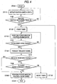
- the microcomputer 31d then performs processes for the door locking function and the door unlocking function alternately. Since the processes for operating the door locking or unlocking function have been already known, no description will be made herein. A flow chart for explaining the operation of the power window function will be described with reference to Fig. 4.
- step ST100 When electric power is supplied to the device shown in Fig. 2, the process proceeds from step ST100 to the next step ST110, and steps ST110 and ST120 that form a loop are alternately repeated until the ignition switch 56 is turned off.
- step ST130 When the driver turns the ignition switch 56 off to get off the vehicle, the process proceeds to step ST130 to start the timer 31c to perform the operation of measuring the predetermined time (timer time). The process then proceeds to step ST140 to enter a loop of steps ST140 and ST150.
- the loop of steps ST140 and ST150 is executed only during the timer time of the timer 31c, so that enable signals for enabling the power window function are supplied to the driver's seat power window controller 40, the assistant driver's seat power window controller 41, the right rear seat power window controller 42 and the left rear seat power window controller 43 respectively only during the loop. Accordingly, the driver can operate the power window function with the power window switches.
- step ST150 When a decision is made at the step ST150 that the timer time has passed, the process proceeds to the next step ST160 at which the microcomputer 31d of the main controller 31 transmits a request signal to the portable key 6.
- step ST170 the microcomputer 31d determines whether a response signal is received or not. When a response signal is not received at step ST170, the microcomputer 31d proceeds the process to step ST200.
- the ID code forming the response signal is compared with the ID code stored in the ID code memory 31b (step ST180).
- the microcomputer 31d makes a decision that the driver is still present in the cabin or its vicinity, within a communicable area, and makes a decision that the power window function may be used.
- step ST190 the process proceeds to step ST190 at which the timer 31c is reset by the microcomputer 31d.
- the process then returns to the step ST130 so that the operation is repeated until ID code check at step ST180 is disabled, that is, until the driver goes out of the communicable area.
- the microcomputer 31d of the main controller 31 makes a decision that the driver is in the communicable area of the interior antenna 48c, and extends the timer time during which the driver's seat power window controller 40, the assistant driver's seat power window controller 41, the right rear seat power window controller 42 and the left rear seat power window controller 43 can be operated. Accordingly, the driver can operate the power windows at ease and in no hurry after doing some work in the cabin.
- step ST180 results in disagreement of the received ID code with the ID code stored in the ID code memory 31b
- the process proceeds to step ST200 at which the enable signals for enabling the power window function are restrained from being supplied to the driver' s seat power window controller 40, the assistant driver' s seat power window controller 41, the right rear seat power window controller 42 and the left rear seat power window controller 43 respectively.
- the power window controllers are disabled from handling.
- the process is then terminated at the next step ST210.
- the power windows can be operated at any time only when the passenger is in the cabin, so that the passenger can work pleasantly with ease.
- an electric device mounted on a vehicle such as power windows, a car stereo system and a car navigation system can be controlled at any time when the portable key is in the cabin (when the driver is in the cabin) or its vicinity (when the driver is in a neighbor of a door of the vehicle).
- the power window can be controlled instantaneously without any loss of time when the passenger operates the power window switch.
- the embodiment has been described on the case where the extension of the timer time, which is a time period that enables the manual operation of the power windows by the driver, is performed by the microcomputer 31d.
- the timer 31c for each of the power window controllers 40, 41, 42, and 43 instead of providing the timer 31c within the main controller 31.
- the microcomputer 31d is configured to output the enable signal at predetermined intervals when the portable key 1 is located within the communicatable range and each of the power window controllers 40, 41, 42, and 43 are configured to enable the power window function for a predetermined time period when the enable signal is input from the microcomputer 31d.
- the advantage of the aforementioned embodiment can be achieved.
Abstract
Description
- The present invention relates to a wireless communication system for vehicles such as keyless entry system for remotely controlling an electric device mounted on the vehicle such as door locking/unlocking device and power window actuator, by checking on an ID code without using a key.
- In a related art, a wireless communication system for vehicles for remotely controlling an electric device mounted on the vehicle by checking on an ID code is disclosed in Japanese unexamined Patent publication JP-A-10-131569. The disclosure of the publication will be briefly described herein below.
- As shown in Figs. 5 and 6, operating switches (a
door locking switch 1a and adoor unlocking switch 1b), atransmission circuit 2a, anID code memory 2b, and anantenna 2c are provided at a grip section of aportable key 1. When either of theoperating switches transmission circuit 2a reads an ID code from theID code memory 2b. While a function code (which is set in association with the function of the switch which has been turned on) is added to the ID code, the ID code with the function code is transmitted as a radio wave from theantenna 2c to a receiver (not, shown) mounted on a vehicle. Upon receipt of the ID code and the function code, the receiver performs locking or unlocking of a door or actuates a power window function to move a glass window up or down. - That is, when either of the
operating switches portable key 1 is turned on, locking or unlocking of a door is performed by a reception circuit fixedly provided on the vehicle, in accordance with the function of the switch. - When an operation on either of the
operating switches - The device, however, has given a sense of inconvenience because the
portable key 1 is provided with theoperating switches operating keys - Under such circumstances, recently, there have been made proposals for keys without the
operating switches - Since this arrangement allows a door to be automatically locked and unlocked without need for the driver to operate a key, the driver' s both hands becomes free so that the driver can do various things freely without touching the door or the key.
- Such passive keyless entry device may be provided with the power window function. In this case, for example, arrangement may be conceived such that the power window function is enabled for a predetermined time after the driver pulls out the key from an ignition key cylinder to get off the vehicle. How to set the predetermined time to enable the power window function, however, becomes a problem in this case.
- For example, the driver becomes free to do some work with a door open for the predetermined time. Therefore, when the driver leaves the vehicle immediately after opening the door with the predetermined time set, for example, at 30 seconds, the state in which the glass window is left open continues for 30 seconds. It cannot be said that this state is preferable for security, in general.
- On the other hand, when assumed that the driver gets off the vehicle after doing some work on the seat for about 30 seconds after removing the key, and thereafter attempts to actuate the power window function to put things on the rear seat in order with the door and the glass window left open. In this case, the power window function cannot be actuated, so that it has been necessary to repeat the operation of inserting the key into the ignition key cylinder again to turn on the ignition switch.
- A possible solution to the problem may be a system in which an ID code is checked after a press on a power window switch is detected and the power window function is enabled when the check provides a positive result. The check, however, involves a certain amount of time so that timeliness is spoiled due to occurrence of a time loss before the power window is actuated. This may make the driver impatient and result in problems such as damage to salability.
- It is therefore an object of the invention to provide a wireless communication system for vehicle that extends the operating time of a power window function when an electronic key is provided with a power window control function.
- In order to achieve the object, according to one aspect of the invention, there is provided a wireless communication system for a vehicle, including: a portable transmitter-receiver adapted to communicate information wirelessly; a main controller mounted on the vehicle, the main controller adapted to communicate information wirelessly with the portable transmitter-receiver, to determine whether the portable transmitter-receiver is located within a communicatable range, and to output an enable signal when the portable transmitter-receiver is located within the communicatable range; a sub-controller mounted on the vehicle and connected to the main controller, the sub-controller adapted to enable control of a vehicle mounted electronic device when the enable signal is input from the main controller.
- When the sub-controller further includes an operation input section for controlling the vehicle mounted electronic device, and an operable time of the operation input section is extended by a predetermined time while the sub-controller continuously receives the instruction from the main controller, convenience can be improved.
- When the actuator is set as a motor for driving a power window and the operation input section is set as a power window switch, the power window can be easily used at any time even in the case where a driver has done some work after turning off the ignition switch or has done some work in the vicinity of the door left open. Accordingly, convenience can be improved.
- The above objects and advantages of the present invention will become more apparent by describing preferred exemplary embodiment thereof in detail with reference to the accompanying drawings, wherein:
- Fig. 1 is a circuit block diagram of a portable key according to one embodiment of the invention;
- Fig. 2 is a circuit block diagram of a device loaded on a vehicle for explaining a configuration of the embodiment of the invention;
- Fig. 3 is an explanatory view for explaining a configuration. of a response signal;
- Fig. 4 is a flow chart for explaining an operation of the portable key according to the embodiment shown in Fig. 2;
- Fig. 5 is an explanatory view of a portable key constituting a portable transmitter for explaining a related art; and
- Fig. 6 is a block diagram of a circuit incorporated in the portable key shown in Fig: 5.
-
- Referring now to the accompanying drawings, a description will be given in detail of a preferred embodiment of the invention.
- Fig. 1 is a circuit block diagram of a portable transmitter-receiver (hereinafter referred to as portable key) 6 as for an embodiment of the invention. Fig. 2 is a circuit block diagram of an on-
vehicle device 10 including a transmitter-receiver controller (main controller) 20 mounted on a vehicle, and a peripheral circuit (sub-controller) 30. - As shown in Fig. 1, the portable key 6 includes a
controller 7 having a microcomputer, anantenna 8 and anID code memory 9. The portable key 6 communicates with the transmitter-receiver controller 20 of the on-vehicle device 10 shown in Fig. 2 and does not include theoperating switches - The
ID code memory 9, which is a nonvolatile memory in which an ID code set uniquely to each portable key is stored, is connected to thecontroller 7. Theantenna 8 is also connected to thecontroller 7. - As shown in Fig. 2, the on-
vehicle device 10 includes amain controller 31. - The
main controller 31 includes a transmission/reception circuit 31a, anID code memory 31b, a timer (30 seconds timer) 31c, and amicrocomputer 31d. Themicrocomputer 31d generates control signals for controlling a function of locking or unlocking a driver' s seat door, an assistant driver's seat door and left and right rear seat doors. Themicrocomputer 31d also generates control signals for controlling a power window function of each of the doors to move up or down a glass window. - A driver's
seat side antenna 48a, an assistant driver'sseat side antenna 48b, and aninterior antenna 48c are connected to themain controller 31. A request signal for requesting a transmission of information such as the ID code from the portable key 6 is output from themain controller 31 to the driver'sseat side antenna 48a, the assistant driver' sseat side antenna 48b and theinterior antenna 48c. A response signal transmitted from the portable key 6 through the driver'sseat side antenna 48a, the assistant driver'sseat side antenna 48b and theinterior antenna 48c in response to the request signal is received by a built-inantenna 57 . The response signal thus received is demodulated by the transmission-reception circuit 31a and supplied to themicrocomputer 31d. - The
ID code memory 31b is made of a nonvolatile memory such as an EEPROM (Electronically Erasable and Programmable ROM) .An ID code set and registered in advance so as to be peculiar to the transmitter-receiver controller 20 is stored in theID code memory 31b (so that the ID code matches with the ID code stored in theID code memory 9 of the portable key 6). - When an
ignition switch 56 provided in a key cylinder of the vehicle is turned off as a result of a key operation by the driver, the turning-off is detected by themicrocomputer 31d. Upon the detection, themicrocomputer 31d instructs the timer 31c to start a timing operation. The transmitter-receiver controller 20 supplies thepower window controller 30 with an enable signal for enabling a power window function for a predetermined timer time. When the timer time reaches a predetermined time (e.g. 30 seconds) themicrocomputer 31d stops (or inhibits) the output of the enable signal. - As describe above, the
microcomputer 31d is connected to the transmission-reception circuit 31a for demodulating the response signal input from the portable key 6 and is connected to theID code memory 31b and the timer 31c. Themicrocomputer 31d is also connected toswitches switches power window controller 40, an assistant driver's seatpower window controller 41, a right rear seatpower window controller 42, a left rear seatpower window controller 43 andactuators 32 to 35 for locking and unlocking the doors respectively are connected to themicrocomputer 31d. - The
microcomputer 31d actuates the door locking and unlocking function that has been heretofore commonly performed to control the operations of the door locking/unlockingactuators 32 to 35. The micro-computer 31d also actuates the power window function according to the invention to control the operations of the driver's seatpower window controller 40, the assistant driver's seatpower window controller 41, the right rear seatpower window controller 42 and the left rear seatpower window controller 43. - Incidentally, the driver's
seat side antenna 48a is provided so that an area ranging from a neighbor of the driver's seat to a neighbor of the right rear seat to cover a right half of an exterior portion of the vehicle is set as a communication area. The assistant driver'sseat side antenna 48b is provided so that an area ranging from a neighbor of the assistant driver's seat to a neighbor of the left rear seat to cover a left half of the exterior portion of the vehicle is set as a communication area. Theinterior antenna 48c is provided so that an interior area of the vehicle is set as a communication area. - When the
microcomputer 31d detects that theignition switch 56 is turned off, themicrocomputer 31d supplies enable signals to the driver's seatpower window controller 40, the assistant driver's seatpower window controller 41, the right rear seatpower window controller 42 and the left rear seatpower window controller 43 respectively for the timer time decided by the timer 31c. The enable signals enable the functions of the driver's seatpower window controller 40, the assistant driver's seatpower window controller 41, the right rear seatpower window controller 42 and the left rear seatpower window controller 43 respectively. - After the enable signals are output once, and while the ID code agrees with the ID code stored in the
ID code memory 31b, themicrocomputer 31d supplies a request signal to the driver' sseat side antenna 48a, the assistant driver'sseat side antenna 48b and theinterior antenna 48c through the transmission-reception circuit 31a and sends the request signal to the portable key 6 in order to request the portable key 6 to send the ID code of the portable key 6 in a predetermined period (shorter than the timer time). - When the portable key 6 is located in the inside or vicinity of the vehicle, upon reception of the request signal, the
controller 7 of the portable key 6 transmits the response signal to the driver'sseat side antenna 48a, the assistant driver'sseat side antenna 48b and theinterior antenna 48c. When the built-inantenna 57 receives the response signal, themain controller 31 compares an ID code forming the response signal with the ID code set, registered, and stored in theID code memory 31b. When the ID code of the response signal agrees with the ID code of theID code memory 31b, themain controller 31 makes a decision that the ID code is a valid ID code, and supplies enable signals to the driver's seatpower window controller 40, the assistant driver's seatpower window controller 41, the right rear seatpower window controller 42 and the left rear seatpower window controller 43 respectively. The enable signals enable the functions of the driver' s seatpower window controller 40, the assistant driver' s seatpower window controller 41, the right rear seatpower window controller 42 and the left rear seatpower window controller 43 respectively. - Upon reception of an end-of-timer-time signal from the timer 31c when the ID codes agree with each other, the
microcomputer 31d sends another request signal to the portable key 6. The sending operation is repeated until the ID code of the response signal sent in response to the request signal disagrees from the ID code of theID code memory 31b or cannot be received, so that the timer time in the invention is extended. - When the ID code does not agree with the ID code stored in the
ID code memory 31b or cannot be received, the output of the enable signals is inhibited to disable the power window function. - The driver can operate the power windows while the
microcomputer 31d supplies the enable signals to the driver's seatpower window controller 40, the assistant driver's seatpower window controller 41, the right rear seatpower window controller 42 and the left rear seatpower window controller 43 respectively. - Incidentally, as described above, the
microcomputer 31d has the function for locking and unlocking the doors under remote radio control as a (known) function separate from the power window function. When the received ID code agrees with the registered ID code, themicrocomputer 31d determines the on/off states of theswitches actuators 32 to 35 to lock or unlock the door. No detailed description will be particularly made on the function because a lot of examples of the function have been already known. - Incidentally, the format of the response signal exchanged between the portable key 6 and the transmitter-
receiver controller 20 is constituted by serial data having sections A, B, and C (see Fig. 3). The section A is a header of the data. The section B is a peculiar ID code set for the portable key 6. The section C is a vehicle code. - When the
main controller 31 of the transmitter-receiver controller 20 supplies a request signal to the portable key 6, the portable key 6 transmits a continuous code composed of the sections A, B, and C. - In the configuration, the
microcomputer 31d then performs processes for the door locking function and the door unlocking function alternately. Since the processes for operating the door locking or unlocking function have been already known, no description will be made herein. A flow chart for explaining the operation of the power window function will be described with reference to Fig. 4. - When electric power is supplied to the device shown in Fig. 2, the process proceeds from step ST100 to the next step ST110, and steps ST110 and ST120 that form a loop are alternately repeated until the
ignition switch 56 is turned off. - When the driver turns the
ignition switch 56 off to get off the vehicle, the process proceeds to step ST130 to start the timer 31c to perform the operation of measuring the predetermined time (timer time). The process then proceeds to step ST140 to enter a loop of steps ST140 and ST150. The loop of steps ST140 and ST150 is executed only during the timer time of the timer 31c, so that enable signals for enabling the power window function are supplied to the driver's seatpower window controller 40, the assistant driver's seatpower window controller 41, the right rear seatpower window controller 42 and the left rear seatpower window controller 43 respectively only during the loop. Accordingly, the driver can operate the power window function with the power window switches. - When a decision is made at the step ST150 that the timer time has passed, the process proceeds to the next step ST160 at which the
microcomputer 31d of themain controller 31 transmits a request signal to the portable key 6. At the next step ST170, themicrocomputer 31d determines whether a response signal is received or not. When a response signal is not received at step ST170, themicrocomputer 31d proceeds the process to step ST200. - When a response signal is received at step ST170, the ID code forming the response signal is compared with the ID code stored in the
ID code memory 31b (step ST180). When these ID codes agree with each other, themicrocomputer 31d makes a decision that the driver is still present in the cabin or its vicinity, within a communicable area, and makes a decision that the power window function may be used. - As a result, the process proceeds to step ST190 at which the timer 31c is reset by the
microcomputer 31d. The process then returns to the step ST130 so that the operation is repeated until ID code check at step ST180 is disabled, that is, until the driver goes out of the communicable area. As a result, themicrocomputer 31d of themain controller 31 makes a decision that the driver is in the communicable area of theinterior antenna 48c, and extends the timer time during which the driver's seatpower window controller 40, the assistant driver's seatpower window controller 41, the right rear seatpower window controller 42 and the left rear seatpower window controller 43 can be operated. Accordingly, the driver can operate the power windows at ease and in no hurry after doing some work in the cabin. - When the check at step ST180 results in disagreement of the received ID code with the ID code stored in the
ID code memory 31b, the process proceeds to step ST200 at which the enable signals for enabling the power window function are restrained from being supplied to the driver' s seatpower window controller 40, the assistant driver' s seatpower window controller 41, the right rear seatpower window controller 42 and the left rear seatpower window controller 43 respectively. As a result, the power window controllers are disabled from handling. The process is then terminated at the next step ST210. - Although the embodiment has been described focused on power windows function by way of example, it is a matter of course that the power windows function are not necessarily essential to the invention, and that the invention may be applied to on-vehicle electronic apparatuses such as car stereo systems and car navigation systems.
- Although the embodiment has been described on the case where a request signal is sent to the portable key 6 through the driver's
seat side antenna 48a, the assistant driver'sseat side antenna 48b and theinterior antenna 48c, configuration may be made so that the request signal is sent only through theinterior antenna 48c. In the alternate configuration, there needs to be configured so that the request signal is sent only through theinterior antenna 48c when themicrocomputer 31d makes a determination on the basis of the on/off states of theignition switch 56 and theswitches - As a result, the power windows can be operated at any time only when the passenger is in the cabin, so that the passenger can work pleasantly with ease.
- According to the invention, an electric device mounted on a vehicle such as power windows, a car stereo system and a car navigation system can be controlled at any time when the portable key is in the cabin (when the driver is in the cabin) or its vicinity (when the driver is in a neighbor of a door of the vehicle).
- Since the verification of the ID code is always performed intermittently at regular time intervals to extend the operable time, the power window can be controlled instantaneously without any loss of time when the passenger operates the power window switch.
- Hereinabove, the embodiment has been described on the case where the extension of the timer time, which is a time period that enables the manual operation of the power windows by the driver, is performed by the
microcomputer 31d. However, as for an alternate configuration, it is also preferable to provide the timer 31c for each of thepower window controllers main controller 31. In the alternate configuration, themicrocomputer 31d is configured to output the enable signal at predetermined intervals when theportable key 1 is located within the communicatable range and each of thepower window controllers microcomputer 31d. In the alternate configuration, the advantage of the aforementioned embodiment can be achieved. - In the alternate configuration, it is preferable to set the time period to enable the power window function longer than the intervals of the output of the enable signal so that the power window function is assuredly enabled while the
portable key 1 is located within the communicatable range. - Although the present invention has been shown and described with reference to specific preferred embodiments, various changes and modifications will be apparent to those skilled in the art from the teachings herein. Such changes and modifications as are obvious are deemed to come within the spirit, scope and contemplation of the invention as defined in the appended claims.
Claims (7)
- A wireless communication system for a vehicle, comprising:a portable transmitter-receiver adapted to communicate information wirelessly;a main controller mounted on the vehicle, the main controller adapted to communicate information wirelessly with the portable transmitter-receiver, to determine whether the portable transmitter-receiver is located within a communicatable range, and to output an enable signal when the portable transmitter-receiver is located within the communicatable range;a sub-controller mounted on the vehicle and connected to the main controller, the sub-controller adapted to enable control of a vehicle mounted electronic device when the,enable signal is input from the main controller.
- The wireless communication system as claimed in claim 1,
wherein the sub-controller comprises an operation input section adapted to input manual operation for controlling the vehicle mounted electronic device, and
wherein the sub-controller enables controlling of the vehicle mounted electronic device based on the manual operation input by the operation input section when the enable signal is input from the main controller, and disables controlling of the vehicle mounted electronic device based on the manual operation input by the operation input section when no enable signal is input from the main controller. - The wireless communication system as claimed in claim 2,
wherein the vehicle mounted electronic device comprises a motor for driving a power window of the vehicle, and
wherein the operation input section comprises a switch for controlling the motor. - The wireless communication system as claimed in claim 2,
wherein the main controller outputs the enable signal at a predetermined intervals when the portable transmitter-receiver is located within the communicatable range, and
wherein the sub-controller enables controlling of the vehicle mounted electronic device based on the manual operation input by the operation input section for a predetermined time period when the enable signal is input from the main controller. - The wireless communication system as claimed in claim 4,
wherein the time period is longer than the intervals of the output of the enable signal. - The wireless communication system as claimed in claim 1,
wherein the information transmitted from the portable transmitter-receiver to the main controller includes an ID code set uniquely to each of the portable transmitter-receiver, and
wherein the main controller outputs the enable signal when the ID code is determined to be valid. - The wireless communication system as claimed in claim 6,
wherein the main controller transmits a request signal to the portable transmitter-receiver for requesting a transmission of the ID code in a predetermined period.
Applications Claiming Priority (2)
| Application Number | Priority Date | Filing Date | Title |
|---|---|---|---|
| JP2002256904 | 2002-09-02 | ||
| JP2002256904A JP3983634B2 (en) | 2002-09-02 | 2002-09-02 | Vehicle radio equipment |
Publications (2)
| Publication Number | Publication Date |
|---|---|
| EP1394751A2 true EP1394751A2 (en) | 2004-03-03 |
| EP1394751A3 EP1394751A3 (en) | 2004-04-28 |
Family
ID=31492705
Family Applications (1)
| Application Number | Title | Priority Date | Filing Date |
|---|---|---|---|
| EP03019929A Withdrawn EP1394751A3 (en) | 2002-09-02 | 2003-09-02 | Wireless communication system for vehicle |
Country Status (3)
| Country | Link |
|---|---|
| US (1) | US6944528B2 (en) |
| EP (1) | EP1394751A3 (en) |
| JP (1) | JP3983634B2 (en) |
Cited By (2)
| Publication number | Priority date | Publication date | Assignee | Title |
|---|---|---|---|---|
| EP1524630A1 (en) | 2003-10-15 | 2005-04-20 | Fuji Jukogyo Kabushiki Kaisha | Power window system for vehicle |
| CN106023657A (en) * | 2015-03-30 | 2016-10-12 | 国际商业机器公司 | Implementing A Restricted-Operation Region For Unmanned Vehicles |
Families Citing this family (27)
| Publication number | Priority date | Publication date | Assignee | Title |
|---|---|---|---|---|
| JP3913652B2 (en) * | 2002-09-26 | 2007-05-09 | 本田技研工業株式会社 | Electronic key system for vehicles |
| JP4121345B2 (en) * | 2002-09-27 | 2008-07-23 | 本田技研工業株式会社 | Electronic key system for vehicles |
| TWI232826B (en) * | 2002-09-30 | 2005-05-21 | Honda Motor Co Ltd | Electronic key system for vehicle |
| JP2005146529A (en) * | 2003-11-11 | 2005-06-09 | Alps Electric Co Ltd | Keyless entry system |
| JP4431876B2 (en) * | 2004-07-22 | 2010-03-17 | 三菱自動車工業株式会社 | Keyless entry device for vehicles |
| JP4460389B2 (en) * | 2004-08-17 | 2010-05-12 | 矢崎総業株式会社 | Power window device |
| US8710950B2 (en) * | 2004-12-23 | 2014-04-29 | Hill-Rom Services, Inc. | Wireless control system for a patient support apparatus |
| JP4568620B2 (en) * | 2005-02-24 | 2010-10-27 | 本田技研工業株式会社 | Electronic key system for vehicle and vehicle |
| US7749269B2 (en) * | 2005-03-28 | 2010-07-06 | Warsaw Orthopedic, Inc. | Spinal system and method including lateral approach |
| US7737838B2 (en) * | 2005-10-03 | 2010-06-15 | Gm Global Technology Operations, Inc. | Method and apparatus for transmission of wireless signals in a mobile platform |
| US7598851B2 (en) * | 2005-10-03 | 2009-10-06 | Gm Global Technology Operations, Inc. | Method and apparatus for transmitting wireless signals on a mobile platform |
| JP2007210557A (en) * | 2006-02-13 | 2007-08-23 | Mitsubishi Electric Corp | Vehicle antitheft device and vehicle antitheft method |
| JP4745180B2 (en) * | 2006-09-22 | 2011-08-10 | 川崎重工業株式会社 | Electronic key system for leisure vehicles |
| JP5003190B2 (en) * | 2007-02-13 | 2012-08-15 | 株式会社デンソー | Vehicle equipment control device |
| US7778213B2 (en) * | 2007-02-23 | 2010-08-17 | Gm Global Technology Operations, Inc. | Method and system for selectively communicating with mobile platforms |
| US20080204191A1 (en) * | 2007-02-23 | 2008-08-28 | Gm Global Technology Operations, Inc. | System and method for controlling information access on a mobile platform |
| US8527015B2 (en) * | 2007-02-23 | 2013-09-03 | GM Global Technology Operations LLC | Method and system for facilitating communication of information to a mobile platform |
| US20090328189A1 (en) * | 2008-05-05 | 2009-12-31 | Gm Global Technology Operations, Inc. | Secure wireless communication initialization system and method |
| US7916021B2 (en) * | 2008-08-13 | 2011-03-29 | Honda Motor Co., Ltd. | Smart entry system and method |
| US9095015B2 (en) * | 2008-08-19 | 2015-07-28 | Eldolab Holding B.V. | Configurable light fixture, configurable lighting system and method for configuring a lighting system |
| US7956747B2 (en) * | 2008-12-05 | 2011-06-07 | International Business Machines Corporation | Managing electrical device power state |
| US8219281B2 (en) * | 2008-12-05 | 2012-07-10 | International Business Machines Corporation | Controlling vehicle operations based on object presence |
| BRPI0910063B1 (en) * | 2009-09-03 | 2020-07-07 | Toyota Jidosha Kabushiki Kaisha. | control apparatus, control method and computer-readable medium |
| US9303442B2 (en) * | 2011-06-21 | 2016-04-05 | GM Global Technology Operations LLC | Passive verification of operator presence in handling requests for vehicle features |
| US9905067B2 (en) * | 2012-12-21 | 2018-02-27 | Continental Automotive Systems, Inc. | Automobile power window enable and disable method |
| US10781624B2 (en) | 2016-06-02 | 2020-09-22 | Felix Diaz | System and method for selectively controlling a window of a power window system of a vehicle |
| US10731620B2 (en) * | 2017-10-03 | 2020-08-04 | Polaris Industries Inc. | Battery key, starter and improved crank |
Citations (8)
| Publication number | Priority date | Publication date | Assignee | Title |
|---|---|---|---|---|
| US4240516A (en) * | 1979-01-19 | 1980-12-23 | Keycon Corporation | Vehicle securing and lockout prevention system |
| JPS56146442A (en) * | 1980-04-14 | 1981-11-13 | Nissan Motor Co Ltd | Power window controller for vehicle |
| US5381065A (en) * | 1992-04-08 | 1995-01-10 | Jones; Thomas | Vehicle window and lock securement |
| US5698907A (en) * | 1995-01-26 | 1997-12-16 | Weber; Harold J. | Motor vehicle electric window control and closure override method and apparatus |
| EP0886025A2 (en) * | 1997-06-20 | 1998-12-23 | Rover Group Limited | Vehicle closure systems |
| EP0965710A2 (en) * | 1998-06-18 | 1999-12-22 | Toyota Jidosha Kabushiki Kaisha | Vehicle control system |
| EP1079053A2 (en) * | 1999-08-27 | 2001-02-28 | Toyota Jidosha Kabushiki Kaisha | Vehicle automatic door-locking system using identifier signal transmitting portable unit |
| EP1099812A2 (en) * | 1999-11-09 | 2001-05-16 | Mazda Motor Corporation | Opening-closing member control apparatus for vehicle |
Family Cites Families (5)
| Publication number | Priority date | Publication date | Assignee | Title |
|---|---|---|---|---|
| JPH10131569A (en) | 1996-11-01 | 1998-05-19 | Nissan Motor Co Ltd | Keyless entry device |
| US5751073A (en) * | 1996-11-20 | 1998-05-12 | General Motors Corporation | Vehicle passive keyless entry and passive engine starting system |
| JPH10292702A (en) * | 1997-04-21 | 1998-11-04 | Aisin Seiki Co Ltd | Door proximity communication device and door lock controller |
| JPH112053A (en) * | 1997-06-12 | 1999-01-06 | Nippon Soken Inc | Passive entry control system for vehicle |
| US6359348B1 (en) * | 1999-11-15 | 2002-03-19 | Lear Corporation | Semi-passive keyless entry method and device |
-
2002
- 2002-09-02 JP JP2002256904A patent/JP3983634B2/en not_active Expired - Lifetime
-
2003
- 2003-08-12 US US10/638,536 patent/US6944528B2/en not_active Expired - Fee Related
- 2003-09-02 EP EP03019929A patent/EP1394751A3/en not_active Withdrawn
Patent Citations (8)
| Publication number | Priority date | Publication date | Assignee | Title |
|---|---|---|---|---|
| US4240516A (en) * | 1979-01-19 | 1980-12-23 | Keycon Corporation | Vehicle securing and lockout prevention system |
| JPS56146442A (en) * | 1980-04-14 | 1981-11-13 | Nissan Motor Co Ltd | Power window controller for vehicle |
| US5381065A (en) * | 1992-04-08 | 1995-01-10 | Jones; Thomas | Vehicle window and lock securement |
| US5698907A (en) * | 1995-01-26 | 1997-12-16 | Weber; Harold J. | Motor vehicle electric window control and closure override method and apparatus |
| EP0886025A2 (en) * | 1997-06-20 | 1998-12-23 | Rover Group Limited | Vehicle closure systems |
| EP0965710A2 (en) * | 1998-06-18 | 1999-12-22 | Toyota Jidosha Kabushiki Kaisha | Vehicle control system |
| EP1079053A2 (en) * | 1999-08-27 | 2001-02-28 | Toyota Jidosha Kabushiki Kaisha | Vehicle automatic door-locking system using identifier signal transmitting portable unit |
| EP1099812A2 (en) * | 1999-11-09 | 2001-05-16 | Mazda Motor Corporation | Opening-closing member control apparatus for vehicle |
Non-Patent Citations (1)
| Title |
|---|
| PATENT ABSTRACTS OF JAPAN vol. 006, no. 029 (M-113), 20 February 1982 (1982-02-20) & JP 56 146442 A (NISSAN MOTOR CO LTD), 13 November 1981 (1981-11-13) * |
Cited By (3)
| Publication number | Priority date | Publication date | Assignee | Title |
|---|---|---|---|---|
| EP1524630A1 (en) | 2003-10-15 | 2005-04-20 | Fuji Jukogyo Kabushiki Kaisha | Power window system for vehicle |
| US7221065B2 (en) | 2003-10-15 | 2007-05-22 | Fuji Jukogyo Kabushiki Kaisha | Power window system for vehicle |
| CN106023657A (en) * | 2015-03-30 | 2016-10-12 | 国际商业机器公司 | Implementing A Restricted-Operation Region For Unmanned Vehicles |
Also Published As
| Publication number | Publication date |
|---|---|
| JP3983634B2 (en) | 2007-09-26 |
| US6944528B2 (en) | 2005-09-13 |
| JP2004092257A (en) | 2004-03-25 |
| US20040043802A1 (en) | 2004-03-04 |
| EP1394751A3 (en) | 2004-04-28 |
Similar Documents
| Publication | Publication Date | Title |
|---|---|---|
| US6944528B2 (en) | Wireless communication system for vehicle | |
| KR100638388B1 (en) | Keyless entry device | |
| US7612650B2 (en) | Remote control system and method | |
| KR100766189B1 (en) | Vehicle door control system and method | |
| JP4528587B2 (en) | Portable machine | |
| JP5425446B2 (en) | Smart keyless entry system | |
| EP3330136B1 (en) | Vehicle control system | |
| JP4022859B2 (en) | Door lock control device | |
| US20100050713A1 (en) | Door lock control apparatus for vehicle | |
| JPH08246728A (en) | Keyless entry device | |
| JP5436587B2 (en) | Electronic key device and base unit used for electronic key device | |
| JP5343552B2 (en) | Keyless entry system | |
| JP4525366B2 (en) | Smart keyless device for vehicles | |
| CN109642439B (en) | Electronic key system | |
| US20090240385A1 (en) | Electronic control apparatus for vehicle | |
| JP5451128B2 (en) | Keyless entry device for vehicles | |
| JP4585961B2 (en) | Wireless communication control system | |
| JP4539513B2 (en) | Remote control device for vehicle | |
| JP5462142B2 (en) | Electronic key system | |
| JPH1193485A (en) | Vehicle remote-control device and its system | |
| WO2015104748A1 (en) | Auto lock system | |
| KR100749606B1 (en) | Vehicle device control system, unit on the vehicle and portable device | |
| JP3815598B2 (en) | Wireless door lock device | |
| JP5161476B2 (en) | Smart entry system for vehicles | |
| JP2005273329A (en) | Radio type door locking-unlocking device and method |
Legal Events
| Date | Code | Title | Description |
|---|---|---|---|
| PUAI | Public reference made under article 153(3) epc to a published international application that has entered the european phase |
Free format text: ORIGINAL CODE: 0009012 |
|
| AK | Designated contracting states |
Kind code of ref document: A2 Designated state(s): AT BE BG CH CY CZ DE DK EE ES FI FR GB GR HU IE IT LI LU MC NL PT RO SE SI SK TR |
|
| AX | Request for extension of the european patent |
Extension state: AL LT LV MK |
|
| PUAL | Search report despatched |
Free format text: ORIGINAL CODE: 0009013 |
|
| AK | Designated contracting states |
Kind code of ref document: A3 Designated state(s): AT BE BG CH CY CZ DE DK EE ES FI FR GB GR HU IE IT LI LU MC NL PT RO SE SI SK TR |
|
| AX | Request for extension of the european patent |
Extension state: AL LT LV MK |
|
| 17P | Request for examination filed |
Effective date: 20040721 |
|
| 17Q | First examination report despatched |
Effective date: 20041019 |
|
| AKX | Designation fees paid |
Designated state(s): DE FR GB |
|
| STAA | Information on the status of an ep patent application or granted ep patent |
Free format text: STATUS: THE APPLICATION IS DEEMED TO BE WITHDRAWN |
|
| 18D | Application deemed to be withdrawn |
Effective date: 20100401 |