EP1400894A2 - Storage controller - Google Patents
Storage controller Download PDFInfo
- Publication number
- EP1400894A2 EP1400894A2 EP03021100A EP03021100A EP1400894A2 EP 1400894 A2 EP1400894 A2 EP 1400894A2 EP 03021100 A EP03021100 A EP 03021100A EP 03021100 A EP03021100 A EP 03021100A EP 1400894 A2 EP1400894 A2 EP 1400894A2
- Authority
- EP
- European Patent Office
- Prior art keywords
- data
- cache memory
- control unit
- channel control
- storing
- Prior art date
- Legal status (The legal status is an assumption and is not a legal conclusion. Google has not performed a legal analysis and makes no representation as to the accuracy of the status listed.)
- Withdrawn
Links
Images


Classifications
-
- G—PHYSICS
- G06—COMPUTING; CALCULATING OR COUNTING
- G06F—ELECTRIC DIGITAL DATA PROCESSING
- G06F11/00—Error detection; Error correction; Monitoring
- G06F11/07—Responding to the occurrence of a fault, e.g. fault tolerance
- G06F11/16—Error detection or correction of the data by redundancy in hardware
- G06F11/20—Error detection or correction of the data by redundancy in hardware using active fault-masking, e.g. by switching out faulty elements or by switching in spare elements
- G06F11/2097—Error detection or correction of the data by redundancy in hardware using active fault-masking, e.g. by switching out faulty elements or by switching in spare elements maintaining the standby controller/processing unit updated
-
- G—PHYSICS
- G06—COMPUTING; CALCULATING OR COUNTING
- G06F—ELECTRIC DIGITAL DATA PROCESSING
- G06F11/00—Error detection; Error correction; Monitoring
- G06F11/07—Responding to the occurrence of a fault, e.g. fault tolerance
- G06F11/16—Error detection or correction of the data by redundancy in hardware
- G06F11/20—Error detection or correction of the data by redundancy in hardware using active fault-masking, e.g. by switching out faulty elements or by switching in spare elements
- G06F11/2053—Error detection or correction of the data by redundancy in hardware using active fault-masking, e.g. by switching out faulty elements or by switching in spare elements where persistent mass storage functionality or persistent mass storage control functionality is redundant
- G06F11/2089—Redundant storage control functionality
-
- G—PHYSICS
- G06—COMPUTING; CALCULATING OR COUNTING
- G06F—ELECTRIC DIGITAL DATA PROCESSING
- G06F12/00—Accessing, addressing or allocating within memory systems or architectures
- G06F12/02—Addressing or allocation; Relocation
- G06F12/08—Addressing or allocation; Relocation in hierarchically structured memory systems, e.g. virtual memory systems
- G06F12/0802—Addressing of a memory level in which the access to the desired data or data block requires associative addressing means, e.g. caches
- G06F12/0866—Addressing of a memory level in which the access to the desired data or data block requires associative addressing means, e.g. caches for peripheral storage systems, e.g. disk cache
-
- G—PHYSICS
- G06—COMPUTING; CALCULATING OR COUNTING
- G06F—ELECTRIC DIGITAL DATA PROCESSING
- G06F2212/00—Indexing scheme relating to accessing, addressing or allocation within memory systems or architectures
- G06F2212/31—Providing disk cache in a specific location of a storage system
- G06F2212/312—In storage controller
Definitions
- the present invention relates to a storage control apparatus, a storage system, a control method of the storage control apparatus, and a channel control unit.
- various devices have hitherto been used to improve the access speed of large-capacity storage devices employing magnetic disks as their storage media.
- disposing a cache memory, which uses a semiconductor device as its storage medium, inside a storage control apparatus for controlling accesses to a storage device has been practiced. Thereby, once data has been read out from a magnetic disk, write/read can be carried out to the cache memory. Therefore, the access speed can be improved.
- configuration is such that a channel control unit for controlling input/output to a host computer and a disk control unit for controlling input/output to a storage device are connected via a network, with a cache memory being deployed on the network.
- the cache memory is often duplicated providing for loss of data.
- cache memories were deployed in a distributed manner (Refer to Japanese Patent Application Laid-open Publication No. 11-203201 for example).
- the concentration of accesses to a cache memory can be alleviated by the distributed deployment of cache memories, paths on a data-path switch compete and this can be a factor for preventing the improvement of the performance of access when a multiplicity of accesses occur simultaneously since the accesses to the cache memories are made through the data-path switch (the network connecting the channel control unit and the disk control unit).
- One object of the invention is to provide a storage control apparatus for enabling accesses to data to be made at a higher speed.
- One aspect of the invention in order to achieve the above object provides a storage control apparatus including a plurality of channel control units each having an interface with an information processor, the storage control apparatus comprising a disk control unit having an interface with a storage device for storing data; a cache memory for storing temporarily data to be interchanged between the information processor and the storage device; and an internal connector unit connecting the channel control units and the disk control unit to each other. Furthermore, the cache memory is deployed in the channel control units that are connected to one another through a dedicated data transfer path used for storing mutually the data stored in the cache memory.
- An aspect of the present invention provides a storage control apparatus including a plurality of channel control units each having an interface with an information processor; and a disk control unit having an interface with a storage device for storing data; the storage control apparatus comprising cache memories for storing temporarily data to be interchanged between the information processor and the storage device; and an internal connector unit for connecting mutually the plurality of channel control units and the disk control unit, wherein the cache memories are connected to one another through a dedicated data transfer path used for storing mutually the data stored in the cache memories.
- the activity ratio of the internal connector unit can be suppressed since the data transfer for the data duplication between the cache memories is executed without using the internal connector unit. Therefore, the data competition in the internal connector unit is alleviated and the access speed of the data accesses to the information processors can be made higher. Furthermore, the data duplication process can be executed in a brief period of time since each pair of cache memories paired for duplicating data are connected to each other within the respective pair through a dedicated data transfer path. Therefore, a data access completion acknowledgement can be sent to the information processor in a brief period of time and the access speed can be made higher.
- maintenance and management of the channel control units can be carried out without influencing the operation of the storage control apparatus by duplicating data stored in a cache memory mutually between the paired channel control units within each pair. For example, since data stored in the cache memory of a channel control unit is also stored in the other channel control unit paired therewith, replacing of the channel control unit can be carried out without saving the data stored in the cache memory onto other storage area than that in the channel control unit. Thus, it is possible to carry out the maintenance and management operation of the storage control apparatus that is required to continuously operate for 24 hours and 365 days without stopping its operation and degrading its functions.
- the information processor can access the data at a high access speed since a cache memory is arranged in the a channel control unit.
- the data competition in the internal connector unit can be alleviated since these accesses do not pass through the internal connector unit.
- a storage control apparatus including a channel control unit having an interface with an information processor; a disk control unit having an interface with a storage device for storing data; a first and a second cache memories for storing temporarily data to be interchanged between the information processor and the storage device; and an internal connector unit for connecting the channel control unit and the disk control unit to each other, wherein the first cache memory is disposed in the channel control unit, and wherein the second cache memory is disposed in the internal connector unit.
- Still another aspect of the present invention provides a storage control apparatus including a plurality of channel control units each having an interface with an information processor; a disk control unit having an interface with a storage device for storing data; and a first and a second cache memories for storing temporarily data to be interchanged between the information processor and the storage device; and an internal connector unit for connecting mutually the plurality of channel control units and the disk control unit, wherein the first cache memory is disposed in each of the plurality of channel control units that are connected to one another through a dedicated data transfer path used for storing mutually the data stored in the first cache memories, and wherein a couple of the second cache memories for storing mutually the same data are connected to the internal connector unit.
- the activity ratio of the internal connector unit can be suppressed since data transfer between the first cache memories for duplication of data is executed without using the internal connector unit. Therefore, the data competition in the internal connector unit can be alleviated and the speed of accesses to the data in the information processor can be made higher. Furthermore, the data duplication process can be executed in a brief period of time since each pair of the first cache memories paired for duplicating of data are connected to each other within the respective pair through a dedicated data transfer path.
- a data access completion acknowledgement can be sent to the information processor in a brief period of time and the access speed can bemade higher. Furthermore, maintenance and management of the channel control units can be carried out without influencing the operation of the storage control apparatus by duplicating the data stored in a cache memory mutually between the paired channel control units within each pair.
- the information processor can access the data at a high access speed since the first cache memory is arranged in the channel control unit.
- the data competition in the internal connector unit can be alleviated since these accesses do not pass through the internal connector unit.
- access speed from an information processor to data can be made higher.
- Yet another aspect of the present invention is provided with the storage control apparatus and the storage device.
- Still yet another aspect of the present invention provides a method for writing data to a cache memory by a channel control unit for the case where a data write-in request is issued from an information processor to a storage control apparatus, the storage control apparatus including a plurality of the channel control units each having an interface with the information processor; a disk control unit having an interface with a storage device for storing data; the cache memory for storing temporarily data to be interchanged between the information processor and the storage device, the cache memory being disposed in each of the plurality of channel control units that are connected to one another through a dedicated data transfer path used for storing mutually the data temporarily stored; and an internal connector unit for connecting mutually the plurality of channel control units and the disk control unit, the method for writing comprising the steps of receiving data to be written from the information processor; writing the data to be written to the cache memory; transmitting the data to be written through the dedicated data transfer path to the other channel control unit connected to each other through the dedicated data transfer path; receiving through the dedicated data transfer path an acknowledgement notifying that writing of the transmitted data to the
- the activity ratio of the internal connector unit can be suppressed since the data transfer for the data duplication between the cache memories is executed without using the internal connector unit. Therefore, the data competition in the internal connector unit can be alleviated and the access speed of the data accesses to the information processors can be made higher. Furthermore, the data duplication process can be executed in a brief period of time since each pair of cache memories paired for duplicating of data are connected to each other within the respective pair through a dedicated data transfer path. Therefore, a data access completion acknowledgement can be sent to the information processor in a brief period of time and the access speed can be made higher.
- maintenance and management of the channel control units can be carried out without influencing the operation of the storage control apparatus by duplicating data stored in a cache memory mutually between the paired channel control units within each pair. For example, since data stored in the cache memory of a channel control unit is also stored in the other channel control unit paired therewith, replacing of the channel control unit can be carried out without saving the data stored in the cache memory onto other storage area than that in the channel control unit. Thus, it is possible to carry out the maintenance and management operation of the storage control apparatus that is required to continuously operate for 24 hours and 365 days without stopping its operation and degrading its functions.
- Yet still another aspect of the present invention provides a method for reading in data stored in a second cache memory to a first cache memory by a channel control unit in a storage control apparatus, the storage control apparatus including a plurality of the channel control units each having an interface with an information processor; a disk control unit having an interface with a storage device for storing data; the first cache memory for storing temporarily data to be interchanged between the information processor and the storage device, the first cache memory being disposed in each of the plurality of channel control units that are connected to one another through a dedicated data transfer path used for storing mutually the data temporarily stored; a couple of the second cache memories for storing the same data mutually; and an internal connector unit for connecting mutually the plurality of channel control units, the disk control unit and the couple of second cache memories, the method for reading in comprising the steps of transmitting a read-in command of the data to the second cache memory; acquiring the data from the second cache memory; writing the acquired data to the first cache memory; transmitting the acquired data through the dedicated data transfer path to the other channel
- the activity ratio of the internal connector unit can be suppressed since data transfer between the first cache memories for duplicating of data is executed without using the internal connector unit. Therefore, the data competition in the internal connector unit can be alleviated and the speed of accesses to the data in the information processor can be made higher. Furthermore, the reliability of data can be improved since the data read out from a second cache memory is written in two (2) first cache memories in a duplicated manner. Furthermore, maintenance and management of the channel control units can be carried out without influencing the operation of the storage control apparatus by duplicating data stored in a cache memory mutually between the paired channel control units within each pair.
- a further aspect of the present invention provides a method for reading out data by a channel control unit for the case where a data read-out request is issued from an information processor to a storage control apparatus, the storage control apparatus including a plurality of the channel control units each having an interface with the information processor; a disk control unit having an interface with a storage device for storing data; a first cache memory for storing temporarily data to be interchanged between the information processor and the storage device, the first cache memory being disposed in each of the plurality of channel control units connected to one another through a dedicated data transfer path used for storing mutually the data temporarily stored; a couple of second cache memories for storing the same data mutually; and an internal connector unit for connecting mutually the plurality of channel control units, the disk control unit and the couple of second cache memories, the method for reading out comprising the steps of receiving from the information processor a read-out command for data for which the address is specified; determining whether the data at the specified address is stored in the first cache memory; transmitting a read-in command of the data to the second
- the data when data is requested to be read out from an information processor, in a case where the data is not stored in a first cache memory, the data can be sent to the information processor without accessing to the storage device if the data is stored in a second cache memory. Furthermore, the data having been read out from the second memory is written in two (2) first cache memories in a duplicated manner. Therefore, the next or later accesses can be responded with the data on the first cache memory.
- the activity ratio of the internal connector unit can be suppressed since the duplication of data between first cache memories is executed through dedicated data transfer paths and the internal connector unit is not used. Therefore, the data competition in the internal connector unit is alleviated and the speed of accesses to data in the information processors can be made higher. Furthermore, since the data on the first cache memories is stored in a duplicated manner, the reliability of the data can be improved.
- maintenance and management of the channel control units can be carried out without influencing the operation of the storage control apparatus since this duplication is effected between the paired channel control units. For example, since data stored in the cache memory of a certain channel control unit is also stored in the other channel control unit to be paired therewith, replacing of the channel control unit can be carried out without saving the data stored in the cache memory onto other storage area than that in the channel control unit. Thus, it is possible to carry out the maintenance and management operation of the storage control apparatus that is required to continuously operate for 24 hours and 365 days without stopping its operation and degrading its functions.
- a still further aspect of the present invention provides a method for writing out data stored in a first cache memory to a second cache memory by a channel control unit in a storage control apparatus, the storage control apparatus including a plurality of the channel control units each having an interface with an information processor; a disk control unit having an interface with a storage device for storing data; the first cache memory for storing temporarily data to be interchanged between the information processor and the storage device, the first cache memory being disposed in each of the plurality of channel control units connected to one another through a dedicated data transfer path used for storing mutually the data temporarily stored; a couple of the second cache memories for storing the same data mutually; and an internal connector unit for connecting mutually the plurality of channel control units, the disk control unit and the couple of second cache memories, the method for writing out comprising the steps of selecting the data to be written out to the second cache memory among the data stored in the first cache memory; securing a storage area to write in the selected data to the second cache memory; and transmitting the selected data to the second cache memory.
- the storage area on the first cache memory where the data is stored can bemadeopen. Since there are no secondmemories conventionally, any storage area on the first cache memories can not be made open until the data to be replaced is written in a storage device. According to this aspect of implementation, it is possible to execute a replacing process of a cache memory in a brief period of time.
- the selection is preferably carried out by selecting data that has not been accessed for the longest period of time.
- a yet further aspect of the present invention provides a method for storing by a storage control apparatus into a storage device data stored in a first cache memory and in a second cache memory for the case where power supply to the storage control apparatus is interrupted, the storage control apparatus including a plurality of channel control units each having an interface with an information processor; a disk control unit having an interface with the storage device for storing data; the first cache memory for storing temporarily data to be interchanged between the information processor and the storage device, the first cache memory being disposed in each of the plurality of channel control units connected to one another through a dedicated data transfer path used for storing mutually the data temporarily stored; a couple of the second cache memories for storing the same data mutually; and an internal connector unit for connecting mutually the plurality of channel control units, the disk control unit and the couple of second cache memories, the method for storing comprising the steps of switching the power source to a battery provided in advance in the storage control apparatus; writing to the second cache memory data stored in the first cache memory that has been updated by the information processor and that has not yet
- a still yet further aspect of the present invention provides a channel control unit in a storage control apparatus including a plurality of the channel control units each having an interface with an information processor; a disk control unit having an interface with a storage device for storing data; and a cache memory for storing temporarily data to be interchanged between the information processor and the storage device, the channel control unit comprising an internal connector unit for connecting mutually the cache memory, the plurality of channel control units and the disk control unit, the cache memory being disposed in each of the plurality of channel control units connected to one another through a dedicated data transfer path used for storing mutually the stored data; means for receiving data to be written from the information processor; means for writing the data to be written to the cache memory; means for transmitting the data to be written through the dedicated data transfer path to the other channel control unit connected to each other through the dedicated data transfer path; means for receiving from the other channel control unit through the dedicated data transfer path an acknowledgement notifying that the writing of the transmitted data to the cache memory disposed in the other channel control unit has been completed; and means for transmitting
- a yet still further aspect of the present invention provides a channel control unit in a storage control apparatus including a plurality of the channel control units each having an interface with the information processor; a disk control unit having an interface with a storage device for storing data; a first cache memory for storing temporarily data to be interchanged between the information processor and the storage device, the first cache memory being disposed in each of the plurality of channel control unit connected to one another by a dedicated data transfer path used for storing mutually the data temporarily stored; a couple of second cache memories for storing the same data mutually; and an internal connector unit for connecting mutually the plurality of channel control units, the disk control unit and the couple of second cache memories, the channel control unit comprising means for transmitting to the second cache memory a read-in command for data stored in the second cache memory; means for acquiring the data from the second cache memory; means for writing the acquired data to the first cache memory; means for transmitting the acquired data through the dedicated data transfer path to the other channel control unit connected to each other through the dedicated data transfer path; and means for receiving from
- a further aspect of the present invention provides a channel control unit in a storage control apparatus including a plurality of the channel control units each having an interface with an information processor; a disk control unit having an interface with a storage device for storing data; a first cache memory for storing temporarily data to be interchanged between the information processor and the storage device, the first cache memory being disposed in each of the plurality of channel control units connected to one another through a dedicated data transfer path used for storing mutually the data temporarily stored; a couple of second cache memories for storing the same data mutually; and an internal connector unit for connecting mutually the plurality of channel control units, the disk control unit and the couple of second cache memories, the channel control unit comprising means for receiving from the information processor a read-out command for data for which the address is specified; means for determining whether the data at the specified address is stored in the first cache memory; means for transmitting the read-in command for the data to the second cache memory if the data at the specified address is not stored in the first cache memory; means for acquiring the data from the second cache
- a further aspect of the present invention provides a channel control unit in a storage control apparatus including a plurality of the channel control units each having an interface with an information processor; a disk control unit having an interface with a storage device for storing data; a first cache memory for storing temporarily data to be interchanged between the information processor and the storage device, the first cache memory being disposed in each of the plurality of channel control units connected to one another through a dedicated data transfer path used for storing mutually the data temporarily stored; a couple of second cache memories for storing the same data mutually; and an internal connector unit for connecting mutually the plurality of channel control units, the disk control unit and the couple of second cache memories, the channel control unit comprising means for selecting the data to be written out to the second cache memory among data stored in the first cache memory; means for securing a storage area to write in the selected data to the second cache memory; and means for transmitting the selected data to the second cache memory.
- the selection is preferably carried out by selecting the data that has not been accessed for the longest period of time.
- a further aspect of the present invention provides a storage control apparatus including a plurality of channel control units each having an interface with an information processor; a disk control unit having an interface with a storage device for storing data; a first cache memory for storing temporarily data to be interchanged between the information processor and the storage device, the first cache memory being disposed in each of the plurality of channel control units connected to one another through a dedicated data transfer path used for storing mutually the data temporarily stored; a couple of second cache memories for storing the same data mutually; and an internal connector unit for connecting mutually the plurality of channel control units, the disk control unit and the second cache memories, the storage control apparatus comprising a battery for continuously supplying power when supply of power to the storage control apparatus is interrupted; means for switching the power source to the battery when supply of power to the storage control apparatus is interrupted; means for writing to the second cache memory data stored in the first cache memory that has been updated by the information processor and that has not yet been written in to the second cache memory; means for reducing the supply of power from the battery to the channel control unit
- a further aspect of the present invention relates to a program for causing a channel control unit in a storage control apparatus including a plurality of the channel control units each having an interface with the information processor; a disk control unit having an interface with a storage device for storing data; a cache memory for storing temporarily data to be interchanged between the information processor and the storage device, the cache memory being disposed in each of the plurality of channel control units connected to one another through a dedicated data transfer path used for storing mutually the data temporarily stored; and an internal connector unit for connecting mutually the plurality of channel control units and the disk control unit to execute the steps of receiving data to be written from the information processor; writing the data to be written to the cache memory; transmitting the data to be written through the dedicated data transfer path to the other channel control unit connected to each other through the dedicated data transfer path; receiving from the other channel control unit through the dedicated data transfer path an acknowledgement notifying that the writing of the transmitted data to the cache memory disposed in the other channel control unit has been completed; and transmitting to the information processor an acknowledgement notifying
- a further aspect of the present invention relates to a program for causing a channel control unit in a storage control apparatus including a plurality of the channel control units each having an interface with an information processor; a disk control unit having an interface with a storage device for storing data; a first cache memory for storing temporarily data to be interchanged between the information processor and the storage device, the first cache memory being disposed in each of the plurality of channel control units connected to one another through a dedicated data transfer path used for storing mutually the data temporarily stored; a couple of second cache memories for storing the same data mutually; and an internal connector unit for connecting mutually the plurality of channel control units, the disk control unit and the couple of second cache memories to execute the steps of transmitting to the second cache memory a read-in command for data stored in the second cache memory; acquiring the data from the second cache memory; writing the acquired data to the first cache memory; transmitting the acquired data through the dedicated data transfer path to the other channel control unit connected to each other through the dedicated data transfer path; and receiving from the other channel control unit an
- a further aspect of the present invention relates to a program for causing a channel control unit in a storage control apparatus including a plurality of channel control units each having an interfacewith an information processor; a disk control unit having an interface with a storage device for storing data; a first cache memory for storing temporarily data to be interchanged between the information processor and the storage device, the first cache memory being disposed in each of the plurality of channel control units connected to one another through a dedicated data transfer path used for storing mutually the data temporarily stored; a couple of second cache memories for storing the same data mutually; and an internal connector unit for connecting mutually the plurality of channel control units, the disk control unit and the couple of second cache memories to execute the steps of receiving from the information processor a read-out command for data for which the address is specified; determining whether the data at the specified address is stored in the first cache memory; transmitting a read-in command for the data at the specified address to the first cache memory if the data is not stored in the first cache memory; acquiring the data from the second cache memory;
- a further aspect of the present invention relates to a program for causing a channel control unit in a storage control apparatus including a plurality of channel control units each having an interface with an information processor; a disk control unit having an interface with a storage device for storing data; a first cache memory for storing temporarily data to be interchanged between the information processor and the storage device, the first cache memory being disposed in each of the plurality of channel control units connected to one another through a dedicated data transfer path used for storing mutually the data temporarily stored; a couple of second cache memories for storing the same data mutually; and an internal connector unit for connecting mutually the plurality of channel control units, the disk control unit and the couple of second cache memories to execute the steps of selecting data to be written out to the second cache memory among data stored in the first cache memory; securing a storage area to write the selected data to the second cache memory; and transmitting the selected data to the second cache memory.
- the selection is preferably carried out by selecting the data that has not been accessed for the longest period of time.
- a further aspect of the present invention relates to a program for causing a storage control apparatus including a plurality of channel control units each having an interface with an information processor; a disk control unit having an interface with a storage device for storing data; a first cache memory for storing temporarily data to be interchanged between the information processor and the storage device, the first cache memory being disposed in each of the plurality of channel control units connected to one another through a dedicated data transfer path used for storing mutually the data temporarily stored; a couple of second cache memories for storing the same data mutually; and an internal connector unit for connecting mutually the plurality of channel control units, the disk control unit and the couple of second cache memories to execute the steps of switching the power source to a battery for continuously supplying power to the storage control apparatus when the supply of power to the storage control apparatus is interrupted; writing to the second cache memory data stored in the first cache memory that has been updated by the information processor and that has not yet been written into the second cache memory; reducing the amount of power supplied from the battery to the channel control unit after completion of the writing to
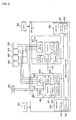
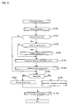
- Fig. 1 is a block diagram showing the entire configuration of a computer system according to a first example.
- a disk control apparatus (storage control apparatus) 100 is connected to four host computers (information processors) 200 and receives requests for reading/writing of data. Access routes between each host computer 200 and the disk control apparatus 100 are duplexed and adapted such that one same host computer 200 is connected to different channel control units 300. By adapting in this manner, when a fault occurs on one access route, a disk access process can be continued on the other access route.
- a channel control unit 3 0 0 comprises host interface control units 310 and has an interface function with the host computers 200.
- the channel control unit 300 also comprises a cache control unit 320 and a local cache (a first cache memory) 330, and strives for realizing disk accesses at a higher speed by storing temporarily the data read out from a storage device 800.
- the cache control unit 320 is mutually connected with a cache control unit 320 of another channel control unit 300 paired with the channel control unit 300 through a between-pair connection unit 350, and executes duplication of data by mutually storing data in each other's local cache 330.
- the channel control unit 300 comprises an internal interface control unit 340 and is connected with global caches (second cache memories) 600 and disk control units 400 through an internal connector unit 500.
- global caches second cache memories
- a disk control unit 400 has an interface function for connecting with storage devices 800. Data read out from a storage device 800 by a disk control unit is stored in a data area in a global cache 600 through the internal connector unit 500 and, then, stored in a data area 331 in a local cache 330 through an internal interface control unit 340 and a cache control unit 320 in a channel control unit 300.
- Two global caches 600 are provided and strive for duplicating of data by storing mutually the data stored by each other.
- the disk control apparatus 100 secures a power source for emergency using a battery 700. Therefore, even when the supply of power to the disk control apparatus 100 is terminated due to a power-down, the disk control apparatus 100 can write the data stored in the local cache 330 and the global cache 600, into a storage device 800 while it is powered by the battery 700. Therefore, the data stored in the local cache 330 and the global cache 600 is prevented from being lost.
- Fig. 2 is a block diagram showing the entire configuration of a computer system according to another embodiment of the computer system shown in Fig. 1.
- a control unit 900 comprises a host interface control unit 910 working as an interface with a host computer 200 and a disk interface control unit 960 working as an interface with storage devices 800.
- Fig. 1 The configuration shown in Fig. 1 is adapted such that the cost reduction effect is maximal in the largest-scaled system assuming that the scale of the system is largest, and is suitable for large-scale configurations. Therefore, this configuration is effective for a case where a customer whose business has been already stable realizes a relatively large configuration.
- the configuration shown in Fig. 1 is adapted such that the cost reduction effect is maximal in the largest-scaled system assuming that the scale of the system is largest, and is suitable for large-scale configurations. Therefore, this configuration is effective for a case where a customer whose business has been already stable realizes a relatively large configuration.
- data read out from a storage device 800 by a disk control unit 960 is stored in a data area 931 of a local cache through a cache control unit 920. Therefore, read-out at a high speed is enabled since the data do not pass through internal connector units 500 or global caches 600.
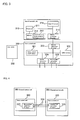
- Fig. 3 is a block diagram showing the configuration of a host interface control unit 310 and a cache control unit 320.
- the host control unit 310 comprises a processor 311, a memory 312, a host interface circuit 314 and an internal connection interface circuit 315.
- a processor 311 receives requests for reading/writing of data from a host computer 200 by executing a control program 313 stored in a memory 312, and controls a disk control apparatus 100.
- the host interface circuit 314 is connected to the host computer 200 and constitutes a circuit for sending/receiving data.
- the internal connection interface circuit 315 constitutes a circuit for connecting with the cache control unit 320.
- the cache control unit 320 comprises a cache control unit interface circuit 321, a buffer memory 322, an internal connection interface circuit 323 and 324, and a between-paired-caches interface circuit 325.
- the cache control unit interface circuit 321 constitutes a circuit for connecting with the local cache 330 and controls the sending to/receiving from the local cache 330.
- the buffer memory 322 is used for storing data temporarily when data is sent to/received from the local cache 330.
- the internal connection interface circuit 323 constitutes a circuit for connecting with the host interface control unit 310.
- the internal connection interface circuit 324 constitutes a circuit for connecting with the internal interface control unit 340.
- the between-paired-caches interface circuit 325 is connected with the cache control unit 320 of a channel control unit 300 to be paired therewith.
- the mode of connection is shown in Fig. 4.
- the channel control unit 300 to be paired therewith executes the duplication of data by sharing the data in each other's local cache 330 . Commands and data for executing the duplication of data are sent to the channel control unit 300 of the other one of the pair.
- the between-paired-caches interface circuits 325 within a pair are connected directly with each other by a between-paired-caches connection unit 350.
- the between-paired-caches connection unit 350 is a communication path provided dedicatedly for duplicating data in each other's local cache 330 within the pair. Therefore, data duplication can be executed at a high speed since data communication between the paired local caches 330 can be executed without being influenced by other processes.
- the configurations of circuits of the internal connection interface circuit 315, the internal connection interface circuits 323 and 324, and the between-paired-caches connection interface circuit 325 may be either combination of the circuits of same kind, the circuits of different kinds, or mixture of the circuits of same kind and different kinds.
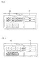
- Fig. 5 is a block diagram showing the configuration of the local cache memory 330.
- the local cache memory 330 comprises the data area 331 and a control area 332. Data read out from the storage device 800 by the host computer 200 is temporarily stored in the data area 331. A table for managing the data stored in the data area 331 is stored in the control area 332. Data is managed by providing a table having columns of "valid", “Dirty” , “Address”, “Lock”, “Owner” and “Pointer” for each data block stored in the data area 331.
- data blocks stored in the data area 331 are not limited to be in units such as unit of block, unit of cylinder or unit of track in the storage device 800.
- the size of a data block may either be a variable length or a fixed length.
- the column, "Valid" indicates whether the data in the data block is valid or not.
- the column, "Dirty" indicates whether data read out by the local cache 330 was rewritten or not by the host computer 200. If the data was rewritten, it is necessary to write the data back in the storage device 800. I f the data was not rewritten, it is not necessary to write the data back in the storage device 800.
- the column, "Address” indicates storage positions of data stored in the local cache 330.
- the host computer 200 designates data with logical addresses when it reads out data. Therefore, logical addresses are described in the column, "Address”.
- a mapping table is provided in the control area since the global cache 600 is managed with physical addresses. Data transfer between the local cache 330 and the global cache 600 is enabled by executing an exchange of logical addresses for the physical addresses referring to the mapping table.
- the column, "Lock” indicates that a process for the data stored in a pair of local caches 330 mutually therebetween is prohibited.
- Data of each of the paired local caches 330 is duplicated between them mutually at a high speed through the between-pair connection unit 350 being a communication path dedicated for data duplication but the duplication can not be achieved at the same time. Therefore, inconsistency of data occurs between the paired caches for very short time, though. If the data has been replaced from, for example, the local cache (has been written back in the global cache 600) during the occurrence of the inconsistency between the paired caches, erred data likely to be stored in the global cache 600 and the storage device 800.
- the column, "Lock” is provided in order to prevent such a problem and the operation to the data is prohibited while the Lock is effective.
- the column, "Owner” indicates which of the paired local caches 330 possesses the data.
- the column, "Owner” is provided for managing which one the data belongs to since data is stored in a duplicated manner between the paired caches mutually.
- the column, "Pointer” is a column for managing the correspondence between the data stored in the data area 331 and management information stored in the control area 332.
- Fig. 6 is a block diagram showing the configuration of the global cache 600.
- the basic configuration is same as the configuration of the global cache 330 but the meanings represented by the column, "Lock” and the column, "Owner” are different.
- the column, "Lock” indicates that the data on the global cache 600 is in a state that the data is prohibited from being read out to another local cache 330 since the data has been read out to the local cache 330 and the data is likely to be updated by the host computer 200. If a plurality of local caches 330 are allowed to read out the data, the consistency between data can not be assured since each piece of data is likely to be updated respectively by the host computer 200.
- the global cache 600 is connected to the internal connector unit 500 and two global caches 600, being paired, execute duplication of data.
- the duplication of data between the paired global caches 600 is realized by transferring each other's data mutually between them through the internal connector unit 500.
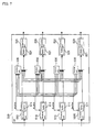
- Fig. 7 is a block diagram showing the configuration of the internal connector unit 500.
- FIG. 7 An example of a 4-input-4-output type is shown in Fig. 7 but the internal connector unit 500 according to the embodiment is an 8-input-8-output type.
- the internal connector unit 500 according to the embodiment is an 8-input-8-output type.
- 4-input-4-output type will be described for simplification of the description since their basic configurations are same.
- the internal connector unit 500 comprises a receiver unit 510, a transmitter unit 520 and a control unit 530.
- the receiver unit 510 stores data input into the internal connector unit 500 in a buffer 511 as appropriate while it transfers the data to a buffer 521 of the transmitter unit 520 specified according to an order from the control unit 530.
- the transmitter unit 520 outputs data stored in the buffer 521 one by one.
- Fig. 7 shows a case where a configuration of a cross bar switch is employed as the internal connector unit 500, the unit is not limited to the configuration of a cross bar switch and the unit can take various configurations. For example, it is possible to adapt that the receiver unit 510 and the transmitter unit 520 are connected by a multi-stage switching circuit.
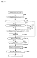
- Fig. 8 is a flowchart showing the flow of a process for the case where a data access request is issued from the host computer 200 to a disk control apparatus 100 according to this embodiment.
- Step S100 When a data access request is issued from the host computer 200 to the channel control unit 300 (Step S100), the processor 311 of the host interface control unit 310 analyzes the access request. The type of access (read-out request, write-in request), the address of the data to be accessed etc. are determined from the analysis.
- the processor 311 transmits the commands listed in Figs. 9A-9F to the cache control unit interface circuit 321 of the cache control unit 320 in response to the type of access.
- the command listed in Fig. 9D is transmitted in the case of a read-out request and the command listed in Fig. 9A and the command (data) listed in Fig. 9B are transmitted in the case of a write-in request.
- the cache control unit interface circuit 321 retrieves management information stored in the control area 332 of the local cache 330 according to a command transmitted from the processor 311 and verifies whether the data at the address specified in the command is stored in the local cache 330 (Step S101).
- the cache control unit interface circuit 321 reads out the data from the local cache 330 and transmits the data to the host computer 200. (Step S106, Step S107). Having received an acknowledgement (ACK) of the completion of the read-out process from the local cache 330, the cache control unit interface circuit 321 transmits a status to the processor 311. The status to be transmitted is a command denoted by Fig. 9F. Finally, the processor 311 sends to the host computer 200 a read-out process completion acknowledgement (Step S109) and the process is finished.
- ACK acknowledgement
- the cache control unit interface circuit 321 executes the retrieval of the management information of the control area 332 of the local cache 330, and the control such as the read-out of data from the local cache 330 is described as an example.
- the processor 311 executes such processes is also possible.
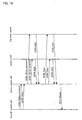
- Fig.15 is a flowchart in which the process of the above read-out request is shown. As shown in Fig. 15, two local caches 330 are paired but neither of them executes any access to each other's local cache 330 when data is being read out.
- the cache control unit interface circuit 321 writes into the local cache 330 the data stored in the buffer memory 322, transmitted from the host computer 200 (Step S108).
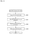
- Fig. 14 shows the details of a write-in process into the local cache 330 .
- the cache control unit interface circuit 321 issues a request to lock the local cache 330 to the other cache control unit interface circuit 321 that is paired therewith.
- This request is executed by sending a command listed in Fig. 11A through the between-pair connection unit 350.
- the cache control unit interface circuit 321 transmits the data to be written stored in the buffer memory 322, to a buffer memory 350 of the counter part through the between-pair connection unit 350.
- the write-in process is executed to the local cache 330 of the other cache control unit interface circuit 321 by the other cache control unit interface circuit 321 (Step S501).
- Step S502 the data is written in the local cache 330 by the local cache 330 itself (Step S502).
- a check is put to the column, "Dirty" in the control area 322 when the data is written in the local cache 330.
- Step S503, Step S109 A flowchart in which the above process for the write-in request is represented is shown in Fig. 16.
- a data write-in process for the other local cache 330 in a pair can be executed without being influenced by other processes by executing the process through a between-pair connection unit 350 being a dedicated communication path.
- the activity ratio of the internal connector unit 500 can be suppressed since transferring of data for duplication of data between local caches 330 is executed without using the internal connector unit 500. Therefore, contention of data in the internal connector unit 500 can be alleviated and data access responses to a host computer 200 can be sent at a high speed.
- Step S102 whether the requested data is present in the global cache 600 is verified.
- a cache control unit interface circuit 321 obtains a physical address referring to the mapping table in the control area 332 based on the logical address of the data specified in a command transmitted from the processor 311. Then, the cache control unit interface circuit 321 transmits the command to the global cache 600 through the internal connection unit 500 and retrieves the management information stored in the control area 602 of the global cache 600 and verifies whether the data is stored in the global cache 600.
- the cache control unit interface circuit 321 transmits the command to the disk control unit 400, reads out the data from a storage device 800 and causes the global cache 600 to store the data (Step S103).
- the data stored in the global cache 600 is also sent to the other global cache 600 through the internal connector unit 500 and the data is duplicated.
- the aspect it is possible for the aspect to be adapted such that the process for transferring as soon as possible to the host computer the data read out from the storage device 800 to the global cache 600 is caused to precede the duplication of the data on the global cache 600. Since the data on the global cache 600 is also stored in the storage device 800, there will be no problem if the data is lost on the global cache 600. The reliability of the data can be secured by executing the duplication when the data is updated.
- Step S104 the data is locked on the global cache 600 (Step S104). That is, the data on the global cache 600 is caused to prevent from being read out from another local cache 330.
- the flow of the above process is shown in the flowchart in Fig. 10.
- Step S200 In the case where the data has been already read out by another local cache 330 and is locked (Step S200), the local cache 330 is requested to release the lock (Step S201). Which local cache 330 has locked can be known from the column, "Owner" of the control area 602.
- Step S202 After waiting for the lock to be released (Step S202), the data is locked not to be read out from another local cache 330 and the process is finished (Step S203). If the other local cache 330 is not locked, it is locked at once and the process is finished (Step S200, Step S203).
- Step S105 a process in which the data stored in the global cache 600 is read out to a local cache 330.
- the flow of the process is shown in the flowchart in Fig. 12.
- Step S300 whether an empty area for writing the data in is present on the local cache 330 is checked. This process can be executed by checking whether the total amount of the invalid data is larger than the amount of the data transferred from the global cache 600 by retrieving the column, "Valid" of the control area 332.
- the cache control unit interface circuit 321 secures locking by sending to the other cache control unit interface circuit 321 in the pair a request to lock the local cache 330 (Step S302).
- the cache control unit interface circuit 321 stores the data from the global cache 600 to the buffer memory 322, and transmits the data to the other buffer memory 350 in the pair through the between-pair connection unit 350 and simultaneously writes the data into its own local cache 330 (Step S303, Step S304).
- the lock is caused to be released and the process is finished (Step S305). The processes following this are executed as described above in response to an access request from the host computer 200 (Step S106 to S109).
- Step S301 a process is necessary in which an empty area is secured by writing any piece of data on the local cache 330 back into the global cache 600 (Step S301 ) .
- the flow of the process is shown in the flowchart in Fig. 13.
- the cache control unit interface circuit 321 secures locking by sending to the other cache control unit interface circuit 321 in the pair a request to lock the local cache 330 (Step S400).
- the cache control unit interface circuit 321 checks using the control area 332 a Dirty bit of the data written out to the global cache 600 identified according to a predetermined algorithm (Step S401).
- a predetermined algorithm the Least Recently Used (LRU) scheme in which the data that has not been accessed for the longest time is written out from the cache is common but another algorithm may be used.
- LRU Least Recently Used
- Step S402 it is not necessary to write out the data to the global cache 600 if a Dirty bit is not set. However, since it is necessary to write out the data to the global cache 600 if the Dirty bit is set, whether there is any empty area to write in the data in the global cache 600 is checked (Step S402). If there is no enough empty area in the global cache 600, an area is secured by writing some data stored in the global cache 600 out to the storage device 800 (Step S403).
- Step S404 the data is written in the emptied area on the global cache 600 from the local cache 330 (Step S404).
- the write-out process is executed to two (2) global caches 600.
- the data is not "dirty" any more and the Dirty bit is reset (Step S405).
- Step S406 the valid bit of the data is reset (Step S407).
- Step S408 an acknowledgement notifying that the read-out process of the data to the global cache 600 has been completed is sent to the other local cache 330 in the pair.
- the valid bit in the control area 332 is reset.
- the lock of the local cache 330 is released (Step S409) and the process is finished.
- the processor 311 in the host interface control unit 310 always monitors whether there is any abnormality in the channel control unit 300 (Step S800). when the processor 311 detects any abnormality in the channel control unit 300, it does not use the local cache 330 any more and makes the local cache 330 invalid (Step S801). Then, data already stored in the local cache 330 is written out on the global cache 600 (Step S802).
- the data written out in this case is the data for which the Dirty bit is set.
- the lock of the data written out from the local cache 330 is released on the global cache 600 (Step S803). This is for enabling the data to be read out to another local cache 330.
- the operation of the system stops and waits for the channel control unit 300 to recover to be normal (Step S804).
- the data accesses from the host computer 200 during this waiting are continued by the other channel control unit 300 paired with the channel control unit 300.
- the local cache 330 is made valid and its use is resumed (Step S805).
- the work can be continued without stopping the operation of the system by using the other channel control unit 300 in the pair even when a fault occurs to the channel control unit 300.
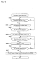
- Fig. 18 is a flowchart showing an emergency de staging process in the storage control apparatus 100 according to this embodiment.
- the emergency destaging process is a technique for protecting the data stored in cache memories when the supply of power to the disk control apparatuses 100 is stopped due to a sudden power-down etc. Power is supplied from the battery 700 during a power-down. However, since the power consumption of the disk control apparatus 100 is not little, the supply of power from the battery 700 can not be maintained for a long time. Therefore, the emergency destaging process is required to be completed in a brief period of time as far as possible.
- the disk control apparatuses 100 start the emergency destaging process when they detect that the supply of power is switched to the supply of power from the battery. First, the disk control apparatuses 100 research whether there is some data, among the data stored in the local cache 330, that is not yet reflected to the global cache 600, by retrieving Dirty bits in the control area 332 (Step S900).
- Step S901 The data not yet reflected to the global cache 600 is written out to two (2) global caches 600 (Step S901).
- Step S903 the power source of the channel control unit 300 is blocked (Step S903). This is for reducing the power consumption as little as possible and for maintaining the power supply by the battery 700 as long as possible.
- the disk control apparatuses 100 research whether there is some data, among the data stored in the global cache 600, that is not yet reflected to the storage device 800, by retrieving Dirty bits in the control area 602 (Step S904).
- the data not yet reflected to the storage device 800 is written out to the storage device 800 through the disk control unit 400 (Step S905).
- Step S906 the power sources of the global cache 600, the disk control unit 400 and the storage device 800 are blocked (Step S907) and the process is finished.
- Step S903 an aspect in which the supply of power to the entire channel control unit 300 is blocked in Step S903 but also an aspect in which the supply of power to a portion of the channel control unit 300 is blocked and the supply of power to the channel control unit 300 is reduced may be employed.
- an aspect in which the total supply of power is reduced by blocking the supply of power to the processor 311, the part consuming relatively large power among the channel control unit 300, may be employed.
- each host computer 200 can access cache memories without competing with data accesses from other host computers 200 and high speed data accesses can be realized since the local caches 330 are deployed in a distributed manner in each channel control unit 300.
- the overhead of the duplication process of data can be reduced since the local caches being paired for the duplication of data are connected by a dedicated between-pair connection unit 350 and, therefore, further higher speed for data accesses from the host computers 200 can be realized.
- the activity ratio of the internal connector unit 500 can be suppressed since data transfer for the duplication of data between the local caches 330 is executed without using the internal connector unit 500. Therefore, data competition in the internal connector unit 500 is reduced and data access responses to the host computers 200 can be executed at a higher speed.
- the storage device 800 it is not necessary to access the storage device 800 to read out data to be accessed from a host computer 200 when the data is stored in the global cache 600 even if the data is not stored in the local cache 330. Therefore, the access speed from the host computers 200 can be made higher.
- an aspect in which the between-pair connection unit 350 is not provided can be considered. Even in such an aspect, duplication of data can be executed at a higher speed by carrying out the communication between paired two (2) local caches 330 at a higher rate.
- the communication between the two local caches 330 is carried out through the internal connector unit 500.
- data transfers between the paired components can be carried out at a higher speed without being influenced by other data transfers, and is same as shown in disk control apparatus 100 in the first embodiment.
- fig. 19 is a block diagram showing the entire configuration of a computer system according to a third example.
- a control memory 100 is provided to the internal connector unit 500 in order to manage data read out to a certain local cache 330, not to be read out to another local cache 330.
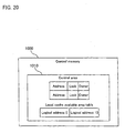
- a control memory 1000 The configuration of a control memory 1000 is shown in Fig. 20.
- the control memory 1000 has a control area 1010 for managing data already read out to the local cache 330.
- the control area 1010 comprises columns, "Address”, “Lock” and "Owner”.
- the column, "Address” indicates physical address information of the data already read out to the local cache 330.
- the column, “Lock” indicates a state where reading out of the data already read out to the local cache 330, to other local caches 330 is prohibited since the data specified in the column, "Address” has been already read out to the local cache 330 and may be updated by the host computer 200. This is because, if reading out of the data to a plurality of local caches 330 is allowed, each of those read out pieces of data may be updated respectively and independently and the consistency of data can not be assured.
- the column, "Owner” indicates a local cache 330 being reading out the data.
- the additional configuration for the disk control apparatus 100 according to the third example is same as that of the disk control apparatus 100 according to the first example.
- Fig. 21 shows a flowchart showing the flow of the process for the case where a data access request is issued to the disk control apparatus 100 from a host computer 200 according to this example.
- the processor 311 of the host interface control unit 310 analyzes the access request.
- the type of access read-out request, write-in request), the address of the data to be accessed etc. are determined from the analysis.
- the processor 311 transmits a command listed in Fig. 9 to the cache control unit interface circuit 321 of the cache control unit 320 in response to the type of the access.
- the command listed in (d) in Fig. 9 is transmitted for the case of a read-out request and the command listed in (a) and the command (data) listed in (b) in Fig. 9 are transmitted for the case of a write-in request.
- the cache control unit interface circuit 321 retrieves the management information stored in the control area 332 of the local cache 330 according to the command transmitted from the processor 311 and verifies whether the data at the address specified in the command is stored in the local cache 330 (Step S1001).
- the cache control unit interface circuit 321 reads out the data from the local cache 330 and transmits the data to the host computer 200 (Step S1004, Step S1005). Having received an acknowledgement (ACK) of the completion of the read-out process from the local cache 330, the cache control unit interface circuit 321 transmits a status to the processor 311. The status to be transmitted is a command denoted by (f) in Fig. 9. Finally, the processor 311 sends to the host computer 200 a read-out process completion acknowledgement (Step S1007) and the process is finished.
- ACK acknowledgement
- the cache control unit interface circuit 321 writes into the local cache 330 the data stored in the buffer memory 322 having been transmitted from the host computer 200 (Step S1006).
- the cache control unit interface circuit 321 sends a request to the other cache control unit interface circuit 321 in the pair to lock the local cache 330 .
- This request is executed by transmitting the command listed in (a) in Fig. 11 through the between-pair connection unit 350 .
- the cache control unit interface circuit 321 Having received from the counter part a response (the command listed in (b) in Fig. 11) indicating that the lock has been secured and, having secured the lock of both local caches 330 in the pair (Step S1400), the cache control unit interface circuit 321 transmits the data stored in the buffer memory 322 to the buffer memory 350 of the counter part through the between-pair connection unit 350.
- Step S1401 a write-in process is executed to the local cache 330 of the counter part by the cache control unit interface circuit 321 of the counter part. Then, a write-in process is executed to the local cache 330 itself (Step S1402). when the data is written in the local cache 330, a check is put to the column, "Dirty" of the control area 322 .
- Step S1403, Step S1007 an acknowledgement of completion is transmitted to the host computer 200 and the process is finished.
- write-in processes of data to the other local cache 330 in the pair can be executed at a high speed without being influenced by other processes by executing the write-in processes through the between-pair connection unit 350 being a dedicated communication path.
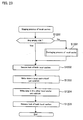
- Step S1002 a process for reading out to the local cache 330 the data stored in a storage device 800 is executed. The flow of the process is shown in Fig. 23.
- Step S1200 First, before the data is transferred from the storage device 800 to the local cache 330, whether an empty area for writing the data in is present on the local cache 330 is checked (Step S1200). This process can be executed by checking whether the total amount of the invalid data is larger than the amount of the data transferred from the storage device 800 by retrieving the column, "Valid" of the control area 332.
- the cache control unit interface circuit 321 secures locking by sending to the other cache control unit interface circuit 321 in the pair a request to lock the local cache 330 (Step S1202).
- the cache control unit interface circuit 321 stores the data from the storage device 800 to the buffer memory 322, and transmits the data to the other buffer memory 350 in the pair through the between-pair connection unit 350 and simultaneously writes the data into its own local cache 330 (Step S1203, Step S1204).
- the lock is caused to be released and the process is finished (Step S1205).
- the processes following this are executed as described above in response to access requests from the host computer 200 (Step S1004 to Step S1007).
- Step S1201 If there is no empty area for the data to be transferred from the storage device 800 to the local cache 330, a process is necessary in which an empty area is secured by writing any piece of data on the local cache 330 back in the storage device 800 (Step S1201). The flow of the process is shown in the flowchart in Fig. 24.
- the cache control unit interface circuit 321 secures locking by sending to the other cache control unit interface circuit 321 in the pair a request to lock the local cache 330 (Step S1300).
- the cache control unit interface circuit 321 checks using the control area 332 a Dirty bit of the data written out to the storage device 800 identified according to a predetermined algorithm (Step S1301).
- a predetermined algorithm LRU scheme in which the data that has not been accessed for the longest time is written out from the cache is common but another algorithm may be used.
- Step 1302 It is not necessary to write out the data to the storage device 800 if a Dirty bit is not set.
- the data is written out from the local cache 330 to the storage device 800 if the Dirty bit is set (Step 1302).
- the writing-out process is executed through a disk control unit 400.
- the data is not "dirty” any more and the Dirty bit is reset (Step S1303).
- the Valid bit of the data is reset (Step S1305).
- Step S1306 an acknowledgement notifying that the read-out process of the data to the storage device 800 has been completed is sent to the other local cache 330 in the pair.
- the Valid bit in the control area 332 is reset.
- the lock of the local cache 330 is released (Step S1307) and the process is finished.
- Step S1003 the data read out to the local cache 330 is locked in the control memory 1000. That is, the data read out to the local cache 330 is prevented from being read out by another local cache 330.
- the flow of the process is shown in the flowchart in Fig. 22.
- Step S1101 In the case where the data has been already read out to another local cache 330 and is locked (Step S1100), the local cache 330 is requested to release the lock (Step S1101). Which local cache 330 has locked can be known from the column, "Owner" of the control area 1010. After waiting for the lock to be released (Step S1102), the data is locked not to be read out from another local cache 330 and the process is finished (Step S1103). If the other local cache 330 is not locked, it is locked at once and the process is finished (Step S1100, Step S1103).
- the reliability of the data is improved since the data to be stored in the local cache 330 is duplicated.
- each host computer 200 can access cache memories without competing with data accesses requests from other host computers 200 and high speed data accesses can be realized since the local caches 330 are deployed in a distributed manner to each channel control unit 300.
- the overhead of the duplication process of data can be reduced since the local caches being paired for the duplication of data are connected by a dedicated between-pair connection unit 350 and, therefore, further a higher speed for data accesses from the host computers 200 is realized.
- the activity ratio of the internal connector unit 500 can be suppressed since data transfer for the duplication of data between the local caches 330 is executed without using the internal connector unit 500. Therefore, data competition in the internal connector unit 500 can be reduced and data access responses to the host computers 200 can be executed at a higher speed.
- the access speed for data stored in cache memories of the storage control apparatuses can be made higher.
Abstract
Description
cutting off the supply of power from the battery to the storage control apparatus after completion of the writing to the storage device.
Claims (22)
- A storage control apparatus including a plurality of channel control units (300) each having an interface with an information processor (200); a disk control unit (400) having an interface with a storage device (800) for storing data; and a cache memory (330) for storing temporarily data to be interchanged between the information processor and the storage device,
the storage control apparatus comprising an internal connector unit (500) for connecting mutually the plurality of channel control units and the disk control unit,
wherein the cache memory (330) is disposed in each of the plurality of channel control units (300) that are connected to one another through a dedicated data transfer path (350) used for storing mutually the data stored in the cache memories (330). - A storage control apparatus including a channel control unit (300) having an interface with an information processor (200); a disk control unit (400) having an interface with a storage device (800) for storing data; and first and second cache memories (330, 600) for storing temporarily data to be interchanged between the information processor and the storage device,
the storage control apparatus comprising an internal connector unit (500) for connecting the channel control unit and the disk control unit to each other,
wherein the first cache memory (330) is disposed in the channel control unit (300), and the second cache memory (600) is disposed in the internal connector unit (500). - A storage control apparatus including a plurality of channel control units (300) each having an interface with an information processor (200); a disk control unit (400) having an interface with a storage device (800) for storing data; and first and second cache memories (330, 600) for storing temporarily data to be interchanged between the information processor and the storage device,
the storage control apparatus comprising an internal connector unit (500) for connecting mutually the plurality of channel control units and the disk control unit,
wherein the first cache memory (330) is disposed in each of the plurality of channel control units (300) that are connected to one another through a dedicated data transfer path (350) used for storing mutually the data stored in the first cache memories (330), and a couple of the second cache memories (600) for storing mutually the same data are connected to the internal connector unit (500). - A storage system comprising the storage control apparatus (100) and the storage device (800) according to claim 1.
- A method for writing data to a cache memory by a channel control unit (300) for the case where a data write-in request is issued from an information processor (200) to a storage control apparatus (100), the storage control apparatus including a plurality of the channel control units each having an interface with the information processor; a disk control unit (400) having an interface with a storage device (800) for storing data; the cache memory (330) for storing temporarily data to be interchanged between the information processor and the storage device, the cache memory (330) being disposed in each of the plurality of channel control units (300) that are connected to one another through a dedicated data transfer path (350) used for storing mutually the data temporarily stored; and an internal connector unit (500) for connecting mutually the plurality of channel control units and the disk control unit, comprising:receiving data to be written from the information processor;writing the data to be written to the cache memory;transmitting the data to be written through the dedicated data transfer path to the other channel control unit connected to each other through the dedicated data transfer path,receiving through the dedicated data transfer path an acknowledgement notifying that writing of the transmitted data to the cache memory disposed in the other channel control unit has been completed, from the other channel control unit; andtransmitting the acknowledgement notifying that writing to the cache memory of the data to be written has been completed, to the information processor.
- A method for reading in data stored in a second cache memory (600) to a first cache memory (330) by a channel control unit (300) in a storage control apparatus (100), the storage control apparatus including a plurality of the channel control units (300) each having an interface with an information processor (200); a disk control unit (400) having an interface with a storage device (800) for storing data; the first cache memory (330) for storing temporarily data to be interchanged between the information processor and the storage device, the first cache memory (330) being disposed in each of the plurality of channel control units (300) that are connected to one another through a dedicated data transfer path (350) used for storing mutually the data temporarily stored; a couple of the second cache memories (600) for storing the same data mutually; and an internal connector unit (500) for connecting mutually the plurality of channel control units, the disk control unit and the couple of second cache memories, comprising:transmitting a read-in command of the data to the second cache memory;acquiring the data from the second cache memory;writing the acquired data to the first cache memory;transmitting the acquired data through the dedicated data transfer path to the other channel control unit connected to each other through the dedicated data transfer path; andreceiving an acknowledgement notifying that the writing of the transmitted data to the cache memory disposed in the other channel control unit has been completed, from the other channel control unit.
- A method for reading out data by a channel control unit (300) for the case where a data read-out request is issued from an information processor (200) to a storage control apparatus (100), the storage control apparatus including a plurality of the channel control units (300) each having an interface with the information processor; a disk control unit (400) having an interface with a storage device (800) for storing data; a first cache memory (330) for storing temporarily data to be interchanged between the information processor and the storage device, the first cache memory (330) being disposed in each of the plurality of channel control units (300) connected to one another through a dedicated data transfer path (350) used for storing mutually the data temporarily stored; a couple of second cache memories (600) for storing the same data mutually; and an internal connector unit (500) for connecting mutually the plurality of channel control units, the disk control unit and the couple of second cache memories, comprising:receiving from the information processor a read-out command for data for which the address is specified;determining whether the data at the specified address is stored in the first cache memory;transmitting a read-in command of the data to the second cache memory if the data at the specified address is not stored in the first cache memory;acquiring the data from the second cache memory;writing the acquired data to the first cache memory;transmitting the acquired data through the dedicated data transfer path to the other channel control unit connected to each other through the dedicated data transfer path;receiving from the other channel control unit an acknowledgement notifying that writing of the transmitted data to the cache memory disposed in the other channel control unit has been completed; andtransmitting the data to the information processor.
- A method for writing out data stored in a first cache memory (330) to a second cache memory (600) by a channel control unit (300) in a storage control apparatus (100), the storage control apparatus including a plurality of the channel control units (300) each having an interface with an information processor (200); a disk control unit (400) having an interface with a storage device (800) for storing data; the first cache memory (330) for storing temporarily data to be interchanged between the information processor and the storage device, the first cache memory (330) being disposed in each of the plurality of channel control units (300) connected to one another through a dedicated data transfer path (350) used for storing mutually the data temporarily stored; a couple of the second cache memories (600) for storing the same data mutually; and an internal connector unit (500) for connecting mutually the plurality of channel control units, the disk control unit and the couple of second cache memories, comprising:selecting the data to be written out to the second cache memory among the data stored in the first cache memory;securing a storage area to write in the selected data to the second cache memory; andtransmitting the selected data to the second cache memory.
- A method for writing out data according to claim 8, wherein the selection is carried out by selecting data that has not been accessed for the longest period of time.
- A method for storing by a storage control apparatus (100) into a storage device (800) data stored in a first cache memory (330) and in a second cache memory (600) for the case where power supply to the storage control apparatus (100) is interrupted, the storage control apparatus including a plurality of channel control units (300) each having an interface with an information processor (200); a disk control unit (400) having an interface with the storage device (800) for storing data; the first cache memory (330) for storing temporarily data to be interchanged between the information processor and the storage device, the first cache memory (330) being disposed in each of the plurality of channel control units (300) connected to one another through a dedicated data transfer path (350) used for storing mutually the data temporarily stored; a couple of the second cache memories (600) for storing the same data mutually; and an internal connector unit (500) for connecting mutually the plurality of channel control units, the disk control unit and the couple of second cache memories, comprising:switching the power source to a battery provided in advance in the storage control apparatus;writing to the second cache memory data stored in the first cache memory that has been updated by the information processor and that has not yet been written into the second cache memory;reducing the amount of power supplied from the battery to the channel control unit after completion of the writing to the second cache memory;writing to the storage device data stored in the second cache memory that has been updated by the information processor and that has not yet been written in to the storage device; andcutting off the supply of power from the battery to the storage control apparatus after completion of the writing to the storage device.
- A channel control unit in a storage control apparatus (100) including a plurality of the channel control units (300) each having an interface with an information processor (200); a disk control unit (400) having an interface with a storage device (800) for storing data; and a cache memory (330) for storing temporarily data to be interchanged between the information processor and the storage device, the channel control unit (300) comprising:an internal connector unit (500) for connecting mutually the cache memory, the plurality of channel control units and the disk control unit, the cache memory (330) being disposed in each of the plurality of channel control units (300) connected to one another through a dedicated data transfer path (350) used for storing mutually the stored data;a receiver (310, 314) for receiving data to be written from the information processor;a writing portion (320, 321) for writing the data to be written to the cache memory;a transmitter (320, 325) for transmitting the data to be written through the dedicated data transfer path (350) to the other channel control unit connected to each other through the dedicated data transfer path;a receiver (320, 325) for receiving from the other channel control unit through the dedicated data transfer path (350) an acknowledgement notifying that the writing of the transmitted data to the cache memory disposed in the other channel control unit has been completed; anda transmitter (310, 314) for transmitting to the information processor the acknowledgement notifying that the writing to the cache memory of the data to be written has been completed.
- A channel control unit in a storage control apparatus (100) including a plurality of the channel control units (300) each having an interface with an information processor (200); a disk control unit (400) having an interface with a storage device (800) for storing data, a first cache memory (330) for storing temporarily data to be interchanged between the information processor and the storage device, the first cache memory (330) being disposed in each of the plurality of channel control units (300) connected to one another by a dedicated data transfer path (350) used for storing mutually the data temporarily stored; a couple of second cache memories (600) for storing the same data mutually; and an internal connector unit (500) for connecting mutually the plurality of channel control units, the disk control unit and the couple of second cache memories, the channel control unit (300) comprising:a transmitter (340) for transmitting to the second cache memory (600) a read-in command for data stored in the second cache memory;an acquiring portion (340) for acquiring the data from the second cache memory;a writing portion (320, 321) for writing the acquired data to the first cache memory (330);a transmitter (320, 325) for transmitting the acquired data through the dedicated data transfer path (350) to the other channel control unit (300) connected to each other through the dedicated data transfer path (350); anda receiver (320, 325) for receiving from the other channel control unit (300) an acknowledgement notifying that the writing of the transmitted data to the cache memory (330) disposed in the other channel control unit has been completed.
- A channel control unit in a storage control apparatus (100) including a plurality of the channel control units (300) each having an interface with an information processor (200); a disk control unit (400) having an interface with a storage device (800) for storing data; a first cache memory (330) for storing temporarily data to be interchanged between the information processor and the storage device, the first cache memory (330) being disposed in each of the plurality of channel control units (300) connected to one another through a dedicated data transfer path (350) used for storing mutually the data temporarily stored; a couple of second cache memories (600) for storing the same data mutually; and an internal connector unit (500) for connecting mutually the plurality of channel control units, the disk control unit and the couple of second cache memories, the channel control unit comprising:a receiver (310, 314) for receiving from the information processor a read-out command for data for which the address is specified;a determining portion (320, 332) for determining whether the data at the specified address is stored in the first cache memory (330);a transmitter (340) for transmitting the read-in command for the data to the second cache memory (600) if the data at the specified address is not stored in the first cache memory;an acquiring portion (340) for acquiring the data from the second cache memory;a writing portion (320, 321) for writing the acquired data to the first cache memory (330);a transmitter (320, 325) for transmitting the acquired data through the dedicated data transfer path (350) to the other channel control unit (300) connected to each other through the dedicated data transfer path;a receiver (320, 325) for receiving from the other channel control unit (300) an acknowledgement notifying that the writing of the transmitted data to the cache memory (330) disposed in the other channel control unit has been completed; anda transmitter (310, 314) for transmitting the data to the information processor.
- A channel control unit in a storage control apparatus (100) including a plurality of the channel control units (300) each having an interface with an information processor (200); a disk control unit (400) having an interface with a storage device (800) for storing data; a first cache memory (330) for storing temporarily data to be interchanged between the information processor and the storage device, the first cache memory (330) being disposed in each of the plurality of channel control units (300) connected to one another through a dedicated data transfer path (350) used for storing mutually the data temporarily stored; a couple of second cache memories (600) for storing the same data mutually; and an internal connector unit (500) for connecting mutually the plurality of channel control units, the disk control unit and the couple of second cache memories, the channel control unit (300) comprising:a selector for selecting the data to be written out to the second cache memory (600) among data stored in the first cache memory;a securing portion for securing a storage area to write in the selected data to the second cache memory; anda transmitter (340) for transmitting the selected data to the second cache memory.
- A channel control unit according to claim 14, wherein the selection is carried out by selecting the data that has not been accessed for the longest period of time.
- A storage control apparatus including a plurality of channel control units (300) each having an interface with an information processor (200); a disk control unit (400) having an interface with a storage device (800) for storing data; a first cache memory (330) for storing temporarily data to be interchanged between the information processor and the storage device, the first cache memory (330) being disposed in each of the plurality of channel control units (300) connected to one another through a dedicated data transfer path (350) used for storing mutually the data temporarily stored; a couple of second cache memories (600) for storing the same data mutually; and an internal connector unit (500) for connecting mutually the plurality of channel control units, the disk control unit and the second cache memories, the storage control apparatus comprising:a battery (700) for continuously supplying power when supply of power to the storage control apparatus is interrupted;a switch for switching the power source to the battery when supply of power to the storage control apparatus is interrupted;a writing portion for writing to the second cache memory (600) data stored in the first cache memory (330) that has been updated by the information processor and that has not yet been written in to the second cache memory;a reducing portion for reducing the supply of power from the battery (700) to the channel control unit (300) after completion of writing to the second cache memory;a writing portion for writing to the storage device (800) data stored in the second cache memory (600) that has been updated by the information processor and that has not yet been written in to the storage device; anda cutoff portion for cutting off the supply of power from the battery to the storage control apparatus (100) after completion of the writing to the storage device.
- A computer-readable medium containing a computer program executed on a channel control unit (300) in a storage control apparatus (100) including a plurality of the channel control units (300) each having an interface with the information processor (200); a disk control unit (400) having an interface with a storage device (800) for storing data; a cache memory (330) for storing temporarily data to be interchanged between the information processor and the storage device, the cache memory (330) being disposed in each of the plurality of channel control units (300) connected to one another through a dedicated data transfer path (350) used for storing mutually the data temporarily stored; and an internal connector unit (500) for connecting mutually the plurality of channel control units and the disk control unit, comprising:receiving data to be written from the information processor;writing the data to be written to the cache memory;transmitting the data to be written through the dedicated data transfer path to the other channel control unit connected to each other through the dedicated data transfer path;receiving from the other channel control unit through the dedicated data transfer path an acknowledgement notifying that the writing of the transmitted data to the cache memory disposed in the other channel control unit has been completed; andtransmitting to the information processor an acknowledgement notifying that the writing to the cache memory of the data to be written has been completed.
- A computer-readable medium containing a computer program executed on a channel control unit (300) in a storage control apparatus (100) including a plurality of the channel control units (300) each having an interface with an information processor (200); a disk control unit (400) having an interface with a storage device for storing data; a first cache memory (330) for storing temporarily data to be interchanged between the information processor and the storage device, the first cache memory (330) being disposed in each of the plurality of channel control units (300) connected to one another through a dedicated data transfer path (350) used for storing mutually the data temporarily stored; a couple of second cache memories (600) for storing the same data mutually; and an internal connector unit (500) for connecting mutually the plurality of channel control units, the disk control unit and the couple of second cache memories, comprising:transmitting to the second cache memory a read-in command for data stored in the second cache memory;acquiring the data from the second cache memory;writing the acquired data to the first cache memory;transmitting the acquired data through the dedicated data transfer path to the other channel control unit connected to each other through the dedicated data transfer path; andreceiving from the other channel control unit an acknowledgement notifying that the writing of the transmitted data to the cache memory disposed in the other channel control unit has been completed.
- A computer-readable medium containing a computer program executed on a channel control unit (300) in a storage control apparatus (100) including a plurality of channel control units (300) each having an interface with an information processor (200), a disk control unit (400) having an interface with a storage device (800) for storing data; a first cache memory (330) for storing temporarily data to be interchanged between the information processor and the storage device, the first cache memory (330) being disposed in each of the plurality of channel control units (300) connected to one another through a dedicated data transfer path (350) used for storing mutually the data temporarily stored; a couple of second cache memories (600) for storing the same data mutually; and an internal connector unit (500) for connecting mutually the plurality of channel control units, the disk control unit and the couple of second cache memories, comprising:receiving from the information processor a read-out command for data for which the address is specified;determining whether the data at the specified address is stored in the first cache memory;transmitting a read-in command for the data at the specified address to the first cache memory if the data is not stored in the first cache memory;acquiring the data from the second cache memory;writing the acquired data to the first cache memory;transmitting the acquired data through the dedicated data transfer path to the other channel control unit connected to each other through the dedicated data transfer path;receiving from the other channel control unit an acknowledgement notifying that the writing of the transmitted data to the cache memory disposed in the other channel control unit has been completed; andtransmitting the data to the information processor.
- A computer-readable medium containing a computer program executed on a channel control unit (300) in a storage control apparatus (100) including a plurality of channel control units (300) each having an interface with an information processor (200), a disk control unit (400) having an interface with a storage device (800) for storing data; a first cache memory (330) for storing temporarily data to be interchanged between the information processor and the storage device, the first cache memory (330) being disposed in each of the plurality of channel control units (300) connected to one another through a dedicated data transfer path (350) used for storing mutually the data temporarily stored; a couple of second cache memories (600) for storing the same data mutually; and an internal connector unit (500) for connecting mutually the plurality of channel control units, the disk control unit and the couple of second cache memories, comprising:selecting data to be written out to the second cache memory among data stored in the first cache memory;securing a storage area to write the selected data to the second cache memory; andtransmitting the selected data to the second cache memory.
- A computer-readable medium containing a computer program according to claim 20, wherein the selection is carried out by selecting the data that has not been accessed for the longest period of time.
- A computer-readable medium containing a computer program executed in a storage control apparatus (100) including a plurality of channel control units (300) each having an interface with an information processor (200); a disk control unit (400) having an interface with a storage device (800) for storing data; a first cache memory (330) for storing temporarily data to be interchanged between the information processor and the storage device, the first cache memory (330) being disposed in each of the plurality of channel control units (300) connected to one another through a dedicated data transfer path (350) used for storing mutually the data temporarily stored; a couple of second cache memories (600) for storing the same data mutually; and an internal connector unit (500) for connecting mutually the plurality of channel control units, the disk control unit and the couple of second cache memories, comprising:switching the power source to a battery for continuously supplying power to the storage control apparatus when the supply of power to the storage control apparatus is interrupted;writing to the second cache memory data stored in the first cache memory that has been updated by the information processor and that has not yet been written into the second cache memory;reducing the amount of power supplied from the battery to the channel control unit after completion of the writing to the second cache memory;writing to the storage device data stored in the second cache memory that has been updated by the information processor and that has not yet been written into the storage device; andcutting off the supply of power from the battery to the storage control apparatus after completion of the writing to the storage device.
Applications Claiming Priority (2)
| Application Number | Priority Date | Filing Date | Title |
|---|---|---|---|
| JP2002273162 | 2002-09-19 | ||
| JP2002273162A JP2004110503A (en) | 2002-09-19 | 2002-09-19 | Memory control device, memory system, control method for memory control device, channel control part and program |
Publications (2)
| Publication Number | Publication Date |
|---|---|
| EP1400894A2 true EP1400894A2 (en) | 2004-03-24 |
| EP1400894A3 EP1400894A3 (en) | 2005-07-06 |
Family
ID=31944575
Family Applications (1)
| Application Number | Title | Priority Date | Filing Date |
|---|---|---|---|
| EP03021100A Withdrawn EP1400894A3 (en) | 2002-09-19 | 2003-09-18 | Storage controller |
Country Status (3)
| Country | Link |
|---|---|
| US (1) | US7380058B2 (en) |
| EP (1) | EP1400894A3 (en) |
| JP (1) | JP2004110503A (en) |
Cited By (3)
| Publication number | Priority date | Publication date | Assignee | Title |
|---|---|---|---|---|
| EP1708076A1 (en) * | 2005-04-01 | 2006-10-04 | Hitachi, Ltd. | Storage system and storage control method |
| WO2009131560A1 (en) | 2008-04-22 | 2009-10-29 | Lsi Corporation | Distributed cache system in a drive array |
| US8549226B2 (en) | 2004-05-14 | 2013-10-01 | Hewlett-Packard Development Company, L.P. | Providing an alternative caching scheme at the storage area network level |
Families Citing this family (21)
| Publication number | Priority date | Publication date | Assignee | Title |
|---|---|---|---|---|
| JP4190859B2 (en) * | 2002-10-28 | 2008-12-03 | 株式会社日立製作所 | Storage device control device and storage device control device control method |
| JP4401788B2 (en) * | 2004-01-06 | 2010-01-20 | 株式会社日立製作所 | Storage controller |
| JP2005217815A (en) * | 2004-01-30 | 2005-08-11 | Hitachi Ltd | Path control method |
| JP4441286B2 (en) * | 2004-02-10 | 2010-03-31 | 株式会社日立製作所 | Storage system |
| JP4405277B2 (en) * | 2004-02-16 | 2010-01-27 | 株式会社日立製作所 | Disk controller |
| US7467238B2 (en) * | 2004-02-10 | 2008-12-16 | Hitachi, Ltd. | Disk controller and storage system |
| JP4477906B2 (en) * | 2004-03-12 | 2010-06-09 | 株式会社日立製作所 | Storage system |
| JP2005293478A (en) | 2004-04-05 | 2005-10-20 | Hitachi Ltd | Storage control system, channel controller equipped with the same system and data transferring device |
| US7519796B1 (en) | 2004-06-30 | 2009-04-14 | Sun Microsystems, Inc. | Efficient utilization of a store buffer using counters |
| US7290116B1 (en) | 2004-06-30 | 2007-10-30 | Sun Microsystems, Inc. | Level 2 cache index hashing to avoid hot spots |
| US7366829B1 (en) | 2004-06-30 | 2008-04-29 | Sun Microsystems, Inc. | TLB tag parity checking without CAM read |
| US7543132B1 (en) | 2004-06-30 | 2009-06-02 | Sun Microsystems, Inc. | Optimizing hardware TLB reload performance in a highly-threaded processor with multiple page sizes |
| US7571284B1 (en) | 2004-06-30 | 2009-08-04 | Sun Microsystems, Inc. | Out-of-order memory transactions in a fine-grain multithreaded/multi-core processor |
| US7620773B2 (en) * | 2005-04-15 | 2009-11-17 | Microsoft Corporation | In-line non volatile memory disk read cache and write buffer |
| US7606807B1 (en) * | 2006-02-14 | 2009-10-20 | Network Appliance, Inc. | Method and apparatus to utilize free cache in a storage system |
| JP2008097527A (en) | 2006-10-16 | 2008-04-24 | Hitachi Ltd | Storage system and control method thereof |
| US8850114B2 (en) | 2010-09-07 | 2014-09-30 | Daniel L Rosenband | Storage array controller for flash-based storage devices |
| US9280497B2 (en) | 2012-12-21 | 2016-03-08 | Dell Products Lp | Systems and methods for support of non-volatile memory on a DDR memory channel |
| JP5907105B2 (en) * | 2013-03-26 | 2016-04-20 | 日本電気株式会社 | Storage device, method, and program. |
| US9355034B2 (en) * | 2013-12-31 | 2016-05-31 | Samsung Electronics Co., Ltd. | Removal and optimization of coherence acknowledgement responses in an interconnect |
| KR101619623B1 (en) * | 2014-10-20 | 2016-05-10 | 현대자동차주식회사 | System and method for reprogramming of vehicle controller |
Family Cites Families (22)
| Publication number | Priority date | Publication date | Assignee | Title |
|---|---|---|---|---|
| US4394733A (en) * | 1980-11-14 | 1983-07-19 | Sperry Corporation | Cache/disk subsystem |
| US5155828A (en) * | 1989-07-05 | 1992-10-13 | Hewlett-Packard Company | Computing system with a cache memory and an additional look-aside cache memory |
| US5284628A (en) * | 1992-09-09 | 1994-02-08 | The United States Of America As Represented By The United States Department Of Energy | Convection towers |
| US5337414A (en) | 1992-09-22 | 1994-08-09 | Unisys Corporation | Mass data storage and retrieval system |
| JPH06161897A (en) | 1992-11-18 | 1994-06-10 | Oki Electric Ind Co Ltd | Control method for disk cache device |
| JP3422370B2 (en) * | 1992-12-14 | 2003-06-30 | 株式会社日立製作所 | Disk cache controller |
| JP3264465B2 (en) * | 1993-06-30 | 2002-03-11 | 株式会社日立製作所 | Storage system |
| US5724501A (en) * | 1996-03-29 | 1998-03-03 | Emc Corporation | Quick recovery of write cache in a fault tolerant I/O system |
| JPH1185659A (en) * | 1997-09-03 | 1999-03-30 | Hitachi Ltd | Disk controller and storage device using the same |
| US6381674B2 (en) * | 1997-09-30 | 2002-04-30 | Lsi Logic Corporation | Method and apparatus for providing centralized intelligent cache between multiple data controlling elements |
| JPH11203201A (en) | 1998-01-08 | 1999-07-30 | Hitachi Ltd | Arranging method of cache memory and data storage system |
| JP2912349B1 (en) | 1998-05-11 | 1999-06-28 | 四国日本電気ソフトウェア株式会社 | Disk array control method and disk array device |
| JP2000089916A (en) * | 1998-09-11 | 2000-03-31 | Fujitsu Ltd | File controller |
| JP4392877B2 (en) | 1998-09-18 | 2010-01-06 | 株式会社日立製作所 | Disk array controller |
| JP2000163221A (en) | 1998-11-24 | 2000-06-16 | Hitachi Ltd | Data processing system |
| US6513097B1 (en) * | 1999-03-03 | 2003-01-28 | International Business Machines Corporation | Method and system for maintaining information about modified data in cache in a storage system for use during a system failure |
| JP4097850B2 (en) | 1999-07-19 | 2008-06-11 | 株式会社東芝 | Disk system |
| JP2001256003A (en) | 2000-03-10 | 2001-09-21 | Hitachi Ltd | Disk array controller, its disk array control unit and its expanding method |
| JP2002123479A (en) | 2000-10-17 | 2002-04-26 | Hitachi Ltd | Disk control device and method for controlling its cache |
| US6829686B2 (en) * | 2001-02-08 | 2004-12-07 | Sun Microsystems, Inc. | Method and apparatus for bag-to-set, buffering remembered set |
| JP4039821B2 (en) | 2001-05-09 | 2008-01-30 | 株式会社日立製作所 | Computer system using disk controller and its operation service |
| JP4387116B2 (en) * | 2003-02-28 | 2009-12-16 | 株式会社日立製作所 | Storage system control method and storage system |
-
2002
- 2002-09-19 JP JP2002273162A patent/JP2004110503A/en active Pending
-
2003
- 2003-09-18 EP EP03021100A patent/EP1400894A3/en not_active Withdrawn
- 2003-09-19 US US10/666,709 patent/US7380058B2/en not_active Expired - Fee Related
Non-Patent Citations (1)
| Title |
|---|
| None * |
Cited By (6)
| Publication number | Priority date | Publication date | Assignee | Title |
|---|---|---|---|---|
| US8549226B2 (en) | 2004-05-14 | 2013-10-01 | Hewlett-Packard Development Company, L.P. | Providing an alternative caching scheme at the storage area network level |
| EP1708076A1 (en) * | 2005-04-01 | 2006-10-04 | Hitachi, Ltd. | Storage system and storage control method |
| US7395392B2 (en) | 2005-04-01 | 2008-07-01 | Hitachi, Ltd. | Storage system and storage control method |
| WO2009131560A1 (en) | 2008-04-22 | 2009-10-29 | Lsi Corporation | Distributed cache system in a drive array |
| EP2288992A1 (en) * | 2008-04-22 | 2011-03-02 | LSI Corporation | Distributed cache system in a drive array |
| EP2288992A4 (en) * | 2008-04-22 | 2011-11-30 | Lsi Corp | Distributed cache system in a drive array |
Also Published As
| Publication number | Publication date |
|---|---|
| EP1400894A3 (en) | 2005-07-06 |
| US20040123028A1 (en) | 2004-06-24 |
| US7380058B2 (en) | 2008-05-27 |
| JP2004110503A (en) | 2004-04-08 |
Similar Documents
| Publication | Publication Date | Title |
|---|---|---|
| EP1400894A2 (en) | Storage controller | |
| US7814270B2 (en) | Storage systems and methods of controlling cache memory of storage systems | |
| US7213110B2 (en) | Destaging method for storage apparatus system, and disk control apparatus, storage apparatus system and program | |
| US5307473A (en) | Controller for storage unit and method of controlling storage unit | |
| US7464221B2 (en) | Storage system, storage device, and control method thereof | |
| JP4412989B2 (en) | Data processing system having a plurality of storage systems | |
| US20070168634A1 (en) | Storage system and storage control method | |
| US7817626B2 (en) | Storage subsystem | |
| US7581063B2 (en) | Method, system, and program for improved throughput in remote mirroring systems | |
| EP1860560B1 (en) | Storage control method and system for performing backup and/or restoration | |
| US20040123068A1 (en) | Computer systems, disk systems, and method for controlling disk cache | |
| US20010002480A1 (en) | Method and apparatus for providing centralized intelligent cache between multiple data controlling elements | |
| US6922762B2 (en) | Clustering storage system | |
| JPH1185408A (en) | Storage control device | |
| US20120005430A1 (en) | Storage system and ownership control method for storage system | |
| US20030204677A1 (en) | Storage cache descriptor | |
| JPH10198607A (en) | Data multiplexing system | |
| JP2004302713A (en) | Storage system and its control method | |
| US8321628B2 (en) | Storage system, storage control device, and method | |
| US20140237190A1 (en) | Memory system and management method therof | |
| US20110238915A1 (en) | Storage system | |
| US6782444B1 (en) | Digital data storage subsystem including directory for efficiently providing formatting information for stored records | |
| US20040039875A1 (en) | Disk array device and virtual volume management method in disk array device | |
| Rahm | Use of global extended memory for distributed transaction processing | |
| JP3882461B2 (en) | Storage device system and backup acquisition method thereof |
Legal Events
| Date | Code | Title | Description |
|---|---|---|---|
| PUAI | Public reference made under article 153(3) epc to a published international application that has entered the european phase |
Free format text: ORIGINAL CODE: 0009012 |
|
| AK | Designated contracting states |
Kind code of ref document: A2 Designated state(s): AT BE BG CH CY CZ DE DK EE ES FI FR GB GR HU IE IT LI LU MC NL PT RO SE SI SK TR |
|
| AX | Request for extension of the european patent |
Extension state: AL LT LV MK |
|
| RIC1 | Information provided on ipc code assigned before grant |
Ipc: 7G 06F 3/06 B Ipc: 7G 06F 12/08 A |
|
| PUAL | Search report despatched |
Free format text: ORIGINAL CODE: 0009013 |
|
| RIC1 | Information provided on ipc code assigned before grant |
Ipc: 7G 06F 12/08 A |
|
| AK | Designated contracting states |
Kind code of ref document: A3 Designated state(s): AT BE BG CH CY CZ DE DK EE ES FI FR GB GR HU IE IT LI LU MC NL PT RO SE SI SK TR |
|
| AX | Request for extension of the european patent |
Extension state: AL LT LV MK |
|
| 17P | Request for examination filed |
Effective date: 20051230 |
|
| AKX | Designation fees paid |
Designated state(s): DE FR GB |
|
| 17Q | First examination report despatched |
Effective date: 20061026 |
|
| STAA | Information on the status of an ep patent application or granted ep patent |
Free format text: STATUS: THE APPLICATION IS DEEMED TO BE WITHDRAWN |
|
| 18D | Application deemed to be withdrawn |
Effective date: 20140401 |