EP1400941A2 - Calling device in a digital communication network - Google Patents
Calling device in a digital communication network Download PDFInfo
- Publication number
- EP1400941A2 EP1400941A2 EP03020348A EP03020348A EP1400941A2 EP 1400941 A2 EP1400941 A2 EP 1400941A2 EP 03020348 A EP03020348 A EP 03020348A EP 03020348 A EP03020348 A EP 03020348A EP 1400941 A2 EP1400941 A2 EP 1400941A2
- Authority
- EP
- European Patent Office
- Prior art keywords
- call
- switching system
- unit
- terminal
- application server
- Prior art date
- Legal status (The legal status is an assumption and is not a legal conclusion. Google has not performed a legal analysis and makes no representation as to the accuracy of the status listed.)
- Granted
Links
Images
Classifications
-
- H—ELECTRICITY
- H04—ELECTRIC COMMUNICATION TECHNIQUE
- H04L—TRANSMISSION OF DIGITAL INFORMATION, e.g. TELEGRAPHIC COMMUNICATION
- H04L43/00—Arrangements for monitoring or testing data switching networks
- H04L43/50—Testing arrangements
-
- G—PHYSICS
- G08—SIGNALLING
- G08B—SIGNALLING OR CALLING SYSTEMS; ORDER TELEGRAPHS; ALARM SYSTEMS
- G08B25/00—Alarm systems in which the location of the alarm condition is signalled to a central station, e.g. fire or police telegraphic systems
- G08B25/01—Alarm systems in which the location of the alarm condition is signalled to a central station, e.g. fire or police telegraphic systems characterised by the transmission medium
- G08B25/016—Personal emergency signalling and security systems
-
- G—PHYSICS
- G08—SIGNALLING
- G08B—SIGNALLING OR CALLING SYSTEMS; ORDER TELEGRAPHS; ALARM SYSTEMS
- G08B25/00—Alarm systems in which the location of the alarm condition is signalled to a central station, e.g. fire or police telegraphic systems
- G08B25/01—Alarm systems in which the location of the alarm condition is signalled to a central station, e.g. fire or police telegraphic systems characterised by the transmission medium
- G08B25/08—Alarm systems in which the location of the alarm condition is signalled to a central station, e.g. fire or police telegraphic systems characterised by the transmission medium using communication transmission lines
-
- G—PHYSICS
- G08—SIGNALLING
- G08B—SIGNALLING OR CALLING SYSTEMS; ORDER TELEGRAPHS; ALARM SYSTEMS
- G08B29/00—Checking or monitoring of signalling or alarm systems; Prevention or correction of operating errors, e.g. preventing unauthorised operation
- G08B29/02—Monitoring continuously signalling or alarm systems
- G08B29/06—Monitoring of the line circuits, e.g. signalling of line faults
Definitions
- the invention relates to a call system, as for example as an emergency or nursing call system in a nursing home, Retirement home or hospital is used.
- the invention has for its object an inexpensive Specify call system that meets the requirements specified in particular in accordance with VDE 0834 meets the required security requirements.
- the call system then includes a digital Switching system, on the one hand, for data transfer with a terminal, and on the other hand with an application server is connected, the terminal being a call triggering unit to generate an emergency call.
- the switching system is still connected to a monitoring unit, which periodically sends test data to the application server and one if the test data is not properly acknowledged Error detector activated.
- a call system can be implemented particularly inexpensively on the basis of a conventional digital telecommunications system (PBX), for example according to the IDSN or U P0 / E standard.
- PBX digital telecommunications system
- Such a PBX such as that manufactured by Siemens under the type designation HiPATH, usually comprises several terminal devices (for example telephones, fax machines, etc.) connected in a star configuration to a switching system and one or more computers with application software. This or these application servers take over, for example, the billing.
- Telecommunications technology is comparatively inexpensive on the one hand, since such systems are used not only for the care sector, but also in large numbers in the private and industrial sector. On the other hand, in most nursing homes, etc., a PBX is provided anyway.
- the switching system itself must therefore comply with that of the VDE 0834 required safety standard and can not therefore by a comparatively inexpensive, conventional Switching system can be realized.
- the line also monitors the monitoring unit Application server, especially since the test data is only acknowledged if the application server is running properly.
- the call release unit comprises one Interface unit that is connected to a call trigger.
- An interface unit is understood to be a device that stores data Exchange with the digital switching system without conflict can and the means for generating and / or reproducing such Data.
- Such a connection device is in principle present in a digital phone.
- the call trigger is, for example a function key on the phone, by pressing it Emergency or nursing call is triggered. Equivalently, can however, the call trigger is also arranged externally and with the interface unit via a call line led out of the terminal be connected.
- the interface unit can continue Be part of a so-called "room connection", the call function includes, i.A. but not for voice recording and / or playback is equipped.
- This call line and thus the call trigger, is preferably monitored by a loop current. That is, through the Call line a continuous test current flows which indicates that the line is not interrupted.
- a call detector connected to the terminal serves on the one hand to display the emergency call directly.
- the call detector is there preferably by a well known from hospitals Realized room light. Alternatively or additionally takes place also use an acoustic call detector. Still guaranteed the call detector connected directly to the interface unit, that the emergency call should the switching system fail or the application server is displayed at least locally becomes.
- the switching system and the terminal are preferably connected via a digital telephone interface, for example U P0 / E or an S 0 bus.
- a digital telephone interface for example U P0 / E or an S 0 bus.
- These digital telephone interfaces are internationally standardized and serve as a standard connection for digital devices.
- the data transfer between the switching system and the application server is advantageously based on the TCP / IP standard. This protocol is well known for data transmission in computer networks. Conventional switching systems are often even equipped with TCP / IP-capable interfaces as standard.
- a second connection unit connected to the switching system allows easy connection of the monitoring unit to the switching system. A possible failure the monitoring unit and the connection is standard detected by the switching system.
- the monitoring unit is an inexpensive and extremely compact design by a microcontroller, i.e. through a Semiconductor chip, realized. Especially in this form the monitoring unit is preferably integrated directly into the terminal. This allows a particularly simple retrofit ordinary PBX to a standardized call system, especially to the PBX, only a terminal device according to the invention and if necessary a server must be connected.
- the call system expediently comprises several such terminals, each of which is a call triggering unit and a monitoring unit contains.
- the core of a call system 1 shown in a highly simplified manner is a digital switching system 2.
- the switching system 2 is connected in a star shape to a plurality of terminals 3, 3 ', of which only the terminal 3 is designed in more detail.
- the identical end devices 3 ' are only indicated for reasons of simplification.
- the data lines 4 connecting each terminal 3, 3 'to the switching system 2 are designed in accordance with the technology customary in a digital system by SO or U P0 / E interfaces.
- the switching system 2 is still connected to an application server 6 via a LAN line 5.
- the LAN line 5 is implemented in a technology that is customary for an ordinary LAN (local area network) computer network.
- the data transfer between the switching system 2 and the application server 6 is based on the TCP / IP standard, which is widespread in computer networks.
- the basic function of call system 1 is an ordinary digital telecommunications (PBX) system, in particular a Siemens Hi-PATH system with U P0 / E interfaces.
- PBX ordinary digital telecommunications
- the terminal 3 is provided with a first connection unit 7, which can exchange data with the switching system 2, and which is connected to a loudspeaker, a microphone and a keypad for data input and output in a manner not shown. Normal telephone calls can thus be made via the terminal 3.
- a so-called "room connection” is provided as the terminal 3, in which the terminal 3 is not equipped with a speech function.
- the interface unit is used to trigger an emergency or care call 7 connected to a call trigger via a call line 8, which is formed by a release button 9.
- the interface unit 7, the call line 8 and the trigger button 9 thus form a call trigger unit.
- the release button 9 can be one of the function keys of the terminal 3 or - how shown - be arranged outside the terminal 3.
- Call indicator 10 actuated.
- this serves as call indicator 10 a room light common in hospitals and nursing homes. Additional light signals, e.g. in one Ward room, as well as an acoustic call signal activated.
- the interface unit 7 transmits a call signal the data line 4 to the switching system 2, from where the Call forwarded via the LAN line 5 to the application server 6 becomes.
- Call control system will now trigger further steps such as. the transmission of the emergency or nursing call as call forwarding to a further terminal 3 '.
- Can continue other reporting systems such as DECT terminals, people search devices, Devices etc. accessible via exchange lines are activated.
- the call line 8 monitored loop current. This means that regardless of the current operating state of the release button 9 a continuous test current through the call line 8 and the release button 9 is passed.
- a loop current monitor is technically realized, for example, that the switching contact, not shown, the Trigger button 9 a high resistance is connected in parallel, over which the test current flows.
- a malfunction inside the call line 8 is recognized by the connection unit 7 that the test current is interrupted.
- the activation unit 7 activates an error detector 11 which as the call indicator 10, by a light and / or sound signal realized and can also be integrated in the call detector 10.
- the Data line 4 is both standard in the PBX on the part of the connection unit 7 and on the part of the switching system 2 constantly monitored by periodically sending telegrams between the connection unit 7 and the switching system 2 be replaced. If the acknowledgment is not correct the telegrams sent by the interface unit 7 are activated this in turn the error detector 11, so that an interruption the data line 4 or a failure of the switching system 2 is displayed. The switching system is also activated 2 in the event of incorrect acknowledgment of the by the switching system 2 sent to the interface unit 7 Telegrams connected to the switching system 2 Error detector 12 and thus reports an interruption in the data line 4 or the failure of the interface unit 7.
- a second connection unit 13 is provided.
- the interface unit 13 is also via a digital telephone interface executed test line 14 with the switching system 2 connected.
- the connection unit 13 is like that Interface unit 7 according to digital TC technology for data exchange provided with the switching system 2.
- the interface unit 13, the so-called "embedded technology” is designed as a microchip, is configured such that that they periodically test data via the test line 14, the Switching system 2 and the LAN line 5 to the application server 6 sends and the acknowledgment of this test data supervised.
- the functions of the interface units 7 and 13 can also be used as software modules on a single controller card be provided.
- the data line 4 and the test line 14 are generally not physically separated.
- connection unit 13 The proper acknowledgment of the connection unit 13 sent test data requires that the test line 14, the switching system 2, the LAN line 5 and the application server 6 work correctly. If not If so, the connection unit 13 activates another one Error detector 15. A failure of the connection unit 13 in turn is recognized by switching system 2 as standard. Malfunctions within the application server 6 are also from the application server 6 via one with this connected error indicator 16 is displayed.
- the entire message path is from the trigger button 9 via the connection unit 7, the data line 4, the switching system 2, the LAN line 5 to the application server 6 monitored in a redundant manner.
- the safety requirements of VDE 0834 In case of an error part of the error indicators 11, 12, 15 and 16 becomes more characteristic Way activated so that about this characteristic Error display pattern quickly locates the source of the error is.
Abstract
Description
Die Erfindung bezieht sich auf eine Rufanlage, wie sie beispielsweise als Not- oder Pflegerufsystem in einem Pflegeheim, Altersheim oder Krankenhaus eingesetzt wird.The invention relates to a call system, as for example as an emergency or nursing call system in a nursing home, Retirement home or hospital is used.
Für eine derartige sicherheitsrelevante Rufanlage gelten spezielle Sicherheitsanforderungen, die in der Norm DIN VDE 0834 festgelegt sind. Dort ist insbesondere die laufende Überwachung des gesamten Nachrichtenpfads gefordert. Weiterhin müssen Teile der Zimmerfunktionen der Rufanlage auch bei einem teilweisen Ausfall des Anlagennetzes für sich funktionstüchtig bleiben.Special rules apply to such a security-relevant call system Safety requirements in the standard DIN VDE 0834 are set. There is in particular the ongoing monitoring of the entire message path. Farther parts of the room functions of the call system must also be partial failure of the system network works properly stay.
Zur Erfüllung dieser Forderungen basieren herkömmliche Rufanlagen häufig auf einem speziell konstruierten Netzwerk, das zusätzlich zu den ohnehin in einem Krankenhaus, etc. vorhandenen Telekommunikations- und Datennetzen realisiert werden muss. Um die Forderung nach laufender Überwachung der Rufanlage zu erfüllen, tauschen üblicherweise alle Knoten- oder Endpunkte des Anlagennetzes ständig Prüfdaten aus, bei deren Ausbleiben oder nicht-ordnungsgemäßer Verarbeitung ein Fehleralarm gegeben wird. Die Taktraten für die Ausgabe solcher Prüfdaten liegen häufig im Sekundenbereich.Conventional call systems are based on meeting these requirements often on a specially constructed network that in addition to those already available in a hospital, etc. Telecommunications and data networks can be realized got to. To the demand for ongoing monitoring of the call system to meet, usually swap all nodes or Endpoints of the system network constantly check data from their Failure or improper processing causes an error alarm is given. The clock rates for the output of such Test data are often in the seconds range.
Herkömmliche, im Pflegebereich eingesetzte Rufanlagen, wie sie beispielsweise aus der DE 197 52 742 A1 bekannt sind, sind aufgrund der aufwändigen Sicherheitstechnik bei vergleichsweise geringer Nachfrage sehr kostenintensiv. Im Hinblick auf die Kostenfrage ist insbesondere zu berücksichtigen, dass infolge der erforderlichen parallelen Einrüstung der Rufanlage mit weiteren Datennetzen der für Verkabelung und Datentransfergeräte anfallende Materialaufwand erheblich ist. Conventional call systems used in the care sector, such as they are known for example from DE 197 52 742 A1, are due to the complex security technology at comparative low demand very expensive. With regard on the question of costs, particular attention must be paid to that due to the required parallel scaffolding the call system with other data networks for cabling and data transfer devices incurred material costs significantly is.
Zur Reduzierung dieses Materialaufwands ist aus der DE 199 24 127 A1 eine in ein Computernetzwerk integrierte Rufanlage bekannt. Aufgrund der verwendeten Netzwerktechnologie und der erforderlichen Peripheriegeräte ist die bekannte Rufanlage ebenfalls vergleichsweise kostenintensiv.To reduce this material expenditure is from the DE 199 24 127 A1 an integrated in a computer network Call system known. Because of the network technology used and the required peripheral devices is the known one Call system also comparatively expensive.
Der Erfindung liegt die Aufgabe zugrunde, eine preisgünstige Rufanlage anzugeben, die den insbesondere nach VDE 0834 gegebenen, erforderlichen Sicherheitsanforderungen entspricht.The invention has for its object an inexpensive Specify call system that meets the requirements specified in particular in accordance with VDE 0834 meets the required security requirements.
Diese Aufgabe wird erfindungsgemäß gelöst durch die Merkmale des Patentanspruchs 1. Danach umfasst die Rufanlage eine digitale Vermittlungsanlage, die einerseits datentransfermäßig mit einem Endgerät, und andererseits mit einem Applikations-Server verbunden ist, wobei das Endgerät eine Rufauslöseeinheit zum Erzeugen eines Notrufes umfasst. Die Vermittlungsanlage ist weiterhin mit einer Überwachungseinheit verbunden, welche periodisch Prüfdaten an den Applikations-Server sendet und bei nicht ordnungsgemäßer Quittierung der Prüfdaten einen Fehlermelder aktiviert.According to the invention, this object is achieved by the features of claim 1. The call system then includes a digital Switching system, on the one hand, for data transfer with a terminal, and on the other hand with an application server is connected, the terminal being a call triggering unit to generate an emergency call. The switching system is still connected to a monitoring unit, which periodically sends test data to the application server and one if the test data is not properly acknowledged Error detector activated.
Die Erfindung geht von der Überlegung aus, dass eine Rufanlage besonders preisgünstig auf der Basis einer gewöhnlichen digitalen Telekommunikationsanlage (Tk-Anlage), z.B. nach IDSN- oder UP0/E -Standard, zu realisieren ist. Eine solche Tk-Anlage, wie sie beispielsweise von der Fa. Siemens unter der Typenbezeichnung HiPATH hergestellt wird, umfasst üblicherweise mehrere mit einer Vermittlungsanlage sternförmig verbundene Endgeräte (z.B. Telefone, Faxgeräte, etc.) sowie einen oder mehrere Computer mit Applikations-Software. Dieser oder diese Applikations-Server übernehmen z.B. die Gebührenabrechnung. Tk-Technik ist zum einen vergleichsweise kostengünstig, da solche Anlagen nicht nur für den Pflegebereich, sondern auch im privaten und industriellen Bereich in großer Stückzahl eingesetzt werden. Zum anderen ist in den meisten Pflegeheimen, etc. eine Tk-Anlage ohnehin vorgesehen. Allerdings werden von herkömmlichen Tk-Anlagen die nach VDE 0834 gegebenen Sicherheitsanforderungen in Bezug auf die Überwachung der Kommunikationsstrecke zumeist nicht oder nicht vollständig erfüllt, so dass Tk-Anlagen bisher nicht ohne Weiteres für eine Rufanlage herangezogen werden können. Eine verbleibende Sicherheitslücke auch bei digitalen Tk-Anlagen besteht erkanntermaßen bei Verbindungen zwischen der Vermittlungsanlage und einem Applikations-Server. Durch die Überwachungseinheit wird zweckmäßigerweise dieser Teilbereich des Datenpfades überwacht.The invention is based on the consideration that a call system can be implemented particularly inexpensively on the basis of a conventional digital telecommunications system (PBX), for example according to the IDSN or U P0 / E standard. Such a PBX, such as that manufactured by Siemens under the type designation HiPATH, usually comprises several terminal devices (for example telephones, fax machines, etc.) connected in a star configuration to a switching system and one or more computers with application software. This or these application servers take over, for example, the billing. Telecommunications technology is comparatively inexpensive on the one hand, since such systems are used not only for the care sector, but also in large numbers in the private and industrial sector. On the other hand, in most nursing homes, etc., a PBX is provided anyway. However, conventional telecommunications systems usually do not or not fully meet the security requirements for monitoring the communication path given in VDE 0834, so that telecommunications systems have so far not been easily used for a call system. A remaining security gap, also in digital PBXs, is known to exist in connections between the switching system and an application server. This subarea of the data path is expediently monitored by the monitoring unit.
Die Vermittlungsanlage selbst muss dadurch dem von der VDE 0834 geforderten Sicherheitsstandard nicht genügen und kann daher durch eine vergleichsweise preiswerte, herkömmliche Vermittlungsanlage realisiert sein. Neben der Funktionsfähigkeit der Leitung überwacht die Überwachungseinheit auch den Applikations-Server, zumal die Prüfdaten nur dann quittiert werden, wenn der Applikations-Server funktionsgemäß läuft.The switching system itself must therefore comply with that of the VDE 0834 required safety standard and can not therefore by a comparatively inexpensive, conventional Switching system can be realized. In addition to functionality the line also monitors the monitoring unit Application server, especially since the test data is only acknowledged if the application server is running properly.
In bevorzugter Ausführung umfasst die Rufauslöseeinheit eine Anschalteeinheit, die mit einem Rufauslöser verbunden ist. Unter Anschalteeinheit wird ein Gerät verstanden, das Daten konfliktfrei mit der digitalen Vermittlungsanlage austauschen kann und das Mittel zur Erzeugung und/oder Wiedergabe solcher Daten aufweist. Ein derartiges Anschaltegerät ist im Prinzip in einem digitalen Telefon vorhanden. Für eine VDE-gerechte Kommunikation ist diesem eine D-Kanal-Einspeisung für das Rufsignal hinzuzufügen. Der Rufauslöser ist beispielsweise eine Funktionstaste des Telefons, durch deren Betätigung ein Not- oder Pflegeruf ausgelöst wird. Äquivalentermaßen kann der Rufauslöser jedoch auch extern angeordnet und mit der Anschalteeinheit über eine aus dem Endgerät herausgeführte Rufleitung verbunden sein. Die Anschalteeinheit kann weiterhin Teil einer sogenannten "Zimmeranschaltung" sein, die die Ruffunktion beinhaltet, i.A. aber nicht zur Sprachaufnahme und/oder Wiedergabe ausgerüstet ist. In a preferred embodiment, the call release unit comprises one Interface unit that is connected to a call trigger. An interface unit is understood to be a device that stores data Exchange with the digital switching system without conflict can and the means for generating and / or reproducing such Data. Such a connection device is in principle present in a digital phone. For a VDE compliant Communication is a D-channel feed for this Add ring signal. The call trigger is, for example a function key on the phone, by pressing it Emergency or nursing call is triggered. Equivalently, can however, the call trigger is also arranged externally and with the interface unit via a call line led out of the terminal be connected. The interface unit can continue Be part of a so-called "room connection", the call function includes, i.A. but not for voice recording and / or playback is equipped.
Vorzugsweise ist diese Rufleitung, und damit der Rufauslöser, durch einen Schleifenstrom überwacht. D.h., dass durch die Rufleitung ein kontinuierlicher Prüfstrom fließt, der anzeigt, dass die Leitung nicht unterbrochen ist.This call line, and thus the call trigger, is preferably monitored by a loop current. That is, through the Call line a continuous test current flows which indicates that the line is not interrupted.
Ein mit dem Endgerät verbundener Rufmelder dient zum einen dazu, den Notruf direkt anzuzeigen. Der Rufmelder ist dabei bevorzugt durch ein von Krankenhäusern hinlänglich bekanntes Zimmerlicht realisiert. Alternativ oder zusätzlich findet auch ein akustischer Rufmelder Verwendung. Weiterhin gewährleistet der direkt mit der Anschalteeinheit verbundene Rufmelder, dass der Notruf bei einem Ausfall der Vermittlungsanlage oder des Applikations-Servers zumindest lokal angezeigt wird.A call detector connected to the terminal serves on the one hand to display the emergency call directly. The call detector is there preferably by a well known from hospitals Realized room light. Alternatively or additionally takes place also use an acoustic call detector. Still guaranteed the call detector connected directly to the interface unit, that the emergency call should the switching system fail or the application server is displayed at least locally becomes.
Bevorzugt sind die Vermittlungsanlage und das Endgerät über eine digitale Telefonschnittstelle, z.B. UP0/E oder einen S0-Bus verbunden. Diese digitalen Telefonschnittstellen sind international genormt und dienen als Standardanschluss für digitale Endgeräte. Weiterhin beruht der Datentransfer zwischen der Vermittlungsanlage und dem Applikations-Server vorteilhafterweise auf dem TCP/IP-Standard. Dieses Protokoll ist für die Datenübertragung in Computernetzen hinlänglich bekannt. Herkömmliche Vermittlungsanlagen sind oft sogar standardmäßig mit TCP/IP-fähigen Schnittstellen ausgerüstet.The switching system and the terminal are preferably connected via a digital telephone interface, for example U P0 / E or an S 0 bus. These digital telephone interfaces are internationally standardized and serve as a standard connection for digital devices. Furthermore, the data transfer between the switching system and the application server is advantageously based on the TCP / IP standard. This protocol is well known for data transmission in computer networks. Conventional switching systems are often even equipped with TCP / IP-capable interfaces as standard.
Eine vorteilhafte Realisierung der Überwachungseinheit durch eine zweite, mit der Vermittlungsanlage verbundene Anschalteeinheit erlaubt eine problemlose Anbindung der Überwachungseinheit an die Vermittlungsanlage. Ein eventueller Ausfall der Überwachungseinheit und der Verbindung wird dabei standardmäßig von der Vermittlungsanlage detektiert. In einer preiswerten und äußerst kompakten Ausführung ist die Überwachungseinheit durch einen Mikrokontroller, d.h. durch einen Halbleiter-Chip, realisiert. Insbesondere in dieser Form ist die Überwachungseinheit bevorzugt direkt in das Endgerät integriert. Dies erlaubt eine besonders einfache Umrüstung einer gewöhnlichen Tk-Anlage zu einer normgerechten Rufanlage, zumal an die Tk-Anlage lediglich ein erfindungsgemäßes Endgerät sowie ggf. ein Server angeschlossen werden muss.An advantageous implementation of the monitoring unit a second connection unit connected to the switching system allows easy connection of the monitoring unit to the switching system. A possible failure the monitoring unit and the connection is standard detected by the switching system. In a The monitoring unit is an inexpensive and extremely compact design by a microcontroller, i.e. through a Semiconductor chip, realized. Especially in this form the monitoring unit is preferably integrated directly into the terminal. This allows a particularly simple retrofit ordinary PBX to a standardized call system, especially to the PBX, only a terminal device according to the invention and if necessary a server must be connected.
Zweckmäßigerweise umfasst die Rufanlage mehrere solcher Endgeräte, von denen jedes eine Rufauslöseeinheit und eine Überwachungseinheit enthält.The call system expediently comprises several such terminals, each of which is a call triggering unit and a monitoring unit contains.
Die mit der Erfindung verknüpften Vorteile bestehen insbesondere darin, dass durch Hinzufügung einer preisgünstigen Überwachungseinheit zu einer herkömmlichen digitalen Telekommunikationsanlage eine Rufanlage realisiert ist, die die hohen Sicherheitsanforderungen der VDE 0834 erfüllt. Dies ermöglicht eine extrem preisgünstige Realisierung der Rufanlage. Insbesondere können bereits vorhandene Tk-Anlagen problemlos aufgerüstet werden.The advantages associated with the invention are in particular in that by adding an inexpensive monitoring unit to a conventional digital telecommunications system a call system is realized that the high Safety requirements of VDE 0834 fulfilled. this makes possible an extremely inexpensive implementation of the call system. In particular, existing PBXs can easily be upgraded.
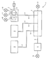
Nachfolgend wird ein Ausführungsbeispiel der Erfindung näher erläutert. Darin zeigt die einzige Figur ein Blockschaltbild einer Rufanlage auf Basis einer digitalen Telekommunikationsanlage.An exemplary embodiment of the invention is described in more detail below explained. The only figure shows a block diagram a call system based on a digital telecommunications system.
Das Kernstück einer stark vereinfacht dargestellten Rufanlage
1 ist eine digitale Vermittlungsanlage 2. Die Vermittlungsanlage
2 ist sternförmig mit mehreren Endgeräten 3,3' verbunden,
von denen nur das Endgerät 3 detaillierter ausgeführt
ist. Die baugleichen Endgeräte 3' sind aus Gründen der Vereinfachung
nur angedeutet. Die jedes Endgerät 3,3' mit der
Vermittlungsanlage 2 verbindenden Datenleitungen 4 sind gemäß
der bei einer digitalen Anlage gebräuchlichen Technik durch
So oder UP0/E-Schnittstellen ausgebildet. Die Vermittlungsanlage
2 steht weiterhin über eine LAN-Leitung 5 mit
einem Applikations-Server 6 in Verbindung. Die LAN-Leitung 5
ist dabei in einer für ein gewöhnliches LAN (local area network)
Computernetz gebräuchlichen Technik ausgeführt. Der
Datentransfer zwischen der Vermittlungsanlage 2 und dem Applikations-Server
6 beruht dabei auf dem in Computernetzen
weit verbreiteten TCP/IP-Standard.The core of a call system 1 shown in a highly simplified manner is a
Die Rufanlage 1 in ihrer Grundfunktion eine gewöhnliche digitale
Telekommunikations(Tk)-Anlage, insbesondere Siemens Hi-PATH-Anlage
mit UP0/E-Schnittstellen. Das Endgerät 3 ist mit
einer ersten Anschalteeinheit 7 versehen, die Daten mit der
Vermittlungsanlage 2 austauschen kann, und die zur Dateneingabe
und Datenausgabe auf nicht näher dargestellte Weise mit
einem Lautsprecher, einem Mikrofon sowie einem Tastenfeld
verbunden ist. Über das Endgerät 3 können somit normale Telefongespräche
geführt werden. Alternativ ist als Endgerät 3
eine so genannte "Zimmeranschaltung" vorgesehen, bei der das
Endgerät 3 nicht mit einer Sprechfunktion ausgerüstet ist.The basic function of call system 1 is an ordinary digital telecommunications (PBX) system, in particular a Siemens Hi-PATH system with U P0 / E interfaces. The
Zur Auslösung eines Not- oder Pflegerufs ist die Anschalteeinheit
7 über eine Rufleitung 8 mit einem Rufauslöser verbunden,
der durch eine Auslösetaste 9 gebildet ist. Die Anschalteeinheit
7, die Rufleitung 8 und die Auslösetaste 9
bilden somit eine Rufauslöseeinheit. Die Auslösetaste 9 kann
eine der Funktionstasten des Endgerätes 3 sein oder - wie
dargestellt - außerhalb des Endgerätes 3 angeordnet sein. Bei
Betätigung der Auslösetaste 9 wird vom Endgerät 3 zunächst
direkt, also nicht über die Vermittlungsanlage 2, ein
Rufmelder 10 betätigt. Als Rufmelder 10 dient dabei zum einen
ein in Krankenhäusern und Pflegeheimen gebräuchliches Zimmerlicht.
Optional werden weitere Lichtmeldungen, z.B. in einem
Stationszimmer, sowie ein akustisches Rufsignal aktiviert.
Weiterhin sendet die Anschalteeinheit 7 ein Rufsignal über
die Datenleitung 4 an die Vermittlungsanlage 2, von wo der
Ruf über die LAN-Leitung 5 an den Applikations-Server 6 weitergegeben
wird. Durch ein im Applikations-Server 6 installiertes
Rufleitsystem werden nun weitere Schritte ausgelöst,
wie z.B. die Übermittlung des Not- oder Pflegerufs als Rufweiterleitung
an ein weiteres Endgerät 3'. Weiterhin können
andere Meldesysteme wie DECT-Endgeräte, Personensuchgeräte,
über Amtsleitungen erreichbare Geräte etc. aktiviert werden. The interface unit is used to trigger an emergency or
Um einen Fehler der Verbindung zur Auslösetaste 9 frühzeitig
zu erkennen, ist die Rufleitung 8 schleifenstromüberwacht.
D.h., dass unabhängig vom aktuellen Betriebszustand der Auslösetaste
9 ein kontinuierlicher Prüfstrom durch die Rufleitung
8 und die Auslösetaste 9 geleitet wird. Eine Schleifenstromüberwachung
wird technisch beispielsweise dadurch realisiert,
dass dem nicht näher dargestellten Schaltkontakt der
Auslösetaste 9 ein hoher Widerstand parallel geschaltet ist,
über den der Prüfstrom fließt. Eine Fehlfunktion innerhalb
der Rufleitung 8 wird von der Anschalteeinheit 7 daran erkannt,
dass der Prüfstrom unterbrochen ist. In diesem Fall
aktiviert die Anschalteeinheit 7 einen Fehlermelder 11, der
wie der Rufmelder 10, durch ein Licht- und/oder Tonsignal
realisiert und auch im Rufmelder 10 integriert sein kann. Die
Datenleitung 4 wird bei der Tk-Anlage standardgemäß sowohl
seitens der Anschalteeinheit 7 als auch seitens der Vermittlungsanlage
2 ständig überwacht, indem periodisch Telegramme
zwischen der Anschalteeinheit 7 und der Vermittlungsanlage 2
ausgetauscht werden. Bei nicht ordnungsgemäßer Quittierung
der von der Anschalteeinheit 7 ausgesandten Telegramme aktiviert
diese wiederum den Fehlermelder 11, so dass eine Unterbrechung
der Datenleitung 4 oder ein Ausfall der Vermittlungsanlage
2 angezeigt wird. Ebenso aktiviert die Vermittlungsanlage
2 bei nicht ordnungsgemäßer Quittierung der von
der Vermittlungsanlage 2 an die Anschalteeinheit 7 gesandten
Telegramme einen mit der Vermittlungsanlage 2 verbundenen
Fehlermelder 12 und meldet somit eine Unterbrechung der Datenleitung
4 oder den Ausfall der Anschalteeinheit 7.To detect an error in the connection to the release button 9 early
can be seen, the
Zur Überwachung der Verbindung zwischen der Vermittlungsanlage
2 und dem Applikations-Server 6 ist innerhalb des Endgerätes
3 eine zweite Anschalteeinheit 13 vorgesehen. Die Anschalteeinheit
13 ist über eine ebenfalls als digitale Telefonschnittstelle
ausgeführte Prüfleitung 14 mit der Vermittlungsanlage
2 verbunden. Die Anschalteeinheit 13 ist wie die
Anschalteeinheit 7 gemäß digitaler Tk-Technologie zum Datenaustausch
mit der Vermittlungsanlage 2 vorgesehen. Die Anschalteeinheit
13, die in so genannter "embedded Technology"
als Mikrochip ausgeführt ist, ist dabei derart konfiguriert,
dass sie periodisch Prüfdaten über die Prüfleitung 14, die
Vermittlungsanlage 2 und die LAN-Leitung 5 an den Applikations-Server
6 sendet und die Quittierung dieser Prüfdaten
überwacht. Die Funktionen der Anschalteeinheiten 7 und 13
können auch als Software-Module auf einer einzigen Controller-Karte
vorgesehen sein. Die Datenleitung 4 und die Prüfleitung
14 sind dabei i.A. nicht physikalisch getrennt. Die
ordnungsgemäße Quittierung der von der Anschalteeinheit 13
ausgesandten Prüfdaten setzt voraus, dass die Prüfleitung 14,
die Vermittlungsanlage 2, die LAN-Leitung 5 sowie der Applikations-Server
6 fehlerfrei funktionieren. Ist dies nicht der
Fall, so aktiviert die Anschalteeinheit 13 einen weiteren
Fehlermelder 15. Ein Ausfall der Anschalteeinheit 13 wiederum
wird standardmäßig von der Vermittlungsanlage 2 erkannt.
Funktionsstörungen innerhalb des Applikations-Servers 6 werden
zudem vom Applikations-Server 6 über einen mit diesem
verbundenen Fehlermelder 16 angezeigt.To monitor the connection between the switching
Somit ist der gesamte Nachrichtenpfad ausgehend von der Auslösetaste
9 über die Anschalteeinheit 7, die Datenleitung 4,
die Vermittlungsanlage 2, die LAN-Leitung 5 zum Applikations-Server
6 in redundanter Weise überwacht. Insbesondere sind
die Sicherheitsanforderungen der VDE 0834 erfüllt. Im Fehlerfall
wird ein Teil der Fehlermelder 11,12,15 und 16 in charakteristischer
Weise aktiviert, so dass über dieses charakteristische
Fehleranzeigemuster die Fehlerquelle schnell lokalisierbar
ist.Thus, the entire message path is from the trigger button
9 via the
Claims (11)
Applications Claiming Priority (2)
| Application Number | Priority Date | Filing Date | Title |
|---|---|---|---|
| DE10242534 | 2002-09-12 | ||
| DE10242534A DE10242534A1 (en) | 2002-09-12 | 2002-09-12 | Call system based on a digital telecommunications system |
Publications (3)
| Publication Number | Publication Date |
|---|---|
| EP1400941A2 true EP1400941A2 (en) | 2004-03-24 |
| EP1400941A3 EP1400941A3 (en) | 2004-07-21 |
| EP1400941B1 EP1400941B1 (en) | 2009-03-11 |
Family
ID=31895935
Family Applications (1)
| Application Number | Title | Priority Date | Filing Date |
|---|---|---|---|
| EP03020348A Expired - Lifetime EP1400941B1 (en) | 2002-09-12 | 2003-09-09 | Calling device in a digital communication network |
Country Status (3)
| Country | Link |
|---|---|
| EP (1) | EP1400941B1 (en) |
| AT (1) | ATE425524T1 (en) |
| DE (2) | DE10242534A1 (en) |
Cited By (3)
| Publication number | Priority date | Publication date | Assignee | Title |
|---|---|---|---|---|
| EP2006816A1 (en) * | 2007-06-18 | 2008-12-24 | Siemens Aktiengesellschaft | Paging system for a care facility |
| EP2887242A1 (en) * | 2013-12-23 | 2015-06-24 | Televic Healthcare NV | Hand call unit |
| EP2976992A1 (en) * | 2014-07-25 | 2016-01-27 | Televic Healthcare NV | Nurse call system having local operation mode |
Families Citing this family (2)
| Publication number | Priority date | Publication date | Assignee | Title |
|---|---|---|---|---|
| CN110620843A (en) * | 2019-09-03 | 2019-12-27 | 蔡文伟 | Method for associating mobile phone calling ambulance request to APP or public number |
| DE102021202155B3 (en) | 2021-03-05 | 2022-04-14 | Sören Maurer | network module |
Citations (4)
| Publication number | Priority date | Publication date | Assignee | Title |
|---|---|---|---|---|
| US5692126A (en) * | 1995-01-24 | 1997-11-25 | Bell Atlantic Network Services, Inc. | ISDN access to fast packet data network |
| DE19735668A1 (en) * | 1997-08-16 | 1999-02-18 | Bosch Gmbh Robert | Paging system |
| US5987519A (en) * | 1996-09-20 | 1999-11-16 | Georgia Tech Research Corporation | Telemedicine system using voice video and data encapsulation and de-encapsulation for communicating medical information between central monitoring stations and remote patient monitoring stations |
| DE19924127A1 (en) * | 1999-05-26 | 2000-12-14 | Ackermann Albert Gmbh Co | Communication network for the care sector |
-
2002
- 2002-09-12 DE DE10242534A patent/DE10242534A1/en not_active Ceased
-
2003
- 2003-09-09 DE DE50311268T patent/DE50311268D1/en not_active Expired - Lifetime
- 2003-09-09 AT AT03020348T patent/ATE425524T1/en not_active IP Right Cessation
- 2003-09-09 EP EP03020348A patent/EP1400941B1/en not_active Expired - Lifetime
Patent Citations (4)
| Publication number | Priority date | Publication date | Assignee | Title |
|---|---|---|---|---|
| US5692126A (en) * | 1995-01-24 | 1997-11-25 | Bell Atlantic Network Services, Inc. | ISDN access to fast packet data network |
| US5987519A (en) * | 1996-09-20 | 1999-11-16 | Georgia Tech Research Corporation | Telemedicine system using voice video and data encapsulation and de-encapsulation for communicating medical information between central monitoring stations and remote patient monitoring stations |
| DE19735668A1 (en) * | 1997-08-16 | 1999-02-18 | Bosch Gmbh Robert | Paging system |
| DE19924127A1 (en) * | 1999-05-26 | 2000-12-14 | Ackermann Albert Gmbh Co | Communication network for the care sector |
Cited By (4)
| Publication number | Priority date | Publication date | Assignee | Title |
|---|---|---|---|---|
| EP2006816A1 (en) * | 2007-06-18 | 2008-12-24 | Siemens Aktiengesellschaft | Paging system for a care facility |
| EP2887242A1 (en) * | 2013-12-23 | 2015-06-24 | Televic Healthcare NV | Hand call unit |
| EP2976992A1 (en) * | 2014-07-25 | 2016-01-27 | Televic Healthcare NV | Nurse call system having local operation mode |
| EP2976996A1 (en) * | 2014-07-25 | 2016-01-27 | Televic Healthcare NV | Nurse call system having local operation mode |
Also Published As
| Publication number | Publication date |
|---|---|
| EP1400941B1 (en) | 2009-03-11 |
| DE10242534A1 (en) | 2004-03-25 |
| DE50311268D1 (en) | 2009-04-23 |
| EP1400941A3 (en) | 2004-07-21 |
| ATE425524T1 (en) | 2009-03-15 |
Similar Documents
| Publication | Publication Date | Title |
|---|---|---|
| EP2720094B1 (en) | Safety system | |
| EP2720051B1 (en) | Safety system | |
| DE19636819C2 (en) | Computer controlled telephone set | |
| EP1222542A1 (en) | Method for imposing the fail-silent characteristic in a distributed computer system and distribution unit in such a system | |
| EP0837394A2 (en) | Failsafe bus system | |
| DE19908179A1 (en) | Subscriber control unit for home security system | |
| EP0668706A2 (en) | Network terminal | |
| EP1400941B1 (en) | Calling device in a digital communication network | |
| EP0797178B1 (en) | Telecommunity alarm system with several safety monitoring modems | |
| DE2815183A1 (en) | ALARM, SECURITY AND MONITORING SYSTEM | |
| DE3633057C2 (en) | Circuit arrangement for the transmission of information technology signals | |
| WO1998030011A2 (en) | Method for monitoring an object by means of a digital data network | |
| DE4333580C2 (en) | Method and system for automatically monitoring at least one computer | |
| JP3733835B2 (en) | Elevator remote monitoring system | |
| EP0758518B1 (en) | Telecommunication system | |
| EP0475135B1 (en) | Transmission system for connection network in communication networks | |
| DE4341322A1 (en) | Alarm and emergency call transmission system | |
| DE10024487B4 (en) | Method and device for the remote maintenance, monitoring and / or operation of emergency call devices grouped in emergency call systems | |
| WO1998045983A2 (en) | Data communication link in a hierarchical communications network with a bus operated using an interrogation/response protocol, the so-called polling protocol | |
| DE1802999C (en) | Circuit arrangement for centrally controlled switching systems, in particular telephone switching systems, each with at least one program and / or stand-alone memory | |
| DE102004035124A1 (en) | Monitoring device for analog telecommunications terminal has switching arrangement that electrically loads respective subscriber connection on collapse of loop current for call release | |
| DE3733467C2 (en) | ||
| DE10026648B4 (en) | Method for remote maintenance, monitoring and / or operation of emergency call devices grouped in emergency call systems | |
| EP0969648B1 (en) | Method and system to secure a telecommunication link | |
| EP2006816A1 (en) | Paging system for a care facility |
Legal Events
| Date | Code | Title | Description |
|---|---|---|---|
| PUAI | Public reference made under article 153(3) epc to a published international application that has entered the european phase |
Free format text: ORIGINAL CODE: 0009012 |
|
| AK | Designated contracting states |
Kind code of ref document: A2 Designated state(s): AT BE BG CH CY CZ DE DK EE ES FI FR GB GR HU IE IT LI LU MC NL PT RO SE SI SK TR |
|
| AX | Request for extension of the european patent |
Extension state: AL LT LV MK |
|
| PUAL | Search report despatched |
Free format text: ORIGINAL CODE: 0009013 |
|
| AK | Designated contracting states |
Kind code of ref document: A3 Designated state(s): AT BE BG CH CY CZ DE DK EE ES FI FR GB GR HU IE IT LI LU MC NL PT RO SE SI SK TR |
|
| AX | Request for extension of the european patent |
Extension state: AL LT LV MK |
|
| RIC1 | Information provided on ipc code assigned before grant |
Ipc: 7G 08B 5/22 B Ipc: 7G 08B 25/01 B Ipc: 7G 08B 25/08 A |
|
| 17P | Request for examination filed |
Effective date: 20040804 |
|
| AKX | Designation fees paid |
Designated state(s): AT BE BG CH CY CZ DE DK EE ES FI FR GB GR HU IE IT LI LU MC NL PT RO SE SI SK TR |
|
| GRAP | Despatch of communication of intention to grant a patent |
Free format text: ORIGINAL CODE: EPIDOSNIGR1 |
|
| GRAS | Grant fee paid |
Free format text: ORIGINAL CODE: EPIDOSNIGR3 |
|
| GRAA | (expected) grant |
Free format text: ORIGINAL CODE: 0009210 |
|
| AK | Designated contracting states |
Kind code of ref document: B1 Designated state(s): AT BE BG CH CY CZ DE DK EE ES FI FR GB GR HU IE IT LI LU MC NL PT RO SE SI SK TR |
|
| REG | Reference to a national code |
Ref country code: GB Ref legal event code: FG4D Free format text: NOT ENGLISH |
|
| REG | Reference to a national code |
Ref country code: CH Ref legal event code: EP |
|
| REG | Reference to a national code |
Ref country code: IE Ref legal event code: FG4D Free format text: LANGUAGE OF EP DOCUMENT: GERMAN |
|
| REF | Corresponds to: |
Ref document number: 50311268 Country of ref document: DE Date of ref document: 20090423 Kind code of ref document: P |
|
| PG25 | Lapsed in a contracting state [announced via postgrant information from national office to epo] |
Ref country code: NL Free format text: LAPSE BECAUSE OF FAILURE TO SUBMIT A TRANSLATION OF THE DESCRIPTION OR TO PAY THE FEE WITHIN THE PRESCRIBED TIME-LIMIT Effective date: 20090311 Ref country code: SI Free format text: LAPSE BECAUSE OF FAILURE TO SUBMIT A TRANSLATION OF THE DESCRIPTION OR TO PAY THE FEE WITHIN THE PRESCRIBED TIME-LIMIT Effective date: 20090311 Ref country code: FI Free format text: LAPSE BECAUSE OF FAILURE TO SUBMIT A TRANSLATION OF THE DESCRIPTION OR TO PAY THE FEE WITHIN THE PRESCRIBED TIME-LIMIT Effective date: 20090311 |
|
| NLV1 | Nl: lapsed or annulled due to failure to fulfill the requirements of art. 29p and 29m of the patents act | ||
| PG25 | Lapsed in a contracting state [announced via postgrant information from national office to epo] |
Ref country code: SE Free format text: LAPSE BECAUSE OF FAILURE TO SUBMIT A TRANSLATION OF THE DESCRIPTION OR TO PAY THE FEE WITHIN THE PRESCRIBED TIME-LIMIT Effective date: 20090611 |
|
| REG | Reference to a national code |
Ref country code: IE Ref legal event code: FD4D |
|
| PG25 | Lapsed in a contracting state [announced via postgrant information from national office to epo] |
Ref country code: IE Free format text: LAPSE BECAUSE OF FAILURE TO SUBMIT A TRANSLATION OF THE DESCRIPTION OR TO PAY THE FEE WITHIN THE PRESCRIBED TIME-LIMIT Effective date: 20090311 Ref country code: PT Free format text: LAPSE BECAUSE OF FAILURE TO SUBMIT A TRANSLATION OF THE DESCRIPTION OR TO PAY THE FEE WITHIN THE PRESCRIBED TIME-LIMIT Effective date: 20090824 Ref country code: ES Free format text: LAPSE BECAUSE OF FAILURE TO SUBMIT A TRANSLATION OF THE DESCRIPTION OR TO PAY THE FEE WITHIN THE PRESCRIBED TIME-LIMIT Effective date: 20090622 Ref country code: CZ Free format text: LAPSE BECAUSE OF FAILURE TO SUBMIT A TRANSLATION OF THE DESCRIPTION OR TO PAY THE FEE WITHIN THE PRESCRIBED TIME-LIMIT Effective date: 20090311 Ref country code: EE Free format text: LAPSE BECAUSE OF FAILURE TO SUBMIT A TRANSLATION OF THE DESCRIPTION OR TO PAY THE FEE WITHIN THE PRESCRIBED TIME-LIMIT Effective date: 20090311 |
|
| PG25 | Lapsed in a contracting state [announced via postgrant information from national office to epo] |
Ref country code: SK Free format text: LAPSE BECAUSE OF FAILURE TO SUBMIT A TRANSLATION OF THE DESCRIPTION OR TO PAY THE FEE WITHIN THE PRESCRIBED TIME-LIMIT Effective date: 20090311 Ref country code: RO Free format text: LAPSE BECAUSE OF FAILURE TO SUBMIT A TRANSLATION OF THE DESCRIPTION OR TO PAY THE FEE WITHIN THE PRESCRIBED TIME-LIMIT Effective date: 20090311 |
|
| PLBE | No opposition filed within time limit |
Free format text: ORIGINAL CODE: 0009261 |
|
| STAA | Information on the status of an ep patent application or granted ep patent |
Free format text: STATUS: NO OPPOSITION FILED WITHIN TIME LIMIT |
|
| PG25 | Lapsed in a contracting state [announced via postgrant information from national office to epo] |
Ref country code: DK Free format text: LAPSE BECAUSE OF FAILURE TO SUBMIT A TRANSLATION OF THE DESCRIPTION OR TO PAY THE FEE WITHIN THE PRESCRIBED TIME-LIMIT Effective date: 20090311 Ref country code: BG Free format text: LAPSE BECAUSE OF FAILURE TO SUBMIT A TRANSLATION OF THE DESCRIPTION OR TO PAY THE FEE WITHIN THE PRESCRIBED TIME-LIMIT Effective date: 20090611 |
|
| 26N | No opposition filed |
Effective date: 20091214 |
|
| BERE | Be: lapsed |
Owner name: SIEMENS A.G. Effective date: 20090930 |
|
| PG25 | Lapsed in a contracting state [announced via postgrant information from national office to epo] |
Ref country code: MC Free format text: LAPSE BECAUSE OF NON-PAYMENT OF DUE FEES Effective date: 20090930 |
|
| REG | Reference to a national code |
Ref country code: CH Ref legal event code: PL |
|
| GBPC | Gb: european patent ceased through non-payment of renewal fee |
Effective date: 20090909 |
|
| REG | Reference to a national code |
Ref country code: FR Ref legal event code: ST Effective date: 20100531 |
|
| PG25 | Lapsed in a contracting state [announced via postgrant information from national office to epo] |
Ref country code: FR Free format text: LAPSE BECAUSE OF NON-PAYMENT OF DUE FEES Effective date: 20090930 |
|
| PG25 | Lapsed in a contracting state [announced via postgrant information from national office to epo] |
Ref country code: BE Free format text: LAPSE BECAUSE OF NON-PAYMENT OF DUE FEES Effective date: 20090930 |
|
| PG25 | Lapsed in a contracting state [announced via postgrant information from national office to epo] |
Ref country code: CH Free format text: LAPSE BECAUSE OF NON-PAYMENT OF DUE FEES Effective date: 20090930 Ref country code: LI Free format text: LAPSE BECAUSE OF NON-PAYMENT OF DUE FEES Effective date: 20090930 Ref country code: GR Free format text: LAPSE BECAUSE OF FAILURE TO SUBMIT A TRANSLATION OF THE DESCRIPTION OR TO PAY THE FEE WITHIN THE PRESCRIBED TIME-LIMIT Effective date: 20090612 |
|
| PG25 | Lapsed in a contracting state [announced via postgrant information from national office to epo] |
Ref country code: AT Free format text: LAPSE BECAUSE OF NON-PAYMENT OF DUE FEES Effective date: 20090909 Ref country code: GB Free format text: LAPSE BECAUSE OF NON-PAYMENT OF DUE FEES Effective date: 20090909 |
|
| PG25 | Lapsed in a contracting state [announced via postgrant information from national office to epo] |
Ref country code: IT Free format text: LAPSE BECAUSE OF FAILURE TO SUBMIT A TRANSLATION OF THE DESCRIPTION OR TO PAY THE FEE WITHIN THE PRESCRIBED TIME-LIMIT Effective date: 20090311 |
|
| PG25 | Lapsed in a contracting state [announced via postgrant information from national office to epo] |
Ref country code: LU Free format text: LAPSE BECAUSE OF NON-PAYMENT OF DUE FEES Effective date: 20090909 |
|
| PG25 | Lapsed in a contracting state [announced via postgrant information from national office to epo] |
Ref country code: HU Free format text: LAPSE BECAUSE OF FAILURE TO SUBMIT A TRANSLATION OF THE DESCRIPTION OR TO PAY THE FEE WITHIN THE PRESCRIBED TIME-LIMIT Effective date: 20090912 |
|
| PG25 | Lapsed in a contracting state [announced via postgrant information from national office to epo] |
Ref country code: TR Free format text: LAPSE BECAUSE OF FAILURE TO SUBMIT A TRANSLATION OF THE DESCRIPTION OR TO PAY THE FEE WITHIN THE PRESCRIBED TIME-LIMIT Effective date: 20090311 |
|
| PG25 | Lapsed in a contracting state [announced via postgrant information from national office to epo] |
Ref country code: CY Free format text: LAPSE BECAUSE OF FAILURE TO SUBMIT A TRANSLATION OF THE DESCRIPTION OR TO PAY THE FEE WITHIN THE PRESCRIBED TIME-LIMIT Effective date: 20090311 |
|
| PGFP | Annual fee paid to national office [announced via postgrant information from national office to epo] |
Ref country code: DE Payment date: 20161121 Year of fee payment: 14 |
|
| REG | Reference to a national code |
Ref country code: DE Ref legal event code: R119 Ref document number: 50311268 Country of ref document: DE |
|
| PG25 | Lapsed in a contracting state [announced via postgrant information from national office to epo] |
Ref country code: DE Free format text: LAPSE BECAUSE OF NON-PAYMENT OF DUE FEES Effective date: 20180404 |