EP1401033A2 - Organic electroluminescent device and manufacturing method thereof - Google Patents
Organic electroluminescent device and manufacturing method thereof Download PDFInfo
- Publication number
- EP1401033A2 EP1401033A2 EP20030252222 EP03252222A EP1401033A2 EP 1401033 A2 EP1401033 A2 EP 1401033A2 EP 20030252222 EP20030252222 EP 20030252222 EP 03252222 A EP03252222 A EP 03252222A EP 1401033 A2 EP1401033 A2 EP 1401033A2
- Authority
- EP
- European Patent Office
- Prior art keywords
- layer
- organic
- electrode
- forming
- emission layer
- Prior art date
- Legal status (The legal status is an assumption and is not a legal conclusion. Google has not performed a legal analysis and makes no representation as to the accuracy of the status listed.)
- Ceased
Links
Images


Classifications
-
- H—ELECTRICITY
- H05—ELECTRIC TECHNIQUES NOT OTHERWISE PROVIDED FOR
- H05B—ELECTRIC HEATING; ELECTRIC LIGHT SOURCES NOT OTHERWISE PROVIDED FOR; CIRCUIT ARRANGEMENTS FOR ELECTRIC LIGHT SOURCES, IN GENERAL
- H05B33/00—Electroluminescent light sources
- H05B33/12—Light sources with substantially two-dimensional radiating surfaces
- H05B33/22—Light sources with substantially two-dimensional radiating surfaces characterised by the chemical or physical composition or the arrangement of auxiliary dielectric or reflective layers
-
- H—ELECTRICITY
- H10—SEMICONDUCTOR DEVICES; ELECTRIC SOLID-STATE DEVICES NOT OTHERWISE PROVIDED FOR
- H10K—ORGANIC ELECTRIC SOLID-STATE DEVICES
- H10K50/00—Organic light-emitting devices
- H10K50/10—OLEDs or polymer light-emitting diodes [PLED]
- H10K50/18—Carrier blocking layers
-
- H—ELECTRICITY
- H10—SEMICONDUCTOR DEVICES; ELECTRIC SOLID-STATE DEVICES NOT OTHERWISE PROVIDED FOR
- H10K—ORGANIC ELECTRIC SOLID-STATE DEVICES
- H10K50/00—Organic light-emitting devices
- H10K50/10—OLEDs or polymer light-emitting diodes [PLED]
- H10K50/14—Carrier transporting layers
-
- H—ELECTRICITY
- H10—SEMICONDUCTOR DEVICES; ELECTRIC SOLID-STATE DEVICES NOT OTHERWISE PROVIDED FOR
- H10K—ORGANIC ELECTRIC SOLID-STATE DEVICES
- H10K50/00—Organic light-emitting devices
- H10K50/80—Constructional details
- H10K50/805—Electrodes
- H10K50/82—Cathodes
-
- H—ELECTRICITY
- H10—SEMICONDUCTOR DEVICES; ELECTRIC SOLID-STATE DEVICES NOT OTHERWISE PROVIDED FOR
- H10K—ORGANIC ELECTRIC SOLID-STATE DEVICES
- H10K59/00—Integrated devices, or assemblies of multiple devices, comprising at least one organic light-emitting element covered by group H10K50/00
- H10K59/10—OLED displays
- H10K59/12—Active-matrix OLED [AMOLED] displays
-
- H—ELECTRICITY
- H10—SEMICONDUCTOR DEVICES; ELECTRIC SOLID-STATE DEVICES NOT OTHERWISE PROVIDED FOR
- H10K—ORGANIC ELECTRIC SOLID-STATE DEVICES
- H10K71/00—Manufacture or treatment specially adapted for the organic devices covered by this subclass
-
- H—ELECTRICITY
- H10—SEMICONDUCTOR DEVICES; ELECTRIC SOLID-STATE DEVICES NOT OTHERWISE PROVIDED FOR
- H10K—ORGANIC ELECTRIC SOLID-STATE DEVICES
- H10K85/00—Organic materials used in the body or electrodes of devices covered by this subclass
- H10K85/10—Organic polymers or oligomers
- H10K85/111—Organic polymers or oligomers comprising aromatic, heteroaromatic, or aryl chains, e.g. polyaniline, polyphenylene or polyphenylene vinylene
- H10K85/113—Heteroaromatic compounds comprising sulfur or selene, e.g. polythiophene
- H10K85/1135—Polyethylene dioxythiophene [PEDOT]; Derivatives thereof
-
- H—ELECTRICITY
- H10—SEMICONDUCTOR DEVICES; ELECTRIC SOLID-STATE DEVICES NOT OTHERWISE PROVIDED FOR
- H10K—ORGANIC ELECTRIC SOLID-STATE DEVICES
- H10K85/00—Organic materials used in the body or electrodes of devices covered by this subclass
- H10K85/30—Coordination compounds
- H10K85/321—Metal complexes comprising a group IIIA element, e.g. Tris (8-hydroxyquinoline) gallium [Gaq3]
- H10K85/324—Metal complexes comprising a group IIIA element, e.g. Tris (8-hydroxyquinoline) gallium [Gaq3] comprising aluminium, e.g. Alq3
-
- H—ELECTRICITY
- H10—SEMICONDUCTOR DEVICES; ELECTRIC SOLID-STATE DEVICES NOT OTHERWISE PROVIDED FOR
- H10K—ORGANIC ELECTRIC SOLID-STATE DEVICES
- H10K85/00—Organic materials used in the body or electrodes of devices covered by this subclass
- H10K85/60—Organic compounds having low molecular weight
- H10K85/615—Polycyclic condensed aromatic hydrocarbons, e.g. anthracene
- H10K85/621—Aromatic anhydride or imide compounds, e.g. perylene tetra-carboxylic dianhydride or perylene tetracarboxylic di-imide
-
- H—ELECTRICITY
- H10—SEMICONDUCTOR DEVICES; ELECTRIC SOLID-STATE DEVICES NOT OTHERWISE PROVIDED FOR
- H10K—ORGANIC ELECTRIC SOLID-STATE DEVICES
- H10K85/00—Organic materials used in the body or electrodes of devices covered by this subclass
- H10K85/60—Organic compounds having low molecular weight
- H10K85/649—Aromatic compounds comprising a hetero atom
- H10K85/656—Aromatic compounds comprising a hetero atom comprising two or more different heteroatoms per ring
- H10K85/6565—Oxadiazole compounds
-
- Y—GENERAL TAGGING OF NEW TECHNOLOGICAL DEVELOPMENTS; GENERAL TAGGING OF CROSS-SECTIONAL TECHNOLOGIES SPANNING OVER SEVERAL SECTIONS OF THE IPC; TECHNICAL SUBJECTS COVERED BY FORMER USPC CROSS-REFERENCE ART COLLECTIONS [XRACs] AND DIGESTS
- Y10—TECHNICAL SUBJECTS COVERED BY FORMER USPC
- Y10T—TECHNICAL SUBJECTS COVERED BY FORMER US CLASSIFICATION
- Y10T428/00—Stock material or miscellaneous articles
- Y10T428/26—Web or sheet containing structurally defined element or component, the element or component having a specified physical dimension
-
- Y—GENERAL TAGGING OF NEW TECHNOLOGICAL DEVELOPMENTS; GENERAL TAGGING OF CROSS-SECTIONAL TECHNOLOGIES SPANNING OVER SEVERAL SECTIONS OF THE IPC; TECHNICAL SUBJECTS COVERED BY FORMER USPC CROSS-REFERENCE ART COLLECTIONS [XRACs] AND DIGESTS
- Y10—TECHNICAL SUBJECTS COVERED BY FORMER USPC
- Y10T—TECHNICAL SUBJECTS COVERED BY FORMER US CLASSIFICATION
- Y10T428/00—Stock material or miscellaneous articles
- Y10T428/31504—Composite [nonstructural laminate]
- Y10T428/31678—Of metal
Abstract
Description
- The present invention relates to an organic electroluminescent (EL) device, and, more particularly, to an organic EL device having an emission layer comprising a polymer and having an improved lifetime characteristic.
- An electroluminescent (EL) device is a self-emission display using a phenomenon in which, when a current is applied to a fluorescent or phosphorescent organic compound film, light is emitted from the organic compound film by electron-hole recombination occurring. The EL device is lightweight, has non-complex components, and has a simplified manufacturing process, while exhibiting a high visibility and a wide viewing angle. Also, the EL device can present a motion picture display and can achieve a high color purity.
- The organic EL device can be divided into two types: a passive matrix (PM) type, and an active matrix (AM) type according to a driving method thereof.
- According to a PM drive type, a first set of electrodes and a second set of electrodes are arranged in a matrix configuration to cross each other to produce a pixel area at each intersection. When scan lines are sequentially selected, a pixel area selected by a data line signal instantaneously emits light. In a display apparatus of such a PM drive type, since the configuration and manufacturing process are simple, the manufacturing cost is advantageously low. However, a high resolution and large area display are difficult to achieve, and power consumption is high.
- According to an AM drive type, a plurality of thin film transistors (TFTs) and pixel electrodes electrically connected to the TFTs, are arranged at the respective intersections of scan lines and data lines, and common electrodes are entirely covered over the TFTs and pixel electrodes. Since a pixel area is indirectly driven by a TFT as a switching device, voltages applied to the respective pixels are completely independently sustained, and the respective pixels are independently driven according to electrical signals applied to scan lines and data lines. An AM driven organic EL device can achieve a high resolution and large area display and provides a good picture quality while having smaller power consumption and a longer lifetime, compared to a PM driven organic EL device.
- An organic EL device can also be divided into a low molecular (or a small molecular) organic EL device and a high molecular (or a polymeric) organic EL device according to a material used for forming an organic compound film.
- A low molecular weight organic EL device is basically constructed such that a low molecular weight emission layer is formed between a first electrode and a second electrode, a hole transport layer (HTL) is formed between the emission layer and the first electrode, and an electron transport layer (ETL) is formed between the emission layer and the second electrode, thereby improving efficiency and lifetime characteristics (U.S. Patent Nos. 4,356,429, 4,539,507, 4,720,432, and 4,769,292).
- A high molecular weight organic EL device, as disclosed in U.S. Patent No. 5,247,190, is constructed such that an emission layer is formed between a transparent, first electrode and a metallic, second electrode. However, such a high molecular weight EL device has poor efficiency and lifetime characteristics because work functions of the first and second electrodes and the highest occupied molecular orbital (HOMO) and the lowest unoccupied molecular orbital (LUMO) values of a polymer forming the emission layer are different from each other. To solve these problems, there has been proposed a method in which a metal having a work function value similar to the LUMO value of a polymer forming the emission layer is used as a second electrode forming material.
- However, if the LUMO value of one selected from red (R), green (G) and blue (B) polymeric emission layers is adjusted to be substantially the same as a work function value of a cathode, the efficiencies of non-selected polymeric emission layers may deteriorate.
- For realizing a full-color display using a polymeric organic EL device, an emission layer is formed by ink-jet printing (Japanese Patent Laid-open Publication No. 10-153967, WO 98/24271 and U.S. Patent No. 6,087,196). The use of ink-jet printing reduces an amount of an emission layer forming material and allows large area patterning.
- Another method for realizing a full-color display using a polymeric organic EL device is disclosed in U.S. Patent No. 5,998,085, in which an emission layer is formed by laser induced thermal imaging (LITI).
- As described above, in the polymeric organic EL device, a polymer for forming an emission layer acts as both an electron transport layer and a hole transport layer. Thus, a single emission layer is generally formed between the first and the second electrodes.
- However, use of such a single emission layer makes a metal diffuse into the emission layer during deposition of the metal, considerably deteriorating a stability of the EL device (Surface Science 500 (2002) 904-922).
- U.S. Patent No. 5,807,627 discloses a polymeric organic EL device having a four-layered structure in which a first charge carrier injection layer, first and second layers made of a semiconductive conjugated PPV-based polymer, and a second charge carrier injection layer are sequentially stacked between the first and the second electrodes. As described above, a multilayered film that includes a charge carrier injection layer is formed between the first and the second electrodes to increase the efficiency of an organic EL device that is hindered by a polymer's poor capability in transporting electrons and holes.
- In the organic EL device, however, to prevent a lower layer from being damaged when forming an upper layer in the manufacture of a multilayered film, polymers having different solubilities in an organic solvent for spin-coating should be used as materials for forming the upper and lower layers. Also, since spin-coating is employed in film formation, patterning of an emission layer is impossible, making full-color display difficult.
- The present invention provides an organic EL device having improved lifetime and efficiency characteristics.
- Additional aspects and advantages of the invention will be set forth in part in the description which follows and, in part, will be obvious from the description, or may be learned by practice of the invention.
- In accordance with an aspect of the present invention, an organic EL device includes a substrate, a first electrode formed on the substrate, an emission layer comprising a polymer formed on the first electrode, a second electrode formed on the emission layer, and a metal infiltration preventing layer, formed between the emission layer and the second electrode, to prevent a second electrode metal from infiltrating into the emission layer.
- The metal infiltration preventing layer may include at least one layer selected from a hole blocking layer and an electron transport layer.
- The organic EL device according to the present invention may further comprise a hole injection layer between the first electrode and the emission layer.
- Also, the organic EL device according to the present invention may further comprise an organic soluble hole transport layer between the hole injection layer and the emission layer.
- In one embodiment, a TFT is disposed between the substrate and the first electrode, an insulator layer is disposed on the TFT, and the first electrode is connected to source/drain electrodes of the TFT through a via hole of the insulator layer.
- In accordance with another aspect of the present invention, a method of forming an organic EL device comprises forming a first electrode on a substrate, forming an emission layer comprising a polymer on the first electrode, forming a metal infiltration preventing layer on the emission layer, and forming a second electrode on the metal infiltration preventing layer.
- The organic EL device forming method according to the present invention may further include forming a hole injection layer between the first electrode and the emission layer. The hole injection layer may be formed by spin-coating a hole injection layer forming composition and annealing at 100 to 200°C.
- Also, the organic EL device forming method according to the present invention may further include forming an organic soluble hole transport layer between the hole injection layer and the emission layer.
- The emission layer may be formed by spin-coating, laser induced thermal imaging or ink-jet printing.
- Also, the metal infiltration preventing layer may be formed by spin-coating or deposition. Prior to forming the metal infiltration preventing layer, annealing may be performed at 70 to 200°C.
- These and/or other features and advantages of the present invention will become apparent and more readily appreciated from the following description of the embodiments, with reference to the accompanying drawings in which:
- FIGs. 1A-1E are schematic diagrams of a stack structure of an organic EL device according to an embodiment of the present invention;
- FIG. 2 is a schematic diagram illustrating a procedure of forming an emission layer according to an embodiment of the present invention by thermal transfer;
- FIG. 3 is a schematic diagram of an organic EL device of an AM drive type according to an embodiment of the present invention;
- FIGs. 4A and 4B illustrate a change in luminance over time in organic EL devices according to Comparative Example 1 and Example 12 of the present invention; and
- FIG. 5 illustrates a change in luminance over time in organic EL devices according to Comparative Example 1 and Examples 16 and 17 of the present invention.
-
- Reference will now be made in detail to the present preferred embodiments of the present invention, examples of which are illustrated in the accompanying drawings, wherein like reference numerals refer to the like elements throughout. The embodiments are described below in order to explain the present invention by referring to the figures.
- An organic EL device according to an embodiment of the present invention has a metal infiltration preventing layer between an emission layer and a second electrode. The metal infiltration preventing layer preferably includes at least one layer selected from the group consisting of a hole blocking layer and an electron transport layer, but is not limited in view of a stack structure and composition of the layer provided that the layer selected is capable of preventing a metal for forming a second electrode from infiltrating into the emission layer.
- In the organic EL device employing a polymeric emission layer, it is quite difficult to select a material for a common cathode, which will now be described in more detail. The range of the LUMO value of a polymer is broad, that is, from 2.3 to 3.5 eV. Thus, if the LUMO value of a blue (B) emission layer is adjusted to be substantially the same as the work function value of a cathode, the emission efficiencies of green (G) and red (R) emission layers deteriorate. However, according to the present invention, since the hole blocking layer and the electron transport layer serve as buffer layers, a common electrode can be used irrespective of R, G and B emission layers, while exhibiting excellent efficiency and lifetime characteristics. That is, the organic EL device according to the present invention provides a relatively wide option in selecting materials for a common electrode.
- FIGs. 1A-1E are schematic diagrams of a stack structure of an organic EL device according to an embodiment of the present invention. Referring to FIG. 1A, an
emission layer 12 comprising a polymer is stacked on afirst electrode 10, ahole blocking layer 13 as a metal infiltration preventing layer is stacked on theemission layer 12, and thesecond electrode 14 is formed thereon. - An organic EL device shown in FIG. 1B further includes a
hole injection layer 11 between thefirst electrode 10 and theemission layer 12. - An organic EL device shown in FIG. 1C has the same stack structure as that shown in FIG. 1B, except that an
electron transport layer 15 is disposed as a metal infiltration preventing layer, instead of thehole blocking layer 13. - An organic EL device shown in FIG. 1D has the same stack structure as that shown in FIG. 1B, except that a bilayer structure having both a
hole blocking layer 13 and anelectron transport layer 15 sequentially stacked is used as a metal infiltration preventing layer, instead of a single layer consisting of thehole blocking layer 13. - An organic EL device shown in FIG. 1E has the same stack structure as that shown in FIG. 1D, except that an organic soluble
hole transport layer 16 is further disposed between theemission layer 12 and thehole injection layer 11. The organic solublehole transport layer 16 serves to prevent impurities from infiltrating into theemission layer 12 from thehole injection layer 11. - Methods of manufacturing organic EL devices having a stack structure shown in FIGs. 1A through 1E will now be described. First, a patterned
first electrode 10 is formed on a substrate (not shown). The substrate is a substrate used in a general organic EL device, preferably a glass substrate or a transparent plastic substrate having good transparency, surface evenness, manageablility and being waterproof. The thickness of the substrate is preferably about 0.3 to 1.1 mm. - A material for forming the
first electrode 10 is a conductive metal or an oxide of the conductive metal capable of easily injecting holes, and examples thereof include ITO (Indium Tin Oxide), IZO (Indium Zinc Oxide), Ni, Pt, Au, lr, and the like. The substrate having thefirst electrode 10 is washed and then subjected to UV/O3 treatment. At the washing step, an organic solvent, such as isopropanol (IPA) or acetone, is generally used. - The
hole injection layer 11 is optionally formed on thefirst electrode 10 in the washed substrate. Thehole injection layer 11 reduces a contact resistance between thefirst electrode 10 and theemission layer 12, and increases a hole transporting capability of thefirst electrode 10 with respect to theemission layer 12, thus improving overall driving voltage and lifetime characteristics of the device. As a material for forming thehole injection layer 11, an aqueous material, such as PEDOT {poly(3, 4-ethylenedioxythiophene)}/PSS(polystyrene parasulfonate), or a starburst material, is used. Such a material is spin-coated on thefirst electrode 10 and is dried to form thehole injection layer 11. The thickness of thehole injection layer 11 is about 30 to 200 nm to obtain a desired level of hole injection characteristic. - The drying temperature is preferably about 100 to 250°C, more preferably approximately 200°C.
- The
emission layer 12 is formed on thehole injection layer 11. When forming theemission layer 12 by laser induced thermal imaging (LITI), the organic solublehole transport layer 16 may also be formed between theemission layer 12 and thehole injection layer 11, as shown in FIG. 1 E. An organic soluble hole injection layer or transport layer may be used without an aqueous hole injection layer. - As a material for forming the organic soluble
hole transport layer 16, any material having a hole transporting capability and having a good solubility in an organic solvent, such as toluene or xylene, can be used. Preferably, the material is a polymer having a hole transporting capability or a mixture of a polymer and a low molecular weight compound having a hole transporting capability. The polymer having a hole transporting capability is typically selected from the group consisting of arylamine-, perylene-, carbazole-, hydrazone-, stilbene- and pyrrole-based polymers and combinations thereof. The polymer for the mixture is generally selected from the group consisting of polystyrene, poly(styrene-butadiene) copolymer, polymethylmethacrylate, poly-α-methylstyrene, styrene-methylmethacrylate copolymer, polybutadiene, polycarbonate, polyethylterephthalate, polyestersulfonate, polyacrylate, fluorinated polyimide, transparent fluorine resin and transparent acryl resin and combinations thereof. The low molecular weight compound having a hole transporting capability is generally selected from the group consisting of arylamines, perylenes, carbazoles, stilbenes, pyrroles, starburst compounds containing derivatives and combinations thereof. The mixtures are preferably formed by dispersing 10 to 80 wt% of the low molecular weight compound in 10 to 20 wt% of the polymer. - The organic soluble
hole transport layer 16 is formed by spin-coating. The thickness of thehole transport layer 16 is about 10 to 200 nm, preferably 20 nm. - The
emission layer 12 is formed on thehole injection layer 11. In forming theemission layer 12, LITI, ink-jet coating, spin-coating or the like, may be employed. In the case of using LITI, the organic solublehole transport layer 16 may also be formed on thehole injection layer 11. - The method of forming the
emission layer 12 will now be described in more detail. Processing conditions for LITI are described, but not specifically limited, in Korean Patent No. 1998-051814 and U.S. Patent Nos. 5,998,085, 5,220,348, 5,256,506, 5,278,023 and 5,308,737, the disclosures of which are incorporated herein by reference. - As shown in FIG. 2, an
emission layer 22, aninterlayer insulator layer 26 and a light to heat conversion (LTHC)layer 27 are sequentially formed on asupport film 28 to produce a donor film. Theemission layer 22 coated on the donor film in a predetermined thickness is transferred to a substrate to form a patterned emission layer 22' on the substrate by LITI. The thickness of theemission layer 22 is preferably about 10 to 100 nm. In FIG. 2, reference numeral 23 denotes a hole injection layer,reference numeral 24 denotes a first electrode, andreference numeral 25 denotes a hole transport layer, respectively. - A method of forming an emission layer by ink-jet printing may be performed under the same processing conditions as in a conventional EL device, e.g., conditions described in U.S. Patent No. 6,087,196, the disclosure of which is incorporated herein by reference. A method of forming an emission layer by spin-coating will now be described.
- First, one composition selected from compositions for forming R, G and B emission layers is spin-coated on the entire surface of the hole injection layer, and dried. Then, the resultant product is patterned to form one of the R, G and B emission layers. Likewise, the remaining emission layers are formed. Each of the compositions for forming the R, G and B emission layers includes an emissive material and an organic solvent. Preferably, the organic solvent is selected such that underlying layers are not dissolved.
- Examples of the material for forming the emission layer according to the present invention include, but are not limited to, fluorene-based polymers, polyparaphenylene vinylenes or derivatives thereof, and spiro polyfluorene based polymers.
- Also, the material for forming the emission layer according to the present invention may further include a dopant such as optically inactive matrix polymers, host polymers and small molecules having a greater band gap than emissive polymers to induce energy transfer, hole transporting polymers and small molecules, or electron transporting polymers and small molecules. The content of the dopant may vary depending on a material for forming the emission layer, preferably 5 to 80 wt% based on the total weight of the emission layer forming material. If the content of dopant is outside the above range, emission characteristics of the EL device deteriorate to an undesirable level.
- Examples of the material for forming the emission layer according to the present invention include polystyrene, polystyrene-butadiene copolymer, polymethylmethacrylate, poly-α-methylstyrene, styrene-methyl methacrylate copolymer, polybutadiene, polycarbonate, polyethyleneterephthalate, polyestersulfonate, polysulfonate, polyacrylate, fluorinated polyimide, transparent fluorine based resin, transparent acryl based resin, arylamine, perylenes, pyrroles, hydrazones, carbazoles, stilbenes, starburst materials, oxadiazoles and the like.
- The thickness of the emission layer is preferably about 10 to 100 nm. If the thickness of the emission layer is less than 10 nm, the emission efficiency is lowered. If the thickness of the emission layer is greater than 100 nm, the driving voltage is undesirably increased.
- After forming the
emission layer 12, annealing at 70 to 200°C may be performed, improving the lifetime characteristic of the EL device. - A metal infiltration preventing layer is formed on the
emission layer 12. The metal infiltration preventing layer is ahole blocking layer 13 and/or anelectron transport layer 15 formed by deposition or spin-coating. Thehole blocking layer 13 prevents excitons generated from a fluorescent material from migrating to theelectron transport layer 15 or prevents holes from migrating to theelectron transport layer 15. - In the case of forming the
hole blocking layer 13 and/or theelectron transport layer 15 by deposition, a second electrode can also be formed using an open mask. Thus, since it is not necessary to perform a complex manufacturing process, e.g., a process using a fine metal mask can be used to simplify the overall manufacturing process. - When forming the
hole blocking layer 13 and/or theelectron transport layer 15 by spin-coating, materials for forming a hole blocking layer and an electron transport layer are respectively dissolved in a solvent to prepare compositions for forming the hole blocking layer and the electron transport layer, followed by spin-coating onto a substrate and drying. The solvent includes a polar aprotic solvent, such as IPA or ethanol, which does not dissolve an emission layer. - Examples of the material for forming the
hole blocking layer 13 include phenanthrolines (e.g., BCP manufactured by UDC CORP.), imidazoles, triazoles, oxadiazoles (e.g., PBD), aluminum complexes (UDC CORP.) BAlq having the following formula, and fluorinated compounds (e.g., CF-X or CF-Y manufactured by TOYOTA). In addition, any material having an ionizing potential of at least 0.5 eV greater than that of the material for forming an emission layer and having an intermediate electron affinity between the electron affinity of the emission layer and the electron affinity of the electron transport layer, may be used.


- Examples of the materials for forming the
electron transport layer 15 include oxazoles, isooxazoles, triazoles, isothiazoles, oxadiazoles, thiadiazoles, perylenes, aluminum complexes (e.g., Alq3 (tris(8-quinolinolato)-aluminum), BAlq, SAlq, Almq3, and gallium complexes (e.g., Gaq'2OPiv, Gaq'2Oac or 2(Gaq'2)).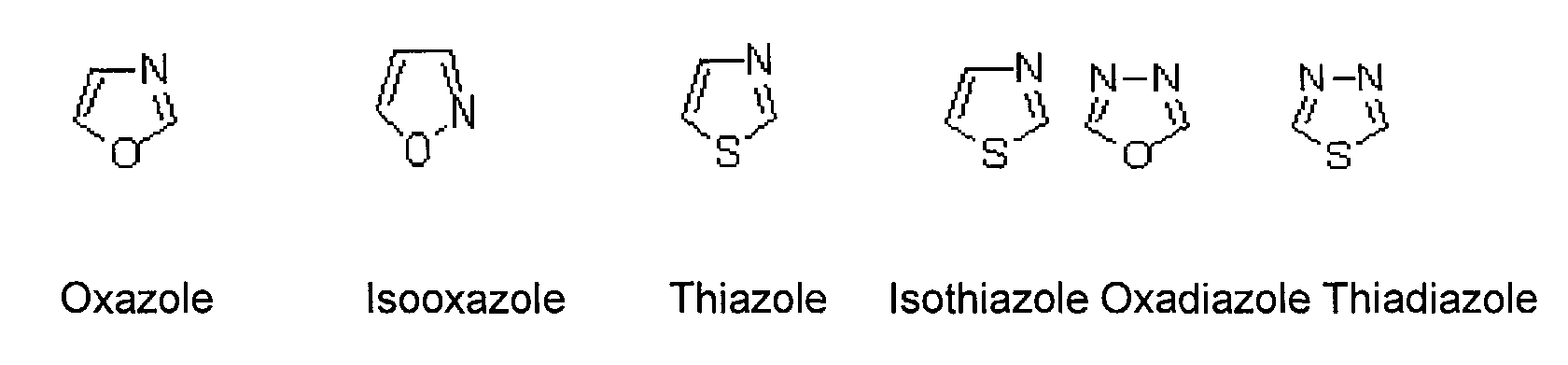


- The overall thickness of the metal infiltration preventing layer is about 0.1 to 50 nm, preferably 4 to 7 nm. If the thickness of the metal infiltration preventing layer is less than 0.1 nm, effects exhibited by various layers, including electron transporting capability or hole transporting capability, are lowered. If the thickness of the metal infiltration preventing layer is greater than 50 nm, color coordinates may change due to intrinsic illuminating effects from the metal infiltration preventing layer.
- As described above, after forming the metal infiltration preventing layer, the
second electrode 14 is formed thereon and the resultant product is encapsulated, thus completing an organic EL device. - The
second electrode 14 is formed by depositing a metal having a small work function, for example, Li, Ca, LiF/Ca, LiF/Al, Al, Mg/Ag, BaF2/Al, Yb, Mg, or Mg alloy. The thickness of thesecond electrode 14 is preferably about 5 to 300 nm. - FIG. 3 is a schematic diagram of an EL device of an AM drive type according to an embodiment of the present invention. Referring to FIG. 3, the organic EL device includes a
pixel area 20 where an image is displayed, and adriver area 40 which drives thepixel area 20. Thepixel area 20 includes atransparent substrate 308 and a plurality of insulator layers stacked thereon. The plurality of insulator layers include abuffer insulator layer 309, anintermediate insulator layer 311, aninterlayer insulator layer 312 and aplanarization layer 316 sequentially stacked. - A panel (pixel) area, including a first electrode, a hole injection layer, an emission layer and a second electrode, is formed on the
planarization layer 316. In more detail, ahole injection layer 303, anemission layer 304, ahole blocking layer 305, anelectron transport layer 306 and asecond electrode 307 are sequentially formed on afirst electrode 301. Thehole injection layer 303, theemission layer 304, thehole blocking layer 305, theelectron transport layer 306 and thesecond electrode 307 extend to thedriver area 40, as shown in FIG. 3.Reference numeral 317 denotes an insulator layer. - The
driver area 40 has TFTs for active driving. In other words, abuffer insulator layer 309 is formed on thetransparent substrate 308, and asemiconductor layer 310 is provided thereon. - A
gate electrode 315 is arranged above thesemiconductor layer 310 to correspond thereto. Theinterlayer insulator layer 312 covering thegate electrode 315, asource electrode 313 and adrain electrode 314 are formed at opposite sides of thesemiconductor layer 310 through acontact hole 313a, respectively. - The
planarization layer 316 is formed over thesource electrode 313 and thedrain electrode 314. Thefirst electrode 301 of thepixel area 20 is electrically connected to thedrain electrode 314 through a via hole 318. - The present invention will be further described with reference to the following examples; however, it should be noted that the present invention is not restricted by said examples.
- Examples 1-5 have the HBL layer and ETL layer thicknesses set forth in Table 1 and were prepared as follows. A patterned ITO substrate was washed and subjected to UV-O3 treatment for 15 minutes, followed by spin-coating a composition for forming a hole injection layer (PEDOT/PSS manufactured by BAYER) to a thickness of 62 nm at a rate of 5000 rpm, and drying at 200°C for 5 minutes, thus forming a hole injection layer.
- A composition for forming an organic soluble hole transport layer was spin coated onto the hole injection layer to a thickness of 25 nm at a rate of 4000 rpm, thus forming an organic soluble hole transport layer. As the composition for forming the organic soluble hole transport layer, a mixture of 0.05 g of BFE polymer (manufactured by DOW CHEMICAL CO.) and 10 mL of toluene was used.
- Separately, a transfer film for LITI for forming an emission layer was prepared as follows. As an emissive polymer, a mixture of BLUE J (manufactured by DOW CHEMICAL CO., LTD.) and polystyrene (manufactured by ALDRICH, MW=2500) mixed in equal amounts was used. The mixture was dissolved in toluene in an amount of 1.0-1.5 wt%, followed by stirring at 60°C for 3 hours. The resultant mixture was coated on a support film to a thickness of 65 nm at a rate of 2000 rpm to form an emission layer, and an interlayer insulator layer and a photovoltaic conversion layer were sequentially formed thereon, thus completing a donor film for LITI.
- The emission layer of the donor film was subjected to LITI to form an emission layer on the organic soluble hole transport layer, and was annealed at 120°C for approximately 1 hour, followed by cooling and loading into an organic evaporator. Subsequently, BAlq and Alq3 were sequentially deposited to thicknesses as shown in Table 1 to form an HBL and an ETL. Next, LiF and Al were sequentially deposited on the ETL to form an LiF layer having a thickness of 1 nm and an Al layer having a thickness of 300 nm, thus completing an organic EL device.
- The same procedure as in Example 5 was performed, except that a thickness of the Alq3 layer (ETL) was changed to 5.5 nm, thus completing an organic EL device.
- The same procedure as in Example 6 was performed except that after forming the emission layer, the annealing temperature was changed to 170°C, thereby completing an organic EL device.
- A patterned ITO substrate was washed and subjected to UV-O3 treatment for 15 minutes, followed by spin-coating a composition for forming a hole injection layer (PEDOT/PSS manufactured by BAYER) to a thickness of 62 nm at a rate of 5000 rpm, and drying at 200°C for 5 minutes in a globe box, thus forming a hole injection layer.
- A composition for forming an emission layer was spin coated onto the hole injection layer to a thickness of 65 nm at a rate of 4000 rpm, thus forming an emission layer. As the composition for forming an emission layer, a mixture of 0.1 to 0.05 g of BFE polymer (manufactured by DOW CHEMICAL CO.) and 10 mL of toluene was used.
- Next, the same procedure was carried out to provide a unit cell. The cell was annealed at 120 °C for approximately 1 hour, followed by cooling and loading into an organic evaporator. Subsequently, BAlq and Alq3 were sequentially deposited to thicknesses as shown in Table 1 to form an HBL and an ETL. Then, LiF and Al were sequentially deposited on the ETL to form an LiF layer having a thickness of 1 nm and an Al layer having a thickness of 300 nm to produce a second electrode, thus completing an organic EL device.
- The same procedure as in Example 12 was performed, except that a thickness of the Alq3 layer (ETL) was changed to 7.5 nm, thus completing an organic EL device.
- A patterned ITO substrate was washed and subjected to UV-O3 treatment for 15 minutes, followed by spin-coating a composition for forming a hole injection layer (PEDOT/PSS manufactured by BAYER) to a thickness of 62 nm at a rate of 5000 rpm, and drying at 200°C for 5 minutes in a globe box, thus forming a hole injection layer.
- A composition for forming an emission layer was spin-coated onto the hole injection layer to a thickness of 60 nm at a rate of 4000 rpm, thus forming an emission layer. As the composition for forming an emission layer, a mixture of 0.1 to 0.05 g of BFE polymer (manufactured by DOW CHEMICAL CO.) and 10 mL of toluene was used.
- After forming the emission layer, the emission layer was annealed at 135 °C for approximately 1 hour, and Alq3 was deposited on the emission layer to a thickness of 5.5 nm to form an ETL.
- Then, LiF and Al were sequentially deposited on the ETL to form an LiF layer having a thickness of 1 nm and an Al layer having a thickness of 300 nm to produce a second electrode, thus completing an organic EL device.
- The same procedure as in Example 14 was performed, except that after forming the emission layer, the annealing temperature was changed to 170°C from 135°C, thus completing an organic EL device.
- The same procedure as in Example 12 was performed, except that COVION BLUE (manufactured by DOW CHEMICAL CO.) was used as the emissive polymer to form the composition for forming the emission layer, instead of BLUE-J (manufactured by DOW CHEMICAL CO.)
- The same procedure as in Example 16 was performed, except that the Alq3 layer was formed on an emission layer to a thickness of 10 nm, thus completing an organic EL device.
- The same procedure as in Example 1 was performed, except that a second electrode was formed on the emission layer without forming a metal infiltration preventing layer, thus completing an organic EL device.
- For the organic EL devices prepared in Examples 1-5, 8-12 and Comparative Example 1, color coordinate, efficiency, driving voltage and lifetime characteristics were evaluated, and the results thereof are shown in Table 1.
- In Table 1, a lifetime characteristic is represented by a half-life period, that is, a time required until the luminance of each device is reduced to 50% of an initial luminance.
Thickness of HBL layer (nm) Thickness of ETL layer (nm) Color coordinate (y) Efficiency Lifetime @100nits Example 1 5.5 0 0.26 3.0 87 Example 2 5.5 10 0.31 5.7 350 Example 3 5.5 5 0.28 5.7 385 Example 4 0 10 0.30 5.0 330 Example 5 0 5 0.27 3.1 360 Example 8 5.5 0 0.25 2.5 58 Example 9 5.5 10 0.30 5.5 280 Example 10 5.5 5 0.27 5.5 270 Example 11 0 10 0.29 4.1 240 Example 12 0 5 0.25 2.9 260 Comp. Ex. 1 0 0 0.23 1.2 2.5 - As shown in Table 1, while the conventional organic EL device having only an emission layer, without HBL and ETL, prepared in Comparative Example 1, had a half-life period of 2.5 hours, the organic EL devices having an HBL and/or an ETL as a metal infiltration preventing layer, prepared in Example 8 had a half-life period of 58 hours and in Examples 9-12 had a half-life period up to 280 hours, which is approximately 100 times longer than that of the conventional organic EL device. Also, the overall lifetime characteristics of the organic EL devices prepared in Example 1 had a half-life period of 87 hours and in Examples 2-5 in which an HBL and/or an ETL were provided as a metal infiltration preventing layer, an emission layer was formed by LITI, and an HTL was further provided, yielding a half-life period that was improved up to approximately 385 hours, which is approximately 100 times longer than that of the conventional organic EL device.
- Also, lifetime characteristics of the organic EL devices prepared in Comparative Example 1 and Example 12 of the present invention, were evaluated, and the results thereof are shown in FIGs. 4A and 4B, in which FIG. 4A is a graphical representation of the lifetime of the organic EL device prepared in Comparative Example 1, and FIG. 4B is a graphical representation of the lifetime of the organic EL device prepared in Example 12, respectively.
- Referring to FIGS. 4A and 4B, the organic EL device prepared in Example 12 has a noticeably improved lifetime characteristic compared to that of Comparative Example 1.
- Various properties of the organic EL devices prepared in Examples 6-7 and 14-15 and Comparative Example 1, were evaluated, and the results thereof are shown in Table 2.
Annealing temperature (°C) Color coordinate (y) Efficiency Lifetime @100 nits Example 6 120 0.20 2.5 330 120 0.21 2.3 375 Example 7 170 0.19 2.7 915 170 0.21 2.5 680 Example 14 135 0.19 1.9 285 135 0. 19 1.9 250 Example 15 170 0.18 1.9 610 170 0.19 2 486 Comp. Ex. 1 120 0.23 1.2 2.5 - As shown in Table 2, the organic EL devices prepared in Examples 6-7 and 14 and 15, in which annealing was performed after forming an emission layer, and an ETL was formed, had improved lifetime characteristics compared to the organic EL device having only an emission layer, as in Comparative Example 1. In particular, the maximum cycle lifetime of the organic EL device prepared in Example 7 was approximately 915 hours.
- Emission efficiencies of the organic EL devices prepared in Comparative Example 1 and Examples 9-10 of the present invention were evaluated, and the results thereof are shown in FIG. 5. Referring to FIG. 5, the emission efficiencies of the organic EL devices prepared in Examples 9-10 were slightly reduced as a function of time, but the reduction is much smaller than that of Comparative Example 1. As to lifetime characteristics, the organic EL devices prepared in Examples 9-10 had much better lifetime characteristics than the conventional organic EL device.
- In the organic EL device according to the present invention, a metal for forming a second electrode can be effectively prevented from infiltrating into the emission layer by the infiltration preventing layer. Thus, according to the present invention, the lifetime and efficiency characteristics of the organic EL device can be greatly improved compared to the case in which a metal infiltration preventing layer is not formed.
- The organic EL device of the present invention may be utilized to provide a display in an electronic device. For example, the present invention may be implemented in a display of one of a pager, a cellular telephone, a portable telephone, a two-way radio, a video game, a portable digital assistant, a portable television, a portable computer, a notebook computer, a calculator, a computer, a telephone, a check-out device that registers purchases, a monitoring device, a digital clock, and the like.
Claims (22)
Applications Claiming Priority (2)
| Application Number | Priority Date | Filing Date | Title |
|---|---|---|---|
| KR10-2002-0057334A KR100490539B1 (en) | 2002-09-19 | 2002-09-19 | Organic electroluminescence device and manufacturing method thereof |
| KR2002057334 | 2002-09-19 |
Publications (2)
| Publication Number | Publication Date |
|---|---|
| EP1401033A2 true EP1401033A2 (en) | 2004-03-24 |
| EP1401033A3 EP1401033A3 (en) | 2005-10-26 |
Family
ID=31944891
Family Applications (1)
| Application Number | Title | Priority Date | Filing Date |
|---|---|---|---|
| EP20030252222 Ceased EP1401033A3 (en) | 2002-09-19 | 2003-04-08 | Organic electroluminescent device and manufacturing method thereof |
Country Status (5)
| Country | Link |
|---|---|
| US (1) | US7170086B2 (en) |
| EP (1) | EP1401033A3 (en) |
| JP (1) | JP2004111350A (en) |
| KR (1) | KR100490539B1 (en) |
| CN (1) | CN100492699C (en) |
Cited By (3)
| Publication number | Priority date | Publication date | Assignee | Title |
|---|---|---|---|---|
| EP1630884A1 (en) * | 2004-08-30 | 2006-03-01 | Samsung SDI Co., Ltd. | Laser induced thermal imaging method and a method of fabricating organic light emitting display |
| EP1670081A2 (en) * | 2004-12-13 | 2006-06-14 | Samsung SDI Co., Ltd. | Organic light emitting display device and method of fabricating the same |
| CN103219475A (en) * | 2013-04-02 | 2013-07-24 | 华映视讯(吴江)有限公司 | Method for manufacturing electroluminescent device and method for manufacturing electrode substrate of electroluminescent device |
Families Citing this family (53)
| Publication number | Priority date | Publication date | Assignee | Title |
|---|---|---|---|---|
| US8177762B2 (en) | 1998-12-07 | 2012-05-15 | C. R. Bard, Inc. | Septum including at least one identifiable feature, access ports including same, and related methods |
| US7371469B2 (en) * | 2003-07-08 | 2008-05-13 | Konica Minolta Holdings, Inc. | Organic electroluminescent element, illuminator and display |
| US8349216B2 (en) * | 2004-01-28 | 2013-01-08 | Mrinal Thakur | Nonlinear optical applications of nonconjugated conductive polymers |
| US7641977B2 (en) * | 2004-01-28 | 2010-01-05 | Mrinal Thakur | Applications of nonconjugated conductive polymers |
| KR100731728B1 (en) | 2004-08-27 | 2007-06-22 | 삼성에스디아이 주식회사 | Donor substrate for laser induced thermal imaging method and method for fabricating organic electro-luminescence display device by the same |
| EP1638155A1 (en) * | 2004-09-21 | 2006-03-22 | Samsung SDI Germany GmbH | Improvement of the conductivity of a polymer electrode by using an underlying grid of metal lines |
| US20080207823A1 (en) * | 2004-12-29 | 2008-08-28 | E.I. Du Pont De Nemours And Company | Active Compositions And Methods |
| JP5484674B2 (en) | 2005-03-04 | 2014-05-07 | シー・アール・バード・インコーポレーテッド | Access port and identification method |
| US7947022B2 (en) | 2005-03-04 | 2011-05-24 | C. R. Bard, Inc. | Access port identification systems and methods |
| US8029482B2 (en) | 2005-03-04 | 2011-10-04 | C. R. Bard, Inc. | Systems and methods for radiographically identifying an access port |
| US9474888B2 (en) | 2005-03-04 | 2016-10-25 | C. R. Bard, Inc. | Implantable access port including a sandwiched radiopaque insert |
| KR100696509B1 (en) * | 2005-04-15 | 2007-03-19 | 삼성에스디아이 주식회사 | Flat display device and manufacturing method thereof |
| US10307581B2 (en) | 2005-04-27 | 2019-06-04 | C. R. Bard, Inc. | Reinforced septum for an implantable medical device |
| WO2006116438A2 (en) | 2005-04-27 | 2006-11-02 | C.R. Bard, Inc. | Infusion apparatuses and related methods |
| US8147455B2 (en) | 2005-04-27 | 2012-04-03 | C. R. Bard, Inc. | Infusion apparatuses and methods of use |
| JP4915544B2 (en) * | 2005-05-11 | 2012-04-11 | パナソニック株式会社 | Organic electroluminescence device |
| EP1894262B1 (en) * | 2005-06-10 | 2013-01-23 | Thomson Licensing | Light-emitting organic diode comprising not more than two layers of different organic materials |
| KR100685971B1 (en) * | 2005-12-21 | 2007-02-26 | 엘지전자 주식회사 | Organic electroluminescence device and method for fabricating the same |
| JP5211043B2 (en) * | 2006-06-05 | 2013-06-12 | イー・アイ・デュポン・ドウ・ヌムール・アンド・カンパニー | Manufacturing method of organic light emitting diode |
| US7670450B2 (en) * | 2006-07-31 | 2010-03-02 | 3M Innovative Properties Company | Patterning and treatment methods for organic light emitting diode devices |
| US8021324B2 (en) | 2007-07-19 | 2011-09-20 | Medical Components, Inc. | Venous access port assembly with X-ray discernable indicia |
| US9265912B2 (en) | 2006-11-08 | 2016-02-23 | C. R. Bard, Inc. | Indicia informative of characteristics of insertable medical devices |
| US9642986B2 (en) | 2006-11-08 | 2017-05-09 | C. R. Bard, Inc. | Resource information key for an insertable medical device |
| JP2008235010A (en) * | 2007-03-20 | 2008-10-02 | Sony Corp | Method of manufacturing display device |
| US20080238300A1 (en) * | 2007-04-02 | 2008-10-02 | Sang Tae Park | Organic electroluminescence device and method for fabricating the same |
| ES2651269T3 (en) | 2007-06-20 | 2018-01-25 | Medical Components, Inc. | Venous reservoir with molded indications and / or radiopacas |
| KR100858936B1 (en) * | 2007-07-12 | 2008-09-18 | 경성대학교 산학협력단 | Polymer light-emitting diode including water soluble polymer layer containing cation and method for preparing the same |
| US9610432B2 (en) | 2007-07-19 | 2017-04-04 | Innovative Medical Devices, Llc | Venous access port assembly with X-ray discernable indicia |
| US9579496B2 (en) | 2007-11-07 | 2017-02-28 | C. R. Bard, Inc. | Radiopaque and septum-based indicators for a multi-lumen implantable port |
| US8723027B2 (en) | 2008-02-14 | 2014-05-13 | Mrinal Thakur | Photovoltaic applications of non-conjugated conductive polymers |
| US20090205698A1 (en) * | 2008-02-14 | 2009-08-20 | Mrinal Thakur | Photovoltaic applications of non-conjugated conductive polymers |
| JP5416987B2 (en) * | 2008-02-29 | 2014-02-12 | 株式会社半導体エネルギー研究所 | Film forming method and light emitting device manufacturing method |
| JP5079722B2 (en) * | 2008-03-07 | 2012-11-21 | 株式会社半導体エネルギー研究所 | Method for manufacturing light emitting device |
| BRPI0919890B8 (en) | 2008-10-31 | 2019-09-24 | Bard Inc C R | access port to provide subcutaneous access to a patient, and force injectable access port |
| US11890443B2 (en) | 2008-11-13 | 2024-02-06 | C. R. Bard, Inc. | Implantable medical devices including septum-based indicators |
| US8932271B2 (en) | 2008-11-13 | 2015-01-13 | C. R. Bard, Inc. | Implantable medical devices including septum-based indicators |
| EP2256762A1 (en) * | 2009-05-27 | 2010-12-01 | Honeywell International Inc. | Improved hole transfer polymer solar cell |
| EP2451512A1 (en) | 2009-07-07 | 2012-05-16 | C.R. Bard Inc. | Extensible internal bolster for a medical device |
| WO2011062750A1 (en) | 2009-11-17 | 2011-05-26 | C. R. Bard, Inc. | Overmolded access port including anchoring and identification features |
| KR101663185B1 (en) * | 2009-11-20 | 2016-10-06 | 삼성전자주식회사 | Fluoro group-containing polymer, organic light emitting device comprising the polymer and method for manufacturing the device |
| KR101193184B1 (en) * | 2009-11-26 | 2012-10-19 | 삼성디스플레이 주식회사 | Organic light emitting display device and method for manufacturing the same |
| DE102010006377A1 (en) * | 2010-01-29 | 2011-08-04 | Merck Patent GmbH, 64293 | Styrene-based copolymers, in particular for use in optoelectronic components |
| USD676955S1 (en) | 2010-12-30 | 2013-02-26 | C. R. Bard, Inc. | Implantable access port |
| USD682416S1 (en) | 2010-12-30 | 2013-05-14 | C. R. Bard, Inc. | Implantable access port |
| KR101405918B1 (en) * | 2011-12-14 | 2014-06-18 | 한국기계연구원 | The manufacturing method of the organic electronic device |
| US20150034926A1 (en) * | 2012-01-31 | 2015-02-05 | Panasonic Corporation | Organic electroluminescence element |
| KR20140140190A (en) * | 2013-05-28 | 2014-12-09 | 삼성디스플레이 주식회사 | Donor substrate, method for fabricating the same and method for forming transfer pattern using the same |
| US9647044B2 (en) | 2014-11-26 | 2017-05-09 | Boe Technology Group Co., Ltd. | Organic light-emitting diode array substrate and manufacturing method thereof, and display device |
| CN104362169B (en) * | 2014-11-26 | 2017-10-10 | 京东方科技集团股份有限公司 | A kind of organic LED array substrate and preparation method thereof, display device |
| KR101633696B1 (en) * | 2015-10-30 | 2016-06-28 | 한국원자력연구원 | The method for preparation of hole transfer layer for organic light emitting device and organic light emitting device containing hole transfer layer thereby |
| US10573692B2 (en) * | 2016-04-06 | 2020-02-25 | Samsung Display Co., Ltd. | Organic light-emitting device having a sealing thin film encapsulation portion |
| US11056541B2 (en) | 2016-04-06 | 2021-07-06 | Samsung Display Co., Ltd. | Organic light-emitting device |
| US10811636B2 (en) | 2016-11-10 | 2020-10-20 | Int Tech Co., Ltd. | Light emitting device manufacturing method and apparatus thereof |
Citations (3)
| Publication number | Priority date | Publication date | Assignee | Title |
|---|---|---|---|---|
| EP1074600A2 (en) | 1999-08-03 | 2001-02-07 | Sumitomo Chemical Company, Limited | Polymeric fluorescent substance and polymer light emitting device |
| US20010041270A1 (en) | 2000-05-12 | 2001-11-15 | Junya Maruyama | Light-emitting device |
| JP2002184583A (en) | 2000-12-15 | 2002-06-28 | Stanley Electric Co Ltd | Organic luminescent element |
Family Cites Families (35)
| Publication number | Priority date | Publication date | Assignee | Title |
|---|---|---|---|---|
| US4356429A (en) | 1980-07-17 | 1982-10-26 | Eastman Kodak Company | Organic electroluminescent cell |
| US4539507A (en) | 1983-03-25 | 1985-09-03 | Eastman Kodak Company | Organic electroluminescent devices having improved power conversion efficiencies |
| US4720432A (en) | 1987-02-11 | 1988-01-19 | Eastman Kodak Company | Electroluminescent device with organic luminescent medium |
| US4769292A (en) | 1987-03-02 | 1988-09-06 | Eastman Kodak Company | Electroluminescent device with modified thin film luminescent zone |
| US5094930A (en) * | 1988-11-15 | 1992-03-10 | Konica Corporation | Electrophotographic photoreceptor |
| US5256506A (en) | 1990-10-04 | 1993-10-26 | Graphics Technology International Inc. | Ablation-transfer imaging/recording |
| GB8909011D0 (en) | 1989-04-20 | 1989-06-07 | Friend Richard H | Electroluminescent devices |
| US5220348A (en) | 1991-08-23 | 1993-06-15 | Eastman Kodak Company | Electronic drive circuit for multi-laser thermal printer |
| JP3562652B2 (en) * | 1992-04-03 | 2004-09-08 | パイオニア株式会社 | Organic electroluminescence device |
| GB9215929D0 (en) | 1992-07-27 | 1992-09-09 | Cambridge Display Tech Ltd | Electroluminescent devices |
| JP3547769B2 (en) * | 1992-10-29 | 2004-07-28 | 三洋電機株式会社 | Electroluminescent device |
| US5278023A (en) | 1992-11-16 | 1994-01-11 | Minnesota Mining And Manufacturing Company | Propellant-containing thermal transfer donor elements |
| US5308737A (en) | 1993-03-18 | 1994-05-03 | Minnesota Mining And Manufacturing Company | Laser propulsion transfer using black metal coated substrates |
| ATE171168T1 (en) * | 1994-03-16 | 1998-10-15 | Sumitomo Electric Industries | TRIAZOLE DERIVATIVE AND ORGANIC ELECTROLUMINISCENT ELEMENT PRODUCED THEREFROM |
| SE9402504D0 (en) * | 1994-07-18 | 1994-07-18 | Sten Loevgren | Method and device for handling loads |
| US5998085A (en) | 1996-07-23 | 1999-12-07 | 3M Innovative Properties | Process for preparing high resolution emissive arrays and corresponding articles |
| JP3899566B2 (en) | 1996-11-25 | 2007-03-28 | セイコーエプソン株式会社 | Manufacturing method of organic EL display device |
| JP3690048B2 (en) * | 1997-03-19 | 2005-08-31 | 株式会社豊田中央研究所 | Electroluminescent device |
| US6121727A (en) | 1997-04-04 | 2000-09-19 | Mitsubishi Chemical Corporation | Organic electroluminescent device |
| US6309763B1 (en) | 1997-05-21 | 2001-10-30 | The Dow Chemical Company | Fluorene-containing polymers and electroluminescent devices therefrom |
| US6492041B2 (en) * | 1997-12-25 | 2002-12-10 | Nec Corporation | Organic electroluminescent device having high efficient luminance |
| US6087196A (en) | 1998-01-30 | 2000-07-11 | The Trustees Of Princeton University | Fabrication of organic semiconductor devices using ink jet printing |
| KR100277639B1 (en) * | 1998-11-12 | 2001-01-15 | 김순택 | Organic electroluminescent device |
| US6391482B1 (en) * | 1999-02-04 | 2002-05-21 | Matsushita Electric Industrial Co., Ltd. | Organic material for electroluminescent device and electroluminescent device using the same |
| TW511298B (en) * | 1999-12-15 | 2002-11-21 | Semiconductor Energy Lab | EL display device |
| JP4554047B2 (en) * | 2000-08-29 | 2010-09-29 | 株式会社半導体エネルギー研究所 | Light emitting device |
| US6660411B2 (en) * | 2000-09-20 | 2003-12-09 | Mitsubishi Chemical Corporation | Organic electroluminescent device |
| US6893743B2 (en) * | 2000-10-04 | 2005-05-17 | Mitsubishi Chemical Corporation | Organic electroluminescent device |
| US6693295B2 (en) | 2000-12-25 | 2004-02-17 | Fuji Photo Film Co., Ltd. | Indole derivative, material for light-emitting device and light-emitting device using the same |
| WO2003014257A2 (en) * | 2001-04-13 | 2003-02-20 | Semiconductor Energy Laboratory Co., Ltd. | Organic light-emitting device and light-emitting apparatus comprising the device |
| US6835469B2 (en) * | 2001-10-17 | 2004-12-28 | The University Of Southern California | Phosphorescent compounds and devices comprising the same |
| US6989273B2 (en) * | 2002-02-08 | 2006-01-24 | Canon Kabushiki Kaisha | Light emissive iridium (III) complexes |
| US6784318B2 (en) * | 2002-02-25 | 2004-08-31 | Yasuhiko Shirota | Vinyl polymer and organic electroluminescent device |
| US6951694B2 (en) * | 2002-03-29 | 2005-10-04 | The University Of Southern California | Organic light emitting devices with electron blocking layers |
| US6819036B2 (en) * | 2002-05-28 | 2004-11-16 | Eastman Kodak Company | OLED lighting apparatus |
-
2002
- 2002-09-19 KR KR10-2002-0057334A patent/KR100490539B1/en active IP Right Grant
-
2003
- 2003-02-21 US US10/369,763 patent/US7170086B2/en not_active Expired - Lifetime
- 2003-04-04 JP JP2003101707A patent/JP2004111350A/en active Pending
- 2003-04-08 EP EP20030252222 patent/EP1401033A3/en not_active Ceased
- 2003-04-30 CN CNB03124310XA patent/CN100492699C/en not_active Expired - Lifetime
Patent Citations (3)
| Publication number | Priority date | Publication date | Assignee | Title |
|---|---|---|---|---|
| EP1074600A2 (en) | 1999-08-03 | 2001-02-07 | Sumitomo Chemical Company, Limited | Polymeric fluorescent substance and polymer light emitting device |
| US20010041270A1 (en) | 2000-05-12 | 2001-11-15 | Junya Maruyama | Light-emitting device |
| JP2002184583A (en) | 2000-12-15 | 2002-06-28 | Stanley Electric Co Ltd | Organic luminescent element |
Non-Patent Citations (1)
| Title |
|---|
| YANG S ET AL: "Color-variable electroluminescence from poly(p-phenylene vinylene) derivatives", DISPLAYS DEVICES, DEMPA PUBLICATIONS, TOKYO, JP, vol. 21, no. 2-3, 1 August 2000 (2000-08-01), pages 65 - 68, XP004214958, ISSN: 0141-9382, DOI: 10.1016/S0141-9382(00)00041-X * |
Cited By (8)
| Publication number | Priority date | Publication date | Assignee | Title |
|---|---|---|---|---|
| EP1630884A1 (en) * | 2004-08-30 | 2006-03-01 | Samsung SDI Co., Ltd. | Laser induced thermal imaging method and a method of fabricating organic light emitting display |
| US8809084B2 (en) | 2004-08-30 | 2014-08-19 | Samsung Display Co., Ltd. | Laser induced thermal imaging method and a method of fabricating organic light emitting display |
| EP1670081A2 (en) * | 2004-12-13 | 2006-06-14 | Samsung SDI Co., Ltd. | Organic light emitting display device and method of fabricating the same |
| EP1670081A3 (en) * | 2004-12-13 | 2006-06-21 | Samsung SDI Co., Ltd. | Organic light emitting display device and method of fabricating the same |
| US7408192B2 (en) | 2004-12-13 | 2008-08-05 | Samsung Sdi Co., Ltd. | Organic light emitting display device and method of fabricating the same |
| US7867051B2 (en) | 2004-12-13 | 2011-01-11 | Samsung Mobile Display Co., Ltd. | Method of fabricating an organic light emitting display device |
| CN103219475A (en) * | 2013-04-02 | 2013-07-24 | 华映视讯(吴江)有限公司 | Method for manufacturing electroluminescent device and method for manufacturing electrode substrate of electroluminescent device |
| CN103219475B (en) * | 2013-04-02 | 2015-08-26 | 华映视讯(吴江)有限公司 | The manufacture method of el light emitting device and the manufacture method of electrode base board thereof |
Also Published As
| Publication number | Publication date |
|---|---|
| KR100490539B1 (en) | 2005-05-17 |
| CN1484476A (en) | 2004-03-24 |
| EP1401033A3 (en) | 2005-10-26 |
| US7170086B2 (en) | 2007-01-30 |
| JP2004111350A (en) | 2004-04-08 |
| KR20040025381A (en) | 2004-03-24 |
| US20040056266A1 (en) | 2004-03-25 |
| CN100492699C (en) | 2009-05-27 |
Similar Documents
| Publication | Publication Date | Title |
|---|---|---|
| US7170086B2 (en) | Organic electroluminescent device, electronic device and manufacturing method thereof | |
| CN100565962C (en) | Small molecular organic electroluminescent display device and manufacture method thereof | |
| US7220988B2 (en) | Luminescent device and process of manufacturing the same | |
| US9711723B2 (en) | Display and method of manufacturing the same, unit, transfer printing method, organic electroluminescence unit and method of manufacturing the same, and electronic apparatus | |
| KR101681789B1 (en) | Organic el display unit, method of manufacturing the same, and solution used in method | |
| KR100497626B1 (en) | Organic semiconductor device and organic electroluminescent device manufactured by wet process | |
| CN100481483C (en) | Organic luminous element and display equipment using the same | |
| CN100525564C (en) | Light emitting element and light emitting device using the same | |
| KR101958479B1 (en) | Organic el display device and method for production of the same | |
| US8441416B2 (en) | Active matrix electroluminescent display apparatus | |
| US8829497B2 (en) | Display element, display device, and electronic apparatus | |
| US7399536B2 (en) | Organic electroluminescent device driven at low voltage | |
| JP5073208B2 (en) | Organic electroluminescent device and manufacturing method thereof | |
| US20120242218A1 (en) | Organic electroluminescence display device and manufacturing method thereof | |
| CN102738410A (en) | Light emitting element and light emitting device | |
| JP2003092191A (en) | Luminescent device and method for manufacturing the same | |
| US10444559B2 (en) | Display unit and electronic apparatus | |
| US20080118775A1 (en) | Organic light emitting diode and organic light emitting display having the same | |
| KR20150004319A (en) | Organic electroluminescence unit, method of manufacturing organic electroluminescence unit, and electronic apparatus | |
| US20150137086A1 (en) | Organic electroluminescence unit, method of manufacturing the same, and electronic apparatus | |
| JP4118630B2 (en) | LIGHT EMITTING DEVICE, ELECTRIC APPARATUS, AND METHOD FOR MANUFACTURING LIGHT EMITTING DEVICE | |
| KR102080672B1 (en) | Organic el display device, manufacturing method therefor, ink and electronic apparatus | |
| JP3766044B2 (en) | LIGHT EMITTING DEVICE, ITS MANUFACTURING METHOD, ELECTRIC APPARATUS | |
| JP2003017276A (en) | Light-emitting device and its forming method | |
| JP2002110347A (en) | Manufacturing method of electroluminescent element and electroluminescent element obtained by the same |
Legal Events
| Date | Code | Title | Description |
|---|---|---|---|
| PUAI | Public reference made under article 153(3) epc to a published international application that has entered the european phase |
Free format text: ORIGINAL CODE: 0009012 |
|
| AK | Designated contracting states |
Kind code of ref document: A2 Designated state(s): AT BE BG CH CY CZ DE DK EE ES FI FR GB GR HU IE IT LI LU MC NL PT RO SE SI SK TR |
|
| AX | Request for extension of the european patent |
Extension state: AL LT LV MK |
|
| PUAL | Search report despatched |
Free format text: ORIGINAL CODE: 0009013 |
|
| AK | Designated contracting states |
Kind code of ref document: A3 Designated state(s): AT BE BG CH CY CZ DE DK EE ES FI FR GB GR HU IE IT LI LU MC NL PT RO SE SI SK TR |
|
| AX | Request for extension of the european patent |
Extension state: AL LT LV MK |
|
| 17P | Request for examination filed |
Effective date: 20060215 |
|
| AKX | Designation fees paid |
Designated state(s): DE FR GB |
|
| 17Q | First examination report despatched |
Effective date: 20080910 |
|
| RAP1 | Party data changed (applicant data changed or rights of an application transferred) |
Owner name: SAMSUNG MOBILE DISPLAY CO., LTD. |
|
| RAP1 | Party data changed (applicant data changed or rights of an application transferred) |
Owner name: SAMSUNG DISPLAY CO., LTD. |
|
| STAA | Information on the status of an ep patent application or granted ep patent |
Free format text: STATUS: THE APPLICATION HAS BEEN REFUSED |
|
| 18R | Application refused |
Effective date: 20121103 |