EP1403113A1 - Sliding roof for a motor vehicle - Google Patents
Sliding roof for a motor vehicle Download PDFInfo
- Publication number
- EP1403113A1 EP1403113A1 EP03020186A EP03020186A EP1403113A1 EP 1403113 A1 EP1403113 A1 EP 1403113A1 EP 03020186 A EP03020186 A EP 03020186A EP 03020186 A EP03020186 A EP 03020186A EP 1403113 A1 EP1403113 A1 EP 1403113A1
- Authority
- EP
- European Patent Office
- Prior art keywords
- sliding
- roof
- vehicle
- der
- disc
- Prior art date
- Legal status (The legal status is an assumption and is not a legal conclusion. Google has not performed a legal analysis and makes no representation as to the accuracy of the status listed.)
- Granted
Links
Images


Classifications
-
- B—PERFORMING OPERATIONS; TRANSPORTING
- B60—VEHICLES IN GENERAL
- B60J—WINDOWS, WINDSCREENS, NON-FIXED ROOFS, DOORS, OR SIMILAR DEVICES FOR VEHICLES; REMOVABLE EXTERNAL PROTECTIVE COVERINGS SPECIALLY ADAPTED FOR VEHICLES
- B60J7/00—Non-fixed roofs; Roofs with movable panels, e.g. rotary sunroofs
- B60J7/02—Non-fixed roofs; Roofs with movable panels, e.g. rotary sunroofs of sliding type, e.g. comprising guide shoes
- B60J7/04—Non-fixed roofs; Roofs with movable panels, e.g. rotary sunroofs of sliding type, e.g. comprising guide shoes with rigid plate-like element or elements, e.g. open roofs with harmonica-type folding rigid panels
- B60J7/043—Sunroofs e.g. sliding above the roof
- B60J7/0435—Sunroofs e.g. sliding above the roof pivoting upwardly to vent mode and moving at the outside of the roof to fully open mode
Definitions
- the present invention relates to a sunroof for a motor vehicle and more particularly to the guide system of the movable disc of this roof, which makes it possible to effect its opening by a substantially horizontal displacement.
- the movable disc the general shape of which is substantially rectangular, is carried by a set of pivoting devices or jaws connected to it at the four corners and which, moreover, are guided in lateral guide rails and slidably moved forwards and backwards which is generally done by a motor driven cable or other equivalent drive means.
- the mentioned movable disc is located in the front part of the vehicle and opens by moving backwards and under a fixed roof element.
- the guide system is designed in such a way that at the beginning of the opening stroke at least the rear part of the movable disc is raised so that he in a position above the level of the fixed disc.
- said rapid lifting of the rear part of the movable disk also enables an intermediate position of the opening in which the movable disc is inclined, the front of the movable disc remains supported in the low position on a front seal to limit draft and noise inside the vehicle.
- the actuators are actuated to move the moveable disc beyond its open position, the front of the moveable disc is correspondingly raised and the disc can slide rearwardly above the fixed disc.
- the system has on each side of the vehicle a front pivot bar or arm, each guided individually by a rail in a suitable form.
- the rear pivot arm bar is rotatably mounted on a pivotal support beam fixedly connected to the pulley according to a transverse axis of the vehicle so that the pivot arm shaft rotates in a vertical longitudinal plane.
- the pivoting device rod has, moreover, at a distance from its axis of articulation in the direction of the rear of the vehicle, two fingers which extend substantially parallel to said axis and which engage in one and the same rear guide rail fixedly connected to the vehicle roof, a laterally open one U-shaped cross-sectional shape and extends in the direction of the vehicle rear in a lateral region adjacent to the fixed element in such a way that a guide of the pivoting device rod is ensured during the entire opening stroke of the movable disk.
- said rail In its frontmost part of the vehicle, said rail has a curved shape with its concave part directed downwards and, when the roof is in the closed position at the end of the forward stroke, the two are located Fingers in this curved part, in which case the foremost finger is lower than the one furthest back.
- the hinge axis of the pivoting device rod In this closed position so the hinge axis of the pivoting device rod is pushed down in some ways to press the movable disc firmly on the peripheral seals of the roof opening. If, on the other hand, the disc begins to slide backwards, the fingers, slidingly moving in the curved part of the track, cause the pivot bar to rotate and take the hinge axis upwards, hence the trailing edge of the moving disc above the level of the track fixed disc as stated above.
- the two fingers pass into a portion of the rail which is substantially rectilinear and parallel to the roof, and slide back to the end of the stroke, thus ensuring rearward movement of the movable disk. which takes place substantially parallel to the fixed disk.
- the guide of the front part of the movable disc is carried out in an analogous manner by a front pivot bar, which also has two fingers which are guided in one and the same front guide rail, said rail being pivotally mounted on an attachment point connected to the movable disc.
- the shape of the guideway of the rail is slightly different in its forwardmost part and in particular has a slightly sinusoidal shape, a first part, like the curved track of the rear guide rail, being curved and specially designed to cause the leading edge the movable disk is supported correctly on the gasket in the half-open position after it had been slightly removed from it during the first opening stroke.
- the web has a second part which has a second curvature around the disk for continuation its opening and then continues through a rectilinear guide member to the position of maximum opening.
- the invention has for its object to solve these problems, and more particularly relates to the provision of an actuating and guiding system of the movable disk, which causes no restrictions on the outer shapes of the disk to be opened.
- the invention relates to a sliding roof for motor vehicles, which comprises a movable disc, which is intended to close or release an opening provided in the roof, front guide means and rear guide means for guiding an opening or closing movement of the movable disc after a Stroke whose general direction is substantially horizontal and terminates at the end with an inclined path which causes a vertical movement, and drive means which act on the front guide means to control said movement forward and backward, respectively characterized in that the front guide means are connected to the drive means by telescopic connection means which allow movement of the guide means relative to the drive means in a substantially vertical direction.
- the drive can be done in a conventional manner, for example by a drive cable whose end connected to the guide means moves to a rectilinear, substantially horizontal path, wherein the vertical telescopic connecting means the Guide means allow to carry out a significant vertical movement, and at the same time have a small footprint in the closed position of the sliding roof, which makes it possible to conceal said connecting means in the thickness of the roof lining.
- the drive means on a drive carriage, and the telescopic connection means comprise a sliding block which in a vertical sliding movement is performed on the drive carriage and on which the guide means are guided in a vertical sliding movement.
- the sliding block is guided on the drive carriage through a T-shaped or dovetailed sliding rail system, and the guide means comprise a pin which extends laterally and is guided in a groove mounted in the sliding block.
- the front guide means on each side of the movable disc on a fixed fixed to the roof front guide rail, in which engages a sliding shoe, which is connected to an arm fixedly mounted on the disc, the rail a laterally to Center of the vehicle has open U-shaped cross section and is mounted in the direction of the vehicle interior relative to a seal which limits the opening and on which the movable disc comes to rest in the closed position.
- the guide rails in front on a part of an inclined track with an intermediate stage with the reverse Tilt ensures to provide the sunroof with a semi-open intermediate position.
- this arrangement allows to ensure the sealing of the front edge of the opening disc, thanks to the intermediary of the rail, which re-supports the movable disc on the seal, after being at the very beginning Opening had solved this, in which case the rear edge of the movable disc is already located in the raised position.
- the rear guide means on each side a rear guide rail which is fixedly connected to the roof and engage in the sliding shoe, which are fixedly connected to a rotatably mounted on the disc pivoting device rod, the rail a laterally towards Outside of the vehicle has open U-shaped cross-section and is mounted towards the center of the vehicle relative to a seal under a fixed roof glass, on both sides of the pivoting device rods move.
- This arrangement makes it possible, in particular, to place the rear guide rails under the fixed disc arranged behind the roof opening, namely within the roof thickness.
- This arrangement accordingly makes it possible to completely rid the lateral edges of the roof of all guide means, which edges can then be configured in a much simpler form, in particular fulfill only the function of moldings and have no mechanical function as a rail or other management body, which would lead to limitations in terms of mechanical strength.
- Fig. 1 the roof 1 of a vehicle is shown having a front movable disc 2 in the closed position and a fixed rear disc 3, which are laterally framed by a trim strip 4.
- the movable disc 2 is opened after it has moved slidably above the fixed disc 3 to the rear, and leaves the frame 5 can be seen, the of the opening 6 of the roof is limited and has a peripheral seal 7.
- the front edge 20 of the movable Slice is wider than the rear part of said disc.
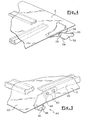
- the roof is again seen in the open position, and it is in particular a front guide rail 30 can be seen, the front ends with a forward and downward inclined and a ramp with a sinusoidal course forming part 31.
- the forward end 32 of said sloped portion is at a lower level relative to the remainder of the rail, but remains within the range of the headliner thickness.
- the rail 30 has a total of a U-shaped, open laterally in the direction of the center of the vehicle cross-section.
- a rear guide rail 50 can be seen, which is also completed in the forward direction by an inclined ramp 51.
- the rear Guide rail as shown relative to the edge of the fixed disc 3 laterally outwardly.
- the sliding shoes are located relative to the pivoting device rod on the outside, which assembly is therefore suitable for the variant in which the rear guide rail is aligned in the direction of the roof edge (case of Fig. 3).
- the shoes are oriented towards the center plane of the vehicle and are thus capable of slidably moving in a manner below the edge of the fixed disc, as shown in Figs.
- the front guide means 40 which are shown in Figures 5, 6 and 8, on both sides of an arm 42 which is secured for example by screws 43 or the like to a bracket 23 formed by an angle plate, said angle plate, for example, by gluing below the movable disc 2 is fixed.
- the arm 42 extends substantially in a vertical longitudinal plane relative to the vehicle down and carries in its lower part a shoe 45 which is rotatably mounted on its axis 46 which is fixedly connected to the arm and extending perpendicular thereto.
- the drive means of the movable disc comprises a drive slide 60 which is slidably mounted on a slide guide rail 61 which extends parallel to the general guide rail 30 on the other side thereof relative to the general plane of the arm 42, as particularly in Fig. 9 see is.
- the drive carriage 60 is in turn driven in translation in a conventional manner by a drive cable 62, which is moved for example by an electric motor and is guided in a provided in the rail 61 suitable groove 63.
- the cable 62 is connected to the carriage 61 by a wedge 64 inserted in the slot 65 provided in the carriage.
- the carriage 60 carries a vertically movable slide block 66 which is guided in a T-shaped slide rail of the carriage, and the slide block has a vertical groove 68 in which a pin 49 engages, which is fixedly connected to the arm 42, the extends horizontally on the side of the arm 45 opposite arm.
- the entirety of the system constituted by said pin, slide block and slide forms a telescopic connection system which makes it possible to ensure a vertical stroke of the arm which is greater than the stroke, which, for example, is due solely to the direct displacement of the pin of the arm a groove made directly in the carriage would be possible.
- the vertical space requirement of the drive means can be reduced, which makes it possible to accommodate them in the thickness of the headliner.
- the arm 42 is moved by the force acting on the shoe 45 second pitch 35 upwards, and the pin 49 arrives in the groove 68 at the top stop. Consequently, in order to be able to continue the movement up to the open position, the pin takes the sliding block upwards and causes it to slide in the T-shaped slide rail 67 of the carriage, allowing the arm 42 to be raised further until the shoe 45 arrives at the level of the horizontal part of the guide rail 30.
- Fig. 20 shows the position of the rear part 21 of the movable disc in the closed position, wherein the disc is supported on the seal 7.
- the rear pivot bar 52 rotates rearwardly in a vertical and longitudinal plane relative to the vehicle and causes the rear edge 21 of the movable disc 2 to lift.
- the two sliding blocks 54, 55 are in the substantially horizontal area As shown in Fig. 21, the rear portion of the disc is in the upper position, and the disc can move further backwards, sliding over the fixed disc 3.
- the pivoting means bars 52 pass on both sides the above the rear guide rail 50 located side edges 39 of the fixed disc. 3
- the embodiment described above in no way limits the invention.
- the invention also applies to the case in which no half-opened intermediate position is provided, in which case the end ramp of the guide rail has no intermediate stage, but a continuous slope.
- the means which ensure the telescopic sliding movement of the arm relative to the drive carriage can be replaced by means of equivalent technology.
- the means of the telescopic connection according to the invention can also be used with other than the above-described rear guide means, without departing from the scope of the invention.
Abstract
Description
Die vorliegende Erfindung bezieht sich auf ein Schiebedach für ein Kraftfahrzeug und insbesondere auf das Führungssystem der beweglichen Scheibe dieses Daches, welches es ermöglicht, seine Öffnung durch ein im wesentlichen horizontales Verschieben zu bewirken.The present invention relates to a sunroof for a motor vehicle and more particularly to the guide system of the movable disc of this roof, which makes it possible to effect its opening by a substantially horizontal displacement.
Es sind bereits zahlreiche Vorrichtungen dieser Art bekannt, sie werden insbesondere in dem Dokument FR-A-2797225 beschrieben. Bei dieser Vorrichtung wird die bewegliche Scheibe, deren allgemeine Form im wesentlichen rechteckig ist, durch einen Satz von Schwenkeinrichtungen oder Klauen getragen, die an den vier Ecken mit ihr verbunden sind und die im übrigen in seitlichen Führungsschienen geführt und verschieblich nach vorwärts und nach rückwärts bewegt werden, was im allgemeinen durch ein durch einen Motor angetriebenes Kabel oder ein anderes äquivalentes Antriebsmittel erfolgt. Die erwähnte bewegliche Scheibe befindet sich im vorderen Teil des Fahrzeuges und öffnet sich, indem sie sich nach hinten und unter ein festes Dachelement bewegt. Um die bewegliche Scheibe in der geschlossenen Position im wesentlichen ohne Überstand relativ zum festen Element und zum Rest des Daches zu halten, wird das Führungssystem in der Weise gestaltet, daß mit Beginn des Öffnungshubs mindestens der rückwärtige Teil der beweglichen Scheibe angehoben wird, damit er sich in einer Position oberhalb des Niveaus der festen Scheibe befindet.Numerous devices of this type are already known, they are described in particular in document FR-A-2797225. In this device, the movable disc, the general shape of which is substantially rectangular, is carried by a set of pivoting devices or jaws connected to it at the four corners and which, moreover, are guided in lateral guide rails and slidably moved forwards and backwards which is generally done by a motor driven cable or other equivalent drive means. The mentioned movable disc is located in the front part of the vehicle and opens by moving backwards and under a fixed roof element. In order to keep the movable disc in the closed position substantially without a projection relative to the fixed element and the rest of the roof, the guide system is designed in such a way that at the beginning of the opening stroke at least the rear part of the movable disc is raised so that he in a position above the level of the fixed disc.
Bei der Vorrichtung nach dem vorgenannten Dokument ermöglicht es das genannte schnelle Anheben des rückwärtigen Teils der beweglichen Scheibe außerdem, eine Zwischenposition der Öffnung zu liefern, bei der die bewegliche Scheibe geneigt ist, wobei die Vorderseite der beweglichen Scheibe in der niedrigen Stellung auf einer vorderen Dichtung abgestützt verbleibt, um Luftzug und Geräuschentwicklung im Fahrzeuginneren zu begrenzen. Wenn die Betätigungsmittel betätigt werden, um die bewegliche Scheibe über ihre geöffnete Stellung hinaus zu bewegen, wird die Vorderseite der beweglichen Scheibe entsprechend angehoben, und die Scheibe kann oberhalb der festen Scheibe nach hinten gleiten.In the device according to the above-mentioned document, said rapid lifting of the rear part of the movable disk also enables an intermediate position of the opening in which the movable disc is inclined, the front of the movable disc remains supported in the low position on a front seal to limit draft and noise inside the vehicle. When the actuators are actuated to move the moveable disc beyond its open position, the front of the moveable disc is correspondingly raised and the disc can slide rearwardly above the fixed disc.
In der Tat weist das System auf jeder Fahrzeugseite eine vordere Schwenkeinrichtungsstange bzw. einen vorderen Arm auf, die jeweils einzeln durch eine Schiene in geeigneter Form geführt werden.In fact, the system has on each side of the vehicle a front pivot bar or arm, each guided individually by a rail in a suitable form.
Die hintere Schwenkeinrichtungsstange ist entsprechend einer zum Fahrzeug in Querrichtung verlaufenden Schwenkachse bzw. Gelenkachse auf einem mit der Scheibe fest verbundenen Schwenkeinrichtungsträger drehbar montiert, so daß sich die Schwenkeinrichtungsstange in einer vertikalen Längsebene dreht. Die Schwenkeinrichtungsstange weist im übrigen in einem Abstand von ihrer Gelenkachse in Richtung auf das Fahrzeugheck zwei Finger auf, die sich im wesentlichen parallel zur genannten Achse erstrecken und die in ein und dieselbe hintere Führungsschiene eingreifen, welche mit dem Fahrzeugdach fest verbunden ist, eine seitlich geöffnete U-förmige Querschnittsform aufweist und sich in Richtung des Fahrzeughecks gesehen in einem seitlichen Bereich neben dem festen Element in der Weise erstreckt, daß eine Führung der Schwenkeinrichtungsstange während des gesamten Öffnungshubs der beweglichen Scheibe sichergestellt wird. In ihrem im Fahrzeug am weitesten vorne gelegenen Teil weist die genannte Schiene eine gekrümmte Form auf, deren konkaver Teil nach unten gerichtet ist, und es liegen, wenn sich das Dach am Ende des Vorwärtshubs in der geschlossenen Stellung befindet, die beiden Finger in diesem gekrümmten Teil, wobei dann der am weitesten vorne liegende Finger tiefer liegt als der weiter hinten liegende. In dieser Schließstellung wird also die Gelenkachse der Schwenkeinrichtungsstange in gewisser Weise nach unten gedrückt, um die bewegliche Scheibe fest auf die peripheren Dichtungen der Dachöffnung zu drücken. Wenn dagegen die Scheibe nach hinten zu gleiten beginnt, bewirken die Finger, indem sie sich gleitend in dem gekrümmten Teil der Schiene bewegen, daß sich die Schwenkeinrichtungsstange dreht und die Gelenkachse nach oben mitnimmt, also demzufolge die hintere Kante der beweglichen Scheibe über das Niveau der festen Scheibe anhebt, wie dies vorstehend angegeben wurde. Bei der Fortsetzung der Bewegung nach hinten gelangen die beiden Finger in einen Teil der Schiene, der im wesentlichen geradlinig und parallel zum Dach verläuft, und gleiten dort bis zum Ende des Hubes nach hinten, wobei sie demzufolge eine Bewegung der beweglichen Scheibe nach hinten sicherstellen, die im wesentlichen parallel zur festen Scheibe erfolgt.The rear pivot arm bar is rotatably mounted on a pivotal support beam fixedly connected to the pulley according to a transverse axis of the vehicle so that the pivot arm shaft rotates in a vertical longitudinal plane. The pivoting device rod has, moreover, at a distance from its axis of articulation in the direction of the rear of the vehicle, two fingers which extend substantially parallel to said axis and which engage in one and the same rear guide rail fixedly connected to the vehicle roof, a laterally open one U-shaped cross-sectional shape and extends in the direction of the vehicle rear in a lateral region adjacent to the fixed element in such a way that a guide of the pivoting device rod is ensured during the entire opening stroke of the movable disk. In its frontmost part of the vehicle, said rail has a curved shape with its concave part directed downwards and, when the roof is in the closed position at the end of the forward stroke, the two are located Fingers in this curved part, in which case the foremost finger is lower than the one furthest back. In this closed position so the hinge axis of the pivoting device rod is pushed down in some ways to press the movable disc firmly on the peripheral seals of the roof opening. If, on the other hand, the disc begins to slide backwards, the fingers, slidingly moving in the curved part of the track, cause the pivot bar to rotate and take the hinge axis upwards, hence the trailing edge of the moving disc above the level of the track fixed disc as stated above. Continuing the rearward movement, the two fingers pass into a portion of the rail which is substantially rectilinear and parallel to the roof, and slide back to the end of the stroke, thus ensuring rearward movement of the movable disk. which takes place substantially parallel to the fixed disk.
Die Führung des vorderen Teils der beweglichen Scheibe wird in analoger Weise durch eine vordere Schwenkeinrichtungsstange ausgeführt, die ebenfalls zwei Finger aufweist, die in ein und derselben vorderen Führungsschiene geführt werden, wobei diese Schiene gelenkig an einem mit der beweglichen Scheibe verbundenen Befestigungspunkt montiert ist. Dagegen ist die Form der Führungsbahn der Schiene in ihrem weiter vorne gelegenen Teil leicht unterschiedlich und weist insbesondere eine leicht sinusförmige Form auf, wobei ein erster Teil wie die gekrümmte Bahn der hinteren Führungsschiene gekrümmt und speziell dafür vorgesehen ist, zu bewirken, daß sich die Vorderkante der beweglichen Scheibe korrekt auf der Dichtung in der halb geöffneten Stellung abstützt, nachdem sie sich vorher während des ersten Öffnungshubs ein wenig von derselben entfernt hatte. Die Bahn weist einen zweiten Teil auf, welcher eine zweite Krümmung aufweist, um die Scheibe für die Fortsetzung ihrer Öffnung anzuheben, und er setzt sich anschließend durch einen geradlinigen Führungsteil bis zur Position der maximalen Öffnung fort.The guide of the front part of the movable disc is carried out in an analogous manner by a front pivot bar, which also has two fingers which are guided in one and the same front guide rail, said rail being pivotally mounted on an attachment point connected to the movable disc. In contrast, the shape of the guideway of the rail is slightly different in its forwardmost part and in particular has a slightly sinusoidal shape, a first part, like the curved track of the rear guide rail, being curved and specially designed to cause the leading edge the movable disk is supported correctly on the gasket in the half-open position after it had been slightly removed from it during the first opening stroke. The web has a second part which has a second curvature around the disk for continuation its opening and then continues through a rectilinear guide member to the position of maximum opening.
Die Verwendung dieses Systems hat jedoch ihre Grenzen, wenn es notwendig ist, einen relativ großen Hub der Vorderkante der beweglichen Scheibe sicherzustellen, was besonders bei Fahrzeugen der Fall sein kann, bei denen insbesondere aus Styling-Gründen der Bereich der Vorderkante der beweglichen Scheibe wesentlich breiter ist als der Rest der Scheibe. Da im übrigen die Gesamtheit der Scheibe in das Dach eingepaßt werden muß, und insbesondere nicht relativ zu den Rändern des Daches oder seitlichen Zierleisten in der Höhe überstehen darf, ist es notwendig, die Scheibe ausreichend anzuheben, um diesen Rändern oder Zierleisten auszuweichen und es zu ermöglichen, daß die vorderen Ränder der Scheibe darüber hinweggleiten, wenn die Scheibe sich nach hinten bewegt. Es ist also erforderlich, daß nicht nur der hintere Teil der beweglichen Scheibe ausreichend angehoben wird, um über die rechte Scheibe hinwegzugleiten, sondern auch, daß der Vorderteil ausreichend angehoben wird, um über die seitlichen Dachränder hinwegzugleiten. Aus Gründen des Platzbedarfs im Dachbereich ist es nun nicht möglich, im vorderen Bereich des Fahrzeuges Systeme wie die vorstehend beschriebenen Schwenkeinrichtungssysteme vorzusehen, die es ermöglichen würden, einen ausreichenden vertikalen Hub der Scheibe sicherzustellen, wobei die Systeme gleichzeitig aus ästhetischen Gründen in der Dicke des Daches kaschiert werden müssen und eine akzeptable Dachstärke einzuhalten ist.However, the use of this system has its limitations when it is necessary to ensure a relatively large stroke of the leading edge of the movable disc, which may be the case especially for vehicles in which, especially for styling reasons, the area of the leading edge of the movable disc much wider is as the rest of the disc. Moreover, since the entirety of the disc must be fitted in the roof, and in particular must not protrude in height relative to the edges of the roof or side trim, it is necessary to raise the disc sufficiently to avoid these edges or trim and it allow the front edges of the disc to slide over it as the disc moves rearward. Thus, it is necessary that not only is the rear portion of the movable disk raised sufficiently to slide over the right disk, but also that the front portion be raised sufficiently to slide over the lateral roof edges. For reasons of space requirements in the roof area, it is now not possible to provide in the front area of the vehicle systems such as the pivoting systems described above, which would make it possible to ensure a sufficient vertical stroke of the disc, the systems at the same time for aesthetic reasons in the thickness of the roof must be concealed and an acceptable roof thickness is observed.
Der Erfindung liegt die Aufgabe zugrunde, diese Probleme zu lösen, und sie betrifft insbesondere die Bereitstellung eines Betätigungs- und Führungssystems der beweglichen Scheibe, das keine Einschränkungen hinsichtlich der äußeren Formen der zu öffnenden Scheibe bewirkt.The invention has for its object to solve these problems, and more particularly relates to the provision of an actuating and guiding system of the movable disk, which causes no restrictions on the outer shapes of the disk to be opened.
Im Hinblick auf diese Aufgaben hat die Erfindung ein Schiebedach für Kraftfahrzeuge zum Gegenstand, welches eine bewegliche Scheibe, die dazu bestimmt ist, eine im Dach vorgesehene Öffnung zu verschließen oder freizugeben, vordere Führungsmittel und hintere Führungsmittel zur Führung einer Öffnungsoder Schließbewegung der beweglichen Scheibe nach einem Hub, dessen allgemeine Richtung im wesentlichen horizontal verläuft und am Ende mit einer geneigten Bahn abschließt, die eine vertikale Bewegung bewirkt, und Antriebsmittel, welche auf die vorderen Führungsmittel einwirken, um die genannte Bewegung jeweils nach vorne und nach hinten zu steuern, aufweist
dadurch gekennzeichnet, daß die vorderen Führungsmittel mit den Antriebsmitteln durch teleskopische Verbindungsmittel verbunden sind, welche die Bewegung der Führungsmittel relativ zu den Antriebsmitteln nach einer im wesentlichen vertikalen Richtung erlauben.In view of these objects, the invention relates to a sliding roof for motor vehicles, which comprises a movable disc, which is intended to close or release an opening provided in the roof, front guide means and rear guide means for guiding an opening or closing movement of the movable disc after a Stroke whose general direction is substantially horizontal and terminates at the end with an inclined path which causes a vertical movement, and drive means which act on the front guide means to control said movement forward and backward, respectively
characterized in that the front guide means are connected to the drive means by telescopic connection means which allow movement of the guide means relative to the drive means in a substantially vertical direction.
Wie im weiteren Verlauf besser zu verstehen sein wird, kann also der Antrieb in an sich bekannter Weise erfolgen, beispielsweise durch ein Antriebskabel, dessen mit den Führungsmitteln verbundenes Ende sich nach einer geradlinigen, im wesentlichen horizontalen Bahn bewegt, wobei es die vertikalen teleskopischen Verbindungsmittel dem Führungsmittel erlauben, eine bedeutende vertikale Bewegung auszuführen, und wobei sie gleichzeitig in der Schließstellung des Schiebedachs einen geringen Platzbedarf haben, der es ermöglicht, die genannten Verbindungsmittel in der Dicke der Dachauskleidung zu kaschieren.As will be better understood in the further course, so the drive can be done in a conventional manner, for example by a drive cable whose end connected to the guide means moves to a rectilinear, substantially horizontal path, wherein the vertical telescopic connecting means the Guide means allow to carry out a significant vertical movement, and at the same time have a small footprint in the closed position of the sliding roof, which makes it possible to conceal said connecting means in the thickness of the roof lining.
Nach einer besonderen Anordnung der Erfindung weisen die Antriebsmittel einen Antriebsschlitten auf, und die teleskopischen Verbindungsmittel weisen einen Gleitblock auf, der in einer vertikalen Gleitbewegung auf dem Antriebsschlitten geführt wird und auf dem die Führungsmittel bei einer vertikalen Gleitbewegung geführt werden.According to a particular arrangement of the invention, the drive means on a drive carriage, and the telescopic connection means comprise a sliding block which in a vertical sliding movement is performed on the drive carriage and on which the guide means are guided in a vertical sliding movement.
Nach einer bevorzugten Ausführungsform wird der Gleitblock auf dem Antriebsschlitten durch ein T- oder schwalbenschwanzförmiges Gleitschienensystem geführt, und die Führungsmittel weisen einen Zapfen auf, der sich seitlich erstreckt und in einer in dem Gleitblock angebrachten Nut geführt wird.According to a preferred embodiment, the sliding block is guided on the drive carriage through a T-shaped or dovetailed sliding rail system, and the guide means comprise a pin which extends laterally and is guided in a groove mounted in the sliding block.
Nach einer weiteren besonders vorteilhaften Anordnung weisen die vorderen Führungsmittel auf jeder Seite der beweglichen Scheibe eine mit dem Dach fest verbundene vordere Führungsschiene auf, in die ein Gleitschuh eingreift, welcher mit einem fest auf der Scheibe befestigten Arm verbunden ist, wobei die Schiene einen seitlich zur Mitte des Fahrzeuges hin offenen U-förmigen Querschnitt hat und in Richtung auf das Fahrzeuginnere relativ zu einer Dichtung montiert ist, die die Öffnung begrenzt und auf die die bewegliche Scheibe in der Schließstellung zu liegen kommt.According to a further particularly advantageous arrangement, the front guide means on each side of the movable disc on a fixed fixed to the roof front guide rail, in which engages a sliding shoe, which is connected to an arm fixedly mounted on the disc, the rail a laterally to Center of the vehicle has open U-shaped cross section and is mounted in the direction of the vehicle interior relative to a seal which limits the opening and on which the movable disc comes to rest in the closed position.
Wenn demzufolge das Dach in der geschlossenen Stellung befindlich ist, liegen sämtliche Führungs- und Antriebsmittel relativ zu den Dichtungen eher im Inneren des Fahrzeuges und werden also vor Witterungs- und sonstigen für die Führungs- und Antriebseinrichtungen schädlichen äußeren Einflüssen vollkommen geschützt. Dank des in der Höhe reduzierten Platzbedarfs, der durch die teleskopischen Verbindungsmittel erhalten wird, können die genannten Führungs- und Antriebsmittel darüber hinaus in der Dicke des Daches untergebracht werden, und sie schaden damit nicht dem ästhetischen Eindruck im Fahrzeuginneren.Accordingly, when the roof is in the closed position, all guiding and driving means are closer to the seals rather in the interior of the vehicle and are therefore completely protected from weather and other harmful to the management and drive equipment external influences. In addition, thanks to the height-reduced space required by the telescopic connecting means, said guiding and driving means can be accommodated in the thickness of the roof, and thus do not harm the aesthetic appearance in the vehicle interior.
Vorzugsweise weisen die Führungsschienen vorne einen Teil auf, der eine geneigte Bahn mit einer Zwischenstufe mit umgekehrter Neigung sicherstellt, um dem Schiebedach eine halbgeöffnete Zwischenstellung zu liefern. Wie dies im weiteren Verlauf erläutert werden wird, gestattet diese Anordnung in der Tat, die Dichtigkeit der Vorderkante der sich öffnenden Scheibe dank der Zwischenstufe der Schiene sicherzustellen, die ein erneutes Abstützen der beweglichen Scheibe auf der Dichtung bewirkt, nachdem sie sich ganz am Anfang der Öffnung davon gelöst hatte, wobei dann die hintere Kante der beweglichen Scheibe bereits in der angehobenen Stellung befindlich ist.Preferably, the guide rails in front on a part of an inclined track with an intermediate stage with the reverse Tilt ensures to provide the sunroof with a semi-open intermediate position. Indeed, as will be explained later, this arrangement allows to ensure the sealing of the front edge of the opening disc, thanks to the intermediary of the rail, which re-supports the movable disc on the seal, after being at the very beginning Opening had solved this, in which case the rear edge of the movable disc is already located in the raised position.
Nach einer weiteren bevorzugten Anordnung weisen die hinteren Führungsmittel auf jeder Seite eine hintere Führungsschiene auf, die mit dem Dach fest verbunden ist und in den Gleitschuh eingreifen, welche fest mit einer drehbar an der Scheibe montierten Schwenkeinrichtungsstange verbunden sind, wobei die Schiene einen seitlich hin zur Außenseite des Fahrzeuges offenen U-förmigen Querschnitt hat und in Richtung auf die Mitte des Fahrzeuges relativ zu einer Dichtung unter einer festen Dachscheibe, auf deren beiden Seiten sich die Schwenkeinrichtungsstangen bewegen, montiert ist.According to a further preferred arrangement, the rear guide means on each side a rear guide rail which is fixedly connected to the roof and engage in the sliding shoe, which are fixedly connected to a rotatably mounted on the disc pivoting device rod, the rail a laterally towards Outside of the vehicle has open U-shaped cross-section and is mounted towards the center of the vehicle relative to a seal under a fixed roof glass, on both sides of the pivoting device rods move.
Diese Anordnung erlaubt es insbesondere, die hinteren Führungsschienen unter der hinter der Dachöffnung angeordneten festen Scheibe, und zwar innerhalb der Dachstärke zu plazieren. Diese Anordnung ermöglicht es entsprechend, die seitlichen Ränder des Daches vollständig von sämtlichen Führungsmitteln zu befreien, wobei diese Ränder dann in sehr viel einfacherer Form ausgestaltet werden können, insbesondere nur die Funktion von Zierleisten erfüllen und keinerlei mechanische Funktion als Schiene oder sonstiges Führungsorgan haben, was zu Einschränkungen hinsichtlich der mechanischen Festigkeit führen würde.This arrangement makes it possible, in particular, to place the rear guide rails under the fixed disc arranged behind the roof opening, namely within the roof thickness. This arrangement accordingly makes it possible to completely rid the lateral edges of the roof of all guide means, which edges can then be configured in a much simpler form, in particular fulfill only the function of moldings and have no mechanical function as a rail or other management body, which would lead to limitations in terms of mechanical strength.
Weitere erfindungswesentliche Merkmale gehen aus der nachfolgenden Beschreibung hervor, in der mit Bezug auf die Zeichnungen Ausführungsbeispiele erläutert werden. In den Zeichnungen zeigen:
- Fig. 1 eine teilweise perspektivische Übersichtsansicht der Oberseite des Fahrzeugschiebedaches in der geschlossenen Stellung;
- Fig. 2 eine analoge Darstellung in der geöffneten Stellung;
- Fig. 3 eine Teilansicht der linken Dachhälfte, wobei die bewegliche Scheibe offen ist, und die die Lage der Führungsmittel der beweglichen Scheibe zeigt;
- Fig. 4 die Verbindung einer hinteren Führungsschwenkeinrichtung an der beweglichen Scheibe;
- Fig. 5 die Verbindung eines vorderen Führungsarmes mit der beweglichen Scheibe;
- Fig. 6 eine Explosionszeichnung des Antriebsschlittens und des vorderen Führungsarmes;
- Fig. 7 eine Explosionszeichnung der hinteren Führungsschwenkeinrichtungsstange und ihrer Verbindung an der beweglichen Scheibe;
- Fig. 8 eine von der Fahrzeuginnenseite her gesehene Seitenansicht der vorderen Führungsmittel, welche das vordere Ende der vorderen Führungsschiene und den vorderen Führungsarm in der geschlossenen Stellung der beweglichen Scheibe zeigt, wobei der Antriebsschlitten nicht gezeigt wird;
- Fig. 9 eine teilweise Schnittansicht nach der Linie IX-IX der Fig. 8 ist;
- Fig. 10 eine Seitenansicht mit der Darstellung der Position des vorderen Führungsarms und des Antriebsschlittens bei geschlossener beweglicher Scheibe;
- Fig. 11 eine Schnittansicht nach der Linie H-H der Fig. 10;
- Fig. 12 eine Schnittansicht nach der Linie I-I der Fig. 10;
- Fig. 13 bis 18 den
Figuren 10, 11, 12 entsprechende Ansichten, jeweils in einer halb geöffneten Stellung der beweglichen Scheibe (Figuren 13 bis 15) und in einer voll geöffneten Stellung (Figuren 16 bis 18); - Fig. 19 eine Seitenansicht der hinteren Führungsmittel in der geschlossenen Stellung, wobei die Schwenkeinrichtungsstange und die bewegliche Scheibe in gestrichelten Linien in der Öffnungsstellung dargestellt werden;
- Fig. 20 eine Schnittansicht nach der Linie 20-20 der Fig. 19, wobei die bewegliche Scheibe geschlossen ist und
- Fig. 21 eine entsprechende weiter nach hinten versetzte Ansicht bei geöffneter beweglicher Scheibe ist.
- Figure 1 is a partial perspective overview of the top of the vehicle sunroof in the closed position.
- Fig. 2 is an analog representation in the open position;
- Fig. 3 is a partial view of the left half of the roof with the movable disc open, showing the position of the movable disc guiding means;
- 4 shows the connection of a rear guide pivoting device to the movable disk;
- Figure 5 shows the connection of a front guide arm with the movable disc.
- Fig. 6 is an exploded view of the drive carriage and the front guide arm;
- Fig. 7 is an exploded view of the rear guide pivot bar and its connection to the movable disk;
- Fig. 8 is a side view, seen from the vehicle interior side, of the front guide means showing the front end of the front guide rail and the front guide arm in the closed position of the movable disk, the drive carriage not being shown;
- Fig. 9 is a partial sectional view taken along the line IX-IX of Fig. 8;
- Fig. 10 is a side view showing the position of the front guide arm and the drive carriage with the movable disk closed;
- Fig. 11 is a sectional view taken along the line HH of Fig. 10;
- Fig. 12 is a sectional view taken along the line II of Fig. 10;
- Figures 13 to 18 are views similar to Figures 10, 11, 12, respectively in a half-open position of the movable disk (Figures 13 to 15) and in a fully open position (Figures 16 to 18);
- Fig. 19 is a side view of the rear guide means in the closed position, showing the pivot bar and the movable disk in dashed lines in the open position;
- Fig. 20 is a sectional view taken along line 20-20 of Fig. 19, wherein the movable disk is closed and
- Fig. 21 is a corresponding further rearwardly offset view with the movable disk open.
In Fig. 1 wird das Dach 1 eines Fahrzeuges dargestellt, das eine vordere bewegliche Scheibe 2 in geschlossener Stellung aufweist und eine feste hintere Scheibe 3, die seitlich durch eine Zierleiste 4 umrahmt werden.In Fig. 1, the
In Fig. 2 ist die bewegliche Scheibe 2 geöffnet, nachdem sie sich oberhalb der festen Scheibe 3 verschieblich nach hinten bewegt hat, und läßt den Rahmen 5 sichtbar werden, der von der Öffnung 6 des Daches begrenzt wird und eine periphere Dichtung 7 aufweist. Es wird bei dieser Figur bemerkt werden, daß im Hinblick auf die Anpassung an die Gesamtlinie des Fahrzeuges und insbesondere um mit der Seitenkante der beweglichen Scheibe der Linie der Dachkante zu folgen, beispielsweise um eine konstante Breite der Zierleiste beizubehalten, die vordere Kante 20 der beweglichen Scheibe breiter ist als der hintere Teil der genannten Scheibe. Daraus resultiert, daß die seitlichen Enden dieser vorderen Kante über die Zierleiste 4 hervorstehen, wenn die genannte bewegliche Scheibe geöffnet ist.In Fig. 2, the
In der Darstellung der Fig. 3 ist das Dach erneut in geöffneter Stellung zu sehen, und es ist insbesondere eine vordere Führungsschiene 30 zu erkennen, die vorne mit einem nach vorne und nach unten geneigten und eine Rampe mit einem sinusförmigen Verlauf bildenden Teil 31 endet. Das vordere Ende 32 des genannten geneigten Teils liegt relativ zum Rest der Schiene auf einem niedrigeren Niveau, bleibt jedoch im Bereich der Stärke des Dachhimmels. Die Schiene 30 hat insgesamt einen U-förmigen, seitlich in Richtung auf die Mitte des Fahrzeuges offenen Querschnitt.In the illustration of Fig. 3, the roof is again seen in the open position, and it is in particular a
Es wird bemerkt werden, daß die Schiene vollständig unterhalb der die Öffnung des Dachs begrenzenden Dichtung 7 liegt, auf die die bewegliche Scheibe in der Schließstellung zu liegen kommt, sich also im Vergleich zu der genannten Dichtung ebenso wie eine Führungsschiene 61 eines Mitnehmerschlittens 60, der im folgenden detaillierter beschrieben wird, eher im Inneren des Fahrzeuges befindet.It will be noted that the rail lies completely below the opening of the roof limiting seal 7, on which the movable disc comes to lie in the closed position, so compared to the said seal as well as a
In Fig. 3 ist durch Transparenz durch die bewegliche Scheibe 2 auch eine hintere Führungsschiene 50 zu sehen, die ebenfalls in der Richtung nach vorne durch eine geneigte Rampe 51 abgeschlossen wird. In der Ansicht der Fig. 3 wird die hintere Führungsschiene als relativ zur Kante der festen Scheibe 3 seitlich nach außen liegend dargestellt. Wie jedoch später insgesamt oder in Verbindung mit den Figuren 20 und 21 zu zeigen sein wird, kann es bevorzugt werden, diese hinteren Führungsschienen unter den Seitenkanten der festen Scheibe anzuordnen, was es ermöglicht, der Kante des Daches die alleinige Funktion als Zierleiste zu belassen, ohne daß dort die für die Plazierung der Schiene notwendigen Ausformungen vorgesehen werden müssen. Unabhängig davon, bleibt die Führungsfunktion der hinteren Seite der beweglichen Scheibe, die im folgenden beschrieben wird, in identischer Weise erhalten.In Fig. 3 by transparency through the
Wie in Fig. 4 dargestellt, weisen die hinteren Führungsmittel der beweglichen Scheibe beiderseits eine Schwenkeinrichtungsstange 52 auf, die drehbar auf einem Zapfen 53 montiert ist, welcher an einer Schwenkeinrichtungslagerung 22 befestigt ist, die unterhalb der beweglichen Scheibe 2, beispielsweise durch Kleben, verbunden wird. Entfernt von diesem Zapfen weist die Schwenkeinrichtungsstange 52 zwei Führungsgleitschuhe 54, 55 auf, die in einer solchen Weise angeordnet sind, daß sie mit der Achse des Zapfens ein Dreieck bilden und die auch in adäquater Form angeordnet sind, um die für den hinteren Teil der beweglichen Scheibe erforderliche, durch die Pfeile der Fig. 19 dargestellte Kinematik zu erhalten. Es wird zur Erinnerung festgehalten, daß der vordere Teil 51 der hinteren Führungsschiene 50 in Form eines Kreisbogens ausgebildet ist, was in Fig. 19 gut zu sehen ist, und daß der Gleitschuh auf der Schwenkeinrichtungsstange liegen, so daß:
- in der geschlossenen Stellung der beweglichen
Scheibe 2 die Interaktion des geneigten Teils 51 der Schiene und der Führungsgleitschuhe 54, 55 die Schwenkeinrichtungsstange 52 in einer in durchgezogenen Linien in Fig. 19 gezeigten, im wesentlichen horizontalen Lage hält, wobei der Zapfen 53 in der unteren Stellung befindlich ist und die bewegliche Scheibe nach unten gegen die Dichtung 7 abgestützt hält; - wenn die Bewegung der beweglichen Scheibe nach hinten gesteuert wird, bewirkt die
Schiene 50, daß der hintere Gleitschuh 55 sich im wesentlichen horizontal gleitend bewegt, während dieNeigung der Rampe 51 der zweite Gleitschuh 54 nach oben bewegt, was zur Wirkung hat, dieSchwenkeinrichtungsstange 52 drehen zu lassen und in die in Fig. 19 in gestrichelter Linie dargestellte Lage zu führen, alsoden hinteren Teil 21 der beweglichen Scheibe anzuheben und gleichzeitig nach oberhalb der festenScheibe 3 zu führen.
- in the closed position of the
movable disk 2, the interaction of theinclined part 51 of the rail and the guide shoes 54, 55 keeps the pivotingdevice rod 52 in a substantially horizontal position shown in solid lines in Fig. 19, thepin 53 in the located lower position and keeps the movable disc supported against the seal 7 down; - When the movement of the movable disc is controlled rearwardly, the
rail 50 causes therear shoe 55 to slide substantially horizontally, while the inclination of theramp 51 of thesecond shoe 54 moves upward, causing thepivot rod 52 to act to rotate and to guide in the position shown in dashed line in Fig. 19, ie to lift therear part 21 of the movable disk and at the same time to lead to above the fixeddisk 3.
Ein System mit einer ähnlichen Kinematik für die Führung des rückwärtigen Teils der beweglichen Scheibe wird in dem bereits zitierten Dokument FR-A-2797225 beschrieben.A system with similar kinematics for guiding the rear part of the movable disk is described in the already cited document FR-A-2797225.
Fig. 7 ist eine Explosionsdarstellung der Schwenkeinrichtungsstange 52, ihrer Lagerung 22 und ihrer Gleitschuhe 55. Es ist hier anzumerken, daß die Gleitschuhe relativ zur Schwenkeinrichtungsstange auf der Außenseite gelegen sind, wobei diese Montage also für die Variante geeignet ist, bei der die hintere Führungsschiene in Richtung auf die Dachkante ausgerichtet ist (Fall der Fig. 3). Im Gegensatz dazu sind.im Fall der Fig. 4 die Gleitschuhe zur Mittelebene des Fahrzeuges hin orientiert und also geeignet, sich, wie in den Figuren 20 und 21 gezeigt, in einer unterhalb der Kante der festen Scheibe gleitend zu bewegen.It is to be noted here that the sliding shoes are located relative to the pivoting device rod on the outside, which assembly is therefore suitable for the variant in which the rear guide rail is aligned in the direction of the roof edge (case of Fig. 3). In contrast, in the case of Fig. 4, the shoes are oriented towards the center plane of the vehicle and are thus capable of slidably moving in a manner below the edge of the fixed disc, as shown in Figs.
Die vorderen Führungsmittel 40, die in den Figuren 5, 6 und 8 dargestellt werden, weisen beiderseits einen Arm 42 auf, der beispielsweise durch Schrauben 43 oder ähnliches an einer durch ein Winkelblech gebildete Lagerung 23 befestigt ist, wobei das genannte Winkelblech beispielsweise durch Klebung unterhalb der beweglichen Scheibe 2 befestigt ist. Der Arm 42 erstreckt sich im wesentlichen in einer relativ zum Fahrzeug vertikalen Längsebene nach unten und trägt in seinem unteren Teil einen Gleitschuh 45, die drehbar auf ihrer Achse 46 montiert ist, welche fest mit dem Arm verbunden ist und sich senkrecht zu diesem erstreckt.The front guide means 40, which are shown in Figures 5, 6 and 8, on both sides of an
Der Gleitschuh 46 ist geeignet, sich gleitend in der Schiene 30 zu bewegen, deren vorderer Teil die geneigte Rampe 31 bildet, welche gut in Fig. 8 sichtbar ist, wo die dargestellte Schiene die auf der rechten Seite des Fahrzeuges liegende ist. Diese Rampe weist auf:
- einen kurzen horizontalen Abschlußteil 32, der am weitesten unten liegt und in
dem der Gleitschuh 45 untergebracht ist, wenn sich das Dach in der geschlossenen Stellung befindet, wobei die beweglicheScheibe 2 am Ende des Hubs nach vorne befindlich ist; - eine erste
Rampe 33, die dazu bestimmt ist, ein rasches Anheben der beweglichen Scheibe schon am Anfang ihres Hubes nach hinten zu bewirken, insbesondere um die Abstützung der beweglichen Scheibe auf der vorderen Dichtung 71 aufzuheben; eine Zwischenstufe 34, die leicht umgekehrt geneigt und dazu bestimmt ist, ein erneutes Absinken des vorderen Teils der beweglichen Scheibe zu bewirken, um sie erneut auf die Dichtung 7 aufzulegen, wenn aufgrund des Beginns der Verschiebebewegung der Scheibe der hintere Teil 21 derselben sich wie vorstehend in Verbindung mit Fig. 19 angegeben angehoben hat, um die bewegliche Scheibe in eine halb geöffnete Stellung zu bringen, bei der der hintere Teil angehoben und der Vorderteil in abdichtender Form auf dem Vorderteil der Dichtung aufgesetzt bleibt,- eine zweite
Rampe 35, um den Gleitschuh in die obere mit dem im wesentlichen horizontalen Teil der Schiene 30 fluchtende Lage zu bringen, um anschließend die Führung der beweglichen Scheibe bis in ihre Stellung der vollständigen Öffnung zu bringen.
- a short
horizontal end portion 32 located lowermost and in which theshoe 45 is housed when the roof is in the closed position, themovable disk 2 being located forward at the end of the stroke; - a
first ramp 33 which is intended to cause a rapid lifting of the movable disc at the beginning of its stroke to the rear, in particular to cancel the support of the movable disc on thefront seal 71; - an
intermediate stage 34 inclined slightly in reverse and intended to cause the front part of the movable disk to fall again to rest on the seal 7 when, due to the start of the sliding movement of the disk, therear part 21 thereof is as above 19 raised in order to bring the movable disc in a half-open position, in which the rear part is raised and the front part remains in sealing form on the front part of the seal, - a
second ramp 35 for bringing the shoe into the upper position aligned with the substantially horizontal portion of therail 30 to subsequently bring the guide of the movable disk to its full opening position.
Die Antriebsmittel der beweglichen Scheibe weisen einen Antriebsschlitten 60 auf, der gleitend beweglich auf einer Schlittenführungsschiene 61 montiert ist, die sich relativ zur allgemeinen Ebene des Arms 42 parallel zur vorderen Führungsschiene 30 auf der anderen Seite desselben erstreckt, wie dies insbesondere in Fig. 9 zu sehen ist. Der Antriebsschlitten 60 wird seinerseits in der Translation in an sich bekannter Weise durch ein Antriebskabel 62 angetrieben, das beispielsweise durch einen Elektromotor bewegt wird und in einer in der Schiene 61 vorgesehenen geeigneten Nut 63 geführt wird. Das Kabel 62 ist durch einen in der im Schlitten vorgesehenen Spalte 65 eingesetzten Keil 64 mit dem Schlitten 61 verbunden.The drive means of the movable disc comprises a
Der Schlitten 60 trägt einen vertikal beweglichen Gleitblock 66, der in einer T-förmigen Gleitschiene des Schlittens geführt wird, und der Gleitblock weist eine vertikale Nut 68 auf, in die ein Zapfen 49 eingreift, welcher fest mit dem Arm 42 verbunden ist, der sich horizontal auf der Seite des dem Gleitschuh 45 gegenüberliegenden Arms erstreckt. Die Gesamtheit des durch den genannten Zapfen, den Gleitblock und den Schlitten gebildeten Systems bildet ein teleskopisches Verbindungssystem, das es ermöglicht, einen vertikalen Hub des Arms sicherzustellen, der größer ist als der Hub, der beispielsweise allein aufgrund des direkten Verschiebens des Zapfens des Arms in einer direkt in dem Schlitten ausgeführten Rille möglich wäre. Mit anderen Worten kann für eine vorbestimmte Gesamthubhöhe der beweglichen Scheibe 2, die beispielsweise bei dem vorstehenden in Verbindung mit Fig. 2 angegebenen Ausführungsbeispiel erforderlich ist, der vertikale Platzbedarf der Antriebsmittel reduziert werden, was es ermöglicht, sie in der Dicke des Dachhimmels unterzubringen.The
Unter Bezugnahme auf die Figuren 10 bis 18 wird nun die Funktionsweise des erfindungsgemäßen teleskopischen Verbindungssystems beschrieben.The operation of the telescopic connection system according to the invention will now be described with reference to FIGS.
In der in den Figuren 10, 11 und 12 dargestellten Lage ist die bewegliche Scheibe geschlossen, also an ihrer vorderen Anschlagstellung und in der tiefsten Lage befindlich, wobei der Gleitschuh 45 sich in dem Bereich des Endes 32 der Schiene bewegt. Der Zapfen 49 befindet sich also ganz unten in der Nut 68 des Gleitblocks 66, und letzterer ist seinerseits in der tiefstmöglichen Stellung relativ zum Antriebsschlitten 60.In the position shown in Figures 10, 11 and 12, the movable disc is closed, that is, at its front stop position and in the lowest position, wherein the sliding
Wenn das Antriebskabel 62 den Schlitten 60 nach hinten verschiebt, wird diese Bewegung auf den Gleitblock 66 und von dort auf den Zapfen 49 übertragen, der also die Bewegung des Arms 42 und der beweglichen Scheibe 2 bewirkt, wobei der Gleitschuh 45 sich gleitend in der Rampe 31 der vorderen Führungsschiene bewegt.When the
Wenn der Gleitschuh 45 bei der ersten Steigung 33 der Rampe eintrifft, zwingt sie den Arm, sich nach oben zu bewegen, und der Zapfen 49 bewegt sich dann gleitend in der Nut 68 des Gleitblocks 66 nach oben. Bei einer Fortsetzung der Bewegung nach hinten führt der Schlitten somit den Arm 42 bis in die in den Figuren 13 bis 15 dargestellte, halb geöffnete Stellung, in der der Gleitschuh 45 in der Zwischenstufe 34 der Führungsschiene zurückgekehrt ist. Es ist zu sehen, daß der Arm 42 sich ebenso wie der Zapfen 49 in der Nut 68 nach oben bewegt hat, doch der Gleitblock 66 verbleibt relativ zum Schlitten 60 auf der gleichen Höhe.When the
Bei der weiteren Fortsetzung der Bewegung des Schlittens wird der Arm 42 durch die auf den Gleitschuh 45 wirkende zweite Steigung 35 nach oben bewegt, und der Zapfen 49 kommt in der Nut 68 beim oberen Anschlag an. Um die Bewegung bis zur Öffnungsstellung fortsetzen zu können, nimmt demzufolge der Zapfen den Gleitblock nach oben mit und bewirkt, daß er sich in der T-förmigen Gleitschiene 67 des Schlittens gleitend bewegt, was es dem Arm 42 ermöglicht, weiter angehoben zu werden, bis der Gleitschuh 45 auf der Höhe des horizontalen Teils der Führungsschiene 30 eintrifft.In the further continuation of the movement of the carriage, the
Der Antrieb des Schlittens 60 nach hinten kann dann fortgesetzt werden, wobei der Gleitblock in der oberen Stellung verbleibt und der Zapfen ebenfalls in der oberen Stellung in der Nut verbleibt, wie dies in den Figuren 16 bis 18 dargestellt wird.The drive of the
Fig. 20 zeigt die Lage des hinteren Teils 21 der beweglichen Scheibe in der Schließstellung, wobei die Scheibe sich auf die Dichtung 7 abstützt.Fig. 20 shows the position of the
Wie bereits erläutert, dreht sich die hintere Schwenkeinrichtungsstange 52 am Beginn des Hubs nach hinten in einer vertikalen und Längsebene relativ zum Fahrzeug und bewirkt das Anheben der hinteren Kante 21 der beweglichen Scheibe 2. Wenn die beiden Gleitschuhe 54, 55 in dem im wesentlichen horizontalen Bereich der Schiene 50 befindlich sind, befindet sich der hintere Teil der Scheibe, wie in Fig. 21 dargestellt, in der oberen Lage, und die Scheibe kann sich weiter nach hinten bewegen und gleitet dabei über die feste Scheibe 3. Dabei passieren die Schwenkeinrichtungsstangen 52 beiderseits die oberhalb der hinteren Führungsschiene 50 gelegenen Seitenkanten 39 der festen Scheibe 3.As previously discussed, at the beginning of the stroke, the
Das vorstehend beschriebene Ausführungsbeispiel schränkt in keiner Weise die Erfindung ein. Insbesondere findet die Erfindung auch Anwendung für den Fall, bei dem keine halb geöffnete Zwischenstellung vorgesehen ist, wobei dann die Endrampe der Führungsschiene keine Zwischenstufe aufweist, sondern eine kontinuierliche Neigung. Des weiteren können die Mittel, die die teleskopische Gleitbewegung des Arms relativ zum Antriebsschlitten sicherstellen, durch Mittel äquivalenter Technologie ersetzt werden. Die erfindungsgemäßen Mittel der teleskopischen Verbindung können auch mit anderen als den vorstehend beschriebenen hinteren Führungsmitteln verwendet werden, ohne damit den Rahmen der Erfindung zu verlassen.The embodiment described above in no way limits the invention. In particular, the invention also applies to the case in which no half-opened intermediate position is provided, in which case the end ramp of the guide rail has no intermediate stage, but a continuous slope. Furthermore, the means which ensure the telescopic sliding movement of the arm relative to the drive carriage can be replaced by means of equivalent technology. The means of the telescopic connection according to the invention can also be used with other than the above-described rear guide means, without departing from the scope of the invention.
Claims (8)
dadurch gekennzeichnet, daß die vorderen Führungsmittel (40) mit den Antriebsmitteln (60) durch teleskopische Verbindungsmittel (49, 68, 66, 67) verbunden sind, welche die Bewegung der Führungsmittel relativ zu den Antriebsmitteln nach einer im wesentlichen vertikalen Richtung erlauben.Sliding roof for a motor vehicle, comprising a movable disc (2) intended to close or release an opening (6) provided in the roof, front guiding means (40, 30, 31) and rear guiding means (50, 51, 52) ) for guiding an opening or closing movement of the movable disk after a stroke whose general direction is substantially horizontal and terminates at the end with an inclined path which causes a vertical movement, and drive means (60, 49) acting on the front guide means acting to control said movement forward and backward respectively,
characterized in that the front guide means (40) are connected to the drive means (60) by telescopic connection means (49, 68, 66, 67) which allow movement of the guide means relative to the drive means in a substantially vertical direction.
Applications Claiming Priority (2)
| Application Number | Priority Date | Filing Date | Title |
|---|---|---|---|
| FR0212038A FR2845037B1 (en) | 2002-09-27 | 2002-09-27 | SUNROOF FOR MOTOR VEHICLE |
| FR0212038 | 2002-09-27 |
Publications (2)
| Publication Number | Publication Date |
|---|---|
| EP1403113A1 true EP1403113A1 (en) | 2004-03-31 |
| EP1403113B1 EP1403113B1 (en) | 2010-06-09 |
Family
ID=31971030
Family Applications (1)
| Application Number | Title | Priority Date | Filing Date |
|---|---|---|---|
| EP20030020186 Expired - Lifetime EP1403113B1 (en) | 2002-09-27 | 2003-09-05 | Sliding roof for a motor vehicle |
Country Status (3)
| Country | Link |
|---|---|
| EP (1) | EP1403113B1 (en) |
| DE (1) | DE50312791D1 (en) |
| FR (1) | FR2845037B1 (en) |
Cited By (5)
| Publication number | Priority date | Publication date | Assignee | Title |
|---|---|---|---|---|
| EP1859980A1 (en) * | 2006-05-23 | 2007-11-28 | FIAT AUTO S.p.A. | Motor vehicle roof provided with a sunroof panel |
| WO2008017294A1 (en) * | 2006-08-11 | 2008-02-14 | Webasto Ag | Vehicle roof which can be opened and has a modular displacement and guide arrangement |
| WO2011003617A1 (en) * | 2009-07-10 | 2011-01-13 | Webasto Ag | Sliding roof device, in particular for a motor vehicle |
| CN107323232A (en) * | 2017-08-04 | 2017-11-07 | 武汉凯沃森工业科技有限公司 | Warp mechanism kinematic assembly after a kind of vehicle dormer window |
| EP2694306B2 (en) † | 2011-04-04 | 2021-02-24 | Advanced Comfort Systems France SAS - ACS France | Glass roof having a sliding and tilting mobile panel |
Families Citing this family (1)
| Publication number | Priority date | Publication date | Assignee | Title |
|---|---|---|---|---|
| FR2969539B1 (en) * | 2010-12-23 | 2013-01-11 | Webasto Systemes Carrosserie | SLIDING ROOF FOR A MOTOR VEHICLE |
Citations (3)
| Publication number | Priority date | Publication date | Assignee | Title |
|---|---|---|---|---|
| US5069501A (en) * | 1990-08-03 | 1991-12-03 | General Motors Corporation | Spoiler sunroof control mechanism |
| US5197779A (en) * | 1989-06-27 | 1993-03-30 | Mazda Motor Corporation | Power sliding sunroof |
| FR2797225A1 (en) | 1999-08-02 | 2001-02-09 | Webasto Systemes Carrosserie | DEVICE FOR OPENING OR CLOSING A MOVABLE EXTERIOR PANEL OF A TILTING AND SLIDING SUNROOF |
-
2002
- 2002-09-27 FR FR0212038A patent/FR2845037B1/en not_active Expired - Fee Related
-
2003
- 2003-09-05 EP EP20030020186 patent/EP1403113B1/en not_active Expired - Lifetime
- 2003-09-05 DE DE50312791T patent/DE50312791D1/en not_active Expired - Lifetime
Patent Citations (3)
| Publication number | Priority date | Publication date | Assignee | Title |
|---|---|---|---|---|
| US5197779A (en) * | 1989-06-27 | 1993-03-30 | Mazda Motor Corporation | Power sliding sunroof |
| US5069501A (en) * | 1990-08-03 | 1991-12-03 | General Motors Corporation | Spoiler sunroof control mechanism |
| FR2797225A1 (en) | 1999-08-02 | 2001-02-09 | Webasto Systemes Carrosserie | DEVICE FOR OPENING OR CLOSING A MOVABLE EXTERIOR PANEL OF A TILTING AND SLIDING SUNROOF |
Cited By (12)
| Publication number | Priority date | Publication date | Assignee | Title |
|---|---|---|---|---|
| EP1859980A1 (en) * | 2006-05-23 | 2007-11-28 | FIAT AUTO S.p.A. | Motor vehicle roof provided with a sunroof panel |
| WO2008017294A1 (en) * | 2006-08-11 | 2008-02-14 | Webasto Ag | Vehicle roof which can be opened and has a modular displacement and guide arrangement |
| WO2011003617A1 (en) * | 2009-07-10 | 2011-01-13 | Webasto Ag | Sliding roof device, in particular for a motor vehicle |
| FR2947765A1 (en) * | 2009-07-10 | 2011-01-14 | Webasto Systeme Carrosserie | ROOF DEVICE OPENING IN PARTICULAR FOR MOTOR VEHICLE |
| CN102470737A (en) * | 2009-07-10 | 2012-05-23 | 韦巴斯托股份公司 | Sliding roof device, in particular for a motor vehicle |
| JP2012532064A (en) * | 2009-07-10 | 2012-12-13 | ヴェバスト ソシエタス エウロペア | A sliding roof device especially for automobiles |
| US8523278B2 (en) | 2009-07-10 | 2013-09-03 | Webasto SE | Sliding roof device, in particular for a motor vehicle |
| RU2497694C2 (en) * | 2009-07-10 | 2013-11-10 | Вебасто Аг | Car sliding roof |
| CN102470737B (en) * | 2009-07-10 | 2014-07-09 | 韦巴斯托股份公司 | Sliding roof device, in particular for a motor vehicle |
| EP2694306B2 (en) † | 2011-04-04 | 2021-02-24 | Advanced Comfort Systems France SAS - ACS France | Glass roof having a sliding and tilting mobile panel |
| CN107323232A (en) * | 2017-08-04 | 2017-11-07 | 武汉凯沃森工业科技有限公司 | Warp mechanism kinematic assembly after a kind of vehicle dormer window |
| CN107323232B (en) * | 2017-08-04 | 2023-08-29 | 武汉凯沃森工业科技有限公司 | Automobile skylight rear tilting mechanism movement assembly |
Also Published As
| Publication number | Publication date |
|---|---|
| DE50312791D1 (en) | 2010-07-22 |
| EP1403113B1 (en) | 2010-06-09 |
| FR2845037A1 (en) | 2004-04-02 |
| FR2845037B1 (en) | 2004-12-03 |
Similar Documents
| Publication | Publication Date | Title |
|---|---|---|
| DE102005007031B4 (en) | Vehicle roof with a sliding above the roof roof part | |
| DE102006002064B4 (en) | Vehicle roof with a sliding above a fixed roof section lid | |
| DE3442631A1 (en) | SLIDING LIFTING ROOF | |
| DE3444593A1 (en) | LOWERING DEVICE FOR THE REAR WINDOW OF VEHICLES | |
| DE19700165C2 (en) | Sliding lifting roof | |
| DE3146697A1 (en) | VEHICLE SUNROOF | |
| EP1834820A1 (en) | Panoramic roof | |
| EP1922220B1 (en) | Vehicle roof with at least two cover elements | |
| EP0720927B1 (en) | Vehicle roof provided with a roof panel opened by tilting | |
| EP1125778A2 (en) | Open roof construction for vehicle | |
| DE102006051109B4 (en) | Vehicle roof with a movable roof part | |
| DE10158174B4 (en) | Sunroof for vehicles | |
| DE3316739A1 (en) | Motor vehicle roof | |
| DE10082186B4 (en) | Sunroof cover for a roof opening of a vehicle roof | |
| EP1403113B1 (en) | Sliding roof for a motor vehicle | |
| DE19542884C1 (en) | Vehicle roof with extensible slats | |
| DE3129900A1 (en) | Tilt-and-slide sunroof for motor vehicles | |
| DE60221716T2 (en) | ROOF ARRANGEMENT FOR ONE VEHICLE | |
| EP0734895A1 (en) | Vehicle roof | |
| DE10246753B4 (en) | vehicle roof | |
| DE10257673B4 (en) | Closure device provided in the body of a vehicle opening, and corresponding vehicle | |
| DE19654558C2 (en) | sunroof | |
| EP1454783A1 (en) | Vehicle roof with a serie of lamellar plates | |
| DE102005059274B4 (en) | Facing device for vehicle roof systems with openable lid | |
| EP0551840B1 (en) | Sliding sunroof for motorvehicle |
Legal Events
| Date | Code | Title | Description |
|---|---|---|---|
| PUAI | Public reference made under article 153(3) epc to a published international application that has entered the european phase |
Free format text: ORIGINAL CODE: 0009012 |
|
| AK | Designated contracting states |
Kind code of ref document: A1 Designated state(s): AT BE BG CH CY CZ DE DK EE ES FI FR GB GR HU IE IT LI LU MC NL PT RO SE SI SK TR |
|
| AX | Request for extension of the european patent |
Extension state: AL LT LV MK |
|
| 17P | Request for examination filed |
Effective date: 20040423 |
|
| AKX | Designation fees paid |
Designated state(s): DE GB NL |
|
| RAP1 | Party data changed (applicant data changed or rights of an application transferred) |
Owner name: WEBASTO AG |
|
| GRAP | Despatch of communication of intention to grant a patent |
Free format text: ORIGINAL CODE: EPIDOSNIGR1 |
|
| GRAS | Grant fee paid |
Free format text: ORIGINAL CODE: EPIDOSNIGR3 |
|
| GRAA | (expected) grant |
Free format text: ORIGINAL CODE: 0009210 |
|
| AK | Designated contracting states |
Kind code of ref document: B1 Designated state(s): DE GB NL |
|
| REG | Reference to a national code |
Ref country code: NL Ref legal event code: T3 |
|
| REF | Corresponds to: |
Ref document number: 50312791 Country of ref document: DE Date of ref document: 20100722 Kind code of ref document: P |
|
| PLBE | No opposition filed within time limit |
Free format text: ORIGINAL CODE: 0009261 |
|
| STAA | Information on the status of an ep patent application or granted ep patent |
Free format text: STATUS: NO OPPOSITION FILED WITHIN TIME LIMIT |
|
| 26N | No opposition filed |
Effective date: 20110310 |
|
| REG | Reference to a national code |
Ref country code: DE Ref legal event code: R097 Ref document number: 50312791 Country of ref document: DE Effective date: 20110309 |
|
| PGFP | Annual fee paid to national office [announced via postgrant information from national office to epo] |
Ref country code: NL Payment date: 20210921 Year of fee payment: 19 |
|
| PGFP | Annual fee paid to national office [announced via postgrant information from national office to epo] |
Ref country code: DE Payment date: 20210921 Year of fee payment: 19 Ref country code: GB Payment date: 20210923 Year of fee payment: 19 |
|
| REG | Reference to a national code |
Ref country code: DE Ref legal event code: R119 Ref document number: 50312791 Country of ref document: DE |
|
| REG | Reference to a national code |
Ref country code: NL Ref legal event code: MM Effective date: 20221001 |
|
| GBPC | Gb: european patent ceased through non-payment of renewal fee |
Effective date: 20220905 |
|
| PG25 | Lapsed in a contracting state [announced via postgrant information from national office to epo] |
Ref country code: NL Free format text: LAPSE BECAUSE OF NON-PAYMENT OF DUE FEES Effective date: 20221001 |
|
| PG25 | Lapsed in a contracting state [announced via postgrant information from national office to epo] |
Ref country code: DE Free format text: LAPSE BECAUSE OF NON-PAYMENT OF DUE FEES Effective date: 20230401 |
|
| PG25 | Lapsed in a contracting state [announced via postgrant information from national office to epo] |
Ref country code: GB Free format text: LAPSE BECAUSE OF NON-PAYMENT OF DUE FEES Effective date: 20220905 |