EP1403580A1 - Light projector - Google Patents
Light projector Download PDFInfo
- Publication number
- EP1403580A1 EP1403580A1 EP02771762A EP02771762A EP1403580A1 EP 1403580 A1 EP1403580 A1 EP 1403580A1 EP 02771762 A EP02771762 A EP 02771762A EP 02771762 A EP02771762 A EP 02771762A EP 1403580 A1 EP1403580 A1 EP 1403580A1
- Authority
- EP
- European Patent Office
- Prior art keywords
- balloon
- frame body
- light
- column
- light projector
- Prior art date
- Legal status (The legal status is an assumption and is not a legal conclusion. Google has not performed a legal analysis and makes no representation as to the accuracy of the status listed.)
- Granted
Links
Images


Classifications
-
- F—MECHANICAL ENGINEERING; LIGHTING; HEATING; WEAPONS; BLASTING
- F21—LIGHTING
- F21L—LIGHTING DEVICES OR SYSTEMS THEREOF, BEING PORTABLE OR SPECIALLY ADAPTED FOR TRANSPORTATION
- F21L14/00—Electric lighting devices without a self-contained power source, e.g. for mains connection
- F21L14/04—Electric lighting devices without a self-contained power source, e.g. for mains connection carried on wheeled supports
-
- F—MECHANICAL ENGINEERING; LIGHTING; HEATING; WEAPONS; BLASTING
- F21—LIGHTING
- F21S—NON-PORTABLE LIGHTING DEVICES; SYSTEMS THEREOF; VEHICLE LIGHTING DEVICES SPECIALLY ADAPTED FOR VEHICLE EXTERIORS
- F21S8/00—Lighting devices intended for fixed installation
-
- B—PERFORMING OPERATIONS; TRANSPORTING
- B60—VEHICLES IN GENERAL
- B60P—VEHICLES ADAPTED FOR LOAD TRANSPORTATION OR TO TRANSPORT, TO CARRY, OR TO COMPRISE SPECIAL LOADS OR OBJECTS
- B60P3/00—Vehicles adapted to transport, to carry or to comprise special loads or objects
- B60P3/18—Vehicles adapted to transport, to carry or to comprise special loads or objects the object being a searchlight
-
- F—MECHANICAL ENGINEERING; LIGHTING; HEATING; WEAPONS; BLASTING
- F21—LIGHTING
- F21S—NON-PORTABLE LIGHTING DEVICES; SYSTEMS THEREOF; VEHICLE LIGHTING DEVICES SPECIALLY ADAPTED FOR VEHICLE EXTERIORS
- F21S9/00—Lighting devices with a built-in power supply; Systems employing lighting devices with a built-in power supply
- F21S9/04—Lighting devices with a built-in power supply; Systems employing lighting devices with a built-in power supply the power supply being a generator
-
- F—MECHANICAL ENGINEERING; LIGHTING; HEATING; WEAPONS; BLASTING
- F21—LIGHTING
- F21V—FUNCTIONAL FEATURES OR DETAILS OF LIGHTING DEVICES OR SYSTEMS THEREOF; STRUCTURAL COMBINATIONS OF LIGHTING DEVICES WITH OTHER ARTICLES, NOT OTHERWISE PROVIDED FOR
- F21V11/00—Screens not covered by groups F21V1/00, F21V3/00, F21V7/00 or F21V9/00
- F21V11/02—Screens not covered by groups F21V1/00, F21V3/00, F21V7/00 or F21V9/00 using parallel laminae or strips, e.g. of Venetian-blind type
- F21V11/04—Screens not covered by groups F21V1/00, F21V3/00, F21V7/00 or F21V9/00 using parallel laminae or strips, e.g. of Venetian-blind type adjustable
-
- F—MECHANICAL ENGINEERING; LIGHTING; HEATING; WEAPONS; BLASTING
- F21—LIGHTING
- F21V—FUNCTIONAL FEATURES OR DETAILS OF LIGHTING DEVICES OR SYSTEMS THEREOF; STRUCTURAL COMBINATIONS OF LIGHTING DEVICES WITH OTHER ARTICLES, NOT OTHERWISE PROVIDED FOR
- F21V11/00—Screens not covered by groups F21V1/00, F21V3/00, F21V7/00 or F21V9/00
- F21V11/16—Screens not covered by groups F21V1/00, F21V3/00, F21V7/00 or F21V9/00 using sheets without apertures, e.g. fixed
- F21V11/18—Screens not covered by groups F21V1/00, F21V3/00, F21V7/00 or F21V9/00 using sheets without apertures, e.g. fixed movable, e.g. flaps, slides
-
- F—MECHANICAL ENGINEERING; LIGHTING; HEATING; WEAPONS; BLASTING
- F21—LIGHTING
- F21V—FUNCTIONAL FEATURES OR DETAILS OF LIGHTING DEVICES OR SYSTEMS THEREOF; STRUCTURAL COMBINATIONS OF LIGHTING DEVICES WITH OTHER ARTICLES, NOT OTHERWISE PROVIDED FOR
- F21V17/00—Fastening of component parts of lighting devices, e.g. shades, globes, refractors, reflectors, filters, screens, grids or protective cages
- F21V17/10—Fastening of component parts of lighting devices, e.g. shades, globes, refractors, reflectors, filters, screens, grids or protective cages characterised by specific fastening means or way of fastening
- F21V17/16—Fastening of component parts of lighting devices, e.g. shades, globes, refractors, reflectors, filters, screens, grids or protective cages characterised by specific fastening means or way of fastening by deformation of parts; Snap action mounting
- F21V17/164—Fastening of component parts of lighting devices, e.g. shades, globes, refractors, reflectors, filters, screens, grids or protective cages characterised by specific fastening means or way of fastening by deformation of parts; Snap action mounting the parts being subjected to bending, e.g. snap joints
-
- F—MECHANICAL ENGINEERING; LIGHTING; HEATING; WEAPONS; BLASTING
- F21—LIGHTING
- F21V—FUNCTIONAL FEATURES OR DETAILS OF LIGHTING DEVICES OR SYSTEMS THEREOF; STRUCTURAL COMBINATIONS OF LIGHTING DEVICES WITH OTHER ARTICLES, NOT OTHERWISE PROVIDED FOR
- F21V19/00—Fastening of light sources or lamp holders
- F21V19/006—Fastening of light sources or lamp holders of point-like light sources, e.g. incandescent or halogen lamps, with screw-threaded or bayonet base
- F21V19/007—Fastening of light sources or lamp holders of point-like light sources, e.g. incandescent or halogen lamps, with screw-threaded or bayonet base the support means engaging the vessel of the source
-
- F—MECHANICAL ENGINEERING; LIGHTING; HEATING; WEAPONS; BLASTING
- F21—LIGHTING
- F21V—FUNCTIONAL FEATURES OR DETAILS OF LIGHTING DEVICES OR SYSTEMS THEREOF; STRUCTURAL COMBINATIONS OF LIGHTING DEVICES WITH OTHER ARTICLES, NOT OTHERWISE PROVIDED FOR
- F21V21/00—Supporting, suspending, or attaching arrangements for lighting devices; Hand grips
- F21V21/08—Devices for easy attachment to any desired place, e.g. clip, clamp, magnet
- F21V21/0808—Adhesive means
-
- F—MECHANICAL ENGINEERING; LIGHTING; HEATING; WEAPONS; BLASTING
- F21—LIGHTING
- F21V—FUNCTIONAL FEATURES OR DETAILS OF LIGHTING DEVICES OR SYSTEMS THEREOF; STRUCTURAL COMBINATIONS OF LIGHTING DEVICES WITH OTHER ARTICLES, NOT OTHERWISE PROVIDED FOR
- F21V21/00—Supporting, suspending, or attaching arrangements for lighting devices; Hand grips
- F21V21/14—Adjustable mountings
- F21V21/22—Adjustable mountings telescopic
-
- F—MECHANICAL ENGINEERING; LIGHTING; HEATING; WEAPONS; BLASTING
- F21—LIGHTING
- F21V—FUNCTIONAL FEATURES OR DETAILS OF LIGHTING DEVICES OR SYSTEMS THEREOF; STRUCTURAL COMBINATIONS OF LIGHTING DEVICES WITH OTHER ARTICLES, NOT OTHERWISE PROVIDED FOR
- F21V3/00—Globes; Bowls; Cover glasses
- F21V3/02—Globes; Bowls; Cover glasses characterised by the shape
- F21V3/023—Chinese lanterns; Balloons
-
- F—MECHANICAL ENGINEERING; LIGHTING; HEATING; WEAPONS; BLASTING
- F21—LIGHTING
- F21V—FUNCTIONAL FEATURES OR DETAILS OF LIGHTING DEVICES OR SYSTEMS THEREOF; STRUCTURAL COMBINATIONS OF LIGHTING DEVICES WITH OTHER ARTICLES, NOT OTHERWISE PROVIDED FOR
- F21V15/00—Protecting lighting devices from damage
- F21V15/02—Cages
-
- F—MECHANICAL ENGINEERING; LIGHTING; HEATING; WEAPONS; BLASTING
- F21—LIGHTING
- F21V—FUNCTIONAL FEATURES OR DETAILS OF LIGHTING DEVICES OR SYSTEMS THEREOF; STRUCTURAL COMBINATIONS OF LIGHTING DEVICES WITH OTHER ARTICLES, NOT OTHERWISE PROVIDED FOR
- F21V19/00—Fastening of light sources or lamp holders
- F21V19/04—Fastening of light sources or lamp holders with provision for changing light source, e.g. turret
-
- F—MECHANICAL ENGINEERING; LIGHTING; HEATING; WEAPONS; BLASTING
- F21—LIGHTING
- F21V—FUNCTIONAL FEATURES OR DETAILS OF LIGHTING DEVICES OR SYSTEMS THEREOF; STRUCTURAL COMBINATIONS OF LIGHTING DEVICES WITH OTHER ARTICLES, NOT OTHERWISE PROVIDED FOR
- F21V25/00—Safety devices structurally associated with lighting devices
- F21V25/02—Safety devices structurally associated with lighting devices coming into action when lighting device is disturbed, dismounted, or broken
- F21V25/04—Safety devices structurally associated with lighting devices coming into action when lighting device is disturbed, dismounted, or broken breaking the electric circuit
-
- F—MECHANICAL ENGINEERING; LIGHTING; HEATING; WEAPONS; BLASTING
- F21—LIGHTING
- F21W—INDEXING SCHEME ASSOCIATED WITH SUBCLASSES F21K, F21L, F21S and F21V, RELATING TO USES OR APPLICATIONS OF LIGHTING DEVICES OR SYSTEMS
- F21W2131/00—Use or application of lighting devices or systems not provided for in codes F21W2102/00-F21W2121/00
- F21W2131/10—Outdoor lighting
- F21W2131/1005—Outdoor lighting of working places, building sites or the like
Definitions
- This invention relates to a light projector used as a nighttime lighting unit applied in a work site, a game ground and a camp or the like. More particularly, this invention relates to a light projector which can be effectively used as a nighttime lighting unit for a road construction or the like, for example, by radiating light from a light source indirectly and reducing a lighting glare.
- the light (projected light) radiated from the aforesaid lighting instrument is bright to cause a worker at site to easily perform the work there.
- the projected light is too bright for a driver of running vehicle and in particular, this may cause a troublesome state at the work site such as a highway and the like.
- the light radiated from the aforesaid lighting instrument is limited only in a forward direction as to the light projecting direction with a reflector, so that its light projecting range becomes narrow and it becomes a disadvantage that a plurality of light projectors are required in the case that the work area is wide.
- This invention has been invented in view of the prior art circumstances and it is an object of this invention to provide a new light projector in which no glaring is felt by a driver and the light can be radiated in a wide range.
- the light projector of the present invention is comprised of a power generator; a bogie for mounting the power generator; an extendable or retractable supporting column vertically installed at the bogie; a balloon arranged at an upper end of the extendable or retractable supporting column; and a lighting instrument stored in the balloon, and characterized in that the power generator and the lighting instrument can be electrically energized.
- the light projector of this invention when the lighting instrument is lit, the light is changed into a soft-feeling light through the balloon so as to enable the light to be projected in an outward entire circumferential direction, so that it is possible to radiate the light over a wide range without causing a driver to feel glare.
- this invention is constructed such that the aforesaid lighting instrument is comprised of an electric bulb, a frame body for holding the electric bulb and a balloon expanding means for expanding the balloon, and characterized in that there are provided an upper supporting member and a lower supporting member for holding the balloon, and the frame body is held by the upper supporting member and the lower supporting member.
- the balloon is rigidly fixed to the main body, so that the bulged-out state of the balloon can be kept tightly.
- this invention is characterized in that the upper supporting member and the lower supporting member are comprised of an inner plate arranged inside the balloon and an outer plate arranged outside the balloon, and an optional part of the balloon is held by these inner plate and outer plate.
- this invention provides a fixed structure in which an opposing portion in the balloon is held by the surfaces of the inner plate and the outer plate, so that there is no possibility that the balloon is broken or has a punctured hole at the fixed portion and the balloon can be held tightly.
- this invention is characterized in that the frame body is comprised of a plurality of supporting columns raised between the upper part and the lower part of the frame body.
- the frame body becomes a rigid structure comprised of a plurality of supporting columns.
- each of the supporting columns of the frame body is comprised of at least a first column and a second column having a smaller diameter than that of the first column and the second column is slidably inserted into the first column.
- each of the second columns is slid and its sliding motion is restricted at optional position to enable a length of the frame body to be optionally adjusted.
- this invention is characterized in that the balloon is comprised of an upper surface part, a barrel part and a lower surface part, and both the upper surface part and the lower surface part are provided with an engagement means to cause the barrel part to be engaged or disengaged.
- the barrel part of the balloon can be easily removed by operating the engagement means.
- this invention is characterized in that one or a plurality of covering films with light-shielding characteristic are formed at optional portions outside the balloon in such a way that they are removably and properly installed.
- the covering films are installed at optional locations outside the balloon to enable light radiated from a lighting instrument to be partially shielded and a light projecting range to be properly set.
- this invention is characterized in that one or a plurality of louvers or covering plates having a light shielding characteristic are installed in such a way that they can be opened or closed or engaged or disengaged.
- an optional louver fixed around the barrel part of the frame body is opened or closed or the shielding plates are installed at optional locations around the frame body to enable light radiated from the lighting instrument to be partially shielded and a light projecting range to be properly set.
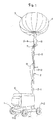
- Fig. 1 is a perspective view for showing one preferred embodiment of a light projector of this invention.
- This light projector A is comprised of a power generator 6; a bogie 1 for mounting the power generator 6; an extendable or retractable supporting column 2 vertically installed at the bogie 1; a balloon 4 installed at the upper end of the extendable or retractable supporting column 2; and a lighting instrument 3 having at least an electric bulb 5 stored in this balloon 4.
- This light projector is configured such that the power generator 6 and the lighting instrument 3 can be electrically energized to cause the lighting instrument 3 to be lit through electrical supplying from the power generator 6, glaring light supplied from the electric bulb 5 is passed through the balloon 4 and changed into a soft light not showing any glaring state and the light can be projected in an outer entire circumferential direction of the balloon 4.
- the bogie 1 is constructed such that wheels 1-2 are rotationally supported at front, rear, right and left portions of a vehicle body base 1-1, a power generator 6 having wheels is removably mounted on the bogie and at the same time the extendable or retractable supporting column 2 is vertically installed at the rear part.
- the power generator 6 has no wheels at all and the power generator 6 is removably mounted on or fixed on the bogie 1 and so this installing state is not specifically restricted.
- the extendable or retractable supporting column 2 is formed such that a main base column 2-1 is vertically installed at an upper surface of a rear part of the bogie 1, at least one hollow tube column having its inner diameter gradually decreased against the main base column 2-1 and two middle tube columns 2-2, 2-3 as seen in Fig. 1 are freely fitted in sequence into the main base column 2-1 in such a way that the hollow tube columns can be slid in an upward or downward direction, and these middle tube columns 2-2, 2-3 are slid up and down in sequence by a well-known ascending or descending means, thereby a height of the lighting instrument 3 can be properly changed and set.
- a connecting column 2-4 at the upper-most stage is removably inserted into the upper end of the middle tube column 2-3 through a joint member 7 and connected to it, thereby the lighting instrument 3 can be installed.
- a plug for a cable 9 electrically energizing the power generator 6 and a plug for a cable 8 electrically energizing the lighting instrument 3 are inserted into the joint member 7, thereby the power generator 6 and the lighting instrument 3 are electrically connected in such a way that they can be electrically energized, the electric bulb 5 is lit with electricity supplied from the power generator 6 and at the same time an air suction device 10 to be described later is operated.
- the ascending or descending means for sliding up and down each of the middle tube columns 2-2, 2-3 is not restricted in particular, it can be illustrated as examples to provide one configuration in which the extremity end of a wire wound around a winch arranged at the main base tube column 2-1, for example, is connected to the middle tube column 2-3 and at the same time, a middle portion of the wire is applied to pulleys arranged at the middle tube columns 2-2, 2-3 and each of the middle tube columns 2-2, 2-3 is ascended or descended by taking-up or feeding out the wire through the winch, or the other configuration in which an operation for ascending or descending each of the middle tube columns 2-2, 2-3 can be performed manually under utilization of a repelling force of a gas damper assembled into the base main column 2-1.
- a cable 9 supplied from the power generator 6 is partially supported at the extendable or retractable supporting column 2.
- the cable 9 is extended by each of the supporting portions and in turn when an operation for descending each of the middle tube columns 2-2, 2-3 is carried out, the cable 9 is collected in a loop shape.
- the lighting instrument 3 is comprised of a frame body 3-1 assembled in a grid manner, formed in a substantial cylindrical shape and storing the electric bulb 5; a lower supporting member 3-2 fixed to the lower part of the frame body 3-1; an upper supporting member 3-3 fixed to an upper part of the frame body 3-1; an air suction device 10 arranged above the lower supporting member 3-2; and a socket 11 with the electric bulb 5 being installed to be faced downward.
- the frame body 3-1 is vertically arranged and fixed at the upper end of the extendable or retractable supporting column 2 by the lower supporting member 3-2, the balloon 4 is held by the lower supporting member 3-2 and the upper supporting member 3-3, the frame body 3-1 is held by the lower supporting member 3-2 and the upper supporting member 3-3 and then the opposing location of the balloon 4 is fixed to the frame body 3-1.
- the frame body 3-1 is made such that several upward rods 3-10 of metallic wire material having a desired rigidity and having upper and lower ends bent at a proper length are arranged around the electric bulb 5 and at the same time a plurality of ring rods 3-11a having a larger diameter than that of the electric bulb 5 are fixed to enclose these upward rods 3-10, a plurality of ring rods 3-11b having a smaller diameter than that of the ring rods 3-11a are fixed to enclose the portions drawn inside the upper part and the lower part of the upward rods 3-10 and frame assembled into a substantial cylindrical shape with the upper and lower ends being drawn.
- a substantial central part of the frame body 3-1 is formed with an opening or closing door 12 for replacing the electric bulb 5 and at the same time the bulb holder 13 slidably engaged with each of the upward rods 3-10 in an upward or downward direction is installed inside the frame body 3-1.
- the opening or closing door 12 is frame assembled to have a size under application of the same metallic wire material as that of the frame body 3-1 over a substantial entire length in a height direction by about 1/3 in a circumferential direction in respect to the outer circumferential part of the frame body 3-1, the door is installed at an opening part formed at the outer circumferential part of the frame body 3-1 in the same size as that of the opening or closing door 12 in such a way that the door can be opened only at one side thereof and when a filament at the bulb 5 is cut, a replacement of the bulb can be easily carried out.
- the bulb holder 13 is made such that an extremity end protrusion 5-1 is fitted from above to inner end portions of three engaging arm pieces 13-2 arranged to extend in a radial direction from the central part of the frame body 3-1 toward either the upward rods 10 in an upward rod 12-1 of the opening or closing door 12 so as to form a holding part 13-1 for holding the electric bulb 5, a side edge at an outer end portion of each of the engaging arm pieces 13-2 is provided with an engaging notch 14a slidably engaged with either the upward rods 3-10 or the upward rod 12-1, and further the engaging arm pieces 13-2 of double directions engaged with the upward rods 3-10 are provided with engaging pieces 15 which are fixed at their inner ends to the engaging arm pieces 13-2 and engaged with the upward rods at their outer ends in such a way that they can be engaged with or disengaged from them.
- the engaging pieces 15 are composed of spring plate members, wherein an outside part of the inner end portion fixed to the engaging arm piece 13-2 is applied as an inclined part 15a bent with its outer end part becoming an upper level, and a side edge of the outer end part is provided with an engaging notch 14b engaged with the upward rod 3-10 in such a way that it is faced reverse to that of the engaging notch 14a. In this way, under a state shown in Figs.
- the engaging notch 14b is press contacted with the upward rod 3-10 by a spring action of the inclined part 15a so as to restrict an upward or downward sliding of the bulb holder 13 and in turn when the inclined part 15a is pushed toward the engaging arm piece 13-2, the spring action does not occur to enable the bulb holder 13 to slide in an upward or downward direction, and the bulb holder 13 can be engaged at a proper position where the electric bulb 5 held in a downward direction can be held.
- means for engaging the bulb holder 13 at a proper height position is not limited to a form using the engaging pieces 15 described above, but it may also be applicable that as shown in Fig. 8 or Fig. 10, for example, each of the upward rods (supporting columns) of the frame body is provided with a spring 55, its repelling force is utilized to bias the electric bulb holder 13 in an upward direction and to be held at a proper height position.
- the lower supporting member 3-2 fixed to the lower part of the frame body 3-1 is comprised of an outer plate 3-20 arranged outside the balloon 4 and an inner plate 3-21 cooperatively arranged at a lower end of the frame body 3-1.
- An outer skin of the balloon 4 is held at an inner side and an outer side of the balloon 4 by these outer plate 3-20 and inner plate 3-21 through an inside seal member 20 and an outside seal member 20, and the outer plate 3-20 is connected to the inner plate 3-21 with bolts 21 to cause a central location at the lower surface of the balloon 4 to be tightly fixed at the lower part of the frame body 3-1 under no air leakage state.
- the outer plate 3-20 is a disk plate made of desired metal or hard synthetic resin and the like.
- An upper end portion of the connecting column 2-4 described above is inserted into an insertion cylinder 17 fixed to its lower surface side and the inserted state is fixed with a stopper member 17a such as a bolt and the like so as to fix the frame body 3-1 to the upper end of the connecting column 2-4 in its upright installed state.
- the inner plate 3-21 is a disk plate made of the same quality material as that of the outer plate 3-20.
- a cylindrical casing 18 is fixed to its upper surface side and at the same time a connecting plate 19 fixed to the lower end of the frame body 3-1 is fixed to the upper surface of the casing 18.
- the air suction device 10 acting as the balloon bulging-out means composed of a fan motor is mounted at the upper surface of a connecting plate 19. Under an action of the air suction device 10, surrounding air is fed into the balloon 4 through aeration holes 22 formed at the outer plate 3-20, the inner plate 3-21 and the connecting plate 19 and through the casing 18 so as to bulge out the balloon 4.
- the upper supporting member 3-3 fixed to the upper part of the frame body 3-1 is comprised of an outer plate 3-31 and an inner plate 3-30 cooperatively arranged at an upper end part of the frame body 3-1.
- the outer skin of the balloon 4 is held at its inner side and outer side of the balloon 4 by these outer plate 3-31 and inner plate 3-30 through the inside seal member 20 and the outside seal member 20, and the outer plate 3-31 is fastened onto the upper part of the frame body 3-1 with bolts 21' at the inner plate 3-30, the central location of the upper surface of the balloon 4 is rigidly fixed to the upper part of the frame body 3-1 under no air leakage.
- the inner plate 3-30 and the outer plate 3-31 are disk plates made of desired metal or hard synthetic resin and the like.
- the inner plate 3-30 is connected to a connecting plate 23 fixed to the upper end of the frame body 3-1.
- the socket 11 for the electric bulb 5 and a protection cylinder 24 for protecting the socket 11 are fixed to the lower surface of the connecting plate 23.
- the balloon 4 is not limited in particular if it is an item which can dampen light got from the electric bulb 5, supply air inside the balloon and can be bulged out into a desired shape.
- a balloon having a substantial lateral long ellipsoidal shape composed of an outer skin such as a cloth or a synthetic resin film or the like.
- the lower surface at the central location of the balloon 4 is held by the lower supporting member 3-2 and its upper surface is held by the upper supporting member 3-3, respectively, and the frame body 3-1 is held by the lower supporting member 3-2 and the upper supporting member 3-3 and rigidly fixed to the upper and lower ends of the frame body 3-1.
- the electric bulb 5 is held in the frame body 3-1 in a downward facing direction and at the same time the lighting instrument 3 provided with the air suction device 10 at its lower part is arranged in a storing state, the air suction device 10 is operated through supplying electricity from the power generator 6 to bulge out the balloon 4 and the electric bulb 5 is lit.
- the light projector of this example constructed as described above, when the electric bulb 5 is lit, the light is changed into a soft feeling light through the balloon 4 and the light can be projected against the outer entire circumferential direction of the balloon 4, so that glaring is not felt and the light can be radiated over a wide range.
- the power generator 6, the extendable or retractable supporting column 2, the lighting instrument 3 and the balloon 4 can be moved together and their handling can be easily carried out and they can be installed at optional locations.
- the opposing location at the balloon 4 i.e. the central location of the upper surface and the central location of the lower surface of the balloon 4 are rigidly fixed to the upper part and the lower part of the frame body 3-1 by the upper supporting member 3-3 and the lower supporting member 3-2 installed at the frame body 3-1 of the lighting instrument 3, the bulged-out state of the balloon 4 can be held as much as possible even if the balloon 4 is swung with a strong wind, for example.
- the electric bulb 5 is held in the frame body 3-1 in a downward facing manner, it is possible to avoid a possibility that rain water and the like enters the socket 11 and a water-proof characteristic can be improved.
- the opening or closing door 12 around the frame body 3-1 is opened to enable a replacement of the electric bulb to be easily carried out.
- Figs. 5 to 7 illustrate light shielding members for restricting a light projecting range by the aforesaid balloon 4. These light shielding members are properly installed outside or inside the balloon 4 to make a partial shielding of a light projecting direction from the balloon 4 in the case that leakage of light to a civilian house at a working site near the civilian house may cause a trouble to the civilian house and to restrict the light projecting range.
- the light shielding member shown in Fig. 5 is a covering film 25 having a light shielding characteristic.
- One or a plurality of covering films 25 can be properly installed outside the balloon 4. If the material does not pass the light from the electric bulb 5, the material of the covering film 25 is not particularly restricted. However, it is preferable to apply either a thin fabric or a thin synthetic resin sheet or film having a flexibility which can be easily installed along the outside part of the bulged-out balloon 4, for example.
- This covering film 25 is formed into such a shape as shown in Fig. 5, for example, one of a pair of male or female velvet fasteners 26 (for example, a male side) is fixed by sewing or adhesion or other desired fixing means along an edge part of the inner surface side, the other fastener (for example, a female side) is fixed along the outer surface of the balloon 4 in response to either a size or shape of the covering film 25, one or several covering films 25 are optionally installed at an outside location of the balloon 4 through an engaged or disengaged connection of the velvet fasteners 26, thereby the light projecting direction of the balloon 4 is optionally set.
- the covering film 25 As means for removably fixing the covering film 25 to the outside of the balloon 4, it is not limited to application of the velvet fasteners 26 and it is satisfactory if the means such as hooks and buttons or the like capable of rigidly fastening the covering film 25 to the outside part of the balloon 4 and capable of being easily engaged with or disengaged from the balloon is applied.
- Fig. 6 is illustrated an example in which the frame body 3-1 of the aforesaid lighting instrument 3 is formed only with some straight upward rods 3-10 and at the same time the louvers 27 acting as the light shielding members are installed at each of the upward rods 3-10 in such a way that they can be opened or closed.
- the upward rods 3-10 in this example are vertically installed in an equal space at outer edges of the connecting plates 19, 23 over the connecting plate 19 at the side of the aforesaid lower supporting member 3-2 and the connecting plate 23 at the upper supporting member 3-3 so as to form the frame body 3-1 and at the same time the louvers 27 curved in an arcuate shape are installed at openings 28 of the adjoining upward rods 3-10 themselves.
- the louvers 27 have their side edges pivotally supported at the upward rods 3-10 and rotatably supported there.
- each one of or several louvers 27 is rotatably installed at each of the openings 28 at the frame body 3-1, the opening 28 at an optional location is closed by the louver 27 to prevent light got from the electric bulb 5 from partially leaked out of the balloon. Then, the light from the electric bulb 5 is not radiated from the opening 28 between each of the upward rods 3-10 of the frame body 3-1 closed by the louvers 27, the light is radiated from the opening 28 between each of the upward rods 3-10, 3-10 not provided with the louvers 27 to enable the light projecting direction with the balloon 4 can be optionally set.
- each of the louvers 27 is rotated to open all the openings 28 to enable the light from the electric bulb 5 to be radiated against the outside entire circumferential direction of the balloon 4.
- Reference numeral 29 in Fig. 6 denotes each of spring members installed at the upward rods 3-10 having the louvers 27 rotatably and pivotally supported.
- the repelling force of the spring members 29 biases the louvers 27 in a closing direction or an opening direction.
- a covering plate 30 acting as a light shielding member which is removably installed between the adjoining upward rods 3-10 and 3-10 of the frame body 3-1 shown in Fig. 6 in place of the aforesaid louvers 27.
- This covering plate 30 is provided with engagement members 31 removably engaged between the adjoining upward rods 3-10, 3-10 at a rear side of the arcuate curved plate covering the aforesaid openings 28.
- This covering plate is constructed such that one or several covering plates 30 are prepared in advance, the opening 28 at optional location is closed by the covering plate 30 to prevent the light of the electric bulb 5 from being radiated at the opening 28, the light is radiated from the opening 28 where the covering plate 30 is not installed and the light projecting direction can be optionally set through the balloon 4.
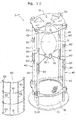
- FIG. 8 to 10 is shown an example in which the structures of the frame body 3-1 of the aforesaid lighting instrument 3 and the balloon 4 are changed, respectively.
- a frame body 3-1' shown in Fig. 8 has a supporting column structure of high strength in which a plurality of supporting columns 40 are raised between the upper part and the lower part of the frame body.
- this frame body 3-1' is made such that four supporting columns 40 are vertically arranged between the inner plate 3-21 of the lower supporting member 3-2 and the inner plate 3-30 of the upper supporting member 3-3. These supporting columns 40 are raised in every equal space at the outer edges of each of the aforesaid inner plates 3-21, 3-30.
- Each of the supporting columns 40 is comprised of three columns made of metal or synthetic resin.
- a middle column 41 acting as the first column is provided with an upper column 42 acting as a second column having a smaller diameter than that of the middle column 41 and a lower column 43 acting as a third column.
- the upper column 42 is slidably inserted into the middle column 41 at the upper end part of the middle column 41, and the lower column 43 is slidably inserted into the middle column 41 at the lower end of the middle column 41, respectively, so as to cause a length of the supporting column to be adjustable.
- each of the upper end and lower end of each of the middle columns 41 is provided with a slit groove 44, a diameter of the slit groove is made to be expanded or retracted and at the same time a fastening band 45 is installed there, fastening of the fastening band 45 causes the diameters of the upper end and the lower end of the middle column 41 to be optionally shrunk to restrict a sliding motion of the upper column 42 and the lower column 43, a protruding size of each of the upper column 42 and the lower column 43 in respect to the middle column 41 is optionally adjusted and a length of each of the supporting columns 40 can be adjusted.
- the upper column 42 is fixed to the inner plate 3-30 by bolts 21' for use in fixing the outer plate 3-31 of the upper supporting member 3-3 to the inner plate 3-30.
- the lower column 43 is fixed to the inner plate 3-21 by bolts 21 for use in fixing the outer plate 3-20 of the lower supporting member 3-2 to the inner plate 3-20.
- An upper socket plate 51 is installed at the upper column 42 of each of the supporting columns 40 in such a way that it can be slid in an upward or downward direction, and the socket 11 is arranged at the lower surface of the upper socket plate 51 and an electric bulb 5a is installed while being faced downward to enable the position of the electric bulb 5a to be adjusted in an upward or downward direction.
- the upper socket plate 51 is fixed to a fastening band 50 of which fixing position can be changed in respect to each of the upper columns 42.
- the middle column 41 of each of the supporting columns 40 is provided with a lower socket plate 53 in such a way that it can be slid in an upward or downward direction.
- the lower surface of the lower socket plate 53 is provided with the socket 11 to cause an electric bulb 5b to be installed while being faced downward, thereby the position of the electric bulb 5b can be adjusted in an upward or downward direction.
- the lower socket plate 53 is fixed to a fastening band 52 installed in such a way that its fixing position can be changed.
- the electric bulb holder 13 for holding each of the aforesaid electric bulbs 5a, 5b is installed at the middle column 41 in such a way that it can be slid in an upward or downward direction.
- the electric bulb holder 13 is biased upwardly by a spring 55 held by a fastening band 54 of which fixing position can be freely changed against the middle column 41 and fixed at a proper height position where the electric bulbs 5a, 5b can be held.
- each of the height positions of the electric bulb 5a and the electric bulb 5b can be separately adjusted and the position of the light source can be set properly in response to a shape or a size of the balloon.
- each of the height positions of the electric bulb holders 13 can be separately adjusted and each of the electric bulbs 5a, 5b of which height positions have been changed can be held by each of the electric bulb holders 13, respectively.
- a protecting frame 60 shown in Fig. 10 is installed between the adjoining supporting columns 40, 40 of the frame body 3-1'.
- the protecting frame 60 is composed of a metal net-like frame member where a plurality of arcuate curved lateral wire members 61 and linear upward wire members 62 are combined to each other. Both right and left end portions of the lateral wire members 61 are bent inwardly to form hook parts 63, each of the hook parts 63 is resiliently engaged with the supporting columns 40 and each of the hooks is removably installed between the adjoining supporting columns 40, 40.
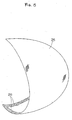
- a balloon 4' composed of three segments, i.e. a barrel part 4a, an upper surface part 4b and a lower surface part 4c.
- the barrel part 4a is formed by a cylindrical sheet member 4a-1 made of sheet material formed into a cylindrical shape while both end edges of the sheet of lateral long rectangular shape made of nylon etc.
- an upper circular sheet member 4a-2 formed into a circular shape with the same sheet material as that of the cylindrical sheet member 4a-1 and fixed by sewing and adhering or the like to the opening edge to close the upper opening surface 4a-1' and the lower opening surface 4a-1" of the cylindrical sheet member 4a-1; and a lower circular sheet member 4a-3.
- the upper surface 4b and the lower surface 4c composed of the same quality sheet material as that of the cylindrical sheet member 4a-1 are removably attached to openings 4a-2', 4a-3' arranged at the upper circular sheet member 4a-2 and the lower circular sheet member 4a-3.
- the barrel part 4a is formed by three fixing segments, i.e. a fixed segment 71 such as sewing and adhering or the like at the cylindrical sheet member 4a-1; and fixing segments 72, 73 such as sewing and adhering or the like of the upper circular sheet member 4a-2, the lower circular sheet member 4a-3 in respect to the upper opening surface 4a-1', the lower opening surface 4a-1" to enable the circular cylindrical balloon 4' not producing any wrinkles to be formed.
- a fixed segment 71 such as sewing and adhering or the like at the cylindrical sheet member 4a-1
- fixing segments 72, 73 such as sewing and adhering or the like of the upper circular sheet member 4a-2, the lower circular sheet member 4a-3 in respect to the upper opening surface 4a-1', the lower opening surface 4a-1" to enable the circular cylindrical balloon 4' not producing any wrinkles to be formed.
- a shape of the balloon 4' can be applied in various kinds of shape such as a substantial lateral elongated drum shape, a substantial truncated cone shape, an inverse truncated cone shape, a figure, an animal, a building and character other than the substantial upward longitudinal drum shape shown.
- the balloon 4' in this example is fixed in such a way that the upper surface 4b is held by the outer plate 3-31 and the inner plate 3-30; the lower surface 4c is held by the outer plate 3-20 and the inner plate 3-21 of the lower supporting member 3-2; and the barrel part 4a is removably attached by arranging an engaging means 80 to enable the openings 4a-2', 4a-3' arranged at the centers of the upper circular sheet member 4a-2 and the lower circular sheet member 4a-3 to be engaged with or disengaged from each of these upper surface 4b and lower surface 4c, respectively.
- the engagement means 80 in this example is a fastener type connecting means opened or closed under an operation provided from outside to the balloon 4', and more particularly, the upper surface 4b and the lower surface 4c are formed into a circular sheet state as shown in Fig. 9, an annular row of teeth 81 composed of one of the male or female teeth rows of the fastener is formed at an outer circumferential portion, and in turn an annular row of teeth 82 composed of the other of the male or female teeth rows of the fastener is formed along the opening edges of the openings 4a-2', 4a-3', an opening or closing fitting 83 is slidably attached to one of the rows of teeth, and both teeth rows 81, 82 are connected or separated through a sliding operation of the opening or closing fitting 83.
- either the aforesaid frame body 3-1 or 3-1' is arranged between each of the inner plates 3-21, 3-30 of the lower supporting member 3-2 and the upper supporting member 3-3.
- the barrel 4a of the balloon 4' is connected to the upper surface 4b and the lower surface 4c, and under this state, the balloon 4' is rigidly fixed to either the frame body 3-1 or 3-1'.
- the opening or closing fitting 83 is slid in the opening direction from this state to cause the annular row of teeth 81 to be separated from the annular row of teeth 82 (the fastener is opened)
- the upper surface 4b and the lower surface 4c are left at the upper part and the lower part of the frame body 3-1 or 3-1' and then the barrel part 4a of the balloon 4' can be easily removed from either the frame body 3-1 or 3-1'.
- other barrels having different shapes and different sizes are replaced with the former barrel and installed.
- the frame body 3-1' shown in Fig. 3 is applied to enable the height size of the frame body 3-1' or positions of the electric bulbs 5a, 5b can be properly adjusted in compliance with the barrels.
- the upper surface 4b and the lower surface 4c of the balloon 4' are removably attached to the barrel 4a by the fastener type connecting means.
- this invention is not limited to this arrangement.
- the aforesaid cylindrical sheet member 4a-1 is applied as a barrel of the balloon
- the annular row of teeth 81 composed of one row of male or female teeth is formed at opening edges of the upper opening surface 4a-1' and the lower opening surface 4a-1" of the barrel and in turn, the circular sheet members 4a-2, 4a-3 closing the upper opening surface 4a-1' and the lower opening surface 4a-1" are applied as an upper surface and a lower surface of the balloon.
- the annular row of teeth 82 composed of the other row of male or female teeth of the fastener is formed at the outer circumferential portions of the upper surface and the lower surface.
- the opening or closing fitting 83 is slidably attached to any one of the rows of teeth, the upper surface and the lower surface composed of the circular sheet members 4a-2, 4a-3 are removably attached to the barrel composed of the cylindrical sheet member 4a-1.
- engagement means is not limited to the aforesaid fastener-type connecting means, but it is possible to apply various kinds of engagement means such as hooks and buttons where the male member and the female member are engaged to each other.
- the frame body 3-1" shown in Fig. 10 is provided with a collet nut 90 acting as a member for restricting the sliding motion of the upper column 42 and the lower column 43 inserted into the middle column 41 in place of the fastening band 45 for the frame body 3-1' shown in Fig. 8.
- a collet nut 90 acting as a member for restricting the sliding motion of the upper column 42 and the lower column 43 inserted into the middle column 41 in place of the fastening band 45 for the frame body 3-1' shown in Fig. 8.
- Other composing elements than the foregoing are similar to the elements described above, so that their duplex description will be eliminated.
- the light projector of this invention has been constituted as described above, so that the light from the light projector is passed through the balloon to enable the light to be changed into a light not feeling a glare and radiated in a soft light and the light can be radiated against the outer entire circumferential direction of the balloon.
Abstract
Description
- This invention relates to a light projector used as a nighttime lighting unit applied in a work site, a game ground and a camp or the like. More particularly, this invention relates to a light projector which can be effectively used as a nighttime lighting unit for a road construction or the like, for example, by radiating light from a light source indirectly and reducing a lighting glare.
- It is well known in the prior art to provide a light projector in which a desired number of spot-light type lighting instruments for use in radiating light of a lamp (an electrical bulb) in a forward direction by a reflector are installed at an upper end of an extendable or retractable supporting column vertically installed at a bogie for use in mounting a power generator.
- In this type of light projector, it is of course apparent that the light (projected light) radiated from the aforesaid lighting instrument is bright to cause a worker at site to easily perform the work there. However, when this is applied at a nighttime road construction work, there occurs a possibility that the projected light is too bright for a driver of running vehicle and in particular, this may cause a troublesome state at the work site such as a highway and the like. In addition, the light radiated from the aforesaid lighting instrument is limited only in a forward direction as to the light projecting direction with a reflector, so that its light projecting range becomes narrow and it becomes a disadvantage that a plurality of light projectors are required in the case that the work area is wide.
- This invention has been invented in view of the prior art circumstances and it is an object of this invention to provide a new light projector in which no glaring is felt by a driver and the light can be radiated in a wide range.
- In order to accomplish the aforesaid object, the light projector of the present invention is comprised of a power generator; a bogie for mounting the power generator; an extendable or retractable supporting column vertically installed at the bogie; a balloon arranged at an upper end of the extendable or retractable supporting column; and a lighting instrument stored in the balloon, and characterized in that the power generator and the lighting instrument can be electrically energized.
- In accordance with the light projector of this invention constituted as described above, when the lighting instrument is lit, the light is changed into a soft-feeling light through the balloon so as to enable the light to be projected in an outward entire circumferential direction, so that it is possible to radiate the light over a wide range without causing a driver to feel glare.
- In addition, this invention is constructed such that the aforesaid lighting instrument is comprised of an electric bulb, a frame body for holding the electric bulb and a balloon expanding means for expanding the balloon, and characterized in that there are provided an upper supporting member and a lower supporting member for holding the balloon, and the frame body is held by the upper supporting member and the lower supporting member.
- In such a construction as described above, the balloon is rigidly fixed to the main body, so that the bulged-out state of the balloon can be kept tightly.
- Further, this invention is characterized in that the upper supporting member and the lower supporting member are comprised of an inner plate arranged inside the balloon and an outer plate arranged outside the balloon, and an optional part of the balloon is held by these inner plate and outer plate.
- In such a configuration as above, this invention provides a fixed structure in which an opposing portion in the balloon is held by the surfaces of the inner plate and the outer plate, so that there is no possibility that the balloon is broken or has a punctured hole at the fixed portion and the balloon can be held tightly.
- Further, this invention is characterized in that the frame body is comprised of a plurality of supporting columns raised between the upper part and the lower part of the frame body.
- In such a configuration as above, the frame body becomes a rigid structure comprised of a plurality of supporting columns.
- In addition, this invention is characterized in that each of the supporting columns of the frame body is comprised of at least a first column and a second column having a smaller diameter than that of the first column and the second column is slidably inserted into the first column.
- In such a configuration as above, each of the second columns is slid and its sliding motion is restricted at optional position to enable a length of the frame body to be optionally adjusted.
- Further, this invention is characterized in that the balloon is comprised of an upper surface part, a barrel part and a lower surface part, and both the upper surface part and the lower surface part are provided with an engagement means to cause the barrel part to be engaged or disengaged.
- In such a configuration as above, the barrel part of the balloon can be easily removed by operating the engagement means.
- Further, this invention is characterized in that one or a plurality of covering films with light-shielding characteristic are formed at optional portions outside the balloon in such a way that they are removably and properly installed.
- In such a configuration as above, the covering films are installed at optional locations outside the balloon to enable light radiated from a lighting instrument to be partially shielded and a light projecting range to be properly set.
- Further, this invention is characterized in that one or a plurality of louvers or covering plates having a light shielding characteristic are installed in such a way that they can be opened or closed or engaged or disengaged.
- In such a configuration as above, an optional louver fixed around the barrel part of the frame body is opened or closed or the shielding plates are installed at optional locations around the frame body to enable light radiated from the lighting instrument to be partially shielded and a light projecting range to be properly set.
-
- Fig. 1 is a perspective view for showing one preferred embodiment of a light projector of this invention.
- Fig. 2 is an enlarged longitudinal sectional view for showing a central part of a balloon.
- Fig. 3 is a top plan view in cross section for showing a frame body of the lighting instrument.
- Fig. 4 is a perspective view for showing a relation between an electric bulb and an electric bulb-holding member.
- Fig. 5 is a perspective view for showing one example of a shielding film installed outside the balloon.
- Fig. 6 is a perspective view for showing an example in which louvers are installed at the frame body of the lighting instrument.
- Fig. 7 is a perspective view for showing an example of a shielding plate installed at the frame body of the lighting instrument.
- Fig. 8 is an enlarged longitudinal view in section of a central part of the balloon for showing an example in which the frame body of the lighting instrument is a supporting column structure.
- Fig. 9 is an exploded perspective view for showing a balloon comprised of three segments.
- Fig. 10 is a perspective view for showing another example of the frame body acting as a column structure.
- Referring now to the accompanying drawings, a preferred embodiment of this invention will be described.
- Fig. 1 is a perspective view for showing one preferred embodiment of a light projector of this invention. This light projector A is comprised of a power generator 6; a
bogie 1 for mounting the power generator 6; an extendable or retractable supportingcolumn 2 vertically installed at thebogie 1; aballoon 4 installed at the upper end of the extendable or retractable supportingcolumn 2; and alighting instrument 3 having at least anelectric bulb 5 stored in thisballoon 4. This light projector is configured such that the power generator 6 and thelighting instrument 3 can be electrically energized to cause thelighting instrument 3 to be lit through electrical supplying from the power generator 6, glaring light supplied from theelectric bulb 5 is passed through theballoon 4 and changed into a soft light not showing any glaring state and the light can be projected in an outer entire circumferential direction of theballoon 4. - The
bogie 1 is constructed such that wheels 1-2 are rotationally supported at front, rear, right and left portions of a vehicle body base 1-1, a power generator 6 having wheels is removably mounted on the bogie and at the same time the extendable or retractable supportingcolumn 2 is vertically installed at the rear part. - It is of course available that the power generator 6 has no wheels at all and the power generator 6 is removably mounted on or fixed on the
bogie 1 and so this installing state is not specifically restricted. - The extendable or retractable supporting
column 2 is formed such that a main base column 2-1 is vertically installed at an upper surface of a rear part of thebogie 1, at least one hollow tube column having its inner diameter gradually decreased against the main base column 2-1 and two middle tube columns 2-2, 2-3 as seen in Fig. 1 are freely fitted in sequence into the main base column 2-1 in such a way that the hollow tube columns can be slid in an upward or downward direction, and these middle tube columns 2-2, 2-3 are slid up and down in sequence by a well-known ascending or descending means, thereby a height of thelighting instrument 3 can be properly changed and set. - Then, a connecting column 2-4 at the upper-most stage is removably inserted into the upper end of the middle tube column 2-3 through a joint member 7 and connected to it, thereby the
lighting instrument 3 can be installed. - A plug for a
cable 9 electrically energizing the power generator 6 and a plug for a cable 8 electrically energizing thelighting instrument 3 are inserted into the joint member 7, thereby the power generator 6 and thelighting instrument 3 are electrically connected in such a way that they can be electrically energized, theelectric bulb 5 is lit with electricity supplied from the power generator 6 and at the same time anair suction device 10 to be described later is operated. - Although the ascending or descending means for sliding up and down each of the middle tube columns 2-2, 2-3 is not restricted in particular, it can be illustrated as examples to provide one configuration in which the extremity end of a wire wound around a winch arranged at the main base tube column 2-1, for example, is connected to the middle tube column 2-3 and at the same time, a middle portion of the wire is applied to pulleys arranged at the middle tube columns 2-2, 2-3 and each of the middle tube columns 2-2, 2-3 is ascended or descended by taking-up or feeding out the wire through the winch, or the other configuration in which an operation for ascending or descending each of the middle tube columns 2-2, 2-3 can be performed manually under utilization of a repelling force of a gas damper assembled into the base main column 2-1.
- In addition, a
cable 9 supplied from the power generator 6 is partially supported at the extendable or retractable supportingcolumn 2. When an operation for ascending each of the middle tube columns 2-2, 2-3 is carried out against the base main column 2-1, thecable 9 is extended by each of the supporting portions and in turn when an operation for descending each of the middle tube columns 2-2, 2-3 is carried out, thecable 9 is collected in a loop shape. - As shown in Figs. 2 and 3, the
lighting instrument 3 is comprised of a frame body 3-1 assembled in a grid manner, formed in a substantial cylindrical shape and storing theelectric bulb 5; a lower supporting member 3-2 fixed to the lower part of the frame body 3-1; an upper supporting member 3-3 fixed to an upper part of the frame body 3-1; anair suction device 10 arranged above the lower supporting member 3-2; and asocket 11 with theelectric bulb 5 being installed to be faced downward. The frame body 3-1 is vertically arranged and fixed at the upper end of the extendable or retractable supportingcolumn 2 by the lower supporting member 3-2, theballoon 4 is held by the lower supporting member 3-2 and the upper supporting member 3-3, the frame body 3-1 is held by the lower supporting member 3-2 and the upper supporting member 3-3 and then the opposing location of theballoon 4 is fixed to the frame body 3-1. - The frame body 3-1 is made such that several upward rods 3-10 of metallic wire material having a desired rigidity and having upper and lower ends bent at a proper length are arranged around the
electric bulb 5 and at the same time a plurality of ring rods 3-11a having a larger diameter than that of theelectric bulb 5 are fixed to enclose these upward rods 3-10, a plurality of ring rods 3-11b having a smaller diameter than that of the ring rods 3-11a are fixed to enclose the portions drawn inside the upper part and the lower part of the upward rods 3-10 and frame assembled into a substantial cylindrical shape with the upper and lower ends being drawn. - In addition, a substantial central part of the frame body 3-1 is formed with an opening or closing
door 12 for replacing theelectric bulb 5 and at the same time thebulb holder 13 slidably engaged with each of the upward rods 3-10 in an upward or downward direction is installed inside the frame body 3-1. - The opening or closing
door 12 is frame assembled to have a size under application of the same metallic wire material as that of the frame body 3-1 over a substantial entire length in a height direction by about 1/3 in a circumferential direction in respect to the outer circumferential part of the frame body 3-1, the door is installed at an opening part formed at the outer circumferential part of the frame body 3-1 in the same size as that of the opening or closingdoor 12 in such a way that the door can be opened only at one side thereof and when a filament at thebulb 5 is cut, a replacement of the bulb can be easily carried out. - As shown in Figs. 3 and 4, the
bulb holder 13 is made such that an extremity end protrusion 5-1 is fitted from above to inner end portions of three engaging arm pieces 13-2 arranged to extend in a radial direction from the central part of the frame body 3-1 toward either theupward rods 10 in an upward rod 12-1 of the opening or closingdoor 12 so as to form a holding part 13-1 for holding theelectric bulb 5, a side edge at an outer end portion of each of the engaging arm pieces 13-2 is provided with anengaging notch 14a slidably engaged with either the upward rods 3-10 or the upward rod 12-1, and further the engaging arm pieces 13-2 of double directions engaged with the upward rods 3-10 are provided withengaging pieces 15 which are fixed at their inner ends to the engaging arm pieces 13-2 and engaged with the upward rods at their outer ends in such a way that they can be engaged with or disengaged from them. - The
engaging pieces 15 are composed of spring plate members, wherein an outside part of the inner end portion fixed to the engaging arm piece 13-2 is applied as aninclined part 15a bent with its outer end part becoming an upper level, and a side edge of the outer end part is provided with anengaging notch 14b engaged with the upward rod 3-10 in such a way that it is faced reverse to that of theengaging notch 14a. In this way, under a state shown in Figs. 2 and 4, theengaging notch 14b is press contacted with the upward rod 3-10 by a spring action of theinclined part 15a so as to restrict an upward or downward sliding of thebulb holder 13 and in turn when theinclined part 15a is pushed toward the engaging arm piece 13-2, the spring action does not occur to enable thebulb holder 13 to slide in an upward or downward direction, and thebulb holder 13 can be engaged at a proper position where theelectric bulb 5 held in a downward direction can be held. - Further, means for engaging the
bulb holder 13 at a proper height position is not limited to a form using theengaging pieces 15 described above, but it may also be applicable that as shown in Fig. 8 or Fig. 10, for example, each of the upward rods (supporting columns) of the frame body is provided with aspring 55, its repelling force is utilized to bias theelectric bulb holder 13 in an upward direction and to be held at a proper height position. - The lower supporting member 3-2 fixed to the lower part of the frame body 3-1 is comprised of an outer plate 3-20 arranged outside the
balloon 4 and an inner plate 3-21 cooperatively arranged at a lower end of the frame body 3-1. An outer skin of theballoon 4 is held at an inner side and an outer side of theballoon 4 by these outer plate 3-20 and inner plate 3-21 through aninside seal member 20 and anoutside seal member 20, and the outer plate 3-20 is connected to the inner plate 3-21 withbolts 21 to cause a central location at the lower surface of theballoon 4 to be tightly fixed at the lower part of the frame body 3-1 under no air leakage state. - The outer plate 3-20 is a disk plate made of desired metal or hard synthetic resin and the like. An upper end portion of the connecting column 2-4 described above is inserted into an
insertion cylinder 17 fixed to its lower surface side and the inserted state is fixed with astopper member 17a such as a bolt and the like so as to fix the frame body 3-1 to the upper end of the connecting column 2-4 in its upright installed state. - The inner plate 3-21 is a disk plate made of the same quality material as that of the outer plate 3-20. A
cylindrical casing 18 is fixed to its upper surface side and at the same time a connectingplate 19 fixed to the lower end of the frame body 3-1 is fixed to the upper surface of thecasing 18. - The
air suction device 10 acting as the balloon bulging-out means composed of a fan motor is mounted at the upper surface of a connectingplate 19. Under an action of theair suction device 10, surrounding air is fed into theballoon 4 through aeration holes 22 formed at the outer plate 3-20, the inner plate 3-21 and the connectingplate 19 and through thecasing 18 so as to bulge out theballoon 4. - The upper supporting member 3-3 fixed to the upper part of the frame body 3-1 is comprised of an outer plate 3-31 and an inner plate 3-30 cooperatively arranged at an upper end part of the frame body 3-1. The outer skin of the
balloon 4 is held at its inner side and outer side of theballoon 4 by these outer plate 3-31 and inner plate 3-30 through theinside seal member 20 and theoutside seal member 20, and the outer plate 3-31 is fastened onto the upper part of the frame body 3-1 with bolts 21' at the inner plate 3-30, the central location of the upper surface of theballoon 4 is rigidly fixed to the upper part of the frame body 3-1 under no air leakage. - The inner plate 3-30 and the outer plate 3-31 are disk plates made of desired metal or hard synthetic resin and the like. The inner plate 3-30 is connected to a connecting
plate 23 fixed to the upper end of the frame body 3-1. - The
socket 11 for theelectric bulb 5 and aprotection cylinder 24 for protecting thesocket 11 are fixed to the lower surface of the connectingplate 23. - The
balloon 4 is not limited in particular if it is an item which can dampen light got from theelectric bulb 5, supply air inside the balloon and can be bulged out into a desired shape. However, in the case of the example in this invention, there is applied a balloon having a substantial lateral long ellipsoidal shape composed of an outer skin such as a cloth or a synthetic resin film or the like. As described above, the lower surface at the central location of theballoon 4 is held by the lower supporting member 3-2 and its upper surface is held by the upper supporting member 3-3, respectively, and the frame body 3-1 is held by the lower supporting member 3-2 and the upper supporting member 3-3 and rigidly fixed to the upper and lower ends of the frame body 3-1. - At the inner central position of the
balloon 4, theelectric bulb 5 is held in the frame body 3-1 in a downward facing direction and at the same time thelighting instrument 3 provided with theair suction device 10 at its lower part is arranged in a storing state, theair suction device 10 is operated through supplying electricity from the power generator 6 to bulge out theballoon 4 and theelectric bulb 5 is lit. - In accordance with the light projector of this example constructed as described above, when the
electric bulb 5 is lit, the light is changed into a soft feeling light through theballoon 4 and the light can be projected against the outer entire circumferential direction of theballoon 4, so that glaring is not felt and the light can be radiated over a wide range. In addition, when a lighting place is to be changed at a work site and the like, the power generator 6, the extendable or retractable supportingcolumn 2, thelighting instrument 3 and theballoon 4 can be moved together and their handling can be easily carried out and they can be installed at optional locations. - In addition, since the opposing location at the
balloon 4, i.e. the central location of the upper surface and the central location of the lower surface of theballoon 4 are rigidly fixed to the upper part and the lower part of the frame body 3-1 by the upper supporting member 3-3 and the lower supporting member 3-2 installed at the frame body 3-1 of thelighting instrument 3, the bulged-out state of theballoon 4 can be held as much as possible even if theballoon 4 is swung with a strong wind, for example. - Further, since there is provided a holding type fixed structure in which the outer skin at the opposing location in the
balloon 4 is held by the surfaces of these plates under application of the outer plates 3-20, 3-31 and the inner plates 3-21, 3-30, there occurs no possibility that the balloon is broken or formed with holes at a fixing portion for theballoon 4 and thus it is possible that theballoon 4 can be rigidly held. - In addition, since the
electric bulb 5 is held in the frame body 3-1 in a downward facing manner, it is possible to avoid a possibility that rain water and the like enters thesocket 11 and a water-proof characteristic can be improved. - When a filament of the
electric bulb 5 is cut, the opening or closingdoor 12 around the frame body 3-1 is opened to enable a replacement of the electric bulb to be easily carried out. - Since there is employed a holding structure in which the electric bulb is held by the
electric bulb holder 13, it is possible to prevent an installed state of theelectric bulb 5 against thesocket 11 from being loosened and to attain its use with peace of mind. - Figs. 5 to 7 illustrate light shielding members for restricting a light projecting range by the
aforesaid balloon 4. These light shielding members are properly installed outside or inside theballoon 4 to make a partial shielding of a light projecting direction from theballoon 4 in the case that leakage of light to a civilian house at a working site near the civilian house may cause a trouble to the civilian house and to restrict the light projecting range. - The light shielding member shown in Fig. 5 is a covering film 25 having a light shielding characteristic. One or a plurality of covering films 25 can be properly installed outside the
balloon 4. If the material does not pass the light from theelectric bulb 5, the material of the covering film 25 is not particularly restricted. However, it is preferable to apply either a thin fabric or a thin synthetic resin sheet or film having a flexibility which can be easily installed along the outside part of the bulged-outballoon 4, for example. - This covering film 25 is formed into such a shape as shown in Fig. 5, for example, one of a pair of male or female velvet fasteners 26 (for example, a male side) is fixed by sewing or adhesion or other desired fixing means along an edge part of the inner surface side, the other fastener (for example, a female side) is fixed along the outer surface of the
balloon 4 in response to either a size or shape of the covering film 25, one or several covering films 25 are optionally installed at an outside location of theballoon 4 through an engaged or disengaged connection of thevelvet fasteners 26, thereby the light projecting direction of theballoon 4 is optionally set. - As means for removably fixing the covering film 25 to the outside of the
balloon 4, it is not limited to application of thevelvet fasteners 26 and it is satisfactory if the means such as hooks and buttons or the like capable of rigidly fastening the covering film 25 to the outside part of theballoon 4 and capable of being easily engaged with or disengaged from the balloon is applied. - In Fig. 6 is illustrated an example in which the frame body 3-1 of the
aforesaid lighting instrument 3 is formed only with some straight upward rods 3-10 and at the same time thelouvers 27 acting as the light shielding members are installed at each of the upward rods 3-10 in such a way that they can be opened or closed. - That is, the upward rods 3-10 in this example are vertically installed in an equal space at outer edges of the connecting
plates plate 19 at the side of the aforesaid lower supporting member 3-2 and the connectingplate 23 at the upper supporting member 3-3 so as to form the frame body 3-1 and at the same time thelouvers 27 curved in an arcuate shape are installed atopenings 28 of the adjoining upward rods 3-10 themselves. Thelouvers 27 have their side edges pivotally supported at the upward rods 3-10 and rotatably supported there. - In accordance with this example, each one of or
several louvers 27 is rotatably installed at each of theopenings 28 at the frame body 3-1, theopening 28 at an optional location is closed by thelouver 27 to prevent light got from theelectric bulb 5 from partially leaked out of the balloon. Then, the light from theelectric bulb 5 is not radiated from theopening 28 between each of the upward rods 3-10 of the frame body 3-1 closed by thelouvers 27, the light is radiated from theopening 28 between each of the upward rods 3-10, 3-10 not provided with thelouvers 27 to enable the light projecting direction with theballoon 4 can be optionally set. - When the light projector is used at a work site far from a civil house and the like (when a light projecting direction is not needed to be restricted), each of the
louvers 27 is rotated to open all theopenings 28 to enable the light from theelectric bulb 5 to be radiated against the outside entire circumferential direction of theballoon 4. -
Reference numeral 29 in Fig. 6 denotes each of spring members installed at the upward rods 3-10 having thelouvers 27 rotatably and pivotally supported. The repelling force of thespring members 29 biases thelouvers 27 in a closing direction or an opening direction. - In Fig. 7 is illustrated a
covering plate 30 acting as a light shielding member which is removably installed between the adjoining upward rods 3-10 and 3-10 of the frame body 3-1 shown in Fig. 6 in place of theaforesaid louvers 27. This coveringplate 30 is provided withengagement members 31 removably engaged between the adjoining upward rods 3-10, 3-10 at a rear side of the arcuate curved plate covering theaforesaid openings 28. This covering plate is constructed such that one orseveral covering plates 30 are prepared in advance, theopening 28 at optional location is closed by the coveringplate 30 to prevent the light of theelectric bulb 5 from being radiated at theopening 28, the light is radiated from theopening 28 where the coveringplate 30 is not installed and the light projecting direction can be optionally set through theballoon 4. - In each of Figs. 8 to 10 is shown an example in which the structures of the frame body 3-1 of the
aforesaid lighting instrument 3 and theballoon 4 are changed, respectively. - A frame body 3-1' shown in Fig. 8 has a supporting column structure of high strength in which a plurality of supporting
columns 40 are raised between the upper part and the lower part of the frame body. - That is, this frame body 3-1' is made such that four supporting
columns 40 are vertically arranged between the inner plate 3-21 of the lower supporting member 3-2 and the inner plate 3-30 of the upper supporting member 3-3. These supportingcolumns 40 are raised in every equal space at the outer edges of each of the aforesaid inner plates 3-21, 3-30. - Each of the supporting
columns 40 is comprised of three columns made of metal or synthetic resin. Amiddle column 41 acting as the first column is provided with anupper column 42 acting as a second column having a smaller diameter than that of themiddle column 41 and alower column 43 acting as a third column. Theupper column 42 is slidably inserted into themiddle column 41 at the upper end part of themiddle column 41, and thelower column 43 is slidably inserted into themiddle column 41 at the lower end of themiddle column 41, respectively, so as to cause a length of the supporting column to be adjustable. - More in detail, each of the upper end and lower end of each of the
middle columns 41 is provided with aslit groove 44, a diameter of the slit groove is made to be expanded or retracted and at the same time afastening band 45 is installed there, fastening of thefastening band 45 causes the diameters of the upper end and the lower end of themiddle column 41 to be optionally shrunk to restrict a sliding motion of theupper column 42 and thelower column 43, a protruding size of each of theupper column 42 and thelower column 43 in respect to themiddle column 41 is optionally adjusted and a length of each of the supportingcolumns 40 can be adjusted. - With such an arrangement as above, since it is possible to set a height size of the frame body 3-1' optionally, it is possible to improve a storing characteristic by shrinking the frame body 3-1' and reducing a size of the lighting instrument and further it is possible to fix another balloon having different shapes and sizes and the like.
- The
upper column 42 is fixed to the inner plate 3-30 by bolts 21' for use in fixing the outer plate 3-31 of the upper supporting member 3-3 to the inner plate 3-30. Thelower column 43 is fixed to the inner plate 3-21 bybolts 21 for use in fixing the outer plate 3-20 of the lower supporting member 3-2 to the inner plate 3-20. - An
upper socket plate 51 is installed at theupper column 42 of each of the supportingcolumns 40 in such a way that it can be slid in an upward or downward direction, and thesocket 11 is arranged at the lower surface of theupper socket plate 51 and anelectric bulb 5a is installed while being faced downward to enable the position of theelectric bulb 5a to be adjusted in an upward or downward direction. Theupper socket plate 51 is fixed to afastening band 50 of which fixing position can be changed in respect to each of theupper columns 42. - In addition, the
middle column 41 of each of the supportingcolumns 40 is provided with alower socket plate 53 in such a way that it can be slid in an upward or downward direction. The lower surface of thelower socket plate 53 is provided with thesocket 11 to cause anelectric bulb 5b to be installed while being faced downward, thereby the position of theelectric bulb 5b can be adjusted in an upward or downward direction. Thelower socket plate 53 is fixed to afastening band 52 installed in such a way that its fixing position can be changed. - The
electric bulb holder 13 for holding each of the aforesaidelectric bulbs middle column 41 in such a way that it can be slid in an upward or downward direction. Theelectric bulb holder 13 is biased upwardly by aspring 55 held by afastening band 54 of which fixing position can be freely changed against themiddle column 41 and fixed at a proper height position where theelectric bulbs - In this way, each of the height positions of the
electric bulb 5a and theelectric bulb 5b can be separately adjusted and the position of the light source can be set properly in response to a shape or a size of the balloon. In addition, each of the height positions of theelectric bulb holders 13 can be separately adjusted and each of theelectric bulbs electric bulb holders 13, respectively. - A protecting
frame 60 shown in Fig. 10 is installed between the adjoining supportingcolumns frame 60 is composed of a metal net-like frame member where a plurality of arcuate curvedlateral wire members 61 and linear upward wire members 62 are combined to each other. Both right and left end portions of thelateral wire members 61 are bent inwardly to formhook parts 63, each of thehook parts 63 is resiliently engaged with the supportingcolumns 40 and each of the hooks is removably installed between the adjoining supportingcolumns - In Fig. 9 is illustrated a balloon 4' composed of three segments, i.e. a
barrel part 4a, anupper surface part 4b and alower surface part 4c. In detail, thebarrel part 4a is formed by acylindrical sheet member 4a-1 made of sheet material formed into a cylindrical shape while both end edges of the sheet of lateral long rectangular shape made of nylon etc. for example having a desired light shielding characteristic, anti-weather characteristic and durability are fixed by sewing and adhering or the like with its upper part and lower part being opened; an uppercircular sheet member 4a-2 formed into a circular shape with the same sheet material as that of thecylindrical sheet member 4a-1 and fixed by sewing and adhering or the like to the opening edge to close theupper opening surface 4a-1' and thelower opening surface 4a-1" of thecylindrical sheet member 4a-1; and a lowercircular sheet member 4a-3. Theupper surface 4b and thelower surface 4c composed of the same quality sheet material as that of thecylindrical sheet member 4a-1 are removably attached toopenings 4a-2', 4a-3' arranged at the uppercircular sheet member 4a-2 and the lowercircular sheet member 4a-3. - The
barrel part 4a is formed by three fixing segments, i.e. a fixedsegment 71 such as sewing and adhering or the like at thecylindrical sheet member 4a-1; and fixingsegments circular sheet member 4a-2, the lowercircular sheet member 4a-3 in respect to theupper opening surface 4a-1', thelower opening surface 4a-1" to enable the circular cylindrical balloon 4' not producing any wrinkles to be formed. - Further, a shape of the balloon 4' can be applied in various kinds of shape such as a substantial lateral elongated drum shape, a substantial truncated cone shape, an inverse truncated cone shape, a figure, an animal, a building and character other than the substantial upward longitudinal drum shape shown.
- Further, the balloon 4' in this example is fixed in such a way that the
upper surface 4b is held by the outer plate 3-31 and the inner plate 3-30; thelower surface 4c is held by the outer plate 3-20 and the inner plate 3-21 of the lower supporting member 3-2; and thebarrel part 4a is removably attached by arranging an engaging means 80 to enable theopenings 4a-2', 4a-3' arranged at the centers of the uppercircular sheet member 4a-2 and the lowercircular sheet member 4a-3 to be engaged with or disengaged from each of theseupper surface 4b andlower surface 4c, respectively. - The engagement means 80 in this example is a fastener type connecting means opened or closed under an operation provided from outside to the balloon 4', and more particularly, the
upper surface 4b and thelower surface 4c are formed into a circular sheet state as shown in Fig. 9, an annular row ofteeth 81 composed of one of the male or female teeth rows of the fastener is formed at an outer circumferential portion, and in turn an annular row ofteeth 82 composed of the other of the male or female teeth rows of the fastener is formed along the opening edges of theopenings 4a-2', 4a-3', an opening or closing fitting 83 is slidably attached to one of the rows of teeth, and bothteeth rows fitting 83. - Although not shown in Fig. 9, either the aforesaid frame body 3-1 or 3-1' is arranged between each of the inner plates 3-21, 3-30 of the lower supporting member 3-2 and the upper supporting member 3-3.
- Then, under a state in which the annular row of
teeth 81 and the annular row ofteeth 82 are connected to each other (the state in which the fastener is closed), thebarrel 4a of the balloon 4' is connected to theupper surface 4b and thelower surface 4c, and under this state, the balloon 4' is rigidly fixed to either the frame body 3-1 or 3-1'. In addition, when the opening or closing fitting 83 is slid in the opening direction from this state to cause the annular row ofteeth 81 to be separated from the annular row of teeth 82 (the fastener is opened), theupper surface 4b and thelower surface 4c are left at the upper part and the lower part of the frame body 3-1 or 3-1' and then thebarrel part 4a of the balloon 4' can be easily removed from either the frame body 3-1 or 3-1'. With such an arrangement as above, it is possible to perform a replacement of thebarrel 4a or replacement of theelectric bulbs electric bulbs - In the case of example shown in Fig. 9, the
upper surface 4b and thelower surface 4c of the balloon 4' are removably attached to thebarrel 4a by the fastener type connecting means. However, this invention is not limited to this arrangement. For example, the aforesaidcylindrical sheet member 4a-1 is applied as a barrel of the balloon, the annular row ofteeth 81 composed of one row of male or female teeth is formed at opening edges of theupper opening surface 4a-1' and thelower opening surface 4a-1" of the barrel and in turn, thecircular sheet members 4a-2, 4a-3 closing theupper opening surface 4a-1' and thelower opening surface 4a-1" are applied as an upper surface and a lower surface of the balloon. The annular row ofteeth 82 composed of the other row of male or female teeth of the fastener is formed at the outer circumferential portions of the upper surface and the lower surface. The opening or closing fitting 83 is slidably attached to any one of the rows of teeth, the upper surface and the lower surface composed of thecircular sheet members 4a-2, 4a-3 are removably attached to the barrel composed of thecylindrical sheet member 4a-1. - In addition, the engagement means is not limited to the aforesaid fastener-type connecting means, but it is possible to apply various kinds of engagement means such as hooks and buttons where the male member and the female member are engaged to each other.
- The frame body 3-1" shown in Fig. 10 is provided with a
collet nut 90 acting as a member for restricting the sliding motion of theupper column 42 and thelower column 43 inserted into themiddle column 41 in place of thefastening band 45 for the frame body 3-1' shown in Fig. 8. Other composing elements than the foregoing are similar to the elements described above, so that their duplex description will be eliminated. - Several examples of preferred embodiments of the light projector of this invention have been described in reference to the drawings. This invention is not restricted by the illustrated example. It is of course apparent that various kinds of modifications can be carried out within a scope of the technical concept described in each of the claims.
- The light projector of this invention has been constituted as described above, so that the light from the light projector is passed through the balloon to enable the light to be changed into a light not feeling a glare and radiated in a soft light and the light can be radiated against the outer entire circumferential direction of the balloon.
Claims (8)
- A light projector comprised of a power generator; a bogie for mounting said power generator; an extendable or retractable supporting column vertically arranged at said bogie; a balloon installed at the upper end of said extendable or retractable supporting column; and a lighting instrument stored in said balloon characterized in that said power generator and lighting instrument can be electrically energized.
- A light projector according to claim 1 characterized in that said lighting instrument is comprised of an electric bulb; a frame body for holding said electric bulb; and a balloon bulging-out means for bulging out said balloon, and there are provided an upper supporting member and a lower supporting member for holding said balloon and said frame body is held by said upper supporting member and lower supporting member.
- A light projector according to claim 2 characterized in that said upper supporting member and a lower supporting member are comprised of an inner plate arranged inside said balloon and an outer plate arranged outside said balloon, and an optional location of said balloon is held by these inner plate and outer plate.
- A light projector according to any one of claims 1 to 3 characterized in that said frame body is comprised of a plurality of supporting columns raised between the upper part and the lower part of said frame body.
- A light projector according to claim 4 characterized in that each of the supporting columns of said frame body is comprised of at least a first column and a second column having a smaller diameter than that of said first column, and said second column is slidably inserted into said first column.
- A light projector according to any one of claims 1 to 5 characterized in that said balloon is comprised of an upper surface part, a barrel part and a lower surface part, and said upper surface part and said lower surface part are provided with an engagement means having said barrel part engaged with or disengaged from it.
- A light projector according to any one of claims 1 to 6 characterized in that one or a plurality of covering films having a light-shielding characteristic can be removably and properly installed at an optional location outside said balloon.
- A light projector according to any one of claims 1 to 6 characterized in that one or a plurality of louvers or covering plates having a light-shielding characteristic are installed around said frame body in such a way that they can be opened or closed or engaged with it or removed from it.
Applications Claiming Priority (3)
| Application Number | Priority Date | Filing Date | Title |
|---|---|---|---|
| JP2001150911 | 2001-05-21 | ||
| JP2001150911 | 2001-05-21 | ||
| PCT/JP2002/004905 WO2002095288A1 (en) | 2001-05-21 | 2002-05-21 | Light projector |
Publications (3)
| Publication Number | Publication Date |
|---|---|
| EP1403580A1 true EP1403580A1 (en) | 2004-03-31 |
| EP1403580A4 EP1403580A4 (en) | 2007-08-22 |
| EP1403580B1 EP1403580B1 (en) | 2010-09-15 |
Family
ID=18995854
Family Applications (1)
| Application Number | Title | Priority Date | Filing Date |
|---|---|---|---|
| EP02771762A Expired - Lifetime EP1403580B1 (en) | 2001-05-21 | 2002-05-21 | Light projector |
Country Status (6)
| Country | Link |
|---|---|
| US (1) | US7264382B2 (en) |
| EP (1) | EP1403580B1 (en) |
| JP (1) | JPWO2002095288A1 (en) |
| KR (1) | KR20030025278A (en) |
| DE (1) | DE60237686D1 (en) |
| WO (1) | WO2002095288A1 (en) |
Cited By (9)
| Publication number | Priority date | Publication date | Assignee | Title |
|---|---|---|---|---|
| EP1630472A3 (en) * | 2004-06-09 | 2006-10-04 | Intercomm s.r.l. | Inflatable balloon for lighting purposes |
| US7611395B2 (en) | 2005-11-30 | 2009-11-03 | Intercomm S.R.L. | Illuminating balloon inflatable with air |
| EP2119960A1 (en) * | 2007-09-26 | 2009-11-18 | Light Boy CO., LTD. | Floodlight device |
| ITMI20090139A1 (en) * | 2009-02-04 | 2010-08-05 | Lumina Italia S R L | LIGHTING MODULE AND ITS MODULAR LIGHTING SYSTEM |
| CN101467196B (en) * | 2006-06-09 | 2012-02-15 | 株式会社莱特波 | Reminding device |
| CN104048273A (en) * | 2013-03-15 | 2014-09-17 | 深圳市海洋王照明工程有限公司 | Lamp and roller structure for lamp |
| EP3023686A4 (en) * | 2013-07-19 | 2016-12-21 | Light Boy Co Ltd | Balloon-type illumination device and projector |
| CN112128648A (en) * | 2020-10-10 | 2020-12-25 | 诺正集团股份有限公司 | Multifunctional desk lamp |
| CN112432104A (en) * | 2020-11-12 | 2021-03-02 | 安徽省富鑫雅光电科技有限公司 | Automatic LED street lamp of lift |
Families Citing this family (28)
| Publication number | Priority date | Publication date | Assignee | Title |
|---|---|---|---|---|
| JP3902923B2 (en) * | 2001-07-25 | 2007-04-11 | 株式会社ライトボーイ | Floodlight |
| AUPS241902A0 (en) * | 2002-05-20 | 2002-06-13 | Lunar Lighting Balloons Australasia Pty Ltd | Improved portable lighting system |
| FR2844029B1 (en) * | 2002-08-30 | 2004-11-26 | Airstar | BALL FOR A LIGHT SIGN INCLUDING AN INFLATABLE SELF-PRESSED INTERNAL ENVELOPE |
| JP3102101U (en) * | 2003-12-05 | 2004-07-02 | 株式会社ライトボーイ | Floodlight |
| FR2867833B1 (en) * | 2004-03-19 | 2006-06-09 | Airstar | LIGHTING BALLOON WITH PERFECTED SELF-ADJUSTED ENVELOPE |
| JP2007335080A (en) * | 2004-09-17 | 2007-12-27 | Light Boy Co Ltd | Lighting device |
| US20070019403A1 (en) * | 2005-07-19 | 2007-01-25 | Boghossian Hratch P | Portable lighting apparatus |
| WO2007037567A1 (en) * | 2005-09-30 | 2007-04-05 | Duke-Hoo Kim | System for shedding light over wide area |
| US7841734B2 (en) | 2008-05-27 | 2010-11-30 | Ruud Lighting, Inc. | LED lighting fixture |
| US7824079B2 (en) * | 2008-12-08 | 2010-11-02 | Multiquip, Inc. | Light tower diffuser |
| US7857490B1 (en) | 2009-02-13 | 2010-12-28 | Frontier Lighting Technologies, Llc | Collapsible lighting device |
| CN102305354B (en) * | 2011-05-10 | 2012-11-07 | 周京舟 | Small lighting vehicle convenient to use |
| US9897277B2 (en) * | 2012-04-09 | 2018-02-20 | 3Form, Llc | Sun light fixture |
| US20130322073A1 (en) * | 2012-05-21 | 2013-12-05 | Magnum Power Products, Llc | Light source assembly for portable lighting system |
| US8613527B1 (en) * | 2012-12-11 | 2013-12-24 | A&P Support, Inc. | Frac light 3000 |
| DE102013005987A1 (en) * | 2013-04-08 | 2014-10-09 | Wacker Neuson Produktion GmbH & Co. KG | Portable lighting device with lamp holder |
| JP6511790B2 (en) * | 2014-12-10 | 2019-05-15 | 岩崎電気株式会社 | lighting equipment |
| CN104482492B (en) * | 2014-12-30 | 2017-06-16 | 北京东方园林股份有限公司 | A kind of landscape leisure in multiple-energy-source source and lighting device |
| US9605817B1 (en) * | 2015-02-04 | 2017-03-28 | Edward A. Goldney | Folding illumination stand |
| CN106324952B (en) * | 2015-07-07 | 2019-02-12 | 芋头科技(杭州)有限公司 | A kind of fusion display system |
| DE102016014803B4 (en) | 2016-12-13 | 2018-07-19 | Ching Yuang Enterprise Co., Ltd. | Construction of an inflatable lampshade for a work lamp |
| US20200116313A1 (en) | 2018-10-12 | 2020-04-16 | Briggs & Stratton Corporation | Portable lighting system including light tower and inverter having removable battery pack |
| US11287103B2 (en) | 2019-04-22 | 2022-03-29 | Ism Lighting, Llc. | Low wattage balloon work light |
| US11415301B2 (en) | 2020-02-07 | 2022-08-16 | Briggs & Stratton, Llc | Electronically-controlled portable lighting tower |
| CN112432069A (en) * | 2020-12-29 | 2021-03-02 | 东莞市合将艺光光电科技有限公司 | Balloon lamp |
| US11181248B1 (en) * | 2021-03-19 | 2021-11-23 | Manish Kothari | Temporary and/or emergency lighting system with inflatable structure using an LED array |
| US11913611B2 (en) | 2021-10-15 | 2024-02-27 | Briggs & Stratton, Llc | Hybrid light tower |
| US11959616B2 (en) | 2021-10-15 | 2024-04-16 | Briggs & Stratton, Llc | Battery powered light tower |
Citations (7)
| Publication number | Priority date | Publication date | Assignee | Title |
|---|---|---|---|---|
| CH93109A (en) * | 1920-04-21 | 1922-02-16 | Epprecht Hermann | Dimmers for lamps. |
| US5195714A (en) * | 1991-09-16 | 1993-03-23 | Stewart Richard M | Bookholder with adjustable shade |
| FR2761456A1 (en) * | 1997-04-01 | 1998-10-02 | Elemia | Mobile aerial lighting installation |
| US6012826A (en) * | 1996-10-02 | 2000-01-11 | Airstar Of Zone Artisanale De Champ Fila | Illuminating balloon with an inflatable envelope and integrated control unit |
| DE29910204U1 (en) * | 1999-06-11 | 2000-03-23 | Noelle Juergen | Spring lamp |
| US6220726B1 (en) * | 1992-01-14 | 2001-04-24 | Musco Corporation | High efficiency highly controllable lighting apparaus and method |
| EP1508000A1 (en) * | 2002-05-20 | 2005-02-23 | Lunar Lighting Balloons Australasia PTY Ltd | Mobile lighting system |
Family Cites Families (13)
| Publication number | Priority date | Publication date | Assignee | Title |
|---|---|---|---|---|
| JPS4859386A (en) | 1971-11-29 | 1973-08-20 | ||
| JPS5139790B2 (en) | 1972-02-28 | 1976-10-29 | ||
| US5171363A (en) * | 1979-12-28 | 1992-12-15 | Flex Products, Inc. | Optically variable printing ink |
| JP3190720B2 (en) * | 1992-01-20 | 2001-07-23 | 株式会社産業資材センター | Vertical interior lighting signboard |
| JP2682935B2 (en) | 1992-08-26 | 1997-11-26 | ミサワホーム株式会社 | Building unit |
| US6290377B1 (en) * | 1996-01-16 | 2001-09-18 | The Will-Burt Company | Pneumatically telescoping mast having DC operated lighting and pivoting means |
| JPH09306210A (en) | 1996-05-08 | 1997-11-28 | Ishizue Denki Kk | Balloon lighting system |
| JP3118784B2 (en) | 1996-08-23 | 2000-12-18 | 株式会社グリーン・サービス | Floodlight |
| US6107244A (en) * | 1997-10-15 | 2000-08-22 | Nashua Corporation | Verification methods employing thermally--imageable substrates |
| JP2000195328A (en) | 1998-10-23 | 2000-07-14 | Green Service:Kk | Light projector and its extendable column |
| JP2000222931A (en) | 1999-01-29 | 2000-08-11 | Hokuetsu Kogyo Co Ltd | Floodlight |
| US6238067B1 (en) * | 1999-05-17 | 2001-05-29 | Eric Hirsch | Illuminated balloon apparatus |
| US6607285B2 (en) * | 2002-01-18 | 2003-08-19 | Genie Industries, Inc. | Light adjustment apparatus |
-
2002
- 2002-05-21 WO PCT/JP2002/004905 patent/WO2002095288A1/en active Application Filing
- 2002-05-21 DE DE60237686T patent/DE60237686D1/en not_active Expired - Lifetime
- 2002-05-21 KR KR10-2003-7000891A patent/KR20030025278A/en not_active Application Discontinuation
- 2002-05-21 US US10/477,994 patent/US7264382B2/en not_active Expired - Lifetime
- 2002-05-21 EP EP02771762A patent/EP1403580B1/en not_active Expired - Lifetime
- 2002-05-21 JP JP2002591720A patent/JPWO2002095288A1/en active Pending
Patent Citations (7)
| Publication number | Priority date | Publication date | Assignee | Title |
|---|---|---|---|---|
| CH93109A (en) * | 1920-04-21 | 1922-02-16 | Epprecht Hermann | Dimmers for lamps. |
| US5195714A (en) * | 1991-09-16 | 1993-03-23 | Stewart Richard M | Bookholder with adjustable shade |
| US6220726B1 (en) * | 1992-01-14 | 2001-04-24 | Musco Corporation | High efficiency highly controllable lighting apparaus and method |
| US6012826A (en) * | 1996-10-02 | 2000-01-11 | Airstar Of Zone Artisanale De Champ Fila | Illuminating balloon with an inflatable envelope and integrated control unit |
| FR2761456A1 (en) * | 1997-04-01 | 1998-10-02 | Elemia | Mobile aerial lighting installation |
| DE29910204U1 (en) * | 1999-06-11 | 2000-03-23 | Noelle Juergen | Spring lamp |
| EP1508000A1 (en) * | 2002-05-20 | 2005-02-23 | Lunar Lighting Balloons Australasia PTY Ltd | Mobile lighting system |
Non-Patent Citations (1)
| Title |
|---|
| See also references of WO02095288A1 * |
Cited By (15)
| Publication number | Priority date | Publication date | Assignee | Title |
|---|---|---|---|---|
| EP1630472A3 (en) * | 2004-06-09 | 2006-10-04 | Intercomm s.r.l. | Inflatable balloon for lighting purposes |
| US7611395B2 (en) | 2005-11-30 | 2009-11-03 | Intercomm S.R.L. | Illuminating balloon inflatable with air |
| CN101467196B (en) * | 2006-06-09 | 2012-02-15 | 株式会社莱特波 | Reminding device |
| EP2119960A4 (en) * | 2007-09-26 | 2010-06-16 | Light Boy Co Ltd | Floodlight device |
| EP2119960A1 (en) * | 2007-09-26 | 2009-11-18 | Light Boy CO., LTD. | Floodlight device |
| ITMI20090139A1 (en) * | 2009-02-04 | 2010-08-05 | Lumina Italia S R L | LIGHTING MODULE AND ITS MODULAR LIGHTING SYSTEM |
| EP2216586A1 (en) | 2009-02-04 | 2010-08-11 | Lumina Italia S.r.l. | Lighting module and modular illumination system |
| CN104048273A (en) * | 2013-03-15 | 2014-09-17 | 深圳市海洋王照明工程有限公司 | Lamp and roller structure for lamp |
| CN104048273B (en) * | 2013-03-15 | 2016-08-31 | 深圳市海洋王照明工程有限公司 | A kind of light fixture and the roller structure for light fixture |
| EP3023686A4 (en) * | 2013-07-19 | 2016-12-21 | Light Boy Co Ltd | Balloon-type illumination device and projector |
| US9989230B2 (en) | 2013-07-19 | 2018-06-05 | Light Boy Co., Ltd. | Balloon-type illumination device and projector |
| CN112128648A (en) * | 2020-10-10 | 2020-12-25 | 诺正集团股份有限公司 | Multifunctional desk lamp |
| CN112128648B (en) * | 2020-10-10 | 2021-05-28 | 诺正集团股份有限公司 | Multifunctional desk lamp |
| CN112432104A (en) * | 2020-11-12 | 2021-03-02 | 安徽省富鑫雅光电科技有限公司 | Automatic LED street lamp of lift |
| CN112432104B (en) * | 2020-11-12 | 2024-04-16 | 安徽省富鑫雅光电科技有限公司 | Automatic lifting LED street lamp |
Also Published As
| Publication number | Publication date |
|---|---|
| EP1403580A4 (en) | 2007-08-22 |
| US20040170022A1 (en) | 2004-09-02 |
| JPWO2002095288A1 (en) | 2004-09-09 |
| DE60237686D1 (en) | 2010-10-28 |
| EP1403580B1 (en) | 2010-09-15 |
| KR20030025278A (en) | 2003-03-28 |
| WO2002095288A1 (en) | 2002-11-28 |
| US7264382B2 (en) | 2007-09-04 |
Similar Documents
| Publication | Publication Date | Title |
|---|---|---|
| US7264382B2 (en) | Light projector | |
| US7824079B2 (en) | Light tower diffuser | |
| US7198538B2 (en) | Inflatable figure assembly | |
| KR0132138B1 (en) | Awning structure | |
| EP0192375B1 (en) | Photographic light diffuser | |
| RU2365813C1 (en) | Lighting system "light sphere-umbrella" | |
| US4998768A (en) | Vehicle sunshade | |
| JP3902923B2 (en) | Floodlight | |
| US20050005958A1 (en) | Combination of a shade and rain umbrella | |
| WO2006030636A1 (en) | Illumination device | |
| US2699492A (en) | Illuminating device for television apparatus | |
| DE102011119042B4 (en) | Lamp with reflector or diffuser screen | |
| DE202013008404U1 (en) | Mobile lighting device | |
| JP3808081B2 (en) | Floodlight | |
| JP4381704B2 (en) | Balloon type illumination device for floodlight and floodlight | |
| JP2005150123A (en) | Floodlight | |
| RU74441U1 (en) | LIGHTING INSTALLATION "LIGHT BALL - UMBRELLA" | |
| JP3102101U (en) | Floodlight | |
| KR100888012B1 (en) | Lighting device | |
| RU47486U1 (en) | INSTALLATION LIGHTING EMERGENCY | |
| JP3230987U (en) | Balloon type floodlight | |
| US905608A (en) | Shade. | |
| CN218820119U (en) | Universal lighting lamp mounting support structure | |
| DE102020103607B4 (en) | Motor vehicle with an interior lighting arrangement and method for operating an interior lighting arrangement of a motor vehicle | |
| KR20170100384A (en) | Expression device for vehicle |
Legal Events
| Date | Code | Title | Description |
|---|---|---|---|
| PUAI | Public reference made under article 153(3) epc to a published international application that has entered the european phase |
Free format text: ORIGINAL CODE: 0009012 |
|
| 17P | Request for examination filed |
Effective date: 20031219 |
|
| AK | Designated contracting states |
Kind code of ref document: A1 Designated state(s): AT BE CH CY DE DK ES FI FR GB GR IE IT LI LU MC NL PT SE TR |
|
| AX | Request for extension of the european patent |
Extension state: AL LT LV MK RO SI |
|
| A4 | Supplementary search report drawn up and despatched |
Effective date: 20070719 |
|
| 17Q | First examination report despatched |
Effective date: 20071123 |
|
| GRAP | Despatch of communication of intention to grant a patent |
Free format text: ORIGINAL CODE: EPIDOSNIGR1 |
|
| RBV | Designated contracting states (corrected) |
Designated state(s): DE FR GB IT |
|
| RIN1 | Information on inventor provided before grant (corrected) |
Inventor name: YOSHIMORI, NORIHITO Inventor name: KIRIYAMA, MAKOTO |
|
| GRAS | Grant fee paid |
Free format text: ORIGINAL CODE: EPIDOSNIGR3 |
|
| GRAA | (expected) grant |
Free format text: ORIGINAL CODE: 0009210 |
|
| AK | Designated contracting states |
Kind code of ref document: B1 Designated state(s): DE FR GB IT |
|
| REG | Reference to a national code |
Ref country code: GB Ref legal event code: FG4D |
|
| REF | Corresponds to: |
Ref document number: 60237686 Country of ref document: DE Date of ref document: 20101028 Kind code of ref document: P |
|
| PG25 | Lapsed in a contracting state [announced via postgrant information from national office to epo] |
Ref country code: IT Free format text: LAPSE BECAUSE OF FAILURE TO SUBMIT A TRANSLATION OF THE DESCRIPTION OR TO PAY THE FEE WITHIN THE PRESCRIBED TIME-LIMIT Effective date: 20100915 |
|
| PLBE | No opposition filed within time limit |
Free format text: ORIGINAL CODE: 0009261 |
|
| STAA | Information on the status of an ep patent application or granted ep patent |
Free format text: STATUS: NO OPPOSITION FILED WITHIN TIME LIMIT |
|
| 26N | No opposition filed |
Effective date: 20110616 |
|
| REG | Reference to a national code |
Ref country code: DE Ref legal event code: R097 Ref document number: 60237686 Country of ref document: DE Effective date: 20110616 |
|
| REG | Reference to a national code |
Ref country code: FR Ref legal event code: PLFP Year of fee payment: 15 |
|
| REG | Reference to a national code |
Ref country code: FR Ref legal event code: PLFP Year of fee payment: 16 |
|
| REG | Reference to a national code |
Ref country code: FR Ref legal event code: PLFP Year of fee payment: 17 |
|
| PGFP | Annual fee paid to national office [announced via postgrant information from national office to epo] |
Ref country code: FR Payment date: 20210520 Year of fee payment: 20 Ref country code: DE Payment date: 20210520 Year of fee payment: 20 |
|
| PGFP | Annual fee paid to national office [announced via postgrant information from national office to epo] |
Ref country code: GB Payment date: 20210520 Year of fee payment: 20 |
|
| REG | Reference to a national code |
Ref country code: DE Ref legal event code: R071 Ref document number: 60237686 Country of ref document: DE |
|
| REG | Reference to a national code |
Ref country code: GB Ref legal event code: PE20 Expiry date: 20220520 |
|
| PG25 | Lapsed in a contracting state [announced via postgrant information from national office to epo] |
Ref country code: GB Free format text: LAPSE BECAUSE OF EXPIRATION OF PROTECTION Effective date: 20220520 |