EP1404580B1 - Insulated beverage or food container - Google Patents
Insulated beverage or food container Download PDFInfo
- Publication number
- EP1404580B1 EP1404580B1 EP02737458A EP02737458A EP1404580B1 EP 1404580 B1 EP1404580 B1 EP 1404580B1 EP 02737458 A EP02737458 A EP 02737458A EP 02737458 A EP02737458 A EP 02737458A EP 1404580 B1 EP1404580 B1 EP 1404580B1
- Authority
- EP
- European Patent Office
- Prior art keywords
- layer
- container
- polymer
- paper stock
- foam
- Prior art date
- Legal status (The legal status is an assumption and is not a legal conclusion. Google has not performed a legal analysis and makes no representation as to the accuracy of the status listed.)
- Expired - Lifetime
Links
- 235000013361 beverage Nutrition 0.000 title claims abstract description 79
- 235000013305 food Nutrition 0.000 title claims abstract description 27
- 239000006260 foam Substances 0.000 claims abstract description 106
- 229920006300 shrink film Polymers 0.000 claims description 60
- 229920000642 polymer Polymers 0.000 claims description 55
- 239000000463 material Substances 0.000 claims description 41
- 238000010438 heat treatment Methods 0.000 claims description 33
- 238000000034 method Methods 0.000 claims description 33
- 229920001903 high density polyethylene Polymers 0.000 claims description 19
- 229920001684 low density polyethylene Polymers 0.000 claims description 19
- 239000004700 high-density polyethylene Substances 0.000 claims description 18
- 239000004702 low-density polyethylene Substances 0.000 claims description 18
- 230000037303 wrinkles Effects 0.000 claims description 13
- 238000001125 extrusion Methods 0.000 claims description 11
- 229920000092 linear low density polyethylene Polymers 0.000 claims description 10
- 239000004707 linear low-density polyethylene Substances 0.000 claims description 10
- 229920006254 polymer film Polymers 0.000 claims description 10
- 230000000694 effects Effects 0.000 claims description 8
- 239000005026 oriented polypropylene Substances 0.000 claims description 7
- 238000003475 lamination Methods 0.000 claims description 6
- 239000004698 Polyethylene Substances 0.000 abstract description 38
- 238000012546 transfer Methods 0.000 abstract description 16
- 238000004519 manufacturing process Methods 0.000 abstract description 15
- -1 polyethylene Polymers 0.000 abstract description 14
- 229920000573 polyethylene Polymers 0.000 abstract description 10
- 230000007423 decrease Effects 0.000 abstract description 2
- 239000010410 layer Substances 0.000 description 167
- 239000000123 paper Substances 0.000 description 82
- 238000000576 coating method Methods 0.000 description 26
- 239000011248 coating agent Substances 0.000 description 23
- 206010040954 Skin wrinkling Diseases 0.000 description 21
- 230000008569 process Effects 0.000 description 16
- 239000007789 gas Substances 0.000 description 15
- 238000010276 construction Methods 0.000 description 11
- 239000000047 product Substances 0.000 description 10
- 238000012360 testing method Methods 0.000 description 10
- 239000000654 additive Substances 0.000 description 9
- 230000004888 barrier function Effects 0.000 description 9
- 238000009413 insulation Methods 0.000 description 9
- 230000005540 biological transmission Effects 0.000 description 6
- 238000007789 sealing Methods 0.000 description 6
- 239000000758 substrate Substances 0.000 description 6
- 229920003002 synthetic resin Polymers 0.000 description 6
- 239000000057 synthetic resin Substances 0.000 description 6
- 239000004604 Blowing Agent Substances 0.000 description 5
- 239000004743 Polypropylene Substances 0.000 description 5
- 230000008901 benefit Effects 0.000 description 5
- 230000008859 change Effects 0.000 description 5
- 229920000098 polyolefin Polymers 0.000 description 5
- XLYOFNOQVPJJNP-UHFFFAOYSA-N water Substances O XLYOFNOQVPJJNP-UHFFFAOYSA-N 0.000 description 5
- 239000011230 binding agent Substances 0.000 description 4
- NNPPMTNAJDCUHE-UHFFFAOYSA-N isobutane Chemical compound CC(C)C NNPPMTNAJDCUHE-UHFFFAOYSA-N 0.000 description 4
- 239000007788 liquid Substances 0.000 description 4
- 229920001155 polypropylene Polymers 0.000 description 4
- 238000007639 printing Methods 0.000 description 4
- 229920010126 Linear Low Density Polyethylene (LLDPE) Polymers 0.000 description 3
- 239000000853 adhesive Substances 0.000 description 3
- 230000001070 adhesive effect Effects 0.000 description 3
- 230000000052 comparative effect Effects 0.000 description 3
- 239000005038 ethylene vinyl acetate Substances 0.000 description 3
- 239000004715 ethylene vinyl alcohol Substances 0.000 description 3
- 230000000977 initiatory effect Effects 0.000 description 3
- 239000000976 ink Substances 0.000 description 3
- 239000011101 paper laminate Substances 0.000 description 3
- 239000004014 plasticizer Substances 0.000 description 3
- 239000004800 polyvinyl chloride Substances 0.000 description 3
- 239000002356 single layer Substances 0.000 description 3
- 229920001169 thermoplastic Polymers 0.000 description 3
- 239000004416 thermosoftening plastic Substances 0.000 description 3
- VTYYLEPIZMXCLO-UHFFFAOYSA-L Calcium carbonate Chemical compound [Ca+2].[O-]C([O-])=O VTYYLEPIZMXCLO-UHFFFAOYSA-L 0.000 description 2
- VYPSYNLAJGMNEJ-UHFFFAOYSA-N Silicium dioxide Chemical compound O=[Si]=O VYPSYNLAJGMNEJ-UHFFFAOYSA-N 0.000 description 2
- PPBRXRYQALVLMV-UHFFFAOYSA-N Styrene Chemical compound C=CC1=CC=CC=C1 PPBRXRYQALVLMV-UHFFFAOYSA-N 0.000 description 2
- 239000002131 composite material Substances 0.000 description 2
- 238000001816 cooling Methods 0.000 description 2
- 239000006261 foam material Substances 0.000 description 2
- 238000005187 foaming Methods 0.000 description 2
- 239000001282 iso-butane Substances 0.000 description 2
- 238000005259 measurement Methods 0.000 description 2
- 230000007246 mechanism Effects 0.000 description 2
- 238000002156 mixing Methods 0.000 description 2
- 238000012986 modification Methods 0.000 description 2
- 230000004048 modification Effects 0.000 description 2
- 238000012536 packaging technology Methods 0.000 description 2
- 238000012545 processing Methods 0.000 description 2
- 239000004812 Fluorinated ethylene propylene Substances 0.000 description 1
- 239000004831 Hot glue Substances 0.000 description 1
- CBENFWSGALASAD-UHFFFAOYSA-N Ozone Chemical compound [O-][O+]=O CBENFWSGALASAD-UHFFFAOYSA-N 0.000 description 1
- 239000002033 PVDF binder Substances 0.000 description 1
- 239000004372 Polyvinyl alcohol Substances 0.000 description 1
- 229920002472 Starch Polymers 0.000 description 1
- 150000008064 anhydrides Chemical class 0.000 description 1
- QVGXLLKOCUKJST-UHFFFAOYSA-N atomic oxygen Chemical compound [O] QVGXLLKOCUKJST-UHFFFAOYSA-N 0.000 description 1
- 229910000019 calcium carbonate Inorganic materials 0.000 description 1
- 239000002775 capsule Substances 0.000 description 1
- 230000015556 catabolic process Effects 0.000 description 1
- 239000004927 clay Substances 0.000 description 1
- 229910052570 clay Inorganic materials 0.000 description 1
- 239000011247 coating layer Substances 0.000 description 1
- 239000013065 commercial product Substances 0.000 description 1
- 229920001940 conductive polymer Polymers 0.000 description 1
- 229920001577 copolymer Polymers 0.000 description 1
- 238000003851 corona treatment Methods 0.000 description 1
- 238000006731 degradation reaction Methods 0.000 description 1
- 239000002270 dispersing agent Substances 0.000 description 1
- 239000006185 dispersion Substances 0.000 description 1
- 238000009826 distribution Methods 0.000 description 1
- 238000001035 drying Methods 0.000 description 1
- 230000008030 elimination Effects 0.000 description 1
- 238000003379 elimination reaction Methods 0.000 description 1
- 230000002349 favourable effect Effects 0.000 description 1
- 239000012467 final product Substances 0.000 description 1
- 230000006870 function Effects 0.000 description 1
- 238000010348 incorporation Methods 0.000 description 1
- 230000005764 inhibitory process Effects 0.000 description 1
- 239000011810 insulating material Substances 0.000 description 1
- 239000002655 kraft paper Substances 0.000 description 1
- 229920000126 latex Polymers 0.000 description 1
- 239000004816 latex Substances 0.000 description 1
- 238000002844 melting Methods 0.000 description 1
- 230000008018 melting Effects 0.000 description 1
- 239000002480 mineral oil Substances 0.000 description 1
- 235000010446 mineral oil Nutrition 0.000 description 1
- 239000000203 mixture Substances 0.000 description 1
- 238000013021 overheating Methods 0.000 description 1
- 239000001301 oxygen Substances 0.000 description 1
- 229910052760 oxygen Inorganic materials 0.000 description 1
- 239000011087 paperboard Substances 0.000 description 1
- 239000002245 particle Substances 0.000 description 1
- 230000035515 penetration Effects 0.000 description 1
- 229920009441 perflouroethylene propylene Polymers 0.000 description 1
- 238000001206 photoelectron extended fine structure spectroscopy Methods 0.000 description 1
- 239000000049 pigment Substances 0.000 description 1
- 229920000058 polyacrylate Polymers 0.000 description 1
- 229920013716 polyethylene resin Polymers 0.000 description 1
- 229920000139 polyethylene terephthalate Polymers 0.000 description 1
- 239000005020 polyethylene terephthalate Substances 0.000 description 1
- 238000010094 polymer processing Methods 0.000 description 1
- 229920002451 polyvinyl alcohol Polymers 0.000 description 1
- 229920000915 polyvinyl chloride Polymers 0.000 description 1
- 229920002981 polyvinylidene fluoride Polymers 0.000 description 1
- 238000003672 processing method Methods 0.000 description 1
- 239000011241 protective layer Substances 0.000 description 1
- 238000000518 rheometry Methods 0.000 description 1
- 238000007788 roughening Methods 0.000 description 1
- 239000000377 silicon dioxide Substances 0.000 description 1
- 239000002904 solvent Substances 0.000 description 1
- 235000014347 soups Nutrition 0.000 description 1
- 238000010186 staining Methods 0.000 description 1
- 239000008107 starch Substances 0.000 description 1
- 235000019698 starch Nutrition 0.000 description 1
- 239000001040 synthetic pigment Substances 0.000 description 1
- 239000002562 thickening agent Substances 0.000 description 1
- 230000008016 vaporization Effects 0.000 description 1
- 235000021261 very cold beverage Nutrition 0.000 description 1
- 239000011800 void material Substances 0.000 description 1
- 239000000080 wetting agent Substances 0.000 description 1
Images


Classifications
-
- B—PERFORMING OPERATIONS; TRANSPORTING
- B32—LAYERED PRODUCTS
- B32B—LAYERED PRODUCTS, i.e. PRODUCTS BUILT-UP OF STRATA OF FLAT OR NON-FLAT, e.g. CELLULAR OR HONEYCOMB, FORM
- B32B29/00—Layered products comprising a layer of paper or cardboard
- B32B29/002—Layered products comprising a layer of paper or cardboard as the main or only constituent of a layer, which is next to another layer of the same or of a different material
- B32B29/007—Layered products comprising a layer of paper or cardboard as the main or only constituent of a layer, which is next to another layer of the same or of a different material next to a foam layer
-
- B—PERFORMING OPERATIONS; TRANSPORTING
- B32—LAYERED PRODUCTS
- B32B—LAYERED PRODUCTS, i.e. PRODUCTS BUILT-UP OF STRATA OF FLAT OR NON-FLAT, e.g. CELLULAR OR HONEYCOMB, FORM
- B32B1/00—Layered products having a general shape other than plane
-
- B—PERFORMING OPERATIONS; TRANSPORTING
- B29—WORKING OF PLASTICS; WORKING OF SUBSTANCES IN A PLASTIC STATE IN GENERAL
- B29C—SHAPING OR JOINING OF PLASTICS; SHAPING OF MATERIAL IN A PLASTIC STATE, NOT OTHERWISE PROVIDED FOR; AFTER-TREATMENT OF THE SHAPED PRODUCTS, e.g. REPAIRING
- B29C48/00—Extrusion moulding, i.e. expressing the moulding material through a die or nozzle which imparts the desired form; Apparatus therefor
- B29C48/03—Extrusion moulding, i.e. expressing the moulding material through a die or nozzle which imparts the desired form; Apparatus therefor characterised by the shape of the extruded material at extrusion
- B29C48/07—Flat, e.g. panels
- B29C48/08—Flat, e.g. panels flexible, e.g. films
-
- B—PERFORMING OPERATIONS; TRANSPORTING
- B32—LAYERED PRODUCTS
- B32B—LAYERED PRODUCTS, i.e. PRODUCTS BUILT-UP OF STRATA OF FLAT OR NON-FLAT, e.g. CELLULAR OR HONEYCOMB, FORM
- B32B27/00—Layered products comprising a layer of synthetic resin
- B32B27/06—Layered products comprising a layer of synthetic resin as the main or only constituent of a layer, which is next to another layer of the same or of a different material
- B32B27/10—Layered products comprising a layer of synthetic resin as the main or only constituent of a layer, which is next to another layer of the same or of a different material of paper or cardboard
-
- B—PERFORMING OPERATIONS; TRANSPORTING
- B32—LAYERED PRODUCTS
- B32B—LAYERED PRODUCTS, i.e. PRODUCTS BUILT-UP OF STRATA OF FLAT OR NON-FLAT, e.g. CELLULAR OR HONEYCOMB, FORM
- B32B27/00—Layered products comprising a layer of synthetic resin
- B32B27/32—Layered products comprising a layer of synthetic resin comprising polyolefins
-
- B—PERFORMING OPERATIONS; TRANSPORTING
- B32—LAYERED PRODUCTS
- B32B—LAYERED PRODUCTS, i.e. PRODUCTS BUILT-UP OF STRATA OF FLAT OR NON-FLAT, e.g. CELLULAR OR HONEYCOMB, FORM
- B32B37/00—Methods or apparatus for laminating, e.g. by curing or by ultrasonic bonding
- B32B37/14—Methods or apparatus for laminating, e.g. by curing or by ultrasonic bonding characterised by the properties of the layers
- B32B37/15—Methods or apparatus for laminating, e.g. by curing or by ultrasonic bonding characterised by the properties of the layers with at least one layer being manufactured and immediately laminated before reaching its stable state, e.g. in which a layer is extruded and laminated while in semi-molten state
- B32B37/153—Methods or apparatus for laminating, e.g. by curing or by ultrasonic bonding characterised by the properties of the layers with at least one layer being manufactured and immediately laminated before reaching its stable state, e.g. in which a layer is extruded and laminated while in semi-molten state at least one layer is extruded and immediately laminated while in semi-molten state
-
- B—PERFORMING OPERATIONS; TRANSPORTING
- B32—LAYERED PRODUCTS
- B32B—LAYERED PRODUCTS, i.e. PRODUCTS BUILT-UP OF STRATA OF FLAT OR NON-FLAT, e.g. CELLULAR OR HONEYCOMB, FORM
- B32B5/00—Layered products characterised by the non- homogeneity or physical structure, i.e. comprising a fibrous, filamentary, particulate or foam layer; Layered products characterised by having a layer differing constitutionally or physically in different parts
- B32B5/18—Layered products characterised by the non- homogeneity or physical structure, i.e. comprising a fibrous, filamentary, particulate or foam layer; Layered products characterised by having a layer differing constitutionally or physically in different parts characterised by features of a layer of foamed material
-
- B—PERFORMING OPERATIONS; TRANSPORTING
- B32—LAYERED PRODUCTS
- B32B—LAYERED PRODUCTS, i.e. PRODUCTS BUILT-UP OF STRATA OF FLAT OR NON-FLAT, e.g. CELLULAR OR HONEYCOMB, FORM
- B32B7/00—Layered products characterised by the relation between layers; Layered products characterised by the relative orientation of features between layers, or by the relative values of a measurable parameter between layers, i.e. products comprising layers having different physical, chemical or physicochemical properties; Layered products characterised by the interconnection of layers
- B32B7/04—Interconnection of layers
- B32B7/12—Interconnection of layers using interposed adhesives or interposed materials with bonding properties
-
- B—PERFORMING OPERATIONS; TRANSPORTING
- B65—CONVEYING; PACKING; STORING; HANDLING THIN OR FILAMENTARY MATERIAL
- B65D—CONTAINERS FOR STORAGE OR TRANSPORT OF ARTICLES OR MATERIALS, e.g. BAGS, BARRELS, BOTTLES, BOXES, CANS, CARTONS, CRATES, DRUMS, JARS, TANKS, HOPPERS, FORWARDING CONTAINERS; ACCESSORIES, CLOSURES, OR FITTINGS THEREFOR; PACKAGING ELEMENTS; PACKAGES
- B65D81/00—Containers, packaging elements, or packages, for contents presenting particular transport or storage problems, or adapted to be used for non-packaging purposes after removal of contents
- B65D81/38—Containers, packaging elements, or packages, for contents presenting particular transport or storage problems, or adapted to be used for non-packaging purposes after removal of contents with thermal insulation
- B65D81/3865—Containers, packaging elements, or packages, for contents presenting particular transport or storage problems, or adapted to be used for non-packaging purposes after removal of contents with thermal insulation drinking cups or like containers
- B65D81/3874—Containers, packaging elements, or packages, for contents presenting particular transport or storage problems, or adapted to be used for non-packaging purposes after removal of contents with thermal insulation drinking cups or like containers formed of different materials, e.g. laminated or foam filling between walls
-
- B—PERFORMING OPERATIONS; TRANSPORTING
- B29—WORKING OF PLASTICS; WORKING OF SUBSTANCES IN A PLASTIC STATE IN GENERAL
- B29C—SHAPING OR JOINING OF PLASTICS; SHAPING OF MATERIAL IN A PLASTIC STATE, NOT OTHERWISE PROVIDED FOR; AFTER-TREATMENT OF THE SHAPED PRODUCTS, e.g. REPAIRING
- B29C44/00—Shaping by internal pressure generated in the material, e.g. swelling or foaming ; Producing porous or cellular expanded plastics articles
- B29C44/02—Shaping by internal pressure generated in the material, e.g. swelling or foaming ; Producing porous or cellular expanded plastics articles for articles of definite length, i.e. discrete articles
- B29C44/12—Incorporating or moulding on preformed parts, e.g. inserts or reinforcements
-
- B—PERFORMING OPERATIONS; TRANSPORTING
- B29—WORKING OF PLASTICS; WORKING OF SUBSTANCES IN A PLASTIC STATE IN GENERAL
- B29C—SHAPING OR JOINING OF PLASTICS; SHAPING OF MATERIAL IN A PLASTIC STATE, NOT OTHERWISE PROVIDED FOR; AFTER-TREATMENT OF THE SHAPED PRODUCTS, e.g. REPAIRING
- B29C48/00—Extrusion moulding, i.e. expressing the moulding material through a die or nozzle which imparts the desired form; Apparatus therefor
-
- B—PERFORMING OPERATIONS; TRANSPORTING
- B29—WORKING OF PLASTICS; WORKING OF SUBSTANCES IN A PLASTIC STATE IN GENERAL
- B29K—INDEXING SCHEME ASSOCIATED WITH SUBCLASSES B29B, B29C OR B29D, RELATING TO MOULDING MATERIALS OR TO MATERIALS FOR MOULDS, REINFORCEMENTS, FILLERS OR PREFORMED PARTS, e.g. INSERTS
- B29K2105/00—Condition, form or state of moulded material or of the material to be shaped
- B29K2105/04—Condition, form or state of moulded material or of the material to be shaped cellular or porous
-
- B—PERFORMING OPERATIONS; TRANSPORTING
- B29—WORKING OF PLASTICS; WORKING OF SUBSTANCES IN A PLASTIC STATE IN GENERAL
- B29L—INDEXING SCHEME ASSOCIATED WITH SUBCLASS B29C, RELATING TO PARTICULAR ARTICLES
- B29L2009/00—Layered products
-
- B—PERFORMING OPERATIONS; TRANSPORTING
- B29—WORKING OF PLASTICS; WORKING OF SUBSTANCES IN A PLASTIC STATE IN GENERAL
- B29L—INDEXING SCHEME ASSOCIATED WITH SUBCLASS B29C, RELATING TO PARTICULAR ARTICLES
- B29L2031/00—Other particular articles
- B29L2031/712—Containers; Packaging elements or accessories, Packages
- B29L2031/7132—Bowls, Cups, Glasses
-
- B—PERFORMING OPERATIONS; TRANSPORTING
- B31—MAKING ARTICLES OF PAPER, CARDBOARD OR MATERIAL WORKED IN A MANNER ANALOGOUS TO PAPER; WORKING PAPER, CARDBOARD OR MATERIAL WORKED IN A MANNER ANALOGOUS TO PAPER
- B31B—MAKING CONTAINERS OF PAPER, CARDBOARD OR MATERIAL WORKED IN A MANNER ANALOGOUS TO PAPER
- B31B2105/00—Rigid or semi-rigid containers made by assembling separate sheets, blanks or webs
-
- B—PERFORMING OPERATIONS; TRANSPORTING
- B31—MAKING ARTICLES OF PAPER, CARDBOARD OR MATERIAL WORKED IN A MANNER ANALOGOUS TO PAPER; WORKING PAPER, CARDBOARD OR MATERIAL WORKED IN A MANNER ANALOGOUS TO PAPER
- B31B—MAKING CONTAINERS OF PAPER, CARDBOARD OR MATERIAL WORKED IN A MANNER ANALOGOUS TO PAPER
- B31B2120/00—Construction of rigid or semi-rigid containers
- B31B2120/40—Construction of rigid or semi-rigid containers lined or internally reinforced
-
- B—PERFORMING OPERATIONS; TRANSPORTING
- B32—LAYERED PRODUCTS
- B32B—LAYERED PRODUCTS, i.e. PRODUCTS BUILT-UP OF STRATA OF FLAT OR NON-FLAT, e.g. CELLULAR OR HONEYCOMB, FORM
- B32B2307/00—Properties of the layers or laminate
- B32B2307/30—Properties of the layers or laminate having particular thermal properties
- B32B2307/304—Insulating
-
- B—PERFORMING OPERATIONS; TRANSPORTING
- B32—LAYERED PRODUCTS
- B32B—LAYERED PRODUCTS, i.e. PRODUCTS BUILT-UP OF STRATA OF FLAT OR NON-FLAT, e.g. CELLULAR OR HONEYCOMB, FORM
- B32B2317/00—Animal or vegetable based
- B32B2317/12—Paper, e.g. cardboard
-
- B—PERFORMING OPERATIONS; TRANSPORTING
- B32—LAYERED PRODUCTS
- B32B—LAYERED PRODUCTS, i.e. PRODUCTS BUILT-UP OF STRATA OF FLAT OR NON-FLAT, e.g. CELLULAR OR HONEYCOMB, FORM
- B32B2323/00—Polyalkenes
- B32B2323/04—Polyethylene
-
- B—PERFORMING OPERATIONS; TRANSPORTING
- B32—LAYERED PRODUCTS
- B32B—LAYERED PRODUCTS, i.e. PRODUCTS BUILT-UP OF STRATA OF FLAT OR NON-FLAT, e.g. CELLULAR OR HONEYCOMB, FORM
- B32B2323/00—Polyalkenes
- B32B2323/04—Polyethylene
- B32B2323/043—HDPE, i.e. high density polyethylene
-
- B—PERFORMING OPERATIONS; TRANSPORTING
- B32—LAYERED PRODUCTS
- B32B—LAYERED PRODUCTS, i.e. PRODUCTS BUILT-UP OF STRATA OF FLAT OR NON-FLAT, e.g. CELLULAR OR HONEYCOMB, FORM
- B32B2323/00—Polyalkenes
- B32B2323/04—Polyethylene
- B32B2323/046—LDPE, i.e. low density polyethylene
-
- B—PERFORMING OPERATIONS; TRANSPORTING
- B32—LAYERED PRODUCTS
- B32B—LAYERED PRODUCTS, i.e. PRODUCTS BUILT-UP OF STRATA OF FLAT OR NON-FLAT, e.g. CELLULAR OR HONEYCOMB, FORM
- B32B2323/00—Polyalkenes
- B32B2323/10—Polypropylene
-
- B—PERFORMING OPERATIONS; TRANSPORTING
- B32—LAYERED PRODUCTS
- B32B—LAYERED PRODUCTS, i.e. PRODUCTS BUILT-UP OF STRATA OF FLAT OR NON-FLAT, e.g. CELLULAR OR HONEYCOMB, FORM
- B32B2439/00—Containers; Receptacles
- B32B2439/02—Open containers
-
- Y—GENERAL TAGGING OF NEW TECHNOLOGICAL DEVELOPMENTS; GENERAL TAGGING OF CROSS-SECTIONAL TECHNOLOGIES SPANNING OVER SEVERAL SECTIONS OF THE IPC; TECHNICAL SUBJECTS COVERED BY FORMER USPC CROSS-REFERENCE ART COLLECTIONS [XRACs] AND DIGESTS
- Y10—TECHNICAL SUBJECTS COVERED BY FORMER USPC
- Y10S—TECHNICAL SUBJECTS COVERED BY FORMER USPC CROSS-REFERENCE ART COLLECTIONS [XRACs] AND DIGESTS
- Y10S220/00—Receptacles
- Y10S220/903—Insulating jacket for beverage container
-
- Y—GENERAL TAGGING OF NEW TECHNOLOGICAL DEVELOPMENTS; GENERAL TAGGING OF CROSS-SECTIONAL TECHNOLOGIES SPANNING OVER SEVERAL SECTIONS OF THE IPC; TECHNICAL SUBJECTS COVERED BY FORMER USPC CROSS-REFERENCE ART COLLECTIONS [XRACs] AND DIGESTS
- Y10—TECHNICAL SUBJECTS COVERED BY FORMER USPC
- Y10T—TECHNICAL SUBJECTS COVERED BY FORMER US CLASSIFICATION
- Y10T428/00—Stock material or miscellaneous articles
- Y10T428/13—Hollow or container type article [e.g., tube, vase, etc.]
- Y10T428/1303—Paper containing [e.g., paperboard, cardboard, fiberboard, etc.]
-
- Y—GENERAL TAGGING OF NEW TECHNOLOGICAL DEVELOPMENTS; GENERAL TAGGING OF CROSS-SECTIONAL TECHNOLOGIES SPANNING OVER SEVERAL SECTIONS OF THE IPC; TECHNICAL SUBJECTS COVERED BY FORMER USPC CROSS-REFERENCE ART COLLECTIONS [XRACs] AND DIGESTS
- Y10—TECHNICAL SUBJECTS COVERED BY FORMER USPC
- Y10T—TECHNICAL SUBJECTS COVERED BY FORMER US CLASSIFICATION
- Y10T428/00—Stock material or miscellaneous articles
- Y10T428/13—Hollow or container type article [e.g., tube, vase, etc.]
- Y10T428/1352—Polymer or resin containing [i.e., natural or synthetic]
- Y10T428/1376—Foam or porous material containing
-
- Y—GENERAL TAGGING OF NEW TECHNOLOGICAL DEVELOPMENTS; GENERAL TAGGING OF CROSS-SECTIONAL TECHNOLOGIES SPANNING OVER SEVERAL SECTIONS OF THE IPC; TECHNICAL SUBJECTS COVERED BY FORMER USPC CROSS-REFERENCE ART COLLECTIONS [XRACs] AND DIGESTS
- Y10—TECHNICAL SUBJECTS COVERED BY FORMER USPC
- Y10T—TECHNICAL SUBJECTS COVERED BY FORMER US CLASSIFICATION
- Y10T428/00—Stock material or miscellaneous articles
- Y10T428/24—Structurally defined web or sheet [e.g., overall dimension, etc.]
- Y10T428/24355—Continuous and nonuniform or irregular surface on layer or component [e.g., roofing, etc.]
-
- Y—GENERAL TAGGING OF NEW TECHNOLOGICAL DEVELOPMENTS; GENERAL TAGGING OF CROSS-SECTIONAL TECHNOLOGIES SPANNING OVER SEVERAL SECTIONS OF THE IPC; TECHNICAL SUBJECTS COVERED BY FORMER USPC CROSS-REFERENCE ART COLLECTIONS [XRACs] AND DIGESTS
- Y10—TECHNICAL SUBJECTS COVERED BY FORMER USPC
- Y10T—TECHNICAL SUBJECTS COVERED BY FORMER US CLASSIFICATION
- Y10T428/00—Stock material or miscellaneous articles
- Y10T428/249921—Web or sheet containing structurally defined element or component
- Y10T428/249953—Composite having voids in a component [e.g., porous, cellular, etc.]
- Y10T428/249987—With nonvoid component of specified composition
Definitions
- the present invention relates to insulating containers and container stock material.
- the present invention relates to an insulated, paper-based beverage or food container or stock material having improved insulation properties and a method of producing these insulated containers or stock materials.
- US-A-4435344 describes a method for producing an insulating composite paper container having a body member and a bottom member.
- the body member is formed of paper coated or laminated with a thermoplastic synthetic resin film.
- a surface of the body member is then heated to form a foamed polyethylene heat-insulating layer on either or both of the inner and outer surfaces of the container's body member.
- the heat-insulated body member is then attached to the bottom member.
- US-A-6030476 and US-A-5840139 describe a method for producing insulating beverage containers or cups, stock material and containers made therefrom.
- a stock material includes a base layer, an insulating layer formed on a portion of the base layer, and a printed pattern/mineral oil applied to the insulating layer.
- the insulating layer is formed using a thermoplastic synthetic resin film.
- US-A-6030476 describes a polyethylene foam on the outside surface of the paper cup.
- EP-A-0940240 describes a heat insulating paper cup with targeted insulation in areas where printed matter exists.
- the body member of the cup is coated on its outside surface with a foamable synthetic resin and on its inside surface with a synthetic resin laminate to prevent liquid penetration.
- the bottom panel member is optionally coated on its upper surface with a foamed or an unfoamed synthetic resin.
- Printed matter is provided prior to foaming of the synthetic resin on the outer surface of the cup with water-based ink. Further, the low density polyethylene is foamed by vaporizing the water contained in the paper stock.
- EP-A-1060879 describes a heat insulating paper cup having a body member partially or fully coated on its outside surface with a foamed low density polyethylene and coated on its inside surface with an unfoamed modified low density polyethyelene.
- US-A-5952068 describes a heat insulating paper cup having a layer of insulation comprised of void containing particles held together with a binder applied to the outer part of the sidewall.
- the insulating layer may be bonded to the outside surface of the paper cup stock by means of a polymer tie layer.
- JP-A-2000335548 describes a heat insulating paper cup formed from a composite sheet comprising a layer of foamed insulating material sandwiched between two layers of paper. A polyethylene resin protective layer is provided on the inside surface of the cup.
- the background art has not yet achieved insulated paper stock that is capable of effectively impeding heat transfer between the contents of the container and the exterior. In addition, adequate thermal insulation is not achieved from the background art in a manner that is cost effective.
- the present invention overcomes the shortcomings associated with conventional devices and methods, and achieves other advantages not realized by conventional devices and methods.
- the present invention is a recognition, in part, that the ability to produce blank paper cups, sleeves or stock material that can be printed/graphically enhanced is desirable.
- This invention permits a superior insulating cup product to be made from standardized manufacturing processes.
- the present invention provides an insulated container comprising: a container wall having an exterior surface and an interior surface; a bottom portion engaging said container wall along a lower side portion thereof; said container wall comprising: a paper stock layer arranged along the exterior surface of said container wall; an extruded or laminated foam layer arranged inside said paper stock layer; and a polymer shrink film layer arranged inside said paper stock layer,said polymer shrink film layer having a percent shrink of from 5 to 30%.
- the foam layer is sandwiched between said paper stock layer and said polymer shrink film layer, and preferably the polymer shrink film layer forms the innermost surface of said container wall.
- the container wall further comprises an additional polymer film layer inside said paper stock layer, said foam layer being sandwiched between said additional polymer film layer and said polymer shrink film layer.
- the paper stock layer has a thickness greater than or equal to 254 ⁇ m (10 mils) and less than or equal to 660 ⁇ m (26 mils).
- the foam layer is formed from at least one of high density polyethylene, low density polyethylene, linear low density polyethylene, and oriented polypropylene.
- the polymer shrink film layer is a laminated or extruded shrink film polymer formed from at least one of high density polyethylene, low density polyethylene, linear low density polyethylene, and oriented polypropylene.
- the foam layer is adhered to the paper stock layer by melt extrusion, lamination or foam extrusion.
- the present invention provides an insulated food or beverage container sleeve comprising: a paper stock layer having an interior surface; a laminated or extruded foam layer, said foam layer being disposed along the interior surface of the paper stock layer; and a polymer shrink film layer having a percent shrink of from 5 to 30%, the foam layer being sandwiched between the paper stock layer and the polymer shrink film layer.
- the sleeve further comprises an additional polymer film layer sandwiched between the paper stock layer and said foam layer.
- the present invention provides an insulated container stock material for making an insulated container or an insulated sleeve according to the present invention, said stock material comprising: a paper stock layer; a laminated or extruded foam layer formed from high density polyethylene, low density polyethylene, linear low density polyethylene, or oriented polypropylene, said foam layer being arranged along a first surface the paper stock layer; and a polymer shrink film layer having a percent shrink of from 5 to 30% and also arranged said first surface of said paper stock layer.
- the present invention provides a method of producing an insulated food or beverage container or sleeve, comprising the steps of: providing an insulated container or sleeve having a wall defining an interior space, said wall having arranged along an interior surface thereof a polymer shrink film layer having a percent shrink of from 5 to 30% and a laminated or extruded foam layer; heating the interior surface to shrink the polymer film layer; and removing wrinkles along the foam and polymer shrink film layers during the heating step to thereby prevent a wrinkling effect in the interior space.
- the heating step includes at least one of heating a supply of air for transporting and stacking the food or beverage container, heating a forming mandrel for the food or beverage container, and transporting the food or beverage container through a tunnel heater.
- the step of providing comprises forming a food or beverage container or sleeve from an insulated container stock material according to the present invention.
- FIG. 1 is a side cross-sectional view of an insulated beverage or food container according to the present invention
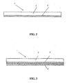
- FIG. 2 is a cross-sectional view of an insulated beverage container wall or sleeve according to a reference example
- FIG. 3 is a cross-sectional view of an insulated beverage container wall according to a first embodiment of the present invention
- FIG. 4 is a cross-sectional view of an insulated beverage container wall according to a second embodiment of the present invention.
- FIG. 5 is a cross-sectional view of an insulated beverage container wall according to a third embodiment of the present invention
- FIG. 6 is a cross-sectional view of an insulated beverage container wall according to a reference example
- FIG. 7 is a graphical view of experimental data representing actual and comparative hold times for embodiments of the present invention and commercial available products;
- FIG. 8 is a cross sectional view of an insulating beverage container sleeve according to the present invention.
- FIG. 9 is a cross-sectional view of an insulated beverage container wall or beverage container sleeve wall according to a fifth embodiment of the present invention.
- FIG. 10 is a plan view depicting an interior and exterior of a beverage container or sleeve wall according to the present invention.
- FIG. 11 is a plan view depicting an interior and exterior of a beverage container or sleeve wall according to the present invention.
- the present invention is directed toward an insulated beverage or food container, cup or sleeve; the container stock material; and a method of producing insulated beverage or food containers or stock materials that utilize a polyethylene foam layer extruded or laminated to a surface of a food or beverage paper stock.
- the present invention is described in greater detail hereinafter with reference to the accompanying drawings.
- FIGs. 2 through 6 are cross-sectional views of an insulated beverage container wall 11 according to various embodiments.
- an insulated container 10 as shown in FIG. 1 can readily incorporate any of the beverage container walls depicted in FIGs. 2 through FIG. 6. While the following description is directed toward a cup, the techniques of this invention can be applied to any number of containers or surfaces, for instance a beverage container, insulating beverage sleeve or stock material can be constructed from any of the embodiments shown in the accompanying drawings.
- FIG. 1 is a side cross-sectional view of an insulated beverage container 10 according to the present invention.
- the insulated beverage container includes a container wall I having an upper side portion 7, a lower side portion 8 and a bottom portion 9.
- a beverage containing space 11 is formed between the container wall's 1 upper side portion 7, lower side portion 8 and bottom portion 9.
- the present invention utilizes a gas containing film adhered or selectively adhered to the surface of a paper stock.
- the gas containing film layer provides resistance to heat transfer through the container wall 1.
- the present invention provides an insulating container construction and a method of producing this construction which reduces the energy transfer through the container wall, providing increased functionality and usefulness.
- FIG. 2 is a cross-sectional view of an insulated beverage container wall or sleeve 1.
- a beverage container wall or sleeve 1 includes a paper stock 2, and an extruded or laminated foam layer 3.
- the paper stock 2 provides structural rigidity and forms the desired shape of the container 10 or a portion of a sleeve wall.
- the extruded or laminated foam layer 3 is adhered to an inner surface (e.g., facing the beverage containing space 11) of the paper stock 2 and performs the function of a gas containing film layer.
- the foam layer 3 is designed to provide thermal insulation properties to the container.
- the paper stock 2 is standard paper used for making beverage cups and other food containers.
- the paper stock 2 may be chosen with a thickness that provides optimized physical characteristics for cup construction. Important physical characteristics include fold strength, stiffness, tear and tensile strength.
- a desired paper thickness is chosen such that the resultant thickness of the finished cup wall 1 does not negatively impact converting, handling or finished cup properties.
- a typical paper stock 2 for beverage and food containers range from 10 to 40 mils in a paper stock 2 thickness, and more particularly from 10 mils to 26 mils in thickness.
- the paper stock 2 may be chosen with a thickness which provides the proper physical characteristics such as strength for constructing a sleeve surrounding a beverage container 10 such as that shown in FIG. 1.
- Paper thickness is chosen such that the resultant thickness of the sleeve and cup wall does not negatively impact handling, distribution or become cumbersome to the end user. Additional criteria affecting paper stock selection includes appearance and cost.
- a smooth, bleached-white paper may be chosen to enhance the print quality and the appeal of the cup, or a brown kraft stock may be chosen for economy.
- Applicable paper suitable for sleeve stock ranges from 2 mils to 10 mils for the application to an insulating beverage sleeve.
- the extruded or laminated foam layer 3 is applied to the paper stock 2 as an extrusion or lamination.
- the purpose of the extruded or laminated foam layer 3 is to provide thermal insulation properties, and to contain liquids.
- the extruded or laminated foam layer 3 can also be used as a barrier to moisture transmission and further aids in seam sealing during container construction.
- the foam layer 3 is a gas containing layer that provides resistance to heat transfer through the sleeve wall.
- the extruded or laminated foam layer 3 can be formed from any of the following exemplary materials: high density polyethylene (HDPE), low density polyethylene (LDPE), linear low density polyethylene (LLDPE), orientated polypropylene (OPP), etc.
- HDPE and LDPE are desirable materials.
- additional foam polymers may include and/or be formed from PEFSs, LDPEs or HDPEs that are not tensioned or stretched during manufacturing.
- Additives may also be included to enhance various material properties or to aid in the manufacturing process. These additives include, but are not limited to, any of the following exemplary additives: ethylene vinyl acetate (EVA), ethylene vinyl alcohol (EVOH), and plasticizers.
- EVA ethylene vinyl acetate
- EVOH ethylene vinyl alcohol
- plasticizers plasticizers
- the foam layer 3 is attached to the paper stock uniformly during the manufacturing process.
- the gases trapped within the film of the foam layer 3 impart a high level of thermal insulation to the container wall.
- An important aspect of the gas containing foam layer 3 is to provide resistance to energy transfer. The amount of trapped gas is variable and depends upon a specified volume that will render the exterior of the container comfortable to hold for an average user. Therefore, the required amount of trapped air will generally vary according to the intended use of the container.
- a container used to serve coffee (normally 88°C (190° F)) will need more resistance to energy flow than a similar container used to serve a relatively cool cup of soup (normally 74°C (165° F)).
- An additional benefit to the insulating layer is the ability of the container to keep the food or beverage at its serving temperature for a longer period of time.
- a foam layer 3 can be either laminated to or extruded onto the paper stock 2.
- a gas containing film such as CA-20 manufactured by Sealed Air Corporation or another may be used.
- a blowing agent is mixed into the polymer prior to extrusion. The incorporated blowing agent creates gas pockets within the film during the extruding process.
- the extrusion method offers the additional advantage of creating the product in one operational step.
- the insulating foam layer 3 is preferably between 3 and 44 g/m 2 (2 and 30 lbs/3300 ft 2 ), and more preferably between 7 and 22 g/m 2 (5 and 15 lbs/ 3300 ft 2 ).
- the density of the film is preferably between 16 and 48 kg/m 3 (1.0 and 3.0 lbs/ft 3 ).
- the thickness of the insulating gas containing foam layer 3 is preferably between 127 and 762 ⁇ m (5 and 30 mils), and more preferably between 254 and 508 ⁇ m (10 and 20 mils).
- the foam layer 3 can be a gas containing film layer formed from a continuous single layer or lamination of films and foam.
- FIG. 3 is a cross sectional view of a container wall according to a first embodiment of the present invention.
- a polymer shrink film layer 4 is extruded, laminated, or coated to the foam containing layer 3, e.g. in a position between the beverage containing space 11 and the foam containing layer 3 in a container 10.
- the foam layer 3 is therefore interposed between the paper stock 2 and the polymer shrink film layer 4.
- the polymer shrink film layer 4 will hereinafter be referred to as a PE layer 4.
- the PE layer 4 can be used as a barrier against moisture transmission and aids in seam sealing during container construction.
- the foam layer 3 is first formed and then it is melt extruded, laminated or melt fused to the surface of the paper stock 2.
- the residual moisture held within the paper stock 2 which is characteristically relied upon in the related art, is not relied upon as the mechanism for creating the foam layer 3.
- the foam can also be extruded to the paper stock 2, but in each instance the foaming is created by mixing a blowing agent into the polymer prior to extrusion or foam creation.
- the incorporated blowing agent creates gas pockets within the film during the extruding process.
- the extruded method offers the advantage of directly creating the product in one operational step.
- the foam layer 3 can also be treated in order to accept or conform with various printing inks.
- the foam layer 3 can be treated by various means well known in the industry such as, but not limited to: corona treatment, flame treatment, ozone treatment, coatings, etc.
- FIG. 4 is a cross sectional view of a container wall according to a second embodiment of the present invention.
- a PE layer 4 is extruded, laminated, or coated in a position interposed between the foam layer 3 and the paper stock 2.
- PE layer 4 can also be used as a barrier against moisture transmission and aids in seam sealing during container construction.
- the foam layer 3 can also be sandwiched between two PE layers 4, e.g. an innermost PE layer is adhered directly to the paper stock layer 2 in a third embodiment.
- the PE layer(s) can be formed from any of the following exemplary materials: high density polyethylene. (HDPE), low density polyethylene (LDPE), linear low density polyethylene (LLDPE), orientated polypropylene (OPP), etc.
- HDPE and LDPE are desirable materials in. a. preferred embodiment of the present invention.
- Some additional and applicable shrinkable thermoplastics are PVC, PTEE, FEP, PVDF, PET, LDPE, LLDPE, HDPE and polyolefin, that may be readily incorporated into the claimed invention.
- the PE layer(s) 4 can be manufactured to develop a property called shape memory.
- shape memory causes the PE layer(s) to shrink, e.g. the polymer molecules relax to their original shape, when reheated.
- the present inventors have determined that the shape memory of particular PE layer(s) can be used advantageously in conjunction with paper stock materials to produce polymer shrink film layers 4 that reduce and/or eliminate a wrinkling effect discussed in greater detail hereinafter.
- Additives may also be included to enhance various material properties or to aid in the manufacturing process. These additives include, but are not limited to, any of the following exemplary additives: ethylene vinyl acetate (EVA), ethylene vinyl alcohol (EVOH), and plasticizers.
- EVA ethylene vinyl acetate
- EVOH ethylene vinyl alcohol
- plasticizers plasticizers
- FIG. 6 is a cross sectional view of a container wall according to a fourth embodiment of the present invention.
- a PE layer 4 has been applied to an outside surface or interior surface, e.g. a surface opposite to the foam layer 3 with respect to the paper stock 2.
- the PE layer 4 can be laminated, extruded or coated onto the paper stock surface.
- the PE layer 4 also serves a barrier to the beverage or food placed within the container, and can also serve as a sealing mechanism.
- the PE layer 4 could be applied as the innermost layer, e.g., closest to the beverage containing space 11.
- PE layers 4 and/or foam layers 3 can be applied to either the inside or outside surfaces of the container wall 1 as desired to add additional barriers and/or thermal resistance to the liquid or heat sealed within (or excluded from) the container.
- the PE layer 4 can be applied directly to the paper stock 2 or indirectly over the foam 3.
- a preferred coating material for additional coating layers for the present invention is an expanding foam.
- This expanding foam material is encapsulated isobutane in a polymeric shell.
- the expanding foam capsules are added to the coating with a small, e.g., unexpanded, diameter.
- the encapsulated isobutane changes from a liquid to a gas and the polymeric shell expands with the appropriate volumetric change.
- Expanded foam also has the advantage of creating a rough surface that will further reduce the contact area between layers in the container wall and therefore reduce heat transfer.
- a thin layer of the expanding foam coated onto the paper stock exterior is especially useful for roughening or for texturing to aid in gripping the container.
- a preferred coating is a foamed coating.
- Foamed coating is a coating that utilizes entrained air. The dispersed air in the coating provides a low coating density and low thermal conductivity. The foamed coating also accepts and is easily processed to achieve surface modification. The foamed coating will therefore allow a rough or perforated surface to be created through the use of an embosser, press or other mechanical device.
- Foam coating also has the ability to be used as a single coating, or may also act as the insulating coating and a printing coating simultaneously, depending on the application and desires of the end user.
- the selected coating materials for the insulating coating are dispersed in an aqueous system with additional components added as necessary to provide ease of processing and application.
- Pigments such as silica, calcium carbonate, clay and synthetic pigments may be also used.
- Binders are included to adhere the coating to the paper substrate.
- Typical binders may be selected from, but are not limited to, polyvinyl alcohol, SBR latex, starch, polyacrylates and other binders well known in the related art.
- Other additives may be included in the coating to aid in dispersion, rheology and coating handling. These additives include, but are not limited to, defoamers, dispersants, wetting agents, conductive polymers, styrene malefic anhydride, thickeners, etc.
- An insulating coating can be applied that is between 3 and 44 g/m 2 (2 and 30 lbs / 3300 ft 2 ), and more preferably between 7 and 22 g/m 2 (5 and 15 lbs / 3300 ft 2 ).
- a preferred thickness of the insulating coating is between (1 and 15 mils), most preferably between 76 and 254 ⁇ m (3 and 10 mils).
- the preferred embodiments depicted in the accompanying figures are directed toward the application of a foam layer 3 toward or along the interior surface of a container (e.g., beverage-side of the container).
- a container e.g., beverage-side of the container.
- the foam layer 3 can be alternatively, or in combination with the PE film layer 4, applied along the exterior surface of the container.
- a beverage container 10 constructed with a container wall 1 having the construction shown in FIG. 3 has demonstrated extraordinary hold times, moisture inhibition and resistance to vapor transmission. Further, the inventors of the present invention have demonstrated that hold times are significantly increased with the embodiment shown in FIG. 3 as compared to providing a moisture foam layer 3 blown on the outside surface of the paper stock 2, such as the PerfecTouchTM cup sold by Georgia PacificTM.
- hold time a quantitative measurement of the ability of a paper stock to withstand heat transfer between the beverage containing space and the outermost surface of the container. Accordingly, how long one can comfortably hold the hot container 10, e.g., hold time, is significantly reduced.
- the preferred embodiment shown in FIG. 3 appears to best inhibit heat transfer to the paper stock 2, thereby reducing heat transfer by providing a moisture vapor transmission barrier at the innermost surface which prevents heating by mass transfer of that vapor through the cupstock. Hold times were significantly increased with the preferred embodiments of the present invention.
- FIG. 7 is a graphical view of experimental data representing actual and comparative hold times for embodiments of the present invention and commercial available products and will be discussed further hereinafter.
- FIG. 8 is a cross sectional view of an insulating beverage container sleeve 12 according to the present invention.
- FIG. 8 is a cross-sectional view of an insulated beverage container wall 1 or beverage container sleeve wall 1 according to another embodiment of the present invention.
- an insulating beverage container sleeve 12 can readily incorporate any of the applicable embodiments of beverage container stock material (container wall) 1 shown in the accompanying drawings.
- An insulating beverage container sleeve 12 is often slipped over the outer surface of a beverage container such as that shown in FIG. 1.
- an intermediate layer 5 may be provided between the paper stock 2 and foam layer 3.
- the intermediate layer 5 is applied to the paper stock as an extrusion, lamination, or coating.
- the purpose of the intermediate layer 5 is to adhere the gas containing film layer 3 to the paper stock 2.
- intermediate layer 5 can also be utilized as a barrier to moisture transmission and as an aid in seam sealing during sleeve construction.
- Typical materials used for intermediate layer 5 include, but are not limited to: high density polyethylene (HDPE), low density polyethylene (LDPE), linear low density polyethylene (LLDP), orientated polypropylene(OPP); and adhesives, such as hot melt adhesives, water based adhesives and solvent based adhesives, etc.
- Additives known in the industry may be included to enhance certain properties or aid in processing and may include, but are not limited to: ethylene vinyl acetate (EVA), ethylene vinyl alcohol (EVOH), and plasticizers.
- Exterior layer 4 is applied to the paper stock to provide a surface which may have the following properties depending on end use, including but not limited to: materials accepting high quality graphics and printing inks, materials providing tactile feel, materials that change color with temperature, materials providing seam sealing capabilities, and materials providing a more secure gripping surface, etc.
- the sleeve 12 construction may be preferentially oriented with the foam material 3 toward the cup 11 surface and the paper surface 2, 4 facing outward, e.g., visible to the user.
- the sleeve construction can be inverted with the foam on the exterior and the paper surface(s) 2, 4 facing inwardly toward the cup/container 11 wall.
- a PE layer as aforementioned can also be applied (not shown in FIG. 9) along the interior surface of the container, e.g. between the foam layer 3 and the beverage containing space 11 when the embodiment of FIG. 9 is applied to a container 10.
- FIG. 7 is a graphical view of experimental data representing actual and comparative hold times for embodiments of the present invention and commercial available products.
- FIG. 7 shows experimental hold times (measured in seconds) achieved for different samples.
- the various samples or beverage containers were filled with approximately 230 ml of water at approximately 90 ° C (194 ° F pour temperature).
- Sample S2 is a product/container sample having 15/15/15 pt base stock/air w/corrugation/base stock.
- Sample S5, Sample S6, and Sample S7 are test samples of the present invention incorporating a container wall 1 with construction similar to that shown in Fig. 3.
- Sample S5 is a 10 pt foam 18 pt base paper laminate.
- S6 is a 20 point foam 18 pt base paper laminate.
- S7 is a 30 pt foam 18 pt base paper laminate.
- Sample S9 is a paper stock with a moisture blow polyethylene exterior such as the PerfecTouch TM container available from .Fort James.
- Sample S12 is a laminate foam 18 pt base with 20 pt polyethylene foam.
- Testing was conducted of different samples to determine average hold times after several iterations of testing.
- a control test person was used in many testing results to maintain data integrity. In alternative testing, several different control test persons were utilized.
- Table I provides experimental test results of insulated cup hold time studies conducted at a pour temperature of 90 °C and with approximately 230 ml of water. Table I is directed toward the test results of the various samples.
- Paper stock-based laminates may suffer from wrinkling or creasing of the innermost layers of a final product after manufacture.
- a beverage container 11 or sleeve 12 utilizing a foam layer.3 along the interior may experience a particularly problematic wrinkling effect.
- the cup diameter will vary depending on the substrate thickness or caliper of each layer of the laminate, the number of layers and the type of materials utilized in each layer.
- the diameter will also vary depending on where it is measured, e.g. the diameter along the upper side surface. 7 is greater than that along the lower side surface 8.
- the thicker the substrate the greater the difference between the innermost and outermost diameters. Since both surfaces of the substrate start out at the same length, the difference in diameter creates a system that is under stress.
- the cup forming substrate such as a paper stock 2
- a foam layer 3 along the interior surface is relatively soft and pliable. Therefore, the foam properties along the interior surface, coupled with the change in diameter, cause wrinkles to form under the stress (with less ability to withstand the stress) of conforming to a relatively smaller diameter.
- the cross-section shown in FIG. 3 is exemplary of a container 10 having a PE layer 4, wherein the foam layer 3 is sandwiched in between the paper stock layer 2 and the PE layer 4.
- the cross-section shown in FIG. 4 is exemplary of an insulating foam layer 3 adhered to the paperboard stock layer 2 by a PE layer 4 that may exhibit the aforementioned wrinkling effect.
- another embodiment includes at least two PE layers 4, wherein an inner surface of the container employing this cross section will also have a PE layer 4 closest to the beverage container space 11.
- FIG. 10 is a plan view depicting an interior and exterior of a beverage container or sleeve wall according to another embodiment of the present invention.
- FIG. 11 is a plan view depicting an interior and exterior of a beverage container or sleeve wall according to another embodiment of the present invention.
- FIGs. 10-11 are also directed toward a method of making a beverage container or sleeve that eliminates or substantially reduces the amount of wrinkling occurring along a container's interior 30.
- FIGs. 10 and 11 depict the interior cup surface 30 and exterior cup surface 40 of a container before and after heating and shrinking the polymer shrink film layer (PE layer) 4, respectively, according to an embodiment of the present invention.
- the foam layer 3 has wrinkled under the stresses of conforming to a smaller diameter. After being subjected to a heating process, the foam shrinks, producing a taut, smooth layer as shown in FIG. 11.
- die cut paper may be wrapped around a mandrel to form the container cylinder. Due to the relative change in diameter, the inner surface 30 is now under stress.
- the wrinkles can be removed through the application of heat.
- a formed cup with a wrinkled interior can be exposed to heat, causing the foam to shrink and remove the wrinkles 20.
- the specific details of the heat application method are not critical. In an ideal embodiment, the heating method and/or equipment can be incorporated into existing cup making equipment.
- the heating process can include localized heating or shrinking processes, e.g., only the interior surface is subjected to a heating process, such as heated process air being passed exclusively along the interior surface 30.
- a heating process such as heated process air being passed exclusively along the interior surface 30.
- the entire container or various ratios of controlled heating may be employed, e.g., interior surface heating rate to exterior surface heating rate being increased so that an interior to exterior ratio is generally higher than 1:1.
- the elimination of wrinkles 20 can be accomplished with any combination of heating and/or the incorporation of polymers for the foam layer 3 and polymer shrink film layer 4 having desirable heat shrink properties.
- the air used to transport and stack the finished cups can be heating, the forming mandrels can be heated, the cup can be transported through a tunnel heater or other heating device, and/or a heated air stream can be passed across the cup's interior surface 30.
- Shrink films can be made out of a wide range of commercially available polymers. Table II lists some applicable shrink-films commercially available in the United States. However, one of skill in the art will appreciate that other commercially available films are available or are currently being developed. Accordingly, any shrink film having desirable shrink film properties for the present invention is within the spirit and scope of the present invention.
- the polymers chosen and the polymer processing history are two major factors influencing the foam shrink properties. The polymer type and processing method should be selected to create the amount of shrinkage necessary while maintaining foam integrity.
- the Wiley Encyclopedia of Packaging Technology, Second Edition, Aaron L. Brody and Kenneth S. Marsh, John Wiley and Sons, 1997 describes additional examples of suitable shrink films and their related properties.
- Preferred shrink films for the present invention are determined by their properties and cost.
- Specific examples of shrink films for the foam layer 3 of the present invention are high density polyethylene or blends of HDPE and linear low density polyethylene (LLDPE), e.g., not more than 30% by weight.
- the shrink films are created by stretching the warm film and keeping it under tension while cooling. The polymer chains are then locked into a stressed state. Upon being subjected to a heating process near the melting point of the shrink film, the chains relax and the film shrinks.
- required "percent shrink” is low relative to shrink films commercially marketed under this category.
- Typical shrink films will shrink on the order of 70-80% if unrestrained.
- the present inventors have determined that too much shrinkage of the foam layer 3 will cause the film to pull away from the container wall 11 and/or delaminate. Further, too much shrinkage will result in undesired interior cup space loss and reduced stacking efficiencies.
- the present inventors have determined that a foam layer 3 having a percent shrink of between 5-30%, and more preferably a percent shrink of 5-10%, will create the best results. Films with higher shrinkage rates may be used if additional considerations are taken to control the shrinkage of the container, such as controlling shrinkage through the use of an inserted mandrel or other physically limiting device.
- the shrink initiation temperature is another key attribute of a preferred shrink film.
- a shrink film can be designed to shrink at 88°C (190 ° F), such as when hot coffee is poured into a container thereby causing wrinkles 20 to be pulled or smoothed out under tension.
- a shrink film can be selected that shrinks at a temperature well above 88°C (190 ° F), such as during a relatively high manufacturing process temperature so that wrinkles are removed prior to the actual use of the container. If the initiation temperature is low, the total amount of shrinkage must also be low. For example, if the initiation temperature is 88°C (190 ° F), and 93°C (200 ° F) coffee is poured into the cup, the shrinkage must be low to avoid cup volume loss and expulsion of hot coffee as the volume decreases.
- a method of producing an insulated container may include the steps of providing a paper cupstock having a container wall 1 for surrounding an interior space 11, a bottom portion 9, and a paper stock layer 2 arranged along an exterior surface 40 of the container wall 1; mixing a blowing agent into a foamable polymer layer 3; forming a foam layer 3 along an inside surface 30 of the interior space 11; adhering a polymer shrink film layer 4, e.g., PE layer 4, to the foam layer 3; and heat treating the container to shrink the polymer shrink film layer between a percent shrink range of 30% or less.
- the foam layer 3 is adhered to the paper cupstock 2, either directly or indirectly through another intermediate layer 5, e.g. such as an additional PE layer 4.
- the aforementioned method of producing an insulated food or beverage container or sleeve may also include the steps of providing an insulated container or sleeve having an interior space 11, the interior space 11 including a polymer shrink film layer 4 and a foam layer 4 along an interior surface 30 thereof.
- the interior surface 30 is heated to shrink the polymer shrink film layer 20 and remove wrinkles along the foam layer(s) 3 and polymer shrink film layer(s) 4 during the heating step to thereby prevent an undesirable wrinkling effect in the interior space 30.
- the heat treatment process is employed either during the manufacturing process or during product use, e.g., hot cup of coffee produces desired shrinkage for shrinking the foam layer to remove wrinkles at a percent shrink range of 5-30%.
- the heat treatment process may also be any conventional heat treatment process for shrinking polymer shrink films available in the related art. This includes both heating and cooling processes, including combinations thereof.
- the Wiley Encyclopedia of Packaging Technology Second Edition, Aaron L. Brody and Kenneth S. Marsh, John Wiley and Sons, 1997, describes specific examples of heat treatment processes for implementing shrink films.
- the present invention may utilize conventional heat treatment processes such as a tenter-frame process, a bubble process, combinations thereof and/or their equivalents.
Abstract
Description
- The present invention relates to insulating containers and container stock material. In particular, the present invention relates to an insulated, paper-based beverage or food container or stock material having improved insulation properties and a method of producing these insulated containers or stock materials.
- Current standard paper cup stock permits excessive heat transfer through the wall of an insulated beverage container. Accordingly, a user's hand becomes uncomfortably or sometimes even painfully hot when excessive heat transfer is permitted through the container wall. This may require the user to be inconvenienced by having to release the container due to the excessive heat of the container's contents. Thus, such containers have a low hold time. An analogous but opposite situation can occur with very cold beverages, where heat from a user's hand is transferred rapidly to the contents of the container.
- US-A-4435344 describes a method for producing an insulating composite paper container having a body member and a bottom member. The body member is formed of paper coated or laminated with a thermoplastic synthetic resin film. A surface of the body member is then heated to form a foamed polyethylene heat-insulating layer on either or both of the inner and outer surfaces of the container's body member. The heat-insulated body member is then attached to the bottom member.
- US-A-6030476 and US-A-5840139 describe a method for producing insulating beverage containers or cups, stock material and containers made therefrom. A stock material includes a base layer, an insulating layer formed on a portion of the base layer, and a printed pattern/mineral oil applied to the insulating layer. The insulating layer is formed using a thermoplastic synthetic resin film. Also, US-A-6030476 describes a polyethylene foam on the outside surface of the paper cup.
- EP-A-0940240 describes a heat insulating paper cup with targeted insulation in areas where printed matter exists. The body member of the cup is coated on its outside surface with a foamable synthetic resin and on its inside surface with a synthetic resin laminate to prevent liquid penetration. The bottom panel member is optionally coated on its upper surface with a foamed or an unfoamed synthetic resin. Printed matter is provided prior to foaming of the synthetic resin on the outer surface of the cup with water-based ink. Further, the low density polyethylene is foamed by vaporizing the water contained in the paper stock.
- EP-A-1060879 describes a heat insulating paper cup having a body member partially or fully coated on its outside surface with a foamed low density polyethylene and coated on its inside surface with an unfoamed modified low density polyethyelene.
- US-A-5952068 describes a heat insulating paper cup having a layer of insulation comprised of void containing particles held together with a binder applied to the outer part of the sidewall. The insulating layer may be bonded to the outside surface of the paper cup stock by means of a polymer tie layer.
- JP-A-2000335548 describes a heat insulating paper cup formed from a composite sheet comprising a layer of foamed insulating material sandwiched between two layers of paper. A polyethylene resin protective layer is provided on the inside surface of the cup.
- However, the present inventors have determined that the devices and methods of the background art suffer from the following disadvantages. Other designs sacrifice the outside printability of the cup to provide insulation or do not provide adequate insulation properties.
- The background art has not yet achieved insulated paper stock that is capable of effectively impeding heat transfer between the contents of the container and the exterior. In addition, adequate thermal insulation is not achieved from the background art in a manner that is cost effective.
- The present invention overcomes the shortcomings associated with conventional devices and methods, and achieves other advantages not realized by conventional devices and methods.
- It is an object of the present invention to provide an insulated beverage container, sleeve or stock material that reduces the energy transfer through a container wall, and offers increased functionality and usefulness.
- It is an object of the present invention to provide a container, sleeve, or stock material having superior hold times and pre-disposed to high quality printing and graphics.
- The present invention is a recognition, in part, that the ability to produce blank paper cups, sleeves or stock material that can be printed/graphically enhanced is desirable. This invention permits a superior insulating cup product to be made from standardized manufacturing processes.
- In a first aspect, the present invention provides an insulated container comprising: a container wall having an exterior surface and an interior surface; a bottom portion engaging said container wall along a lower side portion thereof; said container wall comprising: a paper stock layer arranged along the exterior surface of said container wall; an extruded or laminated foam layer arranged inside said paper stock layer; and a polymer shrink film layer arranged inside said paper stock layer,said polymer shrink film layer having a percent shrink of from 5 to 30%.
- Preferably, the foam layer is sandwiched between said paper stock layer and said polymer shrink film layer, and preferably the polymer shrink film layer forms the innermost surface of said container wall. In certain embodiments, the container wall further comprises an additional polymer film layer inside said paper stock layer, said foam layer being sandwiched between said additional polymer film layer and said polymer shrink film layer.
- Suitably, the paper stock layer has a thickness greater than or equal to 254 µm (10 mils) and less than or equal to 660 µm (26 mils).
- Suitably, the foam layer is formed from at least one of high density polyethylene, low density polyethylene, linear low density polyethylene, and oriented polypropylene. Suitably, the polymer shrink film layer is a laminated or extruded shrink film polymer formed from at least one of high density polyethylene, low density polyethylene, linear low density polyethylene, and oriented polypropylene.
- Suitably, the foam layer is adhered to the paper stock layer by melt extrusion, lamination or foam extrusion.
- In a second aspect, the present invention provides an insulated food or beverage container sleeve comprising: a paper stock layer having an interior surface; a laminated or extruded foam layer, said foam layer being disposed along the interior surface of the paper stock layer; and a polymer shrink film layer having a percent shrink of from 5 to 30%, the foam layer being sandwiched between the paper stock layer and the polymer shrink film layer.
- Preferably, the sleeve further comprises an additional polymer film layer sandwiched between the paper stock layer and said foam layer.
- In a further aspect, the present invention provides an insulated container stock material for making an insulated container or an insulated sleeve according to the present invention, said stock material comprising: a paper stock layer; a laminated or extruded foam layer formed from high density polyethylene, low density polyethylene, linear low density polyethylene, or oriented polypropylene, said foam layer being arranged along a first surface the paper stock layer; and a polymer shrink film layer having a percent shrink of from 5 to 30% and also arranged said first surface of said paper stock layer.
- Preferred features of the invention according to this aspect are as described hereinbefore in relation to the first aspect of the invention
- In a further aspect, the present invention provides a method of producing an insulated food or beverage container or sleeve, comprising the steps of: providing an insulated container or sleeve having a wall defining an interior space, said wall having arranged along an interior surface thereof a polymer shrink film layer having a percent shrink of from 5 to 30% and a laminated or extruded foam layer; heating the interior surface to shrink the polymer film layer; and removing wrinkles along the foam and polymer shrink film layers during the heating step to thereby prevent a wrinkling effect in the interior space.
- Suitably, in the method according to this aspect of the invention, the heating step includes at least one of heating a supply of air for transporting and stacking the food or beverage container, heating a forming mandrel for the food or beverage container, and transporting the food or beverage container through a tunnel heater.
- Suitably, the step of providing comprises forming a food or beverage container or sleeve from an insulated container stock material according to the present invention.
- Further scope of the applicability of the present invention will become apparent from the detailed description given hereinafter. However, it should be understood that the detailed description and specific examples, while indicating preferred embodiments of the invention, are given by way of illustration only, since various changes and modifications within the scope of the invention will become apparent to those skilled in the art from this detailed description.
- The present invention will become more fully understood from the detailed description given hereinafter and the accompanying drawings which are given by way of illustration only, and thus are not limitative of the present invention, and wherein:
- FIG. 1 is a side cross-sectional view of an insulated beverage or food container according to the present invention;
- FIG. 2 is a cross-sectional view of an insulated beverage container wall or sleeve according to a reference example;
- FIG. 3 is a cross-sectional view of an insulated beverage container wall according to a first embodiment of the present invention;
- FIG. 4 is a cross-sectional view of an insulated beverage container wall according to a second embodiment of the present invention;
- FIG. 5 is a cross-sectional view of an insulated beverage container wall according to a third embodiment of the present invention
- FIG. 6 is a cross-sectional view of an insulated beverage container wall according to a reference example;
- FIG. 7 is a graphical view of experimental data representing actual and comparative hold times for embodiments of the present invention and commercial available products;
- FIG. 8 is a cross sectional view of an insulating beverage container sleeve according to the present invention;
- FIG. 9 is a cross-sectional view of an insulated beverage container wall or beverage container sleeve wall according to a fifth embodiment of the present invention;
- FIG. 10 is a plan view depicting an interior and exterior of a beverage container or sleeve wall according to the present invention; and
- FIG. 11 is a plan view depicting an interior and exterior of a beverage container or sleeve wall according to the present invention.
- The present invention is directed toward an insulated beverage or food container, cup or sleeve; the container stock material; and a method of producing insulated beverage or food containers or stock materials that utilize a polyethylene foam layer extruded or laminated to a surface of a food or beverage paper stock. The present invention is described in greater detail hereinafter with reference to the accompanying drawings.
- FIGs. 2 through 6 are cross-sectional views of an insulated beverage container wall 11 according to various embodiments. One of skill in the art will appreciate that an
insulated container 10 as shown in FIG. 1 can readily incorporate any of the beverage container walls depicted in FIGs. 2 through FIG. 6. While the following description is directed toward a cup, the techniques of this invention can be applied to any number of containers or surfaces, for instance a beverage container, insulating beverage sleeve or stock material can be constructed from any of the embodiments shown in the accompanying drawings. - FIG. 1 is a side cross-sectional view of an
insulated beverage container 10 according to the present invention. The insulated beverage container includes a container wall I having anupper side portion 7, alower side portion 8 and abottom portion 9. A beverage containing space 11 is formed between the container wall's 1upper side portion 7,lower side portion 8 andbottom portion 9. - As aforementioned, current standard paper cup stock allows excessive heat to transfer through the wall of the container. This results in a user's hand becoming uncomfortably or sometimes even painfully hot or cold when grasping a hot or cold container. A quantitative measurement of the ability of a paper stock to withstand heat transfer between the beverage containing space and the outermost surface of the container is often referred to as hold time. It will be appreciated that the present invention significantly improves the hold time of paper-based stock beverage containers over the related art.
- The present invention utilizes a gas containing film adhered or selectively adhered to the surface of a paper stock. The gas containing film layer provides resistance to heat transfer through the
container wall 1. The present invention provides an insulating container construction and a method of producing this construction which reduces the energy transfer through the container wall, providing increased functionality and usefulness. - FIG. 2 is a cross-sectional view of an insulated beverage container wall or
sleeve 1. A beverage container wall orsleeve 1 includes apaper stock 2, and an extruded orlaminated foam layer 3. Thepaper stock 2 provides structural rigidity and forms the desired shape of thecontainer 10 or a portion of a sleeve wall. The extruded orlaminated foam layer 3 is adhered to an inner surface (e.g., facing the beverage containing space 11) of thepaper stock 2 and performs the function of a gas containing film layer. Thefoam layer 3 is designed to provide thermal insulation properties to the container. - The
paper stock 2 is standard paper used for making beverage cups and other food containers. Thepaper stock 2 may be chosen with a thickness that provides optimized physical characteristics for cup construction. Important physical characteristics include fold strength, stiffness, tear and tensile strength. - A desired paper thickness is chosen such that the resultant thickness of the
finished cup wall 1 does not negatively impact converting, handling or finished cup properties. Atypical paper stock 2 for beverage and food containers range from 10 to 40 mils in apaper stock 2 thickness, and more particularly from 10 mils to 26 mils in thickness. Where the material is applied to an insulating beverage sleeve, thepaper stock 2 may be chosen with a thickness which provides the proper physical characteristics such as strength for constructing a sleeve surrounding abeverage container 10 such as that shown in FIG. 1. - Important physical characteristics include fold strength, stiffness, tear and tensile strength. The paper thickness is chosen such that the resultant thickness of the sleeve and cup wall does not negatively impact handling, distribution or become cumbersome to the end user. Additional criteria affecting paper stock selection includes appearance and cost. A smooth, bleached-white paper may be chosen to enhance the print quality and the appeal of the cup, or a brown kraft stock may be chosen for economy. Applicable paper suitable for sleeve stock ranges from 2 mils to 10 mils for the application to an insulating beverage sleeve.
- The extruded or
laminated foam layer 3 is applied to thepaper stock 2 as an extrusion or lamination. The purpose of the extruded orlaminated foam layer 3 is to provide thermal insulation properties, and to contain liquids. The extruded orlaminated foam layer 3 can also be used as a barrier to moisture transmission and further aids in seam sealing during container construction. In the case of an insulating beverage sleeve, thefoam layer 3 is a gas containing layer that provides resistance to heat transfer through the sleeve wall. - The extruded or
laminated foam layer 3, although not limited to, can be formed from any of the following exemplary materials: high density polyethylene (HDPE), low density polyethylene (LDPE), linear low density polyethylene (LLDPE), orientated polypropylene (OPP), etc. HDPE and LDPE are desirable materials. Although not necessary, additional foam polymers may include and/or be formed from PEFSs, LDPEs or HDPEs that are not tensioned or stretched during manufacturing. - Additives may also be included to enhance various material properties or to aid in the manufacturing process. These additives include, but are not limited to, any of the following exemplary additives: ethylene vinyl acetate (EVA), ethylene vinyl alcohol (EVOH), and plasticizers.
- The
foam layer 3 is attached to the paper stock uniformly during the manufacturing process. The gases trapped within the film of thefoam layer 3 impart a high level of thermal insulation to the container wall. An important aspect of the gas containingfoam layer 3 is to provide resistance to energy transfer. The amount of trapped gas is variable and depends upon a specified volume that will render the exterior of the container comfortable to hold for an average user. Therefore, the required amount of trapped air will generally vary according to the intended use of the container. - For instance, a container used to serve coffee (normally 88°C (190° F)) will need more resistance to energy flow than a similar container used to serve a relatively cool cup of soup (normally 74°C (165° F)). An additional benefit to the insulating layer is the ability of the container to keep the food or beverage at its serving temperature for a longer period of time.
- A
foam layer 3 can be either laminated to or extruded onto thepaper stock 2. When thefoam layer 3 is laminated to thepaper stock layer 2, a gas containing film such as CA-20 manufactured by Sealed Air Corporation or another may be used. When the film is extruded onto the paper stock 2 a blowing agent is mixed into the polymer prior to extrusion. The incorporated blowing agent creates gas pockets within the film during the extruding process. The extrusion method offers the additional advantage of creating the product in one operational step. - The insulating
foam layer 3 is preferably between 3 and 44 g/m2 (2 and 30 lbs/3300 ft2), and more preferably between 7 and 22 g/m2 (5 and 15 lbs/ 3300 ft2). The density of the film is preferably between 16 and 48 kg/m3 (1.0 and 3.0 lbs/ft3). The thickness of the insulating gas containingfoam layer 3 is preferably between 127 and 762 µm (5 and 30 mils), and more preferably between 254 and 508 µm (10 and 20 mils). Thefoam layer 3 can be a gas containing film layer formed from a continuous single layer or lamination of films and foam. - FIG. 3 is a cross sectional view of a container wall according to a first embodiment of the present invention. A polymer
shrink film layer 4 is extruded, laminated, or coated to thefoam containing layer 3, e.g. in a position between the beverage containing space 11 and thefoam containing layer 3 in acontainer 10. Thefoam layer 3 is therefore interposed between thepaper stock 2 and the polymershrink film layer 4. The polymershrink film layer 4 will hereinafter be referred to as aPE layer 4. ThePE layer 4 can be used as a barrier against moisture transmission and aids in seam sealing during container construction. - In a preferred embodiment, the
foam layer 3 is first formed and then it is melt extruded, laminated or melt fused to the surface of thepaper stock 2. The residual moisture held within thepaper stock 2 which is characteristically relied upon in the related art, is not relied upon as the mechanism for creating thefoam layer 3. The foam can also be extruded to thepaper stock 2, but in each instance the foaming is created by mixing a blowing agent into the polymer prior to extrusion or foam creation. The incorporated blowing agent creates gas pockets within the film during the extruding process. The extruded method offers the advantage of directly creating the product in one operational step. - The
foam layer 3 can also be treated in order to accept or conform with various printing inks. Thefoam layer 3 can be treated by various means well known in the industry such as, but not limited to: corona treatment, flame treatment, ozone treatment, coatings, etc. - FIG. 4 is a cross sectional view of a container wall according to a second embodiment of the present invention. A
PE layer 4 is extruded, laminated, or coated in a position interposed between thefoam layer 3 and thepaper stock 2. However,PE layer 4 can also be used as a barrier against moisture transmission and aids in seam sealing during container construction. As seen in FIG. 5, thefoam layer 3 can also be sandwiched between twoPE layers 4, e.g. an innermost PE layer is adhered directly to thepaper stock layer 2 in a third embodiment. - The PE layer(s) 4, although not limited to, can be formed from any of the following exemplary materials: high density polyethylene. (HDPE), low density polyethylene (LDPE), linear low density polyethylene (LLDPE), orientated polypropylene (OPP), etc. HDPE and LDPE are desirable materials in. a. preferred embodiment of the present invention. Some additional and applicable shrinkable thermoplastics are PVC, PTEE, FEP, PVDF, PET, LDPE, LLDPE, HDPE and polyolefin, that may be readily incorporated into the claimed invention.
- The PE layer(s) 4 can be manufactured to develop a property called shape memory. When the PE layer(s) 4 are subject to axial tension and stretching during manufacture or heated while under tension and then allowed to cool, the PE layer(s) 4 develop shape memory. Shape memory causes the PE layer(s) to shrink, e.g. the polymer molecules relax to their original shape, when reheated. The present inventors have determined that the shape memory of particular PE layer(s) can be used advantageously in conjunction with paper stock materials to produce polymer shrink
film layers 4 that reduce and/or eliminate a wrinkling effect discussed in greater detail hereinafter. - Additives may also be included to enhance various material properties or to aid in the manufacturing process. These additives include, but are not limited to, any of the following exemplary additives: ethylene vinyl acetate (EVA), ethylene vinyl alcohol (EVOH), and plasticizers.
- FIG. 6 is a cross sectional view of a container wall according to a fourth embodiment of the present invention. A
PE layer 4 has been applied to an outside surface or interior surface, e.g. a surface opposite to thefoam layer 3 with respect to thepaper stock 2. ThePE layer 4 can be laminated, extruded or coated onto the paper stock surface. ThePE layer 4 also serves a barrier to the beverage or food placed within the container, and can also serve as a sealing mechanism. Alternatively, thePE layer 4 could be applied as the innermost layer, e.g., closest to the beverage containing space 11. Further, additional PE layers 4 and/orfoam layers 3 can be applied to either the inside or outside surfaces of thecontainer wall 1 as desired to add additional barriers and/or thermal resistance to the liquid or heat sealed within (or excluded from) the container. ThePE layer 4 can be applied directly to thepaper stock 2 or indirectly over thefoam 3. - A preferred coating material for additional coating layers for the present invention is an expanding foam. This expanding foam material is encapsulated isobutane in a polymeric shell. The expanding foam capsules are added to the coating with a small, e.g., unexpanded, diameter. Upon drying the foam and increasing the heat to a certain temperature, the encapsulated isobutane changes from a liquid to a gas and the polymeric shell expands with the appropriate volumetric change.
- The resulting expanded spheres or cavities have a very low density and low thermal conductivity. Expanded foam also has the advantage of creating a rough surface that will further reduce the contact area between layers in the container wall and therefore reduce heat transfer. A thin layer of the expanding foam coated onto the paper stock exterior is especially useful for roughening or for texturing to aid in gripping the container.
- A preferred coating is a foamed coating. Foamed coating is a coating that utilizes entrained air. The dispersed air in the coating provides a low coating density and low thermal conductivity. The foamed coating also accepts and is easily processed to achieve surface modification. The foamed coating will therefore allow a rough or perforated surface to be created through the use of an embosser, press or other mechanical device.
- Foam coating also has the ability to be used as a single coating, or may also act as the insulating coating and a printing coating simultaneously, depending on the application and desires of the end user.
- The selected coating materials for the insulating coating are dispersed in an aqueous system with additional components added as necessary to provide ease of processing and application. Pigments such as silica, calcium carbonate, clay and synthetic pigments may be also used.
- Binders are included to adhere the coating to the paper substrate. Typical binders may be selected from, but are not limited to, polyvinyl alcohol, SBR latex, starch, polyacrylates and other binders well known in the related art. Other additives may be included in the coating to aid in dispersion, rheology and coating handling. These additives include, but are not limited to, defoamers, dispersants, wetting agents, conductive polymers, styrene malefic anhydride, thickeners, etc.
- An insulating coating can be applied that is between 3 and 44 g/m2 (2 and 30 lbs / 3300 ft2), and more preferably between 7 and 22 g/m2 (5 and 15 lbs / 3300 ft2). A preferred thickness of the insulating coating is between (1 and 15 mils), most preferably between 76 and 254 µm (3 and 10 mils).
- US-A- 5,911,904 to Shih et al; US-A-5,993,705 to Grischchenko et al.; and US-A-6,085,970 to Sadlier, although directed toward distinct insulating container coatings and fabrication processes from that of the present invention, generally describe many of the manufacturing coating, heating and assembling processes that are commonly utilized in the paper cup/container stock art. The complete details of these coatings, heating and assembling processes are herein incorporated by reference in the present application.
- The preferred embodiments depicted in the accompanying figures are directed toward the application of a
foam layer 3 toward or along the interior surface of a container (e.g., beverage-side of the container). However, it will be appreciated by one of ordinary skill in the art that thefoam layer 3 can be alternatively, or in combination with thePE film layer 4, applied along the exterior surface of the container. - The inventors of the present invention have discovered highly favorable, and heretofore unexpected, results when testing was conducted of the various preferred embodiments of the present invention. For example, a
beverage container 10 constructed with acontainer wall 1 having the construction shown in FIG. 3 has demonstrated extraordinary hold times, moisture inhibition and resistance to vapor transmission. Further, the inventors of the present invention have demonstrated that hold times are significantly increased with the embodiment shown in FIG. 3 as compared to providing amoisture foam layer 3 blown on the outside surface of thepaper stock 2, such as the PerfecTouch™ cup sold by Georgia Pacific™. - As aforementioned, a quantitative measurement of the ability of a paper stock to withstand heat transfer between the beverage containing space and the outermost surface of the container is often referred to as hold time. Accordingly, how long one can comfortably hold the
hot container 10, e.g., hold time, is significantly reduced. - The preferred embodiment shown in FIG. 3 appears to best inhibit heat transfer to the
paper stock 2, thereby reducing heat transfer by providing a moisture vapor transmission barrier at the innermost surface which prevents heating by mass transfer of that vapor through the cupstock. Hold times were significantly increased with the preferred embodiments of the present invention. - FIG. 7 is a graphical view of experimental data representing actual and comparative hold times for embodiments of the present invention and commercial available products and will be discussed further hereinafter. FIG. 8 is a cross sectional view of an insulating
beverage container sleeve 12 according to the present invention. FIG. 8 is a cross-sectional view of an insulatedbeverage container wall 1 or beveragecontainer sleeve wall 1 according to another embodiment of the present invention. - It will be appreciated that an insulating
beverage container sleeve 12 can readily incorporate any of the applicable embodiments of beverage container stock material (container wall) 1 shown in the accompanying drawings. An insulatingbeverage container sleeve 12 is often slipped over the outer surface of a beverage container such as that shown in FIG. 1. As seen in FIG. 9, anintermediate layer 5 may be provided between thepaper stock 2 andfoam layer 3. Theintermediate layer 5 is applied to the paper stock as an extrusion, lamination, or coating. The purpose of theintermediate layer 5 is to adhere the gas containingfilm layer 3 to thepaper stock 2. - However, the
intermediate layer 5 can also be utilized as a barrier to moisture transmission and as an aid in seam sealing during sleeve construction. Typical materials used forintermediate layer 5 include, but are not limited to: high density polyethylene (HDPE), low density polyethylene (LDPE), linear low density polyethylene (LLDP), orientated polypropylene(OPP); and adhesives, such as hot melt adhesives, water based adhesives and solvent based adhesives, etc. - Additives known in the industry may be included to enhance certain properties or aid in processing and may include, but are not limited to: ethylene vinyl acetate (EVA), ethylene vinyl alcohol (EVOH), and plasticizers.
Exterior layer 4 is applied to the paper stock to provide a surface which may have the following properties depending on end use, including but not limited to: materials accepting high quality graphics and printing inks, materials providing tactile feel, materials that change color with temperature, materials providing seam sealing capabilities, and materials providing a more secure gripping surface, etc. Thesleeve 12 construction may be preferentially oriented with thefoam material 3 toward the cup 11 surface and thepaper surface foam layer 3 and the beverage containing space 11 when the embodiment of FIG. 9 is applied to acontainer 10. - FIG. 7 is a graphical view of experimental data representing actual and comparative hold times for embodiments of the present invention and commercial available products. FIG. 7 shows experimental hold times (measured in seconds) achieved for different samples. The various samples or beverage containers were filled with approximately 230 ml of water at approximately 90 ° C (194 ° F pour temperature).
- In Table I, Sample S2 is a product/container sample having 15/15/15 pt base stock/air w/corrugation/base stock. Sample S5, Sample S6, and Sample S7 are test samples of the present invention incorporating a
container wall 1 with construction similar to that shown in Fig. 3. Sample S5 is a 10 pt foam 18 pt base paper laminate. S6 is a 20 point foam 18 pt base paper laminate. S7 is a 30 pt foam 18 pt base paper laminate. Sample S9 is a paper stock with a moisture blow polyethylene exterior such as the PerfecTouch ™ container available from .Fort James. Sample S12 is a laminate foam 18 pt base with 20 pt polyethylene foam. - Testing was conducted of different samples to determine average hold times after several iterations of testing. A control test person was used in many testing results to maintain data integrity. In alternative testing, several different control test persons were utilized.

- Table I provides experimental test results of insulated cup hold time studies conducted at a pour temperature of 90 °C and with approximately 230 ml of water. Table I is directed toward the test results of the various samples.
- Paper stock-based laminates may suffer from wrinkling or creasing of the innermost layers of a final product after manufacture. For example, a beverage container 11 or
sleeve 12 utilizing a foam layer.3 along the interior may experience a particularly problematic wrinkling effect. During a cup making process, blanks for cups are often die cut and then shaped around a cylindrical mandrel. Accordingly, the cup diameter will vary depending on the substrate thickness or caliper of each layer of the laminate, the number of layers and the type of materials utilized in each layer. Accordingly, the change in cup diameter, ΔD, can be quantified according to the following relationship, wherein C is the substrate thickness or caliper, ΔD = 2C. However, as seen in FIG. 1, the diameter will also vary depending on where it is measured, e.g. the diameter along the upper side surface. 7 is greater than that along thelower side surface 8. - Accordingly, the thicker the substrate, the greater the difference between the innermost and outermost diameters. Since both surfaces of the substrate start out at the same length, the difference in diameter creates a system that is under stress. The cup forming substrate, such as a
paper stock 2, has a relatively large caliper. Afoam layer 3 along the interior surface is relatively soft and pliable. Therefore, the foam properties along the interior surface, coupled with the change in diameter, cause wrinkles to form under the stress (with less ability to withstand the stress) of conforming to a relatively smaller diameter. - The cross-section shown in FIG. 3 is exemplary of a
container 10 having aPE layer 4, wherein thefoam layer 3 is sandwiched in between thepaper stock layer 2 and thePE layer 4. The cross-section shown in FIG. 4 is exemplary of an insulatingfoam layer 3 adhered to thepaperboard stock layer 2 by aPE layer 4 that may exhibit the aforementioned wrinkling effect. As seen in FIG. 5, another embodiment includes at least twoPE layers 4, wherein an inner surface of the container employing this cross section will also have aPE layer 4 closest to the beverage container space 11. - FIG. 10 is a plan view depicting an interior and exterior of a beverage container or sleeve wall according to another embodiment of the present invention. FIG. 11 is a plan view depicting an interior and exterior of a beverage container or sleeve wall according to another embodiment of the present invention. These
wrinkles 20 or creases become undesirable and problematic in the finished cup or sleeve. The folds in thewrinkles 20 tend to trap the beverage in the cup causing staining and/or loss of product. The wrinkling effect also detracts from the aesthetic value of the finished product. - FIGs. 10-11 are also directed toward a method of making a beverage container or sleeve that eliminates or substantially reduces the amount of wrinkling occurring along a container's
interior 30. FIGs. 10 and 11 depict theinterior cup surface 30 andexterior cup surface 40 of a container before and after heating and shrinking the polymer shrink film layer (PE layer) 4, respectively, according to an embodiment of the present invention. In FIG. 10 thefoam layer 3 has wrinkled under the stresses of conforming to a smaller diameter. After being subjected to a heating process, the foam shrinks, producing a taut, smooth layer as shown in FIG. 11. - During high speed cup forming, die cut paper may be wrapped around a mandrel to form the container cylinder. Due to the relative change in diameter, the
inner surface 30 is now under stress. By choosing afoam layer 3 that has shrink properties, the wrinkles can be removed through the application of heat. A formed cup with a wrinkled interior can be exposed to heat, causing the foam to shrink and remove thewrinkles 20. As long as sufficient heat is applied to smooth out the wrinkles while not overheating the film to cause degradation, the specific details of the heat application method are not critical. In an ideal embodiment, the heating method and/or equipment can be incorporated into existing cup making equipment. - The heating process can include localized heating or shrinking processes, e.g., only the interior surface is subjected to a heating process, such as heated process air being passed exclusively along the
interior surface 30. However, one of skill in the art will appreciate that the entire container or various ratios of controlled heating may be employed, e.g., interior surface heating rate to exterior surface heating rate being increased so that an interior to exterior ratio is generally higher than 1:1. - The elimination of
wrinkles 20 can be accomplished with any combination of heating and/or the incorporation of polymers for thefoam layer 3 and polymer shrinkfilm layer 4 having desirable heat shrink properties. The air used to transport and stack the finished cups can be heating, the forming mandrels can be heated, the cup can be transported through a tunnel heater or other heating device, and/or a heated air stream can be passed across the cup'sinterior surface 30. - Shrink films can be made out of a wide range of commercially available polymers. Table II lists some applicable shrink-films commercially available in the United States. However, one of skill in the art will appreciate that other commercially available films are available or are currently being developed. Accordingly, any shrink film having desirable shrink film properties for the present invention is within the spirit and scope of the present invention. The polymers chosen and the polymer processing history are two major factors influencing the foam shrink properties. The polymer type and processing method should be selected to create the amount of shrinkage necessary while maintaining foam integrity. The Wiley Encyclopedia of Packaging Technology, Second Edition, Aaron L. Brody and Kenneth S. Marsh, John Wiley and Sons, 1997, describes additional examples of suitable shrink films and their related properties.
Commercially Available Shrink Films Shrink Film Polymer Type Commercial Product Polyethylene Monolayer Polyolefins DuPont Clysar® HP, LLP; and Cryovac D601 Polyethylene Multilayer Polyolefins Cryovac D955, D940, RD106, D959 Polypropylene/monolayer ethylene--ropylene copolymer Polyolefins DuPont Clysar EHC, CHS, RSW; Okura Vanguard® 100; and Gunze PSS PP/EPC Multilayer Polyolefins Cryovac MPD2055, MPD2100, J960, J961; Okura Vanguard® 501; Intertape Exlfilm® IP-83; and Dupont Clysar EZ® Biaxially Oriented Polyvinyl Chloride (PVC) Reynolds Reynolon® 1044, 2044, 3044, 4044, 5044; Allied Krystaltite® T111, T122, T133, T144, T15, R11, R22, R44; and Gunze Fancywrap® Preferentially Oriented Polyvinyl Chloride (PVC) Reynolds Reynolon® 3023, 4061, 5032, 7052; and Allied Krystaltite PT152® Aroma and Oxygen Barrier Specialty Films Cryovac BDF2001, BDF2050 Moisture Barrier Specialty Films Cryovac BDF1000 Moisture, Gas and Aroma Barrier Specialty Films Cryovac BDF 3000 - Preferred shrink films for the present invention, particularly polyethylene and/or modified polyethylene films, are determined by their properties and cost. Specific examples of shrink films for the
foam layer 3 of the present invention are high density polyethylene or blends of HDPE and linear low density polyethylene (LLDPE), e.g., not more than 30% by weight. The shrink films are created by stretching the warm film and keeping it under tension while cooling. The polymer chains are then locked into a stressed state. Upon being subjected to a heating process near the melting point of the shrink film, the chains relax and the film shrinks. - In a preferred embodiment, required "percent shrink" is low relative to shrink films commercially marketed under this category. Typical shrink films will shrink on the order of 70-80% if unrestrained. The present inventors have determined that too much shrinkage of the
foam layer 3 will cause the film to pull away from the container wall 11 and/or delaminate. Further, too much shrinkage will result in undesired interior cup space loss and reduced stacking efficiencies. The present inventors have determined that afoam layer 3 having a percent shrink of between 5-30%, and more preferably a percent shrink of 5-10%, will create the best results. Films with higher shrinkage rates may be used if additional considerations are taken to control the shrinkage of the container, such as controlling shrinkage through the use of an inserted mandrel or other physically limiting device. - The shrink initiation temperature is another key attribute of a preferred shrink film. A shrink film can be designed to shrink at 88°C (190 ° F), such as when hot coffee is poured into a container thereby causing
wrinkles 20 to be pulled or smoothed out under tension. In addition, a shrink film can be selected that shrinks at a temperature well above 88°C (190 ° F), such as during a relatively high manufacturing process temperature so that wrinkles are removed prior to the actual use of the container. If the initiation temperature is low, the total amount of shrinkage must also be low. For example, if the initiation temperature is 88°C (190 ° F), and 93°C (200 ° F) coffee is poured into the cup, the shrinkage must be low to avoid cup volume loss and expulsion of hot coffee as the volume decreases. - A method of producing an insulated container may include the steps of providing a paper cupstock having a
container wall 1 for surrounding an interior space 11, abottom portion 9, and apaper stock layer 2 arranged along anexterior surface 40 of thecontainer wall 1; mixing a blowing agent into afoamable polymer layer 3; forming afoam layer 3 along aninside surface 30 of the interior space 11; adhering a polymershrink film layer 4, e.g.,PE layer 4, to thefoam layer 3; and heat treating the container to shrink the polymer shrink film layer between a percent shrink range of 30% or less. Thefoam layer 3 is adhered to thepaper cupstock 2, either directly or indirectly through anotherintermediate layer 5, e.g. such as anadditional PE layer 4. - The aforementioned method of producing an insulated food or beverage container or sleeve, may also include the steps of providing an insulated container or sleeve having an interior space 11, the interior space 11 including a polymer
shrink film layer 4 and afoam layer 4 along aninterior surface 30 thereof. Theinterior surface 30 is heated to shrink the polymershrink film layer 20 and remove wrinkles along the foam layer(s) 3 and polymer shrink film layer(s) 4 during the heating step to thereby prevent an undesirable wrinkling effect in theinterior space 30. - The heat treatment process is employed either during the manufacturing process or during product use, e.g., hot cup of coffee produces desired shrinkage for shrinking the foam layer to remove wrinkles at a percent shrink range of 5-30%. The heat treatment process may also be any conventional heat treatment process for shrinking polymer shrink films available in the related art. This includes both heating and cooling processes, including combinations thereof. The Wiley Encyclopedia of Packaging Technology, Second Edition, Aaron L. Brody and Kenneth S. Marsh, John Wiley and Sons, 1997, describes specific examples of heat treatment processes for implementing shrink films. Specifically, the present invention may utilize conventional heat treatment processes such as a tenter-frame process, a bubble process, combinations thereof and/or their equivalents.
- The invention being thus described, it will be obvious that the same may be varied in many ways. Such variations are not to be regarded as a departure from the scope of the invention, as defined by the scope of the following claims.
Claims (21)
- An insulated container comprising:said container wall (1) comprising:a container wall (1) having an exterior surface and an interior surface;a bottom portion (9) engaging said container wall along a lower side portion (8) thereof;a paper stock layer (2) arranged along the exterior surface of said container wall;an extruded or laminated foam layer (3) arranged inside said paper stock layer (2); anda polymer shrink film layer (4) arranged inside said paper stock layer (2), said polymer shrink film layer (4) having a percent shrink of from 5 to 30%.
- The insulated container according to claim 1, wherein said container wall (1) further comprises an additional polymer film layer inside said paper stock layer (2), said foam layer (3) being sandwiched between said additional polymer film layer and said polymer shrink film layer (4).
- The insulated container according to claim 1, wherein said foam layer (3) is sandwiched between said paper stock layer (2) and said polymer shrink film layer (4).
- The insulated container according to claim 1, wherein said paper stock layer has a thickness greater than or equal to 254 µm (10 mils) and less than or equal to 660 µm (26 mils).
- The insulated container according to any preceding claim, wherein foam layer (3) is formed from at least one of high density polyethylene, low density polyethylene, linear low density polyethylene, and oriented polypropylene.
- The insulated container according to any preceding claim, wherein said polymer shrink film layer (4) is a laminated or extruded shrink film polymer formed from at least one of high density polyethylene, low density polyethylene, linear low density polyethylene, and oriented polypropylene.
- The insulated container according to any preceding claim, wherein said percent shrink of said polymer shrink film layer (4) is from 5 to 10 %.
- The insulated container according to any preceding claim, wherein said foam layer (3) is adhered to said paper stock layer (2) by melt extrusion, lamination or foam extrusion.
- The insulated container according to any preceding claim, wherein said polymer shrink film layer (4) forms the innermost surface of said container wall (1).
- An insulated food or beverage container sleeve comprising:a paper stock layer (2) having an interior surface;a laminated or extruded foam layer (3), said foam layer being disposed along the interior surface of the paper stock layer (2); anda polymer shrink film layer (4) having a percent shrink of from 5 to 30%, said foam layer (3) being sandwiched between said paper stock layer (2) and said polymer shrink film layer.
- The insulated food or beverage container sleeve according to claim 10, further comprising an additional polymer film layer sandwiched between said paper stock layer and said foam layer.
- An insulated container stock material for making an insulated container according to any of claims 1 to 8, said stock material comprising:a paper stock layer (2);a laminated or extruded foam layer (3) formed from high density polyethylene, low density polyethylene, linear low density polyethylene, or oriented polypropylene, said foam layer being arranged along a first surface said paper stock layer; anda polymer shrink film layer (4) having a percent shrink of from 5 to 30% and also arranged along said first surface of said paper stock layer (2).
- The insulated container stock material according to claim 12, further comprising an additional polymer film layer, said foam layer (3) being sandwiched between said additional polymer film layer and said polymer shrink film layer (4).
- The insulated container according to claim 12, wherein said foam layer (3) is sandwiched between said paper stock layer (2) and said polymer shrink film layer (4).
- The insulated container stock material according to any of claims 12 to 14, wherein said paper stock material has a thickness greater than or equal to 254 µm (10 mils) and less than or equal to 660 µm (26 mils).
- The insulated container stock material according to any of claims 13 to 14, wherein said polymer shrink film layer (4) is a laminated or extruded shrink film polymer formed from at least one of high density polyethylene, low density polyethylene, linear low density polyethylene, and oriented polypropylene.
- The insulated container stock material according to any of claims 12 to 16, wherein said percent shrink of said polymer shrink film layer (4) is from 5 to 10 %.
- The insulated container stock material according to any of claims 12 to 17, wherein said foam layer (3) is adhered to said paper stock layer (2) by melt extrusion, lamination or foam extrusion.
- A method of producing an insulated food or beverage container or sleeve, comprising the steps of:providing an insulated container or sleeve having a wall defining an interior space, said wall having arranged along an interior surface thereof a polymer shrink film layer (4) having a percent shrink of from 5 to 30% and an extruded or laminated foam layer (3);heating the interior surface to shrink the polymer film layer (4); andremoving wrinkles along the foam (3) and polymer shrink film (4) layers during the heating step to thereby prevent a wrinkling effect in the interior space.
- The method of producing an insulated food or beverage container according to claim 19, wherein the heating step includes at least one of heating a supply of air for transporting and stacking the food or beverage container, heating a forming mandrel for the food or beverage container, and transporting the food or beverage container through a tunnel heater.
- The method of producing an insulated food or beverage container according to claim 19, wherein said step of providing comprises forming a food or beverage container or sleeve from an insulated container stock material according to any of claims 12 to 18.
Applications Claiming Priority (5)
| Application Number | Priority Date | Filing Date | Title |
|---|---|---|---|
| US29838601P | 2001-06-18 | 2001-06-18 | |
| US298386P | 2001-06-18 | ||
| US09/923,332 US6811843B2 (en) | 2001-04-05 | 2001-08-08 | Insulated beverage or food container |
| US923332 | 2001-08-08 | ||
| PCT/US2002/018416 WO2002102671A1 (en) | 2001-06-18 | 2002-06-11 | Insulated beverage or food container |
Publications (3)
| Publication Number | Publication Date |
|---|---|
| EP1404580A1 EP1404580A1 (en) | 2004-04-07 |
| EP1404580A4 EP1404580A4 (en) | 2004-08-25 |
| EP1404580B1 true EP1404580B1 (en) | 2005-12-07 |
Family
ID=26970631
Family Applications (2)
| Application Number | Title | Priority Date | Filing Date |
|---|---|---|---|
| EP02741844A Expired - Lifetime EP1404590B2 (en) | 2001-06-18 | 2002-06-07 | Insulated beverage or food container |
| EP02737458A Expired - Lifetime EP1404580B1 (en) | 2001-06-18 | 2002-06-11 | Insulated beverage or food container |
Family Applications Before (1)
| Application Number | Title | Priority Date | Filing Date |
|---|---|---|---|
| EP02741844A Expired - Lifetime EP1404590B2 (en) | 2001-06-18 | 2002-06-07 | Insulated beverage or food container |
Country Status (17)
| Country | Link |
|---|---|
| US (2) | US6811843B2 (en) |
| EP (2) | EP1404590B2 (en) |
| JP (2) | JP2004532775A (en) |
| KR (2) | KR20040017234A (en) |
| CN (2) | CN1219685C (en) |
| AT (2) | ATE318241T1 (en) |
| AU (2) | AU2002314917B2 (en) |
| BR (2) | BR0206196B1 (en) |
| CA (2) | CA2431869C (en) |
| DE (2) | DE60209350T2 (en) |
| DK (2) | DK1404590T3 (en) |
| ES (2) | ES2258639T3 (en) |
| IL (4) | IL156108A0 (en) |
| MX (2) | MXPA03006045A (en) |
| MY (1) | MY129080A (en) |
| NZ (2) | NZ527511A (en) |
| WO (2) | WO2002102682A1 (en) |
Cited By (5)
| Publication number | Priority date | Publication date | Assignee | Title |
|---|---|---|---|---|
| US8146796B2 (en) | 2001-01-30 | 2012-04-03 | Seda S.P.A. | Cardboard container for drinks and process therefor |
| US8146797B2 (en) | 2005-11-11 | 2012-04-03 | Seda S.P.A. | Insulated cup |
| US8360263B2 (en) | 2005-04-15 | 2013-01-29 | Seda S.P.A. | Insulated container, method of fabricating same and apparatus for fabricating |
| US8393886B2 (en) | 2005-11-14 | 2013-03-12 | Seda S.P.A. | Device for producing a stacking projection and container with same |
| US8490792B2 (en) | 2006-12-05 | 2013-07-23 | Seda S.P.A. | Package |
Families Citing this family (83)
| Publication number | Priority date | Publication date | Assignee | Title |
|---|---|---|---|---|
| US7074466B2 (en) * | 2001-04-05 | 2006-07-11 | Appleton Papers Inc. | Beverage and food containers, inwardly directed foam |
| US7070841B2 (en) * | 2001-04-11 | 2006-07-04 | E. I. Du Pont De Nemours And Company | Insulating label stock |
| DE10237818B4 (en) * | 2002-07-29 | 2005-01-27 | Huhtamaki Ronsberg, Zweigniederlassung Der Huhtamaki Deutschland Gmbh & Co. Kg | Insulation for bottles or the like |
| ITBO20030202A1 (en) * | 2003-04-07 | 2004-10-08 | Ezio Dondini | THERMAL TOWEL. |
| US20050189361A1 (en) * | 2004-02-17 | 2005-09-01 | Wincup Holdings, Inc. | Beverage cup for placement in holder |
| BRPI0508838B1 (en) * | 2004-04-08 | 2018-03-06 | Dart Container Corporation | FOAM CUP INVOLVED |
| BRPI0510164A (en) | 2004-04-22 | 2007-10-02 | Insulair Inc | insulating cup wrap and insulated container formed with wrap |
| US20060131316A1 (en) * | 2004-12-17 | 2006-06-22 | Lewis Bresler | Paper-wrapped polystyrene foam beverage container |
| US20060131317A1 (en) * | 2004-12-17 | 2006-06-22 | Lewis Bresler | Paper-wrapped polymer beverage container |
| US20060196923A1 (en) * | 2005-03-01 | 2006-09-07 | Tedford Richard A Jr | Insulated container |
| US7281650B1 (en) * | 2005-03-24 | 2007-10-16 | Michael Milan | Beverage cup |
| US20090081396A1 (en) * | 2005-03-28 | 2009-03-26 | Kureha Corporation | Polyglycolic Acid Resin-Based Layered Sheet and Method of Producing the Same |
| US7818866B2 (en) * | 2005-05-27 | 2010-10-26 | Prairie Packaging, Inc. | Method of reinforcing a plastic foam cup |
| US7814647B2 (en) * | 2005-05-27 | 2010-10-19 | Prairie Packaging, Inc. | Reinforced plastic foam cup, method of and apparatus for manufacturing same |
| US7704347B2 (en) * | 2005-05-27 | 2010-04-27 | Prairie Packaging, Inc. | Reinforced plastic foam cup, method of and apparatus for manufacturing same |
| US7552841B2 (en) * | 2005-05-27 | 2009-06-30 | Prairie Packaging, Inc. | Reinforced plastic foam cup, method of and apparatus for manufacturing same |
| US7536767B2 (en) * | 2005-05-27 | 2009-05-26 | Prairie Packaging, Inc. | Method of manufacturing a reinforced plastic foam cup |
| US7694843B2 (en) * | 2005-05-27 | 2010-04-13 | Prairie Packaging, Inc. | Reinforced plastic foam cup, method of and apparatus for manufacturing same |
| DE202005014177U1 (en) | 2005-09-08 | 2005-11-17 | Seda S.P.A., Arzano | Double-walled beaker comprises an inner wall formed by an inner beaker which is made of a fluid-tight plastic material, and is releasably inserted into an outer beaker forming the outer wall |
| DE202005014738U1 (en) | 2005-09-19 | 2007-02-08 | Seda S.P.A., Arzano | Container and cut |
| US8932706B2 (en) | 2005-10-27 | 2015-01-13 | Multi-Color Corporation | Laminate with a heat-activatable expandable layer |
| ATE424733T1 (en) * | 2006-03-27 | 2009-03-15 | Nestec Sa | WHEY PROTEIN MICELLES GENERATED IN THE PRODUCT |
| CN102275691B (en) * | 2006-04-03 | 2014-03-26 | Lbp制造业公司 | Thermally activatable insulating packaging |
| US20130303351A1 (en) | 2006-04-03 | 2013-11-14 | Lbp Manufacturing, Inc. | Microwave heating of heat-expandable materials for making packaging substrates and products |
| US9522772B2 (en) | 2006-04-03 | 2016-12-20 | Lbp Manufacturing Llc | Insulating packaging |
| US9648969B2 (en) * | 2006-04-03 | 2017-05-16 | Lbp Manufacturing Llc | Insulating packaging |
| US7828199B2 (en) * | 2006-07-27 | 2010-11-09 | Huhtamaki, Inc. | Multi-layer heat insulating container |
| US20080047967A1 (en) * | 2006-08-24 | 2008-02-28 | Kimberly-Clark Worldwide, Inc. | Insulation sleeve for beverage containers |
| US20080057245A1 (en) * | 2006-08-31 | 2008-03-06 | Dale Bennett | Liquid Container Material And Method Thereof |
| US7807262B2 (en) * | 2006-09-28 | 2010-10-05 | Graphic Packaging International, Inc. | Thermal insulative label |
| US7767049B2 (en) | 2006-10-12 | 2010-08-03 | Dixie Consumer Products Llc | Multi-layered container having interrupted corrugated insulating liner |
| US20080128481A1 (en) * | 2006-12-05 | 2008-06-05 | Robertson Ronald D | Stackable storage container with insulating sleeve |
| US8592014B2 (en) | 2007-02-05 | 2013-11-26 | Grupo Convermex, S.A. De C.V. | Tri-layer food container |
| GB2448910A (en) * | 2007-05-02 | 2008-11-05 | President Packaging Ind Corp | Sleeve for a disposable drinking cup |
| US20090214837A1 (en) * | 2008-02-21 | 2009-08-27 | Multi-Color Corporation | Insulating Label |
| TW200936460A (en) * | 2008-02-29 | 2009-09-01 | xi-qing Zhang | Cup structure and manufacturing method thereof |
| US20090263440A1 (en) * | 2008-04-22 | 2009-10-22 | Yvette Kathrynn Kendall | Disposable containers and utensils for sanitizing |
| AU2009246356A1 (en) * | 2008-05-15 | 2009-11-19 | Meadwestvaco Corporation | Combined boards without corrugated medium having enhanced surface properties |
| BRPI0913849A2 (en) | 2008-06-20 | 2015-10-20 | Procter & Gamble | foamed film packaging |
| US20150210443A1 (en) * | 2009-03-18 | 2015-07-30 | George E. Sarson | Container apparatus and method for using the same |
| JP2012526026A (en) | 2009-05-05 | 2012-10-25 | ミードウエストベコ・コーポレーション | Paperboard based beverage containers |
| TWI408048B (en) * | 2009-09-21 | 2013-09-11 | Rich Cup Bio Chem Tech Co Ltd | Degradable heat insulation container |
| ZA200908125B (en) * | 2009-11-18 | 2010-07-28 | Feng-Chi Shen-Yu | Foamed polymer food container |
| US8828170B2 (en) | 2010-03-04 | 2014-09-09 | Pactiv LLC | Apparatus and method for manufacturing reinforced containers |
| CA2930885C (en) | 2010-09-01 | 2019-02-05 | Lbp Manufacturing, Inc. | Process of expediting activation of heat-expandable adhesives/coatings used in making packaging substrates |
| DE102010062194A1 (en) * | 2010-11-30 | 2012-05-31 | Huhtamäki Oyj | Lid made of fiber material |
| CN102556513A (en) * | 2010-12-22 | 2012-07-11 | 梁仁宇 | Container with heat-cold insulation structure |
| EP2510869A1 (en) | 2011-04-15 | 2012-10-17 | F. Hoffmann-La Roche AG | A medical system and a method for operating a medical system |
| WO2012174567A2 (en) * | 2011-06-17 | 2012-12-20 | Berry Plastics Corporation | Process for forming an insulated container having artwork |
| WO2013101301A2 (en) | 2011-06-17 | 2013-07-04 | Berry Plastics Corporation | Insulated sleeve for a cup |
| WO2012174422A2 (en) | 2011-06-17 | 2012-12-20 | Berry Plastics Corporation | Insulated container with molded brim |
| ES2503890B2 (en) | 2011-06-17 | 2015-09-28 | Berry Plastics Corporation | INSULATING GLASS |
| CN111690204A (en) | 2011-08-31 | 2020-09-22 | 比瑞塑料公司 | Polymeric material for an insulating container |
| CN102400418A (en) * | 2011-11-23 | 2012-04-04 | 成都东航塑胶有限公司 | Waterproof packing paper |
| CN102493286A (en) * | 2011-11-23 | 2012-06-13 | 成都东航塑胶有限公司 | Packing paper with two waterproof surfaces |
| CN102514325A (en) * | 2011-11-23 | 2012-06-27 | 成都东航塑胶有限公司 | Ice cream cone wrapping paper |
| US8608018B2 (en) | 2012-05-21 | 2013-12-17 | Meadwestvaco Corporation | Insulated container with comfort zone |
| BR112015002581A2 (en) | 2012-08-07 | 2018-05-22 | Berry Plastics Corp | cup forming machine and process. |
| CA2889280C (en) | 2012-10-26 | 2021-10-19 | Berry Plastics Corporation | Polymeric material for an insulated container |
| US9840049B2 (en) | 2012-12-14 | 2017-12-12 | Berry Plastics Corporation | Cellular polymeric material |
| AR093943A1 (en) | 2012-12-14 | 2015-07-01 | Berry Plastics Corp | EDGE OF A THERMAL PACK |
| EP2931613A4 (en) * | 2012-12-14 | 2016-08-10 | Berry Plastics Corp | Process for forming container blank |
| AR093944A1 (en) | 2012-12-14 | 2015-07-01 | Berry Plastics Corp | PUNCHED FOR PACKAGING |
| US9957365B2 (en) | 2013-03-13 | 2018-05-01 | Berry Plastics Corporation | Cellular polymeric material |
| TW201505928A (en) | 2013-03-14 | 2015-02-16 | Berry Plastics Corp | Container |
| JP2014227221A (en) * | 2013-05-27 | 2014-12-08 | 大日本印刷株式会社 | Paper cup for microwave |
| JP2016527347A (en) | 2013-07-12 | 2016-09-08 | ベリー プラスチックス コーポレイション | Polymer material for container |
| TW201522445A (en) | 2013-08-16 | 2015-06-16 | Berry Plastics Corp | Polymeric material for an insulated container |
| MX2016002374A (en) | 2013-08-26 | 2016-05-31 | Berry Plastics Corp | Polymeric material for container. |
| TW201536527A (en) | 2013-08-30 | 2015-10-01 | Berry Plastics Corp | Multiple layer tube and process of making the same |
| EP2886483B1 (en) * | 2013-12-17 | 2016-10-05 | Maurizio Festa | Container for storing and preparing food stuffs |
| CN104172849A (en) * | 2014-08-02 | 2014-12-03 | 江阴宇昊复合材料科技有限公司 | Adjustable thermal insulating container cover |
| US9758655B2 (en) | 2014-09-18 | 2017-09-12 | Berry Plastics Corporation | Cellular polymeric material |
| WO2016118838A1 (en) | 2015-01-23 | 2016-07-28 | Berry Plastics Corporation | Polymeric material for an insulated container |
| US9937652B2 (en) | 2015-03-04 | 2018-04-10 | Berry Plastics Corporation | Polymeric material for container |
| US10260617B2 (en) * | 2016-10-21 | 2019-04-16 | Nio Usa, Inc. | Transmission packaging for an epicyclic/planetary gearbox unit with integrated oil pump |
| CN106966010A (en) * | 2017-05-12 | 2017-07-21 | 嘉兴市新发现机械制造有限公司 | A kind of paper container |
| GB2565118B (en) * | 2017-08-02 | 2020-09-16 | Bockatech Ltd | Hollow plastic article |
| US11214429B2 (en) | 2017-08-08 | 2022-01-04 | Berry Global, Inc. | Insulated multi-layer sheet and method of making the same |
| US10562659B2 (en) * | 2017-09-08 | 2020-02-18 | Georgia-Pacific Bleached Board LLC | Heat sealable barrier coatings for paperboard |
| CN107738490A (en) * | 2017-09-29 | 2018-02-27 | 江阴润渲纸业有限公司 | A kind of heat insulation foaming paper and preparation method thereof |
| SE542108C2 (en) | 2017-12-28 | 2020-02-25 | Stora Enso Oyj | A paperboard for packaging of liquid and/or frozen food |
| US20220063250A1 (en) * | 2020-08-26 | 2022-03-03 | Berry Global, Inc. | Insulated container and method of making the same |
Family Cites Families (37)
| Publication number | Priority date | Publication date | Assignee | Title |
|---|---|---|---|---|
| US3988521A (en) * | 1972-07-28 | 1976-10-26 | Owens-Illinois, Inc. | Laminated structures and methods and compositions for producing same |
| FR2217954A5 (en) * | 1973-02-08 | 1974-09-06 | Muller Patrick | Thermally insulating packaging material - of polyethylene foam bonded to a stiff support |
| CA1078722A (en) * | 1975-03-03 | 1980-06-03 | Lamonte R. Koonts | Insulation board |
| JPS5541318U (en) * | 1978-09-08 | 1980-03-17 | ||
| US4282984A (en) * | 1979-01-16 | 1981-08-11 | Curry Byron V Jun | Composite container structure |
| JPS6123389Y2 (en) * | 1980-12-19 | 1986-07-14 | ||
| JPS57110439A (en) * | 1980-12-29 | 1982-07-09 | Nihon Dixie Co Ltd | Vessel made of heat insulating paper and its manufacture |
| GB2181412B (en) * | 1983-10-28 | 1987-11-25 | Hiromichi Inagaki | Waterproof paper-based container |
| JPH01166942A (en) * | 1987-12-23 | 1989-06-30 | Sekisui Plastics Co Ltd | Laminated sheet and its manufacture |
| US4923557A (en) | 1988-08-01 | 1990-05-08 | Trine Manufacturing Co., Inc. | Apparatus and method for applying a heat shrink film to a container |
| JPH0550535A (en) * | 1991-08-26 | 1993-03-02 | Honshu Paper Co Ltd | Manufacture of paper container having heat insulation property |
| JP2575941Y2 (en) * | 1992-02-27 | 1998-07-02 | 凸版印刷株式会社 | Insulated cup container |
| JPH07100505B2 (en) * | 1992-09-22 | 1995-11-01 | 本州製紙株式会社 | Method for manufacturing paper container having heat insulating property |
| JP2824895B2 (en) | 1993-12-22 | 1998-11-18 | 株式会社日本デキシー | Insulating paper container and method of manufacturing the same |
| US5445315A (en) * | 1994-04-01 | 1995-08-29 | John R. Sexton | Insulated beverage receptacle holder |
| JPH08295324A (en) * | 1995-04-21 | 1996-11-12 | Honshu Paper Co Ltd | Heat insulating paper container and production thereof |
| JPH0930523A (en) * | 1995-07-18 | 1997-02-04 | Jsp Corp | Container material, and container made of it |
| US5766709A (en) † | 1996-02-23 | 1998-06-16 | James River Corporation Of Virginia | Insulated stock material and containers and methods of making the same |
| US5667135A (en) | 1996-04-17 | 1997-09-16 | Sweetheart Cup Company, Inc. | Thermal insulating sleeve for drink cups |
| US6265040B1 (en) * | 1996-06-14 | 2001-07-24 | Insulation Dimension Corporation | Self-bonding syntactic foam insulated container sleeve |
| US5952068A (en) | 1996-06-14 | 1999-09-14 | Insulation Dimension Corporation | Syntactic foam insulated container |
| US6277454B1 (en) * | 1999-02-24 | 2001-08-21 | Insulation Dimension Corporation | Syntactic foam insulated container |
| SE513572C2 (en) † | 1997-01-29 | 2000-10-02 | Tetra Laval Holdings & Finance | Ways to manufacture a packaging container |
| US6224954B1 (en) | 1997-03-26 | 2001-05-01 | Fort James Corporation | Insulating stock material and containers and methods of making the same |
| US5993705A (en) | 1997-05-30 | 1999-11-30 | Fort James Corporation | Methods for conveying containers through an oven to produce heat-insulative foamed layers therethrough |
| US5911904A (en) | 1997-12-16 | 1999-06-15 | International Paper Company | Foamable insulating barrier coating |
| US6139665A (en) * | 1998-03-06 | 2000-10-31 | Fort James Corporation | Method for fabricating heat insulating paper cups |
| JPH11334716A (en) * | 1998-05-22 | 1999-12-07 | Toppan Printing Co Ltd | Paper-made heat insulating container |
| US6138902A (en) † | 1998-08-14 | 2000-10-31 | Weekend 2000, Inc. | Insulated foldable receptacle for containers |
| US6085970A (en) * | 1998-11-30 | 2000-07-11 | Insulair, Inc. | Insulated cup and method of manufacture |
| JP2000271011A (en) * | 1999-03-24 | 2000-10-03 | Nippon Paper Industries Co Ltd | Thermally insulating and heat insulating container |
| IT1311470B1 (en) * | 1999-05-19 | 2002-03-13 | Ipm Ind Plastica Monregalese | THERMOFORMABLE EXPANDED PLASTIC MATERIAL AND PROCEDURE FOR ITS PRODUCTION. |
| JP2000335548A (en) * | 1999-06-01 | 2000-12-05 | Toppan Printing Co Ltd | Heat insulated paper cup, and its manufacture |
| US6070755A (en) | 1999-07-20 | 2000-06-06 | Waddington North America, Inc. | Lid with folding side tabs for hot beverage cup |
| JP2001139017A (en) * | 1999-08-31 | 2001-05-22 | Sanyo Pax Co Ltd | Heat insulation paper container |
| DE69936005T2 (en) † | 1999-09-16 | 2008-01-10 | Tetra Laval Holdings & Finance S.A. | MULTILAYER PACKING MATERIAL AND METHOD FOR THE PRODUCTION THEREOF |
| JP2001122353A (en) * | 1999-10-27 | 2001-05-08 | Dainippon Printing Co Ltd | Heat insulating paper container |
-
2001
- 2001-08-08 US US09/923,332 patent/US6811843B2/en not_active Expired - Lifetime
-
2002
- 2002-05-10 MY MYPI20021694A patent/MY129080A/en unknown
- 2002-06-07 NZ NZ527511A patent/NZ527511A/en not_active IP Right Cessation
- 2002-06-07 IL IL15610802A patent/IL156108A0/en active IP Right Grant
- 2002-06-07 KR KR10-2003-7016453A patent/KR20040017234A/en not_active Application Discontinuation
- 2002-06-07 MX MXPA03006045A patent/MXPA03006045A/en active IP Right Grant
- 2002-06-07 JP JP2003505236A patent/JP2004532775A/en active Pending
- 2002-06-07 EP EP02741844A patent/EP1404590B2/en not_active Expired - Lifetime
- 2002-06-07 DK DK02741844T patent/DK1404590T3/en active
- 2002-06-07 CN CNB028036433A patent/CN1219685C/en not_active Expired - Fee Related
- 2002-06-07 AU AU2002314917A patent/AU2002314917B2/en not_active Ceased
- 2002-06-07 CA CA2431869A patent/CA2431869C/en not_active Expired - Fee Related
- 2002-06-07 ES ES02741844T patent/ES2258639T3/en not_active Expired - Lifetime
- 2002-06-07 AT AT02741844T patent/ATE318241T1/en not_active IP Right Cessation
- 2002-06-07 DE DE60209350T patent/DE60209350T2/en not_active Expired - Fee Related
- 2002-06-07 BR BRPI0206196-1A patent/BR0206196B1/en not_active IP Right Cessation
- 2002-06-07 WO PCT/US2002/017747 patent/WO2002102682A1/en active IP Right Grant
- 2002-06-11 AT AT02737458T patent/ATE311978T1/en not_active IP Right Cessation
- 2002-06-11 AU AU2002310386A patent/AU2002310386B2/en not_active Ceased
- 2002-06-11 KR KR10-2003-7016454A patent/KR20040017235A/en not_active Application Discontinuation
- 2002-06-11 ES ES02737458T patent/ES2253538T3/en not_active Expired - Lifetime
- 2002-06-11 CA CA2431542A patent/CA2431542C/en not_active Expired - Fee Related
- 2002-06-11 MX MXPA03006046A patent/MXPA03006046A/en active IP Right Grant
- 2002-06-11 DE DE60207862T patent/DE60207862T2/en not_active Expired - Fee Related
- 2002-06-11 IL IL15610902A patent/IL156109A0/en active IP Right Grant
- 2002-06-11 EP EP02737458A patent/EP1404580B1/en not_active Expired - Lifetime
- 2002-06-11 JP JP2003505225A patent/JP2004530602A/en active Pending
- 2002-06-11 DK DK02737458T patent/DK1404580T3/en active
- 2002-06-11 CN CNB02803645XA patent/CN1253353C/en not_active Expired - Fee Related
- 2002-06-11 NZ NZ527520A patent/NZ527520A/en not_active IP Right Cessation
- 2002-06-11 BR BRPI0206195-3A patent/BR0206195B1/en not_active IP Right Cessation
- 2002-06-11 WO PCT/US2002/018416 patent/WO2002102671A1/en active IP Right Grant
-
2003
- 2003-05-26 IL IL156109A patent/IL156109A/en not_active IP Right Cessation
- 2003-05-26 IL IL156108A patent/IL156108A/en not_active IP Right Cessation
-
2004
- 2004-07-08 US US10/885,676 patent/US20050003122A1/en not_active Abandoned
Cited By (7)
| Publication number | Priority date | Publication date | Assignee | Title |
|---|---|---|---|---|
| US8146796B2 (en) | 2001-01-30 | 2012-04-03 | Seda S.P.A. | Cardboard container for drinks and process therefor |
| US8360263B2 (en) | 2005-04-15 | 2013-01-29 | Seda S.P.A. | Insulated container, method of fabricating same and apparatus for fabricating |
| US8794294B2 (en) | 2005-04-15 | 2014-08-05 | Seda S.P.A. | Insulated container, method of fabricating same and apparatus for fabricating |
| US8932428B2 (en) | 2005-04-15 | 2015-01-13 | Seda S.P.A. | Insulated container, method of fabricating same and apparatus for fabricating |
| US8146797B2 (en) | 2005-11-11 | 2012-04-03 | Seda S.P.A. | Insulated cup |
| US8393886B2 (en) | 2005-11-14 | 2013-03-12 | Seda S.P.A. | Device for producing a stacking projection and container with same |
| US8490792B2 (en) | 2006-12-05 | 2013-07-23 | Seda S.P.A. | Package |
Also Published As
Similar Documents
| Publication | Publication Date | Title |
|---|---|---|
| EP1404580B1 (en) | Insulated beverage or food container | |
| US6852381B2 (en) | Insulated beverage or food container | |
| AU2002310386A1 (en) | Insulated beverage or food container | |
| AU2002314917A1 (en) | Insulated beverage or food container | |
| US7811644B2 (en) | Insulated beverage or food container | |
| JP3414978B2 (en) | Insulating raw material, insulated container and method of manufacturing the same | |
| US7074466B2 (en) | Beverage and food containers, inwardly directed foam | |
| US20020172784A1 (en) | Beverage and food containers, outwardly directed foam | |
| JP2009132400A (en) | Heat insulating foamed paper cup | |
| JP4983189B2 (en) | Packaging material and manufacturing method thereof | |
| JP5256708B2 (en) | Insulated foam paper cup | |
| JP2003237855A (en) | Heat-insulating paper cup | |
| JPH09216619A (en) | Paper container for liquid having foaming layer | |
| JPH057260B2 (en) |
Legal Events
| Date | Code | Title | Description |
|---|---|---|---|
| PUAI | Public reference made under article 153(3) epc to a published international application that has entered the european phase |
Free format text: ORIGINAL CODE: 0009012 |
|
| 17P | Request for examination filed |
Effective date: 20040106 |
|
| AK | Designated contracting states |
Kind code of ref document: A1 Designated state(s): AT BE CH CY DE DK ES FI FR GB GR IE IT LI LU MC NL PT SE TR |
|
| A4 | Supplementary search report drawn up and despatched |
Effective date: 20040708 |
|
| RIC1 | Information provided on ipc code assigned before grant |
Ipc: 7B 32B 27/10 A Ipc: 7B 65D 81/38 B Ipc: 7B 32B 5/18 B |
|
| 17Q | First examination report despatched |
Effective date: 20040827 |
|
| GRAP | Despatch of communication of intention to grant a patent |
Free format text: ORIGINAL CODE: EPIDOSNIGR1 |
|
| GRAS | Grant fee paid |
Free format text: ORIGINAL CODE: EPIDOSNIGR3 |
|
| GRAA | (expected) grant |
Free format text: ORIGINAL CODE: 0009210 |
|
| AK | Designated contracting states |
Kind code of ref document: B1 Designated state(s): AT BE CH CY DE DK ES FI FR GB GR IE IT LI LU MC NL PT SE TR |
|
| PG25 | Lapsed in a contracting state [announced via postgrant information from national office to epo] |
Ref country code: AT Free format text: LAPSE BECAUSE OF FAILURE TO SUBMIT A TRANSLATION OF THE DESCRIPTION OR TO PAY THE FEE WITHIN THE PRESCRIBED TIME-LIMIT Effective date: 20051207 |
|
| REG | Reference to a national code |
Ref country code: GB Ref legal event code: FG4D |
|
| REG | Reference to a national code |
Ref country code: CH Ref legal event code: EP |
|
| REG | Reference to a national code |
Ref country code: IE Ref legal event code: FG4D |
|
| REF | Corresponds to: |
Ref document number: 60207862 Country of ref document: DE Date of ref document: 20060112 Kind code of ref document: P |
|
| REG | Reference to a national code |
Ref country code: CH Ref legal event code: NV Representative=s name: PATENTANWAELTE SCHAAD, BALASS, MENZL & PARTNER AG |
|
| PG25 | Lapsed in a contracting state [announced via postgrant information from national office to epo] |
Ref country code: GR Free format text: LAPSE BECAUSE OF FAILURE TO SUBMIT A TRANSLATION OF THE DESCRIPTION OR TO PAY THE FEE WITHIN THE PRESCRIBED TIME-LIMIT Effective date: 20060307 |
|
| REG | Reference to a national code |
Ref country code: SE Ref legal event code: TRGR |
|
| REG | Reference to a national code |
Ref country code: DK Ref legal event code: T3 |
|
| PG25 | Lapsed in a contracting state [announced via postgrant information from national office to epo] |
Ref country code: PT Free format text: LAPSE BECAUSE OF FAILURE TO SUBMIT A TRANSLATION OF THE DESCRIPTION OR TO PAY THE FEE WITHIN THE PRESCRIBED TIME-LIMIT Effective date: 20060508 |
|
| REG | Reference to a national code |
Ref country code: ES Ref legal event code: FG2A Ref document number: 2253538 Country of ref document: ES Kind code of ref document: T3 |
|
| PG25 | Lapsed in a contracting state [announced via postgrant information from national office to epo] |
Ref country code: MC Free format text: LAPSE BECAUSE OF NON-PAYMENT OF DUE FEES Effective date: 20060630 |
|
| ET | Fr: translation filed | ||
| PLBE | No opposition filed within time limit |
Free format text: ORIGINAL CODE: 0009261 |
|
| STAA | Information on the status of an ep patent application or granted ep patent |
Free format text: STATUS: NO OPPOSITION FILED WITHIN TIME LIMIT |
|
| 26N | No opposition filed |
Effective date: 20060908 |
|
| PG25 | Lapsed in a contracting state [announced via postgrant information from national office to epo] |
Ref country code: LU Free format text: LAPSE BECAUSE OF NON-PAYMENT OF DUE FEES Effective date: 20060611 |
|
| PG25 | Lapsed in a contracting state [announced via postgrant information from national office to epo] |
Ref country code: CY Free format text: LAPSE BECAUSE OF FAILURE TO SUBMIT A TRANSLATION OF THE DESCRIPTION OR TO PAY THE FEE WITHIN THE PRESCRIBED TIME-LIMIT Effective date: 20051207 |
|
| PGFP | Annual fee paid to national office [announced via postgrant information from national office to epo] |
Ref country code: IT Payment date: 20080529 Year of fee payment: 6 |
|
| PGFP | Annual fee paid to national office [announced via postgrant information from national office to epo] |
Ref country code: DK Payment date: 20090611 Year of fee payment: 8 Ref country code: ES Payment date: 20090624 Year of fee payment: 8 Ref country code: NL Payment date: 20090616 Year of fee payment: 8 |
|
| PG25 | Lapsed in a contracting state [announced via postgrant information from national office to epo] |
Ref country code: IT Free format text: LAPSE BECAUSE OF NON-PAYMENT OF DUE FEES Effective date: 20080611 |
|
| PGFP | Annual fee paid to national office [announced via postgrant information from national office to epo] |
Ref country code: FI Payment date: 20090615 Year of fee payment: 8 Ref country code: SE Payment date: 20090612 Year of fee payment: 8 Ref country code: TR Payment date: 20090527 Year of fee payment: 8 |
|
| PGFP | Annual fee paid to national office [announced via postgrant information from national office to epo] |
Ref country code: CH Payment date: 20090617 Year of fee payment: 8 |
|
| PGFP | Annual fee paid to national office [announced via postgrant information from national office to epo] |
Ref country code: DE Payment date: 20090622 Year of fee payment: 8 |
|
| PGFP | Annual fee paid to national office [announced via postgrant information from national office to epo] |
Ref country code: BE Payment date: 20090715 Year of fee payment: 8 |
|
| BERE | Be: lapsed |
Owner name: *APPLETON PAPERS INC. Effective date: 20100630 |
|
| REG | Reference to a national code |
Ref country code: NL Ref legal event code: V1 Effective date: 20110101 |
|
| PG25 | Lapsed in a contracting state [announced via postgrant information from national office to epo] |
Ref country code: FI Free format text: LAPSE BECAUSE OF NON-PAYMENT OF DUE FEES Effective date: 20100611 |
|
| REG | Reference to a national code |
Ref country code: DK Ref legal event code: EBP Ref country code: CH Ref legal event code: PL |
|
| EUG | Se: european patent has lapsed | ||
| PG25 | Lapsed in a contracting state [announced via postgrant information from national office to epo] |
Ref country code: DE Free format text: LAPSE BECAUSE OF NON-PAYMENT OF DUE FEES Effective date: 20110101 Ref country code: LI Free format text: LAPSE BECAUSE OF NON-PAYMENT OF DUE FEES Effective date: 20100630 Ref country code: CH Free format text: LAPSE BECAUSE OF NON-PAYMENT OF DUE FEES Effective date: 20100630 |
|
| PG25 | Lapsed in a contracting state [announced via postgrant information from national office to epo] |
Ref country code: NL Free format text: LAPSE BECAUSE OF NON-PAYMENT OF DUE FEES Effective date: 20110101 |
|
| PG25 | Lapsed in a contracting state [announced via postgrant information from national office to epo] |
Ref country code: BE Free format text: LAPSE BECAUSE OF NON-PAYMENT OF DUE FEES Effective date: 20100630 |
|
| REG | Reference to a national code |
Ref country code: ES Ref legal event code: FD2A Effective date: 20110714 |
|
| PG25 | Lapsed in a contracting state [announced via postgrant information from national office to epo] |
Ref country code: ES Free format text: LAPSE BECAUSE OF NON-PAYMENT OF DUE FEES Effective date: 20110704 |
|
| PG25 | Lapsed in a contracting state [announced via postgrant information from national office to epo] |
Ref country code: DK Free format text: LAPSE BECAUSE OF NON-PAYMENT OF DUE FEES Effective date: 20100630 |
|
| PG25 | Lapsed in a contracting state [announced via postgrant information from national office to epo] |
Ref country code: ES Free format text: LAPSE BECAUSE OF NON-PAYMENT OF DUE FEES Effective date: 20100612 |
|
| PG25 | Lapsed in a contracting state [announced via postgrant information from national office to epo] |
Ref country code: SE Free format text: LAPSE BECAUSE OF NON-PAYMENT OF DUE FEES Effective date: 20100612 |
|
| PG25 | Lapsed in a contracting state [announced via postgrant information from national office to epo] |
Ref country code: TR Free format text: LAPSE BECAUSE OF NON-PAYMENT OF DUE FEES Effective date: 20100611 |
|
| REG | Reference to a national code |
Ref country code: FR Ref legal event code: PLFP Year of fee payment: 15 |
|
| REG | Reference to a national code |
Ref country code: FR Ref legal event code: PLFP Year of fee payment: 16 |
|
| REG | Reference to a national code |
Ref country code: FR Ref legal event code: PLFP Year of fee payment: 17 |
|
| PGFP | Annual fee paid to national office [announced via postgrant information from national office to epo] |
Ref country code: IE Payment date: 20190621 Year of fee payment: 18 |
|
| PGFP | Annual fee paid to national office [announced via postgrant information from national office to epo] |
Ref country code: FR Payment date: 20190619 Year of fee payment: 18 |
|
| PGFP | Annual fee paid to national office [announced via postgrant information from national office to epo] |
Ref country code: GB Payment date: 20190619 Year of fee payment: 18 |
|
| GBPC | Gb: european patent ceased through non-payment of renewal fee |
Effective date: 20200611 |
|
| PG25 | Lapsed in a contracting state [announced via postgrant information from national office to epo] |
Ref country code: GB Free format text: LAPSE BECAUSE OF NON-PAYMENT OF DUE FEES Effective date: 20200611 Ref country code: FR Free format text: LAPSE BECAUSE OF NON-PAYMENT OF DUE FEES Effective date: 20200630 Ref country code: IE Free format text: LAPSE BECAUSE OF NON-PAYMENT OF DUE FEES Effective date: 20200611 |