EP1406228A2 - Method and system for a notification system for use with vehicular transport - Google Patents
Method and system for a notification system for use with vehicular transport Download PDFInfo
- Publication number
- EP1406228A2 EP1406228A2 EP20030023049 EP03023049A EP1406228A2 EP 1406228 A2 EP1406228 A2 EP 1406228A2 EP 20030023049 EP20030023049 EP 20030023049 EP 03023049 A EP03023049 A EP 03023049A EP 1406228 A2 EP1406228 A2 EP 1406228A2
- Authority
- EP
- European Patent Office
- Prior art keywords
- vehicle
- bus
- user
- telephone
- time period
- Prior art date
- Legal status (The legal status is an assumption and is not a legal conclusion. Google has not performed a legal analysis and makes no representation as to the accuracy of the status listed.)
- Withdrawn
Links
Images


Classifications
-
- G—PHYSICS
- G08—SIGNALLING
- G08G—TRAFFIC CONTROL SYSTEMS
- G08G1/00—Traffic control systems for road vehicles
- G08G1/20—Monitoring the location of vehicles belonging to a group, e.g. fleet of vehicles, countable or determined number of vehicles
Definitions
- the present invention generally relates to data communications and information systems and, more particularly, to an advance notification system and method for notifying system users in advance of the impending arrival of a transportation vehicle, for example but not limited to, a bus, train, plane, fishing vessel, or other vessel, at a particular vehicle stop.
- a transportation vehicle for example but not limited to, a bus, train, plane, fishing vessel, or other vessel, at a particular vehicle stop.
- a system user may include, but is not limited to, a passenger or any person affected by a transportation vehicle.
- Still another example involves school children who ride school buses.
- School children who ride buses to school often have to wait at their bus stops for extended lengths of time because school buses arrive at a particular bus stop at substantially different times from one day to the next.
- the reason is that school buses are not always the best maintained vehicles on the roads, frequently must operate during rush hour traffic, and must contend with congested urban/suburban conditions.
- school children are forced to wait at their bus stops for long periods of time, oftentimes in adverse weather conditions, on unlit street comers, or in hazardous conditions near busy or secluded streets. If it is raining, snowing, windy and cold, or even dark, such conditions can be unhealthy and unsafe for children.
- a person would be desirable for a person to know when a vessel, such as a bus, train, plane, or the like, is a particular time period (number of minutes or seconds) from arriving at a destination so that the passenger or other persons affected by the transportation system can adjust his/her schedule and avoid arriving too early or late.
- a vessel such as a bus, train, plane, or the like
- US-A-5,400,020 discloses an advance notification system and method for notifying school children of the impending arrival of their school bus.
- the system includes an on-board vehicle control unit for each bus and a base station control unit for making telephone calls to the homes of school children in order to inform them that the bus is a certain time period away from a bus stop.
- the vehicle control unit compares elapsed time to the programmed scheduled time for each bus stop to determine if the bus is on schedule. If the bus is behind or ahead of schedule, the vehicle control unit calls the base station control unit, which then resets its calling schedule accordingly.
- An object of the present invention is to overcome the deficiencies and inadequacies of the prior art as noted above and as generally known in the industry.
- Another object of the present invention is to provide an advance notification system and method for according advance notification of the impending arrival of a vehicle at a particular vehicle stop.
- Another object of the present invention is to provide an advance notification system and method for according advance notification to school students of the impending arrival of a school bus at a particular bus stop.
- Another object of the present invention is to provide an advance notification system and method for inexpensively according advance notification of the impending arrival of a vehicle at a particular vehicle stop.
- Another object of the present invention is to provide an advance notification system that is reliable in operation and flexible in design to permit customization to a particular application.
- the present invention is an advance notification system for notifying persons of an impending arrival of a vehicle as the vehicle progresses along a scheduled route with particular stop locations and corresponding scheduled times of arrival at the stop locations.
- the advance notification system generally comprises a vehicle control unit (VCU) disposed on each vehicle and a base station control unit (BSCU) which is configured to communicate with all of the vehicle control units and with telephones used by passengers or persons affected by or depending on the arrival or departure of the transportation vehicle.
- VCU vehicle control unit
- BSCU base station control unit
- the VCU includes a vehicle control mechanism, a vehicle communication mechanism controlled by the vehicle control mechanism, a vehicle clock for tracking elapsed time of the vehicle while on the scheduled route to determine when the vehicle is early, late, and on time along the scheduled route, optional input switches (e.g. , start/reset, advance stop number, move stop number back) that can be operated by the vehicle driver to indicate when the vehicle has reached particular stops along the route, and optional sensors (e.g. , odometer, door sensor, swing arm sensor, bus stop sensor, positioning system input, etc. ) for signalling to the vehicle control mechanism when the vehicle is early, late, and on time along the scheduled route.
- a vehicle control mechanism e.g. , a vehicle communication mechanism controlled by the vehicle control mechanism
- a vehicle clock for tracking elapsed time of the vehicle while on the scheduled route to determine when the vehicle is early, late, and on time along the scheduled route
- optional input switches e.g. , start/reset, advance stop number, move stop number back
- sensors
- the control mechanism is adapted to initiate calls utilizing the vehicle communication mechanism when the elapsed time and/or travelled distance of the vehicle at any of the particular positions is either ahead or behind the scheduled time and/or distance.
- the vehicle communication mechanism is a wireless communication interface, such as a mobile telephone, radio frequency (RF) transceiver, or other suitable device.
- RF radio frequency
- the BSCU has a base station communication mechanism and a base station control mechanism for controlling the base station communication mechanism.
- the base station communication mechanism receives the calls from the VCU and receives the amount of time and/or distance in which the vehicle is ahead or behind relative to the schedule.
- the base station control mechanism causes calls to be made to each of the passengers to be boarded at a particular stop location via the base station communication mechanism prior to the arrival of the vehicle at the particular stop location.
- the base station communication mechanism is a wireless communication device, such as a mobile telephone or RF transceiver (includes both transmitter and receiver), for communicating with the vehicle communication mechanism and also comprises at least one telephone for calling passenger telephones or telephones associated with persons affected by the transportation vehicle.
- the telephone call to advise a person of the impending arrival of the vehicle preferably can exhibit a distinctive telephone ring sound so that the call recipient need not answer the telephone in order to receive the message.
- the distinctive telephone ring sound can be coded by any sequence and duration of rings and/or silent periods.
- a calling report generator in the BSCU allows a person to solicit a calling report from the BSCU.
- the report can indicate the time(s) and outcome(s) of any previous notification attempt(s) by the BSCU to the telephone possessed by a passenger or person affected by the transportation vehicle.
- Fig. 1 is a schematic diagram of the advance notification system 10 of the present invention as configured to operate in, for example but not limited to, a school bus system.
- the advance notification system 10 comprises, preferably, a plurality of on-board vehicle control units (VCU) 12, a single base station control unit (BSCU) 14, and a plurality of telephones 29.
- VCU vehicle control units
- BSCU base station control unit
- a VCU 12 is installed in each of a plurality of school buses 19, all of which communicate with the single BSCU 14.
- the BSCU 14 communicates with a telephone 29 at one or more locations 36, or student homes in the present exemplary application.
- each VCU 12 comprises a microprocessor controller 16, preferably a model MC68HC705C8P microprocessor controller that is manufactured by and commercially available from the Motorola Corporation, U.S.A.
- the microprocessor controller 16 is electrically interfaced with a communication mechanism 18, preferably a wireless communication device, for enabling intercommunication of data with the BSCU unit 14.
- suitable wireless communication devices include a mobile telephone (e.g., cellular) and a transceiver (having both a transmitter and receiver) operating at a suitable electromagnetic frequency range, perhaps the radio frequency (RF) range.
- data can be sent in bursts in the form of in-band tones, commonly called “twinkle tones.” These tone bursts can occur in the background of an existing voice channel. Twinkle tones are oftentimes used in transportation systems, such as taxi cab communications systems.
- the microprocessor controller 16 is electrically interfaced with a start/reset switch 21, a move forward switch 22, a move backward switch 23, a clock 24, and optionally, sensors 25a-25d.
- vehicle tracking is accomplished by monitoring the control switches 21-23, the sensors 25a-25e, the power to the controller 16, and a route database (Fig. 5). It is recommended that all of the foregoing features be employed to provide redundant checking.
- the start/reset switch 21 can be actuated by the bus driver upon starting along the bus's scheduled route to initialize the system 10.
- the move forward switch 22 can be actuated by the bus driver upon reaching a bus stop in order to inform the VCU 12 that a stop has been made, the details of which will be further described hereinafter.
- the move backward switch 23 can be actuated by the bus driver at a bus stop if the bus driver has erroneously toggled the move forward switch 22 too many times, as will be further described in detail hereinafter. This indicates to the microprocessor controller 16 that a display module 33 and memory must be updated. In essence, the move forward switch 22 and the move backward switch 23 cause the next stop designation which is displayed on the display module 33 and stored in the VCU 12 to toggle forward and backward, respectively.
- the VCU 12 can be configured so that the operation of the start/reset switch 21, the move forward switch 22, and the move backward switch 23 is purely optional by the bus driver.
- the sensors 25a-25e automatically accomplish the aforementioned functions of the switches 21-23.
- the bus driver may want to use the switches to override the sensors 25a-25e.
- One of these cases may be when a student rides a bus only two out of five school days. Rather than program the VCU 12 to track these unnecessary stops, the driver may manually control the stop number by the switches 21-23.
- the clock 24 tracks the elapsed time as the bus travels along its scheduled route and feeds the timing information to the microprocessor controller 16.
- the display module 33 informs the bus driver as to the number corresponding to the next stop and the time (preferably, in seconds) necessary to reach the next stop. Other types of information may also be displayed on the display module 33. For example, the display module 33 may display the amount of time that the bus 19 is ahead of or behind schedule, the status of the VCU 12 in communication with the BSCU 14, or, upon actuation of start button 21, that the advance notification system 10 is operating.
- the optional sensors 25a-25e include an odometer sensor 25a for determining distance into a route.
- This sensor 25a can be connected to the bus drive shaft and counts revolutions. This data can be used to determine the stop number.
- a door sensor 25b can be used to count the number of door operations (opening/closing) of the front door of the school bus 19, which should correspond with the number of stops.
- a swing arm sensor 25c can be implemented to count the number of times the arm operates. This operation should coincide with the number of stops.
- a bus stop sign sensor 25d can be utilized to count the number of times the bus stop sign operates. This operation should coincide with the number of stops.
- a positioning system 25e can be used to determine the geographical position of the bus 19 on the earth's surface.
- the positioning system 25e could be the GPS (global positioning system), the LORAN positioning system, the GLONASS positioning system (USSR version of GPS), or some other similar position tracking system.
- Fig. 2 is a high level schematic circuit diagram of the VCU 12.
- the VCU 12 is designed to be a compact unit with a generally rectangular housing 34 that is mounted preferably on or in front of the dashboard of the bus 19 in view and within reach of the bus driver.
- the microprocessor controller 16 is interfaced with the transceiver 18 by a transceiver jack 31 (preferably a conventional 8-conductor telephone jack when transceiver 18 is a mobile telephone), and the transceiver 18 includes an antenna 32 for transmitting and receiving signals to and from the BSCU 14.
- the VCU 12 includes a liquid crystal display (LCD) module 33 disposed for external viewing of the display by the bus driver for providing information to the bus driver, as described previously.
- LCD liquid crystal display
- Fig. 3A is a more detailed schematic circuit diagram of the electronic components associated with the VCU 12.
- the microprocessor controller 16 essentially controls the operation of the transceiver 18 and the LCD display module 33.
- a switching element 37 such as an optical isolator (opto isolator) unit 37, provides a buffer between the microprocessor controller 16 and the battery 35 as well as switches 21, 22, 23.
- An EEPROM 43 is provided for storing the control programs (Figs. 6 and 7) and other requisite data for the microprocessor controller 16, and a RAM 44 is provided for running the control programs in the microprocessor controller 16.
- a matrix keyboard emulator 39 is interfaced between the transceiver 18 and the microprocessor controller 16 for allowing the microprocessor controller to control and transmit signals over the transceiver 18.
- a dual tone multiple frequency decoder 41 is interfaced between the mobile telephone 18 and the microprocessor controller 16 for decoding modem signals, or tones, received by the mobile telephone 18 from the BSCU 14.
- the BSCU 14 can be implemented by any conventional computer with suitable processing capabilities for implementing the functionality described hereafter.
- the BSCU 14 is now described with reference to Figs. 1 and 3B.
- the BSCU 14 includes at least one transceiver 26 (for example, a mobile telephone or RF transceiver) and associated communication connection 26' dedicated for communication with the one or more VCU transceivers 18 associated with the respective one or more VCUs 12. Moreover, the BSCU 14 can communicate to one or more telephones 29, or student homes, via the telephone interface(s) 27 and telephone connection(s) 29'.
- transceiver 26 for example, a mobile telephone or RF transceiver
- associated communication connection 26' dedicated for communication with the one or more VCU transceivers 18 associated with the respective one or more VCUs 12.
- the BSCU 14 can communicate to one or more telephones 29, or student homes, via the telephone interface(s) 27 and telephone connection(s) 29'.
- the BSCU 14 contains a conventional processor 2.
- the processor 2 intercommunicates with and controls the other elements within the BSCU 14 over a system bus 3.
- An input device(s) 4 for example, a keyboard or mouse, is used to input data from a user (perhaps a fleet operator) of the BSCU 14, and an output device(s) 5, such as a display or printer, is used to output data to the user.
- a nonvolatile storage device 6, for example, a hard disk drive or CDROM mechanism, may be used to permanently store the software of the BSCU 14, as well as to store the data bases generated by the BSCU 14.
- the RAM 7 is loaded with a conventional operating system software (e.g. , DOS, UNIX, etc. ) for supporting and implementing other software programs for implementing various novel features of the BSCU 14.
- a conventional operating system software e.g. , DOS, UNIX, etc.
- These other software programs preferably include a preset notification time period mechanism 9, a calling report generator 11, a vehicle progress report generator 13, and a base station control program 46 (Fig. 5) that has a vehicle communications program 47, and a student calling program 48.
- the foregoing software programs are loaded as needed into the RAM 7, as needed, by the processor 2.
- the preset notification time period mechanism 9 permits a system user to define a preset notification time period when he or she is to receive a telephone call prior to arrival of a vehicle 19 at a vehicle stop to thereby indicate impending arrival of the vehicle 19 at the stop.
- the preset notification time period mechanism 9 can be implemented in software in many different manners, as is well known to someone with skill in the art.
- the preset notification time period mechanism 9 allows a system user or passenger to define the period by (a) establishing a telephone communication link with the system telephone interface 27 and (b) providing the preset notification time period to the mechanism 9 during the telephone communication link.
- the calling report generator 11 can be implemented in a variety of ways in software and is preferably configured to permit the system user to solicit a calling report corresponding to one or more previous telephone calls made by the system telephone interface 27 to the system user telephone 29.
- the user (a) establishes a telephone communication link with the system telephone interface 27 and (b) requests the report.
- the calling report generator 11 provides the calling report to the user in real time during the telephone communication link.
- the calling report can be configured to indicate whether the user telephone 29 was busy, was answered, was not answered, or was out of service, when the system telephone interface 27 initiated the previous telephone call(s) to the user telephone 29.
- the calling report can be designed to include a time(s) when the previous telephone call(s) was (were) initiated by the system telephone interface 27 to the user telephone 29.
- the vehicle progress report generator 13 may be implemented in many different ways in software and is configured to permit the user to solicit a vehicle progress report relating to arrival of the vehicle 19 at the vehicle stop.
- a user can solicit a vehicle progress report from the vehicle progress report generator 13 by (a) establishing a telephone communication link with the system telephone interface 27 and (b) requesting the report.
- the vehicle progress report generator 13 provides the report to the user in real time during the telephone link.
- a time indicating when the vehicle 19 is to arrive at the stop can be specified in the vehicle progress report.
- a past arrival time can be specified in the progress report.
- the progress report may include a time(s) when a previous call(s) was initiated by the system telephone interface 27 to the user telephone 29.
- the BSCU 14 further includes at least one transceiver 26 (for example, a mobile telephone or RF transceiver) and associated communication connection 26' dedicated for communication with the one or more VCU transceivers 18 associated with the respective one or more VCUs 12.
- the vehicle communications program 47 (Fig. 5) drives the processor 2 to control the transceiver 26 and communications associated therewith.
- the BSCU 14 can communicate to one or more user telephones 29, or student homes, via the telephone interface(s) 27 and telephone connection(s) 29'.
- the telephone interface 27 can be, for example but not limited to, any of the following interfaces: (a) a voice card(s) (preferably multiple port) and/or telephone; (b) a high-speed switch-computer applications interface(s) (SCAI) that communicates to a digital switch operated by a telephone utility company; the SCAI adheres to the conventional OSI model and supports the carrying of application information in an application independent fashion; and (c) an interface that communicates with an analog display services interface(s) (ADSI) maintained by a telephone utility company.
- ADSI is a cost effective technology that delivers voice and data information between a telephone terminal and a digital switch or server using existing copper telephone lines.
- the BSCU 14 could be configured to merely call users, thus warning them of the impending arrival of a bus 19, as opposed to forwarding both a call and a message.
- the student calling program 48 (Fig. 5) for the advance notification system 10 can be designed to make the telephone calls to the homes 36 of the students and allow the telephone to ring a predefined number of times so that it is not necessary for the telephone to be answered in order for the telephone call to be recognized as that of the advance notification system 10.
- the student calling program 48 (Fig. 5) associated with the advance notification system 10 can also be configured to make the user telephone 29 exhibit a distinctive telephone ring sound, or pattern, so that the call recipient need not answer the telephone in order to receive the message.
- the distinctive telephone ring can be coded by any sequence and duration of rings and/or silent periods.
- a standard ring signal that is sent to a telephone from the telephone utility company is typically a periodic electrical analog signal having a frequency of 20 Hz and a peak-to-peak voltage amplitude of -48 volts.
- the ring signal is asserted on the telephone connection 29' for a predefined time period for ringing the telephone.
- the foregoing time period can be manipulated in order to derive a distinctive sequence and duration of rings and/or silent periods.
- Switches now usually digital, that serve as interfaces for telephonic communications. A particular geographic region is typically allocated to a particular switch(s). In essence, one or more distinctive telephone rings can be driven by software running in the switches to a particular telephone. Examples of switches that are commercially available to telephone utility companies are as follows: a model DMS100 by Northern Telecom, Canada; a model 5ESS by AT&T, U.S.A.; and a model EWSD by Siemans Stromberg-Carlson Corp., Germany.
- the feature for establishing the distinctive telephone ring is sold to the public under several different commercial trade names, depending upon the telephone utility company. Examples are as follows: Call Selector by Northern Telecom, Canada; Ringmaster by Bell South, U.S.A.; Smartlink by SNET, U.S.A.; Multi-ring by Ameritech, U.S.A.; Priority Ring by PacBell, U.S.A.; Priority Call by Cincinnati Bell, U.S.A.; and Ring Me by Standard Telephone Co., U.S.A.
- a prerecorded message may be played by the BSCU 14.
- An example of such a message would be: "The bus will arrive in five minutes,” as indicated in Fig. 1 at the reference numeral 30.
- the bus schedule for each bus 19 is programmed into the advance notification system 10 by having the respective bus driver drive his respective bus one time along the corresponding scheduled bus route at the approximate speed the bus would usually travel on the route and with the bus driver making all the scheduled stops along the route and waiting at each stop for the approximate time it would take for all the students at that stop to board the bus 19.
- the bus driver drives the bus 19 along the route for initialization purposes, the internal real time clock 24 runs and the bus driver actuates the switches 21, 22, 23 as required in accordance with the principles described previously.
- the timing information is recorded in the memory (RAM 44 and EEPROM 43) of the VCU 12.
- the timing information which is recorded during the initialization of the system 10 is used as a reference during the usual operation of the system 10 for the purpose of determining whether a bus 19 is early or late at each of the bus stops.
- determining the status (i.e. , early, on time, late) of a bus 19 is accomplished by comparing the time at which a bus 19 actually departs from a stop to the scheduled time of departure.
- the odometer 25a of the bus 19, as indicated by phantom lines in Fig. 1, could be monitored by the microprocessor controller 16. At particular times, the odometer mileage reading could be compared to reference odometer mileage readings which were obtained during the initialization of the system 10. In this way, the determination of whether a bus 19 is early or late can occur at any time during a bus route and can occur as many times as desired.
- Another methodology which could be utilized for determining whether the bus 19 is early or late involves interfacing the VCU 12 with the positioning system 25e, as shown in Fig. 1 by phantom lines. From the geographical position data received from the positioning system 25e, the microprocessor controller 16 could determine where the bus 19 is situated on the earth at any given time. The bus location at a particular time could then be compared with scheduled locations and scheduled times in order to determine whether the bus 19 is early or late and by what amount.
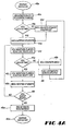
- Fig. 4A sets forth a flow chart showing the overall operation after the system 10 has been initialized.
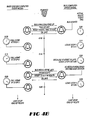
- Fig. 4B shows an example of a schedule of possible events and the interactions which might occur between the VCU 12 and the BSCU 14 as the bus 19 travels along its scheduled route and makes its scheduled stops.
- the left hand column illustrates the sequence of events for the BSCU 14, and the right hand column illustrates the sequence of events on the VCU 12. Between the right and left hand columns is illustrated a time line for the scheduled bus stops.
- the time line has the following time designations: ten minutes, sixteen minutes, and twenty-two minutes, all along the scheduled bus route.
- the bus ignition is switched on, as indicated in Fig. 4A at block 45a.
- the system 10 could be configured to automatically initialize itself upon power up of the VCU 12, and further, the unit 12 could be programmed to make initial contact with the BSCU 14 after the bus 19 moves a predefined distance, such as 1/8 mile, as determined by the odometer sensor 25a.
- This initialization action causes the microprocessor controller 16 to telephone the BSCU 12 to inform the BSCU 12 that the bus 19 is beginning its route and to initialize the BSCU 14 relative to the VCU 12.
- the foregoing action is indicated at flow chart block 45b (Fig. 4A).
- the bus driver can press the start/reset switch 21 on the VCU 12 to initialize the VCU 12.
- the display module 33 After initialization of the VCU 12, the display module 33 preferably displays "Stop Number 1" followed by the amount of time to reach stop number 1. The time continuously runs as the bus 19 progresses along the bus route.
- the VCU 12 determines, continuously or periodically, if the bus 19 is on time by analyzing the status of devices 21-25 (Fig. 1) in view of planned route data (derived from initialization). In the preferred embodiment, the VCU 12 at least compares its elapsed time from the clock 24 (Fig. 1) with its scheduled time from the planned route data. When the bus 19 is on time, the VCU 12 does not contact the BSCU 14, and the BSCU 14 commences calling students at the predefined time prior to arrival of the bus 19 at the particular bus stop, as indicated in flow chart block 45e (Fig. 4A). In the example of Fig. 4B, at five minutes along the scheduled route, the BSCU 14 places a telephone call to the homes 36 of the school children to be picked up at bus stop number 1.
- the VCU 12 determines that the bus 19 is early or late at this juncture, the VCU 12 contacts the BSCU 14, as indicated at flow chart block 45d (Fig. 4A), and the BSCU 14 adjusts its student calling lists accordingly so that the students are called in accordance with the predefmed time notice, e.g., five minutes.
- the VCU 12 again determines, continuously or periodically, if the bus 19 is on time by analyzing the devices 21-25 (Fig. 1). Preferably, in this regard, the VCU 12 at least compares its elapsed time with its scheduled time.
- the bus 19 arrives at the bus stop number 1 and takes one minute to load all the students at this stop onto the bus 19.
- the bus driver actuates the move forward switch 22.
- the display module 33 Upon actuating the move forward switch 22, the display module 33 preferably displays "Stop Number 2" followed by the amount of time to reach stop number 2.
- the foregoing feedback signal may be generated by one of the sensors 25a-25e so that the bus driver need not actuate the move forward switch 22.
- the microprocessor controller 16 checks the elapsed time of eleven minutes to confirm that such time corresponds to the programmed time for bus stop number 1. It will determine whether the bus 19 is early or late. If the bus 19 is either early or late, the VCU 12 will call the BSCU 14 to inform the unit 14 of this fact, as indicated at flow chart blocks 45g and 45h (Fig. 4A). If the bus 19 is on time, then the VCU 12 will continue to monitor the inputs from devices 21-25, as indicated in flow chart block 45j. In the example of Fig. 4B, it is assumed that the bus 19 is neither early nor late in leaving bus stop number 1.
- the bus 19 then arrives at bus stop number 2 and commences the boarding of students. However, because one of the school children is running late that particular morning, the bus 19 spends three minutes at bus stop number 2, and, thus, gets three minutes behind schedule. Thus, the bus departs at twenty minutes along the route.
- the VCU 12 makes an inquiry as to whether there are any more bus stops, as indicated in flow chart block 451. If so, then the VCU 12 again monitors its travel status by checking devices 21-25 (Fig. 1), in accordance with flow chart block 45f (Fig. 4A). If not, then the VCU 12 notifies the BSCU 14 of the end of the route, as indicated at flow chart block 45m.
- the microprocessor controller 16 upon receiving the information that the bus 19 is late, the microprocessor controller 16 compares the departure time to the scheduled departure time of seventeen minutes, pursuant to flow chart block 45f (Fig. 4A), and determines that the bus 19 is three minutes behind schedule, in accordance with flow chart blocks 45g (Fig. 4A). The microprocessor controller 16 then telephones the BSCU 14 to inform the BSCU 14 that the bus 19 is three minutes behind schedule, as indicated in flow chart block 45h (Fig. 4A). A fleet operator's screen associated with the BSCU 14 is updated to reflect the status of the late bus 19, as indicated at flow chart block 45i (Fig. 4A). Moreover, as indicated at flow chart block 45d (Fig.
- the BSCU 14 then reschedules the telephone calls that are to be made to the parents of the students at bus stop number 3 from twenty-two minutes along the route to twenty-five minutes along the route and resets the VCU 12 to seventeen minutes along the route, the scheduled time for the bus to leave bus stop number 2.
- the BSCU 14 calls the student homes 36 of the students corresponding to bus stop number 3, in accordance with flow chart block 45k (Fig. 4A), to inform them that the bus 19 is five minutes from arriving.
- the bus 19 arrives at bus stop 3, takes one minute to load the students on to the bus 19 and then proceeds onto the school.
- the VCU 12 makes an inquiry as to whether there are any more bus stops, as indicated in flow chart block 451.
- the VCU 12 notifies the BSCU 14 of the end of the route, as indicated at flow chart block 45m.
- system 10 may be configured so that if a bus 19 becomes delayed by more than a maximum length of time, such as fifteen minutes, the BSCU 14 immediately calls the homes 36 of the remaining students to board the bus 19 in order to notify these homes 36 of the unusual delay and to notify these homes 36 to wait for a notification call.
- a maximum length of time such as fifteen minutes
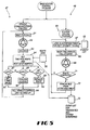
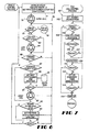
- Figs. 5 through 7 show flow charts pertaining to control programs that implement control processes or algorithms of the advance notification system 10 of Fig. 1 in order to achieve the functionality as set forth in Figs. 4A and 4B as described hereinbefore. These flow charts illustrate the best mode for practicing the invention at the time of filing this document. More specifically, Fig. 5 illustrates a base station control program 46 employed in the BSCU 14, and Figs. 6 and 7 show respectively a vehicle control program 76 and a VCU call control program 101 implemented in the VCU 12.
- the foregoing control programs implement merely examples of plausible control algorithms, and an infinite number of control algorithms may be employed to practice the present invention.
- the base station control program 46 essentially comprises two control subprograms which run concurrently, namely, (a) a vehicle communications program 47 and (b) a student calling program 48.
- the vehicle communications program 47 will be described immediately hereafter followed by the student calling program 48.
- the vehicle communications program 47 initially waits for a telephone call from one of the VCUs 12 located on one of the plurality of buses 19, as indicated by a flow chart block 51.
- the vehicle communications program 47 is preferably capable of monitoring a plurality of telephone connections 26' for receiving information from a plurality of buses 19. As the number of buses 19 is increased, the number of telephone connections 26' which are monitored by the vehicle communications program 47 should also be increased to an extent.
- the respective VCU 12 After the start of a bus 19 along its route, the respective VCU 12 will initiate a telephone call to the BSCU 14, as indicated by the telephone bell symbol 52. After the BSCU 14 receives the telephone call, a string of symbols is exchanged between the VCU 12 and the BSCU 14 so as to validate the communication connection, as indicated in a flow chart block 53. In other words, the BSCU 14 ensures that it is in fact communicating with the VCU 12, and vice versa.
- the BSCU 14 asks the VCU 12 for information regarding (a) the time into the route and (b) the number designating the next stop.
- route data 56 is obtained from a local data base.
- the route data 56 includes information pertaining to each bus stop and how much time it should take to reach each bus stop during the route. From the route data 56 and the information (a) and (b), as indicated previously, received from the VCU 12, the BSCU 14 can determine whether the bus 19 is late or early, as indicated by flow chart blocks 57, 58, or whether the bus 19 has just started its route, as indicated by a flow chart block 59.
- the BSCU 14 advises the VCU 12 to reset its on-board clock 24 back so that it thinks it is on time, as indicated in a flow chart block 61.
- the BSCU 14 advises the VCU 12 to move its on-board clock 24 forward so that the VCU 12 thinks it is on time, as indicated in flow chart block 62.
- the base station clock 28 and the on-board vehicle clock 24 are synchronized, as indicated in a flow chart block 63.
- the BSCU 14 informs the VCU 12 to terminate the telephone call, which was initiated in the flow chart block 51.
- the vehicle communications program 47 then proceeds once again to the flow chart block 51, where it will remain until receiving another telephone call from the bus 19.
- the BSCU 14 is the ultimate controller of the advance notification system 10 from a hierarchical vantage point.
- the base station clock 28 maintains the absolute time of the advance notification system 10, while the vehicle clock 24 assumes a subservient role and is periodically reset when the bus 19 is at the start of a route or when the bus 19 is either early or late during the route.
- the VCU 12 communicates to the BSCU 14 only (a) when the bus 19 is at the start of a route, (b) when the bus 19 is either early or late during the route, and (c) when the bus 19 completes its route, so as to minimize the amount of time on the mobile telephone network and associated costs thereof.
- the student calling program 48 runs concurrently with the vehicle communications program 47 within the BSCU 14. In essence, the student calling program 48 uses the timing information retrieved from the bus 19 by the vehicle communications program 47 in order to call students and inform them of the approaching bus 19.
- a student list 66 is locally accessible from a local data base by the BSCU 14 and comprises information regarding (a) student names, (b) student telephone numbers, and (c) the time into a bus route when a student should be called via telephone.
- the student list 66 is consulted as time progresses and telephone numbers are retrieved.
- the student calling program 48 initiates a telephone call to the particular student, as shown in flow chart blocks 68, 69.
- the telephone call can be made by using a distinctive telephone ring or a predefined number of rings, as described previously.
- the particular time is fully selectable by programming.
- the program can also include a feature for monitoring calls to be placed in the future. In accordance with this feature, upon anticipation of a heavy load of calls, some of the calls would be initiated earlier than the originally scheduled, corresponding call time.
- the particular bus and bus route are removed from consideration, as indicated by flow chart blocks 71, 72. Otherwise, the student calling program 48 returns to the student list 66 and searches for the next student to be called.
- an event list 73 is maintained for diagnostics and system monitoring.
- the event list 73 receives data from both the vehicle communications program 47 and the student calling program 46.
- the event list 73 essentially comprises records of, among other things, all telephone calls and all past and current bus locations.
- the VCU 12 runs through an initiation procedure in which the first stop number is retrieved, the stop time (time necessary to travel to the next stop) is retrieved, and the time into the route as indicated by the clock 24 is set at zero and the clock 24 is started.
- a call is initiated via the transceiver 18 to the BSCU 14, as indicated by the bell symbol 78.
- the VCU 12 and the BSCU 14 exchange information as described hereinbefore and which will be further described hereinafter relative to Fig. 7.
- the vehicle control program 76 begins a looping operation wherein the VCU 12 continuously monitors the switches 21-23, clock 24, and sensors 25a-25e, if present, to determine whether the bus 19 is early or late. As mentioned previously, the vehicle control program 76 initiates a call only at start-up of a route, or when the bus 19 is either early or late, and not when the bus 19 is on time.
- the program 76 determines whether any of the switches 21, 22, 23 have been actuated, as indicated in a decisional flow chart block 86. If none of the switches 21, 22, 23 have been actuated, then the program 76 will loop back around and begin flow chart block 81 once again. Otherwise, if actuation of a switch 21, 22, 23 is detected, then the program 76 will determine which of the switches 21, 22, 23 has been actuated.
- the program 76 will determine whether the move forward switch 22 has been actuated, as indicated in the decision flow chart block 87. If the bus driver has actuated the move forward switch 22, then the VCU 12 will retrieve the next stop number and corresponding stop time, as indicated in flow chart block 88, from a local data base having the route data 56. Moreover, a decision will be made as to whether the bus 19 is early for that particular stop, as indicated in the decision flow chart block 91. In the preferred embodiment, the bus 19 is considered early if the bus 19 arrives at a stop more than a predetermined early time period, such as 50 seconds, earlier than when it should have arrived. If the bus is not early, then the program 76 will loop back and proceed again with the flow chart block 81. Otherwise, a call will be initiated to the BSCU 14 to inform the unit 14 that the bus 19 is early, as illustrated by bell symbol 92 in Fig. 7.
- the program 76 proceeds to a decisional flow chart block 93 wherein the program 76 determines whether the move backward switch 23 has been actuated by the bus driver. If the move backward switch 23 has been actuated, then the program 76 obtains the previous stop number and stop time, as indicated in flow chart block 94, displays these values on the display screen, and loops back to begin again with the flow chart block 81.
- the program 76 determines whether the bus driver has actuated the start/reset switch 21, as indicated in the decisional flow chart block 96. If the start/reset switch 23 has not been actuated by the bus driver, then the program 76 loops back and begins again with the flow chart block 81. Otherwise, the program 76 loops back and begins again with the flow chart block 77.
- the VCU 12 When a call is initiated by the VCU 12 as indicated by the call symbols 78, 84, 92, the VCU 12 follows the VCU call control program 101 as illustrated in Fig. 7. Initially, if a mobile telephone is used by the VCU 12, the telephone number corresponding with the BSCU 14 is obtained from the EEPROM 43, as indicated in a flow chart block 102. Other information is also obtained, including among other things, the particular bus number, bus serial number, and bus route. Next, the VCU call control program 101 sets a time out variable to keep track of how many times a communication connection has been initiated. The number n of allowable attempts is predetermined and is stored in the EEPROM 43.
- the VCU call control program 101 causes the transceiver 18 to be called, as indicated in the flow chart block 104.
- the call control program 101 requires the VCU 12 to wait for a response from the BSCU 14. If the VCU 12 does not receive a response within a predetermined time out period, preferably 20 seconds, then the VCU call control program 101 loops back and begins again at the flow chart block 103. Otherwise, when the VCU call control program 101 determines that a response has been received, a validation procedure ensues, as indicated in a flow chart block 108.
- the validation process indicated at the flow chart block 108 is that which was described previously relative to the flow chart block 53 of Fig. 5. Essentially, it involves the exchange of symbols in order to assure a proper connection.
- Another time out variable is set and will trigger termination of the telephone connection after a predetermined time period has run.
- the initiation of the time out variable and monitoring of the same is indicated in Fig. 7 at flow chart block 111. If the time out variable triggers termination of the telephone connection, then the VCU call control program 101 will hang up and end the call, as illustrated by a flow chart block 114. Otherwise, when the validation procedure has fully commenced, commands are passed from the BSCU 14 to the VCU 12, as shown by a flow chart block 112. Commands which may be sent to the VCU 12 include, for example, the following: (1) Is the bus 19 either early or late?; (2) Reset the vehicle clock 24; (3) Record new information in the EEPROM 43. It should be emphasized that the BSCU 14 may change the route information contained within the EEPROM 43 of the particular bus 19. The foregoing features enables extreme flexibility of the advance notification system 10.
- the VCU call control program 101 determines whether the BSCU 14 has finished its communication over the mobile telephone, as indicated in a flow chart block 113. Again, the VCU call control program 101 utilizes another time out variable to determine whether the BSCU 14 has finished. After the predetermined time period of the time out variable, the VCU call control program 101 will assume that the BSCU 14 has terminated its communication, and accordingly, the VCU call control program 101 will hang up the telephone, as indicated in a flow chart block 114. Otherwise, the VCU call control program 101 will loop back and begin with the flow chart block 111 in order to accept another command from the BSCU 14.
- a user of the system 10 can communicate with and manage the BSCU 14 of the system 10 through an interactive system, such as an interactive voice response system (IVR) or other suitable communication system.
- IVR interactive voice response system
- This interactive system provides the user with flexibility and control over the calling parameters and the ability to solicit information, i.e. , reports.
- the user may (a) enroll and/or make changes to the calling parameters of the BSCU 14, including defining the preset notification time period when the user is to receive a telephone call prior to arrival of the vehicle 29 at the stop (to thereby indicate impending arrival of the vehicle 29), (b) obtain a vehicle progress report so as to check on vehicle delays or if the user has missed the vehicle, and/or (c) receive a calling report on the last notification attempt.
- the BSCU 14 is configured so that when a user requests any of the foregoing information, the telephone number of the user telephone 29 is checked by the BSCU 14. If a user's telephone service has the commercially available feature typically known as "calling line identification," the BSCU 14 compares the caller's telephone number with a previously-registered number (reference caller identification number) stored in the student list database 66 (Fig. 5). If the incoming number does not match or if the telephone connection does not provide the calling line identification, then the user is prompted to enter his/her telephone number to the BSCU 14. Moreover, the telephone number received by the BSCU 14 must be the one registered in the BSCU 14 for the aforementioned options to be used.
- the BSCU 14 of the system 10 requests the user to enter its phone number, and the telephone number is registered.
- the BSCU 14 then calls the user back at the telephone number registered in the BSCU 14 to confirm, before the user can change calling parameters or solicit information from the BSCU 14.
- the BSCU 14 can recognize the directory number. In that case, the BSCU 14 will not have to call the user back to register, and enrollment can continue.
- IVR interactive voice response system
- the service provided by the system 10 can be started when the system user calls into the interactive voice response system (IVR) from a telephone 29, preferably a touch-tone telephone.
- IVR interactive voice response system
- the system user receives a prompt to enter his/her telephone number.
- the user hangs up, and the BSCU 14 calls the system user back, unless calling line identification is in use as described previously.
- Changes are only allowed if the telephone number derived from the calling line identification matches the BSCU registered number or if the entered telephone number matches the registered number.
- the BSCU 14 provides voice prompts to guide the user through a telephone call when the user wishes to configure the BSCU 14 or retrieve information.
- voice prompts ask for the (a) bus number and the (b) stop number. These two pieces of information are usually given by the bus driver the first time the student rides the bus 29.
- the information can be taken from the VCU display module 33 (Fig. 3A) of the VCU 12 and/or written on a marketing brochure in which the student takes home.
- the preset notification time period mechanism 9 (Fig. 3B) permits the user to define a preset notification time period when the user is to receive a telephone call prior to arrival of a vehicle 19 at a vehicle stop to thereby indicate impending arrival of the vehicle 19 at the stop.
- the preset notification time period can be provided by the user to BSCU 14 by depressing touch tone buttons on the user telephone 29 or other telephone.
- the default for the notification time period is set to any suitable period, such as five minutes. Moreover, the user prescribed time period or the default time period is announced to the user. Finally, if a change of the preset notification time period is needed, the user is prompted through the process.
- the vehicle progress report generator 13 (Fig. 3B) in the BSCU 14 allows a system user to solicit information from the BSCU 14 pertaining to the progress of the vehicle 29 relative to its route and/or relative to a particular stop. A system user may feel that the vehicle 29 was missed. By calling the BSCU 14 and pressing the appropriate option, the IVR provides information about the current vehicle location.
- the calling report generator 11 (Fig. 3B) in the BSCU 14 allows a system user to solicit a calling report from the BSCU 14.
- the calling report can indicate, among other things, the time(s) and outcome(s) of any previous notification attempt(s) by the BSCU 14 to the user telephone 29.
- the BSCU 14 can be programmed to make any number of attempts, but preferably, the BSCU 14 makes three attempts to provide notification.
- This calling report generator 11 can also be configured to allow the system user to check on the last changes made to the calling parameters. In this configuration, the IVR gives the change made and the date the change was requested by the system user.
- the present invention also relates to a method for an advance notification system, the method for allowing a system user to define a preset notification time period when the user is to receive a telephone call prior to arrival of a vehicle at a vehicle stop to thereby indicate impending arrival,
- the advance notification system comprising (a) a user telephone associated with said user, (b) system control for monitoring travel of said vehicle in relation to the vehicle stop, and (c) a system telephone interface for establishing a telephone connection between said system control and said user telephone when said vehicle is at a location that corresponds with the preset notification time period from said vehicle stop, the method comprising the steps of: (a) permitting said user to define said preset notification time period by the following steps: (1) establishing a telephone communication link with said system telephone interface; and (2) providing said preset notification time period to said system control during said telephone communication link.
- This method may further comprise the steps of: maintaining a reference caller identification number associated with said user telephone; and when said telephone communication link is established, determining whether said telephone communication link is authorized by comparing a caller identification number associated with said telephone communication link with said reference caller identification.
- This method may further comprise the step of providing said preset notification time period to said system control by depressing touch tone buttons on said user telephone.
- the present invention also relates to an advance notification system that allows a user to define a preset notification time period when the user is to receive a telephone call prior to arrival of a vehicle at a vehicle stop, the call for indicating impending arrival of the vehicle at the vehicle stop, comprising: a user telephone associated with said user; a system control for monitoring travel of said vehicle in relation to the vehicle stop; a system telephone interface in communication with said system control, said system telephone interface for establishing a telephone connection with said user telephone when said vehicle is at a location that corresponds with the preset notification time period from said vehicle stop; and user configuration means associated with said system control, said user configuration means for permitting said user to define said preset notification time period by providing said preset notification time period to said system telephone interface over a telephone communication link established between said user and said system telephone interface.
- This system may further comprise: means for storing a reference caller identification number associated with said user telephone; and means for, when said telephone communication link is established, determining whether said telephone communication link is authorized by comparing a caller identification number associated with said telephone communication link with said reference caller identification.
- This system may be adapted to monitor a distance travelled by said vehicle.
- This system may also be adapted to monitor time travelled by said vehicle.
Abstract
Description
- The present invention generally relates to data communications and information systems and, more particularly, to an advance notification system and method for notifying system users in advance of the impending arrival of a transportation vehicle, for example but not limited to, a bus, train, plane, fishing vessel, or other vessel, at a particular vehicle stop.
- There are many situations when it is desirable for persons to know of the approximate arrival time of a particular transportation vehicle shortly before the vehicle is to arrive at a particular destination. With such information, passengers or other or users of the inventive system and method can adjust their schedules accordingly and avoid having to wait on the particular vehicle to reach the particular destination. For example, a person having to pick up a friend or relative at a commercial bus station either has to call the bus station to find out the approximate arrival time, which information is oftentimes unavailable, or plan on arriving at the bus station prior to the scheduled arrival time of the bus and hope the bus is not delayed. Thus, a system user may include, but is not limited to, a passenger or any person affected by a transportation vehicle.
- Another example is in the commercial fishing industry, wherein fish markets, restaurants, and other establishments desire to purchase fish immediately upon arrival of a commercial fishing boat at a port. Currently, such establishments, in order to ensure being able to purchase the freshest catch, often depend on predetermined schedules of fishing fleets, which are not always accurate or reliable.
- Still another example involves school children who ride school buses. School children who ride buses to school often have to wait at their bus stops for extended lengths of time because school buses arrive at a particular bus stop at substantially different times from one day to the next. The reason is that school buses are not always the best maintained vehicles on the roads, frequently must operate during rush hour traffic, and must contend with congested urban/suburban conditions. As a result, school children are forced to wait at their bus stops for long periods of time, oftentimes in adverse weather conditions, on unlit street comers, or in hazardous conditions near busy or secluded streets. If it is raining, snowing, windy and cold, or even dark, such conditions can be unhealthy and unsafe for children.
- Thus, generally, it would be desirable for a person to know when a vessel, such as a bus, train, plane, or the like, is a particular time period (number of minutes or seconds) from arriving at a destination so that the passenger or other persons affected by the transportation system can adjust his/her schedule and avoid arriving too early or late.
- In the past, in order to combat the arrival time problem in the context of school buses, student notification systems have been employed that use a transmitter on each bus and a receiver inside each student home. U.S. Patent No. 4,713,661 to Boone et al. and U.S. Patent No. 4,350,969 describe systems of this type. When the school bus and its on-board transmitter come within range of a particular home receiver, the transmitter sends a signal to the receiver, which in turn produces an indicator signal to notify the student that his/her school bus is nearby. While such notification systems work satisfactorily under certain circumstances, nevertheless, these systems are limited by the range of the transmitters and require the purchase of relatively expensive receivers for each student. In addition, such systems provide little flexibility for providing additional information to the students, such as notifying them of the delayed arrival of a bus, alternative bus route information, or information regarding important school events.
- US-A-5,400,020 discloses an advance notification system and method for notifying school children of the impending arrival of their school bus. The system includes an on-board vehicle control unit for each bus and a base station control unit for making telephone calls to the homes of school children in order to inform them that the bus is a certain time period away from a bus stop. The vehicle control unit compares elapsed time to the programmed scheduled time for each bus stop to determine if the bus is on schedule. If the bus is behind or ahead of schedule, the vehicle control unit calls the base station control unit, which then resets its calling schedule accordingly.
- An object of the present invention is to overcome the deficiencies and inadequacies of the prior art as noted above and as generally known in the industry.
- Another object of the present invention is to provide an advance notification system and method for according advance notification of the impending arrival of a vehicle at a particular vehicle stop.
- Another object of the present invention is to provide an advance notification system and method for according advance notification to school students of the impending arrival of a school bus at a particular bus stop.
- Another object of the present invention is to provide an advance notification system and method for inexpensively according advance notification of the impending arrival of a vehicle at a particular vehicle stop.
- Another object of the present invention is to provide an advance notification system that is reliable in operation and flexible in design to permit customization to a particular application.
- Briefly described, the present invention is an advance notification system for notifying persons of an impending arrival of a vehicle as the vehicle progresses along a scheduled route with particular stop locations and corresponding scheduled times of arrival at the stop locations. The advance notification system generally comprises a vehicle control unit (VCU) disposed on each vehicle and a base station control unit (BSCU) which is configured to communicate with all of the vehicle control units and with telephones used by passengers or persons affected by or depending on the arrival or departure of the transportation vehicle.
- The VCU includes a vehicle control mechanism, a vehicle communication mechanism controlled by the vehicle control mechanism, a vehicle clock for tracking elapsed time of the vehicle while on the scheduled route to determine when the vehicle is early, late, and on time along the scheduled route, optional input switches (e.g., start/reset, advance stop number, move stop number back) that can be operated by the vehicle driver to indicate when the vehicle has reached particular stops along the route, and optional sensors (e.g., odometer, door sensor, swing arm sensor, bus stop sensor, positioning system input, etc. ) for signalling to the vehicle control mechanism when the vehicle is early, late, and on time along the scheduled route. The control mechanism is adapted to initiate calls utilizing the vehicle communication mechanism when the elapsed time and/or travelled distance of the vehicle at any of the particular positions is either ahead or behind the scheduled time and/or distance. In the preferred embodiment, the vehicle communication mechanism is a wireless communication interface, such as a mobile telephone, radio frequency (RF) transceiver, or other suitable device.
- The BSCU has a base station communication mechanism and a base station control mechanism for controlling the base station communication mechanism. The base station communication mechanism receives the calls from the VCU and receives the amount of time and/or distance in which the vehicle is ahead or behind relative to the schedule. The base station control mechanism causes calls to be made to each of the passengers to be boarded at a particular stop location via the base station communication mechanism prior to the arrival of the vehicle at the particular stop location. In the preferred embodiment, the base station communication mechanism is a wireless communication device, such as a mobile telephone or RF transceiver (includes both transmitter and receiver), for communicating with the vehicle communication mechanism and also comprises at least one telephone for calling passenger telephones or telephones associated with persons affected by the transportation vehicle.
- The telephone call to advise a person of the impending arrival of the vehicle preferably can exhibit a distinctive telephone ring sound so that the call recipient need not answer the telephone in order to receive the message. Moreover, the distinctive telephone ring sound can be coded by any sequence and duration of rings and/or silent periods.
- In accordance with a significant feature of the present invention, a calling report generator in the BSCU allows a person to solicit a calling report from the BSCU. The report can indicate the time(s) and outcome(s) of any previous notification attempt(s) by the BSCU to the telephone possessed by a passenger or person affected by the transportation vehicle.
- It should be emphasized that while the present invention is particularly suited for application to school buses, there are many other applications. As examples, the advance notification system and method of the present invention could be employed with commercial buses, trains, planes, pickup vehicles, delivery vehicles, fishing vessels, and numerous other transportation vehicles.
- Other objects, features, and advantages of the present invention will become apparent from the following specification, when read in conjunction with the accompanying drawings. All such additional objects, features, and advantages are intended to be included herein.
- The present invention can be better understood with reference to the following drawings. The drawings are not necessarily to scale, emphasis instead being placed upon clearly illustrating principles of the present invention.
- Fig. 1 is a high level schematic diagram of an advance notification system of the present invention as applied to a school bus system, as an example, the advance notification system generally comprising vehicle control units (VCU) in communication with a base station control unit (BSCU), which are in turn in communication with passenger telephones;
- Fig. 2 is a high level block diagram of the VCU of the advance notification system of Fig. 1;
- Fig. 3A is a low level block diagram of the VCU of Fig. 1;
- Fig. 3B is a block diagram of the BSCU of Fig. 1;
- Fig. 4A is a flow chart of the overall operation of the advance notification system of Fig. 1;
- Fig. 4B is an example of a schedule for a sequence of events illustrating the operation of the advance notification system of Fig. 1;
- Fig. 5 is a flow chart of a base station control program for the base
station control unit 14 of Fig. 1 that includes a vehicle communications program and a student calling program; - Fig. 6 is a flow chart of a vehicle control program for the VCU of Figs. 1 and 2; and
- Fig. 7 is a flow chart of a VCU call control program for the VCU of Figs. 1 and 2.
-
- The features and principles of the present invention will now be described relative to a preferred embodiment thereof. It will be apparent to those skilled in the art that numerous variations or modifications may be made to the preferred embodiment without departing from the spirit and scope of the present invention.
- Referring now in more detail to the drawings, wherein like reference numerals designate corresponding parts throughout the several views, Fig. 1 is a schematic diagram of the
advance notification system 10 of the present invention as configured to operate in, for example but not limited to, a school bus system. Theadvance notification system 10 comprises, preferably, a plurality of on-board vehicle control units (VCU) 12, a single base station control unit (BSCU) 14, and a plurality oftelephones 29. As configured in theschool bus system 10, aVCU 12 is installed in each of a plurality ofschool buses 19, all of which communicate with thesingle BSCU 14. Moreover, theBSCU 14 communicates with atelephone 29 at one ormore locations 36, or student homes in the present exemplary application. - The
VCU 12 will now be described with reference to Figs. 1, 2, and 3. Referring first to Fig. 1, eachVCU 12 comprises amicroprocessor controller 16, preferably a model MC68HC705C8P microprocessor controller that is manufactured by and commercially available from the Motorola Corporation, U.S.A. Themicroprocessor controller 16 is electrically interfaced with acommunication mechanism 18, preferably a wireless communication device, for enabling intercommunication of data with theBSCU unit 14. Examples of suitable wireless communication devices include a mobile telephone (e.g., cellular) and a transceiver (having both a transmitter and receiver) operating at a suitable electromagnetic frequency range, perhaps the radio frequency (RF) range. - In the embodiment using a wireless RF transceiver as the
communication mechanism 18, data can be sent in bursts in the form of in-band tones, commonly called "twinkle tones." These tone bursts can occur in the background of an existing voice channel. Twinkle tones are oftentimes used in transportation systems, such as taxi cab communications systems. - The
microprocessor controller 16 is electrically interfaced with a start/reset switch 21, a move forward switch 22, a move backward switch 23, aclock 24, and optionally,sensors 25a-25d. Generally, vehicle tracking is accomplished by monitoring the control switches 21-23, thesensors 25a-25e, the power to thecontroller 16, and a route database (Fig. 5). It is recommended that all of the foregoing features be employed to provide redundant checking. - More specifically, the start/
reset switch 21 can be actuated by the bus driver upon starting along the bus's scheduled route to initialize thesystem 10. The move forward switch 22 can be actuated by the bus driver upon reaching a bus stop in order to inform theVCU 12 that a stop has been made, the details of which will be further described hereinafter. The move backward switch 23 can be actuated by the bus driver at a bus stop if the bus driver has erroneously toggled the move forward switch 22 too many times, as will be further described in detail hereinafter. This indicates to themicroprocessor controller 16 that adisplay module 33 and memory must be updated. In essence, the move forward switch 22 and the move backward switch 23 cause the next stop designation which is displayed on thedisplay module 33 and stored in theVCU 12 to toggle forward and backward, respectively. - The
VCU 12 can be configured so that the operation of the start/reset switch 21, the move forward switch 22, and the move backward switch 23 is purely optional by the bus driver. In this configuration, thesensors 25a-25e automatically accomplish the aforementioned functions of the switches 21-23. However, in certain cases, the bus driver may want to use the switches to override thesensors 25a-25e. One of these cases may be when a student rides a bus only two out of five school days. Rather than program theVCU 12 to track these unnecessary stops, the driver may manually control the stop number by the switches 21-23. - The
clock 24 tracks the elapsed time as the bus travels along its scheduled route and feeds the timing information to themicroprocessor controller 16. - The
display module 33 informs the bus driver as to the number corresponding to the next stop and the time (preferably, in seconds) necessary to reach the next stop. Other types of information may also be displayed on thedisplay module 33. For example, thedisplay module 33 may display the amount of time that thebus 19 is ahead of or behind schedule, the status of theVCU 12 in communication with theBSCU 14, or, upon actuation ofstart button 21, that theadvance notification system 10 is operating. - The
optional sensors 25a-25e include anodometer sensor 25a for determining distance into a route. Thissensor 25a can be connected to the bus drive shaft and counts revolutions. This data can be used to determine the stop number. - A
door sensor 25b can be used to count the number of door operations (opening/closing) of the front door of theschool bus 19, which should correspond with the number of stops. - A swing arm sensor 25c can be implemented to count the number of times the arm operates. This operation should coincide with the number of stops.
- A bus
stop sign sensor 25d can be utilized to count the number of times the bus stop sign operates. This operation should coincide with the number of stops. - A
positioning system 25e can be used to determine the geographical position of thebus 19 on the earth's surface. Thepositioning system 25e could be the GPS (global positioning system), the LORAN positioning system, the GLONASS positioning system (USSR version of GPS), or some other similar position tracking system. - Fig. 2 is a high level schematic circuit diagram of the
VCU 12. TheVCU 12 is designed to be a compact unit with a generallyrectangular housing 34 that is mounted preferably on or in front of the dashboard of thebus 19 in view and within reach of the bus driver. In thehousing 34, themicroprocessor controller 16 is interfaced with thetransceiver 18 by a transceiver jack 31 (preferably a conventional 8-conductor telephone jack whentransceiver 18 is a mobile telephone), and thetransceiver 18 includes anantenna 32 for transmitting and receiving signals to and from theBSCU 14. Further, theVCU 12 includes a liquid crystal display (LCD)module 33 disposed for external viewing of the display by the bus driver for providing information to the bus driver, as described previously. - Fig. 3A is a more detailed schematic circuit diagram of the electronic components associated with the
VCU 12. Themicroprocessor controller 16 essentially controls the operation of thetransceiver 18 and theLCD display module 33. A switchingelement 37, such as an optical isolator (opto isolator)unit 37, provides a buffer between themicroprocessor controller 16 and thebattery 35 as well as switches 21, 22, 23. AnEEPROM 43 is provided for storing the control programs (Figs. 6 and 7) and other requisite data for themicroprocessor controller 16, and aRAM 44 is provided for running the control programs in themicroprocessor controller 16. Amatrix keyboard emulator 39 is interfaced between thetransceiver 18 and themicroprocessor controller 16 for allowing the microprocessor controller to control and transmit signals over thetransceiver 18. Further, a dual tonemultiple frequency decoder 41 is interfaced between themobile telephone 18 and themicroprocessor controller 16 for decoding modem signals, or tones, received by themobile telephone 18 from theBSCU 14. - The
BSCU 14 can be implemented by any conventional computer with suitable processing capabilities for implementing the functionality described hereafter. TheBSCU 14 is now described with reference to Figs. 1 and 3B. - In general, as shown in Fig. 1, the
BSCU 14 includes at least one transceiver 26 (for example, a mobile telephone or RF transceiver) and associated communication connection 26' dedicated for communication with the one ormore VCU transceivers 18 associated with the respective one ormore VCUs 12. Moreover, theBSCU 14 can communicate to one ormore telephones 29, or student homes, via the telephone interface(s) 27 and telephone connection(s) 29'. - As illustrated in Fig. 3B, the
BSCU 14 contains aconventional processor 2. Theprocessor 2 intercommunicates with and controls the other elements within theBSCU 14 over asystem bus 3. An input device(s) 4, for example, a keyboard or mouse, is used to input data from a user (perhaps a fleet operator) of theBSCU 14, and an output device(s) 5, such as a display or printer, is used to output data to the user. Anonvolatile storage device 6, for example, a hard disk drive or CDROM mechanism, may be used to permanently store the software of theBSCU 14, as well as to store the data bases generated by theBSCU 14. - A high speed volatile memory 7, such as a conventional random access memory (RAM), contains the software for driving the
processor 2 during operation of theBSCU 14. Particularly, the RAM 7 is loaded with a conventional operating system software (e.g., DOS, UNIX, etc. ) for supporting and implementing other software programs for implementing various novel features of theBSCU 14. These other software programs preferably include a preset notificationtime period mechanism 9, a callingreport generator 11, a vehicleprogress report generator 13, and a base station control program 46 (Fig. 5) that has avehicle communications program 47, and astudent calling program 48. The foregoing software programs are loaded as needed into the RAM 7, as needed, by theprocessor 2. - The preset notification
time period mechanism 9 permits a system user to define a preset notification time period when he or she is to receive a telephone call prior to arrival of avehicle 19 at a vehicle stop to thereby indicate impending arrival of thevehicle 19 at the stop. The preset notificationtime period mechanism 9 can be implemented in software in many different manners, as is well known to someone with skill in the art. Preferably, the preset notificationtime period mechanism 9 allows a system user or passenger to define the period by (a) establishing a telephone communication link with thesystem telephone interface 27 and (b) providing the preset notification time period to themechanism 9 during the telephone communication link. - The calling
report generator 11 can be implemented in a variety of ways in software and is preferably configured to permit the system user to solicit a calling report corresponding to one or more previous telephone calls made by thesystem telephone interface 27 to thesystem user telephone 29. In order to obtain the calling report, the user (a) establishes a telephone communication link with thesystem telephone interface 27 and (b) requests the report. In turn, the callingreport generator 11 provides the calling report to the user in real time during the telephone communication link. The calling report can be configured to indicate whether theuser telephone 29 was busy, was answered, was not answered, or was out of service, when thesystem telephone interface 27 initiated the previous telephone call(s) to theuser telephone 29. Further, the calling report can be designed to include a time(s) when the previous telephone call(s) was (were) initiated by thesystem telephone interface 27 to theuser telephone 29. - The vehicle
progress report generator 13 may be implemented in many different ways in software and is configured to permit the user to solicit a vehicle progress report relating to arrival of thevehicle 19 at the vehicle stop. Preferably, a user can solicit a vehicle progress report from the vehicleprogress report generator 13 by (a) establishing a telephone communication link with thesystem telephone interface 27 and (b) requesting the report. In turn, the vehicleprogress report generator 13 provides the report to the user in real time during the telephone link. When thevehicle 19 is currently approaching the stop, a time indicating when thevehicle 19 is to arrive at the stop can be specified in the vehicle progress report. When thevehicle 19 has already arrived at the stop, a past arrival time can be specified in the progress report. Furthermore, the progress report may include a time(s) when a previous call(s) was initiated by thesystem telephone interface 27 to theuser telephone 29. - As shown in Fig. 3B, the
BSCU 14 further includes at least one transceiver 26 (for example, a mobile telephone or RF transceiver) and associated communication connection 26' dedicated for communication with the one ormore VCU transceivers 18 associated with the respective one ormore VCUs 12. The vehicle communications program 47 (Fig. 5) drives theprocessor 2 to control thetransceiver 26 and communications associated therewith. - The
BSCU 14 can communicate to one ormore user telephones 29, or student homes, via the telephone interface(s) 27 and telephone connection(s) 29'. Thetelephone interface 27 can be, for example but not limited to, any of the following interfaces: (a) a voice card(s) (preferably multiple port) and/or telephone; (b) a high-speed switch-computer applications interface(s) (SCAI) that communicates to a digital switch operated by a telephone utility company; the SCAI adheres to the conventional OSI model and supports the carrying of application information in an application independent fashion; and (c) an interface that communicates with an analog display services interface(s) (ADSI) maintained by a telephone utility company. ADSI is a cost effective technology that delivers voice and data information between a telephone terminal and a digital switch or server using existing copper telephone lines. - The
BSCU 14 could be configured to merely call users, thus warning them of the impending arrival of abus 19, as opposed to forwarding both a call and a message. Specifically, the student calling program 48 (Fig. 5) for theadvance notification system 10 can be designed to make the telephone calls to thehomes 36 of the students and allow the telephone to ring a predefined number of times so that it is not necessary for the telephone to be answered in order for the telephone call to be recognized as that of theadvance notification system 10. - The student calling program 48 (Fig. 5) associated with the
advance notification system 10 can also be configured to make theuser telephone 29 exhibit a distinctive telephone ring sound, or pattern, so that the call recipient need not answer the telephone in order to receive the message. The distinctive telephone ring can be coded by any sequence and duration of rings and/or silent periods. A standard ring signal that is sent to a telephone from the telephone utility company is typically a periodic electrical analog signal having a frequency of 20 Hz and a peak-to-peak voltage amplitude of -48 volts. The ring signal is asserted on the telephone connection 29' for a predefined time period for ringing the telephone. The foregoing time period can be manipulated in order to derive a distinctive sequence and duration of rings and/or silent periods. - Implementation of a distinctive telephone ring can be accomplished by purchasing this feature from a telephone utility company. This feature is widely available to the public. Generally, telephone utility companies operate network switches, now usually digital, that serve as interfaces for telephonic communications. A particular geographic region is typically allocated to a particular switch(s). In essence, one or more distinctive telephone rings can be driven by software running in the switches to a particular telephone. Examples of switches that are commercially available to telephone utility companies are as follows: a model DMS100 by Northern Telecom, Canada; a model 5ESS by AT&T, U.S.A.; and a model EWSD by Siemans Stromberg-Carlson Corp., Germany.
- The feature for establishing the distinctive telephone ring is sold to the public under several different commercial trade names, depending upon the telephone utility company. Examples are as follows: Call Selector by Northern Telecom, Canada; Ringmaster by Bell South, U.S.A.; Smartlink by SNET, U.S.A.; Multi-ring by Ameritech, U.S.A.; Priority Ring by PacBell, U.S.A.; Priority Call by Cincinnati Bell, U.S.A.; and Ring Me by Standard Telephone Co., U.S.A.
- Furthermore, in the case where a parent or a student answers the telephone call from the
base station unit 14, a prerecorded message may be played by theBSCU 14. An example of such a message would be: "The bus will arrive in five minutes," as indicated in Fig. 1 at thereference numeral 30. - Initially, the bus schedule for each
bus 19 is programmed into theadvance notification system 10 by having the respective bus driver drive his respective bus one time along the corresponding scheduled bus route at the approximate speed the bus would usually travel on the route and with the bus driver making all the scheduled stops along the route and waiting at each stop for the approximate time it would take for all the students at that stop to board thebus 19. As the bus driver drives thebus 19 along the route for initialization purposes, the internalreal time clock 24 runs and the bus driver actuates theswitches RAM 44 and EEPROM 43) of theVCU 12. - The timing information which is recorded during the initialization of the
system 10 is used as a reference during the usual operation of thesystem 10 for the purpose of determining whether abus 19 is early or late at each of the bus stops. In the preferred embodiment, determining the status (i.e., early, on time, late) of abus 19 is accomplished by comparing the time at which abus 19 actually departs from a stop to the scheduled time of departure. - However, it should be emphasized that other methodologies could be utilized for determining whether the
bus 19 is early or late at an instance in time. For example, theodometer 25a of thebus 19, as indicated by phantom lines in Fig. 1, could be monitored by themicroprocessor controller 16. At particular times, the odometer mileage reading could be compared to reference odometer mileage readings which were obtained during the initialization of thesystem 10. In this way, the determination of whether abus 19 is early or late can occur at any time during a bus route and can occur as many times as desired. - Another methodology which could be utilized for determining whether the
bus 19 is early or late involves interfacing theVCU 12 with thepositioning system 25e, as shown in Fig. 1 by phantom lines. From the geographical position data received from thepositioning system 25e, themicroprocessor controller 16 could determine where thebus 19 is situated on the earth at any given time. The bus location at a particular time could then be compared with scheduled locations and scheduled times in order to determine whether thebus 19 is early or late and by what amount. - The overall operation of the
advance notification system 10 will be described with reference to Figs. 4A and 4B. Fig. 4A sets forth a flow chart showing the overall operation after thesystem 10 has been initialized. Fig. 4B shows an example of a schedule of possible events and the interactions which might occur between theVCU 12 and theBSCU 14 as thebus 19 travels along its scheduled route and makes its scheduled stops. - In Fig. 4B, the left hand column illustrates the sequence of events for the
BSCU 14, and the right hand column illustrates the sequence of events on theVCU 12. Between the right and left hand columns is illustrated a time line for the scheduled bus stops. The time line has the following time designations: ten minutes, sixteen minutes, and twenty-two minutes, all along the scheduled bus route. - First, the bus ignition is switched on, as indicated in Fig. 4A at
block 45a. At the beginning of the bus route, thesystem 10 could be configured to automatically initialize itself upon power up of theVCU 12, and further, theunit 12 could be programmed to make initial contact with theBSCU 14 after thebus 19 moves a predefined distance, such as 1/8 mile, as determined by theodometer sensor 25a. This initialization action causes themicroprocessor controller 16 to telephone theBSCU 12 to inform theBSCU 12 that thebus 19 is beginning its route and to initialize the BSCU 14 relative to theVCU 12. The foregoing action is indicated atflow chart block 45b (Fig. 4A). Alternatively, the bus driver can press the start/reset switch 21 on theVCU 12 to initialize theVCU 12. - After initialization of the
VCU 12, thedisplay module 33 preferably displays "StopNumber 1" followed by the amount of time to reachstop number 1. The time continuously runs as thebus 19 progresses along the bus route. - Next, as indicated at
flow chart block 45c (Fig. 4A), theVCU 12 determines, continuously or periodically, if thebus 19 is on time by analyzing the status of devices 21-25 (Fig. 1) in view of planned route data (derived from initialization). In the preferred embodiment, theVCU 12 at least compares its elapsed time from the clock 24 (Fig. 1) with its scheduled time from the planned route data. When thebus 19 is on time, theVCU 12 does not contact theBSCU 14, and theBSCU 14 commences calling students at the predefined time prior to arrival of thebus 19 at the particular bus stop, as indicated inflow chart block 45e (Fig. 4A). In the example of Fig. 4B, at five minutes along the scheduled route, theBSCU 14 places a telephone call to thehomes 36 of the school children to be picked up atbus stop number 1. - However, when the
VCU 12 determines that thebus 19 is early or late at this juncture, theVCU 12 contacts theBSCU 14, as indicated atflow chart block 45d (Fig. 4A), and theBSCU 14 adjusts its student calling lists accordingly so that the students are called in accordance with the predefmed time notice, e.g., five minutes. - Further, as indicated at
flow chart block 45f (Fig. 4A), theVCU 12 again determines, continuously or periodically, if thebus 19 is on time by analyzing the devices 21-25 (Fig. 1). Preferably, in this regard, theVCU 12 at least compares its elapsed time with its scheduled time. - Back to the example of Fig. 4B, at ten minutes along the schedule, the
bus 19 arrives at thebus stop number 1 and takes one minute to load all the students at this stop onto thebus 19. Just prior to leavingstop 1, the bus driver actuates the move forward switch 22. Upon actuating the move forward switch 22, thedisplay module 33 preferably displays "StopNumber 2" followed by the amount of time to reachstop number 2. The foregoing feedback signal may be generated by one of thesensors 25a-25e so that the bus driver need not actuate the move forward switch 22. - In accordance with
flow chart block 45f (Fig. 4A), themicroprocessor controller 16 checks the elapsed time of eleven minutes to confirm that such time corresponds to the programmed time forbus stop number 1. It will determine whether thebus 19 is early or late. If thebus 19 is either early or late, theVCU 12 will call theBSCU 14 to inform theunit 14 of this fact, as indicated at flow chart blocks 45g and 45h (Fig. 4A). If thebus 19 is on time, then theVCU 12 will continue to monitor the inputs from devices 21-25, as indicated in flow chart block 45j. In the example of Fig. 4B, it is assumed that thebus 19 is neither early nor late in leavingbus stop number 1. - Because the
bus 19 is scheduled to arrive atbus stop number 2 at sixteen minutes along the route, at eleven minutes along the route theBSCU 14 places telephone calls to thehomes 36 of the school children who board thebus 19 atbus stop number 2, as indicated atflow chart block 45k (Fig. 4A). - The
bus 19 then arrives atbus stop number 2 and commences the boarding of students. However, because one of the school children is running late that particular morning, thebus 19 spends three minutes atbus stop number 2, and, thus, gets three minutes behind schedule. Thus, the bus departs at twenty minutes along the route. - At this time, the
VCU 12 makes an inquiry as to whether there are any more bus stops, as indicated inflow chart block 451. If so, then theVCU 12 again monitors its travel status by checking devices 21-25 (Fig. 1), in accordance withflow chart block 45f (Fig. 4A). If not, then theVCU 12 notifies theBSCU 14 of the end of the route, as indicated atflow chart block 45m. - In the example of Fig. 4B, upon receiving the information that the
bus 19 is late, themicroprocessor controller 16 compares the departure time to the scheduled departure time of seventeen minutes, pursuant toflow chart block 45f (Fig. 4A), and determines that thebus 19 is three minutes behind schedule, in accordance with flow chart blocks 45g (Fig. 4A). Themicroprocessor controller 16 then telephones theBSCU 14 to inform theBSCU 14 that thebus 19 is three minutes behind schedule, as indicated inflow chart block 45h (Fig. 4A). A fleet operator's screen associated with theBSCU 14 is updated to reflect the status of thelate bus 19, as indicated atflow chart block 45i (Fig. 4A). Moreover, as indicated atflow chart block 45d (Fig. 4A), theBSCU 14 then reschedules the telephone calls that are to be made to the parents of the students atbus stop number 3 from twenty-two minutes along the route to twenty-five minutes along the route and resets theVCU 12 to seventeen minutes along the route, the scheduled time for the bus to leavebus stop number 2. - At twenty minutes along the route, the
BSCU 14 calls thestudent homes 36 of the students corresponding tobus stop number 3, in accordance withflow chart block 45k (Fig. 4A), to inform them that thebus 19 is five minutes from arriving. At twenty-five minutes along the route, thebus 19 arrives atbus stop 3, takes one minute to load the students on to thebus 19 and then proceeds onto the school. - At this time, the
VCU 12 makes an inquiry as to whether there are any more bus stops, as indicated inflow chart block 451. In the example of Fig. 4B, there are no more stops and, accordingly, theVCU 12 notifies theBSCU 14 of the end of the route, as indicated atflow chart block 45m. - Finally, worth noting is that the
system 10 may be configured so that if abus 19 becomes delayed by more than a maximum length of time, such as fifteen minutes, theBSCU 14 immediately calls thehomes 36 of the remaining students to board thebus 19 in order to notify thesehomes 36 of the unusual delay and to notify thesehomes 36 to wait for a notification call. - Figs. 5 through 7 show flow charts pertaining to control programs that implement control processes or algorithms of the
advance notification system 10 of Fig. 1 in order to achieve the functionality as set forth in Figs. 4A and 4B as described hereinbefore. These flow charts illustrate the best mode for practicing the invention at the time of filing this document. More specifically, Fig. 5 illustrates a basestation control program 46 employed in theBSCU 14, and Figs. 6 and 7 show respectively avehicle control program 76 and a VCUcall control program 101 implemented in theVCU 12. The foregoing control programs implement merely examples of plausible control algorithms, and an infinite number of control algorithms may be employed to practice the present invention. Furthermore, it should be noted that the basestation control program 46 of Fig. 5 is implemented via software within any conventional computer system, and thevehicle control program 76 of Fig. 6 and the VCUcall control program 101 of Fig. 7 are both implemented via software run from RAM 44 (Fig. 3A) by themicroprocessor controller 16. However, these control operations need not be implemented in software and could be implemented perhaps in hardware or even manually by human interaction. - With reference to Fig. 5, the base
station control program 46 essentially comprises two control subprograms which run concurrently, namely, (a) avehicle communications program 47 and (b) astudent calling program 48. Thevehicle communications program 47 will be described immediately hereafter followed by thestudent calling program 48. - The
vehicle communications program 47 initially waits for a telephone call from one of theVCUs 12 located on one of the plurality ofbuses 19, as indicated by aflow chart block 51. Thevehicle communications program 47 is preferably capable of monitoring a plurality of telephone connections 26' for receiving information from a plurality ofbuses 19. As the number ofbuses 19 is increased, the number of telephone connections 26' which are monitored by thevehicle communications program 47 should also be increased to an extent. - After the start of a
bus 19 along its route, therespective VCU 12 will initiate a telephone call to theBSCU 14, as indicated by thetelephone bell symbol 52. After theBSCU 14 receives the telephone call, a string of symbols is exchanged between theVCU 12 and theBSCU 14 so as to validate the communication connection, as indicated in aflow chart block 53. In other words, theBSCU 14 ensures that it is in fact communicating with theVCU 12, and vice versa. - Next, as shown in a
flow chart block 54, theBSCU 14 asks theVCU 12 for information regarding (a) the time into the route and (b) the number designating the next stop. In addition,route data 56 is obtained from a local data base. Theroute data 56 includes information pertaining to each bus stop and how much time it should take to reach each bus stop during the route. From theroute data 56 and the information (a) and (b), as indicated previously, received from theVCU 12, theBSCU 14 can determine whether thebus 19 is late or early, as indicated by flow chart blocks 57, 58, or whether thebus 19 has just started its route, as indicated by aflow chart block 59. In the case where thebus 19 is late, theBSCU 14 advises theVCU 12 to reset its on-board clock 24 back so that it thinks it is on time, as indicated in aflow chart block 61. In the case where thebus 19 is early, theBSCU 14 advises theVCU 12 to move its on-board clock 24 forward so that theVCU 12 thinks it is on time, as indicated inflow chart block 62. Moreover, in the situation where thebus 19 has just started its route and the telephone call is essentially the first call of the route, thebase station clock 28 and the on-board vehicle clock 24 are synchronized, as indicated in aflow chart block 63. - Finally, as shown in a
flow chart block 64, theBSCU 14 informs theVCU 12 to terminate the telephone call, which was initiated in theflow chart block 51. Thevehicle communications program 47 then proceeds once again to theflow chart block 51, where it will remain until receiving another telephone call from thebus 19. - Worth noting from the foregoing discussion is the fact that the
BSCU 14 is the ultimate controller of theadvance notification system 10 from a hierarchical vantage point. Thebase station clock 28 maintains the absolute time of theadvance notification system 10, while thevehicle clock 24 assumes a subservient role and is periodically reset when thebus 19 is at the start of a route or when thebus 19 is either early or late during the route. Further, it should be noted that theVCU 12 communicates to theBSCU 14 only (a) when thebus 19 is at the start of a route, (b) when thebus 19 is either early or late during the route, and (c) when thebus 19 completes its route, so as to minimize the amount of time on the mobile telephone network and associated costs thereof. - As previously mentioned, the
student calling program 48 runs concurrently with thevehicle communications program 47 within theBSCU 14. In essence, thestudent calling program 48 uses the timing information retrieved from thebus 19 by thevehicle communications program 47 in order to call students and inform them of the approachingbus 19. Astudent list 66 is locally accessible from a local data base by theBSCU 14 and comprises information regarding (a) student names, (b) student telephone numbers, and (c) the time into a bus route when a student should be called via telephone. In accordance with thestudent calling program 48, as indicated in aflow chart block 67, thestudent list 66 is consulted as time progresses and telephone numbers are retrieved. When a particular time for calling a particular student is reached, thestudent calling program 48 initiates a telephone call to the particular student, as shown in flow chart blocks 68, 69. The telephone call can be made by using a distinctive telephone ring or a predefined number of rings, as described previously. Moreover, the particular time is fully selectable by programming. - Also worth noting is that the program can also include a feature for monitoring calls to be placed in the future. In accordance with this feature, upon anticipation of a heavy load of calls, some of the calls would be initiated earlier than the originally scheduled, corresponding call time.
- After the bus route has been completed by the
bus 19, the particular bus and bus route are removed from consideration, as indicated by flow chart blocks 71, 72. Otherwise, thestudent calling program 48 returns to thestudent list 66 and searches for the next student to be called. - As further shown in Fig. 5, an
event list 73 is maintained for diagnostics and system monitoring. Theevent list 73 receives data from both thevehicle communications program 47 and thestudent calling program 46. Theevent list 73 essentially comprises records of, among other things, all telephone calls and all past and current bus locations. - Reference will now be made to the
vehicle control program 76 shown in Fig. 6. Initially, as indicated in theflow chart block 77 of thevehicle control program 76, theVCU 12 runs through an initiation procedure in which the first stop number is retrieved, the stop time (time necessary to travel to the next stop) is retrieved, and the time into the route as indicated by theclock 24 is set at zero and theclock 24 is started. After the foregoing initialization procedure, a call is initiated via thetransceiver 18 to theBSCU 14, as indicated by thebell symbol 78. After the connection, theVCU 12 and theBSCU 14 exchange information as described hereinbefore and which will be further described hereinafter relative to Fig. 7. - Next, as shown in Fig. 6, the
vehicle control program 76 begins a looping operation wherein theVCU 12 continuously monitors the switches 21-23,clock 24, andsensors 25a-25e, if present, to determine whether thebus 19 is early or late. As mentioned previously, thevehicle control program 76 initiates a call only at start-up of a route, or when thebus 19 is either early or late, and not when thebus 19 is on time. - While in the main looping operation, a determination is first made as to whether the
bus 19 has reached the end of the route, as indicated in a decisionalflow chart block 81. If thebus 19 is at the end of its route, then thevehicle control program 76 stops, as indicated in aflow chart block 82, and does not start unless the start/reset switch 21 is triggered by the bus driver. Otherwise, theprogram 76 continues and makes a determination as to whether thebus 19 is late for the next stop, as indicated in a decisionalflow chart block 83. In the preferred embodiment, thebus 19 is considered late if thebus 19 arrives at a stop more than a predetermined late time period, such as 50 seconds, after when it should have arrived. If thebus 19 is late, then a call is initiated to theBSCU 14, as shown by abell symbol 84 in Fig. 7. - If the bus is not late, then the
program 76 determines whether any of theswitches flow chart block 86. If none of theswitches program 76 will loop back around and beginflow chart block 81 once again. Otherwise, if actuation of aswitch program 76 will determine which of theswitches - First, the
program 76 will determine whether the move forward switch 22 has been actuated, as indicated in the decisionflow chart block 87. If the bus driver has actuated the move forward switch 22, then theVCU 12 will retrieve the next stop number and corresponding stop time, as indicated inflow chart block 88, from a local data base having theroute data 56. Moreover, a decision will be made as to whether thebus 19 is early for that particular stop, as indicated in the decisionflow chart block 91. In the preferred embodiment, thebus 19 is considered early if thebus 19 arrives at a stop more than a predetermined early time period, such as 50 seconds, earlier than when it should have arrived. If the bus is not early, then theprogram 76 will loop back and proceed again with theflow chart block 81. Otherwise, a call will be initiated to theBSCU 14 to inform theunit 14 that thebus 19 is early, as illustrated bybell symbol 92 in Fig. 7. - In the event that the bus driver has not actuated the move forward switch 22, the
program 76 proceeds to a decisionalflow chart block 93 wherein theprogram 76 determines whether the move backward switch 23 has been actuated by the bus driver. If the move backward switch 23 has been actuated, then theprogram 76 obtains the previous stop number and stop time, as indicated inflow chart block 94, displays these values on the display screen, and loops back to begin again with theflow chart block 81. - In the event that the bus driver has not actuated the move backward switch 23, then the
program 76 determines whether the bus driver has actuated the start/reset switch 21, as indicated in the decisionalflow chart block 96. If the start/reset switch 23 has not been actuated by the bus driver, then theprogram 76 loops back and begins again with theflow chart block 81. Otherwise, theprogram 76 loops back and begins again with theflow chart block 77. - When a call is initiated by the
VCU 12 as indicated by thecall symbols VCU 12 follows the VCUcall control program 101 as illustrated in Fig. 7. Initially, if a mobile telephone is used by theVCU 12, the telephone number corresponding with theBSCU 14 is obtained from theEEPROM 43, as indicated in aflow chart block 102. Other information is also obtained, including among other things, the particular bus number, bus serial number, and bus route. Next, the VCUcall control program 101 sets a time out variable to keep track of how many times a communication connection has been initiated. The number n of allowable attempts is predetermined and is stored in theEEPROM 43. - After the time out variable has been implemented as indicated in the
flow chart block 103, the VCUcall control program 101 causes thetransceiver 18 to be called, as indicated in theflow chart block 104. Thecall control program 101 requires theVCU 12 to wait for a response from theBSCU 14. If theVCU 12 does not receive a response within a predetermined time out period, preferably 20 seconds, then the VCUcall control program 101 loops back and begins again at theflow chart block 103. Otherwise, when the VCUcall control program 101 determines that a response has been received, a validation procedure ensues, as indicated in aflow chart block 108. The validation process indicated at theflow chart block 108 is that which was described previously relative to theflow chart block 53 of Fig. 5. Essentially, it involves the exchange of symbols in order to assure a proper connection. - At the commencement of the validation process, another time out variable is set and will trigger termination of the telephone connection after a predetermined time period has run. The initiation of the time out variable and monitoring of the same is indicated in Fig. 7 at
flow chart block 111. If the time out variable triggers termination of the telephone connection, then the VCUcall control program 101 will hang up and end the call, as illustrated by aflow chart block 114. Otherwise, when the validation procedure has fully commenced, commands are passed from theBSCU 14 to theVCU 12, as shown by aflow chart block 112. Commands which may be sent to theVCU 12 include, for example, the following: (1) Is thebus 19 either early or late?; (2) Reset thevehicle clock 24; (3) Record new information in theEEPROM 43. It should be emphasized that theBSCU 14 may change the route information contained within theEEPROM 43 of theparticular bus 19. The foregoing features enables extreme flexibility of theadvance notification system 10. - Furthermore, the VCU
call control program 101 determines whether theBSCU 14 has finished its communication over the mobile telephone, as indicated in aflow chart block 113. Again, the VCUcall control program 101 utilizes another time out variable to determine whether theBSCU 14 has finished. After the predetermined time period of the time out variable, the VCUcall control program 101 will assume that theBSCU 14 has terminated its communication, and accordingly, the VCUcall control program 101 will hang up the telephone, as indicated in aflow chart block 114. Otherwise, the VCUcall control program 101 will loop back and begin with theflow chart block 111 in order to accept another command from theBSCU 14. - In the preferred embodiment of the invention, a user of the
system 10 can communicate with and manage theBSCU 14 of thesystem 10 through an interactive system, such as an interactive voice response system (IVR) or other suitable communication system. This interactive system provides the user with flexibility and control over the calling parameters and the ability to solicit information, i.e., reports. When a user calls into thesystem 10, the user may (a) enroll and/or make changes to the calling parameters of theBSCU 14, including defining the preset notification time period when the user is to receive a telephone call prior to arrival of thevehicle 29 at the stop (to thereby indicate impending arrival of the vehicle 29), (b) obtain a vehicle progress report so as to check on vehicle delays or if the user has missed the vehicle, and/or (c) receive a calling report on the last notification attempt. - Moreover, in accordance with a security feature of the present invention, the
BSCU 14 is configured so that when a user requests any of the foregoing information, the telephone number of theuser telephone 29 is checked by theBSCU 14. If a user's telephone service has the commercially available feature typically known as "calling line identification," theBSCU 14 compares the caller's telephone number with a previously-registered number (reference caller identification number) stored in the student list database 66 (Fig. 5). If the incoming number does not match or if the telephone connection does not provide the calling line identification, then the user is prompted to enter his/her telephone number to theBSCU 14. Moreover, the telephone number received by theBSCU 14 must be the one registered in theBSCU 14 for the aforementioned options to be used. - Initially, in the preferred embodiment, when enrollment is requested by a user, the
BSCU 14 of thesystem 10 requests the user to enter its phone number, and the telephone number is registered. TheBSCU 14 then calls the user back at the telephone number registered in theBSCU 14 to confirm, before the user can change calling parameters or solicit information from theBSCU 14. - If a system user's telephone service has the commercially available feature typically known as "calling line identification," the
BSCU 14 can recognize the directory number. In that case, theBSCU 14 will not have to call the user back to register, and enrollment can continue. - Likewise, once registered and if a subscribing user with calling line identification requests to use an option, the telephone number does not have to be entered. The interactive voice response system (IVR) can recognize the number delivered through calling line identification.
- The service provided by the
system 10 can be started when the system user calls into the interactive voice response system (IVR) from atelephone 29, preferably a touch-tone telephone. The system user receives a prompt to enter his/her telephone number. The user hangs up, and theBSCU 14 calls the system user back, unless calling line identification is in use as described previously. - Changes are only allowed if the telephone number derived from the calling line identification matches the BSCU registered number or if the entered telephone number matches the registered number.
- An example illustrating the foregoing process follows. In the example, as well as the others that follow, the
system 10 utilizes the trade name "Bus-Call," which is currently a federally registered trademark on the Principal Register at the United States Patent and Trademark Office. -
- IVR:
- "Welcome to Bus-Call. Please enter your telephone number now."
- Sub:
- <Keypad numbers pressed>
- IVR:
- "The number you entered is xxx-xxxx. If this is correct, please press '1,' if not press '2'. The Bus-Call system will call you back within a couple of minutes. Thank you and please hang up now."
- Sub:
- <Answers returned call>
- IVR:
- "Hello, thank you for using the Bus-Call system. Please press:
- '1' to start the Bus-Call service to your home;
- '2' to change the notification time;
- '3' for the date and time of the last change made to Bus-Call."
- In the preferred embodiment, with the implementation of the IVR, the
BSCU 14 provides voice prompts to guide the user through a telephone call when the user wishes to configure theBSCU 14 or retrieve information. - In the preferred configuration, voice prompts ask for the (a) bus number and the (b) stop number. These two pieces of information are usually given by the bus driver the first time the student rides the
bus 29. The information can be taken from the VCU display module 33 (Fig. 3A) of theVCU 12 and/or written on a marketing brochure in which the student takes home. - Information can be entered into the
BSCU 14 and retrieved from theBSCU 14, after the bus number and stop number are confirmed, as theBSCU 14 will provide an appropriate options menu to the caller. An example illustrating the foregoing process follows. -
- Sub:
- <The system user calls in and enters the appropriate option to start Bus-Call service>
- IVR:
- "Please enter your bus number now."
- Sub:
- <Keypad number pressed>
- IVR:
- "The number you entered is xx. If this is correct please press '1.' If this number is incorrect please press '2."'
- Sub:
- <Keypad number pressed>
- IVR:
- "Please enter your bus stop number now."
- Sub:
- <Keypad number pressed"
- IVR:
- The number you entered is xx. If this is correct please press '1.' If this number is incorrect, please press '2."'
- Sub:
- <Keypad number pressed>
- The preset notification time period mechanism 9 (Fig. 3B) permits the user to define a preset notification time period when the user is to receive a telephone call prior to arrival of a
vehicle 19 at a vehicle stop to thereby indicate impending arrival of thevehicle 19 at the stop. The preset notification time period can be provided by the user to BSCU 14 by depressing touch tone buttons on theuser telephone 29 or other telephone. - If the period is not prescribed by the user, the default for the notification time period is set to any suitable period, such as five minutes. Moreover, the user prescribed time period or the default time period is announced to the user. Finally, if a change of the preset notification time period is needed, the user is prompted through the process. An example of the foregoing methodology is set forth hereafter.
-
- Sub:
- <The system user calls in and enters the appropriate option to start Bus-Call service>
- IVR:
- "Please enter your bus number now."
- Sub:
- <Keypad number pressed>
- IVR:
- "The number you entered is xx. If this is correct please press '1.' If this number is incorrect please press '2."'
- Sub:
- <Keypad number pressed>
- IVR:
- "Please enter your bus stop number now."
- Sub:
- <Keypad number pressed"
- IVR:
- The number you entered is xx. If this is correct please press '1.' If this number is incorrect, please press '2.'"
- Sub:
- <Keypad number pressed>
- IVR:
- Bus-Call will ring your telephone five minutes before the bus arrives. If five minutes is not enough time, press '1.' If five minutes is OK, press '2.'"
- Sub:
- <Keypad number pressed>
- IVR:
- "Thank you"
or
"Please enter the new notification time now."
<Keypad number pressed>
"The time you entered is xx minutes. If this is correct, press '1.' If this number is incorrect, press '2.'
<Keypad number pressed>
"Thank you." - The vehicle progress report generator 13 (Fig. 3B) in the
BSCU 14 allows a system user to solicit information from theBSCU 14 pertaining to the progress of thevehicle 29 relative to its route and/or relative to a particular stop. A system user may feel that thevehicle 29 was missed. By calling theBSCU 14 and pressing the appropriate option, the IVR provides information about the current vehicle location. -
- IVR:
- "Press (3) if you think you have missed the bus."
- Sub:
- <Keypad (3) pressed>
- IVR:
- "Please enter your telephone number now."
- Sub:
- <Keypad numbers pressed>
- IVR:
- "The bus has..."
"...Already passed your stop. The Bus-Call system called your telephone number at 7:27 a.m. and received a busy signal. The bus stopped at 7:32 a.m."
or
"...Has not arrived and is approaching your stop in approximately 12 minutes." - The calling report generator 11 (Fig. 3B) in the
BSCU 14 allows a system user to solicit a calling report from theBSCU 14. The calling report can indicate, among other things, the time(s) and outcome(s) of any previous notification attempt(s) by theBSCU 14 to theuser telephone 29. TheBSCU 14 can be programmed to make any number of attempts, but preferably, theBSCU 14 makes three attempts to provide notification. -
- IVR:
- "Press (4) if you would like a report on the last notification attempt."
- Sub:
- <Keypad (4) pressed>
- IVR:
- "Please enter your telephone number now."
- Sub:
- <Keypad numbers pressed>
- IVR:
- "The Bus-Call system called your telephone number at 7:15 a.m. on Monday, February
20..."
"...The call was answered."
or
"...The telephone was busy."
or
"...The telephone rang but was not answered."
or
"...The telephone number was not in service or called block was engaged." - This calling
report generator 11 can also be configured to allow the system user to check on the last changes made to the calling parameters. In this configuration, the IVR gives the change made and the date the change was requested by the system user. - The present invention also relates to a method for an advance notification system, the method for allowing a system user to define a preset notification time period when the user is to receive a telephone call prior to arrival of a vehicle at a vehicle stop to thereby indicate impending arrival, the advance notification system comprising (a) a user telephone associated with said user, (b) system control for monitoring travel of said vehicle in relation to the vehicle stop, and (c) a system telephone interface for establishing a telephone connection between said system control and said user telephone when said vehicle is at a location that corresponds with the preset notification time period from said vehicle stop, the method comprising the steps of: (a) permitting said user to define said preset notification time period by the following steps: (1) establishing a telephone communication link with said system telephone interface; and (2) providing said preset notification time period to said system control during said telephone communication link.
- This method may further comprise the steps of: maintaining a reference caller identification number associated with said user telephone; and when said telephone communication link is established, determining whether said telephone communication link is authorized by comparing a caller identification number associated with said telephone communication link with said reference caller identification.
- This method may further comprise the step of providing said preset notification time period to said system control by depressing touch tone buttons on said user telephone.
- The present invention also relates to an advance notification system that allows a user to define a preset notification time period when the user is to receive a telephone call prior to arrival of a vehicle at a vehicle stop, the call for indicating impending arrival of the vehicle at the vehicle stop, comprising: a user telephone associated with said user; a system control for monitoring travel of said vehicle in relation to the vehicle stop; a system telephone interface in communication with said system control, said system telephone interface for establishing a telephone connection with said user telephone when said vehicle is at a location that corresponds with the preset notification time period from said vehicle stop; and user configuration means associated with said system control, said user configuration means for permitting said user to define said preset notification time period by providing said preset notification time period to said system telephone interface over a telephone communication link established between said user and said system telephone interface.
- This system may further comprise: means for storing a reference caller identification number associated with said user telephone; and means for, when said telephone communication link is established, determining whether said telephone communication link is authorized by comparing a caller identification number associated with said telephone communication link with said reference caller identification.
- This system may be adapted to monitor a distance travelled by said vehicle.
- This system may also be adapted to monitor time travelled by said vehicle.
- It will be obvious to those skilled in the art that many modifications may be made to the preferred embodiment of the present invention, as set forth above, within the scope of the present invention, as defined in the following claims.
Claims (8)
- A method for a notification system (10), the method for allowing a user to define a preset notification time period when a communication is to be initiated indicating that the vehicle (19) is near a vehicle stop, the notification system (10) comprising (a) a user telephone interface (29), (b) a computer system (14) for monitoring travel data associated with the vehicle (19), and (c) a system communications interface for establishing a communication between the computer system (14) and the user telephone interface (29) when the vehicle (19) is at a location that corresponds with the preset notification time period from the vehicle stop, the method comprising the steps of:(a) permitting the user to define the preset notification time period by the following steps:(1) establishing a communication link (29') with the system communications interface; and(2) receiving the preset notification time period at the computer system (14) during the communication link (29').
- A method for permitting a user to define a preset notification time period when a communication is to be initiated indicating that a vehicle (19) is near a vehicle stop, said method comprising the steps of:establishing a communication link (29') between a user telephone (29) and a system communications interface;permitting the user to provide the preset notification time period to a computer system (14) for monitoring travel data associated with the vehicle (19);setting the preset notification time period to a default notification time period if the user has not provided the preset notification time period; andtransmitting the preset notification time period to the computer system (14).
- The method of claim 1 or 2, further comprising the steps of:maintaining a reference caller identification number associated with the user telephone interface (29); andwhen the communication link (29') is established, determining whether the communication link (29') is authorized by comparing a caller identification number associated with the communication link (29') with the reference caller identification.
- The method of one of claims 1 to 3, characterized in that the user is permitted to provide the preset notification time period by depressing one or more touch tone buttons associated with the user telephone interface (29).
- A notification system that allows a user to define a preset notification time period when the user is to receive a communication indicating that a vehicle (19) is near a vehicle stop, comprising:a user telephone interface (29) associated with the user;a computer system (14) for monitoring travel data of the vehicle (19);a system communications interface capable of communicating with the computer system (14), the system communications interface designed to communicate with the user telephone interface (29) when the vehicle (19) is the preset notification time period from the vehicle stop; andmeans associated with the computer system (14), the means for permitting the user to define the preset notification time period by providing the preset notification time period to the system communications interface over a communication link (29') established between the user telephone interface (29) and the system communications interface.
- The system of claim 5, characterized in that the computer system (14) further comprises:means for storing a reference caller identification number associated with the user communications interface (29); andmeans for, when the communication link (29') is established, determining whether the communication link (29') is authorized by comparing a caller identification number associated with the communication link (29') with the reference caller identification.
- The system of claim 5 or 6, characterized in that the computer system (14) is adapted to monitor a distance traveled by the vehicle (19).
- The system of claim 5 or 6, characterized in that the computer system (14) is adapted to monitor time traveled by the vehicle (19).
Applications Claiming Priority (1)
| Application Number | Priority Date | Filing Date | Title |
|---|---|---|---|
| EP96936212A EP0929885B1 (en) | 1996-10-04 | 1996-10-04 | Advance notification system for use with vehicular transportation |
Related Parent Applications (1)
| Application Number | Title | Priority Date | Filing Date |
|---|---|---|---|
| EP96936212A Division EP0929885B1 (en) | 1996-10-04 | 1996-10-04 | Advance notification system for use with vehicular transportation |
Publications (2)
| Publication Number | Publication Date |
|---|---|
| EP1406228A2 true EP1406228A2 (en) | 2004-04-07 |
| EP1406228A3 EP1406228A3 (en) | 2006-10-11 |
Family
ID=31985196
Family Applications (1)
| Application Number | Title | Priority Date | Filing Date |
|---|---|---|---|
| EP03023049A Withdrawn EP1406228A3 (en) | 1996-10-04 | 1996-10-04 | Method and system for a notification system for use with vehicular transport |
Country Status (1)
| Country | Link |
|---|---|
| EP (1) | EP1406228A3 (en) |
Cited By (10)
| Publication number | Priority date | Publication date | Assignee | Title |
|---|---|---|---|---|
| US7667647B2 (en) | 1999-03-05 | 2010-02-23 | Era Systems Corporation | Extension of aircraft tracking and positive identification from movement areas into non-movement areas |
| US7739167B2 (en) | 1999-03-05 | 2010-06-15 | Era Systems Corporation | Automated management of airport revenues |
| US7777675B2 (en) | 1999-03-05 | 2010-08-17 | Era Systems Corporation | Deployable passive broadband aircraft tracking |
| US7782256B2 (en) | 1999-03-05 | 2010-08-24 | Era Systems Corporation | Enhanced passive coherent location techniques to track and identify UAVs, UCAVs, MAVs, and other objects |
| US7889133B2 (en) | 1999-03-05 | 2011-02-15 | Itt Manufacturing Enterprises, Inc. | Multilateration enhancements for noise and operations management |
| US7908077B2 (en) | 2003-06-10 | 2011-03-15 | Itt Manufacturing Enterprises, Inc. | Land use compatibility planning software |
| US7965227B2 (en) | 2006-05-08 | 2011-06-21 | Era Systems, Inc. | Aircraft tracking using low cost tagging as a discriminator |
| US8072382B2 (en) | 1999-03-05 | 2011-12-06 | Sra International, Inc. | Method and apparatus for ADS-B validation, active and passive multilateration, and elliptical surveillance |
| US8203486B1 (en) | 1999-03-05 | 2012-06-19 | Omnipol A.S. | Transmitter independent techniques to extend the performance of passive coherent location |
| US8446321B2 (en) | 1999-03-05 | 2013-05-21 | Omnipol A.S. | Deployable intelligence and tracking system for homeland security and search and rescue |
Citations (3)
| Publication number | Priority date | Publication date | Assignee | Title |
|---|---|---|---|---|
| US4350969A (en) * | 1980-03-31 | 1982-09-21 | Greer William H | Vehicle identification and position signalling system in a public transportation system |
| US5021780A (en) * | 1989-09-29 | 1991-06-04 | Richard F. Fabiano | Bus passenger alerting system |
| US5400020A (en) * | 1993-05-18 | 1995-03-21 | Global Research Systems, Inc. | Advance notification system and method |
-
1996
- 1996-10-04 EP EP03023049A patent/EP1406228A3/en not_active Withdrawn
Patent Citations (3)
| Publication number | Priority date | Publication date | Assignee | Title |
|---|---|---|---|---|
| US4350969A (en) * | 1980-03-31 | 1982-09-21 | Greer William H | Vehicle identification and position signalling system in a public transportation system |
| US5021780A (en) * | 1989-09-29 | 1991-06-04 | Richard F. Fabiano | Bus passenger alerting system |
| US5400020A (en) * | 1993-05-18 | 1995-03-21 | Global Research Systems, Inc. | Advance notification system and method |
Cited By (10)
| Publication number | Priority date | Publication date | Assignee | Title |
|---|---|---|---|---|
| US7667647B2 (en) | 1999-03-05 | 2010-02-23 | Era Systems Corporation | Extension of aircraft tracking and positive identification from movement areas into non-movement areas |
| US7739167B2 (en) | 1999-03-05 | 2010-06-15 | Era Systems Corporation | Automated management of airport revenues |
| US7777675B2 (en) | 1999-03-05 | 2010-08-17 | Era Systems Corporation | Deployable passive broadband aircraft tracking |
| US7782256B2 (en) | 1999-03-05 | 2010-08-24 | Era Systems Corporation | Enhanced passive coherent location techniques to track and identify UAVs, UCAVs, MAVs, and other objects |
| US7889133B2 (en) | 1999-03-05 | 2011-02-15 | Itt Manufacturing Enterprises, Inc. | Multilateration enhancements for noise and operations management |
| US8072382B2 (en) | 1999-03-05 | 2011-12-06 | Sra International, Inc. | Method and apparatus for ADS-B validation, active and passive multilateration, and elliptical surveillance |
| US8203486B1 (en) | 1999-03-05 | 2012-06-19 | Omnipol A.S. | Transmitter independent techniques to extend the performance of passive coherent location |
| US8446321B2 (en) | 1999-03-05 | 2013-05-21 | Omnipol A.S. | Deployable intelligence and tracking system for homeland security and search and rescue |
| US7908077B2 (en) | 2003-06-10 | 2011-03-15 | Itt Manufacturing Enterprises, Inc. | Land use compatibility planning software |
| US7965227B2 (en) | 2006-05-08 | 2011-06-21 | Era Systems, Inc. | Aircraft tracking using low cost tagging as a discriminator |
Also Published As
| Publication number | Publication date |
|---|---|
| EP1406228A3 (en) | 2006-10-11 |
Similar Documents
| Publication | Publication Date | Title |
|---|---|---|
| US5623260A (en) | Advance notification system and method utilizing passenger-definable notification time period | |
| US5657010A (en) | Advance notification system and method utilizing vehicle progress report generator | |
| US5668543A (en) | Advance notification system and method utilizing passenger calling report generator | |
| US7030781B2 (en) | Notification system and method that informs a party of vehicle delay | |
| US6313760B1 (en) | Advance notification system and method utilizing a distinctive telephone ring | |
| US5400020A (en) | Advance notification system and method | |
| EP0929885B1 (en) | Advance notification system for use with vehicular transportation | |
| US6748320B2 (en) | Advance notification systems and methods utilizing a computer network | |
| US6486801B1 (en) | Base station apparatus and method for monitoring travel of a mobile vehicle | |
| US6763299B2 (en) | Notification systems and methods with notifications based upon prior stop locations | |
| CA2283239C (en) | Advanced notification systems and methods utilizing a computer network | |
| US5398190A (en) | Vehicle locating and communicating method and apparatus | |
| EP1631878A2 (en) | Response systems and methods for notification systems for modifying future notifications | |
| EP1396832A1 (en) | Notification method and system for use with vehicular transport | |
| US20030193412A1 (en) | Business method associated with monitoring travel of a movable thing and providing a notification based upon travel status | |
| EP1406228A2 (en) | Method and system for a notification system for use with vehicular transport | |
| US20030193413A1 (en) | Business methods for notification systems | |
| CA2528647C (en) | Advance notification system for use with vehicular transportation | |
| JP2003187374A (en) | System for notifying arrival of operating vehicle in advance | |
| JPH01129400A (en) | Movable body operation controller |
Legal Events
| Date | Code | Title | Description |
|---|---|---|---|
| PUAI | Public reference made under article 153(3) epc to a published international application that has entered the european phase |
Free format text: ORIGINAL CODE: 0009012 |
|
| AC | Divisional application: reference to earlier application |
Ref document number: 0929885 Country of ref document: EP Kind code of ref document: P |
|
| AK | Designated contracting states |
Kind code of ref document: A2 Designated state(s): AT BE CH DE DK ES FI FR GB GR IE IT LI LU MC NL PT SE |
|
| PUAL | Search report despatched |
Free format text: ORIGINAL CODE: 0009013 |
|
| AK | Designated contracting states |
Kind code of ref document: A3 Designated state(s): AT BE CH DE DK ES FI FR GB GR IE IT LI LU MC NL PT SE |
|
| RAP1 | Party data changed (applicant data changed or rights of an application transferred) |
Owner name: CANTORIS MANAGEMENT, LIMITED |
|
| AKX | Designation fees paid | ||
| STAA | Information on the status of an ep patent application or granted ep patent |
Free format text: STATUS: THE APPLICATION IS DEEMED TO BE WITHDRAWN |
|
| 18D | Application deemed to be withdrawn |
Effective date: 20070412 |
|
| REG | Reference to a national code |
Ref country code: DE Ref legal event code: 8566 |