EP1407111B1 - Electrical conducting system - Google Patents
Electrical conducting system Download PDFInfo
- Publication number
- EP1407111B1 EP1407111B1 EP02751296A EP02751296A EP1407111B1 EP 1407111 B1 EP1407111 B1 EP 1407111B1 EP 02751296 A EP02751296 A EP 02751296A EP 02751296 A EP02751296 A EP 02751296A EP 1407111 B1 EP1407111 B1 EP 1407111B1
- Authority
- EP
- European Patent Office
- Prior art keywords
- drill pipe
- pipe section
- conductive
- conductor
- female
- Prior art date
- Legal status (The legal status is an assumption and is not a legal conclusion. Google has not performed a legal analysis and makes no representation as to the accuracy of the status listed.)
- Expired - Lifetime
Links
- 239000004020 conductor Substances 0.000 claims abstract description 71
- 238000007789 sealing Methods 0.000 claims abstract description 25
- 239000002184 metal Substances 0.000 description 18
- 239000004519 grease Substances 0.000 description 16
- 239000012530 fluid Substances 0.000 description 13
- 238000000034 method Methods 0.000 description 6
- 239000012212 insulator Substances 0.000 description 5
- 238000005259 measurement Methods 0.000 description 5
- 229920001971 elastomer Polymers 0.000 description 4
- 239000000806 elastomer Substances 0.000 description 4
- 239000011810 insulating material Substances 0.000 description 4
- 230000013011 mating Effects 0.000 description 4
- 230000008569 process Effects 0.000 description 4
- 238000006073 displacement reaction Methods 0.000 description 3
- 230000007613 environmental effect Effects 0.000 description 3
- 238000001125 extrusion Methods 0.000 description 3
- 238000005304 joining Methods 0.000 description 3
- 230000008901 benefit Effects 0.000 description 2
- 238000005520 cutting process Methods 0.000 description 2
- 230000003247 decreasing effect Effects 0.000 description 2
- 230000001050 lubricating effect Effects 0.000 description 2
- 238000005461 lubrication Methods 0.000 description 2
- 238000004519 manufacturing process Methods 0.000 description 2
- 239000000463 material Substances 0.000 description 2
- 230000035515 penetration Effects 0.000 description 2
- 238000003825 pressing Methods 0.000 description 2
- 230000008439 repair process Effects 0.000 description 2
- 239000012858 resilient material Substances 0.000 description 2
- 230000000717 retained effect Effects 0.000 description 2
- 229910000831 Steel Inorganic materials 0.000 description 1
- 230000004308 accommodation Effects 0.000 description 1
- 230000003190 augmentative effect Effects 0.000 description 1
- 230000005540 biological transmission Effects 0.000 description 1
- 239000000919 ceramic Substances 0.000 description 1
- 238000004140 cleaning Methods 0.000 description 1
- 230000000295 complement effect Effects 0.000 description 1
- 150000001875 compounds Chemical class 0.000 description 1
- 238000005553 drilling Methods 0.000 description 1
- 238000011065 in-situ storage Methods 0.000 description 1
- 230000007246 mechanism Effects 0.000 description 1
- 230000004044 response Effects 0.000 description 1
- 125000006850 spacer group Chemical group 0.000 description 1
- 239000010959 steel Substances 0.000 description 1
- 238000013022 venting Methods 0.000 description 1
Images


Classifications
-
- E—FIXED CONSTRUCTIONS
- E21—EARTH DRILLING; MINING
- E21B—EARTH DRILLING, e.g. DEEP DRILLING; OBTAINING OIL, GAS, WATER, SOLUBLE OR MELTABLE MATERIALS OR A SLURRY OF MINERALS FROM WELLS
- E21B17/00—Drilling rods or pipes; Flexible drill strings; Kellies; Drill collars; Sucker rods; Cables; Casings; Tubings
- E21B17/02—Couplings; joints
- E21B17/028—Electrical or electro-magnetic connections
- E21B17/0285—Electrical or electro-magnetic connections characterised by electrically insulating elements
Definitions
- the present invention relates to the transmission of power and data within a well bore, in particular, through a drillstring.
- each drill pipe section includes one or more conductors, each conductor having a contact at each end of the section.
- the contacts of adjacent drill pipe sections abut and a circuit is formed over the drill string.
- the object of the present invention is to provide an apparatus and method for conveniently and reliably disposing cabling in a drill string.
- a generally tubular drill pipe having a conductive path over a plurality of drill pipe sections, each drill pipe section having a first end and a second end, and having a wall, and the first end having a first radial sealing surfaces and the second end having a corresponding second radial sealing surfaces, such that when the first or second end of one drill pipe section is engaged with the second or first end respectively of another drill pipe section, at least one seal is formed, wherein a conductor is connected to a first contact means at one end and a plug at the other end, and, wherein ingress protection means are provided to protect the contact means from ingress from inside or outside of the drill pipe section.
- a drill pipe section is generally tubular and therefore has a central throughbore often used for the passage of well fluids.
- the present invention may also include bores formed or situated in the walls of drill pipe sections; and reference to bores refers to these wall bores, whereas the main bore of the drill pipe is identified as the central throughbore.
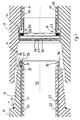
- FIG. 1 shows opposing ends of two adjacent drill pipe sections 10,12.
- One drill pipe 12 has a female receiving thread 16, which is engaged by rotation of the corresponding male thread 14 of the other drill pipe 10.
- Each drill pipe has three bores drilled longitudinally inside the drill pipe wall, equally spaced around the radius of the drillpipe section (when spaced at 120° around the radius of the drill pipe, a longitudinal section taken centrally through the drill pipe section would not show two bores; two bores 20, 22 are here shown to better illustrate the nature of the connections).
- the bore 20 opens at the male end at a region 25 forward of (considering forward to be towards the right in the figure) and proximal to the thread 14.
- a conductor 21 is introduced into this bore 20. Space or other considerations within the drill pipe, and its wall cavity, wall may require the conductor 21 to have an aspect ration not equal to one.
- aspect ratio is the measurement of the overall length of the conductor divided by the measurement of the overall width of the conductor.
- a conductor 21 with a circular cross-sectional area would have equal length and width measurements, and thus would have an aspect ration equal to one.
- a conductor 21 that is rectangular in cross-sectional area would have a length measurement greater than a width measurement, consequently this conductor would have an aspect ratio greater than one.
- a male connector 30 is attached, the conductor 21 terminating in this male connector. If necessary, a recess is provided to accept the male connector 30.
- the male connector is annular, and includes three annular conductive rings 35, 36, 37 having surfaces exposed on the outer circumference of the male connector. Each of the three conductive rings are connected respectively to one of the three conductors. A metal sealing ring 38 is also included in the male connector.
- the drill pipe 12 also features three longitudinal bores (40, 42 being visible here) which emerge at the female end of the drill pipe forward of (again considering forward to be towards the right in the figure) and proximal to the thread 16.
- the bores 40, 42 include conductors 41, 43.
- a female connector 50 is attached, the conductor terminating in this female connector.
- a recess 51 is provided to accept the female connector 50.
- the female connector is annular, and includes three annular conductive rings 56, 57, 58 having surfaces exposed on its inner circumference. Each of the three conductive rings are connected respectively to one of the three conductors.
- the female connector includes a radial shoulder 53, this shoulder having a metal sealing surface 54. Incorporated in the radial shoulder is an annular seal 59, such as an elastomeric seal.
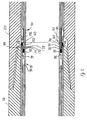
- the metal sealing ring 38 of the male connector compresses the annular seal 59 of the female connector until the metal sealing ring 38 abuts the female connector's metal sealing surface 53, sealing the conductive rings from inner wellbore fluid
- the annual seal is elastomeric in nature.
- the components of the female connector 50 lie substantially flush with the inner surface of the drill pipe section's central throughbore 70.
- the three conductive rings 35, 36, 37 of the male connector now lie in conjunction with the three conductive rings 56, 57, 58 of the female connector.
- These connections are sealed on the one hand by the metal to metal seal between the male connector's sealing ring 38 and female connector metal sealing surface 53, augmented by the annular seal 59 which is energised by the metal sealing ring 38, and on the other hand by the mating threads 14, 16 of the male and female ends of the adjacent drill pipe sections.
- An o-ring seal 11 is included in the shoulder 13 of the male end of the drill pipe section 10.
- Each drill pipe section includes both a male end and a female end having respectively male connector and female connector as described, the conductors disposed in the bores running the entire length of each drill pipe section. As these drill pipe sections are made up into a drill string, three conductive paths along the drill string are formed.
- the drill pipe section's longitudinal bores 20, 22, 40, 42 ideally run parallel to the drill pipe sections' axes.
- the mating threads 14, 16 may not engage to the same position as when they were initially made up.
- the drill pipe sections' ends may be shortened and/or rethreaded.
- the male and female connectors 30, 50 will therefore have to be repositioned, and accommodating recesses/profiles in the drill pipe sections have to be remilled.
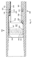
- the central throughbore of a drill pipe section typically includes a widened middle region 72 between to relatively narrow end regions 73, 74, the end regions having a greater thickness of material to give additional strength in the area where the drill pipes are joined. It may not therefore be possible to produce a straight longitudinal bore along the entire length of the drill pipe section without impinging upon the drill pipe section's threads.
- two aligned bores 80, 81 are drilled into the drill pipe section, and a tube of resilient material 85 is attached in a sealed manner between the facing mouths 83, 84 of the two bores to form an enclosed bore running the length of the drill pipe section.
- the drill pipe section's bores are filled with oil. As the environmental pressure in the vell bore hole is increased, this oil may be pressurised in order to equalise the pressure between the connection with the external pressure and so reduce the stress exerted on the seals.
- the resilient material 85 connected between the facing mouths 83, 84 is compressed in response to increasing external pressure, reducing the volume of the bore 80, 81, increasing the bore's pressure and thus reducing the pressure difference.
- the equalisation of the bore's pressure could be alternatively or additionally be achieved using, for example, a pressure gauge and actuator mechanism
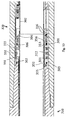
- the male connector 91 installed in a drill pipe section 110 includes two forward facing collars 91, 92.
- annular cavity if formed between the two forward facing collars 91, 92 of the male connector 30.
- annular seal 95 biased by a spring 96 to be held covering the surface of the conductive rings 36, 37, 38.
- the inner collar 92 extends further from the male connector than the outer collar 91.
- the outer collar includes a ledge 98 which, in conjunction with the drill pipe, forms a circular groove 99.
- the adjacent drill pipe section 120 is similar to the drill pipe section 110 just described, and includes three longitudinal bores 140, 142 (only two of which are visible here) located near the inner surface of the drill pipe section.
- the bores rather than being integrally formed in the wall of the drill pipe section, are provided in a lining, or inner sleeve.
- the conductors are here formed between two coaxial tubes, the conductors being semi-cylindrical elements of similar curvature to the tubes, such that the three conductors can be placed axially upon the inner tube, with spacer means between each conductor, each conductor subtending some angle less than 120° of the tube's circumference.
- the outer tube is then affixed to the inner tube, and the assemble is then secured in the drill pipe section.
- the conductor assembly may be formed in part by an extrusion process, the inner tube being formed using a gas impermeable metal tube, or sleeve, 223 the outer surface of which is coated by extrudate 224, the conductors 120 being affixed to the coated inner tube, and the inner tube and conductors 120 being coated again in another extrusion stage 225 to cover and hold the conductors 120 in a spaced relationship.
- This assembly may now be introduced to the drill pipe section 110.
- the inner sleeve shields the conductors from wellbore fluid.
- the three semi-cylindrical conductors 120 are each respectively connected to one of the three conductive rings 36, 37, 38 present in the female connector described below.
- a portion of the inner surface of the drill pipe at the female end is removed to create a profile 103.
- the lining may be made up of layers 104, 105, 106 to form the profile; it will be noted that the profile of the male end of the inner surface is the complement of the profile of the female end of the inner surface, so the profile may be achieved by using similar layers of material, with the different layers being axially displaced to create the profile.
- This profile 103 engages with a female end connector 100. When one side of the drill string is considered in section as shown here, a recess is milled into the drill pipe.
- the female end connector includes, considering a half section portion, two forward facing collars 134, 135, one of which, the outer collar 134, abuts an inner portion 133 of the drillpipe section 120, and one of which, the inner collar 135, both engages with the recess in the profile 103 and features a shoulder 137 abuts the inner portion of the drill pipe section.
- the female connector includes three bores 150, 152 similar to those 140, 142 in the drill pipe section 120, these bores being less radially displaced. Conductors run through the bores of the female connector, each conductor being connected via a contact element 151, 153 to the corresponding conductor of drill pipe section.
- the female connector also includes two backward facing collars 131, 132.
- Three axially spaced conductive rings 171, 172, 173 are situated on the outer surface of the cylinder formed by the inner collar 132.
- the three conductors of the female connector are each respectively connected to one of the three rings.
- An annular cavity 136 is formed between the two backward facing collars 131, 132 of the female connector.
- an annular seal 160 biased by a spring 161 to be held covering the surface of the conductive rings.
- the inner collar 132 includes a shoulder 163 on its inner diameter.
- the annular seal 160 and its spring 161 are displaced deeper into the cavity. As it is displaced, the seal 160 wipes the surface of the conductive rings 171, 172, 173, ensuring that a good contact will be formed. Simultaneously, the outer collar 131 of the female connector displaces the male connector's annular seal 95, wiping the male connector's conductive rings 36, 37, 38. When the male and female connector's are fully engaged, the three conductive rings 36, 37, 38 of the male connector and the three conductive rings 171, 172, 173 of the female connector slide into conjunction so as to form three conductive paths from the drill pipe 110 to the adjacent drill pipe 120.
- Each drill pipe section thus features a male connector and female connector as described, so that a three conductive circuits down the length of the drill pipe are produced.
- the bores are oil filled in order that they may be balanced with the external pressure.
- This pressure is set such that it does not stress the seals when the environmental pressure is low, but is sufficient to afford protection to the seals when the environmental pressure is high.
- a weep hole may instead be provided. It will be realised that position of the pressure release valve may be varied, for example it could be included at the female end of drill pipe section 12 backward of the female thread, venting excess lubricating grease outside the drill string.
- three conductors 21 are longitudinally disposed in a laminate tubular member 108.
- the tubular member may be formed partly by extrusion, for example using a steel tube 223 having an insulating layer 224, the conductors 21 then being set with another insulating layer 225.
- the tubular member is then inserted in the drill pipe section 110.
- the tubular member may be formed to follow the inner surface of the drill pipe section, for example being swaged to follow the widened portion commonly present in the mid-section of drill pipe sections.
- the drill pipe section's longitudinal bores 20, 22, 40, 42 ideally run essentially parallel to the drill pipe sections' axes.
- the mating threads 14, 16 may not engage to the same position as when they were initially made up.
- the drill pipe sections' ends may be shortened and/or rethreaded.
- the male and female connectors 30, 50 will therefore have to be repositioned, and accommodating recesses/profiles in the drill pipe sections have to be re-milled.
- the conductive rings 311, 312, 313 of the male threaded end are brought into contact with the conductive rings 331, 332, 333 of the female thread end module 330, the garter springs of the male threaded end pressing against the female thread end module's conductive rings 331, 332, 333 to ensure a good electrical contact is made.
- the liner tubes 302 of the two drill pipe sections meet to form a continuous throughbore, although they need not.
Abstract
Description
- The present invention relates to the transmission of power and data within a well bore, in particular, through a drillstring.
- When drilling a borehole, or performing operations to maintain the borehole or operations associated with the production of oil or gas, it is often desirable to transmit power to various downhole devices, such as drill bits and traction tools. Various instruments can also be included on a drill string in order to gather data concerning the structure of the environment of the borehole, and the performance of the borehole operations and downhole devices. It is advantageous for this data to be transmitted back to the surface along an electrical conductor.
- In one type of cabling system, shown in US3879097, US3518609, US4557538, US6123561 and DE 1189934, each drill pipe section includes one or more conductors, each conductor having a contact at each end of the section. When the drill pipe sections are made up in a drill string, the contacts of adjacent drill pipe sections abut and a circuit is formed over the drill string.
- Such systems are vulnerable to poor connections between the abutting contacts. Ideally contact rings should be clean, and a specialised non-conductive "pipe dope" or joining compound (which is more expensive than standard pipe dope) must be used in order not to short the connection. Another disadvantage of this system is that the connection between the conductor and the contact are subjected to borehole pressure and are susceptible to fail.
- The object of the present invention is to provide an apparatus and method for conveniently and reliably disposing cabling in a drill string.
- According to the present invention there is provided a generally tubular drill pipe having a conductive path over a plurality of drill pipe sections, each drill pipe section having a first end and a second end, and having a wall, and the first end having a first radial sealing surfaces and the second end having a corresponding second radial sealing surfaces, such that when the first or second end of one drill pipe section is engaged with the second or first end respectively of another drill pipe section, at least one seal is formed, wherein a conductor is connected to a first contact means at one end and a plug at the other end, and, wherein ingress protection means are provided to protect the contact means from ingress from inside or outside of the drill pipe section.
- A drill pipe section is generally tubular and therefore has a central throughbore often used for the passage of well fluids. The present invention may also include bores formed or situated in the walls of drill pipe sections; and reference to bores refers to these wall bores, whereas the main bore of the drill pipe is identified as the central throughbore.
- A telemetering system will now be described, by way of example, with reference to the drawings, of which;
- FIG. 1 is a longitudinal sectional view of two facing ends of adjacent drill pipe sections in a disengaged state;
- FIG. 2 is a longitudinal sectional view of two facing ends of adjacent drill pipe sections when engaged;
- FIG. 3 is a longitudinal sectional view of the middle portion of a drill pipe section;
- FIG. 4 is a longitudinal sectional view of another embodiment of two facing ends of adjacent drill pipe sections in a disengaged state;
- FIG. 5 is a longitudinal sectional view of this embodiment when engaged;
- FIG. 6 is a longitudinal sectional view of a further embodiment of two facing ends of adjacent drill pipe sections in a disengaged state;
- FIG. 7 is a longitudinal sectional view of this embodiment when engaged;
- FIG. 8 is a longitudinal sectional view of a further embodiment;
- FIG. 9 is a cross sectional view through XX of this embodiment; and
- FIG. 10 is a longitudinal sectional view of part of the embodiment during manufacture.
- FIG. 11 is a longitudinal sectional view of the male end of an another embodiment.
- FIG. 12 is a longitudinal sectional view of the female end of this embodiment showing a module connection.
- FIG. 13 is a longitudinal sectional view of this embodiment when engaged.
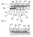
- FIG. 14 is a is a section view an embodiment of the conductive rings when engaged.
- FIG. 15 is a longitudinal sectional view of the previous female end module.
- FIG. 16 is a longitudinal sectional view of a further embodiment of two facing ends of adjacent drill pipe sections when engaged.
- FIG. 1 shows opposing ends of two adjacent
drill pipe sections drill pipe 12 has afemale receiving thread 16, which is engaged by rotation of the correspondingmale thread 14 of theother drill pipe 10. Each drill pipe has three bores drilled longitudinally inside the drill pipe wall, equally spaced around the radius of the drillpipe section (when spaced at 120° around the radius of the drill pipe, a longitudinal section taken centrally through the drill pipe section would not show two bores; twobores - The
bore 20 opens at the male end at aregion 25 forward of (considering forward to be towards the right in the figure) and proximal to thethread 14. Aconductor 21 is introduced into thisbore 20. Space or other considerations within the drill pipe, and its wall cavity, wall may require theconductor 21 to have an aspect ration not equal to one. As herein defined, when viewing the cross-sectional area of aconductor 21, aspect ratio is the measurement of the overall length of the conductor divided by the measurement of the overall width of the conductor. As an example, aconductor 21 with a circular cross-sectional area would have equal length and width measurements, and thus would have an aspect ration equal to one. Aconductor 21 that is rectangular in cross-sectional area would have a length measurement greater than a width measurement, consequently this conductor would have an aspect ratio greater than one. - Where the bore opens at the male end of the
drill pipe section 10, amale connector 30 is attached, theconductor 21 terminating in this male connector. If necessary, a recess is provided to accept themale connector 30. The male connector is annular, and includes three annularconductive rings metal sealing ring 38 is also included in the male connector. - The
drill pipe 12 also features three longitudinal bores (40, 42 being visible here) which emerge at the female end of the drill pipe forward of (again considering forward to be towards the right in the figure) and proximal to thethread 16. As for thebores drill pipe 10, thebores conductors drill pipe section 12, afemale connector 50 is attached, the conductor terminating in this female connector. If necessary, arecess 51 is provided to accept thefemale connector 50. The female connector is annular, and includes three annularconductive rings radial shoulder 53, this shoulder having a metal sealing surface 54. Incorporated in the radial shoulder is anannular seal 59, such as an elastomeric seal. - Referring to FIG. 2, when the
male thread 14 ofdrill pipe 10 is introduced into the female end ofdrill pipe 12, themetal sealing ring 38 of the male connector compresses theannular seal 59 of the female connector until themetal sealing ring 38 abuts the female connector'smetal sealing surface 53, sealing the conductive rings from inner wellbore fluid Preferably, the annual seal is elastomeric in nature. The components of thefemale connector 50 lie substantially flush with the inner surface of the drill pipe section'scentral throughbore 70. - The three
conductive rings conductive rings ring 38 and female connectormetal sealing surface 53, augmented by theannular seal 59 which is energised by themetal sealing ring 38, and on the other hand by themating threads ring seal 11 is included in theshoulder 13 of the male end of thedrill pipe section 10. Thus the contacting conductive rings are not exposed to the corrosive components usually present in well fluid. - Each drill pipe section includes both a male end and a female end having respectively male connector and female connector as described, the conductors disposed in the bores running the entire length of each drill pipe section. As these drill pipe sections are made up into a drill string, three conductive paths along the drill string are formed.
- The drill pipe section's
longitudinal bores mating threads female connectors longitudinal bores - Referring to FIG. 3, the central throughbore of a drill pipe section typically includes a widened
middle region 72 between to relativelynarrow end regions bores resilient material 85 is attached in a sealed manner between the facingmouths 83, 84 of the two bores to form an enclosed bore running the length of the drill pipe section. - The drill pipe section's bores are filled with oil. As the environmental pressure in the vell bore hole is increased, this oil may be pressurised in order to equalise the pressure between the connection with the external pressure and so reduce the stress exerted on the seals. The
resilient material 85 connected between the facingmouths 83, 84 is compressed in response to increasing external pressure, reducing the volume of thebore - Referring to FIG. 4, in an alternative embodiment the
male connector 91 installed in adrill pipe section 110 includes two forward facingcollars - An annular cavity if formed between the two forward facing
collars male connector 30. In this cavity is anannular seal 95, biased by aspring 96 to be held covering the surface of the conductive rings 36, 37, 38. Theinner collar 92 extends further from the male connector than theouter collar 91. The outer collar includes aledge 98 which, in conjunction with the drill pipe, forms acircular groove 99. - The adjacent
drill pipe section 120 is similar to thedrill pipe section 110 just described, and includes threelongitudinal bores 140, 142 (only two of which are visible here) located near the inner surface of the drill pipe section. In this embodiment, the bores, rather than being integrally formed in the wall of the drill pipe section, are provided in a lining, or inner sleeve. The conductors are here formed between two coaxial tubes, the conductors being semi-cylindrical elements of similar curvature to the tubes, such that the three conductors can be placed axially upon the inner tube, with spacer means between each conductor, each conductor subtending some angle less than 120° of the tube's circumference. The outer tube is then affixed to the inner tube, and the assemble is then secured in the drill pipe section. - Referring FIG. 4a, the conductor assembly may be formed in part by an extrusion process, the inner tube being formed using a gas impermeable metal tube, or sleeve, 223 the outer surface of which is coated by
extrudate 224, theconductors 120 being affixed to the coated inner tube, and the inner tube andconductors 120 being coated again in anotherextrusion stage 225 to cover and hold theconductors 120 in a spaced relationship. This assembly may now be introduced to thedrill pipe section 110. In general, the inner sleeve shields the conductors from wellbore fluid. - The three
semi-cylindrical conductors 120 are each respectively connected to one of the threeconductive rings - A portion of the inner surface of the drill pipe at the female end is removed to create a profile 103. If a lining or sleeve is used, the lining may be made up of
layers female end connector 100. When one side of the drill string is considered in section as shown here, a recess is milled into the drill pipe. The female end connector includes, considering a half section portion, two forward facingcollars outer collar 134, abuts aninner portion 133 of thedrillpipe section 120, and one of which, theinner collar 135, both engages with the recess in the profile 103 and features a shoulder 137 abuts the inner portion of the drill pipe section. The female connector includes threebores drill pipe section 120, these bores being less radially displaced. Conductors run through the bores of the female connector, each conductor being connected via acontact element 151, 153 to the corresponding conductor of drill pipe section. - The female connector also includes two backward facing
collars conductive rings inner collar 132. The three conductors of the female connector are each respectively connected to one of the three rings. - An
annular cavity 136 is formed between the two backward facingcollars annular seal 160, biased by aspring 161 to be held covering the surface of the conductive rings. Theinner collar 132 includes ashoulder 163 on its inner diameter. - Referring to FIG. 5, when the male end of the
drill pipe section 110 is fully engaged with the female end of the adjacentdrill pipe section 120, themale connector 90 andfemale connector 100 also engage. Specifically, the forward facingouter collar 91 of themale connector 90 engages in thecavity 136 between the backward facinginner collar 132 andouter collar 131 of thefemale connector 100, and theouter collar 131 of the female connector engages in the cavity between the forward facinginner collar 92 andouter collar 91 of the male connector. Theouter collar 131 of the female connector is accommodated in thecircular groove 99 formed between theouter collar 91 of the male connector and thedrill pipe 110. Theinner collar 92 of the male connector abuts theshoulder 163 of the outerinner collar 132 of the female connector. Thus, the male 90 and female 100 connectors engage to produce an inner surface flush with each other and the drill pipe surface of the central throughbore sections in they are installed. - As the outer
forward facing collar 91 of the male connector enters thecavity 136 of the female connector, theannular seal 160 and itsspring 161 are displaced deeper into the cavity. As it is displaced, theseal 160 wipes the surface of theconductive rings outer collar 131 of the female connector displaces the male connector'sannular seal 95, wiping the male connector's conductive rings 36, 37, 38. When the male and female connector's are fully engaged, the threeconductive rings conductive rings drill pipe 110 to theadjacent drill pipe 120. - The outer surface of the male connector's
inner collar 92 includes an o-ring seal 190, which seals against the female connector'sinner collar 131. Similarly, the outer surface of the male connector'souter collar 92 includes an o-ring seal 191, which seals against the female connector'souter collar 131. - Each drill pipe section thus features a male connector and female connector as described, so that a three conductive circuits down the length of the drill pipe are produced. As in the previous example, the bores are oil filled in order that they may be balanced with the external pressure.
- Referring to FIGS. 6 and 7, the male end of the
drill pipe section 10 includes apressure release valve 165 forward of theshoulder 13. When thedrill pipe sections elastomeric seals female connectors shoulder 13 of the male end ofdrill pipe section 10 and theend 15 of the female end ofdrill pipe section 12, and theelastomeric seal 11 on the other hand. The pressure release valve allows excess lubricating grease to escape when a certain pressure is reached. This pressure is set such that it does not stress the seals when the environmental pressure is low, but is sufficient to afford protection to the seals when the environmental pressure is high. Rather than a pressure release valve, a weep hole may instead be provided. It will be realised that position of the pressure release valve may be varied, for example it could be included at the female end ofdrill pipe section 12 backward of the female thread, venting excess lubricating grease outside the drill string. - Referring to FIG. 8 specifically, and generally to FIGS. 8-15, three conductors 21 (here of the semi-cylindrical type as previous described) are longitudinally disposed in a laminate tubular member 108. As previously described, the tubular member may be formed partly by extrusion, for example using a
steel tube 223 having an insulatinglayer 224, theconductors 21 then being set with another insulatinglayer 225. The tubular member is then inserted in thedrill pipe section 110. The tubular member may be formed to follow the inner surface of the drill pipe section, for example being swaged to follow the widened portion commonly present in the mid-section of drill pipe sections. The at a region forward of the male thread of the drill pipe section three radial apertures 201 (only one of which is visible) are bored through the drill pipe section, equally spaced around the circumference of the drill pipe section and each one somewhat displaced axially, corresponding to the axial displacement of theconductive rings radial conductor 203 and surroundinginsulator 204 is set in each aperture, eachradial conductor 204 being in contact with one of the axially disposedconductors conductor 203 protrudes from theinsulator 204, so that when the conductive rings are fitted the relevantconductive ring 181 is pressed against the protrudingconductor 203 to ensure a good conductive path. This radial conductor is also shown in FIG. 9. - The female end of the
drill pipe section 112 includes similar radial conductors 206 (only on of which is visible), again set in aradial bore 205 using aninsulator 207. Theradial conductors 206 are connected to a conductingelements 230 set in an insulatingcollar 231. Each conductingelement 230 is attached to aconductive ring drill pipe section 110 is inserted into the female end ofdrill pipe section 112, theseconductive rings conductive rings - This embodiment includes radial metal to metal seals where the hindmost (hindmost being to the left in the figure) part of
female thread 210 abuts theshoulder 211 behind the male thread, and the foremost part of themale thread 212 abuts ashoulder insert 213 in front of the female thread. In addition, and o-ring 215 is provided between the male and female threads, and further o-rings conductive rings - As previously mentioned, the volume between the inner and outer sets of seals are preferably filled with non-conductive lubrication grease or 'pipe dope'. This grease is substantially incompressible, and is also pressurised as the male and female parts are screwed together (and, as previously mentioned, a pressure release valve may be included). If a seal does fail, the penetration of the well bore fluids will be reduced or eliminated by the presence of the grease in the previously sealed volume, since the fluids will only continue to penetrate the volume until while the pressure of the grease is less than that of the fluids ; when the pressures are equalised the fluid penetration will cease, and, since the grease is substantially incompressible, the conductive contacts will not have been exposed but will still be enveloped by the grease. To the extent that some of the sealed volume cannot be filled with grease, or to the extent that the grease is compressible, a grease reservoir may be included one or both sides of the electrical contacts to ensure that grease remains around the contacts even after the grease has been displaced or compressed. Adjoining drill pipe sections could be provided with just a single seal, so that the electrical contact portions (the conductive rings, radial conductors etc.) are open to well bore fluids, but that the volume between the seal and the electrical contacts, and extending somewhat beyond these electrical contacts, is filled with substantially incompressible grease.
- Drill pipe sections may also include a by-
pass duct 240, as shown in FIG. 8, which extends from one side of the contacts to the other so that any pressure difference arising between the inside of the drill pipe and the voids in the thread, or due to any leakage of one of the seals, or if only one seal is provided will result in fluids by-passing the contact zone equalising the pressure either side of the electrical contacts without displacing the grease covering the contacts - The
radial conductors 206,conductive elements 230 andconductive rings - Referring to FIG. 11, in a modified embodiment, an inserted
liner tube 302 extends through thedrill pipe section 300. At themale thread end 310, anelastomeric nose seal 304 is located around the outer surface of the liner tube. Situated behind the nose seal (that is, to the left in the drawing) around the liner tube is abypass collar 306. The bypass collar may be attached to the liner by laser weld. Thenose seal 304 engages with thebypass collar 306. Around thebypass collar 306 are threeconductive rings material 315, preferably an elastomer or ceramic. Each ring includes a radially inwardly extending portion 316 (only one here being visible). As in embodiments previously described, threeconductors 318 extend along an annulus in the drill pipe between the inner surface of the drill pipe section and the inner liner tube, each conductor occupying some part of a 120° portion of the drill string's circumference. As noted above, the conductors preferably have a rectangular cross-sectional area. When therings male thread end 310 each of the inwardly extendingportions 316 clamps on the end of a respectiveannular conductors 318. This embodiment could be implemented with axially running conductors disposed in a bore drilled in the wall of the drill string (that is, dispensing with some or all of the liner tube) as previously described. - Referring also to FIG. 14, the outer curved surface of each
conductive ring male thread end 310 includes an annular groove wherein an outer conductor, or resilient member, ring is disposed. This resilient member may consist of aconductive garter spring - Two o-
ring seals bypass collar 306 includes a portion that extends somewhat into the annular region between the drill string and the liner tube, the bypass collar included abypass channel 352 which communicates, via aradially extending port 354 through thebypass collar 306, with the environment forward of theconductive rings ring 301, and, via aradially extending port 355 through the an adjacent part of the drill string, to the environment behind the conductive rings and rear o-ring 303. - Referring again to FIG. 2, the drill pipe section's
longitudinal bores mating threads female connectors end 320 shown in FIG. 12, theliner tube 302 extends along the bore of the drill string section past theinternal recess shoulder 321 of the female thread end. Eachannular conductor 318 is terminates at aplug 319 adjacent to the internal recess shoulder. Theplugs 319 are set in insulatingmaterial 323, such as an elastomer. Set into theinternal recess shoulder 321 is at least one retaining threadedinsert 325. - Shown is a representative female end module, the module being selectively removable. Although not shown, a male end module of a similar nature is also envisioned and included herein. A female
thread end module 330 is fitted to thefemale thread end 320, a portion of the femalethread end module 330 inserted to extend between theliner tube 302 and the inner surface of thedrill string section 300. The femalethread end module 330 includes threesockets 329, which respectively engage with the threeplugs 319 connected to theannular conductor 318. At the end of the femalethread end module 330 proximal to the female opening, are located threeconductive rings conductive rings male end 310 of the adjacent drill string section. Each of theconductive rings conductive lines 317 to theplugs 319. The rings and plugs are set in an insulating material 324. Abutting the edge of theliner tube 318, a sealingmember 334 includes o-rings 336 that seal the femalethread end module 330 against theliner tube 318. A bore extends through the sealing member and insulating material so that a screw, such as an extendedsocket head screw 338 engaging with the retaining threadedinsert 325 retains the femalethread end module 330 in the female thread end. A distance between theconductive rings liner tube 302 is provided for the accommodation of themale thread end 310. As described herein, a module connector arrangement facilitates quicker and less expensive rebuilds and repairs. - Referring to FIG. 13, when the individual drill pipes are joined, the male threaded
portion 310 of one drill string section being inserted into the female threadedportion 320 of an adjacent drill pipe section, theconductive rings conductive rings thread end module 330, the garter springs of the male threaded end pressing against the female thread end module'sconductive rings liner tubes 302 of the two drill pipe sections meet to form a continuous throughbore, although they need not. The electrical components are sealed against the inner bore of thedrill string 300 by the o-rings 336 of the female thread end module's sealing member and the nose seal and bypass collar forward o-rings 301 of the male thread end. Similarly, the electrical components are sealed against the environment outside the drill string by the rear o-ring 303 of the male thread end. Non-conductive pipe dope is applied to the threads prior to joining, and some of this pipe dope is retained in a pressurised state in a small volume between the end of the femalethread end module 330 themale thread 310 of the adjacent drill pipe. Thebypass channel 352 communicates with this volume via one of the bypass ports. It will be seen, in a similar manner to previous embodiments, that theseals - Referring to FIG. 14, wiper o-
rings conductive rings conductive rings rings metallic portion 350 extends from theannular conductor 318 into an aperture this part of the conductive ring. Agrub screw 351 then ensures a good electrical contact with the flat portion of theannular conductor 350. Thegarter spring 341 rests upon the head of thegrub screw 351, as well as pressing upon theconductive ring 331 of the femalethread end module 330. - When drill string joints are to be reused, the female thread may be worn and it is often desirable to re-cut the thread. As part of the process, a part of the of the
female thread end 320 is removed (typically 2 cm or 3/4 of an inch). Referring to FIGS. 15a to 15c, to accommodate this process, the femalethread end module 330 is removed, and the length of theliner tube 302 is reduced by the distance that thefemale thread end 320 is to be reduced by (or theliner tube 302 is replaced by a correspondingly shorter liner tube.) A new femalethread end module 330 having a reduced distance between thesocket 329 and the sealingmember 334 is then introduced to thefemale thread end 320, so that the distance between the end of the female thread and the female thread end module'sconductive rings socket head screw 338 length is either shortened or replaced with a shorter screw. Thefemale thread end 320 may be re-cut on several occasions, with correspondingly shorter femalethread end modules 330 being used after each re-cutting operation. The male thread end may also be re-cut; in this case, theliner tube 302 will again have to be re-sized, theannular conductors 318 shortened and reconnected, and a fresh bypass bore 335 drilled through themale end 310 of the drill pipe section. - Referring to FIG. 16, in a modified embodiment, a
box sealing carrier 404 is inserted into the box end of thedrill pipe 400. Thebox sealing carrier 404 is preferably metallic in nature, and contains anannular groove 410 on its innermost surface (that is, to the left in the drawing). Thisannular groove 410 is designed to receive ametal gasket ring 411, such as a type R ring gasket. The box to box sealing carrier connection, with themetallic gasket 411 disposed in between, forms a soft metal seal. Thebox sealing carrier 404 is preferably attached to the box end of thedrill pipe 400 by means of a screw or bolt (numeral 402 referring to a bolt hole or screw cavity). Such attachment method yields to easy removal, repair, and replacement. - As shown, the
conductor 408 travels through the bore and through apassageway 412 in thebox sealing carrier 404, opening to anannulus 414 proximate to the first conductive rings (firstconductive ring carrier 416 is shown in the Figure). Also disposed within the box sealing carrier is anannular groove 407 designed to carry anelastomer seal 406 in order to further seal the conductive rings from wellbore fluid. Thiselastomer seal 406 is referred to as an internal electric contact seal. The internal electric contact seal is located in contact with thebox sealing member 404 and the box shoulder or collar area. Preferably too, the internal electric contact seal is capable of being energized to further seal the conductive rings from internal wellbore fluid. - The provision of three conductors means that a three phase power supply may be transmitted down the drill string. Naturally, fewer or further conductive paths may be provided using the principles described herein. In particular, a telemetry wireline may be provided over such a conductive path.
Claims (8)
- A generally tubular drill pipe having a conductive path over a plurality of drill pipe sections (300), each drill pipe section having a first end (310) and a second end (320), and having a wall, and the first end having a first radial sealing surfaces (304) and the second end having a corresponding second radial sealing surfaces (334), such that when the first or second end of one drill pipe section is engaged with the second or first end respectively of another drill pipe section, at least one seal is formed, and having a conductor conected to a first contact means (311) at its first end characterised in that the conductor is connected to a plug (319) at its second end, and, wherein ingress protection means (302) are provided to protect the contact means from ingress from inside or outside of the drill pipe section.
- A drill pipe according to claim 1 wherein the plug connects to a module by means of an electrical socket (329).
- A drill pipe according to claim 2 wherein the module contains a second contact means (331).
- A drill pipe according to claim 3 wherein the first contact means and the second contact means are provided by corresponding conductive rings coaxial with the drill pipe.
- A drill pipe according to claim 4 wherein the wall includes within it at least one bore, the bore having a conductor disposed inside it, and this conductor being connected to a first conductive ring at the first end, and a plug at the second end, wherein the plug is capable of receiving a module therein containing an equal number of conductive rings, such that when the first or second end of one drill pipe section is engaged with the second or first end respectively of another drill pipe section, the conductive connections are formed in the sealed volume to provide conductive paths over the plurality of drill pipe sections.
- A drill string according to claim 4 wherein the first three conductive rings are axially spaced, and the second three conductive rings are axially spaced.
- A drill string according to claim 6 wherein the first three conductive rings are notched to receive an outer ring conductor, such that the conductive connections consist of the first three conductive rings in contact with the outer ring conductor.
- A drill string according to claim 7 wherein the outer ring conductor comprises an annular spring (341).
Applications Claiming Priority (3)
| Application Number | Priority Date | Filing Date | Title |
|---|---|---|---|
| GBGB0115524.1A GB0115524D0 (en) | 2001-06-26 | 2001-06-26 | Conducting system |
| GB0115524 | 2001-06-26 | ||
| PCT/GB2002/002933 WO2003001023A1 (en) | 2001-06-26 | 2002-06-26 | Electrical conducting system |
Publications (2)
| Publication Number | Publication Date |
|---|---|
| EP1407111A1 EP1407111A1 (en) | 2004-04-14 |
| EP1407111B1 true EP1407111B1 (en) | 2007-03-21 |
Family
ID=9917324
Family Applications (1)
| Application Number | Title | Priority Date | Filing Date |
|---|---|---|---|
| EP02751296A Expired - Lifetime EP1407111B1 (en) | 2001-06-26 | 2002-06-26 | Electrical conducting system |
Country Status (9)
| Country | Link |
|---|---|
| US (1) | US7114970B2 (en) |
| EP (1) | EP1407111B1 (en) |
| AT (1) | ATE357578T1 (en) |
| AU (1) | AU2002349873B2 (en) |
| CA (1) | CA2451358C (en) |
| DE (1) | DE60219017D1 (en) |
| GB (1) | GB0115524D0 (en) |
| NO (1) | NO329260B1 (en) |
| WO (1) | WO2003001023A1 (en) |
Families Citing this family (51)
| Publication number | Priority date | Publication date | Assignee | Title |
|---|---|---|---|---|
| US20070056155A1 (en) * | 2002-09-13 | 2007-03-15 | Reimert Larry E | Method of installing flange on tubular body at desired elevation |
| US20060033638A1 (en) * | 2004-08-10 | 2006-02-16 | Hall David R | Apparatus for Responding to an Anomalous Change in Downhole Pressure |
| FR2881172B1 (en) * | 2005-01-25 | 2008-03-14 | Deviatec Sarl | TUBULAR DRILLING ROD |
| US7277026B2 (en) * | 2005-05-21 | 2007-10-02 | Hall David R | Downhole component with multiple transmission elements |
| US7291028B2 (en) * | 2005-07-05 | 2007-11-06 | Hall David R | Actuated electric connection |
| US7649475B2 (en) * | 2007-01-09 | 2010-01-19 | Hall David R | Tool string direct electrical connection |
| US7605715B2 (en) | 2006-07-10 | 2009-10-20 | Schlumberger Technology Corporation | Electromagnetic wellbore telemetry system for tubular strings |
| AU2011253677B2 (en) * | 2006-08-23 | 2012-01-12 | Baker Hughes Incorporated | Annular electrical wet connect |
| GB2477052B (en) * | 2006-08-23 | 2011-09-28 | Baker Hughes Inc | Annular electrical wet connector |
| US7644755B2 (en) * | 2006-08-23 | 2010-01-12 | Baker Hughes Incorporated | Annular electrical wet connect |
| CA2572755A1 (en) * | 2007-01-03 | 2008-07-03 | Ken Shipalesky | Wire-line connection system |
| EP2109920B1 (en) * | 2007-02-05 | 2014-11-19 | Quick Connectors, Inc. | Down hole electrical connector for combating rapid decompression |
| EP2156015B1 (en) * | 2007-06-08 | 2013-02-06 | Intelliserv International Holding, Ltd | Repeater for wired drill pipe |
| US20090038849A1 (en) * | 2007-08-07 | 2009-02-12 | Schlumberger Technology Corporation | Communication Connections for Wired Drill Pipe Joints |
| US7806191B2 (en) * | 2007-12-27 | 2010-10-05 | Intelliserv, Llc | Communication connections for wired drill pipe joints for providing multiple communication paths |
| SG155158A1 (en) * | 2008-03-06 | 2009-09-30 | Vetco Gray Inc | Integrated electrical connector for use in a wellhead tree |
| BRPI0910578B1 (en) | 2008-04-08 | 2019-04-09 | Intelliserv International Holding, Ltd. | SYSTEM FOR USE IN A WELL, METHOD FOR FORMING A WIRE CONNECTED DRILL PIPE, AND CABLE CONNECTION FOR USE IN COMBINATION WITH A DRILL PIPE |
| EP2350697B1 (en) | 2008-05-23 | 2021-06-30 | Baker Hughes Ventures & Growth LLC | Reliable downhole data transmission system |
| US7887354B2 (en) * | 2008-08-11 | 2011-02-15 | Holliday Randall A | Thread lock for cable connectors |
| US7857644B2 (en) * | 2008-09-25 | 2010-12-28 | Intelliserv, Llc | Wired drill pipe having conductive end connections |
| US7900708B2 (en) | 2008-10-24 | 2011-03-08 | Marcel Obrejanu | Multiple-block downhole anchors and anchor assemblies |
| US8154316B2 (en) | 2008-12-11 | 2012-04-10 | Fluke Corporation | Method and apparatus for indexing an adjustable test probe tip |
| US7902848B2 (en) * | 2009-01-09 | 2011-03-08 | Fluke Corporation | Reversible test probe and test probe tip |
| US7880487B2 (en) * | 2009-01-22 | 2011-02-01 | Fluke Corporation | Test lead probe with retractable insulative sleeve |
| US8033329B2 (en) * | 2009-03-03 | 2011-10-11 | Intelliserv, LLC. | System and method for connecting wired drill pipe |
| AT508272B1 (en) * | 2009-06-08 | 2011-01-15 | Advanced Drilling Solutions Gmbh | DEVICE FOR CONNECTING ELECTRICAL WIRES |
| US20110024103A1 (en) * | 2009-07-28 | 2011-02-03 | Storm Jr Bruce H | Method and apparatus for providing a conductor in a tubular |
| FR2967452B1 (en) * | 2010-11-16 | 2012-11-16 | Vam Drilling France | DEVICE FOR ELECTRICAL CONNECTION BETWEEN TUBULAR COMPONENTS OF DRILLING LINING, COMPONENT AND CORRESPONDING JUNCTION |
| ES2470769T3 (en) * | 2011-03-04 | 2014-06-24 | Bauer Maschinen Gmbh | Drilling linkage |
| US8967295B2 (en) * | 2011-08-22 | 2015-03-03 | Baker Hughes Incorporated | Drill bit-mounted data acquisition systems and associated data transfer apparatus and method |
| AT512604B1 (en) * | 2012-03-01 | 2019-05-15 | Think And Vision Gmbh | drill pipe |
| US9322223B2 (en) * | 2012-05-09 | 2016-04-26 | Rei, Inc. | Method and system for data-transfer via a drill pipe |
| US10132123B2 (en) | 2012-05-09 | 2018-11-20 | Rei, Inc. | Method and system for data-transfer via a drill pipe |
| GB2504301B (en) * | 2012-07-24 | 2019-02-20 | Accessesp Uk Ltd | Downhole electrical wet connector |
| SG11201502257XA (en) | 2012-09-27 | 2015-04-29 | Halliburton Energy Services Inc | Enhanced interconnect for downhole tools |
| CA2901066C (en) * | 2013-02-15 | 2019-06-18 | Prysmian S.P.A. | Method for installing of a wet mateable connection assembly for electrical and/or optical cables |
| AT514235B1 (en) | 2013-04-22 | 2020-03-15 | Think And Vision Gmbh | Drill pipe |
| CN103266885A (en) * | 2013-05-15 | 2013-08-28 | 中国石油化工股份有限公司 | Communication relaying nipple while drilling for oil and gas well |
| US9534455B2 (en) * | 2013-07-23 | 2017-01-03 | Baker Hughes Incorporated | Shoulder ring for transmission line and transmission devices |
| BR112017024767B1 (en) | 2015-05-19 | 2023-04-18 | Baker Hughes, A Ge Company, Llc | BOTTOM WELL COMMUNICATION SYSTEMS AND BOTTOM WELL COMMUNICATION EQUIPMENT |
| US10218074B2 (en) | 2015-07-06 | 2019-02-26 | Baker Hughes Incorporated | Dipole antennas for wired-pipe systems |
| US20180202239A1 (en) * | 2015-07-13 | 2018-07-19 | Schlumberger Technology Corporation | Compliant module connections |
| US11296419B1 (en) | 2016-04-29 | 2022-04-05 | Rei, Inc. | Remote recessed reflector antenna and use thereof for sensing wear |
| WO2020123932A1 (en) * | 2018-12-14 | 2020-06-18 | Baker Hughes, A Ge Company, Llc | Electrical downhole communication connection for downhole drilling |
| WO2020222755A1 (en) | 2019-04-29 | 2020-11-05 | Halliburton Energy Services, Inc. | Electrical connector for oil and gas applications |
| US11193339B2 (en) * | 2019-06-28 | 2021-12-07 | Halliburton Energy Services, Inc. | Concentric disconnect tool with multiple electrical conductors |
| US11525531B2 (en) * | 2020-06-16 | 2022-12-13 | Reelwell A.S. | Seal and insulator for pipe having an insulated electrical conductor |
| CN113969752B (en) * | 2020-07-23 | 2023-10-31 | 中国石油天然气股份有限公司 | Underground intelligent injection and production pipe column quick connecting device |
| US11332981B2 (en) * | 2020-07-31 | 2022-05-17 | Halliburton Energy Services, Inc. | Coated electrical connector bands and pressure compensation assemblies for downhole electrical disconnect tools |
| CN112065292B (en) * | 2020-09-09 | 2022-02-18 | 席赫 | Crude oil extraction pipe |
| CN113884792B (en) * | 2021-09-26 | 2023-05-12 | 四川大学 | Center rod end conductive structure and conductive performance testing system |
Family Cites Families (64)
| Publication number | Priority date | Publication date | Assignee | Title |
|---|---|---|---|---|
| US2153883A (en) * | 1936-07-06 | 1939-04-11 | Grant John | Oil well jar |
| US3191677A (en) * | 1963-04-29 | 1965-06-29 | Myron M Kinley | Method and apparatus for setting liners in tubing |
| DE1189934B (en) * | 1963-10-11 | 1965-04-01 | Johann Gruber | Hollow drill rod connection for deep drilling with electrical line |
| US3424244A (en) * | 1967-09-14 | 1969-01-28 | Kinley Co J C | Collapsible support and assembly for casing or tubing liner or patch |
| US3518608A (en) * | 1968-10-28 | 1970-06-30 | Shell Oil Co | Telemetry drill pipe with thread electrode |
| US3518609A (en) * | 1968-10-28 | 1970-06-30 | Shell Oil Co | Telemetry drill pipe with ring-control electrode means |
| US3528498A (en) * | 1969-04-01 | 1970-09-15 | Wilson Ind Inc | Rotary cam casing swage |
| US3616868A (en) * | 1970-01-13 | 1971-11-02 | Rand Engineering Corp | Fluid-actuated impact tool and anvil device having variable choke |
| US3696332A (en) * | 1970-05-25 | 1972-10-03 | Shell Oil Co | Telemetering drill string with self-cleaning connectors |
| US3879097A (en) * | 1974-01-25 | 1975-04-22 | Continental Oil Co | Electrical connectors for telemetering drill strings |
| US4086115A (en) * | 1975-10-16 | 1978-04-25 | Sweet Jr Robert D | Method of making a hockey stick |
| US4121193A (en) * | 1977-06-23 | 1978-10-17 | Shell Oil Company | Kelly and kelly cock assembly for hard-wired telemetry system |
| GB1571677A (en) * | 1978-04-07 | 1980-07-16 | Shell Int Research | Pipe section for use in a borehole |
| US4243112A (en) * | 1979-02-22 | 1981-01-06 | Sartor Ernest R | Vibrator-assisted well and mineral exploratory drilling, and drilling apparatus |
| US4416494A (en) * | 1980-10-06 | 1983-11-22 | Exxon Production Research Co. | Apparatus for maintaining a coiled electric conductor in a drill string |
| ZA823430B (en) * | 1981-05-22 | 1983-03-30 | Coal Industry Patents Ltd | Drill pipe sections |
| US4445734A (en) * | 1981-12-04 | 1984-05-01 | Hughes Tool Company | Telemetry drill pipe with pressure sensitive contacts |
| US4690212A (en) * | 1982-02-25 | 1987-09-01 | Termohlen David E | Drilling pipe for downhole drill motor |
| FR2530876A1 (en) * | 1982-07-21 | 1984-01-27 | Inst Francais Du Petrole | ASSEMBLY FOR AN ELECTRICAL CONNECTION THROUGH A FORMED DRIVE OF MULTIPLE ELEMENTS |
| US4508174A (en) * | 1983-03-31 | 1985-04-02 | Halliburton Company | Downhole tool and method of using the same |
| US4537457A (en) * | 1983-04-28 | 1985-08-27 | Exxon Production Research Co. | Connector for providing electrical continuity across a threaded connection |
| US4512424A (en) * | 1983-12-22 | 1985-04-23 | Halliburton Company | Tubular spring slip-joint and jar |
| US4770248A (en) * | 1987-01-08 | 1988-09-13 | Hughes Tool Company | Device to orient electrical connectors in a subsea well |
| US4683944A (en) * | 1985-05-06 | 1987-08-04 | Innotech Energy Corporation | Drill pipes and casings utilizing multi-conduit tubulars |
| GB8612019D0 (en) * | 1986-05-16 | 1986-06-25 | Shell Int Research | Vibrating pipe string in borehole |
| GB8616006D0 (en) * | 1986-07-01 | 1986-08-06 | Framo Dev Ltd | Drilling system |
| FR2607975B1 (en) * | 1986-12-05 | 1989-09-01 | Inst Francais Du Petrole | ASSEMBLY FOR AN ELECTRICAL CONNECTION THROUGH A PIPELINE FORMED FROM MULTIPLE ELEMENTS |
| US4736797A (en) * | 1987-04-16 | 1988-04-12 | Restarick Jr Henry L | Jarring system and method for use with an electric line |
| FR2640415B1 (en) * | 1988-12-13 | 1994-02-25 | Schlumberger Prospection Electr | CONNECTOR WITH INDUCTIVE COUPLING FOR FITTING SURFACE INSTALLATIONS WITH A WELL |
| GB8926610D0 (en) * | 1989-11-24 | 1990-01-17 | Framo Dev Ltd | Pipe system with electrical conductors |
| US5033557A (en) * | 1990-05-07 | 1991-07-23 | Anadrill, Inc. | Hydraulic drilling jar |
| US5086853A (en) * | 1991-03-15 | 1992-02-11 | Dailey Petroleum Services | Large bore hydraulic drilling jar |
| US5511620A (en) * | 1992-01-29 | 1996-04-30 | Baugh; John L. | Straight Bore metal-to-metal wellbore seal apparatus and method of sealing in a wellbore |
| US5389003A (en) * | 1993-09-13 | 1995-02-14 | Scientific Drilling International | Wireline wet connection |
| GB9404052D0 (en) * | 1994-03-03 | 1994-04-20 | Exploration & Prod Serv | Fluid-tight connecting apparatus |
| GB9411228D0 (en) * | 1994-06-04 | 1994-07-27 | Camco Drilling Group Ltd | A modulated bias unit for rotary drilling |
| GB9503830D0 (en) * | 1995-02-25 | 1995-04-19 | Camco Drilling Group Ltd | "Improvements in or relating to steerable rotary drilling systems" |
| GB9522942D0 (en) * | 1995-11-09 | 1996-01-10 | Petroline Wireline Services | Downhole tool |
| GB9524109D0 (en) | 1995-11-24 | 1996-01-24 | Petroline Wireline Services | Downhole apparatus |
| US5820416A (en) * | 1996-01-04 | 1998-10-13 | Carmichael; Alan L. | Multiple contact wet connector |
| WO1998013555A1 (en) * | 1996-09-26 | 1998-04-02 | Roeynestad Tom Toralv | A method in piling tubular bases, a combined drilling and piling rig, as well as use of the drill hammer of said rig |
| US6029748A (en) * | 1997-10-03 | 2000-02-29 | Baker Hughes Incorporated | Method and apparatus for top to bottom expansion of tubulars |
| US6296066B1 (en) * | 1997-10-27 | 2001-10-02 | Halliburton Energy Services, Inc. | Well system |
| US6108268A (en) * | 1998-01-12 | 2000-08-22 | The Regents Of The University Of California | Impedance matched joined drill pipe for improved acoustic transmission |
| US6123561A (en) * | 1998-07-14 | 2000-09-26 | Aps Technology, Inc. | Electrical coupling for a multisection conduit such as a drill pipe |
| GB9826630D0 (en) * | 1998-10-30 | 1999-01-27 | Expro North Sea Ltd | Electrical connector system |
| US6845822B2 (en) * | 1999-05-24 | 2005-01-25 | Merlin Technology, Inc | Auto-extending/retracting electrically isolated conductors in a segmented drill string |
| US6655464B2 (en) * | 1999-05-24 | 2003-12-02 | Merlin Technology Inc | Auto-extending/retracting electrically isolated conductors in a segmented drill string |
| US6223826B1 (en) * | 1999-05-24 | 2001-05-01 | Digital Control, Inc. | Auto-extending/retracting electrically isolated conductors in a segmented drill string |
| US6290004B1 (en) * | 1999-09-02 | 2001-09-18 | Robert W. Evans | Hydraulic jar |
| US6776636B1 (en) * | 1999-11-05 | 2004-08-17 | Baker Hughes Incorporated | PBR with TEC bypass and wet disconnect/connect feature |
| US6670880B1 (en) * | 2000-07-19 | 2003-12-30 | Novatek Engineering, Inc. | Downhole data transmission system |
| AU2001275969A1 (en) * | 2000-07-19 | 2002-01-30 | Novatek Engineering Inc. | Data transmission system for a string of downhole components |
| US6392317B1 (en) * | 2000-08-22 | 2002-05-21 | David R. Hall | Annular wire harness for use in drill pipe |
| US6481495B1 (en) * | 2000-09-25 | 2002-11-19 | Robert W. Evans | Downhole tool with electrical conductor |
| US6688396B2 (en) * | 2000-11-10 | 2004-02-10 | Baker Hughes Incorporated | Integrated modular connector in a drill pipe |
| US6641434B2 (en) * | 2001-06-14 | 2003-11-04 | Schlumberger Technology Corporation | Wired pipe joint with current-loop inductive couplers |
| US6655460B2 (en) * | 2001-10-12 | 2003-12-02 | Weatherford/Lamb, Inc. | Methods and apparatus to control downhole tools |
| US6844498B2 (en) * | 2003-01-31 | 2005-01-18 | Novatek Engineering Inc. | Data transmission system for a downhole component |
| US6830467B2 (en) * | 2003-01-31 | 2004-12-14 | Intelliserv, Inc. | Electrical transmission line diametrical retainer |
| US6821147B1 (en) * | 2003-08-14 | 2004-11-23 | Intelliserv, Inc. | Internal coaxial cable seal system |
| US7080998B2 (en) * | 2003-01-31 | 2006-07-25 | Intelliserv, Inc. | Internal coaxial cable seal system |
| US20050074998A1 (en) * | 2003-10-02 | 2005-04-07 | Hall David R. | Tool Joints Adapted for Electrical Transmission |
| US6945802B2 (en) * | 2003-11-28 | 2005-09-20 | Intelliserv, Inc. | Seal for coaxial cable in downhole tools |
-
2001
- 2001-06-26 GB GBGB0115524.1A patent/GB0115524D0/en not_active Ceased
-
2002
- 2002-06-26 EP EP02751296A patent/EP1407111B1/en not_active Expired - Lifetime
- 2002-06-26 DE DE60219017T patent/DE60219017D1/en not_active Expired - Lifetime
- 2002-06-26 WO PCT/GB2002/002933 patent/WO2003001023A1/en active IP Right Grant
- 2002-06-26 AU AU2002349873A patent/AU2002349873B2/en not_active Ceased
- 2002-06-26 US US10/482,061 patent/US7114970B2/en not_active Expired - Lifetime
- 2002-06-26 AT AT02751296T patent/ATE357578T1/en not_active IP Right Cessation
- 2002-06-26 CA CA002451358A patent/CA2451358C/en not_active Expired - Fee Related
-
2003
- 2003-02-25 NO NO20030883A patent/NO329260B1/en not_active IP Right Cessation
Also Published As
| Publication number | Publication date |
|---|---|
| GB0115524D0 (en) | 2001-08-15 |
| AU2002349873B2 (en) | 2008-02-07 |
| ATE357578T1 (en) | 2007-04-15 |
| NO20030883D0 (en) | 2003-02-25 |
| US7114970B2 (en) | 2006-10-03 |
| CA2451358C (en) | 2008-04-29 |
| NO20030883L (en) | 2003-04-28 |
| EP1407111A1 (en) | 2004-04-14 |
| WO2003001023A1 (en) | 2003-01-03 |
| US20040242044A1 (en) | 2004-12-02 |
| NO329260B1 (en) | 2010-09-20 |
| DE60219017D1 (en) | 2007-05-03 |
| CA2451358A1 (en) | 2003-01-03 |
Similar Documents
| Publication | Publication Date | Title |
|---|---|---|
| EP1407111B1 (en) | Electrical conducting system | |
| AU2002349873A1 (en) | Electrical conducting system | |
| CA2229004C (en) | Female wet connector | |
| US6123561A (en) | Electrical coupling for a multisection conduit such as a drill pipe | |
| EP0860583B1 (en) | Down hole mud circulation system | |
| US9647381B2 (en) | Downhole electrical wet connector | |
| US5871052A (en) | Apparatus and method for downhole tool deployment with mud pumping techniques | |
| CN101353950B (en) | On-site connection joint for downhole tool and downhole tool | |
| AU749444B2 (en) | Multi-contact, wet-mateable, electrical connector | |
| US7226303B2 (en) | Apparatus and methods for sealing a high pressure connector | |
| CA2229882C (en) | Male pin connector | |
| US20160194923A1 (en) | Method and system for data-transfer via a drill pipe | |
| US7649357B2 (en) | Side entry leak protection for downhole tools | |
| WO2015106826A1 (en) | Downhole electrical wet connector |
Legal Events
| Date | Code | Title | Description |
|---|---|---|---|
| PUAI | Public reference made under article 153(3) epc to a published international application that has entered the european phase |
Free format text: ORIGINAL CODE: 0009012 |
|
| 17P | Request for examination filed |
Effective date: 20040126 |
|
| AK | Designated contracting states |
Kind code of ref document: A1 Designated state(s): AT BE CH CY DE DK ES FI FR GB GR IE IT LI LU MC NL PT SE TR |
|
| AX | Request for extension of the european patent |
Extension state: AL LT LV MK RO SI |
|
| 17Q | First examination report despatched |
Effective date: 20050224 |
|
| GRAP | Despatch of communication of intention to grant a patent |
Free format text: ORIGINAL CODE: EPIDOSNIGR1 |
|
| GRAS | Grant fee paid |
Free format text: ORIGINAL CODE: EPIDOSNIGR3 |
|
| GRAA | (expected) grant |
Free format text: ORIGINAL CODE: 0009210 |
|
| AK | Designated contracting states |
Kind code of ref document: B1 Designated state(s): AT BE CH CY DE DK ES FI FR GB GR IE IT LI LU MC NL PT SE TR |
|
| PG25 | Lapsed in a contracting state [announced via postgrant information from national office to epo] |
Ref country code: FI Free format text: LAPSE BECAUSE OF FAILURE TO SUBMIT A TRANSLATION OF THE DESCRIPTION OR TO PAY THE FEE WITHIN THE PRESCRIBED TIME-LIMIT Effective date: 20070321 Ref country code: BE Free format text: LAPSE BECAUSE OF FAILURE TO SUBMIT A TRANSLATION OF THE DESCRIPTION OR TO PAY THE FEE WITHIN THE PRESCRIBED TIME-LIMIT Effective date: 20070321 Ref country code: CH Free format text: LAPSE BECAUSE OF FAILURE TO SUBMIT A TRANSLATION OF THE DESCRIPTION OR TO PAY THE FEE WITHIN THE PRESCRIBED TIME-LIMIT Effective date: 20070321 Ref country code: LI Free format text: LAPSE BECAUSE OF FAILURE TO SUBMIT A TRANSLATION OF THE DESCRIPTION OR TO PAY THE FEE WITHIN THE PRESCRIBED TIME-LIMIT Effective date: 20070321 Ref country code: AT Free format text: LAPSE BECAUSE OF FAILURE TO SUBMIT A TRANSLATION OF THE DESCRIPTION OR TO PAY THE FEE WITHIN THE PRESCRIBED TIME-LIMIT Effective date: 20070321 |
|
| REG | Reference to a national code |
Ref country code: GB Ref legal event code: FG4D |
|
| REG | Reference to a national code |
Ref country code: CH Ref legal event code: EP |
|
| REF | Corresponds to: |
Ref document number: 60219017 Country of ref document: DE Date of ref document: 20070503 Kind code of ref document: P |
|
| REG | Reference to a national code |
Ref country code: IE Ref legal event code: FG4D |
|
| PG25 | Lapsed in a contracting state [announced via postgrant information from national office to epo] |
Ref country code: SE Free format text: LAPSE BECAUSE OF FAILURE TO SUBMIT A TRANSLATION OF THE DESCRIPTION OR TO PAY THE FEE WITHIN THE PRESCRIBED TIME-LIMIT Effective date: 20070621 |
|
| PG25 | Lapsed in a contracting state [announced via postgrant information from national office to epo] |
Ref country code: ES Free format text: LAPSE BECAUSE OF FAILURE TO SUBMIT A TRANSLATION OF THE DESCRIPTION OR TO PAY THE FEE WITHIN THE PRESCRIBED TIME-LIMIT Effective date: 20070702 |
|
| PG25 | Lapsed in a contracting state [announced via postgrant information from national office to epo] |
Ref country code: PT Free format text: LAPSE BECAUSE OF FAILURE TO SUBMIT A TRANSLATION OF THE DESCRIPTION OR TO PAY THE FEE WITHIN THE PRESCRIBED TIME-LIMIT Effective date: 20070821 |
|
| REG | Reference to a national code |
Ref country code: CH Ref legal event code: PL |
|
| EN | Fr: translation not filed | ||
| PLBE | No opposition filed within time limit |
Free format text: ORIGINAL CODE: 0009261 |
|
| STAA | Information on the status of an ep patent application or granted ep patent |
Free format text: STATUS: NO OPPOSITION FILED WITHIN TIME LIMIT |
|
| PG25 | Lapsed in a contracting state [announced via postgrant information from national office to epo] |
Ref country code: DE Free format text: LAPSE BECAUSE OF FAILURE TO SUBMIT A TRANSLATION OF THE DESCRIPTION OR TO PAY THE FEE WITHIN THE PRESCRIBED TIME-LIMIT Effective date: 20070622 Ref country code: DK Free format text: LAPSE BECAUSE OF FAILURE TO SUBMIT A TRANSLATION OF THE DESCRIPTION OR TO PAY THE FEE WITHIN THE PRESCRIBED TIME-LIMIT Effective date: 20070321 Ref country code: MC Free format text: LAPSE BECAUSE OF NON-PAYMENT OF DUE FEES Effective date: 20070630 |
|
| 26N | No opposition filed |
Effective date: 20071227 |
|
| PG25 | Lapsed in a contracting state [announced via postgrant information from national office to epo] |
Ref country code: FR Free format text: LAPSE BECAUSE OF FAILURE TO SUBMIT A TRANSLATION OF THE DESCRIPTION OR TO PAY THE FEE WITHIN THE PRESCRIBED TIME-LIMIT Effective date: 20071123 Ref country code: GR Free format text: LAPSE BECAUSE OF FAILURE TO SUBMIT A TRANSLATION OF THE DESCRIPTION OR TO PAY THE FEE WITHIN THE PRESCRIBED TIME-LIMIT Effective date: 20070622 Ref country code: IT Free format text: LAPSE BECAUSE OF FAILURE TO SUBMIT A TRANSLATION OF THE DESCRIPTION OR TO PAY THE FEE WITHIN THE PRESCRIBED TIME-LIMIT Effective date: 20070321 |
|
| PG25 | Lapsed in a contracting state [announced via postgrant information from national office to epo] |
Ref country code: IE Free format text: LAPSE BECAUSE OF NON-PAYMENT OF DUE FEES Effective date: 20070626 |
|
| PG25 | Lapsed in a contracting state [announced via postgrant information from national office to epo] |
Ref country code: FR Free format text: LAPSE BECAUSE OF FAILURE TO SUBMIT A TRANSLATION OF THE DESCRIPTION OR TO PAY THE FEE WITHIN THE PRESCRIBED TIME-LIMIT Effective date: 20070321 |
|
| PG25 | Lapsed in a contracting state [announced via postgrant information from national office to epo] |
Ref country code: CY Free format text: LAPSE BECAUSE OF FAILURE TO SUBMIT A TRANSLATION OF THE DESCRIPTION OR TO PAY THE FEE WITHIN THE PRESCRIBED TIME-LIMIT Effective date: 20070321 |
|
| PG25 | Lapsed in a contracting state [announced via postgrant information from national office to epo] |
Ref country code: LU Free format text: LAPSE BECAUSE OF NON-PAYMENT OF DUE FEES Effective date: 20070626 |
|
| PG25 | Lapsed in a contracting state [announced via postgrant information from national office to epo] |
Ref country code: TR Free format text: LAPSE BECAUSE OF FAILURE TO SUBMIT A TRANSLATION OF THE DESCRIPTION OR TO PAY THE FEE WITHIN THE PRESCRIBED TIME-LIMIT Effective date: 20070321 |
|
| REG | Reference to a national code |
Ref country code: NL Ref legal event code: SD Effective date: 20150318 |
|
| REG | Reference to a national code |
Ref country code: GB Ref legal event code: 732E Free format text: REGISTERED BETWEEN 20151022 AND 20151028 |
|
| PGFP | Annual fee paid to national office [announced via postgrant information from national office to epo] |
Ref country code: NL Payment date: 20180613 Year of fee payment: 17 |
|
| PGFP | Annual fee paid to national office [announced via postgrant information from national office to epo] |
Ref country code: GB Payment date: 20180403 Year of fee payment: 17 |
|
| REG | Reference to a national code |
Ref country code: NL Ref legal event code: MM Effective date: 20190701 |
|
| GBPC | Gb: european patent ceased through non-payment of renewal fee |
Effective date: 20190626 |
|
| PG25 | Lapsed in a contracting state [announced via postgrant information from national office to epo] |
Ref country code: NL Free format text: LAPSE BECAUSE OF NON-PAYMENT OF DUE FEES Effective date: 20190701 Ref country code: GB Free format text: LAPSE BECAUSE OF NON-PAYMENT OF DUE FEES Effective date: 20190626 |