EP1408794B1 - Two-step connecting element - Google Patents
Two-step connecting element Download PDFInfo
- Publication number
- EP1408794B1 EP1408794B1 EP02741546A EP02741546A EP1408794B1 EP 1408794 B1 EP1408794 B1 EP 1408794B1 EP 02741546 A EP02741546 A EP 02741546A EP 02741546 A EP02741546 A EP 02741546A EP 1408794 B1 EP1408794 B1 EP 1408794B1
- Authority
- EP
- European Patent Office
- Prior art keywords
- chair
- connecting element
- head rest
- slider
- guide
- Prior art date
- Legal status (The legal status is an assumption and is not a legal conclusion. Google has not performed a legal analysis and makes no representation as to the accuracy of the status listed.)
- Expired - Lifetime
Links
Images


Classifications
-
- A—HUMAN NECESSITIES
- A47—FURNITURE; DOMESTIC ARTICLES OR APPLIANCES; COFFEE MILLS; SPICE MILLS; SUCTION CLEANERS IN GENERAL
- A47C—CHAIRS; SOFAS; BEDS
- A47C1/00—Chairs adapted for special purposes
- A47C1/02—Reclining or easy chairs
- A47C1/031—Reclining or easy chairs having coupled concurrently adjustable supporting parts
- A47C1/036—Reclining or easy chairs having coupled concurrently adjustable supporting parts the parts including a head-rest
-
- A—HUMAN NECESSITIES
- A47—FURNITURE; DOMESTIC ARTICLES OR APPLIANCES; COFFEE MILLS; SPICE MILLS; SUCTION CLEANERS IN GENERAL
- A47C—CHAIRS; SOFAS; BEDS
- A47C7/00—Parts, details, or accessories of chairs or stools
- A47C7/36—Support for the head or the back
- A47C7/38—Support for the head or the back for the head
-
- A—HUMAN NECESSITIES
- A47—FURNITURE; DOMESTIC ARTICLES OR APPLIANCES; COFFEE MILLS; SPICE MILLS; SUCTION CLEANERS IN GENERAL
- A47C—CHAIRS; SOFAS; BEDS
- A47C7/00—Parts, details, or accessories of chairs or stools
- A47C7/36—Support for the head or the back
- A47C7/40—Support for the head or the back for the back
- A47C7/46—Support for the head or the back for the back with special, e.g. adjustable, lumbar region support profile; "Ackerblom" profile chairs
Definitions
- the present invention relates to a length-adjustable connecting element for a chair, with adjustable back of the chair and head rest, arranged between the head rest and the chair construction, which by movement of the adjustable back of the chair is arranged to affect the angle of the head rest in relation to the back of the chair, as the angle of the head rest may be altered by changing the effective length of the connecting element in the reclined position of the back of the chair.
- a device for a chair with adjustable back of the chair and head rest wherein the head rest may be adjusted in relation to the relative reclining positions of the back of the chair, using a telescopic length adjustable connecting element that stretches between the head rest and a suitable location on the chair.
- This device has relative complicated and expensive regulating organs and locking organs which must be operated through the upholstery of the chair, and they are difficult to make functioning in a satisfactory way.
- the basis of the present invention lies in the object of presenting a connecting element that comprises simple parts, that is robust and dependable and that is silent in use.
- An additional object of the present invention is to provide a connecting element with manual or automatic adjustment that may be adapted to any chair with a head rest, including such chairs having arched guides, and also such chairs with adjustable lower back support.
- Fig. 1 is a phantom drawing of a chair according to the invention seen from the side, wherein the back of the chair is in a reclined position, simultaneously as the head rest is shown in a reclined position in dotted line.
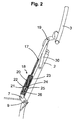
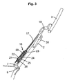
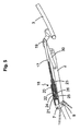
- Fig. 2-5 depicts different positions of the head rest in relation to the back of the chair, in one embodiment of the connecting element according to the present invention, in a length profile.
- Fig. 6 and 7 depicts the connecting element in fig 2-5 in a locked and an uncoupled position, respectively, in larger detail.
- a chair 1 of the type disclosed in WO 92/06621 is mainly shown, which chair 1 comprises an adjustable back of the chair 2 with an adjustable head rest 3.
- the chair specified in fig. 1 has a special adjustment of the head rest 3.
- the head rest is active in that it maintains an upright position when the back of the chair is reclined. In the reclined position of the back of the chair this function of the head rest may be disconnected by pulling the head rest somewhat forward. The head rest may then be reclined.
- a connecting element 18 with a rod 17 is also shown, which is attached at the top to a joint 19 on the head rest, and which in the lower part is attached to a joint 7 on a permanent part of the framework of the chair, in a distance from the axis of rotation 9.
- the connecting element 18 with the rod 17 may take mainly two different length positions and has its shortest length amongst others when the back of the chair 2 is in an upright position, wherein the head rest 3 is almost an extension of the back of the chair 2, and forms its largest angle (almost 180°) with the back of the chair. When the back of the chair 2 is reclined to the position shown in fig.
- the connecting element 18 comprises groove 21, blocking device 22 and coupling organ 24 which cooperate with each other so that the head rest 3 may be affected in the above mentioned ways by changing the length of the connecting element.
- the length of the connecting element 18 is further restricted in this embodiment by the stopping device 25 and track 26.
- the connecting element 18 comprises a guide 20 in the form of a circular cylinder, a blocking device 22 in the form of a sphere, a slider 23 and a stopping device 25.
- the coupling organ 24 is in the form of a first track in slider 23, wherein the coupling organ 24 has a more shallow part A and a deeper part B, which cooperate with the blocking device 22 and a groove 21 in guide 20.
- the connecting element may comprise a track 26 in slider 23 with end restrictions C and D which cooperate with a stopping device 25 placed in a hole in guide 20.
- the stopping device 25 is held in place in guide 20 by a spring ring 27 surrounding the guide 20.
- the main parts of the connecting element such as the guide 20, the slider 23, and the rod 17 may be produced in a mouldable material such as a plastic material.
- the blocking device 22 In an upright position of the back of the chair 2, the blocking device 22 will fall down between the shallow position A in the coupling organ 24 in the slider 23 and the groove 21 in the guide 20, due to gravity as is evident from fig. 2.
- the head rest function is locked.
- a small (manual) pull forwards of the head rest 3 will release the blocking device 22 out of clamp between the shallow position A in the coupling organ 24 and the groove 21, down into the deeper position B of the coupling organ 24 due to gravity, and thereby uncouple the head rest as shown in fig. 5.
- the movement of the head rest 3 is further restricted in this embodiment by the movement of the slider 23 in guide 20 being restricted by the guiders stopping device 25, which run in the gliders track 26 between the end restrictions C and D.
- the movement both forward and backwards is restricted, where the latter is of most current interest in that the slider 23 moves in the direction out of the guide 20 until the stopping device 25 stands against end restriction D in then track 26, see fig. 5 and 7.
- the chair is further equipped with a driver 30 attached to the back of the chair in its one end and to the joint 19 on the head rest in its other end by a track 31, as shown in fig. 4.
- the driver 30 secures the head rest 3 against backward distortion in the reclined position, and brings the head rest 3 with it when the back of the chair 2 is raised up such that the slider 23 moves all the way down into the guide 20 in the upright position, making the blocking device 22 fall down between the groove 21 and position A in the coupling organ 24 again.
- the stopping device with track as described over may be arranged on other places in the connecting element than shown in the figures, or on other movable parts between the back of the chair 2 and the head rest 3, such as for example on the arched guides of the head rest or as separate stopping devices similar to the driver 30, or the function may be attended by the upholstery.
- the driver 30 may likewise be arranged on other places between the back of the chair 2 and the head rest 3, or its function may be attended by the upholstery for example, or devices in the arched guides of the head rest. Further, the driver 30 may be constructed in other ways such as a wire or a similar flexible organ with a certain length.
- the connecting element may in its upper end be formed as a rod 17, which is fastened in the joint 19 on the head rest.
- the rod part may have a shape which gives a suitable elastic flexibility.
- the rod may be somewhat arched or contain at least one slight angle.
- the rod 17 may be attached to the slider 23 in a way that allows rotation and/or variation of the angle between them.
- the guide 20 with slider may have another cross section than circular, such as for example oval or square.
- the blocking device 22 may be a roll or another element influenced by gravity.
- the coupling organ 24 and the groove 21 may have another suitable design adapted to the blocking device 22, such as a simple v-formed track which secures the above mentioned function of the groove 21, blocking device 22 and coupling organ 24.
Abstract
Description
- The present invention relates to a length-adjustable connecting element for a chair, with adjustable back of the chair and head rest, arranged between the head rest and the chair construction, which by movement of the adjustable back of the chair is arranged to affect the angle of the head rest in relation to the back of the chair, as the angle of the head rest may be altered by changing the effective length of the connecting element in the reclined position of the back of the chair.
- From WO 92/06621, a device for a chair with adjustable back of the chair and head rest is known, wherein the head rest may be adjusted in relation to the relative reclining positions of the back of the chair, using a telescopic length adjustable connecting element that stretches between the head rest and a suitable location on the chair. This device has relative complicated and expensive regulating organs and locking organs which must be operated through the upholstery of the chair, and they are difficult to make functioning in a satisfactory way.
- The basis of the present invention lies in the object of presenting a connecting element that comprises simple parts, that is robust and dependable and that is silent in use.
- An additional object of the present invention is to provide a connecting element with manual or automatic adjustment that may be adapted to any chair with a head rest, including such chairs having arched guides, and also such chairs with adjustable lower back support.
- The aforementioned objects are achieved by a device of the introductory given kind, which according to the invention is characterised by the features evident from the enclosed
patent claim 1. - Additional features and advantages of the present invention will be apparent from the following description taken in association with the enclosed drawings, and the additional enclosed patent claims.
- Fig. 1 is a phantom drawing of a chair according to the invention seen from the side, wherein the back of the chair is in a reclined position, simultaneously as the head rest is shown in a reclined position in dotted line.
- Fig. 2-5 depicts different positions of the head rest in relation to the back of the chair, in one embodiment of the connecting element according to the present invention, in a length profile.
- Fig. 6 and 7 depicts the connecting element in fig 2-5 in a locked and an uncoupled position, respectively, in larger detail.
- On fig. 1 the framework of a
chair 1 of the type disclosed in WO 92/06621 is mainly shown, whichchair 1 comprises an adjustable back of thechair 2 with anadjustable head rest 3. - It should be understood that the chair specified in fig. 1 has a special adjustment of the
head rest 3. The head rest is active in that it maintains an upright position when the back of the chair is reclined. In the reclined position of the back of the chair this function of the head rest may be disconnected by pulling the head rest somewhat forward. The head rest may then be reclined. - In fig. 1 the back of the
chair 2 is supported about an axis ofrotation 9 making it possible for the back of thechair 2 to take different angular positions, as the back of the chair in the lower part at the same time has aconnection joint 10 to thechair seat 5, which is accomplish by aknown movement mechanism 8. - In fig. 1 a connecting
element 18 with arod 17 is also shown, which is attached at the top to ajoint 19 on the head rest, and which in the lower part is attached to ajoint 7 on a permanent part of the framework of the chair, in a distance from the axis ofrotation 9. The connectingelement 18 with therod 17 may take mainly two different length positions and has its shortest length amongst others when the back of thechair 2 is in an upright position, wherein thehead rest 3 is almost an extension of the back of thechair 2, and forms its largest angle (almost 180°) with the back of the chair. When the back of thechair 2 is reclined to the position shown in fig. 1, the relative movement of the back of thechair 2, and the connectingelement 18 with therod 17, will imply that thehead rest 3 is pulled forward to a steeper angle in relation to the back of thechair 2. With the help of a mechanism, the connecting element may then be lengthened, so that the head rest may be reclined to the dotted position 3'. - In fig. 2-5 one embodiment for a connecting element according to the present invention is shown.
- In this embodiment the connecting
element 18 comprisesgroove 21,blocking device 22 andcoupling organ 24 which cooperate with each other so that thehead rest 3 may be affected in the above mentioned ways by changing the length of the connecting element. The length of the connectingelement 18 is further restricted in this embodiment by thestopping device 25 andtrack 26. - In fig. 6 and 7 it is shown in greater detail that the connecting
element 18 comprises aguide 20 in the form of a circular cylinder, ablocking device 22 in the form of a sphere, aslider 23 and astopping device 25. Thecoupling organ 24 is in the form of a first track inslider 23, wherein thecoupling organ 24 has a more shallow part A and a deeper part B, which cooperate with theblocking device 22 and agroove 21 inguide 20. - Likewise, it may from fig. 6 and 7 be seen that the connecting element may comprise a
track 26 inslider 23 with end restrictions C and D which cooperate with astopping device 25 placed in a hole inguide 20. Thestopping device 25 is held in place inguide 20 by aspring ring 27 surrounding theguide 20. - The main parts of the connecting element, such as the
guide 20, theslider 23, and therod 17 may be produced in a mouldable material such as a plastic material. - In an upright position of the back of the
chair 2, theblocking device 22 will fall down between the shallow position A in thecoupling organ 24 in theslider 23 and thegroove 21 in theguide 20, due to gravity as is evident from fig. 2. When the back of thechair 2 is reclined as shown in fig. 3, the head rest function is locked. In the reclined position of the back of thechair 2 as shown in 4, a small (manual) pull forwards of thehead rest 3 will release theblocking device 22 out of clamp between the shallow position A in thecoupling organ 24 and thegroove 21, down into the deeper position B of thecoupling organ 24 due to gravity, and thereby uncouple the head rest as shown in fig. 5. This implies that theslider 23 will move in theguide 20, and not fall down between position A in the coupling organ and thegroove 21 until in a new upright position of the back of thechair 2. When the back of thechair 2 is reclined down again, theblocking device 22 will lock theslider 23 to theguide 20 and the head rest function is regained in cooperation with the connectingelement 18. - The movement of the
head rest 3 is further restricted in this embodiment by the movement of theslider 23 inguide 20 being restricted by theguiders stopping device 25, which run in thegliders track 26 between the end restrictions C and D. This restricts the movement of the head rest forward, in upright position, as theslider 23 may not be moved further into theguide 20 than when thestopping device 25 stands against the end restriction C intrack 26, see fig 1 and fig 6. In the reclined position ofhead rest 3, the movement both forward and backwards is restricted, where the latter is of most current interest in that theslider 23 moves in the direction out of theguide 20 until thestopping device 25 stands against end restriction D in then track 26, see fig. 5 and 7. - In the embodiment shown in fig. 2-5 the chair is further equipped with a
driver 30 attached to the back of the chair in its one end and to thejoint 19 on the head rest in its other end by atrack 31, as shown in fig. 4. Thedriver 30 secures thehead rest 3 against backward distortion in the reclined position, and brings thehead rest 3 with it when the back of thechair 2 is raised up such that theslider 23 moves all the way down into theguide 20 in the upright position, making theblocking device 22 fall down between thegroove 21 and position A in thecoupling organ 24 again. - In other embodiments the stopping device with track as described over may be arranged on other places in the connecting element than shown in the figures, or on other movable parts between the back of the
chair 2 and thehead rest 3, such as for example on the arched guides of the head rest or as separate stopping devices similar to thedriver 30, or the function may be attended by the upholstery. - The
driver 30 may likewise be arranged on other places between the back of thechair 2 and thehead rest 3, or its function may be attended by the upholstery for example, or devices in the arched guides of the head rest. Further, thedriver 30 may be constructed in other ways such as a wire or a similar flexible organ with a certain length. - The connecting element may in its upper end be formed as a
rod 17, which is fastened in thejoint 19 on the head rest. The rod part may have a shape which gives a suitable elastic flexibility. Alternatively the rod may be somewhat arched or contain at least one slight angle. Further, therod 17 may be attached to theslider 23 in a way that allows rotation and/or variation of the angle between them. - A person skilled in the art will understand that the embodiment over is only one example, and that the invention is restricted only by the claims enclosed. The
guide 20 with slider may have another cross section than circular, such as for example oval or square. Likewise theblocking device 22 may be a roll or another element influenced by gravity. Thecoupling organ 24 and thegroove 21 may have another suitable design adapted to theblocking device 22, such as a simple v-formed track which secures the above mentioned function of thegroove 21,blocking device 22 andcoupling organ 24. - Even if it is preferable both in technical production and in costs to produce most of the parts of the connecting element according to the invention from a mouldable plastic material, it will be understood that other materials such as metal or sintered materials may be used.
Claims (10)
- Connecting element (18) for a chair (1) with an adjustable back (2) and head rest (3), said connecting element being positioned between a section on the head rest (3) and an attachment section on the chair, which by movement of the adjustable back of the chair (2) is arranged to affect the angle of the head rest (3) in relation to the back of the chair (2), wherein the angle of the head rest in the reclined position of the back of the chair (2) may be changed by altering the effective length of the connecting element, wherein the connecting element (18) comprises a guide (20) that receives a slider (23) that may be locked in relation to each other, characterised in that the guide (20) and the slider (23) cooperate with a gravity influenced blocking device (22), to cause a locked connecting position for the connecting element (18) in a shortened state of the connecting element.
- Connecting element according to claim 1,
characterised in that the connecting element (18) is accomplished with a stopping device (25) that limits the outer movement of the slider (23) in the guide (20). - Connecting element according to claim 2,
characterised in that the stopping device (25) consists of a stopper attached to the guide (20) that runs in a track (26) in the slider (23), which track limits the movement of the slider (23) in the guide (20) to a first end restriction (C) and likewise hinders that the slider (23) is pulled out of the guide (20) by a second end restriction (D). - Connecting element according to claims 1-3,
characterised in that the guide (20) of the connecting element (18) and/or slider (23) and/or rod (17) is made of a mouldable material such as a plastic material. - Connecting element according to the claims 1-4,
characterised in that the connecting element (18) is equipped with a rod (17) that may be partly made of a flexible material and/or is slightly arched or contains at least a slight angle. - Connecting element according to the claims 1-5,
characterised in that the rod (17) is further attached to the slider (23) in a way which allows rotation and/or variation of the angle between them - Connecting element according to the claims 1-6,
characterised in that the connecting element has a cross section which is mainly circular, oval, square or multi-sided, preferably circular. - Connecting element according to the claims 1-7,
characterised in that the blocking device (22) is in the form of a sphere or a cylinder or other movable blocking device, preferably a sphere. - Chair (1) with adjustable back (2) and head rest (3), with a connecting element according to one of the preceding claims, arranged between a section on the head rest (3) and an attachment section on the chair, which by movement of the adjustable back of the chair (2) is arranged to affect the angle of the head rest (3) in relation to the back of the chair (2), wherein the angle of the head rest in the reclined position of the back of the chair (2) may be changed by altering the effective length of the connecting element,
characterised in that the blocking device (22) in an upright position of the back of the chair (2) is locked between a shallow part (A) of a coupling organ (24) in the slider (23) and groove (21) in the guide (20) to perform the head rest function until the back of the chair is totally reclined,- and in that a small (manual) forward pull of the head rest in the reclined position of the back of the chair will release the blocking device (22) from the locked position and fall down in the deeper position (B) of the coupling organ (24) due to gravity, in order to uncouple the head rest (3),- and in that the blocking device (22) first in a new upright position of the back of the chair (2) again will fall down between the shallow part (A) in the coupling organ (24) in the slider (23) and groove (21) in guide (20) in order to regain the function of the head rest in cooperation with the connecting element (18). - Chair according to claim 9,
characterised in that it comprises a driver (30) attached between the head rest (3) and the back of the chair (2) limiting the rotational movement of the head rest, in addition to a connecting element according to any claims 1-9.
Priority Applications (1)
| Application Number | Priority Date | Filing Date | Title |
|---|---|---|---|
| CY20061101549T CY1107655T1 (en) | 2001-07-05 | 2006-10-26 | TWO STAGES CONNECTION |
Applications Claiming Priority (3)
| Application Number | Priority Date | Filing Date | Title |
|---|---|---|---|
| NO20013342A NO313783B1 (en) | 2001-07-05 | 2001-07-05 | Two-stage draw element |
| NO20013342 | 2001-07-05 | ||
| PCT/NO2002/000248 WO2003003879A1 (en) | 2001-07-05 | 2002-07-05 | Two-step connecting element |
Publications (2)
| Publication Number | Publication Date |
|---|---|
| EP1408794A1 EP1408794A1 (en) | 2004-04-21 |
| EP1408794B1 true EP1408794B1 (en) | 2006-09-13 |
Family
ID=19912641
Family Applications (1)
| Application Number | Title | Priority Date | Filing Date |
|---|---|---|---|
| EP02741546A Expired - Lifetime EP1408794B1 (en) | 2001-07-05 | 2002-07-05 | Two-step connecting element |
Country Status (14)
| Country | Link |
|---|---|
| US (2) | US7322641B2 (en) |
| EP (1) | EP1408794B1 (en) |
| JP (1) | JP4276938B2 (en) |
| AT (1) | ATE339132T1 (en) |
| AU (1) | AU2002314645B2 (en) |
| CA (1) | CA2450817C (en) |
| CY (1) | CY1107655T1 (en) |
| DE (1) | DE60214722T2 (en) |
| DK (1) | DK1408794T3 (en) |
| ES (1) | ES2272731T3 (en) |
| HK (1) | HK1060265A1 (en) |
| NO (1) | NO313783B1 (en) |
| PT (1) | PT1408794E (en) |
| WO (1) | WO2003003879A1 (en) |
Cited By (4)
| Publication number | Priority date | Publication date | Assignee | Title |
|---|---|---|---|---|
| WO2008041868A3 (en) * | 2006-10-04 | 2008-07-31 | Formway Furniture Ltd | A chair |
| USD613084S1 (en) | 2008-12-12 | 2010-04-06 | Formway Furniture Limited | Chair |
| USD615784S1 (en) | 2008-04-09 | 2010-05-18 | Formway Furniture Limited | Chair back |
| USD616213S1 (en) | 2008-04-09 | 2010-05-25 | Formway Furniture Limited | Chair |
Families Citing this family (11)
| Publication number | Priority date | Publication date | Assignee | Title |
|---|---|---|---|---|
| NO326574B1 (en) * | 2007-03-13 | 2009-01-12 | Sapdesign As | Device by chair with adjustable angle between chair seat and back |
| WO2008129567A1 (en) * | 2007-04-18 | 2008-10-30 | Stema S.R.L. | Mechanism for reclining armchairs or sofas |
| DE202007009877U1 (en) * | 2007-07-14 | 2007-09-20 | Stanzwerk Wetter Sichelschmidt Gmbh & Co. Kg | seating |
| NO328012B1 (en) | 2007-10-10 | 2009-11-09 | Mobeldesign As | Seating furniture device |
| JP5442239B2 (en) * | 2008-11-19 | 2014-03-12 | 朝日木材加工株式会社 | Reclining seat |
| DE102010049040A1 (en) * | 2010-10-21 | 2012-04-26 | Carsten Seichter | Seat furniture for stretching of frontal body muscles, seat and backrest with variable opening angle between seat and backrest at seating positions and stretching positions |
| CN102228345B (en) * | 2011-03-25 | 2013-06-19 | 谢光 | Multifunctional fitness chair convenient for neck strengthening |
| DE102014118163A1 (en) * | 2014-12-08 | 2016-06-09 | Ferdinand Lusch Gmbh & Co. Kg | Seating furniture with pivoting functional part |
| US9900481B2 (en) * | 2015-11-25 | 2018-02-20 | Semiconductor Components Industries, Llc | Imaging pixels having coupled gate structure |
| FR3052348A1 (en) * | 2016-06-10 | 2017-12-15 | Didier Monard | RECLINING ARMCHAIR |
| US10450072B2 (en) * | 2017-11-28 | 2019-10-22 | B/E Aerospace, Inc. | Seatback articulation assembly and method |
Family Cites Families (18)
| Publication number | Priority date | Publication date | Assignee | Title |
|---|---|---|---|---|
| US2952303A (en) * | 1958-04-15 | 1960-09-13 | Albert M Spound | Manual and automatically projectible headrest |
| US2989341A (en) * | 1958-12-08 | 1961-06-20 | Anton Lorenz | Head-rest and control |
| US3027194A (en) * | 1959-08-03 | 1962-03-27 | Young Spring & Wire Corp | Headrest assembly for vehicle seats |
| US3191990A (en) * | 1962-05-31 | 1965-06-29 | Rugg Donald Edwin | Reclining mechanism for wheelchairs and the like |
| US3572831A (en) * | 1969-04-21 | 1971-03-30 | American Seating Co | Study unit |
| BE760088A (en) * | 1969-12-17 | 1971-05-17 | Giroflex Entwicklungs Ag | Rocking chair |
| US3642088A (en) * | 1970-02-02 | 1972-02-15 | Case Co J I | Self-locating vertically and facingly adjustable seat |
| US4643472A (en) * | 1984-12-24 | 1987-02-17 | Combustion Engineering, Inc. | Rapid installation tube gripper |
| US4693516A (en) * | 1986-08-14 | 1987-09-15 | Knecht Hillery G | Headrest assembly and method for making same |
| DE3636026A1 (en) * | 1986-10-23 | 1988-04-28 | Hilti Ag | HAND DEVICE WITH TOOL HOLDER |
| NO176384C (en) | 1990-10-12 | 1995-03-29 | Ekornes Fabrikker As J E | Device by a chair, especially a chair with adjustable back and headrest |
| US5366313A (en) * | 1992-11-02 | 1994-11-22 | Norco, Inc. | Strut construction |
| IT1291007B1 (en) * | 1997-01-14 | 1998-12-14 | Bruzolo Manifatt Gestind Mb | HEADREST FOR VEHICLE SEATS |
| US5816658A (en) * | 1997-05-23 | 1998-10-06 | Flexsteel Industries, Inc. | Head rest lock |
| DE19727168C2 (en) * | 1997-06-26 | 2000-08-24 | Grammer Ag | Telescopic headrest |
| US5927804A (en) * | 1998-02-11 | 1999-07-27 | Trw Inc. | Vehicle occupant protection apparatus |
| NO991126D0 (en) | 1999-03-08 | 1999-03-08 | Ekornes Asa | Device by a chair, especially a chair with adjustable back and headrest |
| DE10209189A1 (en) * | 2002-03-04 | 2003-09-25 | Daimler Chrysler Ag | Vehicle seat with tilt-adjustable headrest |
-
2001
- 2001-07-05 NO NO20013342A patent/NO313783B1/en not_active IP Right Cessation
-
2002
- 2002-07-05 DE DE60214722T patent/DE60214722T2/en not_active Expired - Lifetime
- 2002-07-05 JP JP2003509898A patent/JP4276938B2/en not_active Expired - Lifetime
- 2002-07-05 DK DK02741546T patent/DK1408794T3/en active
- 2002-07-05 US US10/482,932 patent/US7322641B2/en not_active Expired - Lifetime
- 2002-07-05 EP EP02741546A patent/EP1408794B1/en not_active Expired - Lifetime
- 2002-07-05 PT PT02741546T patent/PT1408794E/en unknown
- 2002-07-05 WO PCT/NO2002/000248 patent/WO2003003879A1/en active IP Right Grant
- 2002-07-05 ES ES02741546T patent/ES2272731T3/en not_active Expired - Lifetime
- 2002-07-05 AT AT02741546T patent/ATE339132T1/en active
- 2002-07-05 AU AU2002314645A patent/AU2002314645B2/en not_active Expired
- 2002-07-05 CA CA2450817A patent/CA2450817C/en not_active Expired - Lifetime
-
2004
- 2004-05-06 HK HK04103208A patent/HK1060265A1/en not_active IP Right Cessation
-
2006
- 2006-10-26 CY CY20061101549T patent/CY1107655T1/en unknown
-
2007
- 2007-08-22 US US11/894,965 patent/US7594693B2/en active Active
Cited By (10)
| Publication number | Priority date | Publication date | Assignee | Title |
|---|---|---|---|---|
| WO2008041868A3 (en) * | 2006-10-04 | 2008-07-31 | Formway Furniture Ltd | A chair |
| US8029060B2 (en) | 2006-10-04 | 2011-10-04 | Formway Furniture Limited | Chair |
| US8087727B2 (en) | 2006-10-04 | 2012-01-03 | Formway Furniture Limited | Chair |
| US8096615B2 (en) | 2006-10-04 | 2012-01-17 | Formay Furniture Limited | Chair |
| US8613481B2 (en) | 2006-10-04 | 2013-12-24 | Formway Furniture Limited | Chair |
| US8668265B2 (en) | 2006-10-04 | 2014-03-11 | Formway Furniture Limited | Chair |
| US8888183B2 (en) | 2006-10-04 | 2014-11-18 | Formway Furniture Limited | Chair |
| USD615784S1 (en) | 2008-04-09 | 2010-05-18 | Formway Furniture Limited | Chair back |
| USD616213S1 (en) | 2008-04-09 | 2010-05-25 | Formway Furniture Limited | Chair |
| USD613084S1 (en) | 2008-12-12 | 2010-04-06 | Formway Furniture Limited | Chair |
Also Published As
| Publication number | Publication date |
|---|---|
| NO20013342D0 (en) | 2001-07-05 |
| US20040239154A1 (en) | 2004-12-02 |
| JP2004530522A (en) | 2004-10-07 |
| DE60214722T2 (en) | 2007-09-13 |
| US7322641B2 (en) | 2008-01-29 |
| JP4276938B2 (en) | 2009-06-10 |
| CA2450817C (en) | 2011-02-01 |
| CY1107655T1 (en) | 2013-04-18 |
| NO20013342A (en) | 2002-12-02 |
| HK1060265A1 (en) | 2004-08-06 |
| EP1408794A1 (en) | 2004-04-21 |
| CA2450817A1 (en) | 2003-01-16 |
| AU2002314645B2 (en) | 2007-07-19 |
| US7594693B2 (en) | 2009-09-29 |
| US20070290529A1 (en) | 2007-12-20 |
| NO313783B1 (en) | 2002-12-02 |
| ES2272731T3 (en) | 2007-05-01 |
| DK1408794T3 (en) | 2007-01-29 |
| DE60214722D1 (en) | 2006-10-26 |
| PT1408794E (en) | 2007-01-31 |
| WO2003003879A1 (en) | 2003-01-16 |
| ATE339132T1 (en) | 2006-10-15 |
Similar Documents
| Publication | Publication Date | Title |
|---|---|---|
| US7594693B2 (en) | Two-step connecting element | |
| AU2002314645A1 (en) | Two-step connecting element | |
| AU648356B2 (en) | Arrangement in a recline chair | |
| US6132001A (en) | Adjustment device for an arm of a chair | |
| WO2006138523A3 (en) | Reversible lounge chair | |
| EP1301107A1 (en) | Ergonomic office chair with an extending foot | |
| US20100033005A1 (en) | Adjustment mechanism for armrest | |
| US6139106A (en) | Headrest for dental use | |
| TWM586565U (en) | Chair armrests | |
| US11259949B2 (en) | Orthopedic device | |
| CN107536317B (en) | Seat reclining mechanism with two springs | |
| EP1616504A2 (en) | Telescopic armrest | |
| WO1984002074A1 (en) | An arrangement for supporting a person | |
| US6176507B1 (en) | Child's push-chair for a telescopic extendable cradle, and the corresponding cradle | |
| CN206615269U (en) | A kind of stroller seat recliner | |
| CN107161201A (en) | A kind of stroller seat recliner | |
| CN219306331U (en) | Position-adjustable suspension deck chair | |
| CN211427833U (en) | Movable LED aeolian bell limiter | |
| WO2000057754A8 (en) | An arrangement in a chair, particularly a chair having an adjustable back and headrest | |
| CN220800554U (en) | Multi-position adjustable seat | |
| CN212685697U (en) | Stepless adjusting mechanism of seat backrest | |
| CN216059890U (en) | Motion adjusting structure of seat and motion seat | |
| KR200227022Y1 (en) | A fishing chair | |
| KR200197808Y1 (en) | Adjustable armrest for chair | |
| KR200316002Y1 (en) | chair for student |
Legal Events
| Date | Code | Title | Description |
|---|---|---|---|
| PUAI | Public reference made under article 153(3) epc to a published international application that has entered the european phase |
Free format text: ORIGINAL CODE: 0009012 |
|
| 17P | Request for examination filed |
Effective date: 20040115 |
|
| AK | Designated contracting states |
Kind code of ref document: A1 Designated state(s): AT BE BG CH CY CZ DE DK EE ES FI FR GB GR IE IT LI LU MC NL PT SE SK TR |
|
| AX | Request for extension of the european patent |
Extension state: AL LT LV MK RO SI |
|
| REG | Reference to a national code |
Ref country code: HK Ref legal event code: DE Ref document number: 1060265 Country of ref document: HK |
|
| GRAP | Despatch of communication of intention to grant a patent |
Free format text: ORIGINAL CODE: EPIDOSNIGR1 |
|
| GRAS | Grant fee paid |
Free format text: ORIGINAL CODE: EPIDOSNIGR3 |
|
| GRAA | (expected) grant |
Free format text: ORIGINAL CODE: 0009210 |
|
| AK | Designated contracting states |
Kind code of ref document: B1 Designated state(s): AT BE BG CH CY CZ DE DK EE ES FI FR GB GR IE IT LI LU MC NL PT SE SK TR |
|
| PG25 | Lapsed in a contracting state [announced via postgrant information from national office to epo] |
Ref country code: IT Free format text: LAPSE BECAUSE OF FAILURE TO SUBMIT A TRANSLATION OF THE DESCRIPTION OR TO PAY THE FEE WITHIN THE PRESCRIBED TIME-LIMIT;WARNING: LAPSES OF ITALIAN PATENTS WITH EFFECTIVE DATE BEFORE 2007 MAY HAVE OCCURRED AT ANY TIME BEFORE 2007. THE CORRECT EFFECTIVE DATE MAY BE DIFFERENT FROM THE ONE RECORDED. Effective date: 20060913 |
|
| REG | Reference to a national code |
Ref country code: GB Ref legal event code: FG4D |
|
| REG | Reference to a national code |
Ref country code: CH Ref legal event code: EP |
|
| REG | Reference to a national code |
Ref country code: IE Ref legal event code: FG4D |
|
| REF | Corresponds to: |
Ref document number: 60214722 Country of ref document: DE Date of ref document: 20061026 Kind code of ref document: P |
|
| REG | Reference to a national code |
Ref country code: HK Ref legal event code: GR Ref document number: 1060265 Country of ref document: HK |
|
| REG | Reference to a national code |
Ref country code: CH Ref legal event code: NV Representative=s name: PATENTANWAELTE SCHAAD, BALASS, MENZL & PARTNER AG |
|
| REG | Reference to a national code |
Ref country code: SE Ref legal event code: TRGR |
|
| REG | Reference to a national code |
Ref country code: GR Ref legal event code: EP Ref document number: 20060404255 Country of ref document: GR |
|
| REG | Reference to a national code |
Ref country code: DK Ref legal event code: T3 |
|
| REG | Reference to a national code |
Ref country code: PT Ref legal event code: SC4A Free format text: AVAILABILITY OF NATIONAL TRANSLATION Effective date: 20061213 |
|
| REG | Reference to a national code |
Ref country code: EE Ref legal event code: FG4A Ref document number: E000722 Country of ref document: EE Effective date: 20061212 |
|
| ET | Fr: translation filed | ||
| REG | Reference to a national code |
Ref country code: ES Ref legal event code: FG2A Ref document number: 2272731 Country of ref document: ES Kind code of ref document: T3 |
|
| PLBE | No opposition filed within time limit |
Free format text: ORIGINAL CODE: 0009261 |
|
| STAA | Information on the status of an ep patent application or granted ep patent |
Free format text: STATUS: NO OPPOSITION FILED WITHIN TIME LIMIT |
|
| 26N | No opposition filed |
Effective date: 20070614 |
|
| REG | Reference to a national code |
Ref country code: EE Ref legal event code: HC1A Ref document number: E000722 Country of ref document: EE |
|
| REG | Reference to a national code |
Ref country code: FR Ref legal event code: PLFP Year of fee payment: 15 |
|
| REG | Reference to a national code |
Ref country code: FR Ref legal event code: PLFP Year of fee payment: 16 |
|
| REG | Reference to a national code |
Ref country code: FR Ref legal event code: PLFP Year of fee payment: 17 |
|
| PGFP | Annual fee paid to national office [announced via postgrant information from national office to epo] |
Ref country code: NL Payment date: 20210630 Year of fee payment: 20 Ref country code: SK Payment date: 20210630 Year of fee payment: 20 Ref country code: PT Payment date: 20210624 Year of fee payment: 20 |
|
| PGFP | Annual fee paid to national office [announced via postgrant information from national office to epo] |
Ref country code: BE Payment date: 20210629 Year of fee payment: 20 Ref country code: SE Payment date: 20210630 Year of fee payment: 20 Ref country code: DK Payment date: 20210630 Year of fee payment: 20 |
|
| PGFP | Annual fee paid to national office [announced via postgrant information from national office to epo] |
Ref country code: AT Payment date: 20210629 Year of fee payment: 20 Ref country code: CZ Payment date: 20210630 Year of fee payment: 20 Ref country code: EE Payment date: 20210712 Year of fee payment: 20 Ref country code: FI Payment date: 20210707 Year of fee payment: 20 Ref country code: CY Payment date: 20210625 Year of fee payment: 20 Ref country code: BG Payment date: 20210630 Year of fee payment: 20 Ref country code: FR Payment date: 20210708 Year of fee payment: 20 Ref country code: MC Payment date: 20210709 Year of fee payment: 20 Ref country code: LU Payment date: 20210726 Year of fee payment: 20 Ref country code: IT Payment date: 20210716 Year of fee payment: 20 Ref country code: IE Payment date: 20210723 Year of fee payment: 20 |
|
| PGFP | Annual fee paid to national office [announced via postgrant information from national office to epo] |
Ref country code: GR Payment date: 20210726 Year of fee payment: 20 Ref country code: TR Payment date: 20210702 Year of fee payment: 20 Ref country code: DE Payment date: 20210727 Year of fee payment: 20 Ref country code: CH Payment date: 20210714 Year of fee payment: 20 Ref country code: GB Payment date: 20210712 Year of fee payment: 20 Ref country code: ES Payment date: 20210802 Year of fee payment: 20 |
|
| REG | Reference to a national code |
Ref country code: DE Ref legal event code: R071 Ref document number: 60214722 Country of ref document: DE |
|
| REG | Reference to a national code |
Ref country code: NL Ref legal event code: MK Effective date: 20220704 |
|
| REG | Reference to a national code |
Ref country code: DK Ref legal event code: EUP Expiry date: 20220705 |
|
| REG | Reference to a national code |
Ref country code: CH Ref legal event code: PL |
|
| REG | Reference to a national code |
Ref country code: SK Ref legal event code: MK4A Ref document number: E 1274 Country of ref document: SK Expiry date: 20220705 Ref country code: GB Ref legal event code: PE20 Expiry date: 20220704 Ref country code: ES Ref legal event code: FD2A Effective date: 20220727 |
|
| PG25 | Lapsed in a contracting state [announced via postgrant information from national office to epo] |
Ref country code: CZ Free format text: LAPSE BECAUSE OF EXPIRATION OF PROTECTION Effective date: 20220705 |
|
| REG | Reference to a national code |
Ref country code: BE Ref legal event code: MK Effective date: 20220705 |
|
| REG | Reference to a national code |
Ref country code: FI Ref legal event code: MAE |
|
| REG | Reference to a national code |
Ref country code: AT Ref legal event code: MK07 Ref document number: 339132 Country of ref document: AT Kind code of ref document: T Effective date: 20220705 |
|
| REG | Reference to a national code |
Ref country code: SE Ref legal event code: EUG |
|
| REG | Reference to a national code |
Ref country code: IE Ref legal event code: MK9A |
|
| PG25 | Lapsed in a contracting state [announced via postgrant information from national office to epo] |
Ref country code: SK Free format text: LAPSE BECAUSE OF EXPIRATION OF PROTECTION Effective date: 20220705 Ref country code: PT Free format text: LAPSE BECAUSE OF EXPIRATION OF PROTECTION Effective date: 20220713 Ref country code: IE Free format text: LAPSE BECAUSE OF EXPIRATION OF PROTECTION Effective date: 20220705 Ref country code: GB Free format text: LAPSE BECAUSE OF EXPIRATION OF PROTECTION Effective date: 20220704 Ref country code: ES Free format text: LAPSE BECAUSE OF EXPIRATION OF PROTECTION Effective date: 20220706 |