EP1409111B1 - Adjustable clamp for securing a filter to an indoor fan - Google Patents
Adjustable clamp for securing a filter to an indoor fan Download PDFInfo
- Publication number
- EP1409111B1 EP1409111B1 EP20010958956 EP01958956A EP1409111B1 EP 1409111 B1 EP1409111 B1 EP 1409111B1 EP 20010958956 EP20010958956 EP 20010958956 EP 01958956 A EP01958956 A EP 01958956A EP 1409111 B1 EP1409111 B1 EP 1409111B1
- Authority
- EP
- European Patent Office
- Prior art keywords
- filter
- fan
- leg
- clamp
- base plate
- Prior art date
- Legal status (The legal status is an assumption and is not a legal conclusion. Google has not performed a legal analysis and makes no representation as to the accuracy of the status listed.)
- Expired - Lifetime
Links
Images
Classifications
-
- B—PERFORMING OPERATIONS; TRANSPORTING
- B01—PHYSICAL OR CHEMICAL PROCESSES OR APPARATUS IN GENERAL
- B01D—SEPARATION
- B01D46/00—Filters or filtering processes specially modified for separating dispersed particles from gases or vapours
- B01D46/10—Particle separators, e.g. dust precipitators, using filter plates, sheets or pads having plane surfaces
-
- B—PERFORMING OPERATIONS; TRANSPORTING
- B01—PHYSICAL OR CHEMICAL PROCESSES OR APPARATUS IN GENERAL
- B01D—SEPARATION
- B01D46/00—Filters or filtering processes specially modified for separating dispersed particles from gases or vapours
- B01D46/0002—Casings; Housings; Frame constructions
- B01D46/0005—Mounting of filtering elements within casings, housings or frames
-
- B—PERFORMING OPERATIONS; TRANSPORTING
- B01—PHYSICAL OR CHEMICAL PROCESSES OR APPARATUS IN GENERAL
- B01D—SEPARATION
- B01D46/00—Filters or filtering processes specially modified for separating dispersed particles from gases or vapours
- B01D46/0027—Filters or filtering processes specially modified for separating dispersed particles from gases or vapours with additional separating or treating functions
- B01D46/0038—Filters or filtering processes specially modified for separating dispersed particles from gases or vapours with additional separating or treating functions with means for influencing the odor, e.g. deodorizing substances
-
- B—PERFORMING OPERATIONS; TRANSPORTING
- B01—PHYSICAL OR CHEMICAL PROCESSES OR APPARATUS IN GENERAL
- B01D—SEPARATION
- B01D53/00—Separation of gases or vapours; Recovering vapours of volatile solvents from gases; Chemical or biological purification of waste gases, e.g. engine exhaust gases, smoke, fumes, flue gases, aerosols
- B01D53/02—Separation of gases or vapours; Recovering vapours of volatile solvents from gases; Chemical or biological purification of waste gases, e.g. engine exhaust gases, smoke, fumes, flue gases, aerosols by adsorption, e.g. preparative gas chromatography
- B01D53/04—Separation of gases or vapours; Recovering vapours of volatile solvents from gases; Chemical or biological purification of waste gases, e.g. engine exhaust gases, smoke, fumes, flue gases, aerosols by adsorption, e.g. preparative gas chromatography with stationary adsorbents
- B01D53/0407—Constructional details of adsorbing systems
- B01D53/0415—Beds in cartridges
-
- F—MECHANICAL ENGINEERING; LIGHTING; HEATING; WEAPONS; BLASTING
- F24—HEATING; RANGES; VENTILATING
- F24F—AIR-CONDITIONING; AIR-HUMIDIFICATION; VENTILATION; USE OF AIR CURRENTS FOR SCREENING
- F24F1/00—Room units for air-conditioning, e.g. separate or self-contained units or units receiving primary air from a central station
- F24F1/0007—Indoor units, e.g. fan coil units
- F24F1/0071—Indoor units, e.g. fan coil units with means for purifying supplied air
-
- B—PERFORMING OPERATIONS; TRANSPORTING
- B01—PHYSICAL OR CHEMICAL PROCESSES OR APPARATUS IN GENERAL
- B01D—SEPARATION
- B01D2253/00—Adsorbents used in seperation treatment of gases and vapours
- B01D2253/10—Inorganic adsorbents
- B01D2253/102—Carbon
-
- B—PERFORMING OPERATIONS; TRANSPORTING
- B01—PHYSICAL OR CHEMICAL PROCESSES OR APPARATUS IN GENERAL
- B01D—SEPARATION
- B01D2257/00—Components to be removed
- B01D2257/90—Odorous compounds not provided for in groups B01D2257/00 - B01D2257/708
-
- B—PERFORMING OPERATIONS; TRANSPORTING
- B01—PHYSICAL OR CHEMICAL PROCESSES OR APPARATUS IN GENERAL
- B01D—SEPARATION
- B01D2259/00—Type of treatment
- B01D2259/45—Gas separation or purification devices adapted for specific applications
- B01D2259/4508—Gas separation or purification devices adapted for specific applications for cleaning air in buildings
-
- B—PERFORMING OPERATIONS; TRANSPORTING
- B01—PHYSICAL OR CHEMICAL PROCESSES OR APPARATUS IN GENERAL
- B01D—SEPARATION
- B01D2259/00—Type of treatment
- B01D2259/45—Gas separation or purification devices adapted for specific applications
- B01D2259/455—Gas separation or purification devices adapted for specific applications for transportable use
-
- B—PERFORMING OPERATIONS; TRANSPORTING
- B01—PHYSICAL OR CHEMICAL PROCESSES OR APPARATUS IN GENERAL
- B01D—SEPARATION
- B01D2273/00—Operation of filters specially adapted for separating dispersed particles from gases or vapours
- B01D2273/30—Means for generating a circulation of a fluid in a filtration system, e.g. using a pump or a fan
-
- F—MECHANICAL ENGINEERING; LIGHTING; HEATING; WEAPONS; BLASTING
- F24—HEATING; RANGES; VENTILATING
- F24F—AIR-CONDITIONING; AIR-HUMIDIFICATION; VENTILATION; USE OF AIR CURRENTS FOR SCREENING
- F24F8/00—Treatment, e.g. purification, of air supplied to human living or working spaces otherwise than by heating, cooling, humidifying or drying
- F24F8/50—Treatment, e.g. purification, of air supplied to human living or working spaces otherwise than by heating, cooling, humidifying or drying by odorisation
-
- Y—GENERAL TAGGING OF NEW TECHNOLOGICAL DEVELOPMENTS; GENERAL TAGGING OF CROSS-SECTIONAL TECHNOLOGIES SPANNING OVER SEVERAL SECTIONS OF THE IPC; TECHNICAL SUBJECTS COVERED BY FORMER USPC CROSS-REFERENCE ART COLLECTIONS [XRACs] AND DIGESTS
- Y10—TECHNICAL SUBJECTS COVERED BY FORMER USPC
- Y10T—TECHNICAL SUBJECTS COVERED BY FORMER US CLASSIFICATION
- Y10T24/00—Buckles, buttons, clasps, etc.
- Y10T24/44—Clasp, clip, support-clamp, or required component thereof
- Y10T24/44017—Clasp, clip, support-clamp, or required component thereof with specific mounting means for attaching to rigid or semirigid supporting structure or structure-to-be-secured
-
- Y—GENERAL TAGGING OF NEW TECHNOLOGICAL DEVELOPMENTS; GENERAL TAGGING OF CROSS-SECTIONAL TECHNOLOGIES SPANNING OVER SEVERAL SECTIONS OF THE IPC; TECHNICAL SUBJECTS COVERED BY FORMER USPC CROSS-REFERENCE ART COLLECTIONS [XRACs] AND DIGESTS
- Y10—TECHNICAL SUBJECTS COVERED BY FORMER USPC
- Y10T—TECHNICAL SUBJECTS COVERED BY FORMER US CLASSIFICATION
- Y10T24/00—Buckles, buttons, clasps, etc.
- Y10T24/44—Clasp, clip, support-clamp, or required component thereof
- Y10T24/44573—Clasp, clip, support-clamp, or required component thereof including track or way guided and retained gripping member
-
- Y—GENERAL TAGGING OF NEW TECHNOLOGICAL DEVELOPMENTS; GENERAL TAGGING OF CROSS-SECTIONAL TECHNOLOGIES SPANNING OVER SEVERAL SECTIONS OF THE IPC; TECHNICAL SUBJECTS COVERED BY FORMER USPC CROSS-REFERENCE ART COLLECTIONS [XRACs] AND DIGESTS
- Y10—TECHNICAL SUBJECTS COVERED BY FORMER USPC
- Y10T—TECHNICAL SUBJECTS COVERED BY FORMER US CLASSIFICATION
- Y10T292/00—Closure fasteners
- Y10T292/37—Portable securer plate or bar
- Y10T292/379—Sliding holding member
Definitions
- the present invention relates generally to fan filters. More specifically, the invention is the addition of an adjustable clamp for securing a filter to a square or round indoor fan.
- U.S. Patent No. 4,781,526 issued on November 1, 1988, for Clarence Mead describes a fan-filter combination comprising a filter affixed to the rear of a fan unit by a parallel bracketing structure (screwed on) into which the filter is slidingly receivable from either above or below because the parallel brackets are several inches short of the top and bottom of the fan unit.
- the 20 inch square furnace filter has two perforated metal sheets and a cardboard frame supporting the filter sheet.
- a first embodiment consists of two parallel U-shaped brackets.
- a second embodiment consists of integrating the grille and brackets.
- a third embodiment consists of a separate metal frame with leg portions integrated with the fan unit by screws.
- the fan-filter combination is distinguishable for relying on its limited bracket coverage and the use of filters with double metal sheets.
- U.S. Patent No. 6,045,329 issued on April 4, 2000, for Randy Sobala describes a fan filter for the rear and sides of a circular or square fan comprising a stretchable polypropylene fabric having two central openings for attachment by hook and loop fastening.
- the fan filter is distinguishable for lacking a rigid frame.
- U.S. Patent No. 6,030,427 issued on February 29, 2000, for James Sorice et al. describes a replaceable air filter apparatus comprising a frame for affixing the apparatus to a house duct work associated with the heating and/or air conditioning system.
- a register is hinged to insert the filter.
- the air filter apparatus is distinguishable for being limited to a house duct work and requiring a hinged register.
- U.S. Patent No. 5,690,719 issued on November 25, 1997, for Joseph Hodge describes a filter apparatus for a forced air system duct containing a self-charging electrostatic filter layer and a second activated charcoal filter layer behind a grill.
- the filters are made of woven polypropylene material.
- the wall mount has a supporting frame and a securing lock. The filter apparatus is distinguishable for being located remotely from the fan.
- U.S. Patent No. 5,573,563 issued on November 12, 1996, for Horace L. Odom et al. describes a micro-rotary screener apparatus comprising a multi-blade rotating air lock within a cylindrical shell having two screens attached directly to the odd numbered blades.
- the first screen is fine mesh stainless steel.
- the second screen has a larger mesh size. The particles from the screens are collected in a bin adjacent the screens.
- the apparatus is distinguishable for requiring two stainless steel mesh screens and a collection box.
- U.S. Patent No. 5,525,145 issued on June 11, 1996, for Joseph Hodge describes a filtering apparatus for a forced air duct grill comprising a self charging electrostatic filter magnetically attachable directly in front of a grill at an end of a cold air return or supply of a forced air system.
- Two open work plates which can be decorated are positioned on either side of the filter.
- the filtering apparatus is distinguishable for requiring the two open work plates and an electrostatic filter.
- U.S. Design Patent No. 420,117 issued on February 1, 2000, for Steven S. Gieseke et al. describes a circular ornamental coalescer filter having an off-center circular grille mounted on a rear plate having a top brace and a pair of canted feet. The device is distinguishable for its asymmetrical filter.
- U.S. Patent No. 5,904,744 issued on May 18, 1999, for Anton Kagan describes a peripheral fan filter for reducing vibration of round fans such as ceiling fans, diffusers and other conventional round fans.
- the filter has four hook and loop fastening regions around the periphery with three of them involving a hook-threaded sheet and pawl teeth.
- the fan filter is distinguishable for its peripheral attachment with various elements.
- U.S. Patent No. 5,868,189 issued on February 9, 1999, for Robin A. Jarvis describes a protective storage cover for a portable circular electric fan.
- the cover for the grille has snaps or two-way zippers for attachment and removal.
- the cover is distinguishable for its storage feature and fasteners.
- United States Patent No. 2,532,162 describes a device for supporting an object such as a mirror, a picture, or the like.
- the present invention relates to an adjustable clamp as claimed in claim 1.
- the adjustable clamp has a substantially flat base plate having a front face and a rear face.
- a boss projects from the rear face of the base plate.
- the boss defines a slot.
- a clamp arm is included having an elongated first leg and a second leg.
- the first leg is slidably inserted into and frictionally engages the slot defined by the boss.
- the second leg has a clamp plate attached thereto.
- the arm has a right angle bend defined between the first leg and the second leg.
- An adhesive coating is disposed on the front face of the base plate, whereby the base plate may be adhesively secured to a support with the clamp plate clamping an article to the support.
- the clamp is adjustable to the article's width by moving the position of the clamp arm in the slot.
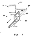
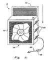
- FIGS. 1 and 2 illustrate an embodiment 54 of a filter attachment system, wherein a plurality of stick-on brackets 56 are applied to each side of a box fan 14, e.g., six, are used to hold the add-on filters 12, and a programmable timer control device 58 is attached to the fan's electric cord 32.
- the unique feature of the stick-on brackets 56 is the flexible adjustment of the extension of the bracket 56 by having an adjustable position clamp arm 60 with a series of shallow notches 62 which is slidable through and frictionally engages a boss 64 projecting from the rear face of a substantially flat, square base plate 63.
- the boss 64 is formed by four spaced apart, triangular wedge plates extending radially towards the corners of the base plate 63 with a small square plate joining the upper vertices of the triangular plates at the four corners of the small square plate.
- the arm 60 has a right-angled bend 68 and ends in a square pad portion 70.
- the base plate 63 has an adhesive coating, double-sided adhesive pad 66, or other means for adhesion to the fan 14 disposed on the front face of the base plate 63.
- the stick-on brackets 56 are preferably made from a thermoplastic material. In use, the base plate 63 of a plurality of brackets are adhered to the size of the fan 14, a filter is placed between the pad portion 70 and the fan 14, and the arms 60 are moved inward to clamp the filter 12 against the fan.
- the programmable timer control device 5B can be a 24 hour and 7 day time clock device for activating and deactivating the fan 14 at preselected times.
- the programmable timer 58 can be inserted inline with the cord 32 as shown, or may be built into the housing of the fan 14.
Abstract
Description
- The present invention relates generally to fan filters. More specifically, the invention is the addition of an adjustable clamp for securing a filter to a square or round indoor fan.
- The related art of interest describes various fan filters, but none discloses the present invention. There is a need for an effective and economical fan filter for especially square-framed fans which can be readily held to the frame by stick-on brackets or clips. The related art will be discussed in the order of perceived relevance to the present invention.
- U.S. Patent No. 4,781,526 issued on November 1, 1988, for Clarence Mead describes a fan-filter combination comprising a filter affixed to the rear of a fan unit by a parallel bracketing structure (screwed on) into which the filter is slidingly receivable from either above or below because the parallel brackets are several inches short of the top and bottom of the fan unit. The 20 inch square furnace filter has two perforated metal sheets and a cardboard frame supporting the filter sheet. A first embodiment consists of two parallel U-shaped brackets. A second embodiment consists of integrating the grille and brackets. A third embodiment consists of a separate metal frame with leg portions integrated with the fan unit by screws. The fan-filter combination is distinguishable for relying on its limited bracket coverage and the use of filters with double metal sheets.
- U.S. Patent No. 6,045,329 issued on April 4, 2000, for Randy Sobala describes a fan filter for the rear and sides of a circular or square fan comprising a stretchable polypropylene fabric having two central openings for attachment by hook and loop fastening. The fan filter is distinguishable for lacking a rigid frame.
- U.S. Patent No. 6,030,427 issued on February 29, 2000, for James Sorice et al. describes a replaceable air filter apparatus comprising a frame for affixing the apparatus to a house duct work associated with the heating and/or air conditioning system. A register is hinged to insert the filter. The air filter apparatus is distinguishable for being limited to a house duct work and requiring a hinged register.
- P.C.T. Patent Application No. WO 00/00775 published on January 6, 2000, for Toshio Tanaka et al. describes a local cleaning type air cleaner comprising a wall installed circular fan having an air filter. The air cleaner device is distinguishable for requiring a grill in front of the filter inlaid in a casing.
- U.S. Patent No. 5,690,719 issued on November 25, 1997, for Joseph Hodge describes a filter apparatus for a forced air system duct containing a self-charging electrostatic filter layer and a second activated charcoal filter layer behind a grill. The filters are made of woven polypropylene material. The wall mount has a supporting frame and a securing lock. The filter apparatus is distinguishable for being located remotely from the fan.
- U.S. Patent No. 5,573,563 issued on November 12, 1996, for Horace L. Odom et al. describes a micro-rotary screener apparatus comprising a multi-blade rotating air lock within a cylindrical shell having two screens attached directly to the odd numbered blades. The first screen is fine mesh stainless steel. The second screen has a larger mesh size. The particles from the screens are collected in a bin adjacent the screens. The apparatus is distinguishable for requiring two stainless steel mesh screens and a collection box.
- U.S. Patent No. 5,525,145 issued on June 11, 1996, for Joseph Hodge describes a filtering apparatus for a forced air duct grill comprising a self charging electrostatic filter magnetically attachable directly in front of a grill at an end of a cold air return or supply of a forced air system. Two open work plates which can be decorated are positioned on either side of the filter. The filtering apparatus is distinguishable for requiring the two open work plates and an electrostatic filter.
- U.S. Patent No. 5,529,593 issued on June 25, 1996, for Jesse K. Simmons describes a filter screen assembly for use with an air intake unit comprising a flexible screen provided as a roll wound onto a spindle. The filter screen assembly is distinguishable for its wound roll feature.
- U.S. Patent No. 4,477,272 issued on October 16, 1984, for Craig E. Hollis et al. describes a soft and pliable circular fan filter mounted on the rear side of the cage of a household fan by two sets of drawstrings. The fan filter is distinguishable for its attachment to the fan by drawstrings.
- U.S. Design Patent No. 420,117 issued on February 1, 2000, for Steven S. Gieseke et al. describes a circular ornamental coalescer filter having an off-center circular grille mounted on a rear plate having a top brace and a pair of canted feet. The device is distinguishable for its asymmetrical filter.
- U.S. Design Patent No. 408,513 issued on April 20, 1999, for Dwayne E. Reede describes a filter with a central aperture for a round fan attachable to the front of the fan with a fold over element. The filter is distinguishable for wrapping around the front of a round fan.
- U.S. Patent No. 5,904,744 issued on May 18, 1999, for Anton Kagan describes a peripheral fan filter for reducing vibration of round fans such as ceiling fans, diffusers and other conventional round fans. The filter has four hook and loop fastening regions around the periphery with three of them involving a hook-threaded sheet and pawl teeth. The fan filter is distinguishable for its peripheral attachment with various elements.
- U.S. Patent No. 5,868,189 issued on February 9, 1999, for Robin A. Jarvis describes a protective storage cover for a portable circular electric fan. The cover for the grille has snaps or two-way zippers for attachment and removal. The cover is distinguishable for its storage feature and fasteners.
- P.C.T. Patent Application No. WO 97/10479 published on March 20, 1997, for David A. West describes a fan air filter screen for a circular fan having a filter guard shaped as a split doughnut with openings in front and the rear and tied together on the fan guard. The device is distinguishable for its split doughnut structure.
- United States Patent No. 2,532,162 describes a device for supporting an object such as a mirror, a picture, or the like.
- None of the above inventions and patents, taken either singly or in combination, is seen to describe the instant invention as claimed.
- The present invention relates to an adjustable clamp as claimed in
claim 1. The adjustable clamp has a substantially flat base plate having a front face and a rear face. A boss projects from the rear face of the base plate. The boss defines a slot. A clamp arm is included having an elongated first leg and a second leg. The first leg is slidably inserted into and frictionally engages the slot defined by the boss. The second leg has a clamp plate attached thereto. The arm has a right angle bend defined between the first leg and the second leg. An adhesive coating is disposed on the front face of the base plate, whereby the base plate may be adhesively secured to a support with the clamp plate clamping an article to the support. The clamp is adjustable to the article's width by moving the position of the clamp arm in the slot. -
- FIG. 1 is a perspective view of a stick-on bracket with an adjustable filter thickness feature for holding filters of different thicknesses onto the fan.
- FIG. 2 is an environmental perspective view of a fan having a filter held by the stick-on brackets and a timer control installed in the fan's electric cord.
- Similar reference characters denote corresponding features consistently throughout the attached drawings.
- FIGS. 1 and 2 illustrate an
embodiment 54 of a filter attachment system, wherein a plurality of stick-onbrackets 56 are applied to each side of abox fan 14, e.g., six, are used to hold the add-onfilters 12, and a programmabletimer control device 58 is attached to the fan'selectric cord 32. The unique feature of the stick-onbrackets 56 is the flexible adjustment of the extension of thebracket 56 by having an adjustableposition clamp arm 60 with a series ofshallow notches 62 which is slidable through and frictionally engages aboss 64 projecting from the rear face of a substantially flat,square base plate 63. Theboss 64 is formed by four spaced apart, triangular wedge plates extending radially towards the corners of thebase plate 63 with a small square plate joining the upper vertices of the triangular plates at the four corners of the small square plate. Thearm 60 has a right-angled bend 68 and ends in asquare pad portion 70. Thebase plate 63 has an adhesive coating, double-sided adhesive pad 66, or other means for adhesion to thefan 14 disposed on the front face of thebase plate 63. The stick-onbrackets 56 are preferably made from a thermoplastic material. In use, thebase plate 63 of a plurality of brackets are adhered to the size of thefan 14, a filter is placed between thepad portion 70 and thefan 14, and thearms 60 are moved inward to clamp thefilter 12 against the fan. - If the
fan 14 has clearance under itsbottom surface 74 due to pads or feet, several more stick-onbrackets 56 can be added at thebottom surface 74 for better securement of thefilter 12. If asecond filter 12 is to be attached to the front of thefan 14,similar brackets 56 can be utilized. The programmable timer control device 5B can be a 24 hour and 7 day time clock device for activating and deactivating thefan 14 at preselected times. Theprogrammable timer 58 can be inserted inline with thecord 32 as shown, or may be built into the housing of thefan 14. - It is to be understood that the present invention is not limited to the embodiments described above, but encompasses any and all embodiments within the scope of the following claims.
Claims (2)
- An adjustable clamp, for securing a filter to a square or round indoor fan, said clamp comprising:a substantially flat base plate having a front face and a rear face; a boss projecting from the rear face of said base plate, the boss defining a slot;a clamp arm having an elongated first leg and a second leg, the first leg being slidably inserted into and frictionally engaging the slot defined by said boss, the arm having a right angle bend defined between the first leg and the second leg;a damp plate attached to said second leg such that the clamp plate extends from the second leg in the longitudinal direction thereof; andan adhesive coating disposed on the front face of said base plate;whereby said base plate may be adhesively secured to a housing for a fan with the clamp plate damping a filter to the housing, the damp being adjustable to the filter width by moving the position of the clamp arm in the slot.
- The adjustable clamp according to claim 1, wherein the first leg of said clamp arm has a plurality of grooves defined therein for locking the position of said clamp arm in said base plate.
Applications Claiming Priority (5)
| Application Number | Priority Date | Filing Date | Title |
|---|---|---|---|
| US903626 | 1997-07-31 | ||
| US21882600P | 2000-07-18 | 2000-07-18 | |
| US218826P | 2000-07-18 | ||
| US09/903,626 US6527838B2 (en) | 2000-07-18 | 2001-07-13 | Indoor fan filter |
| PCT/US2001/022305 WO2002005929A1 (en) | 2000-07-18 | 2001-07-17 | Indoor fan filter |
Publications (3)
| Publication Number | Publication Date |
|---|---|
| EP1409111A1 EP1409111A1 (en) | 2004-04-21 |
| EP1409111A4 EP1409111A4 (en) | 2004-09-22 |
| EP1409111B1 true EP1409111B1 (en) | 2006-07-12 |
Family
ID=26913276
Family Applications (1)
| Application Number | Title | Priority Date | Filing Date |
|---|---|---|---|
| EP20010958956 Expired - Lifetime EP1409111B1 (en) | 2000-07-18 | 2001-07-17 | Adjustable clamp for securing a filter to an indoor fan |
Country Status (7)
| Country | Link |
|---|---|
| US (3) | US6527838B2 (en) |
| EP (1) | EP1409111B1 (en) |
| AT (1) | ATE332735T1 (en) |
| AU (1) | AU2001280561A1 (en) |
| CA (1) | CA2434618A1 (en) |
| DE (1) | DE60121481D1 (en) |
| WO (1) | WO2002005929A1 (en) |
Families Citing this family (46)
| Publication number | Priority date | Publication date | Assignee | Title |
|---|---|---|---|---|
| US6425932B1 (en) * | 1999-07-07 | 2002-07-30 | The Holmes Group, Inc. | Air purifier |
| US6527838B2 (en) * | 2000-07-18 | 2003-03-04 | Giovanni D. Volo | Indoor fan filter |
| US7431901B2 (en) * | 2001-02-02 | 2008-10-07 | The Procter & Gamble Company | Apparatus and method for deodorizing confined air spaces which utilize baking soda |
| US20030188520A1 (en) * | 2002-04-05 | 2003-10-09 | Paul Boulva | Air filter system for a free-standing air blowing fan |
| US7074250B1 (en) * | 2002-09-25 | 2006-07-11 | Black & Decker Inc. | Air filtration unit |
| US20040159239A1 (en) * | 2003-02-14 | 2004-08-19 | Nagem Daniel A. | Multi-phase HVAC filtration system |
| US7614113B2 (en) * | 2003-07-31 | 2009-11-10 | Panasonic Corporation Of North America | Motor enclosure for a vacuum cleaner |
| DE20314492U1 (en) * | 2003-09-17 | 2003-12-11 | Rother, Werner | Fan with filter device |
| US7150778B1 (en) | 2004-04-26 | 2006-12-19 | The United States Of America As Represented By The Secretary Of The Army | Recirculation jacket filter system |
| US7323028B2 (en) * | 2004-06-17 | 2008-01-29 | Randy Simmons | Air intake filter screen assembly |
| US7842116B2 (en) * | 2004-06-17 | 2010-11-30 | The Newway Company | Air intake filter screen assembly |
| US7416577B2 (en) * | 2004-06-17 | 2008-08-26 | Randy Simmons | Air intake filter screen assembly including a stand-off frame for preventing hail damage to surface coils of an associated air intake unit |
| US7393272B2 (en) * | 2004-12-29 | 2008-07-01 | 3M Innovative Properties Company | Air filter assembly |
| US20060171804A1 (en) * | 2005-01-07 | 2006-08-03 | Brown Fred A | Fluid moving device |
| US7670401B2 (en) * | 2005-02-01 | 2010-03-02 | Zipwall, Llc | Filter mounts for a portable fan and methods for mounting a filter to a portable fan |
| US20060223434A1 (en) * | 2005-03-29 | 2006-10-05 | The Holmes Group, Inc. | System and method for mounting a fresh air exchanger to a window frame assembly |
| KR20070002528A (en) * | 2005-06-30 | 2007-01-05 | 삼성전자주식회사 | Air cleaner |
| US20070248354A1 (en) * | 2006-04-25 | 2007-10-25 | Hetnarski Richard B | Lens exchanger apparatus |
| JP2007303770A (en) * | 2006-05-15 | 2007-11-22 | Daikin Ind Ltd | Air conditioner |
| US20080019823A1 (en) * | 2006-07-24 | 2008-01-24 | Orestes Jesus Mirabal | Filtrair box-fan grille system™ |
| CA2584573A1 (en) * | 2007-04-11 | 2008-10-11 | Paul Regan | Storage and drying unit for storing and drying outerwear, sports clothing and equipment use |
| US20080264019A1 (en) * | 2007-04-30 | 2008-10-30 | Walker John R | Air filtration system and method |
| DE102008033792B4 (en) * | 2008-07-18 | 2021-04-29 | BSH Hausgeräte GmbH | Air circulation module and extractor device |
| US8172919B1 (en) | 2009-07-21 | 2012-05-08 | Ruiz Ricardo F | Window filter apparatus |
| US8795402B1 (en) | 2011-10-27 | 2014-08-05 | Anthony E. Mayfield | Filter and fan system |
| TW201323730A (en) * | 2011-12-07 | 2013-06-16 | Hon Hai Prec Ind Co Ltd | Fan and fan assembly |
| US8979965B2 (en) | 2012-06-21 | 2015-03-17 | Mehran Minaeeghainipour | Magnetic attachment for box fan filter |
| US9304060B2 (en) * | 2012-12-06 | 2016-04-05 | Delphi Technologies, Inc. | Wire retention clip |
| AT13563U1 (en) * | 2013-02-22 | 2014-03-15 | Walter Boesch Gmbh & Co Kg | Support frame arrangement for filters |
| US9481004B2 (en) | 2013-03-15 | 2016-11-01 | Columbus Industries, Inc. | Paint booth filter |
| JP1547864S (en) * | 2015-05-14 | 2016-04-18 | ||
| CN105089465B (en) * | 2015-09-14 | 2017-06-20 | 青岛兰道尔空气动力工程有限公司 | A kind of ventilation purifier |
| USD777901S1 (en) | 2015-10-13 | 2017-01-31 | Zipwall, Llc. | Filter mount for a portable fan |
| CN106178712A (en) * | 2016-08-12 | 2016-12-07 | 太仓市友联干燥粉碎设备有限公司 | A kind of workshop is dried smoke dust collector |
| US10632408B2 (en) * | 2018-03-19 | 2020-04-28 | Don Duncan | Removable filter for portable fan |
| US11185807B1 (en) | 2019-05-14 | 2021-11-30 | Michael Mazzella | Air filtration system for a box fan |
| USD943404S1 (en) * | 2019-09-05 | 2022-02-15 | Bioprosper Labs, LLC | Air-filter mounting bracket |
| CN110711439A (en) * | 2019-11-15 | 2020-01-21 | 张银冰 | Air dust pollutant purification device |
| AU2020412719A1 (en) * | 2019-12-24 | 2022-08-18 | Koninklijke Philips N.V. | Filter with combined wear indication and pull tab |
| USD998127S1 (en) * | 2020-09-14 | 2023-09-05 | Front Mission, Llc | Portable air filter |
| CN112677694B (en) * | 2020-12-18 | 2022-08-02 | 昆明德源文化传播有限公司 | Agate enamel activated carbon painting with air purification effect and working method thereof |
| WO2022192779A1 (en) * | 2021-03-12 | 2022-09-15 | Milwaukee Electric Tool Corporation | Fan assembly |
| US11648498B2 (en) * | 2021-06-08 | 2023-05-16 | William (Rodney) Bland | Filter frame assembly |
| US11253805B1 (en) | 2021-06-24 | 2022-02-22 | Jones Deal LLC | Apparatus and system for indoor airborne pathogen control |
| US20230105974A1 (en) * | 2021-10-04 | 2023-04-06 | Ibow2U Llc | Apparatus for safely enabling air filtering with box fans and filter |
| US11731074B1 (en) | 2023-03-16 | 2023-08-22 | Ibow2U Llc | Reusable, air cleaning device filled with granular, activated carbon |
Family Cites Families (58)
| Publication number | Priority date | Publication date | Assignee | Title |
|---|---|---|---|---|
| US153673A (en) * | 1874-08-04 | Improvement in bill-files | ||
| US321775A (en) * | 1885-07-07 | woodward | ||
| US793098A (en) * | 1905-02-08 | 1905-06-27 | John S Rohrer | Temporary door-lock. |
| US1024349A (en) * | 1911-03-01 | 1912-04-23 | August Mattern | Curtain-holder. |
| US2306023A (en) * | 1940-11-22 | 1942-12-22 | F H Lawson Company | Mirror mounting |
| US2532162A (en) * | 1948-01-09 | 1950-11-28 | James W Goss | Object supporting means |
| US2696962A (en) * | 1952-12-23 | 1954-12-14 | James W Goss | Mirror mounting and supporting device |
| US2992701A (en) * | 1959-09-24 | 1961-07-18 | Gen Electric | Filter fan |
| US3422263A (en) * | 1963-12-30 | 1969-01-14 | Jiro Asahina | Ionized air producing device |
| US3347585A (en) * | 1966-06-27 | 1967-10-17 | Chmura Gene | Sliding window lock |
| US3523409A (en) * | 1968-08-26 | 1970-08-11 | Werner A Paterson | Portable air filter |
| US3577710A (en) * | 1968-09-30 | 1971-05-04 | Elliot I Feldman | Air-treatment apparatus |
| US3694015A (en) * | 1970-09-25 | 1972-09-26 | Rex Chainbelt Inc | Touch latch |
| US3740934A (en) * | 1971-07-30 | 1973-06-26 | American Air Filter Co | Air filtering unit including a clamping assembly |
| US3802168A (en) * | 1971-11-22 | 1974-04-09 | Dexon Inc | Room air cleaner |
| US3999969A (en) * | 1975-07-21 | 1976-12-28 | American Air Filter Company, Inc. | Air filtering unit |
| SE399590B (en) * | 1975-09-25 | 1978-02-20 | Koritz Bjorn Roland | FRAGRANCE CONDITIONERS |
| US4105232A (en) * | 1977-06-10 | 1978-08-08 | Miels Howard J | Corner-retaining latch apparatus for doors |
| US4279012A (en) * | 1978-10-23 | 1981-07-14 | Massachusetts Microcomputers, Inc. | Programmable appliance controller |
| US4477272A (en) | 1982-07-06 | 1984-10-16 | Hollis Craig E | Fan filter |
| FR2551507B1 (en) * | 1983-08-31 | 1987-02-20 | Intertechnique Sa | QUICK FASTENING DEVICE FOR EQUIPMENT HARNESS |
| US4560395A (en) * | 1984-04-17 | 1985-12-24 | Environmental Air Control, Inc. | Compact blower and filter assemblies for use in clean air environments |
| US4749390A (en) * | 1987-02-26 | 1988-06-07 | Air Purification Products, International | Four-sided air filter |
| US4833737A (en) * | 1987-10-29 | 1989-05-30 | Sanitoy, Inc. | Locking means |
| US4781526A (en) | 1987-10-29 | 1988-11-01 | Clarence Mead | Fan and filter combination |
| US4900344A (en) * | 1987-11-10 | 1990-02-13 | Jvj Enterprises, Inc. | Portable room air filter |
| US5373959A (en) * | 1989-10-25 | 1994-12-20 | Hk-Plastics B.V. | Container with a cover |
| US5114193A (en) * | 1990-12-14 | 1992-05-19 | Nass Thomas O | Safety latch mechanism |
| US5462569A (en) * | 1993-09-01 | 1995-10-31 | Benjamin; Stanley | Retro-fit filter unit for air intakes to electro-mechanical machines |
| US5433772A (en) * | 1993-10-15 | 1995-07-18 | Sikora; David | Electrostatic air filter for mobile equipment |
| US5525145A (en) | 1993-12-17 | 1996-06-11 | Hodge; Joseph | Filtering apparatus for a forced air duct grill |
| US5594624A (en) * | 1994-04-05 | 1997-01-14 | Thermalloy, Inc. | Strap spring for heat sink clip assembly |
| JP2628144B2 (en) * | 1994-05-25 | 1997-07-09 | 本田技研工業株式会社 | Air filter attachment / detachment structure for automotive air conditioner |
| US5529593A (en) | 1994-10-07 | 1996-06-25 | Air Solution Company | Filter screen assembly for use with an air intake unit |
| US5679121A (en) * | 1994-12-10 | 1997-10-21 | Samsung Electronics Co., Ltd. | Air filter attachment apparatus of air conditioner |
| US5833726A (en) * | 1995-05-26 | 1998-11-10 | Extraction System, Inc. | Storing substrates between process steps within a processing facility |
| US5562407A (en) * | 1995-06-07 | 1996-10-08 | Cielo; Kevin K. | Hand-held odor dissipating and removing device |
| US5573563A (en) | 1995-06-07 | 1996-11-12 | Product Engineered Systems, Inc. | Micro-rotary screener |
| US5888261A (en) * | 1995-08-03 | 1999-03-30 | Fortune; William S. | Rotating element fume collection apparatus |
| WO1997010479A1 (en) | 1995-09-13 | 1997-03-20 | David Andrew West | Fan air filter screen |
| US5660605A (en) * | 1995-09-18 | 1997-08-26 | Holmes Products Corp. | Window fan |
| US5690719A (en) | 1995-10-19 | 1997-11-25 | Hodge; Joseph | Removable filter for a forced air duct grill |
| US5803940A (en) * | 1996-06-11 | 1998-09-08 | Amway Corporation | Air treatment system |
| US5669081A (en) * | 1996-06-28 | 1997-09-23 | Brk Brands, Inc. | Self-locking toilet seat cover |
| US5868189A (en) | 1996-08-27 | 1999-02-09 | Jarvis; Robin A. | Protective cover for a portable electric fan |
| US6149698A (en) * | 1996-10-07 | 2000-11-21 | Uehara; Kiyomasa | Apparatus for installing a ventilation fan |
| US6156089A (en) * | 1996-11-27 | 2000-12-05 | Air Kontrol, Inc. | Two-stage air filter with multiple-layer stage and post-filter stage |
| US5762665A (en) * | 1997-04-03 | 1998-06-09 | Abrahamian; Nichan A. | Vehicular air purification system |
| US5904744A (en) | 1997-06-09 | 1999-05-18 | Anton Kagan | Fan filter with fasterning means |
| USD408513S (en) | 1997-07-15 | 1999-04-20 | Reede Dwayne E | Filter for a round fan |
| US6045329A (en) | 1998-06-08 | 2000-04-04 | Sobala; Randy | Fan filter |
| JP2000018657A (en) | 1998-06-30 | 2000-01-18 | Daikin Ind Ltd | Local cleaning type air cleaner |
| US6030427A (en) | 1998-07-13 | 2000-02-29 | Sorice; James | Replaceable air filter apparatus |
| TW392869U (en) * | 1998-09-04 | 2000-06-01 | Hon Hai Prec Ind Co Ltd | Heat sink for chips |
| USD420117S (en) | 1998-12-04 | 2000-02-01 | Donaldson Company, Inc. | Coalescer filter with rear plate |
| US6174340B1 (en) * | 1999-03-22 | 2001-01-16 | Joseph Hodge | Room air cleaner with removable filter panels |
| US6264727B1 (en) * | 1999-07-20 | 2001-07-24 | Robert L. Elmore | Filter fan |
| US6527838B2 (en) * | 2000-07-18 | 2003-03-04 | Giovanni D. Volo | Indoor fan filter |
-
2001
- 2001-07-13 US US09/903,626 patent/US6527838B2/en not_active Expired - Lifetime
- 2001-07-17 AU AU2001280561A patent/AU2001280561A1/en not_active Abandoned
- 2001-07-17 DE DE60121481T patent/DE60121481D1/en not_active Expired - Fee Related
- 2001-07-17 AT AT01958956T patent/ATE332735T1/en not_active IP Right Cessation
- 2001-07-17 CA CA002434618A patent/CA2434618A1/en not_active Abandoned
- 2001-07-17 WO PCT/US2001/022305 patent/WO2002005929A1/en active IP Right Grant
- 2001-07-17 EP EP20010958956 patent/EP1409111B1/en not_active Expired - Lifetime
-
2003
- 2003-02-24 US US10/370,778 patent/US6874209B2/en not_active Expired - Lifetime
-
2005
- 2005-04-04 US US11/098,222 patent/US20050166758A1/en not_active Abandoned
Also Published As
| Publication number | Publication date |
|---|---|
| US20030126992A1 (en) | 2003-07-10 |
| US20020007735A1 (en) | 2002-01-24 |
| WO2002005929A1 (en) | 2002-01-24 |
| US20050166758A1 (en) | 2005-08-04 |
| EP1409111A4 (en) | 2004-09-22 |
| ATE332735T1 (en) | 2006-08-15 |
| DE60121481D1 (en) | 2006-08-24 |
| AU2001280561A1 (en) | 2002-01-30 |
| EP1409111A1 (en) | 2004-04-21 |
| US6874209B2 (en) | 2005-04-05 |
| CA2434618A1 (en) | 2002-01-24 |
| US6527838B2 (en) | 2003-03-04 |
Similar Documents
| Publication | Publication Date | Title |
|---|---|---|
| EP1409111B1 (en) | Adjustable clamp for securing a filter to an indoor fan | |
| US5720660A (en) | Protective cover for a heat register | |
| US4753573A (en) | Filtering means for ceiling fan blades | |
| US6793715B1 (en) | Equipment air filter | |
| US6174340B1 (en) | Room air cleaner with removable filter panels | |
| US5525145A (en) | Filtering apparatus for a forced air duct grill | |
| US4682691A (en) | Roll-up Velcro tool carrier | |
| US20120224967A1 (en) | Elastic and Dust-Clinging Fan Blade Cover and Scent Pocket | |
| US20080115473A1 (en) | Computer air filter device | |
| USD365389S (en) | Portable room air purifier with horizontal grid one-piece cover and shroud | |
| US4257787A (en) | Auxiliary dispensing device for air treatment | |
| US7591870B2 (en) | Filter installation kit for use with such as an air condensing unit | |
| JPS6354911A (en) | Filter body for room air cleaner | |
| US6502258B1 (en) | Fitted top sheet | |
| CN210171139U (en) | Wall-hanging static adsorption type air purification device with structure can open and shut | |
| KR20090069474A (en) | Door for the room | |
| JP2826933B2 (en) | Range hood filter device | |
| JPH023060Y2 (en) | ||
| JPH02131110A (en) | Air cleaner | |
| JP2902414B2 (en) | Filter for air purifier | |
| JP4464598B2 (en) | Ventilation port cover, ventilation port cover member and method of attaching ventilation port cover | |
| JPH11300130A (en) | Filter device for range hood | |
| JP2512412Y2 (en) | A filter support for a sheet filter attached to a ventilation fan | |
| JPS60197218A (en) | Air purifier | |
| JPH0341226Y2 (en) |
Legal Events
| Date | Code | Title | Description |
|---|---|---|---|
| PUAI | Public reference made under article 153(3) epc to a published international application that has entered the european phase |
Free format text: ORIGINAL CODE: 0009012 |
|
| 17P | Request for examination filed |
Effective date: 20030605 |
|
| AK | Designated contracting states |
Kind code of ref document: A1 Designated state(s): AT BE CH CY DE DK ES FI FR GB GR IE IT LI LU MC NL PT SE TR |
|
| AX | Request for extension of the european patent |
Extension state: AL LT LV MK RO SI |
|
| RIC1 | Information provided on ipc code assigned before grant |
Ipc: 7F 24F 3/16 B Ipc: 7B 01D 46/42 B Ipc: 7B 01D 53/02 B Ipc: 7B 01D 46/10 A Ipc: 7A 44B 11/25 B Ipc: 7B 01D 46/52 B Ipc: 7A 47B 97/00 B Ipc: 7B 01D 46/12 B |
|
| RIC1 | Information provided on ipc code assigned before grant |
Ipc: 7B 01D 46/42 B Ipc: 7F 24F 13/28 B Ipc: 7B 01D 46/52 B Ipc: 7B 01D 46/12 B Ipc: 7B 01D 53/02 B Ipc: 7A 47B 97/00 B Ipc: 7F 24F 3/16 B Ipc: 7B 01D 46/10 A Ipc: 7A 44B 11/25 B |
|
| A4 | Supplementary search report drawn up and despatched |
Effective date: 20040805 |
|
| 17Q | First examination report despatched |
Effective date: 20041112 |
|
| GRAP | Despatch of communication of intention to grant a patent |
Free format text: ORIGINAL CODE: EPIDOSNIGR1 |
|
| RIC1 | Information provided on ipc code assigned before grant |
Ipc: B01D 46/10 20060101AFI20051215BHEP |
|
| RTI1 | Title (correction) |
Free format text: ADJUSTABLE CLAMP FOR SECURING A FILTER TO AN INDOOR FAN |
|
| GRAS | Grant fee paid |
Free format text: ORIGINAL CODE: EPIDOSNIGR3 |
|
| GRAA | (expected) grant |
Free format text: ORIGINAL CODE: 0009210 |
|
| AK | Designated contracting states |
Kind code of ref document: B1 Designated state(s): AT BE CH CY DE DK ES FI FR GB GR IE IT LI LU MC NL PT SE TR |
|
| PG25 | Lapsed in a contracting state [announced via postgrant information from national office to epo] |
Ref country code: IT Free format text: LAPSE BECAUSE OF FAILURE TO SUBMIT A TRANSLATION OF THE DESCRIPTION OR TO PAY THE FEE WITHIN THE PRESCRIBED TIME-LIMIT;WARNING: LAPSES OF ITALIAN PATENTS WITH EFFECTIVE DATE BEFORE 2007 MAY HAVE OCCURRED AT ANY TIME BEFORE 2007. THE CORRECT EFFECTIVE DATE MAY BE DIFFERENT FROM THE ONE RECORDED. Effective date: 20060712 Ref country code: NL Free format text: LAPSE BECAUSE OF FAILURE TO SUBMIT A TRANSLATION OF THE DESCRIPTION OR TO PAY THE FEE WITHIN THE PRESCRIBED TIME-LIMIT Effective date: 20060712 Ref country code: AT Free format text: LAPSE BECAUSE OF FAILURE TO SUBMIT A TRANSLATION OF THE DESCRIPTION OR TO PAY THE FEE WITHIN THE PRESCRIBED TIME-LIMIT Effective date: 20060712 Ref country code: FI Free format text: LAPSE BECAUSE OF FAILURE TO SUBMIT A TRANSLATION OF THE DESCRIPTION OR TO PAY THE FEE WITHIN THE PRESCRIBED TIME-LIMIT Effective date: 20060712 Ref country code: BE Free format text: LAPSE BECAUSE OF FAILURE TO SUBMIT A TRANSLATION OF THE DESCRIPTION OR TO PAY THE FEE WITHIN THE PRESCRIBED TIME-LIMIT Effective date: 20060712 Ref country code: LI Free format text: LAPSE BECAUSE OF FAILURE TO SUBMIT A TRANSLATION OF THE DESCRIPTION OR TO PAY THE FEE WITHIN THE PRESCRIBED TIME-LIMIT Effective date: 20060712 Ref country code: CH Free format text: LAPSE BECAUSE OF FAILURE TO SUBMIT A TRANSLATION OF THE DESCRIPTION OR TO PAY THE FEE WITHIN THE PRESCRIBED TIME-LIMIT Effective date: 20060712 |
|
| REG | Reference to a national code |
Ref country code: GB Ref legal event code: FG4D |
|
| REG | Reference to a national code |
Ref country code: CH Ref legal event code: EP |
|
| PG25 | Lapsed in a contracting state [announced via postgrant information from national office to epo] |
Ref country code: IE Free format text: LAPSE BECAUSE OF NON-PAYMENT OF DUE FEES Effective date: 20060717 |
|
| PG25 | Lapsed in a contracting state [announced via postgrant information from national office to epo] |
Ref country code: MC Free format text: LAPSE BECAUSE OF NON-PAYMENT OF DUE FEES Effective date: 20060731 |
|
| REG | Reference to a national code |
Ref country code: IE Ref legal event code: FG4D |
|
| REF | Corresponds to: |
Ref document number: 60121481 Country of ref document: DE Date of ref document: 20060824 Kind code of ref document: P |
|
| PG25 | Lapsed in a contracting state [announced via postgrant information from national office to epo] |
Ref country code: SE Free format text: LAPSE BECAUSE OF FAILURE TO SUBMIT A TRANSLATION OF THE DESCRIPTION OR TO PAY THE FEE WITHIN THE PRESCRIBED TIME-LIMIT Effective date: 20061012 Ref country code: DK Free format text: LAPSE BECAUSE OF FAILURE TO SUBMIT A TRANSLATION OF THE DESCRIPTION OR TO PAY THE FEE WITHIN THE PRESCRIBED TIME-LIMIT Effective date: 20061012 |
|
| PG25 | Lapsed in a contracting state [announced via postgrant information from national office to epo] |
Ref country code: ES Free format text: LAPSE BECAUSE OF FAILURE TO SUBMIT A TRANSLATION OF THE DESCRIPTION OR TO PAY THE FEE WITHIN THE PRESCRIBED TIME-LIMIT Effective date: 20061023 |
|
| PG25 | Lapsed in a contracting state [announced via postgrant information from national office to epo] |
Ref country code: PT Free format text: LAPSE BECAUSE OF FAILURE TO SUBMIT A TRANSLATION OF THE DESCRIPTION OR TO PAY THE FEE WITHIN THE PRESCRIBED TIME-LIMIT Effective date: 20061212 |
|
| NLV1 | Nl: lapsed or annulled due to failure to fulfill the requirements of art. 29p and 29m of the patents act | ||
| PG25 | Lapsed in a contracting state [announced via postgrant information from national office to epo] |
Ref country code: DE Free format text: LAPSE BECAUSE OF NON-PAYMENT OF DUE FEES Effective date: 20070201 |
|
| EN | Fr: translation not filed | ||
| PLBE | No opposition filed within time limit |
Free format text: ORIGINAL CODE: 0009261 |
|
| STAA | Information on the status of an ep patent application or granted ep patent |
Free format text: STATUS: NO OPPOSITION FILED WITHIN TIME LIMIT |
|
| 26N | No opposition filed |
Effective date: 20070413 |
|
| GBPC | Gb: european patent ceased through non-payment of renewal fee |
Effective date: 20061012 |
|
| PG25 | Lapsed in a contracting state [announced via postgrant information from national office to epo] |
Ref country code: GB Free format text: LAPSE BECAUSE OF NON-PAYMENT OF DUE FEES Effective date: 20061012 |
|
| PG25 | Lapsed in a contracting state [announced via postgrant information from national office to epo] |
Ref country code: FR Free format text: LAPSE BECAUSE OF FAILURE TO SUBMIT A TRANSLATION OF THE DESCRIPTION OR TO PAY THE FEE WITHIN THE PRESCRIBED TIME-LIMIT Effective date: 20070511 Ref country code: GR Free format text: LAPSE BECAUSE OF FAILURE TO SUBMIT A TRANSLATION OF THE DESCRIPTION OR TO PAY THE FEE WITHIN THE PRESCRIBED TIME-LIMIT Effective date: 20061013 |
|
| PG25 | Lapsed in a contracting state [announced via postgrant information from national office to epo] |
Ref country code: TR Free format text: LAPSE BECAUSE OF FAILURE TO SUBMIT A TRANSLATION OF THE DESCRIPTION OR TO PAY THE FEE WITHIN THE PRESCRIBED TIME-LIMIT Effective date: 20060712 Ref country code: LU Free format text: LAPSE BECAUSE OF NON-PAYMENT OF DUE FEES Effective date: 20060717 |
|
| PG25 | Lapsed in a contracting state [announced via postgrant information from national office to epo] |
Ref country code: FR Free format text: LAPSE BECAUSE OF FAILURE TO SUBMIT A TRANSLATION OF THE DESCRIPTION OR TO PAY THE FEE WITHIN THE PRESCRIBED TIME-LIMIT Effective date: 20060731 |
|
| PG25 | Lapsed in a contracting state [announced via postgrant information from national office to epo] |
Ref country code: CY Free format text: LAPSE BECAUSE OF FAILURE TO SUBMIT A TRANSLATION OF THE DESCRIPTION OR TO PAY THE FEE WITHIN THE PRESCRIBED TIME-LIMIT Effective date: 20060712 Ref country code: FR Free format text: LAPSE BECAUSE OF FAILURE TO SUBMIT A TRANSLATION OF THE DESCRIPTION OR TO PAY THE FEE WITHIN THE PRESCRIBED TIME-LIMIT Effective date: 20060712 |