EP1410771A2 - Modular trial mechanism - Google Patents
Modular trial mechanism Download PDFInfo
- Publication number
- EP1410771A2 EP1410771A2 EP03255598A EP03255598A EP1410771A2 EP 1410771 A2 EP1410771 A2 EP 1410771A2 EP 03255598 A EP03255598 A EP 03255598A EP 03255598 A EP03255598 A EP 03255598A EP 1410771 A2 EP1410771 A2 EP 1410771A2
- Authority
- EP
- European Patent Office
- Prior art keywords
- stem
- trial
- channel
- locking mechanism
- neck
- Prior art date
- Legal status (The legal status is an assumption and is not a legal conclusion. Google has not performed a legal analysis and makes no representation as to the accuracy of the status listed.)
- Granted
Links
Images


Classifications
-
- A—HUMAN NECESSITIES
- A61—MEDICAL OR VETERINARY SCIENCE; HYGIENE
- A61F—FILTERS IMPLANTABLE INTO BLOOD VESSELS; PROSTHESES; DEVICES PROVIDING PATENCY TO, OR PREVENTING COLLAPSING OF, TUBULAR STRUCTURES OF THE BODY, e.g. STENTS; ORTHOPAEDIC, NURSING OR CONTRACEPTIVE DEVICES; FOMENTATION; TREATMENT OR PROTECTION OF EYES OR EARS; BANDAGES, DRESSINGS OR ABSORBENT PADS; FIRST-AID KITS
- A61F2/00—Filters implantable into blood vessels; Prostheses, i.e. artificial substitutes or replacements for parts of the body; Appliances for connecting them with the body; Devices providing patency to, or preventing collapsing of, tubular structures of the body, e.g. stents
- A61F2/02—Prostheses implantable into the body
- A61F2/30—Joints
- A61F2/46—Special tools or methods for implanting or extracting artificial joints, accessories, bone grafts or substitutes, or particular adaptations therefor
- A61F2/4603—Special tools or methods for implanting or extracting artificial joints, accessories, bone grafts or substitutes, or particular adaptations therefor for insertion or extraction of endoprosthetic joints or of accessories thereof
- A61F2/4607—Special tools or methods for implanting or extracting artificial joints, accessories, bone grafts or substitutes, or particular adaptations therefor for insertion or extraction of endoprosthetic joints or of accessories thereof of hip femoral endoprostheses
-
- A—HUMAN NECESSITIES
- A61—MEDICAL OR VETERINARY SCIENCE; HYGIENE
- A61B—DIAGNOSIS; SURGERY; IDENTIFICATION
- A61B17/00—Surgical instruments, devices or methods, e.g. tourniquets
- A61B17/16—Bone cutting, breaking or removal means other than saws, e.g. Osteoclasts; Drills or chisels for bones; Trepans
- A61B17/1659—Surgical rasps, files, planes, or scrapers
-
- A—HUMAN NECESSITIES
- A61—MEDICAL OR VETERINARY SCIENCE; HYGIENE
- A61F—FILTERS IMPLANTABLE INTO BLOOD VESSELS; PROSTHESES; DEVICES PROVIDING PATENCY TO, OR PREVENTING COLLAPSING OF, TUBULAR STRUCTURES OF THE BODY, e.g. STENTS; ORTHOPAEDIC, NURSING OR CONTRACEPTIVE DEVICES; FOMENTATION; TREATMENT OR PROTECTION OF EYES OR EARS; BANDAGES, DRESSINGS OR ABSORBENT PADS; FIRST-AID KITS
- A61F2/00—Filters implantable into blood vessels; Prostheses, i.e. artificial substitutes or replacements for parts of the body; Appliances for connecting them with the body; Devices providing patency to, or preventing collapsing of, tubular structures of the body, e.g. stents
- A61F2/02—Prostheses implantable into the body
- A61F2/30—Joints
- A61F2/46—Special tools or methods for implanting or extracting artificial joints, accessories, bone grafts or substitutes, or particular adaptations therefor
- A61F2/4684—Trial or dummy prostheses
-
- A—HUMAN NECESSITIES
- A61—MEDICAL OR VETERINARY SCIENCE; HYGIENE
- A61B—DIAGNOSIS; SURGERY; IDENTIFICATION
- A61B17/00—Surgical instruments, devices or methods, e.g. tourniquets
- A61B17/16—Bone cutting, breaking or removal means other than saws, e.g. Osteoclasts; Drills or chisels for bones; Trepans
- A61B17/1662—Bone cutting, breaking or removal means other than saws, e.g. Osteoclasts; Drills or chisels for bones; Trepans for particular parts of the body
- A61B17/1664—Bone cutting, breaking or removal means other than saws, e.g. Osteoclasts; Drills or chisels for bones; Trepans for particular parts of the body for the hip
- A61B17/1668—Bone cutting, breaking or removal means other than saws, e.g. Osteoclasts; Drills or chisels for bones; Trepans for particular parts of the body for the hip for the upper femur
-
- A—HUMAN NECESSITIES
- A61—MEDICAL OR VETERINARY SCIENCE; HYGIENE
- A61B—DIAGNOSIS; SURGERY; IDENTIFICATION
- A61B17/00—Surgical instruments, devices or methods, e.g. tourniquets
- A61B2017/0046—Surgical instruments, devices or methods, e.g. tourniquets with a releasable handle; with handle and operating part separable
- A61B2017/00464—Surgical instruments, devices or methods, e.g. tourniquets with a releasable handle; with handle and operating part separable for use with different instruments
-
- A—HUMAN NECESSITIES
- A61—MEDICAL OR VETERINARY SCIENCE; HYGIENE
- A61F—FILTERS IMPLANTABLE INTO BLOOD VESSELS; PROSTHESES; DEVICES PROVIDING PATENCY TO, OR PREVENTING COLLAPSING OF, TUBULAR STRUCTURES OF THE BODY, e.g. STENTS; ORTHOPAEDIC, NURSING OR CONTRACEPTIVE DEVICES; FOMENTATION; TREATMENT OR PROTECTION OF EYES OR EARS; BANDAGES, DRESSINGS OR ABSORBENT PADS; FIRST-AID KITS
- A61F2/00—Filters implantable into blood vessels; Prostheses, i.e. artificial substitutes or replacements for parts of the body; Appliances for connecting them with the body; Devices providing patency to, or preventing collapsing of, tubular structures of the body, e.g. stents
- A61F2/02—Prostheses implantable into the body
- A61F2/30—Joints
- A61F2/32—Joints for the hip
- A61F2/36—Femoral heads ; Femoral endoprostheses
- A61F2/3662—Femoral shafts
- A61F2/367—Proximal or metaphyseal parts of shafts
-
- A—HUMAN NECESSITIES
- A61—MEDICAL OR VETERINARY SCIENCE; HYGIENE
- A61F—FILTERS IMPLANTABLE INTO BLOOD VESSELS; PROSTHESES; DEVICES PROVIDING PATENCY TO, OR PREVENTING COLLAPSING OF, TUBULAR STRUCTURES OF THE BODY, e.g. STENTS; ORTHOPAEDIC, NURSING OR CONTRACEPTIVE DEVICES; FOMENTATION; TREATMENT OR PROTECTION OF EYES OR EARS; BANDAGES, DRESSINGS OR ABSORBENT PADS; FIRST-AID KITS
- A61F2/00—Filters implantable into blood vessels; Prostheses, i.e. artificial substitutes or replacements for parts of the body; Appliances for connecting them with the body; Devices providing patency to, or preventing collapsing of, tubular structures of the body, e.g. stents
- A61F2/02—Prostheses implantable into the body
- A61F2/30—Joints
- A61F2/32—Joints for the hip
- A61F2/36—Femoral heads ; Femoral endoprostheses
- A61F2/3662—Femoral shafts
- A61F2/3676—Distal or diaphyseal parts of shafts
-
- A—HUMAN NECESSITIES
- A61—MEDICAL OR VETERINARY SCIENCE; HYGIENE
- A61F—FILTERS IMPLANTABLE INTO BLOOD VESSELS; PROSTHESES; DEVICES PROVIDING PATENCY TO, OR PREVENTING COLLAPSING OF, TUBULAR STRUCTURES OF THE BODY, e.g. STENTS; ORTHOPAEDIC, NURSING OR CONTRACEPTIVE DEVICES; FOMENTATION; TREATMENT OR PROTECTION OF EYES OR EARS; BANDAGES, DRESSINGS OR ABSORBENT PADS; FIRST-AID KITS
- A61F2/00—Filters implantable into blood vessels; Prostheses, i.e. artificial substitutes or replacements for parts of the body; Appliances for connecting them with the body; Devices providing patency to, or preventing collapsing of, tubular structures of the body, e.g. stents
- A61F2/02—Prostheses implantable into the body
- A61F2/30—Joints
- A61F2/46—Special tools or methods for implanting or extracting artificial joints, accessories, bone grafts or substitutes, or particular adaptations therefor
- A61F2/4603—Special tools or methods for implanting or extracting artificial joints, accessories, bone grafts or substitutes, or particular adaptations therefor for insertion or extraction of endoprosthetic joints or of accessories thereof
-
- A—HUMAN NECESSITIES
- A61—MEDICAL OR VETERINARY SCIENCE; HYGIENE
- A61F—FILTERS IMPLANTABLE INTO BLOOD VESSELS; PROSTHESES; DEVICES PROVIDING PATENCY TO, OR PREVENTING COLLAPSING OF, TUBULAR STRUCTURES OF THE BODY, e.g. STENTS; ORTHOPAEDIC, NURSING OR CONTRACEPTIVE DEVICES; FOMENTATION; TREATMENT OR PROTECTION OF EYES OR EARS; BANDAGES, DRESSINGS OR ABSORBENT PADS; FIRST-AID KITS
- A61F2/00—Filters implantable into blood vessels; Prostheses, i.e. artificial substitutes or replacements for parts of the body; Appliances for connecting them with the body; Devices providing patency to, or preventing collapsing of, tubular structures of the body, e.g. stents
- A61F2/02—Prostheses implantable into the body
- A61F2/30—Joints
- A61F2002/30001—Additional features of subject-matter classified in A61F2/28, A61F2/30 and subgroups thereof
- A61F2002/30316—The prosthesis having different structural features at different locations within the same prosthesis; Connections between prosthetic parts; Special structural features of bone or joint prostheses not otherwise provided for
- A61F2002/30329—Connections or couplings between prosthetic parts, e.g. between modular parts; Connecting elements
- A61F2002/30331—Connections or couplings between prosthetic parts, e.g. between modular parts; Connecting elements made by longitudinally pushing a protrusion into a complementarily-shaped recess, e.g. held by friction fit
- A61F2002/30354—Cylindrically-shaped protrusion and recess, e.g. cylinder of circular basis
-
- A—HUMAN NECESSITIES
- A61—MEDICAL OR VETERINARY SCIENCE; HYGIENE
- A61F—FILTERS IMPLANTABLE INTO BLOOD VESSELS; PROSTHESES; DEVICES PROVIDING PATENCY TO, OR PREVENTING COLLAPSING OF, TUBULAR STRUCTURES OF THE BODY, e.g. STENTS; ORTHOPAEDIC, NURSING OR CONTRACEPTIVE DEVICES; FOMENTATION; TREATMENT OR PROTECTION OF EYES OR EARS; BANDAGES, DRESSINGS OR ABSORBENT PADS; FIRST-AID KITS
- A61F2/00—Filters implantable into blood vessels; Prostheses, i.e. artificial substitutes or replacements for parts of the body; Appliances for connecting them with the body; Devices providing patency to, or preventing collapsing of, tubular structures of the body, e.g. stents
- A61F2/02—Prostheses implantable into the body
- A61F2/30—Joints
- A61F2002/30001—Additional features of subject-matter classified in A61F2/28, A61F2/30 and subgroups thereof
- A61F2002/30316—The prosthesis having different structural features at different locations within the same prosthesis; Connections between prosthetic parts; Special structural features of bone or joint prostheses not otherwise provided for
- A61F2002/30329—Connections or couplings between prosthetic parts, e.g. between modular parts; Connecting elements
- A61F2002/30331—Connections or couplings between prosthetic parts, e.g. between modular parts; Connecting elements made by longitudinally pushing a protrusion into a complementarily-shaped recess, e.g. held by friction fit
- A61F2002/30362—Connections or couplings between prosthetic parts, e.g. between modular parts; Connecting elements made by longitudinally pushing a protrusion into a complementarily-shaped recess, e.g. held by friction fit with possibility of relative movement between the protrusion and the recess
- A61F2002/30364—Rotation about the common longitudinal axis
- A61F2002/30367—Rotation about the common longitudinal axis with additional means for preventing said rotation
-
- A—HUMAN NECESSITIES
- A61—MEDICAL OR VETERINARY SCIENCE; HYGIENE
- A61F—FILTERS IMPLANTABLE INTO BLOOD VESSELS; PROSTHESES; DEVICES PROVIDING PATENCY TO, OR PREVENTING COLLAPSING OF, TUBULAR STRUCTURES OF THE BODY, e.g. STENTS; ORTHOPAEDIC, NURSING OR CONTRACEPTIVE DEVICES; FOMENTATION; TREATMENT OR PROTECTION OF EYES OR EARS; BANDAGES, DRESSINGS OR ABSORBENT PADS; FIRST-AID KITS
- A61F2/00—Filters implantable into blood vessels; Prostheses, i.e. artificial substitutes or replacements for parts of the body; Appliances for connecting them with the body; Devices providing patency to, or preventing collapsing of, tubular structures of the body, e.g. stents
- A61F2/02—Prostheses implantable into the body
- A61F2/30—Joints
- A61F2002/30001—Additional features of subject-matter classified in A61F2/28, A61F2/30 and subgroups thereof
- A61F2002/30316—The prosthesis having different structural features at different locations within the same prosthesis; Connections between prosthetic parts; Special structural features of bone or joint prostheses not otherwise provided for
- A61F2002/30329—Connections or couplings between prosthetic parts, e.g. between modular parts; Connecting elements
- A61F2002/30476—Connections or couplings between prosthetic parts, e.g. between modular parts; Connecting elements locked by an additional locking mechanism
- A61F2002/305—Snap connection
-
- A—HUMAN NECESSITIES
- A61—MEDICAL OR VETERINARY SCIENCE; HYGIENE
- A61F—FILTERS IMPLANTABLE INTO BLOOD VESSELS; PROSTHESES; DEVICES PROVIDING PATENCY TO, OR PREVENTING COLLAPSING OF, TUBULAR STRUCTURES OF THE BODY, e.g. STENTS; ORTHOPAEDIC, NURSING OR CONTRACEPTIVE DEVICES; FOMENTATION; TREATMENT OR PROTECTION OF EYES OR EARS; BANDAGES, DRESSINGS OR ABSORBENT PADS; FIRST-AID KITS
- A61F2/00—Filters implantable into blood vessels; Prostheses, i.e. artificial substitutes or replacements for parts of the body; Appliances for connecting them with the body; Devices providing patency to, or preventing collapsing of, tubular structures of the body, e.g. stents
- A61F2/02—Prostheses implantable into the body
- A61F2/30—Joints
- A61F2002/30001—Additional features of subject-matter classified in A61F2/28, A61F2/30 and subgroups thereof
- A61F2002/30316—The prosthesis having different structural features at different locations within the same prosthesis; Connections between prosthetic parts; Special structural features of bone or joint prostheses not otherwise provided for
- A61F2002/30535—Special structural features of bone or joint prostheses not otherwise provided for
- A61F2002/30594—Special structural features of bone or joint prostheses not otherwise provided for slotted, e.g. radial or meridian slot ending in a polar aperture, non-polar slots, horizontal or arcuate slots
-
- A—HUMAN NECESSITIES
- A61—MEDICAL OR VETERINARY SCIENCE; HYGIENE
- A61F—FILTERS IMPLANTABLE INTO BLOOD VESSELS; PROSTHESES; DEVICES PROVIDING PATENCY TO, OR PREVENTING COLLAPSING OF, TUBULAR STRUCTURES OF THE BODY, e.g. STENTS; ORTHOPAEDIC, NURSING OR CONTRACEPTIVE DEVICES; FOMENTATION; TREATMENT OR PROTECTION OF EYES OR EARS; BANDAGES, DRESSINGS OR ABSORBENT PADS; FIRST-AID KITS
- A61F2/00—Filters implantable into blood vessels; Prostheses, i.e. artificial substitutes or replacements for parts of the body; Appliances for connecting them with the body; Devices providing patency to, or preventing collapsing of, tubular structures of the body, e.g. stents
- A61F2/02—Prostheses implantable into the body
- A61F2/30—Joints
- A61F2002/30001—Additional features of subject-matter classified in A61F2/28, A61F2/30 and subgroups thereof
- A61F2002/30316—The prosthesis having different structural features at different locations within the same prosthesis; Connections between prosthetic parts; Special structural features of bone or joint prostheses not otherwise provided for
- A61F2002/30535—Special structural features of bone or joint prostheses not otherwise provided for
- A61F2002/30604—Special structural features of bone or joint prostheses not otherwise provided for modular
- A61F2002/30616—Sets comprising a plurality of prosthetic parts of different sizes or orientations
-
- A—HUMAN NECESSITIES
- A61—MEDICAL OR VETERINARY SCIENCE; HYGIENE
- A61F—FILTERS IMPLANTABLE INTO BLOOD VESSELS; PROSTHESES; DEVICES PROVIDING PATENCY TO, OR PREVENTING COLLAPSING OF, TUBULAR STRUCTURES OF THE BODY, e.g. STENTS; ORTHOPAEDIC, NURSING OR CONTRACEPTIVE DEVICES; FOMENTATION; TREATMENT OR PROTECTION OF EYES OR EARS; BANDAGES, DRESSINGS OR ABSORBENT PADS; FIRST-AID KITS
- A61F2/00—Filters implantable into blood vessels; Prostheses, i.e. artificial substitutes or replacements for parts of the body; Appliances for connecting them with the body; Devices providing patency to, or preventing collapsing of, tubular structures of the body, e.g. stents
- A61F2/02—Prostheses implantable into the body
- A61F2/30—Joints
- A61F2002/30001—Additional features of subject-matter classified in A61F2/28, A61F2/30 and subgroups thereof
- A61F2002/30667—Features concerning an interaction with the environment or a particular use of the prosthesis
- A61F2002/3071—Identification means; Administration of patients
-
- A—HUMAN NECESSITIES
- A61—MEDICAL OR VETERINARY SCIENCE; HYGIENE
- A61F—FILTERS IMPLANTABLE INTO BLOOD VESSELS; PROSTHESES; DEVICES PROVIDING PATENCY TO, OR PREVENTING COLLAPSING OF, TUBULAR STRUCTURES OF THE BODY, e.g. STENTS; ORTHOPAEDIC, NURSING OR CONTRACEPTIVE DEVICES; FOMENTATION; TREATMENT OR PROTECTION OF EYES OR EARS; BANDAGES, DRESSINGS OR ABSORBENT PADS; FIRST-AID KITS
- A61F2/00—Filters implantable into blood vessels; Prostheses, i.e. artificial substitutes or replacements for parts of the body; Appliances for connecting them with the body; Devices providing patency to, or preventing collapsing of, tubular structures of the body, e.g. stents
- A61F2/02—Prostheses implantable into the body
- A61F2/30—Joints
- A61F2/32—Joints for the hip
- A61F2/36—Femoral heads ; Femoral endoprostheses
- A61F2/3609—Femoral heads or necks; Connections of endoprosthetic heads or necks to endoprosthetic femoral shafts
- A61F2002/3625—Necks
-
- A—HUMAN NECESSITIES
- A61—MEDICAL OR VETERINARY SCIENCE; HYGIENE
- A61F—FILTERS IMPLANTABLE INTO BLOOD VESSELS; PROSTHESES; DEVICES PROVIDING PATENCY TO, OR PREVENTING COLLAPSING OF, TUBULAR STRUCTURES OF THE BODY, e.g. STENTS; ORTHOPAEDIC, NURSING OR CONTRACEPTIVE DEVICES; FOMENTATION; TREATMENT OR PROTECTION OF EYES OR EARS; BANDAGES, DRESSINGS OR ABSORBENT PADS; FIRST-AID KITS
- A61F2/00—Filters implantable into blood vessels; Prostheses, i.e. artificial substitutes or replacements for parts of the body; Appliances for connecting them with the body; Devices providing patency to, or preventing collapsing of, tubular structures of the body, e.g. stents
- A61F2/02—Prostheses implantable into the body
- A61F2/30—Joints
- A61F2/32—Joints for the hip
- A61F2/36—Femoral heads ; Femoral endoprostheses
- A61F2/3609—Femoral heads or necks; Connections of endoprosthetic heads or necks to endoprosthetic femoral shafts
- A61F2002/3652—Connections of necks to shafts
-
- A—HUMAN NECESSITIES
- A61—MEDICAL OR VETERINARY SCIENCE; HYGIENE
- A61F—FILTERS IMPLANTABLE INTO BLOOD VESSELS; PROSTHESES; DEVICES PROVIDING PATENCY TO, OR PREVENTING COLLAPSING OF, TUBULAR STRUCTURES OF THE BODY, e.g. STENTS; ORTHOPAEDIC, NURSING OR CONTRACEPTIVE DEVICES; FOMENTATION; TREATMENT OR PROTECTION OF EYES OR EARS; BANDAGES, DRESSINGS OR ABSORBENT PADS; FIRST-AID KITS
- A61F2/00—Filters implantable into blood vessels; Prostheses, i.e. artificial substitutes or replacements for parts of the body; Appliances for connecting them with the body; Devices providing patency to, or preventing collapsing of, tubular structures of the body, e.g. stents
- A61F2/02—Prostheses implantable into the body
- A61F2/30—Joints
- A61F2/32—Joints for the hip
- A61F2/36—Femoral heads ; Femoral endoprostheses
- A61F2/3662—Femoral shafts
- A61F2/3672—Intermediate parts of shafts
- A61F2002/3674—Connections of proximal parts to distal parts
-
- A—HUMAN NECESSITIES
- A61—MEDICAL OR VETERINARY SCIENCE; HYGIENE
- A61F—FILTERS IMPLANTABLE INTO BLOOD VESSELS; PROSTHESES; DEVICES PROVIDING PATENCY TO, OR PREVENTING COLLAPSING OF, TUBULAR STRUCTURES OF THE BODY, e.g. STENTS; ORTHOPAEDIC, NURSING OR CONTRACEPTIVE DEVICES; FOMENTATION; TREATMENT OR PROTECTION OF EYES OR EARS; BANDAGES, DRESSINGS OR ABSORBENT PADS; FIRST-AID KITS
- A61F2/00—Filters implantable into blood vessels; Prostheses, i.e. artificial substitutes or replacements for parts of the body; Appliances for connecting them with the body; Devices providing patency to, or preventing collapsing of, tubular structures of the body, e.g. stents
- A61F2/02—Prostheses implantable into the body
- A61F2/30—Joints
- A61F2/46—Special tools or methods for implanting or extracting artificial joints, accessories, bone grafts or substitutes, or particular adaptations therefor
- A61F2/4603—Special tools or methods for implanting or extracting artificial joints, accessories, bone grafts or substitutes, or particular adaptations therefor for insertion or extraction of endoprosthetic joints or of accessories thereof
- A61F2002/4625—Special tools or methods for implanting or extracting artificial joints, accessories, bone grafts or substitutes, or particular adaptations therefor for insertion or extraction of endoprosthetic joints or of accessories thereof with relative movement between parts of the instrument during use
- A61F2002/4627—Special tools or methods for implanting or extracting artificial joints, accessories, bone grafts or substitutes, or particular adaptations therefor for insertion or extraction of endoprosthetic joints or of accessories thereof with relative movement between parts of the instrument during use with linear motion along or rotating motion about the instrument axis or the implantation direction, e.g. telescopic, along a guiding rod, screwing inside the instrument
-
- A—HUMAN NECESSITIES
- A61—MEDICAL OR VETERINARY SCIENCE; HYGIENE
- A61F—FILTERS IMPLANTABLE INTO BLOOD VESSELS; PROSTHESES; DEVICES PROVIDING PATENCY TO, OR PREVENTING COLLAPSING OF, TUBULAR STRUCTURES OF THE BODY, e.g. STENTS; ORTHOPAEDIC, NURSING OR CONTRACEPTIVE DEVICES; FOMENTATION; TREATMENT OR PROTECTION OF EYES OR EARS; BANDAGES, DRESSINGS OR ABSORBENT PADS; FIRST-AID KITS
- A61F2/00—Filters implantable into blood vessels; Prostheses, i.e. artificial substitutes or replacements for parts of the body; Appliances for connecting them with the body; Devices providing patency to, or preventing collapsing of, tubular structures of the body, e.g. stents
- A61F2/02—Prostheses implantable into the body
- A61F2/30—Joints
- A61F2/46—Special tools or methods for implanting or extracting artificial joints, accessories, bone grafts or substitutes, or particular adaptations therefor
- A61F2/4603—Special tools or methods for implanting or extracting artificial joints, accessories, bone grafts or substitutes, or particular adaptations therefor for insertion or extraction of endoprosthetic joints or of accessories thereof
- A61F2002/4625—Special tools or methods for implanting or extracting artificial joints, accessories, bone grafts or substitutes, or particular adaptations therefor for insertion or extraction of endoprosthetic joints or of accessories thereof with relative movement between parts of the instrument during use
- A61F2002/4628—Special tools or methods for implanting or extracting artificial joints, accessories, bone grafts or substitutes, or particular adaptations therefor for insertion or extraction of endoprosthetic joints or of accessories thereof with relative movement between parts of the instrument during use with linear motion along or rotating motion about an axis transverse to the instrument axis or to the implantation direction, e.g. clamping
-
- A—HUMAN NECESSITIES
- A61—MEDICAL OR VETERINARY SCIENCE; HYGIENE
- A61F—FILTERS IMPLANTABLE INTO BLOOD VESSELS; PROSTHESES; DEVICES PROVIDING PATENCY TO, OR PREVENTING COLLAPSING OF, TUBULAR STRUCTURES OF THE BODY, e.g. STENTS; ORTHOPAEDIC, NURSING OR CONTRACEPTIVE DEVICES; FOMENTATION; TREATMENT OR PROTECTION OF EYES OR EARS; BANDAGES, DRESSINGS OR ABSORBENT PADS; FIRST-AID KITS
- A61F2220/00—Fixations or connections for prostheses classified in groups A61F2/00 - A61F2/26 or A61F2/82 or A61F9/00 or A61F11/00 or subgroups thereof
- A61F2220/0025—Connections or couplings between prosthetic parts, e.g. between modular parts; Connecting elements
- A61F2220/0033—Connections or couplings between prosthetic parts, e.g. between modular parts; Connecting elements made by longitudinally pushing a protrusion into a complementary-shaped recess, e.g. held by friction fit
-
- A—HUMAN NECESSITIES
- A61—MEDICAL OR VETERINARY SCIENCE; HYGIENE
- A61F—FILTERS IMPLANTABLE INTO BLOOD VESSELS; PROSTHESES; DEVICES PROVIDING PATENCY TO, OR PREVENTING COLLAPSING OF, TUBULAR STRUCTURES OF THE BODY, e.g. STENTS; ORTHOPAEDIC, NURSING OR CONTRACEPTIVE DEVICES; FOMENTATION; TREATMENT OR PROTECTION OF EYES OR EARS; BANDAGES, DRESSINGS OR ABSORBENT PADS; FIRST-AID KITS
- A61F2250/00—Special features of prostheses classified in groups A61F2/00 - A61F2/26 or A61F2/82 or A61F9/00 or A61F11/00 or subgroups thereof
- A61F2250/0058—Additional features; Implant or prostheses properties not otherwise provided for
- A61F2250/0085—Identification means; Administration of patients
- A61F2250/0089—Identification means; Administration of patients coded with symbols, e.g. dots, numbers, letters, words
Definitions
- a prosthetic trial for a joint prosthesis includes a stem having a proximal section and a distal section for implantation in a bore.
- a body includes a channel receiving at least the proximal section of the stem.
- a locking mechanism is at least partially disposed within the body. The locking mechanism is biassed into a locking position in which the mechanism locks the stem within the first channel of the body. The locking mechanism is accessible outside said body to be pulled into a releasing position to unlock the stem from the body.
- the groove 42 of the stem 22 is aligned with the slot 76 of the body 24, as best seen in Fig. 5.
- the inscription 47 is also visible through the opening 64, as best seen in Fig. 7.
- the shoulder 46 of the stem 22 is closely adjacent to, and is preferably in contact with, the distal end 58 of the body 24, as best seen in Fig. 6.
- the diameter of the stem 22 at the shoulder 46 is equal to the diameter of the end 58, thereby forming a seamless junction between them, which best mimics the smooth surface of the prosthesis for which the assembly 20 trials.
- the trigger 115 is then squeezed or otherwise actuated to push a connecting rod 116 in a direction 118, thereby pivoting the latch 112 attached to the rod 116 about a pivot 120.
- the distal end of the latch 112 is hooked or latched into the L-shaped slot 68, as shown in Fig. 10.
- the unlocking tool 134 is a hollow, annular device with two open opposite ends 180.
- one of the ends 180 is inserted through the proximal opening 154 of the through channel 152.
- the open end 180 becomes seated over the thin portions 172 of the prongs 140.
- Farther movement of the tool 134 in the distal direction 178 causes the open end 180 to bias the two prongs 140 toward one another such that the latches 148 are no longer latched on the catch 164.
- the tool 134 can be sized such that the open end 180 becomes seated on the catch 164.
- the stem 130 can then be pulled in the distal direction 178 by its distal section 138 and can be withdrawn from the through channel 152.
Abstract
Description
- The present invention relates generally to a surgical trial instrument assembly and, more particularly, to a surgical trial instrument assembly for determining the required dimensions of a prosthetic femoral component.
- During the lifetime of a patient, it may be necessary to perform a joint replacement procedure or anthroplasty on the patient as a result of, for example, disease or trauma. One such type of joint replacement procedure is a hip replacement procedure in which a diseased and/or damaged hip joint is replaced with a prosthetic hip joint. A typical hip replacement procedure utilizes a prosthesis that generally includes a femoral stem component, a proximal body component, and a neck segment. The femoral stem is implanted in a prepared medullary canal of the patient's femur.
- During performance of such a hip replacement procedure, the surgeon must evaluate the size and condition of the patient's bones (e.g. the patient's femur) in order to determine the proper type and configuration of each of the various types of prosthetic components that are to be implanted. One or more provisional components are temporarily fixed to a bone prior to permanent fixation of the prosthetic joint. The provisional components are intended to mimic certain aspects of the permanent prosthetic joint in order for a surgeon to validate measurements and to test several different possible component sizes and shapes. Hence, provisional components are aptly known as "trials", and the procedure is known as "trialing".
- Currently, in a majority of revision total hip arthroplasties, the bone has little or no supportive metaphysis or diaphyseal areas. This makes it difficult for surgeons to reproduce the proper anatomy. To do this, the surgeon may use a distally fixed implant. This facilitates trialing from the distal femoral cortex and subsequent proximal anatomy. Many trials are used in surgery having one basic anterior/posterior proximal anatomical body with altering characteristics (i.e., stem lengths, bow, offsets, neck lengths, neck ante-version). Each instance requires a single monolithic trial that duplicates the implant, which is therein made from casting substrate.
- Other modular devices contain modular similarities but may not address multifunctional characteristics as per using both neck segments and distal stem variations simultaneously. They also may not use pre-existing broach system neck segments and its instrumentation technology to simplify case sizing.
- Other techniques require that the broach be removed from the medullary canal to allow the use of a trial having a stem portion, a head and a neck. For example, US-5100407 discloses a system including a group of variously sized trial neck/body portions and a group of differing length trial stem portions which are mixed and matched to create a suitable trial. However, repetitive removal and insertion of successions of trial stems accompanied by successive assembly and disassembly with respect to the body can require more time, which will increase operating room cost.
- Another known trial includes a stem to which a collar is secured at successive points along the length of the trial until an appropriate neck length and stem length have been ascertained. Undesirably, this type of trial induces measurement inaccuracies resulting from stem movement as the collar is repeatedly engaged and disengaged from the stem. Additionally, as the collar is moved toward the distal end of the stem, less of the stem is disposed within the medullary canal, causing the trial to become increasingly unstable and rendering accurate measurements difficult to achieve.
- Any additional anatomical complexity can increase the undesirable numbers of trial components in a kit. For example, trials for long hip stems must be different for the right and left femur due to the curvature or bow of the respective femurs. In other words, a long left stem trial cannot be used in the right femur and vice versa. It is believed that a trial system consisting of numerous parts that must be selected and mated in various combinations, possibly many times, is cumbersome.
- Another system disclosed in US-6193759 uses two component embodiments but has not included an additional neck segment component that encompasses different geometries. This system does not address the ability to be used on one single broaching system. The system also does not used the same instrument system to implant or extract both the broach and trial.
- Because many variations in sizes and shapes of trials are required to be available to the surgeon, it is necessary to maintain a large inventory of trials and/or trial components. Such a large inventory is costly, occupies valuable operating room space, and is difficult to manage. Another problem is that if a trial is to be assembled from multiple components, the assembly and disassembly of the trial can consume large periods of operating room time.
- What is needed therefore is a femur implant trial that can be quickly and easily assembled and disassembled from multiple components.
- What is further needed therefore is an apparatus and method for assembling various sizes and shapes of trials from a minimum number of components to be kept in inventory.
- The present invention provides a modular trial assembly that can be assembled, with a minimum inventory of trial components, to mimic many different variations of prosthetic sizes and shapes. The modular trial assembly can be quickly and easily assembled from the trial components.
- The present invention reduces the amount of trial sizes by using one proximal body and varying neck and stem component geometry. It also potentially reduces production cost by being made of lower grade stainless steel. The present invention also potentially reduces the sterilization case weight. The trial system of the present invention can be aligned and removed by the same extraction instrument used on the subsequent broaching system, simplifying the overall system. The trial system also uses neck segments used on a subsequent broaching system that has different styles of proximal head configurations.
- The prosthetic trial of the present invention includes a proximal body portion that engages the distal stem portion, allowing for different lengths of stem geometry. A single distal stem portion can be curved and reversibly secured to the proximal body portion to provide a long stem trial suitable for either the right or left femur.
- In accordance with one embodiment of the present invention, there is provided a prosthetic trial for a joint prosthesis. The trial includes a stem having a proximal section and a distal section for implantation in a bore. A body includes a channel receiving at least the proximal section of the stem. A locking mechanism is at least partially disposed within the body. The locking mechanism is biassed into a locking position in which the mechanism locks the stem within the first channel of the body. The locking mechanism is accessible outside said body to be pulled into a releasing position to unlock the stem from the body.
- In accordance with another embodiment of the present invention, there is provided a prosthetic trial for a joint prosthesis. The trial includes a neck having one of a first projection and a first recess. The neck also has one of a second projection and a second recess. A body assembly includes the other of the first projection and the first recess. The other of the first projection and the first recess is coupled to the one of a first projection and a first recess. The body assembly also includes another of the second projection and the second recess. The other of the second projection and the second recess is coupled to the one of a second projection and a second recess such that the neck and the body are non-rotatable relative to each other. A stem is detachably connected to the body assembly.
- In accordance with yet another embodiment of the present invention, there is provided a prosthetic trial for a joint prosthesis. The trial includes a body, a stem separate from the body, a neck separate from the body and the stem, and a locking mechanism at least partially disposed within the body. The locking mechanism locks the stem to the body and unattachably couples the neck to the body.
- An advantage of the present invention is that many variations of sizes and shapes of trials can be assembled from a small number of trial components that are kept in inventory.
- Another advantage is that a trial can be quickly and easily assembled from trial components, thereby saving operating room time.
- Embodiments of the invention will now be described by way of example with reference to the accompanying drawings, in which:
- Fig. 1 is an exploded, partially sectional, perspective view of one embodiment of a modular trial assembly incorporating features in accordance with the principles of the present invention;
- Fig. 2 is a front view of one embodiment of a modular trial assembly kit from which the modular trial assembly of Fig. 1 can be assembled in accordance with the principles of the present invention;
- Fig. 3 is a perspective, partially sectional, fragmentary view of the modular trial assembly of Fig. 1 in an assembled state;
- Fig. 4 is another exploded, partially sectional, perspective view of the modular trial assembly of Fig. 1;
- Fig. 5 is a front, partially sectional, fragmentary view of the modular trial assembly of Fig. 1 in an assembled state;
- Fig. 6 is a side view of the body and stem of Fig. 1 in an assembled state;
- Fig. 7 is an enlarged, fragmentary, side view of the body and stem of Fig. 1 in an assembled state;
- Fig. 8 is a front, partially sectional view of the modular trial assembly of Fig. 1 in an assembled state;
- Fig. 9 is a front view of the prosthesis for which the assembled modular trial assembly of Fig. 8 trials;
- Fig. 10 is a front, partially sectional, fragmentary view of one embodiment of a handling tool used to place and/or extract the assembled combination of the body and stem of Fig. 1;
- Fig. 11 is a plan, fragmentary view of the handling tool of Fig. 10;
- Fig. 12 is a front view of a broach that can be used with the handling tool of Fig. 10;
- Fig. 13 is a top view of the broach of Fig. 12 along line 13-13.
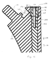
- Fig. 14 is a perspective, partially sectional, fragmentary view of another embodiment of a body and a stem, and an unlocking tool of the present invention;
- Fig. 15 is a front, sectional, fragmentary view of the body and stem of Fig. 14 in an assembled state;
- Fig. 16 is an enlarged view of the proximal ends of the body and stem of Fig. 14 in an assembled state;
- Fig. 17 is a front, sectional, fragmentary view of another embodiment of a body and a stem in an assembled state;
- Fig. 18 is a front, fragmentary view of the body and stem of Fig. 17; and
- Fig. 19 is a side, fragmentary view of the body and stem of Fig. 18 along line 19-19.
-
- Referring to the drawings, Fig. 1 shows a
modular trial assembly 20 according to one embodiment of the invention, including adistal stem 22, amain body 24, aplunger 26, acoil spring 28, astud 30 and aneck segment 32. Thestem 22 is separate from thebody 24, and theneck 32 is separate from thebody 24 and thestem 22. Theplunger 26, thecoil spring 28 and thestud 30 together form a locking mechanism. Thebody 24 and the locking mechanism together form a body assembly. Thetrial assembly 20 can preferably be made of stainless steel. However, it is possible to form thetrial assembly 20 of other materials, such as titanium, cobalt, etc. - As shown in Fig. 2, a
trial system kit 34 can include multiple sizes of each of thedistal stem 22, themain body 24 and theneck segment 32. More particularly, thekit 34 can include a small neck 32a, a large neck 32b, asmall body 24a, alarge body 24b, twosmall stems 22a, 22b, and a large stem 22c. Thekit 34 can also include multiple shapes of thestem 22. For instance, thestem 22a is straight while the stems 22b and 22c are bowed. Thus, different sizes and shapes of thestem 22, thebody 24 and theneck 32 can be mixed and matched with one another to produce amodular trial assembly 20 that matches the size and shape of the patient's joint anatomy. Various trial assemblies may be tried in order to ascertain which final implant will work best, in the surgeon's judgment. Regardless of which combination ofnecks 32,bodies 24 and stems 22 is used to assemble themodular trial assembly 20, the manner of assembly, which will be discussed in detail herein, is substantially the same. - Returning to Fig. 1, the
stem 22 includes adistal section 36 and a cylindricalproximal section 38. Thedistal section 36 is configured for implantation in a bore of a femur. Thedistal section 36 has a size and shape that is substantially the same as that of the implant for which thedistal section 36 trials. - The
proximal section 38 includes a key element in the form of atang 40, anannular groove 42, and two opposing recesses in the form ofslots 44. Eachslot 44 has a cross section with two right angles, as shown in Fig. 2. However, it is also possible for theslots 44 to have various cross-sectional shapes, such as V-shaped, U-shaped, etc. Eachslot 44 is oriented generally perpendicular to thetang 40. Anupper side 45 of theslot 44 is oriented at an angle of approximately 45° relative to the longitudinal axis of thestem 22. Theproximal section 38 has a diameter than is less than the diameter of thedistal section 36, thereby forming anannular shoulder 46 at their junction. Two stem anatomical references in the form ofinscriptions 47 are provided on the outer surface of theproximal section 38, with oneinscription 47 being below each ofslots 44. Each of theinscriptions 47 can identify thestem 22 as being one ofstems 22a, 22b and 22c, i.e., identifies the size and shape of thestem 22. - The
body 24 includes two intersecting throughchannels channel 48 has arectangular opening 52, best seen in Fig. 3, at aproximal end 54 of thebody 24. Thechannel 48 also has adistal opening 56 at adistal end 58 of thebody 24. Thechannel 48 is sized to receive theproximal section 38 of thestem 22. Theproximal opening 52 is configured to receive thetang 40 of thestem 22. - The
channel 50 is oriented parallel to the longitudinal axis of theneck 32. Thechannel 50 has anopening 60, best seen in Fig. 4, at amedial side 62 of thebody 24. Themedial side 62 is oriented at an angle of 45° relative to thechannel 48 and is oriented perpendicular to thechannel 50. This orientation allows themedial side 62 to interface with theneck 32. Anannular shoulder 63 disposed in thechannel 48 at themedial side 62 of thebody 24, and best seen in Fig. 5, defines theopening 60. In one aspect of the invention, the diameter of theopening 60 is smaller than the diameter of thechannel 50. Thechannel 50 also forms anopening 64, best seen in Figs. 6 and 7, at alateral side 66 of thebody 24. Theopening 64 is generally oval because thechannel 50 intersects thelateral side 66 at an angle. - The
medial side 62 of thebody 24 defines an L-shapedslot 68 adjacent theproximal end 54 and extending from ananterior side 70 to aposterior side 72 of thebody 24. As shown in Figs. 3 and 4, theslot 68 is generally perpendicular to the plane defined by thechannels proximal end 54 of thebody 24 also includes alinear slot 74. Theslot 74 includes and is an extension of theopening 52 of thechannel 48. Theslot 74 extends from thelateral side 66 toward themedial side 62 of thebody 24, parallel to the plane defined by thechannels slot 74 is in communication with thechannel 48 in order to receive thetang 40 of thestem 22. Theslot 74 is also in communication with the L-shapedslot 68 in order for theslot 74 to receive a portion of the neck, as will be discussed in more detail below. - The
lateral side 66 of thebody 24 includes an arcuate slot 76 (Fig. 7) extending from theanterior side 70 to theposterior side 72 of thebody 24, perpendicular to thechannel 48. Thearcuate slot 76 is in communication with both thelinear slot 74 and thechannel 48 in order to provide access to thestem 22 when thestem 22 is inserted into thebody 24, as will be discussed below. - Looking now at Figs. 1 and 4, the
plunger 26 includes a projection in the form of apin 78 extending from ahead 80. Thepin 78 is for insertion into a selected one of theslots 44 of thestem 22. Ashaft 82 havingexterior threads 84 extends from an opposite side of thehead 80. Theplunger 26 is sized to fit within thechannel 50. - The
spring 28 has a diameter greater than the diameter of theshaft 82 but less than the diameter of thehead 80. Further, the diameter of thespring 28 is greater than the diameter of theopening 60, and the diameter of theshaft 82 is less than the diameter of theopening 60. Thus, theshaft 82 will pass through theopening 60, but thespring 28 and thehead 80 will not pass through theopening 60. - The
stud 30 includes alateral end 86 having arecess 88 withinterior threads 90. The outer diameter of thelateral end 86 is greater than the diameter of theopening 60. Thethreads 90 have a size and spacing that allow thethreads 90 to receive thethreads 84 of theplunger 26. The outer surface of thestud 30 can include anannular groove 92 to allow an assembler to obtain a firm grip on thestud 30. - The
neck segment 32 includes acylindrical cavity 94 in alateral surface 96. Thecavity 94 is sized to receive thestud 30 therein. Theneck segment 32 also includes a block-shaped projection 98 (see Figs. 1 and 5) extending from thesurface 96. Another projection in the form of afin 100 is disposed partially on an upper surface of theprojection 98 and partially on atop surface 102 of theneck segment 32. Thefin 100 is oriented parallel to thecavity 94. Theprojection 98 and thefin 100 are for insertion into the L-shapedslot 68 and thelinear slot 74, respectively, to couple theneck 32 to thebody 24. - During assembly, the
spring 28 is inserted through theopening 64 and into thechannel 50. Theplunger 26 is then also inserted, threaded end first, through theopening 64 until thethreads 84 pass through thespring 28 and through theopening 60. Thestud 30 is placed at the position shown in Fig. 1, on the medial side of theopening 60. Thestud 30 is then coupled to theplunger 26 by virtue of theirmating threads stud 30 is accessible outside of thebody 24. - Once the
plunger 26 has been screwed into thestud 30, the surgeon or technician can manually grasp thestud 30 around thegroove 92 and pull thestud 30 in a medial direction, as indicated byarrow 104 in Fig. 4. The attachedplunger 26 is also pulled in thedirection 104 against the bias of thespring 28. As theplunger 26 moves, thehead 80 of theplunger 26 compresses thespring 28 against theshoulder 63 on which thespring 28 is seated. Thestud 30 is pulled indirection 104 until theplunger 26, including thepin 78, has passed through and is disposed inboard and clear of thechannel 48. At this point, the locking mechanism is in a releasing position. - The
stem 22, and particularly theportion 38, is then inserted into thechannel 48 through thedistal opening 56. Thestud 30 is held stationary, keeping theplunger 26 out of thechannel 48, while thetang 40 and thegroove 42 of theproximal section 38 pass by thechannel 50. Once thetang 40 has arrived at theproximal opening 52 of thechannel 48, thestem 22 is rotated if necessary so that thetang 40 is aligned with and can be inserted into thelinear slot 74 at theproximal end 54 of thebody 24. One of theinscriptions 47 is visible through theopening 64 when thetang 40 is aligned with and near theslot 74. Thus, the surgeon or technician can look for theinscription 47 through theopening 64 to determine if the tang is properly aligned with theslot 74. - If one of the bowed stems 22b or 22c is being inserted, it must be verified that the bow is oriented in the desired direction before the
tang 40 is inserted into theslot 74. If thetang 40 is inserted into theslot 74 with the bow in the wrong direction, thetang 40 must be withdrawn from theslot 74 and the stem rotated 180° before thetang 40 is reinserted into theslot 74. With thetang 40 in theslot 74, thestem 22 is prevented from rotating in thechannel 48. - The
stud 30 can be released and thelateral end 86 of thestud 30 becomes seated on theshoulder 63. The bias of thespring 28 pushes theplunger 26 in a lateral direction, opposite to thedirection 104, until thepin 78 of theplunger 26 is seated in aslot 44 of thestem 22. Thepin 78 thus locks, attaches or detachably connects thestem 22 within thebody 24. The locking mechanism is now in a locking position. - At this point, the
groove 42 of thestem 22 is aligned with theslot 76 of thebody 24, as best seen in Fig. 5. In addition, theinscription 47 is also visible through theopening 64, as best seen in Fig. 7. Thus, which of thestems 22a, 22b and 22c is locked to thebody 24 can be easily discerned by looking at theinscription 47 through theopening 64. Theshoulder 46 of thestem 22 is closely adjacent to, and is preferably in contact with, thedistal end 58 of thebody 24, as best seen in Fig. 6. The diameter of thestem 22 at theshoulder 46 is equal to the diameter of theend 58, thereby forming a seamless junction between them, which best mimics the smooth surface of the prosthesis for which theassembly 20 trials. - The
neck segment 32 is then placed on and unattachedly coupled to thebody 24. What is meant herein by "unattachedly coupled" is that theneck segment 32 is coupled to but not attached to thebody 24. For example, a single linear force, such as gravity, exerted on either theneck segment 32 or thebody 24, while the other of theneck segment 32 and thebody 24 is held stationary, can separate theneck segment 32 from thebody 24. - In order to unattachedly couple the
neck segment 32 to the body, thecavity 94 of theneck 32 is aligned with thestud 30, and thestud 30 is partially inserted into thecavity 94. Thefin 100 of theneck 32 is aligned with thelinear slot 74 of thebody 24, and theneck 32 is fully pressed onto thebody 24. Thefin 100 is received in theslot 74, the block-shapedprojection 98 is received in the L-shapedslot 68, and thestud 30 is fully received within thecavity 94. With thefin 100 in theslot 74, theneck 32 is prevented from rotating relative to thebody 24. The block-shapedprojection 98 in theslot 68 prevents theneck 32 from moving in the directions ofdouble arrow 105 in Fig. 5, thereby reducing force exerted on thestud 30 indirections 105 by theneck 32. - The
neck 32 is shown as includingprojections recesses body 24. However, in another embodiment (not shown), one or both of theprojections recesses - At this point, the
modular trial assembly 20 is fully assembled, as shown in Fig. 8. Animplant 106, for which theassembly 20 trials, is shown in Fig. 9. As can be seen in a comparison of Figs. 8 and 9, theassembly 20 closely mimics the size and shape of theimplant 106. - Before the
neck 32 is placed on thebody 24, the assembled combination of thebody 24 and thestem 22 can be placed into the medullary canal of the reamed out femur by use of ahandling tool 108 shown in Fig. 10. Thetool 108 includes acavity 110, an L-shapedlatch 112, and afin 114 that emulate the like features of theneck 32. Thestud 30 can thus be received in thecavity 110, the L-shapedlatch 112 can reside within the L-shapedcavity slot 68, and thefin 114 can slide into thelinear slot 74. - During use, a first step in attaching the
tool 108 to thebody 24 includes aligning thetool 108 to thebody 24 with a trigger 115 (Fig. 11) in an unsqueezed or unactuated position. Thus, a simultaneous alignment of thecavity 110 with thestud 30, thelatch 112 with theslot 68, and thefin 114 with theslot 74 can be achieved. With the above elements simultaneously aligned, thetool 108 is advanced onto thebody 24 such that thestud 30 is received in thecavity 110, thelatch 112 is received in theslot 68, and thefin 114 is received in theslot 74. Thetrigger 115 is then squeezed or otherwise actuated to push a connectingrod 116 in adirection 118, thereby pivoting thelatch 112 attached to therod 116 about apivot 120. Thus, the distal end of thelatch 112 is hooked or latched into the L-shapedslot 68, as shown in Fig. 10. With thetool 108 thus attached to thebody 24, thetool 108 can be used to insert the assembled combination of thebody 24 and thestem 22 into the reamed out femur. - By using a procedure substantially the reverse of that described above, the
tool 108 can also be used to extract the assembled combination of thebody 24 and thestem 22 from the reamed out femur. Another tool (not shown) is placed in the alignedslot 76 andgroove 42 during the extraction process. Further, thetool 108 can also place or extract a broaching apparatus 122 (Fig. 12), which is used in the reamed out femur. - The proximal end of the
broaching apparatus 122 is configured similarly to theproximal end 54 of thebody 24 for connection to thetool 108. More particularly, the broachingapparatus 122 includes aprojection 124, an L-shapedslot 126, and a linear slot 128 (Fig. 13) for coupling with thecavity 110, the L-shapedlatch 112, and thefin 114, respectively, of thetool 108. - It is also possible, in another embodiment, for the
trial body 24 of themodular trial assembly 20 to be provided with serrated teeth, similarly to thebroaching apparatus 122. Thus, themodular trial assembly 20 can function both as a trial assembly and as a broaching device. - In another embodiment (Fig. 14) a
stem 130 is attachable to abody 132. An unlockingtool 134 unlocks thestem 130 from thebody 132 so that thestem 130 can be separated from thebody 132. - The
stem 130 includes aproximal section 136 and adistal section 138 for implantation in a bone. Theproximal section 136 includes two resilient members in the form of opposing taperedprongs 140. Theprongs 140 are separated by agap 142. Aproximal end 144 of thedistal section 138 includes a projection ortab 146, best seen in Fig. 15. Each of theprongs 140 includes a latch 148 (Fig. 16) where the surface of theprong 140 is perpendicular to alongitudinal axis 150 of thestem 130. - The
body 132 includes a throughchannel 152 having aproximal opening 154 at aproximal end 156 of thebody 132, and adistal opening 158 at adistal end 160 of thebody 132. The width or diameter of theopening 154 of the throughchannel 152 at thedistal end 160 is greater than the width or diameter of theproximal section 136 of thestem 130, but is less than the width or diameter of theproximal end 144 of thedistal section 138 of thestem 130. Thedistal end 160 includes a recess orcavity 162 in communication with the throughchannel 152. Thecavity 162 is sized to receive thetab 146. - The through
channel 152 includes anannular catch 164 where the surface defining the throughchannel 152 is perpendicular to alongitudinal axis 166 of the throughchannel 152. The diameter or width of the throughchannel 152 above, or disposed proximally of, thecatch 164 is greater than the diameter or width of the throughchannel 152 below, or disposed distally of, thecatch 164. The proximal end of thebody 132 includes an L-shapedslot 168 and aprojection 170 for unattached, non-rotatable coupling to a neck (not shown), as discussed in detail with regard to the previous embodiment. - During use,
thin portions 172 of theprongs 140 are inserted into thedistal opening 158 of the throughchannel 152. As theprongs 140 move in aproximal direction 174 through the throughchannel 152,thick portions 176 of theprongs 140 engage the wall of the throughchannel 152, and theprongs 140 are biassed toward each other by the wall of the throughchannel 152. Thestem 130 is rotated, if necessary, about itsaxis 150 such that thetab 146 is aligned with thecavity 162 of the body. Farther advancement of thestem 130 in theproximal direction 174 results in thetab 146 being received in thecavity 162. The coupling of thetab 146 and thecavity 162 prevents thestem 130 from rotating about itsaxis 150 within the throughchannel 152. - When the
latches 148 of theprongs 140 move past thecatch 164 of the throughchannel 152 inproximal direction 174, theprongs 140 spring outwardly and are no longer biassed by the wall of the throughchannel 152. At this point, theproximal end 144 of thedistal section 138 engages thedistal end 160 of thebody 132, thereby limiting further movement of theprongs 140 in theproximal direction 174. - If an attempt is now made to move the
stem 130 in adistal direction 178, opposite to theproximal direction 174, thelatches 148 of theprongs 140 latch onto thecatch 164 and prevent theprongs 140 from passing by thecatch 164 in thedistal direction 178. Thus, thestem 130 is locked to thebody 132. More particularly, thestem 130 is prevented from moving in either ofdirections axis 150. - The unlocking
tool 134 is a hollow, annular device with two open opposite ends 180. In order to unlock thestem 130 from thebody 132, one of theends 180 is inserted through theproximal opening 154 of the throughchannel 152. Theopen end 180 becomes seated over thethin portions 172 of theprongs 140. Farther movement of thetool 134 in thedistal direction 178 causes theopen end 180 to bias the twoprongs 140 toward one another such that thelatches 148 are no longer latched on thecatch 164. Thetool 134 can be sized such that theopen end 180 becomes seated on thecatch 164. Thestem 130 can then be pulled in thedistal direction 178 by itsdistal section 138 and can be withdrawn from the throughchannel 152. - In another embodiment (Fig. 17), a
body 232 is attached to astem 230 of two-piece construction. That is, thestem 230 has aproximal section 236 that is detachable from thedistal section 238. Thedistal section 238 includes abore 280 for receiving the distal end of theproximal section 236. Thedistal section 238 also includes athroughhole 282, best seen in Figs. 18 and 19, extending through thebore 280. Thethroughhole 282 can be aligned with a throughhole 284 in the distal end of theproximal section 236 for receiving apin 286 in each of thethroughholes pin 286 attaches theproximal section 236 and thedistal section 238 of thestem 230. - After the
proximal section 236 and thedistal section 238 of thestem 230 have been attached by insertion of thepin 286, thestem 230 can be locked to thebody 232 by the method described above with regard to Figs. 14-16. Alternatively, it is also possible to insert theproximal section 236 through aproximal opening 254 of the throughchannel 252 before theproximal section 236 has been attached to thedistal section 238. That is, theproximal section 236 can be inserted through theproximal opening 254, distal end first, until thelatches 248 come to rest on or latch onto thecatch 262. At this point, adistal end 288 of theproximal section 236 extends out of thedistal end 258 of thebody 232. Thedistal section 238 is coupled to theproximal section 236 by aligning thebore 280 with thedistal end 288 of theproximal section 236 and receiving thedistal end 288 in thebore 280. Thepin 286 is inserted through thethroughholes proximal section 236 to thedistal section 238. - It should be appreciated that the modular trial assembly described herein is for use during performance of a joint replacement procedure such as a hip replacement procedure. Therefore, although the present invention is herein described in regard to performance of an exemplary hip replacement procedure, certain of the concepts of the present invention may be utilized in regard to replacement procedures at numerous other joint locations throughout the body.
Claims (10)
- A prosthetic trial for a joint prosthesis, comprising:a stem having a proximal section and a distal section configured for implantation in a bone;a body including a first channel configured to receive at least said proximal section of said stem; anda locking mechanism at least partially disposed within said body, said locking mechanism biassed into a locking position in which said locking mechanism locks said stem within said first channel of said body and accessible outside said body to be pulled into a releasing position to unlock said stem from said body.
- The trial of claim 1, wherein said body includes a second channel, said locking mechanism being at least partially disposed within said second channel.
- The trial of claim 2, wherein said second channel intersects said first channel.
- The trial of claim 1, wherein said stem includes a recess receiving at least a portion of said locking mechanism when said locking mechanism is in the locking position.
- The trial of claim 4, wherein said locking mechanism includes a spring and a projection, said spring biassing said projection into said recess of said stem.
- The trial of claim 5, wherein said spring is disposed within said second channel.
- The trial of claim 5, wherein said second channel includes a shoulder, said locking mechanism including a head attached to said projection, a first end of said spring being seated against said shoulder, a second end of said spring engaging said head
- The trial of claim 5, wherein said locking mechanism includes a stud attached to said projection, said stud being configured to be pulled into the releasing position, the projection being disposed out of said recess when said stud is in the releasing position.
- The trial of claim 8, wherein said locking mechanism includes:a head attached to said projection;a shaft interconnecting said head and said stud, said spring substantially surrounding said shaft.
- The trial of claim 9, wherein said second channel includes a shoulder, said stud being seated against said shoulder.
Priority Applications (1)
| Application Number | Priority Date | Filing Date | Title |
|---|---|---|---|
| EP09158543.0A EP2077098B1 (en) | 2002-09-30 | 2003-09-09 | Modular trial mechanism |
Applications Claiming Priority (2)
| Application Number | Priority Date | Filing Date | Title |
|---|---|---|---|
| US10/260,137 US7273499B2 (en) | 2002-09-30 | 2002-09-30 | Modular trial mechanism |
| US260137 | 2002-09-30 |
Related Child Applications (2)
| Application Number | Title | Priority Date | Filing Date |
|---|---|---|---|
| EP09158543.0A Division EP2077098B1 (en) | 2002-09-30 | 2003-09-09 | Modular trial mechanism |
| EP09158543.0 Division-Into | 2009-04-22 |
Publications (3)
| Publication Number | Publication Date |
|---|---|
| EP1410771A2 true EP1410771A2 (en) | 2004-04-21 |
| EP1410771A3 EP1410771A3 (en) | 2005-11-09 |
| EP1410771B1 EP1410771B1 (en) | 2010-10-27 |
Family
ID=32029618
Family Applications (2)
| Application Number | Title | Priority Date | Filing Date |
|---|---|---|---|
| EP09158543.0A Expired - Lifetime EP2077098B1 (en) | 2002-09-30 | 2003-09-09 | Modular trial mechanism |
| EP03255598A Expired - Lifetime EP1410771B1 (en) | 2002-09-30 | 2003-09-09 | Trial for medical prosthesis |
Family Applications Before (1)
| Application Number | Title | Priority Date | Filing Date |
|---|---|---|---|
| EP09158543.0A Expired - Lifetime EP2077098B1 (en) | 2002-09-30 | 2003-09-09 | Modular trial mechanism |
Country Status (4)
| Country | Link |
|---|---|
| US (2) | US7273499B2 (en) |
| EP (2) | EP2077098B1 (en) |
| AT (1) | ATE485792T1 (en) |
| DE (1) | DE60334667D1 (en) |
Families Citing this family (45)
| Publication number | Priority date | Publication date | Assignee | Title |
|---|---|---|---|---|
| US7297166B2 (en) | 2003-06-25 | 2007-11-20 | Depuy Products, Inc. | Assembly tool for modular implants and associated method |
| US7074224B2 (en) * | 2003-06-25 | 2006-07-11 | Depuy Products, Inc. | Modular tapered reamer for bone preparation and associated method |
| US8998919B2 (en) | 2003-06-25 | 2015-04-07 | DePuy Synthes Products, LLC | Assembly tool for modular implants, kit and associated method |
| US7582092B2 (en) | 2003-06-25 | 2009-09-01 | Depuy Products, Inc. | Assembly tool for modular implants and associated method |
| US7785328B2 (en) * | 2003-12-30 | 2010-08-31 | Depuy Products, Inc. | Minimally invasive bone miller apparatus |
| US7641698B1 (en) * | 2004-06-04 | 2010-01-05 | Biomet Manufacturing Corp. | Modular hip joint implant |
| US7476253B1 (en) * | 2004-08-11 | 2009-01-13 | Biomet Manufacturing Corporation | Humeral head preserving implant |
| GB0420346D0 (en) * | 2004-09-13 | 2004-10-13 | Finsbury Dev Ltd | Tool |
| US20070050041A1 (en) * | 2005-08-30 | 2007-03-01 | Dietz Terry L | Orthopaedic implant stem component, joint component, and associated kit |
| US8597298B2 (en) | 2006-09-29 | 2013-12-03 | DePuy Synthes Products, LLC | Proximal reamer |
| US7585329B2 (en) * | 2006-11-28 | 2009-09-08 | Depuy Products, Inc. | Modular proximal body trial |
| US8579985B2 (en) * | 2006-12-07 | 2013-11-12 | Ihip Surgical, Llc | Method and apparatus for hip replacement |
| WO2008069800A1 (en) * | 2006-12-07 | 2008-06-12 | Anatol Podolsky | Method and apparatus for total hip replacement |
| US8974540B2 (en) | 2006-12-07 | 2015-03-10 | Ihip Surgical, Llc | Method and apparatus for attachment in a modular hip replacement or fracture fixation device |
| GB0716403D0 (en) * | 2007-08-22 | 2007-10-03 | Benoist Girard Sas | Trial prosthetic neck component |
| WO2009046121A2 (en) * | 2007-10-01 | 2009-04-09 | Smith & Nephew, Inc. | Method and apparatus for preparing bone for a prosthetic device |
| US8556912B2 (en) | 2007-10-30 | 2013-10-15 | DePuy Synthes Products, LLC | Taper disengagement tool |
| US8518050B2 (en) | 2007-10-31 | 2013-08-27 | DePuy Synthes Products, LLC | Modular taper assembly device |
| RU2011104182A (en) * | 2008-07-08 | 2012-08-20 | Смит Энд Нефью, Инк. (Us) | MINIMALLY INVASIVE SURGICAL INSTRUMENTS FOR IMPLANTATION OF HIP JOINT PROSTHESIS |
| US8702805B2 (en) * | 2008-07-21 | 2014-04-22 | Harutaro Trabish | Acetabulum surgical resurfacing aid |
| US8167882B2 (en) | 2008-09-30 | 2012-05-01 | Depuy Products, Inc. | Minimally invasive bone miller apparatus |
| US8252002B2 (en) * | 2009-10-30 | 2012-08-28 | Depuy Products, Inc. | Modular trial mechanism |
| US8968411B2 (en) * | 2009-12-17 | 2015-03-03 | Zimmer, Inc. | Modular elbow prosthesis |
| US8533921B2 (en) | 2010-06-15 | 2013-09-17 | DePuy Synthes Products, LLC | Spiral assembly tool |
| US9095452B2 (en) | 2010-09-01 | 2015-08-04 | DePuy Synthes Products, Inc. | Disassembly tool |
| US9597188B2 (en) * | 2011-04-06 | 2017-03-21 | DePuy Synthes Products, Inc. | Version-replicating instrument and orthopaedic surgical procedure for using the same to implant a revision hip prosthesis |
| US9421106B2 (en) | 2011-12-07 | 2016-08-23 | Howmedica Osteonics Corp. | Reverse shoulder baseplate with alignment guide for glenosphere |
| US8906102B2 (en) * | 2012-05-31 | 2014-12-09 | Howmedica Osteonics Corp. | Lateral entry insert for cup trial |
| US10201374B2 (en) | 2012-06-22 | 2019-02-12 | Zimmer, Inc. | Assembly tool for a prosthesis |
| US8936647B2 (en) | 2012-06-22 | 2015-01-20 | Zimmer, Inc. | Elbow prosthesis |
| JP2018504989A (en) * | 2015-02-13 | 2018-02-22 | ハートウェア、インコーポレイテッド | Complex tunnel drilling equipment |
| US9597203B2 (en) * | 2015-03-25 | 2017-03-21 | Tornier, Inc. | Modular humeral implant |
| CN106880424A (en) * | 2015-12-16 | 2017-06-23 | 重庆润泽医药有限公司 | A kind of artificial shoulder joint prosthesis |
| CN106913404B (en) * | 2015-12-25 | 2019-02-19 | 重庆润泽医药有限公司 | A kind of compound hip joint |
| CN106913395B (en) * | 2015-12-25 | 2019-02-19 | 重庆润泽医药有限公司 | A kind of bion hip joint |
| CN106913401B (en) * | 2015-12-25 | 2019-02-19 | 重庆润泽医药有限公司 | A kind of multisection type hip joint |
| CN106913399B (en) * | 2015-12-25 | 2019-02-19 | 重庆润泽医药有限公司 | A kind of buffer-type hip joint |
| US10390972B2 (en) | 2016-01-15 | 2019-08-27 | Howmedica Osteonics Corp. | Humeral trial adaptor |
| GB201705917D0 (en) | 2017-04-12 | 2017-05-24 | Davidson Craig | Femoral trialling kit and assembly |
| EP3672534A1 (en) | 2017-08-22 | 2020-07-01 | DePuy Ireland Unlimited Company | Trial neck |
| GB201716107D0 (en) * | 2017-10-03 | 2017-11-15 | Depuy Ireland Ultd Co | Trial neck apparatus and method |
| CA3102265A1 (en) * | 2018-06-01 | 2019-12-05 | Memorial Sloan Kettering Cancer Center | Convertible intramedullary femoral nail and use thereof for management of metastatic cancer to bone |
| US11129733B2 (en) * | 2019-05-01 | 2021-09-28 | Stephen Patrick Morrisey | Hip arthroplasty trial systems and associated medical devices, methods, and kits |
| EP3771442A1 (en) * | 2019-07-31 | 2021-02-03 | Ostium Group | Modular tool |
| EP3771443B1 (en) | 2019-07-31 | 2022-04-06 | Ostium Group | Tool holder for modular tool |
Citations (1)
| Publication number | Priority date | Publication date | Assignee | Title |
|---|---|---|---|---|
| EP0558203A1 (en) | 1992-02-20 | 1993-09-01 | Wright Medical Technology, Inc. | Modular trial instrument with interlock mechanism |
Family Cites Families (52)
| Publication number | Priority date | Publication date | Assignee | Title |
|---|---|---|---|---|
| US643210A (en) * | 1899-10-06 | 1900-02-13 | Albert Dewey Tomlinson | Sofa-bed. |
| US3918441A (en) * | 1974-09-17 | 1975-11-11 | Philip E Getscher | Intramedullary hip pin |
| US4135517A (en) * | 1977-07-21 | 1979-01-23 | Minnesota Mining And Manufacturing Company | Femoral prosthesis trial fitting device |
| US4163292A (en) * | 1977-11-21 | 1979-08-07 | Averett James E Jr | Hip prosthesis |
| DE3417609A1 (en) * | 1984-05-11 | 1985-11-14 | Waldemar Link (Gmbh & Co), 2000 Hamburg | ARRANGEMENT FOR PRODUCING ANATOMICALLY APPROPRIATE ENDOPROTHESIS |
| US4601289A (en) * | 1985-04-02 | 1986-07-22 | Dow Corning Wright | Femoral trial prosthesis/rasp assembly |
| DE3774799D1 (en) * | 1986-08-15 | 1992-01-09 | Boehringer Mannheim Corp., Indianapolis, Ind., Us | |
| US5080685A (en) * | 1986-08-15 | 1992-01-14 | Boehringer Mannheim Corporation | Modular hip prosthesis |
| DE8703491U1 (en) * | 1987-03-09 | 1987-04-23 | Waldemar Link Gmbh & Co, 2000 Hamburg, De | |
| DE8708500U1 (en) * | 1987-06-12 | 1988-04-14 | Mecron Medizinische Produkte Gmbh, 1000 Berlin, De | |
| US5108437A (en) * | 1988-09-14 | 1992-04-28 | Pfizer Hospital Products Group, Inc. | Modular prosthesis |
| US5108452A (en) * | 1989-02-08 | 1992-04-28 | Smith & Nephew Richards Inc. | Modular hip prosthesis |
| DE8903850U1 (en) * | 1989-03-21 | 1989-06-01 | Orthoplant Endoprothetik Gmbh, 2800 Bremen, De | |
| US4963155A (en) * | 1989-08-30 | 1990-10-16 | Zimmer, Inc. | Attachment mechanism for modular surgical products |
| US5030234A (en) * | 1989-12-12 | 1991-07-09 | Pappas Michael J | Prosthetic device with modular stem |
| US5074879A (en) * | 1990-10-26 | 1991-12-24 | Pappas Michael J | Prosthetic device with modular stem |
| FR2660857B1 (en) | 1990-04-11 | 1997-12-12 | Astel Sarl | DEVICE FOR ASSEMBLING A PROSTHETIC TEST HEAD. |
| US5002578A (en) * | 1990-05-04 | 1991-03-26 | Venus Corporation | Modular hip stem prosthesis apparatus and method |
| US5100407A (en) * | 1990-09-04 | 1992-03-31 | Pfizer Hospital Products Group, Inc. | Modular trial hip replacement system |
| US5342366A (en) * | 1992-02-19 | 1994-08-30 | Biomet, Inc. | Surgical instruments for hip revision |
| CH685533A5 (en) * | 1992-10-13 | 1995-08-15 | Philipp Rolf Kropf Albert Geis | Modular hip prosthesis stem. |
| US5507817A (en) * | 1994-02-22 | 1996-04-16 | Kirschner Medical Corporation | Modular humeral prosthesis for reconstruction of the humerus |
| AU2351395A (en) * | 1994-06-30 | 1996-01-25 | Howmedica Inc. | Modular femoral trial hip replacement system |
| US5653765A (en) * | 1994-07-01 | 1997-08-05 | Ortho Development Corporation | Modular prosthesis |
| US5569263A (en) * | 1995-01-12 | 1996-10-29 | Orthopaedic Innovations, Inc. | Adjustable provisional articulating device |
| US5474879A (en) * | 1995-01-30 | 1995-12-12 | Eastman Kodak Company | Radiographic film developers containing ascorbic acid and thioether development accelerators |
| JPH08221931A (en) * | 1995-02-20 | 1996-08-30 | Fuji Photo Film Co Ltd | Magnetic disk cartridge |
| US5645607A (en) * | 1995-03-02 | 1997-07-08 | Zimmer, Inc. | Hip stem provisional having adjustable neck offsets |
| US5766261A (en) * | 1996-02-01 | 1998-06-16 | Osteonics Corp. | Femoral revision broach with modular trial components and method |
| US5800556A (en) | 1996-05-23 | 1998-09-01 | Johnson & Johnson Professional, Inc. | Adjustable bipolar-unipolar adaptor for a head trial |
| US5876459A (en) * | 1996-08-30 | 1999-03-02 | Powell; Douglas Hunter | Adjustable modular orthopedic implant |
| US5906644A (en) * | 1996-08-30 | 1999-05-25 | Powell; Douglas Hunter | Adjustable modular orthopedic implant |
| US5725592A (en) * | 1996-10-29 | 1998-03-10 | Hayes Medical, Inc. | Modular prosthesis having neck component connected to stem component through cavity in body component |
| US5860982A (en) * | 1997-03-26 | 1999-01-19 | Johnson & Johnson Professional, Inc. | Cemented calcar replacement varying height trial |
| US5951603A (en) * | 1997-09-25 | 1999-09-14 | Johnson & Johnson Professional, Inc. | Rotatable joint prosthesis with axial securement |
| US6494913B1 (en) * | 1998-03-17 | 2002-12-17 | Acumed, Inc. | Shoulder prosthesis |
| US6428578B2 (en) * | 1998-03-18 | 2002-08-06 | Sct Incorporated | Modular prosthesis and connector therefor |
| US6206884B1 (en) | 1998-07-15 | 2001-03-27 | Medidea, Llc | Reduction-based joint replacement apparatus and methods |
| DE19852848C1 (en) | 1998-11-11 | 2000-08-24 | Klaus Affeld | Method for forming an infection protection cuff for the passage of a channel through the skin into the interior of the body and device therefor |
| US6264699B1 (en) * | 1998-11-23 | 2001-07-24 | Depuy Orthopaedics, Inc. | Modular stem and sleeve prosthesis |
| FR2796267B1 (en) | 1999-07-13 | 2001-09-28 | Protheos Ind | FEMALE PROSTHESIS TEST NECK |
| US6270529B1 (en) * | 1999-09-01 | 2001-08-07 | Wright Medical Technology, Inc. | Modular implant for replacing end of radius and having drainage passage for trapped fluid |
| US6589282B2 (en) * | 1999-12-31 | 2003-07-08 | Implex Corporation | Modular shoulder prostheses |
| US6382977B1 (en) * | 2000-03-02 | 2002-05-07 | Nobel Biocare Usa, Inc. | Snap-in impression coping |
| US6319286B1 (en) * | 2000-03-13 | 2001-11-20 | Exactech, Inc | Modular hip prosthesis |
| US6299648B1 (en) * | 2000-03-17 | 2001-10-09 | Hammill Manufacturing Co. | Locking hip prosthesis |
| US6676706B1 (en) * | 2000-04-26 | 2004-01-13 | Zimmer Technology, Inc. | Method and apparatus for performing a minimally invasive total hip arthroplasty |
| WO2001082843A2 (en) | 2000-05-03 | 2001-11-08 | Smith & Nephew, Inc. | Multi modular trialing system and instrumentation |
| WO2002005728A2 (en) * | 2000-07-18 | 2002-01-24 | Biomet Inc. | Elbow prosthesis |
| US6440171B1 (en) * | 2001-02-27 | 2002-08-27 | Hammill Manuf. Co. | Double D key locking prosthesis |
| US6355068B1 (en) * | 2001-06-07 | 2002-03-12 | Hammill Manufacturing Co. | Sight gauge modular joint and method |
| US6875239B2 (en) * | 2002-04-25 | 2005-04-05 | Medicinelodge, Inc. | Modular prosthesis for replacing bone and method |
-
2002
- 2002-09-30 US US10/260,137 patent/US7273499B2/en active Active
-
2003
- 2003-09-09 AT AT03255598T patent/ATE485792T1/en not_active IP Right Cessation
- 2003-09-09 DE DE60334667T patent/DE60334667D1/en not_active Expired - Lifetime
- 2003-09-09 EP EP09158543.0A patent/EP2077098B1/en not_active Expired - Lifetime
- 2003-09-09 EP EP03255598A patent/EP1410771B1/en not_active Expired - Lifetime
-
2007
- 2007-08-29 US US11/897,222 patent/US7828851B2/en not_active Expired - Lifetime
Patent Citations (1)
| Publication number | Priority date | Publication date | Assignee | Title |
|---|---|---|---|---|
| EP0558203A1 (en) | 1992-02-20 | 1993-09-01 | Wright Medical Technology, Inc. | Modular trial instrument with interlock mechanism |
Also Published As
| Publication number | Publication date |
|---|---|
| EP2077098B1 (en) | 2015-06-03 |
| US20070299527A1 (en) | 2007-12-27 |
| US7828851B2 (en) | 2010-11-09 |
| US20040064186A1 (en) | 2004-04-01 |
| DE60334667D1 (en) | 2010-12-09 |
| EP1410771B1 (en) | 2010-10-27 |
| ATE485792T1 (en) | 2010-11-15 |
| US7273499B2 (en) | 2007-09-25 |
| EP2077098A2 (en) | 2009-07-08 |
| EP1410771A3 (en) | 2005-11-09 |
| EP2077098A3 (en) | 2009-10-07 |
Similar Documents
| Publication | Publication Date | Title |
|---|---|---|
| US7828851B2 (en) | Modular trial mechanism | |
| EP0931524B1 (en) | Modular long stem hip trial | |
| AU2021209337B2 (en) | Revision knee arthroplasty methods and instruments | |
| CA2193689C (en) | Modular femoral trial hip replacement system | |
| US8337502B2 (en) | Compound offset handle | |
| CA2089734C (en) | Modular trial hip replacement system | |
| US4963155A (en) | Attachment mechanism for modular surgical products | |
| US7981161B2 (en) | Disposable neck trial adapter | |
| EP2567676A1 (en) | Expandable reverse shoulder trial | |
| US20080033444A1 (en) | Compound offset handle | |
| EP2316388B1 (en) | Modular trial mechanism | |
| EP1234558B1 (en) | Modular hip trial for long stems |
Legal Events
| Date | Code | Title | Description |
|---|---|---|---|
| PUAI | Public reference made under article 153(3) epc to a published international application that has entered the european phase |
Free format text: ORIGINAL CODE: 0009012 |
|
| AK | Designated contracting states |
Kind code of ref document: A2 Designated state(s): AT BE BG CH CY CZ DE DK EE ES FI FR GB GR HU IE IT LI LU MC NL PT RO SE SI SK TR |
|
| AX | Request for extension of the european patent |
Extension state: AL LT LV MK |
|
| PUAL | Search report despatched |
Free format text: ORIGINAL CODE: 0009013 |
|
| AK | Designated contracting states |
Kind code of ref document: A3 Designated state(s): AT BE BG CH CY CZ DE DK EE ES FI FR GB GR HU IE IT LI LU MC NL PT RO SE SI SK TR |
|
| AX | Request for extension of the european patent |
Extension state: AL LT LV MK |
|
| 17P | Request for examination filed |
Effective date: 20060322 |
|
| AKX | Designation fees paid |
Designated state(s): AT BE BG CH CY CZ DE DK EE ES FI FR GB GR HU IE IT LI LU MC NL PT RO SE SI SK TR |
|
| 17Q | First examination report despatched |
Effective date: 20071002 |
|
| RTI1 | Title (correction) |
Free format text: TRIAL FOR MEDICAL PROSTHESIS |
|
| GRAP | Despatch of communication of intention to grant a patent |
Free format text: ORIGINAL CODE: EPIDOSNIGR1 |
|
| GRAS | Grant fee paid |
Free format text: ORIGINAL CODE: EPIDOSNIGR3 |
|
| GRAA | (expected) grant |
Free format text: ORIGINAL CODE: 0009210 |
|
| AK | Designated contracting states |
Kind code of ref document: B1 Designated state(s): AT BE BG CH CY CZ DE DK EE ES FI FR GB GR HU IE IT LI LU MC NL PT RO SE SI SK TR |
|
| REG | Reference to a national code |
Ref country code: GB Ref legal event code: FG4D |
|
| REG | Reference to a national code |
Ref country code: CH Ref legal event code: EP |
|
| REG | Reference to a national code |
Ref country code: IE Ref legal event code: FG4D |
|
| REG | Reference to a national code |
Ref country code: CH Ref legal event code: NV Representative=s name: E. BLUM & CO. AG PATENT- UND MARKENANWAELTE VSP |
|
| REF | Corresponds to: |
Ref document number: 60334667 Country of ref document: DE Date of ref document: 20101209 Kind code of ref document: P |
|
| REG | Reference to a national code |
Ref country code: NL Ref legal event code: VDEP Effective date: 20101027 |
|
| PG25 | Lapsed in a contracting state [announced via postgrant information from national office to epo] |
Ref country code: SI Free format text: LAPSE BECAUSE OF FAILURE TO SUBMIT A TRANSLATION OF THE DESCRIPTION OR TO PAY THE FEE WITHIN THE PRESCRIBED TIME-LIMIT Effective date: 20101027 Ref country code: AT Free format text: LAPSE BECAUSE OF FAILURE TO SUBMIT A TRANSLATION OF THE DESCRIPTION OR TO PAY THE FEE WITHIN THE PRESCRIBED TIME-LIMIT Effective date: 20101027 Ref country code: FI Free format text: LAPSE BECAUSE OF FAILURE TO SUBMIT A TRANSLATION OF THE DESCRIPTION OR TO PAY THE FEE WITHIN THE PRESCRIBED TIME-LIMIT Effective date: 20101027 Ref country code: BG Free format text: LAPSE BECAUSE OF FAILURE TO SUBMIT A TRANSLATION OF THE DESCRIPTION OR TO PAY THE FEE WITHIN THE PRESCRIBED TIME-LIMIT Effective date: 20110127 Ref country code: NL Free format text: LAPSE BECAUSE OF FAILURE TO SUBMIT A TRANSLATION OF THE DESCRIPTION OR TO PAY THE FEE WITHIN THE PRESCRIBED TIME-LIMIT Effective date: 20101027 Ref country code: PT Free format text: LAPSE BECAUSE OF FAILURE TO SUBMIT A TRANSLATION OF THE DESCRIPTION OR TO PAY THE FEE WITHIN THE PRESCRIBED TIME-LIMIT Effective date: 20110228 Ref country code: SE Free format text: LAPSE BECAUSE OF FAILURE TO SUBMIT A TRANSLATION OF THE DESCRIPTION OR TO PAY THE FEE WITHIN THE PRESCRIBED TIME-LIMIT Effective date: 20101027 |
|
| PG25 | Lapsed in a contracting state [announced via postgrant information from national office to epo] |
Ref country code: BE Free format text: LAPSE BECAUSE OF FAILURE TO SUBMIT A TRANSLATION OF THE DESCRIPTION OR TO PAY THE FEE WITHIN THE PRESCRIBED TIME-LIMIT Effective date: 20101027 Ref country code: GR Free format text: LAPSE BECAUSE OF FAILURE TO SUBMIT A TRANSLATION OF THE DESCRIPTION OR TO PAY THE FEE WITHIN THE PRESCRIBED TIME-LIMIT Effective date: 20110128 |
|
| PG25 | Lapsed in a contracting state [announced via postgrant information from national office to epo] |
Ref country code: EE Free format text: LAPSE BECAUSE OF FAILURE TO SUBMIT A TRANSLATION OF THE DESCRIPTION OR TO PAY THE FEE WITHIN THE PRESCRIBED TIME-LIMIT Effective date: 20101027 Ref country code: CZ Free format text: LAPSE BECAUSE OF FAILURE TO SUBMIT A TRANSLATION OF THE DESCRIPTION OR TO PAY THE FEE WITHIN THE PRESCRIBED TIME-LIMIT Effective date: 20101027 Ref country code: ES Free format text: LAPSE BECAUSE OF FAILURE TO SUBMIT A TRANSLATION OF THE DESCRIPTION OR TO PAY THE FEE WITHIN THE PRESCRIBED TIME-LIMIT Effective date: 20110207 |
|
| PG25 | Lapsed in a contracting state [announced via postgrant information from national office to epo] |
Ref country code: DK Free format text: LAPSE BECAUSE OF FAILURE TO SUBMIT A TRANSLATION OF THE DESCRIPTION OR TO PAY THE FEE WITHIN THE PRESCRIBED TIME-LIMIT Effective date: 20101027 Ref country code: RO Free format text: LAPSE BECAUSE OF FAILURE TO SUBMIT A TRANSLATION OF THE DESCRIPTION OR TO PAY THE FEE WITHIN THE PRESCRIBED TIME-LIMIT Effective date: 20101027 Ref country code: SK Free format text: LAPSE BECAUSE OF FAILURE TO SUBMIT A TRANSLATION OF THE DESCRIPTION OR TO PAY THE FEE WITHIN THE PRESCRIBED TIME-LIMIT Effective date: 20101027 |
|
| PLBE | No opposition filed within time limit |
Free format text: ORIGINAL CODE: 0009261 |
|
| STAA | Information on the status of an ep patent application or granted ep patent |
Free format text: STATUS: NO OPPOSITION FILED WITHIN TIME LIMIT |
|
| 26N | No opposition filed |
Effective date: 20110728 |
|
| REG | Reference to a national code |
Ref country code: DE Ref legal event code: R097 Ref document number: 60334667 Country of ref document: DE Effective date: 20110728 |
|
| PG25 | Lapsed in a contracting state [announced via postgrant information from national office to epo] |
Ref country code: IT Free format text: LAPSE BECAUSE OF FAILURE TO SUBMIT A TRANSLATION OF THE DESCRIPTION OR TO PAY THE FEE WITHIN THE PRESCRIBED TIME-LIMIT Effective date: 20101027 |
|
| PG25 | Lapsed in a contracting state [announced via postgrant information from national office to epo] |
Ref country code: MC Free format text: LAPSE BECAUSE OF NON-PAYMENT OF DUE FEES Effective date: 20110930 |
|
| PG25 | Lapsed in a contracting state [announced via postgrant information from national office to epo] |
Ref country code: LU Free format text: LAPSE BECAUSE OF NON-PAYMENT OF DUE FEES Effective date: 20110909 Ref country code: CY Free format text: LAPSE BECAUSE OF EXPIRATION OF PROTECTION Effective date: 20101027 |
|
| PG25 | Lapsed in a contracting state [announced via postgrant information from national office to epo] |
Ref country code: TR Free format text: LAPSE BECAUSE OF FAILURE TO SUBMIT A TRANSLATION OF THE DESCRIPTION OR TO PAY THE FEE WITHIN THE PRESCRIBED TIME-LIMIT Effective date: 20101027 |
|
| PG25 | Lapsed in a contracting state [announced via postgrant information from national office to epo] |
Ref country code: HU Free format text: LAPSE BECAUSE OF FAILURE TO SUBMIT A TRANSLATION OF THE DESCRIPTION OR TO PAY THE FEE WITHIN THE PRESCRIBED TIME-LIMIT Effective date: 20101027 |
|
| REG | Reference to a national code |
Ref country code: FR Ref legal event code: PLFP Year of fee payment: 14 |
|
| REG | Reference to a national code |
Ref country code: FR Ref legal event code: PLFP Year of fee payment: 15 |
|
| PGFP | Annual fee paid to national office [announced via postgrant information from national office to epo] |
Ref country code: GB Payment date: 20170906 Year of fee payment: 15 Ref country code: DE Payment date: 20170905 Year of fee payment: 15 Ref country code: CH Payment date: 20170912 Year of fee payment: 15 Ref country code: FR Payment date: 20170810 Year of fee payment: 15 |
|
| PGFP | Annual fee paid to national office [announced via postgrant information from national office to epo] |
Ref country code: IE Payment date: 20170912 Year of fee payment: 15 |
|
| REG | Reference to a national code |
Ref country code: DE Ref legal event code: R119 Ref document number: 60334667 Country of ref document: DE |
|
| REG | Reference to a national code |
Ref country code: CH Ref legal event code: PL |
|
| GBPC | Gb: european patent ceased through non-payment of renewal fee |
Effective date: 20180909 |
|
| REG | Reference to a national code |
Ref country code: IE Ref legal event code: MM4A |
|
| PG25 | Lapsed in a contracting state [announced via postgrant information from national office to epo] |
Ref country code: DE Free format text: LAPSE BECAUSE OF NON-PAYMENT OF DUE FEES Effective date: 20190402 Ref country code: IE Free format text: LAPSE BECAUSE OF NON-PAYMENT OF DUE FEES Effective date: 20180909 |
|
| PG25 | Lapsed in a contracting state [announced via postgrant information from national office to epo] |
Ref country code: FR Free format text: LAPSE BECAUSE OF NON-PAYMENT OF DUE FEES Effective date: 20180930 Ref country code: LI Free format text: LAPSE BECAUSE OF NON-PAYMENT OF DUE FEES Effective date: 20180930 Ref country code: CH Free format text: LAPSE BECAUSE OF NON-PAYMENT OF DUE FEES Effective date: 20180930 |
|
| PG25 | Lapsed in a contracting state [announced via postgrant information from national office to epo] |
Ref country code: GB Free format text: LAPSE BECAUSE OF NON-PAYMENT OF DUE FEES Effective date: 20180909 |