EP1410846A1 - High pressure jet nozzle - Google Patents
High pressure jet nozzle Download PDFInfo
- Publication number
- EP1410846A1 EP1410846A1 EP03021417A EP03021417A EP1410846A1 EP 1410846 A1 EP1410846 A1 EP 1410846A1 EP 03021417 A EP03021417 A EP 03021417A EP 03021417 A EP03021417 A EP 03021417A EP 1410846 A1 EP1410846 A1 EP 1410846A1
- Authority
- EP
- European Patent Office
- Prior art keywords
- nozzle
- disc
- bore
- disk
- inlet
- Prior art date
- Legal status (The legal status is an assumption and is not a legal conclusion. Google has not performed a legal analysis and makes no representation as to the accuracy of the status listed.)
- Granted
Links
Images
Classifications
-
- B—PERFORMING OPERATIONS; TRANSPORTING
- B05—SPRAYING OR ATOMISING IN GENERAL; APPLYING FLUENT MATERIALS TO SURFACES, IN GENERAL
- B05B—SPRAYING APPARATUS; ATOMISING APPARATUS; NOZZLES
- B05B1/00—Nozzles, spray heads or other outlets, with or without auxiliary devices such as valves, heating means
- B05B1/02—Nozzles, spray heads or other outlets, with or without auxiliary devices such as valves, heating means designed to produce a jet, spray, or other discharge of particular shape or nature, e.g. in single drops, or having an outlet of particular shape
-
- B—PERFORMING OPERATIONS; TRANSPORTING
- B05—SPRAYING OR ATOMISING IN GENERAL; APPLYING FLUENT MATERIALS TO SURFACES, IN GENERAL
- B05B—SPRAYING APPARATUS; ATOMISING APPARATUS; NOZZLES
- B05B1/00—Nozzles, spray heads or other outlets, with or without auxiliary devices such as valves, heating means
-
- B—PERFORMING OPERATIONS; TRANSPORTING
- B05—SPRAYING OR ATOMISING IN GENERAL; APPLYING FLUENT MATERIALS TO SURFACES, IN GENERAL
- B05B—SPRAYING APPARATUS; ATOMISING APPARATUS; NOZZLES
- B05B15/00—Details of spraying plant or spraying apparatus not otherwise provided for; Accessories
- B05B15/14—Arrangements for preventing or controlling structural damage to spraying apparatus or its outlets, e.g. for breaking at desired places; Arrangements for handling or replacing damaged parts
-
- Y—GENERAL TAGGING OF NEW TECHNOLOGICAL DEVELOPMENTS; GENERAL TAGGING OF CROSS-SECTIONAL TECHNOLOGIES SPANNING OVER SEVERAL SECTIONS OF THE IPC; TECHNICAL SUBJECTS COVERED BY FORMER USPC CROSS-REFERENCE ART COLLECTIONS [XRACs] AND DIGESTS
- Y10—TECHNICAL SUBJECTS COVERED BY FORMER USPC
- Y10S—TECHNICAL SUBJECTS COVERED BY FORMER USPC CROSS-REFERENCE ART COLLECTIONS [XRACs] AND DIGESTS
- Y10S239/00—Fluid sprinkling, spraying, and diffusing
- Y10S239/19—Nozzle materials
Definitions
- the present invention relates to a nozzle for generating a high pressure jet according to the preamble of claim 1.
- Such a nozzle is part of a nozzle head, for example in the High pressure water jet technology is used as a water jet nozzle.
- Such Water jet nozzle is used for cleaning surfaces, for example Removing coatings, roughening surfaces and cutting and separating materials.
- the high-pressure jet it is generated by a pump in a volume flow of the medium generated pressure by a cross-sectional narrowing within the nozzle into a jet, preferably a jet of liquid, at high speed converted. Water is usually found as the liquid Use.
- the pressures generated can be up to 4000 bar and above, while the speed is up to 900 m / s.
- Nozzle disk Due to the resulting extremely high stress on the Nozzle disk is known from DE 94 19 809 U1 to produce it from a sapphire.
- the nozzle disc is in practice provided with a sealing ring made of a non-ferrous metal alloy or is made of a plastic and opposite the nozzle disc seals the side wall area of the recess of the nozzle body.
- the sealing ring is not able to support the nozzle disk laterally, as would be required to relieve stress on the nozzle disks record, which arise from the high internal pressure in the nozzle bore.
- This lack of radial support of the nozzle disk often leads to Cracks and breaks during operation, resulting in dangerous situations result, especially when such nozzles in hand-held tools, such as Spray guns or the like can be used.
- the recoil force increases unexpectedly and impermissibly high, which endangers the user the spray gun can lead.
- an axial pretensioning force is applied via a pressure screw applied, which rests on both the nozzle disc and the nozzle body.
- the force is applied to the nozzle body via the nozzle disc and the sealing ring directed.
- the present invention is therefore based on the object of a nozzle of the generic type Art to develop so that it is easier to manufacture your Tool life is increased and operational safety is improved.
- a nozzle of this type has considerable properties compared to the known nozzle Advantages on.
- the nozzle disc is now virtually firmly clamped lies in the recess of the nozzle body and in all during operation possible directions of loading of the nozzle.
- the nozzle body is included the inserted nozzle disc is manufactured as a structural unit and can be assembled in such a way that no direct pressure forces during assembly, for example by means of a Pressure screw or an inlet body acting in this sense, on the Act on the nozzle disc.
- the nozzle disk can be arranged inside the nozzle body means that the nozzle disk is enclosed on all sides by the nozzle body.
- the nozzle body is produced by sintering or casting, with the nozzle disc beforehand is introduced so that it depends on the material of the nozzle body Pouring or sintering is completely enclosed.
- the material of the nozzle body, in which the nozzle disc initially has no nozzle bore is preferably corrosion-resistant and high-strength.
- the nozzle disk can consist of a ceramic hard material, preferably a sapphire, ruby, polycrystalline diamond or a mixed ceramic.
- the nozzle disk by casting or sintering embedding the nozzle body, it is also possible to use the nozzle body to be soldered, preferably by brazing.
- the robust design of the nozzle also allows the introduction of Flat jet geometries of the nozzle bore, which then deviate from the circular shape Can have cross-section, for example elliptical or rectangular.
- the invention results in an expanded area of application.
- the nozzle bore are reworked, especially in the area of Leading edge, so that overall one is also in business terms significant improvement.
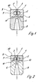
- nozzle 1 and 2 each have a nozzle for generating a high-pressure jet from a fluid medium, for example a liquid, a Liquid-solid-gas mixture or a gas, represented in its Basic structure of a nozzle body 1, one lying therein in a recess 7, made of a high-strength material nozzle disk 2 with an axial, preferably has central nozzle bore 3 and an inlet body 8 with which the nozzle body 1 in a nozzle housing, not shown, to a nozzle head is firmly clamped.
- a fluid medium for example a liquid, a Liquid-solid-gas mixture or a gas
- the inlet body 8 lies on its side facing the nozzle body 1 Side has an axially arranged feed channel 6 through which the medium below Pressure can be fed in the direction of the arrow, forming a sealing surface 11 on the end side the nozzle body 1.
- the nozzle disk lies in both of the exemplary embodiments shown 2, which preferably have a rotationally symmetrical shape, below Compressive stress on the contact surfaces of the recess 7.
- the nozzle disk 2 can of course also take other spatial forms, depending on the need.
- the nozzle disk 2 is completely removed from enclosed the nozzle body 1, that is, the nozzle disc 2 is complete so far encapsulated.
- the sealing surface 11 is towards the center area bounded by a cutout 12, which faces the front of the Nozzle disc 2 covers so far that the sealing surface 11 outside the nozzle disc 2 rests on the nozzle body 1.
- the nozzle bore 3 opens into an outlet bore 5 of the nozzle body 1.
- the nozzle disk 2 is embedded in the nozzle body 1 by casting around with the material then forming the nozzle body 1, by sintering this material or by soldering the nozzle disk 2 with the nozzle body 1.
Abstract
Description
Die vorliegende Erfindung betrifft eine Düse zur Erzeugung eines Hochdruckstrahls gemäß dem Oberbegriff des Anspruches 1.The present invention relates to a nozzle for generating a high pressure jet according to the preamble of claim 1.
Eine derartige Düse ist Bestandteil eines Düsenkopfes, der beispielsweise in der Hochdruckwasserstrahltechnik als Wasserstrahldüse Verwendung findet. Eine solche Wasserstrahldüse dient beispielsweise der Reinigung von Oberflächen, dem Abtragen von Beschichtungen, dem Aufrauen von Flächen sowie dem Schneiden und Trennen von Werkstoffen.Such a nozzle is part of a nozzle head, for example in the High pressure water jet technology is used as a water jet nozzle. Such Water jet nozzle is used for cleaning surfaces, for example Removing coatings, roughening surfaces and cutting and separating materials.
Zur Erzeugung des Hochdruckstrahles wird der von einer Pumpe in einem Volumenstrom des Mediums erzeugte Druck durch eine Querschnittsverengung innerhalb der Düse in einen Strahl, vorzugsweise einen Flüssigkeitsstrahl, mit hoher Geschwindigkeit umgewandelt. Dabei findet als Flüssigkeit üblicherweise Wasser Verwendung. Die erzeugten Drücke können bis zu 4000 bar und darüber betragen, während die Geschwindigkeit bei bis zu 900 m/s liegt. To generate the high-pressure jet, it is generated by a pump in a volume flow of the medium generated pressure by a cross-sectional narrowing within the nozzle into a jet, preferably a jet of liquid, at high speed converted. Water is usually found as the liquid Use. The pressures generated can be up to 4000 bar and above, while the speed is up to 900 m / s.
Aufgrund der sich daraus ergebenden außerordentlich hohen Beanspruchung der Düsenscheibe ist es aus der DE 94 19 809 U1 bekannt, diese aus einem Saphir herzustellen.Due to the resulting extremely high stress on the Nozzle disk is known from DE 94 19 809 U1 to produce it from a sapphire.
Für eine halbwegs akzeptable Standzeit ist es jedoch erforderlich, die Düsenscheibe sowie die Ausnehmung, in der diese einliegt, hinsichtlich der Parallelität der Kontaktflächen, der Konzentrizität und Winkligkeit sowie der Maßgenauigkeit in sehr engen Toleranzgrenzen zu bearbeiten. Abgesehen davon, dass dies nur mit einem erheblichen Fertigungsaufwand möglich ist, führen selbst die geringen Toleranzen beim Betrieb der Düse zu einer äußerst hohen Beanspruchung der Düsenscheibe, die die Standzeit sehr stark beeinflusst.For a reasonably acceptable service life, however, it is necessary to use the nozzle disc and the recess in which it lies, with regard to the parallelism of the Contact areas, the concentricity and angularity as well as the dimensional accuracy in to work with very narrow tolerance limits. Aside from the fact that this is only with one considerable manufacturing effort is possible, even the small tolerances result when the nozzle is operated, the nozzle disc is subjected to extremely high stress, which influences the service life very strongly.
Wenngleich in der DE 94 19 809 U1 nicht ausdrücklich erwähnt, wird die Düsenscheibe in der Praxis mit einem Dichtring versehen, der aus einer Buntmetall-Legierung oder einem Kunststoff gefertigt ist und der die Düsenscheibe gegenüber dem seitlichen Wandbereich der Ausnehmung des Düsenkörpers abdichtet.Although not expressly mentioned in DE 94 19 809 U1, the nozzle disc is in practice provided with a sealing ring made of a non-ferrous metal alloy or is made of a plastic and opposite the nozzle disc seals the side wall area of the recess of the nozzle body.
Allerdings ist der Dichtring nicht in der Lage, die Düsenscheibe seitlich abzustützen, wie es erforderlich wäre, um auf die Düsenscheiben einwirkende Spannungen aufzunehmen, die durch den hohen Innendruck in der Düsenbohrung entstehen. Diese nicht vorhandene radiale Unterstützung der Düsenscheibe führt häufig zu Rissen und Brüchen während des Betriebes, woraus sich gefährliche Situationen ergeben, insbesondere wenn solche Düsen in handgeführten Werkzeugen, wie beispielsweise Spritzpistolen oder dergleichen, eingesetzt werden. Durch die schlagartige Entspannung des Drucks beim Bruch der Düsenscheibe steigt die Rückstoßkraft unerwartet und unzulässig hoch an, was zu einer Gefährdung des Benutzers der Spritzpistole führen kann.However, the sealing ring is not able to support the nozzle disk laterally, as would be required to relieve stress on the nozzle disks record, which arise from the high internal pressure in the nozzle bore. This lack of radial support of the nozzle disk often leads to Cracks and breaks during operation, resulting in dangerous situations result, especially when such nozzles in hand-held tools, such as Spray guns or the like can be used. By the sudden When the pressure is released when the nozzle disk breaks, the recoil force increases unexpectedly and impermissibly high, which endangers the user the spray gun can lead.
Bei der bekannten Düse wird eine axiale Vorspannkraft über eine Druckschraube aufgebracht, die sowohl an der Düsenscheibe wie auch dem Düsenkörper anliegt. Dabei wird die Kraft über die Düsenscheibe und den Dichtring auf den Düsenkörper geleitet. In the known nozzle, an axial pretensioning force is applied via a pressure screw applied, which rests on both the nozzle disc and the nozzle body. The force is applied to the nozzle body via the nozzle disc and the sealing ring directed.
Dies setzt jedoch voraus, dass mit einem hohen Fertigungsaufwand entsprechende Höhentoleranzen der Bauteile eingehalten werden. Trotzdem kann es bei Überschreitung des Anzugsmomentes an der Druckschraube zum Bruch der spröden Düsenscheibe kommen. Dies ist relativ häufig der Fall, da viele Düsen unter rauen Betriebsbedingungen, zum Beispiel auf Baustellen zur Betonsanierung eingesetzt und montiert werden.However, this presupposes that with a high manufacturing effort Height tolerances of the components are observed. Nevertheless, it can be exceeded of the tightening torque on the pressure screw to break the brittle Nozzle disc come. This is relatively common because many of the nozzles are rough Operating conditions, for example used on construction sites for concrete renovation and be assembled.
Die genannte fehlende radiale Unterstützung der Düsenscheibe führt auch zu einer hohen Beanspruchung durch in der Strahlflüssigkeit befindliche Schmutzpartikel, die beim Aufprall auf die zugeordnete Stirnfläche der Düsenscheibe ebenfalls zu Rissen mit den geschilderten Auswirkungen führen können.The aforementioned lack of radial support for the nozzle disc also leads to one high stress caused by dirt particles in the blasting liquid, that also on impact on the assigned end face of the nozzle disc Can cause cracks with the effects described.
Der vorliegenden Erfindung liegt daher die Aufgabe zugrunde, eine Düse der gattungsgemäßen Art so weiter zu entwickeln, dass sie einfacher herstellbar ist, ihre Standzeit erhöht und die Betriebssicherheit verbessert wird.The present invention is therefore based on the object of a nozzle of the generic type Art to develop so that it is easier to manufacture your Tool life is increased and operational safety is improved.
Diese Aufgabe wird durch eine Düse gelöst, die die Merkmale des Anspruches 1 aufweist.This object is achieved by a nozzle which has the features of claim 1 having.
Eine solcher Art ausgebildete Düse weist gegenüber der bekannten Düse erhebliche Vorteile auf.A nozzle of this type has considerable properties compared to the known nozzle Advantages on.
So ist zunächst einmal zu nennen, dass die Düsenscheibe nun quasi fest eingespannt in der Ausnehmung des Düsenkörpers einliegt und zwar in allen beim Betrieb der Düse möglichen Belastungsrichtungen.First of all, it should be mentioned that the nozzle disc is now virtually firmly clamped lies in the recess of the nozzle body and in all during operation possible directions of loading of the nozzle.
Insbesondere werden wirksame Radialkräfte, die aus dem Betriebsinnendruck in der Düsenbohrung resultieren, unmittelbar auf den Düsenkörper geleitet. Dadurch wird die Düsenscheibe extrem widerstandsfähig, so dass eine plötzliche Rissbildung oder ein Bruch praktisch ausgeschlossen sind. Auch die Empfindlichkeit gegenüber Schmutzpartikeln ist erheblich reduziert.In particular, effective radial forces resulting from the internal operating pressure the nozzle bore result, directed directly to the nozzle body. Thereby the nozzle disc becomes extremely resistant, causing a sudden cracking or a break are practically impossible. Also sensitivity to Dirt particles are significantly reduced.
Nach einer vorteilhaften Weiterbildung der Erfindung sind der Düsenkörper mit der einliegenden Düsenscheibe als eine Baueinheit hergestellt und so montierbar, dass keine unmittelbaren Druckkräfte bei der Montage, beispielsweise mittels einer Druckschraube oder eines in diesem Sinne fungierenden Einlaufkörpers, auf die Düsenscheibe einwirken.According to an advantageous development of the invention, the nozzle body is included the inserted nozzle disc is manufactured as a structural unit and can be assembled in such a way that no direct pressure forces during assembly, for example by means of a Pressure screw or an inlet body acting in this sense, on the Act on the nozzle disc.
Dabei kann die Düsenscheibe im Inneren des Düsenkörpers angeordnet sein, das heißt, dass die Düsenscheibe allseitig von dem Düsenkörper umschlossen ist.The nozzle disk can be arranged inside the nozzle body means that the nozzle disk is enclosed on all sides by the nozzle body.
Aufgebrachte Spannkräfte zur Festsetzung des Düsenkörpers werden dadurch ausschließlich in den Düsenkörper geleitet.Applied clamping forces for fixing the nozzle body are exclusively passed into the nozzle body.
Dies ist gleichermaßen der Fall, wenn die Düsenscheibe in der dann stirnseitig in den Düsenkörper eingebrachten Ausnehmung einliegt, wobei der Einlaufkörper als Druckstück den Düsenkörper gegen einen Gehäuseboden verspannt und der vom Einlaufkörper ausgehende Spanndruck außerhalb der Düsenscheibe in den Düsenkörper geleitet wird.This is equally the case when the nozzle disk is in the front face the nozzle body is inserted recess, the inlet body as Pressure piece clamped the nozzle body against a housing base and that of Inlet body outgoing clamping pressure outside the nozzle disk into the nozzle body is directed.
Nach einer vorteilhaften Weiterbildung der Erfindung ist vorgesehen, dass der Düsenkörper durch Sintern oder Gießen hergestellt wird, wobei die Düsenscheibe zuvor eingebracht wird, so dass sie von dem Werkstoff des Düsenkörpers nach dem Gießen oder Sintern vollständig umschlossen ist.According to an advantageous development of the invention, it is provided that the nozzle body is produced by sintering or casting, with the nozzle disc beforehand is introduced so that it depends on the material of the nozzle body Pouring or sintering is completely enclosed.
Hierdurch kann auf eine besondere Bearbeitungsgenauigkeit der Düsenscheibe verzichtet werden, was naturgemäß mit einer Kostenersparnis verbunden ist.As a result, a special machining accuracy of the nozzle disk can be dispensed with become what is naturally associated with cost savings.
Der Düsenkörper-Werkstoff, in den die Düsenscheibe zunächst ohne Düsenbohrung eingebettet ist, ist vorzugsweise korrosionsbeständig und hochfest.The material of the nozzle body, in which the nozzle disc initially has no nozzle bore is preferably corrosion-resistant and high-strength.
Durch den Sinterprozess bzw. das Gießen werden auf die Kontaktflächen der Düsenscheibe hohe, bleibende Druckspannungen aufgebracht, die für den Betrieb der Düse die genannten Vorteile mit sich bringen.Through the sintering process or the casting are on the contact surfaces of the nozzle disc high, permanent compressive stresses applied for the operation of the Nozzle bring the advantages mentioned.
Nach Beendigung des Sinterns bzw. des Gießens werden die Außen- bzw. Dichtflächen des Dichtkörpers hergestellt, sowie eine Austritts- und ggf. eine Eintrittsbohrung und die Düsenbohrung eingebracht. Hierdurch wird eine hohe Konzentrizität erreicht, die zu einer Optimierung des aus der Düse austretenden Mediumstrahles führt.After sintering or casting has ended, the outer or sealing surfaces of the sealing body, as well as an outlet and possibly an inlet bore and introduced the nozzle bore. This makes it highly concentric reached, which optimizes the medium jet emerging from the nozzle leads.
Da ein betriebsbedingter Bruch der Düsenscheibe praktisch ausgeschlossen ist, erhöht sich die Betriebssicherheit für den Benutzer gegenüber der bekannten Düse. Darüber hinaus ergibt sich auch eine Erhöhung der Standzeit, die dadurch noch zusätzlich gesteigert wird, dass der Düsenkörper mit der eingelagerten Düsenscheibe sowohl in Längs- wie auch in Querachsrichtung spiegelsymmetrisch ausgebildet ist. Dies eröffnet die Möglichkeit, den Düsenkörper zu wenden, wenn der Eingangsbereich der Düsenbohrung betriebsbedingt abgenutzt sein sollte. In diesem Fall wird der Düsenkörper mit der eingeschlossenen Düsenscheibe lediglich um 180° Grad gedreht, so dass dann die vorherige Ausgangsseite der Düsenbohrung nun die Eingangsseite bildet.Since an operational breakage of the nozzle disc is practically impossible, increased operational safety for the user compared to the known nozzle. In addition, there is an increase in tool life, which is additional is increased that the nozzle body with the embedded nozzle disc mirror-symmetrical in both the longitudinal and transverse axis directions is. This opens up the possibility of turning the nozzle body when the entrance area the nozzle bore should be worn due to operational reasons. In this Case, the nozzle body with the included nozzle disc is only around Rotated 180 degrees so that then the previous exit side of the nozzle bore now forms the entry page.
Die Düsenscheibe kann aus einem keramischen Hartstoff bestehen, vorzugsweise einem Saphir, Rubin, polykristallinem Diamant oder einer Mischkeramik.The nozzle disk can consist of a ceramic hard material, preferably a sapphire, ruby, polycrystalline diamond or a mixed ceramic.
Neben der genannten Möglichkeit, die Düsenscheibe durch Gießen oder Sintern des Düsenkörpers einzubetten, besteht auch die Möglichkeit, sie mit dem Düsenkörper zu verlöten, vorzugsweise durch Hartlöten.In addition to the possibility mentioned, the nozzle disk by casting or sintering embedding the nozzle body, it is also possible to use the nozzle body to be soldered, preferably by brazing.
In jedem Fall erlaubt die robuste Bauweise der Düse auch die Einbringung von Flachstrahlgeometrien der Düsenbohrung, die dann einen von der Kreisform abweichenden Querschnitt aufweisen kann, beispielsweise elliptisch oder rechteckig. Insofern ergibt sich durch die Erfindung ein erweiterter Einsatzbereich.In any case, the robust design of the nozzle also allows the introduction of Flat jet geometries of the nozzle bore, which then deviate from the circular shape Can have cross-section, for example elliptical or rectangular. In this respect, the invention results in an expanded area of application.
Zur Erhöhung der Standzeit kann neben der genannten Wendemöglichkeit des Düsenkörpers, die Düsenbohrung nachgearbeitet werden, insbesondere im Bereich der Eintrittskante, so dass sich insgesamt eine auch in betriebswirtschaftlicher Hinsicht nennenswerte Verbesserung ergibt.To increase the service life, in addition to the above-mentioned possibility of turning the nozzle body, the nozzle bore are reworked, especially in the area of Leading edge, so that overall one is also in business terms significant improvement.
Weitere vorteilhafte Ausbildungen der Erfindung sind in den Unteransprüchen gekennzeichnet. Further advantageous developments of the invention are characterized in the subclaims.
Ausführungsbeispiele der Erfindung werden nachfolgend anhand der beigefügten Zeichnungen beschrieben.Embodiments of the invention are described below with reference to the accompanying Described drawings.
Es zeigen:
- Figuren 1 und 2
- jeweils eine erfindungsgemäße Düse in einem Längsschnitt.
- Figures 1 and 2
- each a nozzle according to the invention in a longitudinal section.
In den Figuren 1 und 2 ist jeweils eine Düse zur Erzeugung eines Hochdruckstrahls
aus einem strömungsfähigen Medium, beispielsweise einer Flüssigkeit, einem
Flüssigkeit-Feststoff-Gas-Gemisch oder einem Gas, dargestellt, die in ihrem
Grundaufbau einen Düsenkörper 1, eine darin in einer Ausnehmung 7 einliegende,
aus einem hochfesten Werkstoff bestehende Düsenscheibe 2 mit einer axialen, vorzugsweise
zentrischen Düsenbohrung 3 sowie einen Einlaufkörper 8 aufweist, mit
dem der Düsenkörper 1 in einem nicht dargestellten Düsengehäuse zu einem Düsenkopf
fest verspannbar ist.1 and 2 each have a nozzle for generating a high-pressure jet
from a fluid medium, for example a liquid, a
Liquid-solid-gas mixture or a gas, represented in its
Basic structure of a nozzle body 1, one lying therein in a
Dabei liegt der Einlaufkörper 8, der auf seiner dem Düsenkörper 1 zugewandten
Seite einen axial angeordneten Zuführkanal 6 aufweist, durch den das Medium unter
Druck in Pfeilrichtung einspeisbar ist, stimseitig eine Dichtfläche 11 bildend, an
dem Düsenkörper 1 an.In this case, the
Erfindungsgemäß liegen bei beiden gezeigten Ausführungsbeispielen die Düsenscheibe
2, die vorzugsweise eine rotationssymmetrische Form aufweisen, unter
Druckspannung an den Kontaktflächen der Ausnehmung 7 an. Neben einer zylindrischen
kann die Düsenscheibe 2 selbstverständlich auch andere Raumformen einnehmen,
je nach Bedarfsfall.According to the invention, the nozzle disk lies in both of the exemplary embodiments shown
2, which preferably have a rotationally symmetrical shape, below
Compressive stress on the contact surfaces of the
Bei dem in der Figur 1 gezeigten Beispiel wird die Düsenscheibe 2 vollständig von dem Düsenkörper 1 umschlossen, das heißt, die Düsenscheibe 2 ist insoweit vollständig eingekapselt.In the example shown in FIG. 1, the nozzle disk 2 is completely removed from enclosed the nozzle body 1, that is, the nozzle disc 2 is complete so far encapsulated.
Demgegenüber ist sie bei der in der Figur 2 gezeigten Ausführung lediglich seitlich
und auf der dem Einlaufkörper 8 gegenüberliegenden Stirnseite unter Druckspannung
an der Ausnehmung anliegend. Hierbei ist die Dichtfläche 11 zum Mittenbereich
hin begrenzt durch einen Freischnitt 12, der die zugewandte Stirnseite der
Düsenscheibe 2 soweit überdeckt, dass die Dichtfläche 11 außerhalb der Düsenscheibe
2 am Düsenkörper 1 anliegt.In contrast, in the embodiment shown in FIG. 2, it is only on the side
and on the end face opposite the
In beiden Fällen mündet die Düsenbohrung 3 in eine Austrittsbohrung 5 des Düsenkörpers
1.In both cases, the
Während das durch den Zuführkanal 6 strömende Medium bei der in der Figur 1
gezeigten Düse unmittelbar in eine Eintrittsbohrung 6 des Düsenkörpers 1, an die
sich die Düsenbohrung 3 anschließt, geführt wird, wird das Medium bei der Düse
nach Figur 2 der Düsenbohrung 3 über den Freischnitt 12 zugeführt, der sich konzentrisch
an den Zuführkanal 6 anschließt.While the medium flowing through the
Wie bereits geschildert, erfolgt die Einbettung der Düsenscheibe 2 in den Düsenkörper 1 durch Umgießen mit dem dann den Düsenkörper 1 bildenden Werkstoff, durch Sinterung dieses Werkstoffes oder durch Verlöten der Düsenscheibe 2 mit dem Düsenkörper 1.As already described, the nozzle disk 2 is embedded in the nozzle body 1 by casting around with the material then forming the nozzle body 1, by sintering this material or by soldering the nozzle disk 2 with the nozzle body 1.
Eine weitere Bearbeitung dieser Baueinheit zur Einbringung der Düsenbohrung 3,
der Eintrittsbohrung 4, der Austrittsbohrung 5 sowie zur Herstellung einer Außenfläche
9 und einer Dichtfläche 10 des Düsenkörpers 1, die dem Einlaufkörper 8 gegenüberliegend
die Stirnfläche bildet, erfolgt anschließend, ohne daß besonders
enge Toleranzen beachtet werden müssen. A further processing of this assembly for the introduction of the nozzle bore 3,
the inlet bore 4, the outlet bore 5 and for producing an outer surface
9 and a sealing surface 10 of the nozzle body 1, which is opposite the
- 11
- Düsenkörpernozzle body
- 22
- Düsenscheibenozzle disk
- 33
- Düsenbohrungnozzle bore
- 44
- Eintrittsbohrunginlet bore
- 55
- Austrittsbohrungoutlet bore
- 66
- Zuführkanalfeed
- 77
- Ausnehmungrecess
- 88th
- Einlaufkörperinlet body
- 99
- Außenflächeouter surface
- 1010
- Dichtflächesealing surface
- 1111
- Dichtflächesealing surface
- 1212
- FreischnittClear cut
Claims (11)
Applications Claiming Priority (2)
| Application Number | Priority Date | Filing Date | Title |
|---|---|---|---|
| DE10248357A DE10248357A1 (en) | 2002-10-17 | 2002-10-17 | Nozzle for generating a high pressure jet |
| DE10248357 | 2002-10-17 |
Publications (2)
| Publication Number | Publication Date |
|---|---|
| EP1410846A1 true EP1410846A1 (en) | 2004-04-21 |
| EP1410846B1 EP1410846B1 (en) | 2010-03-31 |
Family
ID=32038730
Family Applications (1)
| Application Number | Title | Priority Date | Filing Date |
|---|---|---|---|
| EP03021417A Expired - Lifetime EP1410846B1 (en) | 2002-10-17 | 2003-09-23 | High pressure jet nozzle |
Country Status (7)
| Country | Link |
|---|---|
| US (1) | US7243865B2 (en) |
| EP (1) | EP1410846B1 (en) |
| JP (1) | JP2004148310A (en) |
| AT (1) | ATE462499T1 (en) |
| AU (1) | AU2003254727B2 (en) |
| DE (2) | DE10248357A1 (en) |
| ES (1) | ES2342267T3 (en) |
Cited By (1)
| Publication number | Priority date | Publication date | Assignee | Title |
|---|---|---|---|---|
| CN106733250A (en) * | 2016-11-23 | 2017-05-31 | 河池学院 | A kind of shower nozzle of spray robot |
Families Citing this family (11)
| Publication number | Priority date | Publication date | Assignee | Title |
|---|---|---|---|---|
| US7237308B2 (en) * | 2004-06-10 | 2007-07-03 | North Carolina State University | Composite hydroentangling nozzle strip and method for producing nonwoven fabrics therewith |
| GB0522444D0 (en) * | 2005-11-03 | 2005-12-14 | Miller Donald S | Cutting heads |
| JP2008253891A (en) * | 2007-04-03 | 2008-10-23 | Takuma Co Ltd | Nozzle device |
| US9168569B2 (en) | 2007-10-22 | 2015-10-27 | Stokely-Van Camp, Inc. | Container rinsing system and method |
| US8147616B2 (en) * | 2007-10-22 | 2012-04-03 | Stokely-Van Camp, Inc. | Container rinsing system and method |
| KR101337713B1 (en) * | 2012-12-20 | 2013-12-06 | 주식회사 현대케피코 | Vehicular gdi injector with valve seat body for fuel atomization |
| WO2014147593A1 (en) * | 2013-03-21 | 2014-09-25 | Flsmidth A/S | A nozzle |
| RU2641277C1 (en) | 2016-12-26 | 2018-01-16 | Михаил Николаевич Болдырев | Device and method for hydrodynamic cleaning of surfaces based on micro-hydropercussion effect |
| CN111491681A (en) * | 2017-11-27 | 2020-08-04 | 索芙特海尔公司 | Nozzle holder for an inhalation device |
| US20220105525A1 (en) * | 2020-10-02 | 2022-04-07 | Diamond Technology Innovations | Fan jet nozzle assembly |
| JP2022156158A (en) * | 2021-03-31 | 2022-10-14 | セイコーエプソン株式会社 | Liquid jet nozzle and liquid jet device |
Citations (7)
| Publication number | Priority date | Publication date | Assignee | Title |
|---|---|---|---|---|
| CH567907A5 (en) * | 1973-02-22 | 1975-10-15 | Bendix Corp | Textile fluid jet cutter - nozzle geometry permitting formation of long lasting coherent cutting jet |
| US4349947A (en) * | 1980-09-29 | 1982-09-21 | Nordson Corporation | Method for manufacturing an airless spray nozzle |
| US5033681A (en) * | 1990-05-10 | 1991-07-23 | Ingersoll-Rand Company | Ion implantation for fluid nozzle |
| DE9419809U1 (en) | 1994-12-10 | 1995-01-26 | Woma Maasberg Co Gmbh W | Nozzle insert for a nozzle head of a high-pressure water jet device |
| US5848753A (en) * | 1997-01-27 | 1998-12-15 | Ingersoll-Rand Company | Waterjet orifice assembly |
| US5893520A (en) * | 1995-06-07 | 1999-04-13 | Elkas; Michael V. | Ultra-dry fog box |
| WO2001044553A1 (en) * | 1999-12-17 | 2001-06-21 | Rieter Perfojet | Device for treating sheet-like material using pressurized water jets |
Family Cites Families (9)
| Publication number | Priority date | Publication date | Assignee | Title |
|---|---|---|---|---|
| US3447756A (en) * | 1966-09-02 | 1969-06-03 | Robert C Lawrence Jr | Spray nozzle |
| US4258885A (en) * | 1979-03-23 | 1981-03-31 | Legeza Thomas B | Nozzle tip and method of manufacture |
| DE19536903C2 (en) * | 1995-10-04 | 1998-09-10 | Boehringer Ingelheim Int | Device for holding a fluidic component |
| US5730358A (en) * | 1995-12-22 | 1998-03-24 | Flow International Corporation | Tunable ultrahigh-pressure nozzle |
| US5730338A (en) * | 1996-09-23 | 1998-03-24 | Chrysler Corporation | Tire mounting bracket for the elimination of the spare tire obstruction |
| DE19849814A1 (en) * | 1998-10-29 | 2000-05-04 | Saechsische Werkzeug Und Sonde | Nozzle to form jet of water in water jet cutting heads has wear-resistant nozzle inserts fitted one behind other in point of body's central bore and forming nozzle segments of different shapes which form jet pipe |
| AU1379500A (en) * | 1999-02-12 | 2000-08-29 | Alfred Karcher Gmbh & Co. Kg | Jet tube for high-pressure cleaning devices |
| US6817550B2 (en) * | 2001-07-06 | 2004-11-16 | Diamicron, Inc. | Nozzles, and components thereof and methods for making the same |
| US6722588B1 (en) * | 2003-04-09 | 2004-04-20 | Atomizing Systems, Inc. | Fog nozzle with jeweled orifice |
-
2002
- 2002-10-17 DE DE10248357A patent/DE10248357A1/en not_active Ceased
-
2003
- 2003-09-23 EP EP03021417A patent/EP1410846B1/en not_active Expired - Lifetime
- 2003-09-23 AT AT03021417T patent/ATE462499T1/en not_active IP Right Cessation
- 2003-09-23 ES ES03021417T patent/ES2342267T3/en not_active Expired - Lifetime
- 2003-09-23 DE DE50312563T patent/DE50312563D1/en not_active Expired - Lifetime
- 2003-10-14 US US10/683,284 patent/US7243865B2/en not_active Expired - Fee Related
- 2003-10-15 AU AU2003254727A patent/AU2003254727B2/en not_active Ceased
- 2003-10-17 JP JP2003358055A patent/JP2004148310A/en active Pending
Patent Citations (7)
| Publication number | Priority date | Publication date | Assignee | Title |
|---|---|---|---|---|
| CH567907A5 (en) * | 1973-02-22 | 1975-10-15 | Bendix Corp | Textile fluid jet cutter - nozzle geometry permitting formation of long lasting coherent cutting jet |
| US4349947A (en) * | 1980-09-29 | 1982-09-21 | Nordson Corporation | Method for manufacturing an airless spray nozzle |
| US5033681A (en) * | 1990-05-10 | 1991-07-23 | Ingersoll-Rand Company | Ion implantation for fluid nozzle |
| DE9419809U1 (en) | 1994-12-10 | 1995-01-26 | Woma Maasberg Co Gmbh W | Nozzle insert for a nozzle head of a high-pressure water jet device |
| US5893520A (en) * | 1995-06-07 | 1999-04-13 | Elkas; Michael V. | Ultra-dry fog box |
| US5848753A (en) * | 1997-01-27 | 1998-12-15 | Ingersoll-Rand Company | Waterjet orifice assembly |
| WO2001044553A1 (en) * | 1999-12-17 | 2001-06-21 | Rieter Perfojet | Device for treating sheet-like material using pressurized water jets |
Cited By (1)
| Publication number | Priority date | Publication date | Assignee | Title |
|---|---|---|---|---|
| CN106733250A (en) * | 2016-11-23 | 2017-05-31 | 河池学院 | A kind of shower nozzle of spray robot |
Also Published As
| Publication number | Publication date |
|---|---|
| US20040164173A1 (en) | 2004-08-26 |
| ES2342267T3 (en) | 2010-07-05 |
| US7243865B2 (en) | 2007-07-17 |
| DE50312563D1 (en) | 2010-05-12 |
| ATE462499T1 (en) | 2010-04-15 |
| AU2003254727A1 (en) | 2004-05-13 |
| JP2004148310A (en) | 2004-05-27 |
| DE10248357A1 (en) | 2004-05-06 |
| EP1410846B1 (en) | 2010-03-31 |
| AU2003254727B2 (en) | 2008-03-06 |
Similar Documents
| Publication | Publication Date | Title |
|---|---|---|
| DE2619539A1 (en) | SPRAY NOZZLE SILENCER | |
| EP1410846A1 (en) | High pressure jet nozzle | |
| DE102010004526B4 (en) | cutting tool | |
| WO2006125690A1 (en) | Outlet connection for a high-pressure pump | |
| DE2234669B2 (en) | Nozzle assembly | |
| EP2573440A2 (en) | Connection assembly | |
| EP3331658A1 (en) | Replaceable cutting head, tool shank, and shank-mounted tool | |
| WO2010086330A1 (en) | Geometry for increasing the strength in bore intersections in the high-pressure region | |
| EP2613913B1 (en) | Lance having a discharge nozzle, for deburring and/or cleaning workpieces | |
| EP1509308B1 (en) | Device for filtering fluids that are conveyed under a high pressure | |
| DE19831743B4 (en) | Device for processing workpieces | |
| DE3935753C2 (en) | ||
| EP3143274B1 (en) | Fuel supply arrangement for a fuel injector and fuel injector | |
| DE10145062B4 (en) | beam head | |
| EP0894194B1 (en) | Injection device | |
| EP0108944B1 (en) | Positive displacement member of a piston pump | |
| EP1837123B1 (en) | Tool for machining surfaces and method for producing such a tool | |
| DE19855795B4 (en) | Cutting ring fitting for pressure medium piping | |
| DE19726421B4 (en) | The diamond saw | |
| DE10230170B3 (en) | Method and device for hydro-erosively rounding an edge of a component | |
| DE2523159A1 (en) | Prestressed die for upsetting steel blanks - using compressive stress in both axial and radial directions to prevent die cracking (BR071276) | |
| DD256899A1 (en) | SELF-SAFE CONNECTING ELEMENT | |
| DE1540140C3 (en) | Arrangement with a tension clamp for cementless fastening of ceramic insulators | |
| DE4311280C2 (en) | Process for producing a cutting ring and cutting ring | |
| DE102016113977A1 (en) | Nozzle head for a lance, lance and method of making a nozzle head for a lance |
Legal Events
| Date | Code | Title | Description |
|---|---|---|---|
| PUAI | Public reference made under article 153(3) epc to a published international application that has entered the european phase |
Free format text: ORIGINAL CODE: 0009012 |
|
| AK | Designated contracting states |
Kind code of ref document: A1 Designated state(s): AT BE BG CH CY CZ DE DK EE ES FI FR GB GR HU IE IT LI LU MC NL PT RO SE SI SK TR |
|
| AX | Request for extension of the european patent |
Extension state: AL LT LV MK |
|
| 17P | Request for examination filed |
Effective date: 20040709 |
|
| AKX | Designation fees paid |
Designated state(s): AT BE BG CH CY CZ DE DK EE ES FI FR GB GR HU IE IT LI LU MC NL PT RO SE SI SK TR |
|
| 17Q | First examination report despatched |
Effective date: 20041216 |
|
| GRAP | Despatch of communication of intention to grant a patent |
Free format text: ORIGINAL CODE: EPIDOSNIGR1 |
|
| GRAS | Grant fee paid |
Free format text: ORIGINAL CODE: EPIDOSNIGR3 |
|
| GRAA | (expected) grant |
Free format text: ORIGINAL CODE: 0009210 |
|
| AK | Designated contracting states |
Kind code of ref document: B1 Designated state(s): AT BE BG CH CY CZ DE DK EE ES FI FR GB GR HU IE IT LI LU MC NL PT RO SE SI SK TR |
|
| REG | Reference to a national code |
Ref country code: GB Ref legal event code: FG4D Free format text: NOT ENGLISH Ref country code: CH Ref legal event code: EP |
|
| REG | Reference to a national code |
Ref country code: IE Ref legal event code: FG4D |
|
| REF | Corresponds to: |
Ref document number: 50312563 Country of ref document: DE Date of ref document: 20100512 Kind code of ref document: P |
|
| REG | Reference to a national code |
Ref country code: CH Ref legal event code: NV Representative=s name: ISLER & PEDRAZZINI AG |
|
| REG | Reference to a national code |
Ref country code: NL Ref legal event code: T3 |
|
| REG | Reference to a national code |
Ref country code: ES Ref legal event code: FG2A Ref document number: 2342267 Country of ref document: ES Kind code of ref document: T3 |
|
| PG25 | Lapsed in a contracting state [announced via postgrant information from national office to epo] |
Ref country code: FI Free format text: LAPSE BECAUSE OF FAILURE TO SUBMIT A TRANSLATION OF THE DESCRIPTION OR TO PAY THE FEE WITHIN THE PRESCRIBED TIME-LIMIT Effective date: 20100331 Ref country code: SI Free format text: LAPSE BECAUSE OF FAILURE TO SUBMIT A TRANSLATION OF THE DESCRIPTION OR TO PAY THE FEE WITHIN THE PRESCRIBED TIME-LIMIT Effective date: 20100331 |
|
| REG | Reference to a national code |
Ref country code: IE Ref legal event code: FD4D |
|
| PG25 | Lapsed in a contracting state [announced via postgrant information from national office to epo] |
Ref country code: SE Free format text: LAPSE BECAUSE OF FAILURE TO SUBMIT A TRANSLATION OF THE DESCRIPTION OR TO PAY THE FEE WITHIN THE PRESCRIBED TIME-LIMIT Effective date: 20100331 Ref country code: RO Free format text: LAPSE BECAUSE OF FAILURE TO SUBMIT A TRANSLATION OF THE DESCRIPTION OR TO PAY THE FEE WITHIN THE PRESCRIBED TIME-LIMIT Effective date: 20100331 Ref country code: CY Free format text: LAPSE BECAUSE OF FAILURE TO SUBMIT A TRANSLATION OF THE DESCRIPTION OR TO PAY THE FEE WITHIN THE PRESCRIBED TIME-LIMIT Effective date: 20100331 Ref country code: EE Free format text: LAPSE BECAUSE OF FAILURE TO SUBMIT A TRANSLATION OF THE DESCRIPTION OR TO PAY THE FEE WITHIN THE PRESCRIBED TIME-LIMIT Effective date: 20100331 |
|
| PG25 | Lapsed in a contracting state [announced via postgrant information from national office to epo] |
Ref country code: CZ Free format text: LAPSE BECAUSE OF FAILURE TO SUBMIT A TRANSLATION OF THE DESCRIPTION OR TO PAY THE FEE WITHIN THE PRESCRIBED TIME-LIMIT Effective date: 20100331 Ref country code: SK Free format text: LAPSE BECAUSE OF FAILURE TO SUBMIT A TRANSLATION OF THE DESCRIPTION OR TO PAY THE FEE WITHIN THE PRESCRIBED TIME-LIMIT Effective date: 20100331 |
|
| PG25 | Lapsed in a contracting state [announced via postgrant information from national office to epo] |
Ref country code: DK Free format text: LAPSE BECAUSE OF FAILURE TO SUBMIT A TRANSLATION OF THE DESCRIPTION OR TO PAY THE FEE WITHIN THE PRESCRIBED TIME-LIMIT Effective date: 20100331 Ref country code: PT Free format text: LAPSE BECAUSE OF FAILURE TO SUBMIT A TRANSLATION OF THE DESCRIPTION OR TO PAY THE FEE WITHIN THE PRESCRIBED TIME-LIMIT Effective date: 20100802 Ref country code: IE Free format text: LAPSE BECAUSE OF FAILURE TO SUBMIT A TRANSLATION OF THE DESCRIPTION OR TO PAY THE FEE WITHIN THE PRESCRIBED TIME-LIMIT Effective date: 20100331 |
|
| PLBE | No opposition filed within time limit |
Free format text: ORIGINAL CODE: 0009261 |
|
| STAA | Information on the status of an ep patent application or granted ep patent |
Free format text: STATUS: NO OPPOSITION FILED WITHIN TIME LIMIT |
|
| 26N | No opposition filed |
Effective date: 20110104 |
|
| BERE | Be: lapsed |
Owner name: HAMMELMANN MASCHINENFABRIK G.M.B.H. Effective date: 20100930 |
|
| PG25 | Lapsed in a contracting state [announced via postgrant information from national office to epo] |
Ref country code: MC Free format text: LAPSE BECAUSE OF NON-PAYMENT OF DUE FEES Effective date: 20100930 |
|
| PG25 | Lapsed in a contracting state [announced via postgrant information from national office to epo] |
Ref country code: BE Free format text: LAPSE BECAUSE OF NON-PAYMENT OF DUE FEES Effective date: 20100930 |
|
| PG25 | Lapsed in a contracting state [announced via postgrant information from national office to epo] |
Ref country code: AT Free format text: LAPSE BECAUSE OF NON-PAYMENT OF DUE FEES Effective date: 20100923 |
|
| PG25 | Lapsed in a contracting state [announced via postgrant information from national office to epo] |
Ref country code: HU Free format text: LAPSE BECAUSE OF FAILURE TO SUBMIT A TRANSLATION OF THE DESCRIPTION OR TO PAY THE FEE WITHIN THE PRESCRIBED TIME-LIMIT Effective date: 20101001 Ref country code: BG Free format text: LAPSE BECAUSE OF FAILURE TO SUBMIT A TRANSLATION OF THE DESCRIPTION OR TO PAY THE FEE WITHIN THE PRESCRIBED TIME-LIMIT Effective date: 20100331 Ref country code: LU Free format text: LAPSE BECAUSE OF NON-PAYMENT OF DUE FEES Effective date: 20100923 |
|
| PG25 | Lapsed in a contracting state [announced via postgrant information from national office to epo] |
Ref country code: TR Free format text: LAPSE BECAUSE OF FAILURE TO SUBMIT A TRANSLATION OF THE DESCRIPTION OR TO PAY THE FEE WITHIN THE PRESCRIBED TIME-LIMIT Effective date: 20100331 |
|
| PG25 | Lapsed in a contracting state [announced via postgrant information from national office to epo] |
Ref country code: BG Free format text: LAPSE BECAUSE OF FAILURE TO SUBMIT A TRANSLATION OF THE DESCRIPTION OR TO PAY THE FEE WITHIN THE PRESCRIBED TIME-LIMIT Effective date: 20100630 |
|
| PG25 | Lapsed in a contracting state [announced via postgrant information from national office to epo] |
Ref country code: GR Free format text: LAPSE BECAUSE OF FAILURE TO SUBMIT A TRANSLATION OF THE DESCRIPTION OR TO PAY THE FEE WITHIN THE PRESCRIBED TIME-LIMIT Effective date: 20100331 |
|
| REG | Reference to a national code |
Ref country code: FR Ref legal event code: PLFP Year of fee payment: 13 |
|
| PGFP | Annual fee paid to national office [announced via postgrant information from national office to epo] |
Ref country code: GB Payment date: 20150922 Year of fee payment: 13 Ref country code: ES Payment date: 20150923 Year of fee payment: 13 Ref country code: CH Payment date: 20150922 Year of fee payment: 13 |
|
| PGFP | Annual fee paid to national office [announced via postgrant information from national office to epo] |
Ref country code: FR Payment date: 20150923 Year of fee payment: 13 |
|
| PGFP | Annual fee paid to national office [announced via postgrant information from national office to epo] |
Ref country code: IT Payment date: 20150925 Year of fee payment: 13 |
|
| PGFP | Annual fee paid to national office [announced via postgrant information from national office to epo] |
Ref country code: NL Payment date: 20150923 Year of fee payment: 13 |
|
| PGFP | Annual fee paid to national office [announced via postgrant information from national office to epo] |
Ref country code: DE Payment date: 20160930 Year of fee payment: 14 |
|
| REG | Reference to a national code |
Ref country code: CH Ref legal event code: PL |
|
| REG | Reference to a national code |
Ref country code: NL Ref legal event code: MM Effective date: 20161001 |
|
| GBPC | Gb: european patent ceased through non-payment of renewal fee |
Effective date: 20160923 |
|
| PG25 | Lapsed in a contracting state [announced via postgrant information from national office to epo] |
Ref country code: NL Free format text: LAPSE BECAUSE OF NON-PAYMENT OF DUE FEES Effective date: 20161001 |
|
| REG | Reference to a national code |
Ref country code: FR Ref legal event code: ST Effective date: 20170531 |
|
| PG25 | Lapsed in a contracting state [announced via postgrant information from national office to epo] |
Ref country code: GB Free format text: LAPSE BECAUSE OF NON-PAYMENT OF DUE FEES Effective date: 20160923 Ref country code: CH Free format text: LAPSE BECAUSE OF NON-PAYMENT OF DUE FEES Effective date: 20160930 Ref country code: FR Free format text: LAPSE BECAUSE OF NON-PAYMENT OF DUE FEES Effective date: 20160930 Ref country code: LI Free format text: LAPSE BECAUSE OF NON-PAYMENT OF DUE FEES Effective date: 20160930 |
|
| PG25 | Lapsed in a contracting state [announced via postgrant information from national office to epo] |
Ref country code: IT Free format text: LAPSE BECAUSE OF NON-PAYMENT OF DUE FEES Effective date: 20160923 |
|
| REG | Reference to a national code |
Ref country code: DE Ref legal event code: R119 Ref document number: 50312563 Country of ref document: DE |
|
| PG25 | Lapsed in a contracting state [announced via postgrant information from national office to epo] |
Ref country code: ES Free format text: LAPSE BECAUSE OF NON-PAYMENT OF DUE FEES Effective date: 20160924 |
|
| PG25 | Lapsed in a contracting state [announced via postgrant information from national office to epo] |
Ref country code: DE Free format text: LAPSE BECAUSE OF NON-PAYMENT OF DUE FEES Effective date: 20180404 |
|
| REG | Reference to a national code |
Ref country code: ES Ref legal event code: FD2A Effective date: 20181126 |