EP1413436A2 - Apparatus and method for electrical interconnection for inkjet devices - Google Patents
Apparatus and method for electrical interconnection for inkjet devices Download PDFInfo
- Publication number
- EP1413436A2 EP1413436A2 EP20030010415 EP03010415A EP1413436A2 EP 1413436 A2 EP1413436 A2 EP 1413436A2 EP 20030010415 EP20030010415 EP 20030010415 EP 03010415 A EP03010415 A EP 03010415A EP 1413436 A2 EP1413436 A2 EP 1413436A2
- Authority
- EP
- European Patent Office
- Prior art keywords
- contact surfaces
- stall
- layer
- electrical contact
- electrical
- Prior art date
- Legal status (The legal status is an assumption and is not a legal conclusion. Google has not performed a legal analysis and makes no representation as to the accuracy of the status listed.)
- Granted
Links
- 238000000034 method Methods 0.000 title claims description 5
- 239000004020 conductor Substances 0.000 claims abstract description 7
- PCHJSUWPFVWCPO-UHFFFAOYSA-N gold Chemical compound [Au] PCHJSUWPFVWCPO-UHFFFAOYSA-N 0.000 claims description 10
- 229910052737 gold Inorganic materials 0.000 claims description 10
- 239000010931 gold Substances 0.000 claims description 10
- KDLHZDBZIXYQEI-UHFFFAOYSA-N Palladium Chemical compound [Pd] KDLHZDBZIXYQEI-UHFFFAOYSA-N 0.000 claims description 8
- 239000000463 material Substances 0.000 claims description 4
- 229910052763 palladium Inorganic materials 0.000 claims description 4
- 229920002595 Dielectric elastomer Polymers 0.000 claims 3
- 238000011109 contamination Methods 0.000 claims 1
- 230000007613 environmental effect Effects 0.000 claims 1
- 238000002955 isolation Methods 0.000 claims 1
- 239000000725 suspension Substances 0.000 claims 1
- 239000010410 layer Substances 0.000 description 41
- 229920001971 elastomer Polymers 0.000 description 14
- 239000000806 elastomer Substances 0.000 description 14
- 230000006835 compression Effects 0.000 description 5
- 238000007906 compression Methods 0.000 description 5
- PXHVJJICTQNCMI-UHFFFAOYSA-N Nickel Chemical compound [Ni] PXHVJJICTQNCMI-UHFFFAOYSA-N 0.000 description 4
- 239000000758 substrate Substances 0.000 description 4
- 238000005260 corrosion Methods 0.000 description 3
- 230000007797 corrosion Effects 0.000 description 3
- 238000003780 insertion Methods 0.000 description 3
- 230000037431 insertion Effects 0.000 description 3
- 239000011159 matrix material Substances 0.000 description 3
- RYGMFSIKBFXOCR-UHFFFAOYSA-N Copper Chemical compound [Cu] RYGMFSIKBFXOCR-UHFFFAOYSA-N 0.000 description 2
- 229910052802 copper Inorganic materials 0.000 description 2
- 239000010949 copper Substances 0.000 description 2
- 229910052759 nickel Inorganic materials 0.000 description 2
- 230000008569 process Effects 0.000 description 2
- 239000000853 adhesive Substances 0.000 description 1
- 230000001070 adhesive effect Effects 0.000 description 1
- 239000003989 dielectric material Substances 0.000 description 1
- 238000009713 electroplating Methods 0.000 description 1
- 229920006351 engineering plastic Polymers 0.000 description 1
- 238000007654 immersion Methods 0.000 description 1
- 239000012212 insulator Substances 0.000 description 1
- 230000003993 interaction Effects 0.000 description 1
- 238000004519 manufacturing process Methods 0.000 description 1
- 230000007246 mechanism Effects 0.000 description 1
- 229910052751 metal Inorganic materials 0.000 description 1
- 239000002184 metal Substances 0.000 description 1
- 238000012986 modification Methods 0.000 description 1
- 230000004048 modification Effects 0.000 description 1
- 239000002245 particle Substances 0.000 description 1
- 229920000642 polymer Polymers 0.000 description 1
- 230000001681 protective effect Effects 0.000 description 1
- 239000011241 protective layer Substances 0.000 description 1
- 230000004044 response Effects 0.000 description 1
- 229920002379 silicone rubber Polymers 0.000 description 1
- 239000007921 spray Substances 0.000 description 1
Images


Classifications
-
- B—PERFORMING OPERATIONS; TRANSPORTING
- B41—PRINTING; LINING MACHINES; TYPEWRITERS; STAMPS
- B41J—TYPEWRITERS; SELECTIVE PRINTING MECHANISMS, i.e. MECHANISMS PRINTING OTHERWISE THAN FROM A FORME; CORRECTION OF TYPOGRAPHICAL ERRORS
- B41J2/00—Typewriters or selective printing mechanisms characterised by the printing or marking process for which they are designed
- B41J2/005—Typewriters or selective printing mechanisms characterised by the printing or marking process for which they are designed characterised by bringing liquid or particles selectively into contact with a printing material
- B41J2/01—Ink jet
- B41J2/17—Ink jet characterised by ink handling
- B41J2/175—Ink supply systems ; Circuit parts therefor
- B41J2/17503—Ink cartridges
- B41J2/1752—Mounting within the printer
-
- B—PERFORMING OPERATIONS; TRANSPORTING
- B41—PRINTING; LINING MACHINES; TYPEWRITERS; STAMPS
- B41J—TYPEWRITERS; SELECTIVE PRINTING MECHANISMS, i.e. MECHANISMS PRINTING OTHERWISE THAN FROM A FORME; CORRECTION OF TYPOGRAPHICAL ERRORS
- B41J2/00—Typewriters or selective printing mechanisms characterised by the printing or marking process for which they are designed
- B41J2/005—Typewriters or selective printing mechanisms characterised by the printing or marking process for which they are designed characterised by bringing liquid or particles selectively into contact with a printing material
- B41J2/01—Ink jet
- B41J2/135—Nozzles
- B41J2/14—Structure thereof only for on-demand ink jet heads
-
- B—PERFORMING OPERATIONS; TRANSPORTING
- B41—PRINTING; LINING MACHINES; TYPEWRITERS; STAMPS
- B41J—TYPEWRITERS; SELECTIVE PRINTING MECHANISMS, i.e. MECHANISMS PRINTING OTHERWISE THAN FROM A FORME; CORRECTION OF TYPOGRAPHICAL ERRORS
- B41J2/00—Typewriters or selective printing mechanisms characterised by the printing or marking process for which they are designed
- B41J2/005—Typewriters or selective printing mechanisms characterised by the printing or marking process for which they are designed characterised by bringing liquid or particles selectively into contact with a printing material
- B41J2/01—Ink jet
- B41J2/17—Ink jet characterised by ink handling
- B41J2/175—Ink supply systems ; Circuit parts therefor
- B41J2/17503—Ink cartridges
- B41J2/17526—Electrical contacts to the cartridge
Definitions
- Print cartridges are typically mounted in a stall or chute for positioning in relation to a print zone.
- the cartridge and the stall are each provided with electrical contacts, so that an electrical interconnect between the cartridge and the stall can be established.
- the cartridge electrical contacts are provided on a THA, a TAB (Tape Automated Bonded) head assembly, flexible circuit which is bonded to the cartridge body.
- the stall also typically has a flexible circuit board with electrical contacts which are located to make contact with corresponding contacts on the THA circuit on the cartridge.
- the circuit contacts are typically copper or nickel contacts, which would be subject to corrosion.
- a gold or other protective metal layer, e.g. palladium, is formed over the copper or nickel contacts, to prevent corrosion.
- a thick gold layer e.g. on the order of 30 microinches in thickness, is typically electroplated onto the contacts in order to survive multiple insertions of the cartridge into the stall, since gold wears off with every insertion. This adds to the expense of the print cartridge.
- An interconnect system for a device stall adapted to receive an inkjet device having a first set of electrical contact surfaces on a device surface.
- a second set of electrical contact surfaces is provided in a device stall. Respective ones of the first set and the second set are in facing alignment when the device is installed in the stall.
- An elastomeric layer is disposed between and in contact with the first and second sets of electrical contact surfaces, having a plurality of isolated conductive filaments or wires disposed therein between a first layer surface and a second layer surface. Conductor ends are exposed at the first and second layer surfaces, providing isolated electrical continuity between respective ones of the first set and the second set of electrical contact surfaces.
- FIG. 1A is a side view illustrating an exemplary embodiment of an interconnect system using a conductive z-axis elastomer, showing a print cartridge in a stall, just above an engaged position.
- FIG. 1B is a side view similar to FIG. 1A, but showing the print cartridge in an engaged position with stall electrical contacts.
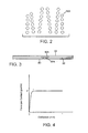
- FIG. 2 depicts an exemplary layout of a set of flat contacts mounted on the print cartridge of FIG. 1.
- FIG. 3 is a diagrammatic side view illustration of an exemplary interaction between a flat contact on the print cartridge, a dimple contact on the cartridge stall, and the Z axis conductive elastomer layer.
- FIG. 4 shows an exemplary force versus deflection characteristic, for force exerted on a single contact by the spring of the system of FIG. 1A.
- FIG. 5 is an exemplary embodiment of the elastomer layer of the interconnect system.
- FIG. 6 is a simplified cross-sectional view taken along line 6-6 of FIG. 5.
- FIG. 7 is an exploded isometric view of an exemplary embodiment of a printer carriage employing an interconnect system in accordance with the invention.
- FIGS. 1A-1B illustrate in schematic fashion an exemplary embodiment of an interconnect system employing the invention.
- An inkjet print cartridge 60 is mounted in a stall 70 during printing operations.
- the stall can be fixed in position on the printer, or more typically, fabricated on a movable carriage.
- To energize the cartridge printhead (not shown in FIG. 1) an electrical interconnect is made with the cartridge when it is in the mounted position.
- the print cartridge includes a body 62 with a body surface 64 on which a TAB circuit 66 is mounted.
- the circuit 66 includes a planar set of spaced gold or palladium plated flat contacts.
- An exemplary layout of a set of contacts 66A is shown in FIG. 2.
- the contacts 66A have a nominal diameter of 1.4 mm, and have a minimum spacing of 0.20 mm between contacts, but larger or smaller contacts, with different spacings, can be employed as well.
- the interconnect system 50 includes a set of gold plated dimple contacts 82 fabricated on substrate 80. It will be appreciated that the use of cartridge-mounted flat contacts which mate against a corresponding set of dimple contacts on a carriage to establish an electrical interconnect is well known.
- the dimple contacts are nominally 0.8 mm rounded dimples which protrude 0.15 mm from the substrate surface, but larger or smaller contacts can be used, depending on requirements for a particular application.
- the substrate 80 is mounted on a stiff plate 84, which in turn is mounted for movement along a limited range of movement along the Z axis 40.
- the plate 84 is mounted to a sliding bracket comprising walls or posts 86A, 86B, which slide in grooves or holes 88A, 88B formed in housing 88.
- the range of movement in the Z axis is on the order of 1.0 to 1.5 mm, although larger or smaller ranges of movement may be employed, depending on the application requirements.
- the stiff plate on its sliding bracket has a standoff block 93 mounted to its lower surface, and is biased to an extended position by a dome structure 90 which contacts the block 93.
- Dome springs are used for such purposes as biasing push-button switches, for example.
- the dome structure 90 is fabricated to provide a substantially constant bias force against the stiff plate when it is placed under compression.
- the plate 84 and its support thus allow some compliant movement of the substrate 80 in response to insertion forces occurring during mounting of the print cartridge 60.
- the compliant movement is needed to accommodate the tolerances affecting the fit between the various components of the interconnect system and its mounting structures.
- a Z axis conductive elastomer layer 92 is interposed between contacts 66 and 82.
- the layer 92 is simply laid in place without mechanical attachment, although other applications may employ means for holding the layer 92 in place, such as adhesive or mechanical attachment.
- the layer 92 has isolated, conductive elements arranged in alignment with the Z axis, such as thin wires potted in an insulator, which have exposed contacts on the upper and lower surfaces of the layer 90.
- Z-axis conductive elastomer layers are commercially available, e.g., the GB matrix line of conductive elastomers marketed by Shin-Etsu Polymer America, Inc., Newark, CA.
- the thickness of the layer and the pitch spacing of conductors in the layer are determined according to parameters of a given application.
- the layer has a layer thickness of .5 mm, and a conductor pitch of .1 mm.
- FIG. 1A shows the print cartridge 60 partially inserted into the stall 70, but not fully seated, so that the contacts 66A are not brought into contact with the layer 92.
- FIG. 1B shows the cartridge 60 fully seated in the stall 70, with the contacts 66A on circuit 66 seated in compression against layer 92.
- the stall 70 typically has datum contact points (not shown) which interface against corresponding datum surfaces (not shown) on the print cartridge 60, to accurately locate the cartridge 60 in the stall 70, with some type of detent or latch mechanism (not shown) to hold the cartridge 60 in its located position shown in FIG. 1B.
- the compression force against the layer 92 in turn creates a compression force of layer 92 against the dimple contacts 82. This is shown in FIG. 3 for exemplary contacts 66A and 82A.
- the layer 92 has a matrix of electrically conductive filaments 94 which are surrounded by dielectric material such as silicon rubber.
- the filaments provide one-directional (Z-axis only) conductive paths, without cross-conducting in the X or Y axes.
- the filaments extend between the opposed broad surfaces 92A, 92B of the layer 92, so that ends 94A, 94B of the filaments are exposed on the surfaces.
- the filaments are arranged in spaced relation forming a filament matrix, of pitch p.
- the filaments are stiffer than the elastomer material, and so when the elastomer layer is compressed, the ends of the filaments can make contact with surfaces in compression against the surfaces of the layer.
- the distribution of filaments in the layer is uniform.
- the filament distribution can be custom designed to conform to the contact pattern with which the filaments will make contact.
- the dome spring 90 is fabricated to provide a constant force on each contact over its limited range of expected movement.
- FIG. 4 shows an exemplary suitable force versus deflection characteristic, for force exerted on a single contact by the spring.
- Other spring structures could alternatively be used, e.g., a washer spring or an elastomer spring.
- the spring 90 can be omitted, and the elastomer layer 92 provides sufficient resilience and spring pressure to take up any tolerances in the fit between the cartridge and the carriage contacts. In this case, the layer 92 can be made thicker to provide sufficient resilience.
- the elastomer layer 92 serves as a buffer layer between the flat contacts 66A and the dimple contacts 82, preventing direct mechanical contact between the respective sets of contacts, while providing an electrical path between conductive contacts aligned in the Z axis with respect to one another.
- wear on the respective sets of contacts 66A, 82 is significantly reduced, allowing the thickness of the gold or other protective layer to be substantially reduced.
- This provides a cost saving in reduced material cost, and also savings in the manufacturing process.
- a relatively thin layer can be applied by an immersion process, also known as a flash process. For example, a layer on the order of 2 micro-inches to 4 micro-inches can be employed in one application, rather than an electroplated gold layer of 30 micro-inch thickness.
- Another function provided by the layer 92 is a shielding function, wherein the layer 92 shields both sets of electrical contacts from the environment, reducing corrosion.
- the layer 92 shields both sets of electrical contacts from the environment, reducing corrosion.
- stray ink droplets and spray can come into contact with the elements such as the carriage, and the layer 92 which shields both sets of contacts can reduce or eliminate the contact exposure to particles and moisture.
- FIG. 7 is a simplified exploded isometric view of an exemplary carriage structure 150 which is adapted to employ an interconnect system according to the invention.
- This carriage structure comprises a body 152, typically fabricated of an engineering plastic material.
- the body is provided with rod bracket features 154 for mounting the carriage for sliding movement along a carriage slider rod.
- the carriage 150 in this example is adapted with two stalls indicated generally as stalls 156,158 formed in the carriage base 155.
- a print cartridge (not shown in FIG. 7) will be mounted in each stall.
- each stall 156, 158 has defined therein a pocket 160, 162 for receiving a dome spring member.
- the spring member 164 is placed in pocket 160, and a stiff plate 166 is fitted over the spring member.
- a flexible circuit board 168 is fitted over the plates, and carries the dimple electrical contacts.
- the circuit board 168 includes circuit traces which typically connect to a wiring ribbon leading to a printer controller board (not shown), in an exemplary embodiment.
- a Z axis conductive elastomer layer 170 is placed over the dimple contacts, for making contact with the print cartridge electrical contacts when the print cartridge is installed into the carriage.
- Alignment pins (not shown) can be used to align the flexible circuit board and the elastomer layer.
Abstract

Description
- Print cartridges are typically mounted in a stall or chute for positioning in relation to a print zone. The cartridge and the stall are each provided with electrical contacts, so that an electrical interconnect between the cartridge and the stall can be established. In many print cartridges, the cartridge electrical contacts are provided on a THA, a TAB (Tape Automated Bonded) head assembly, flexible circuit which is bonded to the cartridge body. The stall also typically has a flexible circuit board with electrical contacts which are located to make contact with corresponding contacts on the THA circuit on the cartridge. The circuit contacts are typically copper or nickel contacts, which would be subject to corrosion. A gold or other protective metal layer, e.g. palladium, is formed over the copper or nickel contacts, to prevent corrosion. A thick gold layer, e.g. on the order of 30 microinches in thickness, is typically electroplated onto the contacts in order to survive multiple insertions of the cartridge into the stall, since gold wears off with every insertion. This adds to the expense of the print cartridge.
- An interconnect system for a device stall adapted to receive an inkjet device having a first set of electrical contact surfaces on a device surface. A second set of electrical contact surfaces is provided in a device stall. Respective ones of the first set and the second set are in facing alignment when the device is installed in the stall. An elastomeric layer is disposed between and in contact with the first and second sets of electrical contact surfaces, having a plurality of isolated conductive filaments or wires disposed therein between a first layer surface and a second layer surface. Conductor ends are exposed at the first and second layer surfaces, providing isolated electrical continuity between respective ones of the first set and the second set of electrical contact surfaces.
- Features and advantages of the disclosure will readily be appreciated by persons skilled in the art from the following detailed description when read in conjunction with the drawing wherein:
- FIG. 1A is a side view illustrating an exemplary embodiment of an interconnect system using a conductive z-axis elastomer, showing a print cartridge in a stall, just above an engaged position. FIG. 1B is a side view similar to FIG. 1A, but showing the print cartridge in an engaged position with stall electrical contacts.
- FIG. 2 depicts an exemplary layout of a set of flat contacts mounted on the print cartridge of FIG. 1.
- FIG. 3 is a diagrammatic side view illustration of an exemplary interaction between a flat contact on the print cartridge, a dimple contact on the cartridge stall, and the Z axis conductive elastomer layer.
- FIG. 4 shows an exemplary force versus deflection characteristic, for force exerted on a single contact by the spring of the system of FIG. 1A.
- FIG. 5 is an exemplary embodiment of the elastomer layer of the interconnect system.
- FIG. 6 is a simplified cross-sectional view taken along line 6-6 of FIG. 5.
- FIG. 7 is an exploded isometric view of an exemplary embodiment of a printer carriage employing an interconnect system in accordance with the invention.
- In the following detailed description and in the several figures of the drawing, like elements are identified with like reference numerals.
- FIGS. 1A-1B illustrate in schematic fashion an exemplary embodiment of an interconnect system employing the invention. An
inkjet print cartridge 60 is mounted in astall 70 during printing operations. The stall can be fixed in position on the printer, or more typically, fabricated on a movable carriage. To energize the cartridge printhead (not shown in FIG. 1), an electrical interconnect is made with the cartridge when it is in the mounted position. The print cartridge includes abody 62 with abody surface 64 on which aTAB circuit 66 is mounted. Thecircuit 66 includes a planar set of spaced gold or palladium plated flat contacts. An exemplary layout of a set ofcontacts 66A is shown in FIG. 2. In this exemplary embodiment, thecontacts 66A have a nominal diameter of 1.4 mm, and have a minimum spacing of 0.20 mm between contacts, but larger or smaller contacts, with different spacings, can be employed as well. - The
interconnect system 50 includes a set of gold plateddimple contacts 82 fabricated onsubstrate 80. It will be appreciated that the use of cartridge-mounted flat contacts which mate against a corresponding set of dimple contacts on a carriage to establish an electrical interconnect is well known. In the exemplary embodiment, the dimple contacts are nominally 0.8 mm rounded dimples which protrude 0.15 mm from the substrate surface, but larger or smaller contacts can be used, depending on requirements for a particular application. - The
substrate 80 is mounted on astiff plate 84, which in turn is mounted for movement along a limited range of movement along theZ axis 40. In this exemplary embodiment, theplate 84 is mounted to a sliding bracket comprising walls orposts holes housing 88. In one exemplary embodiment, the range of movement in the Z axis is on the order of 1.0 to 1.5 mm, although larger or smaller ranges of movement may be employed, depending on the application requirements. The stiff plate on its sliding bracket has astandoff block 93 mounted to its lower surface, and is biased to an extended position by adome structure 90 which contacts theblock 93. Dome springs are used for such purposes as biasing push-button switches, for example. In contrast to these "snap" switches, however, thedome structure 90 is fabricated to provide a substantially constant bias force against the stiff plate when it is placed under compression. Theplate 84 and its support thus allow some compliant movement of thesubstrate 80 in response to insertion forces occurring during mounting of theprint cartridge 60. The compliant movement is needed to accommodate the tolerances affecting the fit between the various components of the interconnect system and its mounting structures. - Instead of bringing the cartridge
flat contacts 66 into direct contact with thedimple contacts 82, a Z axisconductive elastomer layer 92 is interposed betweencontacts layer 92 is simply laid in place without mechanical attachment, although other applications may employ means for holding thelayer 92 in place, such as adhesive or mechanical attachment. Thelayer 92 has isolated, conductive elements arranged in alignment with the Z axis, such as thin wires potted in an insulator, which have exposed contacts on the upper and lower surfaces of thelayer 90. Z-axis conductive elastomer layers are commercially available, e.g., the GB matrix line of conductive elastomers marketed by Shin-Etsu Polymer America, Inc., Newark, CA. The thickness of the layer and the pitch spacing of conductors in the layer are determined according to parameters of a given application. For one exemplary application, the layer has a layer thickness of .5 mm, and a conductor pitch of .1 mm. - FIG. 1A shows the
print cartridge 60 partially inserted into thestall 70, but not fully seated, so that thecontacts 66A are not brought into contact with thelayer 92. FIG. 1B shows thecartridge 60 fully seated in thestall 70, with thecontacts 66A oncircuit 66 seated in compression againstlayer 92. Thestall 70 typically has datum contact points (not shown) which interface against corresponding datum surfaces (not shown) on theprint cartridge 60, to accurately locate thecartridge 60 in thestall 70, with some type of detent or latch mechanism (not shown) to hold thecartridge 60 in its located position shown in FIG. 1B. The compression force against thelayer 92 in turn creates a compression force oflayer 92 against thedimple contacts 82. This is shown in FIG. 3 forexemplary contacts - An exemplary embodiment of the
elastomer layer 92 is illustrated further in the top view of FIG. 5 and the simplified cross-sectional view of FIG. 6. Thelayer 92 has a matrix of electricallyconductive filaments 94 which are surrounded by dielectric material such as silicon rubber. The filaments provide one-directional (Z-axis only) conductive paths, without cross-conducting in the X or Y axes. The filaments extend between the opposedbroad surfaces layer 92, so that ends 94A, 94B of the filaments are exposed on the surfaces. The filaments are arranged in spaced relation forming a filament matrix, of pitch p. The filaments are stiffer than the elastomer material, and so when the elastomer layer is compressed, the ends of the filaments can make contact with surfaces in compression against the surfaces of the layer. In one exemplary embodiment, the distribution of filaments in the layer is uniform. However, for some applications, the filament distribution can be custom designed to conform to the contact pattern with which the filaments will make contact. - The
dome spring 90 is fabricated to provide a constant force on each contact over its limited range of expected movement. FIG. 4 shows an exemplary suitable force versus deflection characteristic, for force exerted on a single contact by the spring. Other spring structures could alternatively be used, e.g., a washer spring or an elastomer spring. For some applications, thespring 90 can be omitted, and theelastomer layer 92 provides sufficient resilience and spring pressure to take up any tolerances in the fit between the cartridge and the carriage contacts. In this case, thelayer 92 can be made thicker to provide sufficient resilience. - The
elastomer layer 92 serves as a buffer layer between theflat contacts 66A and thedimple contacts 82, preventing direct mechanical contact between the respective sets of contacts, while providing an electrical path between conductive contacts aligned in the Z axis with respect to one another. As a result, wear on the respective sets ofcontacts - Another function provided by the
layer 92 is a shielding function, wherein thelayer 92 shields both sets of electrical contacts from the environment, reducing corrosion. In applications such as inkjet printers, stray ink droplets and spray can come into contact with the elements such as the carriage, and thelayer 92 which shields both sets of contacts can reduce or eliminate the contact exposure to particles and moisture. - An exemplary application for an interconnect system in accordance with the invention is in a swath type printer having a movable carriage mounted on a slider rod. FIG. 7 is a simplified exploded isometric view of an
exemplary carriage structure 150 which is adapted to employ an interconnect system according to the invention. This carriage structure comprises abody 152, typically fabricated of an engineering plastic material. The body is provided with rod bracket features 154 for mounting the carriage for sliding movement along a carriage slider rod. Thecarriage 150 in this example is adapted with two stalls indicated generally as stalls 156,158 formed in thecarriage base 155. A print cartridge (not shown in FIG. 7) will be mounted in each stall. Of course, in other embodiments, the carriage can hold a single cartridge, or more that two cartridges, e.g., four or more. Eachstall pocket stall 156 are shown in FIG. 7. Thespring member 164 is placed inpocket 160, and astiff plate 166 is fitted over the spring member. Aflexible circuit board 168 is fitted over the plates, and carries the dimple electrical contacts. Thecircuit board 168 includes circuit traces which typically connect to a wiring ribbon leading to a printer controller board (not shown), in an exemplary embodiment. A Z axisconductive elastomer layer 170 is placed over the dimple contacts, for making contact with the print cartridge electrical contacts when the print cartridge is installed into the carriage. Alignment pins (not shown) can be used to align the flexible circuit board and the elastomer layer. - Although the foregoing has been a description and illustration of specific embodiments of the invention, various modifications and changes thereto can be made by persons skilled in the art without departing from the scope and spirit of the invention as defined by the following claims. For example, while the interconnect system has been described for use in a print cartridge stall, it can also be used in other applications, such as a stall for an ink supply which has electrical contacts.
Claims (17)
- An interconnect system (50) for a device stall (70) adapted to receive a removable inkjet device (60) having a first set of electrical contact surfaces (66) on a device surface (64), comprising:a second set of electrical contact surfaces (82) in the device stall;respective ones of the first set and the second set in facing alignment when the device is installed in the device stall;an elastomeric layer (92) disposed between and in contact with said first set of electrical contact surfaces and said second set of electrical contact surfaces, when the inkjet device is positioned in the stall, said elastomeric layer having a plurality of aligned conductive filaments or wires (94) disposed therein between a first layer surface and a second layer surface, and having conductor ends (94A, 94B) exposed at the first and second layer surfaces, providing isolated electrical continuity between said respective ones of the first set and the second set of electrical contact surfaces.
- A system according to Claim 1, further comprising:a spring structure (90) providing a bias force against said second set of electrical contact surfaces through a deflection range.
- A system according to Claim 2, wherein the spring structure provides a substantially constant bias force over said deflection range.
- A system according to Claim 2 or Claim 3, wherein the spring structure comprises a dome spring element.
- A system according to Claim 2, wherein said second set of electrical contact surfaces is fabricated on a first surface of a flexible circuit board (80), and said spring structure is disposed to exert said bias force on a second surface of the flexible circuit board.
- A system according to Claim 5, wherein the spring structure comprises:a stiff plate (84) contacting the second surface of the flexible circuit board;a suspension structure (86A, 86B) for suspending the stiff plate relative to a stall base;a spring element (90) disposed between the plate and the stall base.
- A system according to any preceding claim, wherein the device is an inkjet print cartridge.
- A system according to any preceding claim, wherein the stall is formed in a movable carriage (150).
- A system according to any preceding claim, wherein said first set of contact surfaces have a layer of gold or palladium formed therein in a thickness range of 2 micro inches to 4 micro inches.
- A system according to any preceding claim, wherein said second set of contact surfaces have a layer of gold or palladium formed therein in a thickness range of 2 micro inches to 4 micro inches.
- A system according to any preceding claim, wherein said first set of contact surfaces includes flat contact surfaces, and said second set of contact surfaces includes protruding dimple contact surfaces.
- A system according to any preceding claim, wherein the elastomeric layer includes a dielectric elastomer material in which the plurality of conductive filaments or wires are embedded to provide electrical isolation in directions transverse to the filaments or wires.
- A system according to any preceding claim, wherein respective ones or groups of the conductor ends make electrical contact with the first set and the second set of electrical contact surfaces.
- A system according to any preceding claim, wherein the elastomeric layer shields the first set of contacts and the second set of contacts from environmental contamination when the inkjet device is positioned in the stall.
- A system according to any preceding claim, wherein the elastomeric layer has a thickness of about .5 mm.
- A method for electrically connecting an inkjet device (60) in a device stall (70), comprising:inserting the device into the device stall;contacting a first surface of a dielectric elastomer layer (92) with a device set of electrical contact surfaces (66) on a device body (62), said elastomeric layer having a plurality of aligned conductive filaments or wires (94) disposed therein between the first layer surface and a second layer surface, and having conductor ends (94A, 94B) exposed at the first and second layer surfaces;compressing the dielectric elastomer layer between the device set of electrical contact surfaces and a stall set of electrical contacts (82), said stall set of electrical contacts in contact with the second layer surface, providing isolated electrical continuity between said respective ones of the device set of electrical contacts and the stall set of electrical contact surfaces without making direct physical contact between said respective ones of said device and said stall contacts.
- The method of Claim 16, wherein the cartridge set of electrical contact surfaces includes flat contact surfaces, and the stall set of electrical contact surfaces include protruding dimple contact surfaces.
Applications Claiming Priority (2)
| Application Number | Priority Date | Filing Date | Title |
|---|---|---|---|
| US280249 | 2002-10-25 | ||
| US10/280,249 US6776475B2 (en) | 2002-10-25 | 2002-10-25 | Interconnect system and method for inkjet devices using conductive elastomer |
Publications (3)
| Publication Number | Publication Date |
|---|---|
| EP1413436A2 true EP1413436A2 (en) | 2004-04-28 |
| EP1413436A3 EP1413436A3 (en) | 2005-11-16 |
| EP1413436B1 EP1413436B1 (en) | 2007-11-07 |
Family
ID=32069369
Family Applications (1)
| Application Number | Title | Priority Date | Filing Date |
|---|---|---|---|
| EP03010415A Expired - Fee Related EP1413436B1 (en) | 2002-10-25 | 2003-05-08 | Apparatus and method for electrical interconnection for inkjet devices |
Country Status (4)
| Country | Link |
|---|---|
| US (1) | US6776475B2 (en) |
| EP (1) | EP1413436B1 (en) |
| JP (1) | JP2004142464A (en) |
| DE (1) | DE60317286T2 (en) |
Cited By (1)
| Publication number | Priority date | Publication date | Assignee | Title |
|---|---|---|---|---|
| EP1844939A1 (en) * | 2006-04-11 | 2007-10-17 | 3T Supplies AG | Ink cartridge |
Families Citing this family (2)
| Publication number | Priority date | Publication date | Assignee | Title |
|---|---|---|---|---|
| KR100584611B1 (en) * | 2004-11-27 | 2006-06-01 | 삼성전자주식회사 | Inkjet printer |
| US8251494B2 (en) * | 2009-11-30 | 2012-08-28 | Eastman Kodak Company | Bondable printed wiring with improved wear resistance |
Citations (4)
| Publication number | Priority date | Publication date | Assignee | Title |
|---|---|---|---|---|
| US5045249A (en) * | 1986-12-04 | 1991-09-03 | At&T Bell Laboratories | Electrical interconnection by a composite medium |
| US5140405A (en) * | 1990-08-30 | 1992-08-18 | Micron Technology, Inc. | Semiconductor assembly utilizing elastomeric single axis conductive interconnect |
| US5461482A (en) * | 1993-04-30 | 1995-10-24 | Hewlett-Packard Company | Electrical interconnect system for a printer |
| US6003974A (en) * | 1993-04-30 | 1999-12-21 | Hewlett-Packard Company | Unitary interconnect system for an inkjet printer |
Family Cites Families (2)
| Publication number | Priority date | Publication date | Assignee | Title |
|---|---|---|---|---|
| US5598194A (en) | 1993-04-30 | 1997-01-28 | Hewlett-Packard Company | Wiping structure for cleaning electrical contacts for a printer and ink cartridge |
| US6231168B1 (en) | 1999-04-30 | 2001-05-15 | Hewlett-Packard Company | Ink jet print head with flow control manifold shape |
-
2002
- 2002-10-25 US US10/280,249 patent/US6776475B2/en not_active Expired - Fee Related
-
2003
- 2003-05-08 DE DE60317286T patent/DE60317286T2/en not_active Expired - Fee Related
- 2003-05-08 EP EP03010415A patent/EP1413436B1/en not_active Expired - Fee Related
- 2003-10-24 JP JP2003364108A patent/JP2004142464A/en active Pending
Patent Citations (4)
| Publication number | Priority date | Publication date | Assignee | Title |
|---|---|---|---|---|
| US5045249A (en) * | 1986-12-04 | 1991-09-03 | At&T Bell Laboratories | Electrical interconnection by a composite medium |
| US5140405A (en) * | 1990-08-30 | 1992-08-18 | Micron Technology, Inc. | Semiconductor assembly utilizing elastomeric single axis conductive interconnect |
| US5461482A (en) * | 1993-04-30 | 1995-10-24 | Hewlett-Packard Company | Electrical interconnect system for a printer |
| US6003974A (en) * | 1993-04-30 | 1999-12-21 | Hewlett-Packard Company | Unitary interconnect system for an inkjet printer |
Cited By (1)
| Publication number | Priority date | Publication date | Assignee | Title |
|---|---|---|---|---|
| EP1844939A1 (en) * | 2006-04-11 | 2007-10-17 | 3T Supplies AG | Ink cartridge |
Also Published As
| Publication number | Publication date |
|---|---|
| US20040080577A1 (en) | 2004-04-29 |
| DE60317286D1 (en) | 2007-12-20 |
| DE60317286T2 (en) | 2008-08-28 |
| US6776475B2 (en) | 2004-08-17 |
| EP1413436A3 (en) | 2005-11-16 |
| EP1413436B1 (en) | 2007-11-07 |
| JP2004142464A (en) | 2004-05-20 |
Similar Documents
| Publication | Publication Date | Title |
|---|---|---|
| EP0505859B1 (en) | Electronic package for high density applications | |
| EP0286258B1 (en) | Hybrid interconnect lead frame for thermal ink jet printhead and methods of manufacture and connection | |
| US5533904A (en) | Electrical interconnect system for multiple flexible circuits | |
| US5109596A (en) | Adapter arrangement for electrically connecting flat wire carriers | |
| EP1503458B1 (en) | Electric connector | |
| US4998886A (en) | High density stacking connector | |
| US5338208A (en) | High density electronic connector and method of assembly | |
| KR100325575B1 (en) | Electrical contact of devices and conductive interconnect pads for use with the printer | |
| US6572396B1 (en) | Low or zero insertion force connector for printed circuit boards and electrical devices | |
| US4843313A (en) | Integrated circuit package carrier and test device | |
| US20060244111A1 (en) | Electrical connecting member capable of achieving stable connection with a simple structure and connector using the same | |
| JPH04312773A (en) | Electric connector assenbly | |
| JPH05196692A (en) | Connector assembly for testing integrated circuit package | |
| US5228189A (en) | Adapter arrangement for electrically connecting flat wire carriers | |
| CA2167065A1 (en) | Edge-connecting printed circuit board | |
| US5084672A (en) | Multi-point probe assembly for testing electronic device | |
| US6323583B1 (en) | Piezoelectric transducer for incorporation into a module | |
| JPH06163098A (en) | Conductive elastomer interface for pin-grid array | |
| US6776475B2 (en) | Interconnect system and method for inkjet devices using conductive elastomer | |
| JP4746035B2 (en) | Electrical connection device | |
| JPH06260237A (en) | Connector structure | |
| JPH11258295A (en) | Energizing device | |
| CA1256315A (en) | Thermal print head | |
| US5573418A (en) | Press-in connection type structure for electric part | |
| EP0380342A2 (en) | Electrical contact |
Legal Events
| Date | Code | Title | Description |
|---|---|---|---|
| PUAI | Public reference made under article 153(3) epc to a published international application that has entered the european phase |
Free format text: ORIGINAL CODE: 0009012 |
|
| AK | Designated contracting states |
Kind code of ref document: A2 Designated state(s): AT BE BG CH CY CZ DE DK EE ES FI FR GB GR HU IE IT LI LU MC NL PT RO SE SI SK TR |
|
| AX | Request for extension of the european patent |
Extension state: AL LT LV MK |
|
| PUAL | Search report despatched |
Free format text: ORIGINAL CODE: 0009013 |
|
| AK | Designated contracting states |
Kind code of ref document: A3 Designated state(s): AT BE BG CH CY CZ DE DK EE ES FI FR GB GR HU IE IT LI LU MC NL PT RO SE SI SK TR |
|
| AX | Request for extension of the european patent |
Extension state: AL LT LV MK |
|
| 17P | Request for examination filed |
Effective date: 20051121 |
|
| AKX | Designation fees paid |
Designated state(s): DE FR GB |
|
| GRAP | Despatch of communication of intention to grant a patent |
Free format text: ORIGINAL CODE: EPIDOSNIGR1 |
|
| GRAS | Grant fee paid |
Free format text: ORIGINAL CODE: EPIDOSNIGR3 |
|
| GRAA | (expected) grant |
Free format text: ORIGINAL CODE: 0009210 |
|
| AK | Designated contracting states |
Kind code of ref document: B1 Designated state(s): DE FR GB |
|
| REG | Reference to a national code |
Ref country code: GB Ref legal event code: FG4D |
|
| REF | Corresponds to: |
Ref document number: 60317286 Country of ref document: DE Date of ref document: 20071220 Kind code of ref document: P |
|
| ET | Fr: translation filed | ||
| PLBE | No opposition filed within time limit |
Free format text: ORIGINAL CODE: 0009261 |
|
| STAA | Information on the status of an ep patent application or granted ep patent |
Free format text: STATUS: NO OPPOSITION FILED WITHIN TIME LIMIT |
|
| 26N | No opposition filed |
Effective date: 20080808 |
|
| PGFP | Annual fee paid to national office [announced via postgrant information from national office to epo] |
Ref country code: DE Payment date: 20080630 Year of fee payment: 6 |
|
| PGFP | Annual fee paid to national office [announced via postgrant information from national office to epo] |
Ref country code: GB Payment date: 20080529 Year of fee payment: 6 |
|
| GBPC | Gb: european patent ceased through non-payment of renewal fee |
Effective date: 20090508 |
|
| PG25 | Lapsed in a contracting state [announced via postgrant information from national office to epo] |
Ref country code: GB Free format text: LAPSE BECAUSE OF NON-PAYMENT OF DUE FEES Effective date: 20090508 |
|
| PG25 | Lapsed in a contracting state [announced via postgrant information from national office to epo] |
Ref country code: DE Free format text: LAPSE BECAUSE OF NON-PAYMENT OF DUE FEES Effective date: 20091201 |
|
| REG | Reference to a national code |
Ref country code: FR Ref legal event code: PLFP Year of fee payment: 13 |
|
| PGFP | Annual fee paid to national office [announced via postgrant information from national office to epo] |
Ref country code: FR Payment date: 20150422 Year of fee payment: 13 |
|
| REG | Reference to a national code |
Ref country code: FR Ref legal event code: ST Effective date: 20170131 |
|
| PG25 | Lapsed in a contracting state [announced via postgrant information from national office to epo] |
Ref country code: FR Free format text: LAPSE BECAUSE OF NON-PAYMENT OF DUE FEES Effective date: 20160531 |