EP1415621A2 - Shoulder prosthesis - Google Patents
Shoulder prosthesis Download PDFInfo
- Publication number
- EP1415621A2 EP1415621A2 EP03010285A EP03010285A EP1415621A2 EP 1415621 A2 EP1415621 A2 EP 1415621A2 EP 03010285 A EP03010285 A EP 03010285A EP 03010285 A EP03010285 A EP 03010285A EP 1415621 A2 EP1415621 A2 EP 1415621A2
- Authority
- EP
- European Patent Office
- Prior art keywords
- shaft
- shoulder joint
- joint prosthesis
- prosthesis according
- support
- Prior art date
- Legal status (The legal status is an assumption and is not a legal conclusion. Google has not performed a legal analysis and makes no representation as to the accuracy of the status listed.)
- Granted
Links
Images


Classifications
-
- A—HUMAN NECESSITIES
- A61—MEDICAL OR VETERINARY SCIENCE; HYGIENE
- A61F—FILTERS IMPLANTABLE INTO BLOOD VESSELS; PROSTHESES; DEVICES PROVIDING PATENCY TO, OR PREVENTING COLLAPSING OF, TUBULAR STRUCTURES OF THE BODY, e.g. STENTS; ORTHOPAEDIC, NURSING OR CONTRACEPTIVE DEVICES; FOMENTATION; TREATMENT OR PROTECTION OF EYES OR EARS; BANDAGES, DRESSINGS OR ABSORBENT PADS; FIRST-AID KITS
- A61F2/00—Filters implantable into blood vessels; Prostheses, i.e. artificial substitutes or replacements for parts of the body; Appliances for connecting them with the body; Devices providing patency to, or preventing collapsing of, tubular structures of the body, e.g. stents
- A61F2/02—Prostheses implantable into the body
- A61F2/30—Joints
- A61F2/40—Joints for shoulders
- A61F2/4014—Humeral heads or necks; Connections of endoprosthetic heads or necks to endoprosthetic humeral shafts
-
- A—HUMAN NECESSITIES
- A61—MEDICAL OR VETERINARY SCIENCE; HYGIENE
- A61F—FILTERS IMPLANTABLE INTO BLOOD VESSELS; PROSTHESES; DEVICES PROVIDING PATENCY TO, OR PREVENTING COLLAPSING OF, TUBULAR STRUCTURES OF THE BODY, e.g. STENTS; ORTHOPAEDIC, NURSING OR CONTRACEPTIVE DEVICES; FOMENTATION; TREATMENT OR PROTECTION OF EYES OR EARS; BANDAGES, DRESSINGS OR ABSORBENT PADS; FIRST-AID KITS
- A61F2/00—Filters implantable into blood vessels; Prostheses, i.e. artificial substitutes or replacements for parts of the body; Appliances for connecting them with the body; Devices providing patency to, or preventing collapsing of, tubular structures of the body, e.g. stents
- A61F2/02—Prostheses implantable into the body
- A61F2/30—Joints
- A61F2002/30001—Additional features of subject-matter classified in A61F2/28, A61F2/30 and subgroups thereof
- A61F2002/30316—The prosthesis having different structural features at different locations within the same prosthesis; Connections between prosthetic parts; Special structural features of bone or joint prostheses not otherwise provided for
- A61F2002/30329—Connections or couplings between prosthetic parts, e.g. between modular parts; Connecting elements
- A61F2002/30331—Connections or couplings between prosthetic parts, e.g. between modular parts; Connecting elements made by longitudinally pushing a protrusion into a complementarily-shaped recess, e.g. held by friction fit
- A61F2002/30332—Conically- or frustoconically-shaped protrusion and recess
-
- A—HUMAN NECESSITIES
- A61—MEDICAL OR VETERINARY SCIENCE; HYGIENE
- A61F—FILTERS IMPLANTABLE INTO BLOOD VESSELS; PROSTHESES; DEVICES PROVIDING PATENCY TO, OR PREVENTING COLLAPSING OF, TUBULAR STRUCTURES OF THE BODY, e.g. STENTS; ORTHOPAEDIC, NURSING OR CONTRACEPTIVE DEVICES; FOMENTATION; TREATMENT OR PROTECTION OF EYES OR EARS; BANDAGES, DRESSINGS OR ABSORBENT PADS; FIRST-AID KITS
- A61F2/00—Filters implantable into blood vessels; Prostheses, i.e. artificial substitutes or replacements for parts of the body; Appliances for connecting them with the body; Devices providing patency to, or preventing collapsing of, tubular structures of the body, e.g. stents
- A61F2/02—Prostheses implantable into the body
- A61F2/30—Joints
- A61F2/40—Joints for shoulders
- A61F2/4014—Humeral heads or necks; Connections of endoprosthetic heads or necks to endoprosthetic humeral shafts
- A61F2002/4037—Connections of heads to necks
-
- A—HUMAN NECESSITIES
- A61—MEDICAL OR VETERINARY SCIENCE; HYGIENE
- A61F—FILTERS IMPLANTABLE INTO BLOOD VESSELS; PROSTHESES; DEVICES PROVIDING PATENCY TO, OR PREVENTING COLLAPSING OF, TUBULAR STRUCTURES OF THE BODY, e.g. STENTS; ORTHOPAEDIC, NURSING OR CONTRACEPTIVE DEVICES; FOMENTATION; TREATMENT OR PROTECTION OF EYES OR EARS; BANDAGES, DRESSINGS OR ABSORBENT PADS; FIRST-AID KITS
- A61F2/00—Filters implantable into blood vessels; Prostheses, i.e. artificial substitutes or replacements for parts of the body; Appliances for connecting them with the body; Devices providing patency to, or preventing collapsing of, tubular structures of the body, e.g. stents
- A61F2/02—Prostheses implantable into the body
- A61F2/30—Joints
- A61F2/40—Joints for shoulders
- A61F2/4059—Humeral shafts
- A61F2002/4062—Proximal or metaphyseal parts of shafts
- A61F2002/4066—Proximal or metaphyseal parts of shafts for replacement or reinforcement of the greater tubercle
-
- A—HUMAN NECESSITIES
- A61—MEDICAL OR VETERINARY SCIENCE; HYGIENE
- A61F—FILTERS IMPLANTABLE INTO BLOOD VESSELS; PROSTHESES; DEVICES PROVIDING PATENCY TO, OR PREVENTING COLLAPSING OF, TUBULAR STRUCTURES OF THE BODY, e.g. STENTS; ORTHOPAEDIC, NURSING OR CONTRACEPTIVE DEVICES; FOMENTATION; TREATMENT OR PROTECTION OF EYES OR EARS; BANDAGES, DRESSINGS OR ABSORBENT PADS; FIRST-AID KITS
- A61F2220/00—Fixations or connections for prostheses classified in groups A61F2/00 - A61F2/26 or A61F2/82 or A61F9/00 or A61F11/00 or subgroups thereof
- A61F2220/0025—Connections or couplings between prosthetic parts, e.g. between modular parts; Connecting elements
- A61F2220/0033—Connections or couplings between prosthetic parts, e.g. between modular parts; Connecting elements made by longitudinally pushing a protrusion into a complementary-shaped recess, e.g. held by friction fit
Definitions
- the invention relates to a shoulder joint prosthesis with two cooperating Bearing bodies, a shaft and a coupling for connection of the shank with one of the bearing bodies.
- Such a prosthesis is for example from the European patent applications EP 01 811 120.3 and EP 02 018 730.8.
- the object of the invention is, in a shoulder joint prosthesis of the above mentioned type while maintaining flexibility and without interference the connection between the bearing body and shaft for optimal Results also in fractures with a variety of small bone fragments to care.
- the support body by the support body, the gap between bridged the shaft and the bearing body, thereby advantageously a substructure is created, at which bone fragments can support, which favors their growing together.
- the invention is basically independent of whether it is in the Bearing body is about a bearing head or a bearing shell.
- the support surface of the support body executed at least partially convex.
- the lateral surface of the shaft and the Support surface of the support body together at least substantially closed, adjoining the bottom of the bearing body Form surface.
- the support surface of the support body may be at least approximately tangential connect to the lateral surface of the shaft.
- the growth of bone material is further favored when According to one embodiment of the invention, the support surface of the support body is structured.
- the support surface of the support body is in particular without interruption educated.
- the supporting body can be exchangeably connected to the bearing body.
- a modular design can be realized in an advantageous manner, wherein a plurality of bearing bodies having a plurality of Protective bodies can be combined to one for each application optimally fitting configuration.
- the shaft may be provided with a support member which laterally the shaft is seated and in the region of the transition from the shaft into the Support body with its outside in the support surface of the support body forms transitional surface of the shaft.
- the support element can in particular basket or dish-like design.
- the support element can be firmly connected to the shaft, for example welded, be.
- the support member in one piece with be formed the shaft.
- the support element with Breakthroughs be provided.
- the proportion of interruptions due to breakthroughs Sections of the outer surface of the support element in the range of 35% to 45%.
- the ratio X / Y of maximum Outer diameter of the support element in the sagittal X and maximum outer diameter of the support element in the transverse direction Y is in the range of 0.85 to 0.95.
- the coupling can be used for connection to the shaft a clamping section include, by introducing, in particular wrapping, in a Coupling of the shaft a solid, in particular detachable Clamping seat of the coupling in the shaft can be produced.
- the clamping section is cone-like tapered and in a correspondingly shaped, as a coupling receptacle serving counter-form of the shaft can be introduced.
- the clamping section in the with Shaft-connected state a rotationally fixed to a longitudinal axis and formed by its conicity wedged form closure with the counter-form. This allows a self-locking seat of the clamping section in the Gegenform be realized.
- the clamping portion may have a different cross-section from a circular shape exhibit.
- the cross section of the clamping portion elliptical.
- the elliptical cross section of the clamping portion and the counter-shape of the shaft is aligned in its plane is that the big axis of the ellipse in a projection against laterally appears as a vertical.
- the shaft in the plane of the elliptical Cross-section the outline of a provided with rounded corners Rectangles whose long sides parallel to the major axis of Ellipse run.
- Figs. 1 to 8 show a shoulder joint prosthesis according to the prior Technique, whose characteristics, however, with one exception, to the following is also the subject of the shoulder joint prosthesis according to the invention are or can be.
- the exception mentioned is that the Bearing body 101, 112 according to the prior art no support body as explained below in connection with FIGS. 9 to 14 becomes.
- FIGs. 1 and 2 show a first embodiment of a known Shoulder joint prosthesis.
- a shaft 105 is in a humerus 103rd implanted, with the shaft 105 directly in a prepared bone bed is anchored.
- the shaft 105 may be just as well a shaft anchored to bone cement in humerus 103 105 act.
- a bore 116 provided in a counter-mold 115 for a conical Body 107 ends.
- the actual joint will be replaced by one with the conical body 107 rigidly connected bearing head 101 and a bearing shell 102 formed, which in turn with a shoulder bone 104th anchored platform 106 is rigidly connected.
- To anchor the platform 106 are parallel to each other Pin 114 attached to the platform 106, for example, with bone cement or by press fit in prepared holes of the shoulder bone 104 are anchored.
- the conical body 107 here forms a clamping section serving Coupling for connecting the in the example of Figs. 1 and 2 as a bearing head 101 trained bearing body with the shaft 105, the purpose for this serving as a coupling receiving counter-mold 115 for the clamping cone 107.
- the conical body 107 - and corresponding to the counter-mold 115 - have in each case a cross section 110 with a circumference 108, which according to FIG. 3 is elliptical.
- Fig. 4 the desired ratios in an approximately elliptical Cross section shown. They are due to slight shape deviations between the conical body 107 and the counter-mold 115 four contact points P provided that at intense pressure to contact surfaces expand.
- a radial distance 139 of a contact point P is selected such that a normal force N in a contact point P with its line of action in a relatively large distance 136 past the longitudinal axis 109 to Shares of a torque M as changes in normal forces transferred to.
- FIG. 6 Another possibility for a modification of the conical body 107 is shown in Fig. 6.
- To maximize bending moments in the longitudinal axis To be able to transfer 109 finds the tension in two cross sections instead, which are separated by a minimum distance 137. This means that the cone 107 in the middle area an interruption 138 of this minimum distance 137 has.
- the shaft 105 implanted in the humerus 103 has a bore 116 and a counter-mold 115 for a conical body 107th Mistake.
- the conical body is for receiving the spherical shell 112 widened, which in turn encloses a ball head 111 partially.
- the ball head 111 is by a snap or screw connection (not shown) mounted on a platform 106, which via pins 114 in Shoulder bone 104 is anchored.
- the anchoring of the platform 106 may as well have bone screws and protruding ribs in the Shoulder bone 104 done.
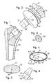
- FIG. 9 to 11 show a part of a shoulder joint prosthesis according to the invention, in a trained as a bearing head bearing body 11 with a shaft 13 is connected.
- the bearing body 11 without shaft 13 shows Fig. 12.
- the bearing body 11 is a cone with elliptical Cross-section formed clamping portion 15 connected in a correspondingly shaped counter-shape of the shaft 13 is einschlagbar to to produce a solid, releasable clamping seat of the cone 15 in the shaft 13.
- the orientation of the bearing body 11 relative to the cone 15 can during the operation according to the respective circumstances within certain limits are chosen arbitrarily.
- This coupling section is also formed such that the bearing body 11 in a during the operation selected relative position with respect to the cone 15 fixed can be.
- the bearing body 11 is provided with a support body 21.
- the support body 21 may be formed integrally with the bearing body 11 or as a separate, connectable to the bearing body 11 component be provided.
- the connection between the support body 21 and the Bearing body 11 may be designed so tight that bearing body 11 and Support body 21 form a solid, rigid configuration.
- the support body 21 adjustable on the bearing body 11 attach to a suitable for the particular application Configuration to be able to adjust.
- the support body 21 comprises a bowl-like portion 21b and a collar-like portion 21a, whose height - i. whose extension perpendicular to the bottom of the 19th of the bearing body 11 - in the of the collar-like portion 21 a away decreasing direction decreases.
- the support body 21 serves to the gap, which in with the Shank 13 connected bearing body 11 between the bottom 19 of the Lagergropers 11 and the shaft 13 is present, close and with to provide on its outside a support surface 23, at which bone fragments can support them, causing their growing together is favored.
- the support surface 23 closes of the support body 21 to the lateral surface of the shaft 13, which here in the Range of the transition from the shaft 13 into the support body 21 of a laterally seated on the shaft 13, basket-like support member 27 is formed will be discussed in more detail below.
- support body 21 according to the invention can in principle also without a provided on the shaft 13 support basket 27 are used.
- FIG. 11 is connected to the shaft 13 at Bearing body 11 between the support basket 27 of the shaft 13 and the shell-like portion 21 b of the support body 21 has a recess 31 present, to which for releasing the bearing body 11 of the shaft 13 a Tool can be set.
- the support body 21 here comprises only a cup-shaped Section whose outside forms the support surface 23.
- One additional collar-shaped section is not provided in this example, but also in shoulder joint prostheses with a ball cup trained bearing body 11 of the support body 21 is basically an additional Support section e.g. could have in collar shape. apart this also applies to this embodiment in conjunction with The above explained figures accordingly.
- Fig. 15 shows the basket or quiver-shaped shown in Figs. 9-11 and 13 Support member 27 in a view from above along the shaft axis 143 (see eg Fig. 9 and 13), d. H. the shaft axis 143 is perpendicular to the drawing plane in FIG. 15.
- the maximum outer diameter in the sagittal X and the maximum outer diameter in the transverse direction Y is such chosen for all intended within an implant set Sizes of the support member 27, the ratio X / Y in the range of 0.85 to 0.95 is.
- the openings 29 are designed and positioned in such a way that along a circumferential line 141 of the support member 27, the implanted in the State is in a plane which is perpendicular to the shaft axis 143 and in the proximal direction at a distance of 8 mm from the point of intersection 145 between the shaft axis 143 and the head or shell axis 147 runs, the proportion of interrupted due to the openings 29 Sections of the outer surface of the support member 27 in the range of 35% to 45%.
Abstract
Description
Die Erfindung betrifft eine Schultergelenkprothese mit zwei zusammenwirkenden Lagerkörpern, einem Schaft und einer Kupplung zum Verbindung des Schaftes mit einem der Lagerkörper.The invention relates to a shoulder joint prosthesis with two cooperating Bearing bodies, a shaft and a coupling for connection of the shank with one of the bearing bodies.
Eine derartige Prothese ist beispielsweise aus den europäischen Patentanmeldungen EP 01 811 120.3 und EP 02 018 730.8 bekannt.Such a prosthesis is for example from the European patent applications EP 01 811 120.3 and EP 02 018 730.8.
Bei einem derartigen flexiblen System ist der in den Oberarm einzusetzende Schaft nicht fest mit dem Lagerkörper verbunden, sondern es können für den jeweiligen Fall passende, aus einem Baukastensystem auswählbare Lagerkörper über die Kupplung mit dem Schaft verbunden werden, wobei es außerdem möglich ist, unterschiedliche Stellungen des Lagerkörpers relativ zum Schaft zu realisieren. Diese Flexibilität erfordert es, den Schaft derart auszubilden, dass im Bereich des Übergangs zwischen Schaft und Lagerkörper ausreichend Platz vorhanden ist, um verschiedene Lagerkörper anzubringen bzw. verschiedene Relativstellungen der Lagerkörper zu ermöglichen. Bei Frakturen mit einer Vielzahl von kleinen Knochenfragmenten kann es zu Problemen beim Zusammenwachsen der einzelnen Trümmerstücke kommen.In such a flexible system that is to be used in the upper arm Shank not firmly connected to the bearing body, but it can suitable for the respective case, selectable from a modular system Bearing body are connected via the coupling with the shaft, it also being possible to have different positions of the bearing body to realize relative to the shaft. This flexibility requires that Shank form such that in the transition area between Shaft and bearing body sufficient space is available to different To install bearing body or different relative positions of the bearing body to enable. For fractures with a variety of small bone fragments It can lead to problems when growing together Debris comes.
Aufgabe der Erfindung ist es, bei einer Schultergelenkprothese der eingangs genannten Art unter Beibehaltung der Flexibilität und ohne Beeinträchtigung der Verbindung zwischen Lagerkörper und Schaft für optimale Ergebnisse auch bei Frakturen mit einer Vielzahl von kleinen Knochenfragmenten zu sorgen. The object of the invention is, in a shoulder joint prosthesis of the above mentioned type while maintaining flexibility and without interference the connection between the bearing body and shaft for optimal Results also in fractures with a variety of small bone fragments to care.
Die Lösung dieser Aufgabe erfolgt durch die Merkmale des Anspruchs 1 und insbesondere dadurch, dass sich an die Unterseite des mit dem Schaft verbindbaren Lagerkörpers ein Stützkörper anschließt, der im mit dem Schaft verbundenen Zustand mit einer äußeren Stützfläche eine zwischen dem Lagerkörper und dem Schaft vorhandene Lücke zumindest teilweise derart ausfüllt, dass das Zusammenwachsen von Knochenfragmenten begünstigt wird.The solution of this object is achieved by the features of claim 1 and in particular by the fact that to the bottom of the with Shank connectable bearing body connects a support body, which in with the shaft connected state with an outer support surface between the bearing body and the shaft existing gap at least partially filled in such a way that the merging of bone fragments is favored.
Erfindungsgemäß wird durch den Stützkörper der Zwischenraum zwischen dem Schaft und dem Lagerkörper überbrückt, wodurch in vorteilhafterweise ein Unterbau geschaffen wird, an welchem sich Knochenfragmente abstützen können, was deren Zusammenwachsen begünstigt.According to the invention by the support body, the gap between bridged the shaft and the bearing body, thereby advantageously a substructure is created, at which bone fragments can support, which favors their growing together.
Die Erfindung ist grundsätzlich unabhängig davon, ob es sich bei dem Lagerkörper um einen Lagerkopf oder um eine Lagerschale handelt.The invention is basically independent of whether it is in the Bearing body is about a bearing head or a bearing shell.
In einer Weiterbildung der Erfindung ist die Stützfläche des Stützkörpers zumindest bereichsweise konvex ausgeführt.In a development of the invention, the support surface of the support body executed at least partially convex.
Ferner kann vorgesehen sein, dass die Mantelfläche des Schaftes und die Stützfläche des Stützkörpers zusammen eine zumindest im Wesentlichen geschlossene, sich an die Unterseite des Lagerkörpers anschließende Fläche bilden.Furthermore, it can be provided that the lateral surface of the shaft and the Support surface of the support body together at least substantially closed, adjoining the bottom of the bearing body Form surface.
Die Stützfläche des Stützkörpers kann zumindest näherungsweise tangential an die Mantelfläche des Schaftes anschließen.The support surface of the support body may be at least approximately tangential connect to the lateral surface of the shaft.
Das Heranwachsen von Knochenmaterial wird weiter begünstigt, wenn gemäß einer Ausführungsform der Erfindung die Stützfläche des Stützkörpers strukturiert ist. The growth of bone material is further favored when According to one embodiment of the invention, the support surface of the support body is structured.
Die Stützfläche des Stützkörpers ist insbesondere durchbrechungsfrei ausgebildet.The support surface of the support body is in particular without interruption educated.
Der Stützköper kann auswechselbar mit dem Lagerkörper verbunden sein. Hierdurch kann in vorteilhafter Weise eine Modulbauweise realisiert werden, bei der eine Mehrzahl von Lagerkörpern mit einer Mehrzahl von Schutzkörpern kombiniert werden kann, um eine für den jeweiligen Anwendungsfall optimal passende Konfiguration zu bilden.The supporting body can be exchangeably connected to the bearing body. As a result, a modular design can be realized in an advantageous manner, wherein a plurality of bearing bodies having a plurality of Protective bodies can be combined to one for each application optimally fitting configuration.
Des Weiteren kann erfindungsgemäß vorgesehen sein, dass bei mit dem Schaft verbundenem Lagerköper zwischen dem Schaft und dem Stützkörper wenigstens eine Aussparung vorhanden ist, an die ein Werkzeug zum Lösen des Lagerkörpers vom Schaft ansetzbar ist.Furthermore, it can be provided according to the invention that when with the Shank associated bearing body between the shaft and the support body at least one recess is present, to which a tool for Loosening of the bearing body from the shaft can be attached.
Der Schaft kann mit einem Stützelement versehen sein, das seitlich auf dem Schaft aufsitzt und im Bereich des Übergangs vom Schaft in den Stützkörper mit seiner Außenseite die in die Stützfläche des Stützköpers übergehende Mantelfläche des Schaftes bildet. Das Stützelement kann insbesondere korb- oder schalenartig ausgebildet sein.The shaft may be provided with a support member which laterally the shaft is seated and in the region of the transition from the shaft into the Support body with its outside in the support surface of the support body forms transitional surface of the shaft. The support element can in particular basket or dish-like design.
Ferner kann das Stützelement fest mit dem Schaft verbunden, beispielsweise verschweißt, sein. Alternativ kann das Stützelement einteilig mit dem Schaft ausgebildet sein.Furthermore, the support element can be firmly connected to the shaft, for example welded, be. Alternatively, the support member in one piece with be formed the shaft.
In einer weiteren Ausgestaltung der Erfindung kann das Stützelement mit Durchbrüchen versehen sein.In a further embodiment of the invention, the support element with Breakthroughs be provided.
Ferner kann vorgesehen sein, dass entlang einer Umfangslinie des Stützelementes, die im implantierten Zustand in einer senkrecht zur Schaftachse und in proximaler Richtung in einem Abstand von 8 mm von dem Schnittpunkt zwischen der Schaftachse und der Kopf- bzw. Schalenachse verlaufenden Ebene liegt, der Anteil der aufgrund der Durchbrüche unterbrochenen Abschnitte der Außenfläche des Stützelementes im Bereich von 35 % bis 45 % liegt.Furthermore, it can be provided that along a circumferential line of the support element, in the implanted state in a direction perpendicular to the shaft axis and in the proximal direction at a distance of 8 mm from the Intersection between the shaft axis and the head or shell axis level, the proportion of interruptions due to breakthroughs Sections of the outer surface of the support element in the range of 35% to 45%.
Des Weiteren kann vorgesehen sein, dass bezogen auf die Orientierung des Stützelementes im implantierten Zustand mit senkrecht zur Transversalebene verlaufender Schaftachse das Verhältnis X/Y aus maximalem Außendurchmesser des Stützelementes in sagittaler Richtung X und maximalem Außendurchmesser des Stützelementes in transversaler Richtung Y im Bereich von 0,85 bis 0,95 liegt.Furthermore, it can be provided that based on the orientation of the support element in the implanted state with perpendicular to the transverse plane extending shaft axis the ratio X / Y of maximum Outer diameter of the support element in the sagittal X and maximum outer diameter of the support element in the transverse direction Y is in the range of 0.85 to 0.95.
Die Kupplung kann zur Verbindung mit dem Schaft einen Spannabschnitt umfassen, mit dem durch Einbringen, insbesondere Einschlagen, in eine Kupplungsaufnahme des Schaftes ein fester, insbesondere wieder lösbarer Spannsitz der Kupplung im Schaft herstellbar ist.The coupling can be used for connection to the shaft a clamping section include, by introducing, in particular wrapping, in a Coupling of the shaft a solid, in particular detachable Clamping seat of the coupling in the shaft can be produced.
Dabei kann vorgesehen sein, dass der Spannabschnitt sich konusartig verjüngt und in eine entsprechend geformte, als Kupplungsaufnahme dienende Gegenform des Schaftes einbringbar ist.It can be provided that the clamping section is cone-like tapered and in a correspondingly shaped, as a coupling receptacle serving counter-form of the shaft can be introduced.
Des Weiteren kann vorgesehen sein, dass der Spannabschnitt im mit dem Schaft verbundenen Zustand einen zu einer Längsachse drehfesten und durch seine Konizität verkeilten Formschluss mit der Gegenform bildet. Hierdurch kann ein selbsthemmender Sitz des Spannabschnitts in der Gegenform realisiert werden. Furthermore, it can be provided that the clamping section in the with Shaft-connected state a rotationally fixed to a longitudinal axis and formed by its conicity wedged form closure with the counter-form. This allows a self-locking seat of the clamping section in the Gegenform be realized.
Der Spannabschnitt kann einen von einer Kreisform abweichenden Querschnitt aufweisen. Vorzugsweise ist der Querschnitt des Spannabschnitts elliptisch.The clamping portion may have a different cross-section from a circular shape exhibit. Preferably, the cross section of the clamping portion elliptical.
Dabei kann vorgesehen sein, dass der elliptische Querschnitt des Spannabschnitts und der Gegenform des Schaftes derart in seiner Ebene ausgerichtet ist, dass die große Achse der Ellipse in einer Projektion gegen lateral als Senkrechte erscheint.It can be provided that the elliptical cross section of the clamping portion and the counter-shape of the shaft is aligned in its plane is that the big axis of the ellipse in a projection against laterally appears as a vertical.
Es hat sich gezeigt, dass hierdurch eine optimale Ausnutzung des Materials und ein Maximum an Festigkeit für die Klemmverbindung zwischen dem Spannabschnitt und der Gegenform erreicht werden kann.It has been shown that this ensures optimum utilization of the material and maximum strength for the clamping connection between the clamping section and the counter-mold can be achieved.
Ferner kann vorgesehen sein, dass der Schaft in der Ebene des elliptischen Querschnitts den Umriss eines mit abgerundeten Ecken versehenen Rechtecks aufweist, dessen langen Seiten parallel zu der großen Achse der Ellipse verlaufen.Furthermore, it can be provided that the shaft in the plane of the elliptical Cross-section the outline of a provided with rounded corners Rectangles whose long sides parallel to the major axis of Ellipse run.
Weitere Ausführungsformen der Erfindung sind in den Unteransprüchen, der Beschreibung sowie der Zeichnung angegeben.Further embodiments of the invention are defined in the subclaims, the description and the drawing.
Die Erfindung wird im Folgenden beispielhaft unter Bezugnahme auf die Zeichnung beschrieben. Es zeigen:
- Fig. 1
- schematisch einen in einem Oberarmknochen implantierten Schaft einer Schultergelenkprothese nach dem Stand der Technik,
- Fig. 2
- schematisch ein künstliches Schultergelenk mit einem als Lagerkopf ausgebildeten Lagerkörper nach dem Stand der Technik, der einen zu dem Schaft von Fig. 1 passenden konischen Körper aufweist,
- Fig. 3
- schematisch einen Querschnitt durch einen konischen Köper gemäß Fig. 2 mit einem elliptisch verlaufenden Umfang,
- Fig. 4
- schematisch einen Schnitt gemäß Fig. 3, an dem eine drehfeste Verkeilung zwischen konischem Körper und Gegenform dargestellt ist,
- Fig. 5
- schematisch einen Schnitt durch einen konischen Körper mit einem ursprünglichen Rechteckquerschnitt nach dem Stand der Technik, an dem nachträglich konische, im Schnitt elliptische Teilflächen passend zu einer Gegenform gemäß Fig. 4 hergestellt wurden,
- Fig. 6
- schematisch einen konischen Körper nach dem Stand der Technik, bei dem im mittleren Bereich der konischen Fläche eine Unterbrechung eingearbeitet ist,
- Fig. 7
- schematisch einen in einem Oberarmknochen implantierten Schaft nach dem Stand der Technik mit einer Gegenform für einen konischen Körper,
- Fig. 8
- schematisch einen zum Schaft von Fig. 7 passenden konischen Körper, der mit einem als Kugelschale ausgebildeten Lagerkörper ein künstliches Schultergelenk zu einem Kugelkopf nach dem Stand der Technik bildet, der über eine Plattform am Schulterknochen befestigt ist,
- Fig. 9
- einen Teil einer erfindungsgemäßen Schultergelenkprothese mit einem als Lagerkopf ausgebildeten Lagerkörper im mit einem Schaft verbundenen Zustand,
- Fig. 10
- eine andere Ansicht der erfindungsgemäßen Schultergelenkprothese von Fig. 9,
- Fig. 11
- eine weitere Ansicht der erfindungsgemäßen Schultergelenkprothese von Fig. 9,
- Fig. 12
- den mit einem Stützkörper und einem Spannkonus versehenen Lagerkörper der erfindungsgemäßen Schultergelenkprothese von Fig. 9,
- Fig. 13
- einen Teil einer anderen Ausführungsform einer erfindungsgemäßen Schultergelenkprothese mit einem als Lagerschale ausgebildeten Lagerkörper,
- Fig. 14
- den mit einem Stützkörper und einem Spannkonus versehenen Lagerkörper der erfindungsgemäßen Schultergelenkprothese von Fig. 13,
- Fig. 15
- eine Ansicht von oben eines Stützelementes einer Schultergelenkprothese gemäß einer Ausführungsform der Erfindung zur Erläuterung eines Außendurchmesserverhältnisses, und
- Fig. 16a und 16 b
- verschiedene Ansichten des Stützelementes von Fig. 15.
- Fig. 1
- 2 schematically shows a shaft of a shoulder joint prosthesis according to the prior art implanted in a humerus bone, FIG.
- Fig. 2
- 1 schematically shows an artificial shoulder joint with a bearing body designed as a bearing head according to the prior art, which has a conical body matching the shaft of FIG. 1, FIG.
- Fig. 3
- 2 schematically shows a cross section through a conical body according to FIG. 2 with an elliptical circumference, FIG.
- Fig. 4
- 3 is a schematic cross-sectional view of a non-rotatable wedging between conical body and counter-mold;
- Fig. 5
- 1 schematically shows a section through a conical body with an original rectangular cross section according to the prior art, on which subsequently conical, in section elliptical partial surfaces have been produced matching a countershape according to FIG. 4, FIG.
- Fig. 6
- 1 schematically shows a conical body according to the prior art, in which an interruption is incorporated in the middle region of the conical surface,
- Fig. 7
- FIG. 2 schematically shows a prior art shank implanted in a humerus with a counter-shape for a conical body, FIG.
- Fig. 8
- 7 schematically shows a conical body matching the shaft of FIG. 7, which, with a bearing body formed as a spherical shell, forms an artificial shoulder joint to a ball head according to the prior art, which is fastened to the shoulder bone via a platform.
- Fig. 9
- a part of a shoulder joint prosthesis according to the invention with a bearing body designed as a bearing head in the state connected to a shaft,
- Fig. 10
- another view of the inventive shoulder joint prosthesis of Fig. 9,
- Fig. 11
- another view of the inventive shoulder joint prosthesis of Fig. 9,
- Fig. 12
- the bearing body provided with a support body and a clamping cone of the shoulder joint prosthesis according to the invention of FIG. 9,
- Fig. 13
- a part of another embodiment of a shoulder joint prosthesis according to the invention with a bearing body designed as a bearing shell,
- Fig. 14
- the bearing body provided with a support body and a clamping cone of the shoulder joint prosthesis according to the invention of FIG. 13,
- Fig. 15
- a top view of a support element of a shoulder joint prosthesis according to an embodiment of the invention for explaining an outer diameter ratio, and
- Fig. 16a and 16 b
- different views of the support element of Fig. 15th
Die Fig. 1 bis 8 zeigen eine Schultergelenkprothese nach dem Stand der
Technik, deren Merkmale jedoch mit einer Ausnahme, auf die nachstehend
eingegangen wird, auch Gegenstand der erfindungsgemäßen Schultergelenkprothese
sind oder sein können. Insoweit sind die Fig. 1 bis 8
sowie die dazugehörige Beschreibung als zu der Erfindung gehörend
offenbart anzusehen. Die erwähnte Ausnahme besteht darin, dass die
Lagerkörper 101, 112 nach dem Stand der Technik keinen Stützkörper
aufweisen, wie er nachstehend in Verbindung mit den Fig. 9 bis 14 erläutert
wird.Figs. 1 to 8 show a shoulder joint prosthesis according to the prior
Technique, whose characteristics, however, with one exception, to the following
is also the subject of the shoulder joint prosthesis according to the invention
are or can be. In that regard, Figs. 1 to 8
and the related description as belonging to the invention
to be revealed. The exception mentioned is that the
Die Fig. 1 und 2 zeigen ein erstes Ausführungsbeispiel einer bekannten
Schultergelenkprothese. Ein Schaft 105 ist in einem Oberarmknochen 103
implantiert, wobei der Schaft 105 direkt in einem vorbereiteten Knochenbett
verankert ist. Bei dem Schaft 105 kann es sich aber ebenso gut um
einen mit Knochenzement im Oberarmknochen 103 verankerten Schaft
105 handeln.Figs. 1 and 2 show a first embodiment of a known
Shoulder joint prosthesis. A
In Richtung einer Längsachse 109 für das eigentliche Schultergelenk ist
eine Bohrung 116 vorgesehen, die in einer Gegenform 115 für einen konischen
Körper 107 endet. Das eigentliche Gelenk wird durch einen mit dem
konischen Körper 107 starr verbundenem Lagerkopf 101 und eine Lagerschale
102 gebildet, die ihrerseits mit einer im Schulterknochen 104
verankerten Plattform 106 starr verbunden ist.In the direction of a
Zur Verankerung der Plattform 106 sind parallel zueinander verlaufende
Zapfen 114 an der Plattform 106 angebracht, die beispielsweise mit Knochenzement
oder durch Presssitz in vorbereiteten Bohrungen des Schulterknochens
104 verankert sind.To anchor the
Der konische Körper 107 bildet hier eine als Spannabschnitt dienende
Kupplung zur Verbindung des in dem Beispiel der Fig. 1 und 2 als Lagerkopf
101 ausgebildeten Lagerkörpers mit dem Schaft 105, der hierzu die
als Kupplungsaufnahme dienende Gegenform 115 für den Spannkonus
107 aufweist.The
Der konische Körper 107 - und entsprechend die Gegenform 115 - besitzen
jeweils einen Querschnitt 110 mit einem Umfang 108, der gemäß Fig.
3 elliptisch ausgebildet ist.The conical body 107 - and corresponding to the counter-mold 115 - have
in each case a
In Fig. 4 sind die angestrebten Verhältnisse bei einem annähernd elliptischen
Querschnitt gezeigt. Es sind durch geringfügige Formabweichungen
zwischen dem konischen Köper 107 und der Gegenform 115 vier Kontaktpunkte
P vorgesehen, die sich bei intensiver Pressung zu Kontaktflächen
erweitern.In Fig. 4, the desired ratios in an approximately elliptical
Cross section shown. They are due to slight shape deviations
between the
Ein radialer Abstand 139 eines Kontaktpunktes P ist derart gewählt, dass
eine Normalkraft N in einem Kontaktpunkt P mit ihrer Wirkungslinie in
einem relativ großen Abstand 136 an der Längsachse 109 vorbeiführt, um
Anteile von einem Drehmoment M als Veränderungen von Normalkräften
zu übertragen.A radial distance 139 of a contact point P is selected such that
a normal force N in a contact point P with its line of action in
a relatively
Auf diese Weise wird ein zusätzlich am konischen Körper 107 angreifendes
Drehmoment M durch eine Abnahme der Vorspannung bzw. durch eine
Erhöhung der Vorspannung N um einen Bruchteil ΔN kompensiert. Der
vorgespannte lokale Formschluss ist also entscheidend.In this way, an additionally attacking on the
In Fig. 5 ist die gleiche Situation extremer dargestellt. Der konische Köper
107 ist nur noch im Bereich der zu Kontaktflächen erweiterten Kontaktpunkte
mit der elliptischen Grundform 115 in Berührung. Die restlichen
Flächen sind zurückgesetzt. In Fig. 5, the same situation is shown more extreme. The
Eine weitere Möglichkeit für eine Abänderung des konischen Körpers 107
ist in Fig. 6 dargestellt. Um möglichst große Biegemomente in der Längsachse
109 übertragen zu können, findet die Verspannung in zwei Querschnitten
statt, die um einen Mindestabstand 137 auseinander liegen.
Dies bedeutet, dass der Konus 107 im mittleren Bereich eine Unterbrechung
138 von diesem Mindestabstand 137 aufweist.Another possibility for a modification of the
In dem zweiten Ausführungsbeispiel einer bekannten Schultergelenkprothese
gemäß Fig. 7 und 8 sind die Funktionen von Kugel- und Lagerschale
vertauscht, um den Oberarm um einen Drehpunkt drehen zu lassen. Der
mit dem Schaft 105 verbindbare Lagerkörper 112 ist hier in Form einer als
Kugelschale ausgebildeten Lagerschale vorgesehen.In the second embodiment of a known shoulder joint prosthesis
As shown in FIGS. 7 and 8, the functions of ball and bearing shell
swapped to make the upper arm turn around a pivot point. Of the
With the
Der im Oberarmknochen 103 implantierte Schaft 105 ist mit einer Bohrung
116 sowie einer Gegenform 115 für einen konischen Körper 107
versehen. Jedoch ist der konische Körper zur Aufnahme der Kugelschale
112 verbreitert, die ihrerseits einen Kugelkopf 111 teilweise umschließt.
Der Kugelkopf 111 ist durch eine Schnapp- oder Schraubverbindung
(nicht gezeigt) auf einer Plattform 106 befestigt, die über Zapfen 114 im
Schulterknochen 104 verankert ist. Die Verankerung der Plattform 106
kann ebenso gut über Knochenschrauben und vorstehende Rippen im
Schulterknochen 104 erfolgen.The
Festigkeitsberechnungen und praktische Versuche haben gezeigt, dass bei
einer Anordnung mit einem elliptischen Querschnitt des konischen Körpers
107 und seiner Gegenform 115 eine optimale Ausnutzung des Materials
dann stattfindet, wenn die Ellipse in ihrer Ebene so ausgerichtet ist,
dass ihre große Achse in einer Projektion gegen lateral als Senkrechte
erscheint. Eine derartige Anordnung erlaubt es, bei einer von anterior
nach posterior begrenzten Breite vom Schaft 105 ein Maximum an Festigkeit
für die konische Klemmverbindung zwischen dem konischen Körper
107 und seiner Gegenform 115 zu erreichen. Dies gilt sowohl für Anordnungen
mit einem vollen konischen Körper 107 als auch für einen eine
Bohrung aufweisenden konischen Körper, solange der Schaft 105 quer zur
Längsachse 109 eine geringere Dicke von posterior nach anterior als in
anderen Richtungen aufweist.Strength calculations and practical tests have shown that at
an arrangement with an elliptical cross-section of the
Die Fig. 9 bis 11 zeigen einen Teil einer erfindungsgemäßen Schultergelenkprothese,
bei der ein als Lagerkopf ausgebildeter Lagerkörper 11 mit
einem Schaft 13 verbunden ist. Den Lagerkörper 11 ohne Schaft 13 zeigt
Fig. 12. Der Lagerkörper 11 ist mit einem als Konus mit elliptischem
Querschnitt ausgebildeten Spannabschnitt 15 verbunden, der in eine
entsprechend geformte Gegenform des Schaftes 13 einschlagbar ist, um
einen festen, wieder lösbaren Spannsitz des Konus 15 im Schaft 13 herzustellen.9 to 11 show a part of a shoulder joint prosthesis according to the invention,
in a trained as a bearing
Die Orientierung des Lagerkörpers 11 relativ zu dem Konus 15 kann
währen der Operation entsprechend den jeweiligen Gegebenheiten innerhalb
bestimmter Grenzen beliebig gewählt werden. Hierzu ist der Konus
15 mit einem nicht dargestellten Kupplungsabschnitt versehen, auf welchem
der Lagerkörper 11 gelagert ist. Dieser Kupplungsabschnitt ist
außerdem derart ausgebildet, dass der Lagerkörper 11 in einer während
der Operation gewählten Relativstellung bezüglich des Konus 15 fixiert
werden kann.The orientation of the bearing
Diese einstellbare und festsetzbare Koppelung zwischen Konus 15 und
Lagerkörper 11 ist nicht Gegenstand der vorliegenden Erfindung, so dass
hierauf nicht näher eingegangen wird. This adjustable and fixable coupling between
Erfindungsgemäß ist der Lagerkörper 11 mit einem Stützkörper 21 versehen.
Der Stützkörper 21 kann einteilig mit dem Lagerkörper 11 ausgebildet
oder als separates, mit dem Lagerkörper 11 verbindbares Bauteil
vorgesehen sein. Die Verbindung zwischen dem Stützkörper 21 und dem
Lagerkörper 11 kann derart fest ausgeführt sein, dass Lagerkörper 11 und
Stützkörper 21 eine feste, starre Konfiguration bilden. Alternativ ist es
prinzipiell auch möglich, den Stützkörper 21 verstellbar am Lagerkörper
11 anzubringen, um eine für den jeweiligen Anwendungsfall passende
Konfiguration einstellen zu können.According to the invention, the bearing
In dem dargestellten Ausführungsbeispiel umfasst der Stützkörper 21
einen schalenartigen Abschnitt 21b und einen kragenartigen Abschnitt
21a, dessen Höhe - d.h. dessen Erstreckung senkrecht zur Unterseite 19
des Lagerkörpers 11 - in die von dem kragenartigen Abschnitt 21a weg
weisende Richtung hin abnimmt.In the illustrated embodiment, the
Der Stützkörper 21 dient dazu, den Zwischenraum, der bei mit dem
Schaft 13 verbundenem Lagerkörper 11 zwischen der Unterseite 19 des
Lagerköpers 11 und dem Schaft 13 vorhanden ist, zu schließen und mit
seiner Außenseite eine Stützfläche 23 bereitzustellen, an der sich Knochenfragmente
abstützen können, wodurch deren Zusammenwachsen
begünstigt wird.The
In dem dargestellten Ausführungsbeispiel schließt sich die Stützfläche 23
des Stützkörpers 21 an die Mantelfläche des Schaftes 13 an, die hier im
Bereich des Übergangs vom Schaft 13 in den Stützkörper 21 von einem
seitlich auf dem Schaft 13 aufsitzenden, korbartigen Stützelement 27 gebildet
wird, auf das nachstehend näher eingegangen wird. In the illustrated embodiment, the
Das Vorsehen eines derartigen Stützkorbes 27 ist allerdings nicht zwingend.
Der erfindungsgemäße Stützkörper 21 kann grundsätzlich auch
ohne einen am Schaft 13 vorgesehenen Stützkorb 27 zum Einsatz kommen.However, the provision of such a
Abgesehen von im Stützkorb 27 ausgebildeten Durchbrüchen 29 bilden
die Stützfläche 23 des Stützkörpers 21 und die im hier interessierenden
Übergangsbereich von der Außenseite des Stützkorbs 27 gebildete Mantelfläche
des Schaftes 13 zusammen eine geschlossene, sich an die Unterseite
19 des Lagerkörpers 11 anschließende Fläche. Die konvexe Stützfläche
23 schließt dabei tangential an die Mantelfläche des Schaftes 13 bzw. an
die Außenseite des Stützkorbes 27 an.Apart form formed in the
Wie insbesondere Fig. 11 zeigt, ist bei mit dem Schaft 13 verbundenem
Lagerkörper 11 zwischen dem Stützkorb 27 des Schaftes 13 und dem
schalenartigen Abschnitt 21b des Stützkörper 21 eine Aussparung 31
vorhanden, an die zum Lösen des Lagerkörpers 11 von dem Schaft 13 ein
Werkzeug angesetzt werden kann.As particularly shown in FIG. 11 is connected to the
Bei der in den Fig. 13 und 14 dargestellten Ausführungsform der erfindungsgemäßen
Schultergelenkprothese ist der Lagerkörper 11 als Kugelschale
ausgebildet. Der Stützkörper 21 umfasst hier lediglich einen schalenförmigen
Abschnitt, dessen Außenseite die Stützfläche 23 bildet. Ein
zusätzlicher kragenförmiger Abschnitt ist in diesem Beispiel nicht vorgesehen,
wobei aber auch bei Schultergelenkprothesen mit als Kugelschale
ausgebildetem Lagerkörper 11 der Stützkörper 21 grundsätzlich einen zusätzlichen
Stützabschnitt z.B. in Kragenform aufweisen könnte. Abgesehen
davon gilt auch für dieses Ausführungsbeispiel das in Verbindung mit
den vorstehend erläuterten Figuren Gesagte entsprechend. In the embodiment of the invention shown in FIGS. 13 and 14
Shoulder joint prosthesis is the bearing
Die in den Fig. 9, 13 und 14 eingezeichneten Winkel α, β zwischen der
Schaftachse 143 und der Kopf- bzw. Schalenachse 147 werden jeweils in
Abhängigkeit von den jeweiligen anatomischen Verhältnissen gewählt. In
den dargestellten Ausführungsbeispielen gilt α = 130° und β = 155°.The drawn in Figs. 9, 13 and 14 angle α, β between the
Fig. 15 zeigt das in den Fig. 9 - 11 und 13 dargestellte korb- oder köcherförmige
Stützelement 27 in einer Ansicht von oben längs der Schaftachse
143 (vgl. z. B. Fig. 9 und 13), d. h. die Schaftachse 143 verläuft senkrecht
zur Zeichenebene in Fig. 15.Fig. 15 shows the basket or quiver-shaped shown in Figs. 9-11 and 13
Bezogen auf die Orientierung des Stützelementes 27 im implantierten
Zustand mit senkrecht zur Transversalebene verlaufender Schaftachse
143 sind der maximale Außendurchmesser in sagittaler Richtung X und
der maximale Außendurchmesser in transversaler Richtung Y derart
gewählt, dass für alle innerhalb eines Implantatsatzes vorgesehenen
Größen des Stützelementes 27 das Verhältnis X/Y im Bereich von 0,85 bis
0,95 liegt.Based on the orientation of the
Ferner hat sich als vorteilhaft herausgestellt, die Durchbrüche 29 in dem
Stützelement 27 derart vorzusehen, dass die im Folgenden anhand der
Fig. 16a und 16b erläuterte Bedingung erfüllt ist.Furthermore, it has been found to be advantageous, the
Die Durchbrüche 29 sind derart ausgebildet und positioniert, dass entlang
einer Umfangslinie 141 des Stützelementes 27, die im implantierten
Zustand in einer Ebene liegt, welche senkrecht zur Schaftachse 143 und
in proximaler Richtung in einem Abstand von 8 mm von dem Schnittpunkt
145 zwischen der Schaftachse 143 und der Kopf- bzw. Schalenachse
147 verläuft, der Anteil der aufgrund der Durchbrüche 29 unterbrochenen
Abschnitte der Außenfläche des Stützelementes 27 im Bereich von
35 % bis 45 % liegt. The
Versuche haben ergeben, dass hierdurch ein optimaler Kompromiss zwischen
Abstützung von Bruchstücken der Knochenfraktur und deren
Zusammenwachsen mit durch die Durchbrüche 29 eingebrachten Knochenspänen
stattfindet. Experiments have shown that this is an optimal compromise between
Support of fragments of the bone fracture and their
Growing together with introduced through the
- 1111
- Lagerkörperbearing body
- 1313
- Schaftshaft
- 1515
- Kupplung, Spannabschnitt, KonusClutch, clamping section, cone
- 1919
- Unterseite des LagerkörpersBottom of the bearing body
- 2121
- Stützkörpersupport body
- 21a21a
- kragenförmiger Abschnitt des Stützkörperscollar-shaped portion of the support body
- 21b21b
- schalenförmiger Abschnitt des Stützkörperscup-shaped portion of the support body
- 2323
- Stützflächesupport surface
- 2727
- Stützelement, Stützkorb, StützköcherSupport element, support basket, support quiver
- 2929
- Durchbruchbreakthrough
- 3131
- Aussparungrecess
- 101101
- Lagerkopfbearing head
- 102102
- Lagerschalebearing shell
- 103103
- Oberarmknochenhumerus
- 104104
- Schulterknochenshoulder bone
- 105105
- Schaftshaft
- 106106
- Plattformplatform
- 107107
- konischer Körperconical body
- 108108
- Umfangscope
- 109109
- Längsachselongitudinal axis
- 110110
- Querschnittcross-section
- 111111
- Kugelkopfball head
- 112112
- Kugelschalespherical shell
- 114114
- Zapfenspigot
- 115115
- Gegenformcounter-mold
- 116116
- Bohrungdrilling
- 136136
- Abstanddistance
- 137137
- Mindestabstandminimum distance
- 138138
- Unterbrechunginterruption
- 139139
- radialer Abstandradial distance
- 141141
- Umfangslinieperipheral line
- 143143
- Schaftachseshaft axis
- 145145
- Schnittpunktintersection
- 147147
- Kopfachse, SchalenachseHead axis, shell axis
Claims (21)
wobei sich an die Unterseite (19) des mit dem Schaft (13) verbindbaren Lagerkörpers (11) ein Stützkörper (21) anschließt, der im mit dem Schaft (13) verbundenen Zustand mit einer äußeren Stützfläche (23) eine zwischen dem Lagerkörper (11) und dem Schaft (13) vorhandene Lücke zumindest teilweise derart ausfüllt, dass das Zusammenwachsen von Knochenfragmenten begünstigt wird.A shoulder joint prosthesis having two cooperating bearing bodies (11), a shaft (13) and a coupling (15) for connecting the shaft (13) to one of the bearing bodies (11),
wherein on the underside (19) of the shaft (13) connectable to the bearing body (11) adjoins a support body (21) connected to the shaft (13) state with an outer support surface (23) between the bearing body (11 ) and the shank (13) at least partially fills existing gap so that the growing together of bone fragments is favored.
dadurch gekennzeichnet, dass die Kupplung zur Verbindung mit dem Schaft (13) einen Spannabschnitt (15) umfasst, mit dem durch Einbringen in eine Kupplungsaufnahme des Schaftes (13) ein fester, insbesondere wieder lösbarer Spannsitz der Kupplung (15) im Schaft (13) herstellbar ist.Shoulder joint prosthesis according to claim 1,
characterized in that the coupling for connection to the shaft (13) comprises a clamping portion (15), by means of which a solid, in particular releasable clamping seat of the coupling (15) in the shaft (13) by introducing into a coupling receptacle of the shaft (13) can be produced.
dadurch gekennzeichnet, dass der Spannabschnitt (15) sich konusartig verjüngt und in eine entsprechend geformte, als Kupplungsaufnahme dienende Gegenform des Schaftes (13) einbringbar ist. Shoulder joint prosthesis according to claim 2,
characterized in that the clamping portion (15) tapers conically and in a correspondingly shaped, serving as a coupling receiving counter-shape of the shank (13) can be introduced.
dadurch gekennzeichnet, dass der Spannabschnitt (15) im mit dem Schaft (13) verbundenen Zustand einen zu einer Längsachse drehfesten und durch seine Konizität verkeilten Formschluss mit der Gegenform bildet.Shoulder joint prosthesis according to claim 2 or 3,
characterized in that the clamping portion (15) in the state connected to the shaft (13) forms a rotationally fixed to a longitudinal axis and wedged by its conical form fit with the counter-mold.
dadurch gekennzeichnet, dass der Spannabschnitt (15) einen von einer Kreisform abweichenden Querschnitt aufweist.Shoulder joint prosthesis according to one of claims 2 to 4,
characterized in that the clamping portion (15) has a deviating from a circular cross-section.
dadurch gekennzeichnet, dass der Spannabschnitt (15) einen elliptischen Querschnitt aufweist.Shoulder joint prosthesis according to one of claims 2 to 5,
characterized in that the clamping portion (15) has an elliptical cross section.
dadurch gekennzeichnet, dass der elliptische Querschnitt des Spannabschnitts (15) und der Gegenform des Schaftes (13) derart in seiner Ebene ausgerichtet ist, dass die große Achse der Ellipse in einer Projektion gegen lateral als Senkrechte erscheint.Shoulder joint prosthesis according to claim 6,
characterized in that the elliptical cross-section of the clamping portion (15) and the counter-shape of the shaft (13) is aligned in its plane such that the major axis of the ellipse appears in a projection against laterally as a vertical.
dadurch gekennzeichnet, dass der Schaft (13) in der Ebene des elliptischen Querschnitts den Umriss eines mit abgerundeten Ecken versehenen Rechtecks aufweist, dessen langen Seiten parallel zu der großen Achse der Ellipse verlaufen.Shoulder joint prosthesis according to claim 6 or 7,
characterized in that the shaft (13) in the plane of the elliptical cross-section has the outline of a rounded corner provided with its long sides parallel to the major axis of the ellipse.
dadurch gekennzeichnet, dass die Stützfläche (23) des Stützkörpers (21) zumindest bereichsweise konvex ist.Shoulder joint prosthesis according to one of the preceding claims,
characterized in that the support surface (23) of the support body (21) is at least partially convex.
dadurch gekennzeichnet, dass die Mantelfläche des Schaftes (13) und die Stützfläche (23) des Stützkörpers (21) zusammen eine zumindest im Wesentlichen geschlossene, sich an die Unterseite (19) des Lagerkörpers (11) anschließende Fläche bilden.Shoulder joint prosthesis according to one of the preceding claims,
characterized in that the lateral surface of the shank (13) and the support surface (23) of the support body (21) together form an at least substantially closed, adjoining the underside (19) of the bearing body (11) surface.
dadurch gekennzeichnet, dass die Stützfläche (23) des Stützkörpers (21) zumindest näherungsweise tangential an die Mantelfläche des Schaftes (13) anschließt.Shoulder joint prosthesis according to one of the preceding claims,
characterized in that the support surface (23) of the support body (21) at least approximately tangentially to the lateral surface of the shank (13) connects.
dadurch gekennzeichnet, dass die Stützfläche (23) des Stützkörpers (21) strukturiert ist. Shoulder joint prosthesis according to one of the preceding claims,
characterized in that the support surface (23) of the support body (21) is structured.
dadurch gekennzeichnet, dass die Stützfläche (23) des Stützkörpers (21) durchbrechungsfrei ausgebildet ist.Shoulder joint prosthesis according to one of the preceding claims,
characterized in that the support surface (23) of the support body (21) is formed without interruption.
dadurch gekennzeichnet, dass der Stützkörper (21) auswechselbar mit dem Lagerkörper (11) verbunden ist.Shoulder joint prosthesis according to one of the preceding claims,
characterized in that the supporting body (21) is exchangeably connected to the bearing body (11).
dadurch gekennzeichnet, dass bei mit dem Schaft (13) verbundenem Lagerkörper (11) zwischen dem Schaft (13) und dem Stützkörper (21) wenigstens eine Aussparung (31) vorhanden ist, an die ein Werkzeug zum Lösen des Lagerkörpers (11) von dem Schaft (13) ansetzbar ist.Shoulder joint prosthesis according to one of the preceding claims,
characterized in that at the bearing body (11) connected to the shaft (13) between the shaft (13) and the support body (21) at least one recess (31) is present, to which a tool for releasing the bearing body (11) of the Shank (13) can be attached.
dadurch gekennzeichnet, dass der Schaft (13) mit einem insbesondere korb- oder köcherartigen Stützelement (27) versehen ist, das seitlich auf dem Schaft (13) aufsitzt und im Bereich des Übergangs vom Schaft (13) in den Stützkörper (21) mit seiner Außenseite die in die Stützfläche (23) des Stützkörpers (21) übergehende Mantelfläche des Schaftes (13) bildet. Shoulder joint prosthesis according to one of the preceding claims,
characterized in that the shaft (13) with a particular basket or quiver-like support member (27) is provided, which sits laterally on the shaft (13) and in the region of the transition from the shaft (13) in the support body (21) with his Outer side which forms in the support surface (23) of the support body (21) merging lateral surface of the shank (13).
dadurch gekennzeichnet, dass das Stützelement (27) fest mit dem Schaft (13) verbunden, insbesondere mit dem Schaft verschweißt ist.Shoulder joint prosthesis according to claim 16,
characterized in that the support element (27) fixedly connected to the shaft (13), in particular welded to the shaft.
dadurch gekennzeichnet, dass das Stützelement (27) einteilig mit dem Schaft (13) ausgebildet ist.Shoulder joint prosthesis according to claim 16,
characterized in that the support element (27) is formed integrally with the shaft (13).
dadurch gekennzeichnet, dass das Stützelement (27) mit Durchbrüchen (29) versehen ist.Shoulder joint prosthesis according to one of claims 16 to 18,
characterized in that the support element (27) is provided with openings (29).
dadurch gekennzeichnet, dass entlang einer Umfangslinie (141) des Stützelementes (27), die im implantierten Zustand in einer senkrecht zur Schaftachse (143) und in proximaler Richtung in einem Abstand von 8 mm von dem Schnittpunkt (145) zwischen der Schaftachse (143) und der Kopf- bzw. Schalenachse (147) verlaufenden Ebene liegt, der Anteil der aufgrund der Durchbrüche (29) unterbrochenen Abschnitte der Außenfläche des Stützelementes (27) im Bereich von 35 % bis 45 % liegt. Shoulder joint prosthesis according to claim 19,
characterized in that along a circumferential line (141) of the support element (27), in the implanted state in a direction perpendicular to the shaft axis (143) and in the proximal direction at a distance of 8 mm from the intersection (145) between the shaft axis (143) and the head or shell axis (147) extending plane, the proportion of broken due to the openings (29) portions of the outer surface of the support member (27) in the range of 35% to 45%.
dadurch gekennzeichnet, dass bezogen auf die Orientierung des Stützelementes (27) im implantierten Zustand mit senkrecht zur Transversalebene verlaufender Schaftachse (143) das Verhältnis X/Y aus maximalem Außendurchmesser des Stützelementes (27) in sagittaler Richtung X und maximalem Außendurchmesser des Stützelementes (27) in transversaler Richtung Y im Bereich von 0,85 bis 0,95 liegt.Shoulder joint prosthesis according to one of claims 16 to 20,
characterized in that relative to the orientation of the support element (27) in the implanted state with perpendicular to the transverse plane extending shank axis (143) the ratio X / Y of maximum outer diameter of the support element (27) in the sagittal direction X and maximum outer diameter of the support element (27) in the transverse direction Y is in the range of 0.85 to 0.95.
Priority Applications (2)
| Application Number | Priority Date | Filing Date | Title |
|---|---|---|---|
| EP03010285.9A EP1415621B1 (en) | 2002-08-21 | 2003-05-07 | Shoulder prothesis |
| US10/646,064 US6899736B1 (en) | 2002-08-21 | 2003-08-21 | Shoulder joint prosthesis |
Applications Claiming Priority (3)
| Application Number | Priority Date | Filing Date | Title |
|---|---|---|---|
| EP02018730 | 2002-08-21 | ||
| EP02018730.8A EP1321114B1 (en) | 2001-11-21 | 2002-08-21 | Shoulder prothesis |
| EP03010285.9A EP1415621B1 (en) | 2002-08-21 | 2003-05-07 | Shoulder prothesis |
Publications (3)
| Publication Number | Publication Date |
|---|---|
| EP1415621A2 true EP1415621A2 (en) | 2004-05-06 |
| EP1415621A3 EP1415621A3 (en) | 2009-04-22 |
| EP1415621B1 EP1415621B1 (en) | 2016-09-14 |
Family
ID=32095024
Family Applications (1)
| Application Number | Title | Priority Date | Filing Date |
|---|---|---|---|
| EP03010285.9A Expired - Lifetime EP1415621B1 (en) | 2002-08-21 | 2003-05-07 | Shoulder prothesis |
Country Status (2)
| Country | Link |
|---|---|
| US (1) | US6899736B1 (en) |
| EP (1) | EP1415621B1 (en) |
Cited By (18)
| Publication number | Priority date | Publication date | Assignee | Title |
|---|---|---|---|---|
| WO2007082925A2 (en) * | 2006-01-20 | 2007-07-26 | Zimmer Gmbh | Humeral component |
| WO2010146545A1 (en) | 2009-06-18 | 2010-12-23 | Compagnie Financiere Et Medicale | Set of reconstruction of a fractured shoulder joint |
| US8075628B2 (en) | 2002-04-25 | 2011-12-13 | Zimmer, Inc. | Modular bone implant, tools, and method |
| US8152855B2 (en) | 2006-11-03 | 2012-04-10 | Howmedica Osteonics Corp. | Method and apparatus for hip femoral resurfacing tooling |
| US20130006369A1 (en) * | 2006-01-20 | 2013-01-03 | Wiley Roy C | Shoulder arthroplasty system |
| EP2604224A1 (en) * | 2011-10-31 | 2013-06-19 | Tornier Orthopedics Ireland Ltd. | Modular reverse shoulder prosthesis |
| US8608805B2 (en) | 2005-09-16 | 2013-12-17 | Zimmer Gmbh | Insert and shell of a joint ball receptacle |
| FR2992548A1 (en) * | 2012-06-29 | 2014-01-03 | Othesio Implants | Prosthesis for articulation of shoulder, has hollow humeral rod comprising internal round section to retain pin of complementary section with turning ability, where end of pin is shaped to directly form insert co-acting with head |
| US8690951B2 (en) | 2005-11-18 | 2014-04-08 | Zimmer, Gmbh | Base platform for an artificial joint |
| WO2014067961A1 (en) * | 2012-10-29 | 2014-05-08 | Tornier Orthopedics Ireland Ltd. | System for reverse shoulder implants |
| ITMI20122177A1 (en) * | 2012-12-19 | 2014-06-20 | Permedica S P A | IMPROVING SHOULDER PROSTHESIS |
| US10433967B2 (en) | 2014-12-10 | 2019-10-08 | Tornier | Convertible stem / fracture stem |
| US10898336B2 (en) | 2006-03-21 | 2021-01-26 | Tornier, Inc. | Femoral and humeral stem geometry and implantation method for orthopedic joint reconstruction |
| US10987226B2 (en) | 2016-04-19 | 2021-04-27 | Imascap Sas | Pre-operatively planned humeral implant and planning method |
| US11197764B2 (en) | 2017-03-31 | 2021-12-14 | Howmedica Osteonics Corp. | Modular humeral head |
| USD938590S1 (en) | 2019-10-01 | 2021-12-14 | Howmedica Osteonics Corp. | Humeral implant |
| US11369479B2 (en) | 2016-08-24 | 2022-06-28 | Howmedica Osteonics Corp. | Humeral head implant system |
| US11931264B2 (en) | 2018-10-02 | 2024-03-19 | Howmedica Osteonics Corp. | Modular humeral head |
Families Citing this family (27)
| Publication number | Priority date | Publication date | Assignee | Title |
|---|---|---|---|---|
| US7186269B2 (en) * | 2003-05-16 | 2007-03-06 | Jean-Maxwell Cyprien | Composite shoulder prosthesis |
| US7211113B2 (en) * | 2004-05-18 | 2007-05-01 | Lev Zelener | Hip prosthesis |
| US7241314B1 (en) * | 2004-09-16 | 2007-07-10 | Biomet Manufacturing Corp. | Reverse shoulder prosthesis |
| US20060069445A1 (en) * | 2004-09-27 | 2006-03-30 | Ondrla Jeffrey M | Extended articulation prosthesis adaptor and associated method |
| US20060074353A1 (en) * | 2004-09-27 | 2006-04-06 | Deffenbaugh Daren L | Glenoid instrumentation and associated method |
| US7892287B2 (en) * | 2004-09-27 | 2011-02-22 | Depuy Products, Inc. | Glenoid augment and associated method |
| US7927335B2 (en) | 2004-09-27 | 2011-04-19 | Depuy Products, Inc. | Instrument for preparing an implant support surface and associated method |
| US7922769B2 (en) * | 2004-09-27 | 2011-04-12 | Depuy Products, Inc. | Modular glenoid prosthesis and associated method |
| US8231684B2 (en) * | 2007-03-20 | 2012-07-31 | Tornier, Inc. | Humeral head augment device and method for use in a shoulder prosthesis |
| US8257363B2 (en) * | 2007-10-12 | 2012-09-04 | Howmedica Osteonics Corp. | Expandable reverse shoulder trial |
| US8241365B2 (en) | 2008-12-23 | 2012-08-14 | Depuy Products, Inc. | Shoulder prosthesis with vault-filling structure having bone-sparing configuration |
| US8231683B2 (en) * | 2009-12-08 | 2012-07-31 | Depuy Products, Inc. | Shoulder prosthesis assembly having glenoid rim replacement structure |
| US8480750B2 (en) | 2010-11-24 | 2013-07-09 | DePuy Synthes Products, LLC | Modular glenoid prosthesis |
| US8465548B2 (en) | 2010-11-24 | 2013-06-18 | DePuy Synthes Products, LLC | Modular glenoid prosthesis |
| FR2972627B1 (en) * | 2011-03-18 | 2013-03-22 | Fx Solutions | HUMERAL ROD OF SHOULDER PROSTHESIS, AND ASSEMBLY FORMED THEREBY AND BY A RECONSTRUCTION ELEMENT SUITABLE TO BE ASSEMBLED THEREBY |
| US9421106B2 (en) | 2011-12-07 | 2016-08-23 | Howmedica Osteonics Corp. | Reverse shoulder baseplate with alignment guide for glenosphere |
| US8945234B2 (en) | 2012-04-26 | 2015-02-03 | Optimus Orthopedic Designs LLC | Prosthesis having a metaphyseal element |
| US8906102B2 (en) | 2012-05-31 | 2014-12-09 | Howmedica Osteonics Corp. | Lateral entry insert for cup trial |
| US8663334B2 (en) | 2012-05-31 | 2014-03-04 | Howmedica Osteonics Corp. | Lateral entry insert for cup trial |
| WO2014022506A1 (en) * | 2012-08-01 | 2014-02-06 | Exactech, Inc. | Prosthetic devices to improve joint mechanics in arthroplasty |
| EP2873392B1 (en) * | 2013-11-14 | 2016-03-30 | Arthrex, Inc. | Shoulder implant with stem |
| US9597190B2 (en) | 2015-01-15 | 2017-03-21 | DePuy Synthes Products, Inc. | Modular reverse shoulder orthopaedic implant and method of implanting the same |
| US10390972B2 (en) | 2016-01-15 | 2019-08-27 | Howmedica Osteonics Corp. | Humeral trial adaptor |
| US11833055B2 (en) | 2016-02-28 | 2023-12-05 | Integrated Shoulder Collaboration, Inc. | Shoulder arthroplasty implant system |
| JP6703144B2 (en) | 2016-02-28 | 2020-06-03 | コンソーシアム オブ フォーカスド オーソペディスツ, エルエルシー | Shoulder arthroplasty implant system |
| EP3600165A1 (en) * | 2017-03-23 | 2020-02-05 | Cadskills Bvba | Bone protheses |
| CN111134904B (en) * | 2018-11-06 | 2022-03-01 | 贵州澳特拉斯科技有限公司 | Bionic artificial hip joint |
Citations (9)
| Publication number | Priority date | Publication date | Assignee | Title |
|---|---|---|---|---|
| US3228393A (en) * | 1962-08-28 | 1966-01-11 | Arthur A Michele | Hip replacement prosthesis |
| EP0821924A1 (en) * | 1996-08-02 | 1998-02-04 | Tornier Sa | Through-hole prosthesis for the upper humerus |
| EP0845250A2 (en) * | 1996-11-30 | 1998-06-03 | Depuy International Limited | An osteoprosthesis component |
| WO1999037254A1 (en) * | 1998-01-22 | 1999-07-29 | Sulzer Orthopedics, Ltd. | Humeral head prosthesis |
| WO2000018335A1 (en) * | 1998-09-25 | 2000-04-06 | Sulzer Orthopedics Inc. | Implantable humeral prosthesis having offset head and stem connection |
| EP1048274A2 (en) * | 1999-01-29 | 2000-11-02 | Depuy Orthopaedics, Inc. | Shoulder prothesis with humeral fracture stem |
| EP1059071A1 (en) * | 1999-06-09 | 2000-12-13 | Tornier Sa | Humeral prosthesis |
| EP1125565A2 (en) * | 2000-01-28 | 2001-08-22 | Cremascoli Ortho S.A | Shoulder endoprosthesis for fractures of the upper end of the humerus |
| US20020099445A1 (en) * | 2001-01-23 | 2002-07-25 | Maroney Brian J. | Method and apparatus for performing a shoulder replacement procedure in the treatment of cuff tear arthropathy |
Family Cites Families (12)
| Publication number | Priority date | Publication date | Assignee | Title |
|---|---|---|---|---|
| US4003095A (en) | 1976-04-29 | 1977-01-18 | Howmedica, Inc. | Trispherical prosthetic shoulder device |
| FR2685633B1 (en) * | 1991-12-27 | 1998-02-27 | Tornier Sa | MODULAR HUMER PROSTHESIS. |
| FR2718954B1 (en) | 1994-04-25 | 1996-08-02 | Euros Sa | Modular prosthetic assembly for the shoulder joint. |
| FR2727857B1 (en) | 1994-12-08 | 1997-01-24 | Cedior | TOTAL SHOULDER PROSTHESIS |
| US5569263A (en) | 1995-01-12 | 1996-10-29 | Orthopaedic Innovations, Inc. | Adjustable provisional articulating device |
| FR2743492B1 (en) | 1996-01-15 | 1998-04-10 | Landanger Landos | HUMER HEAD PROSTHESES GAME |
| US5885295A (en) | 1996-08-07 | 1999-03-23 | Biomet, Inc. | Apparatus and method for positioning an orthopedic implant |
| GB9707371D0 (en) | 1997-04-11 | 1997-05-28 | Minnesota Mining & Mfg | A modular humeral prosthesis |
| ATE261707T1 (en) | 1998-01-16 | 2004-04-15 | Ct Pulse Orthopedics Ltd | CONSTRUCTION KIT FOR SHAFT PROSTHESES |
| FR2777772B1 (en) | 1998-04-28 | 2000-11-03 | Depuy France | SHOULDER RECONSTRUCTION PROSTHESIS |
| EP1314407A1 (en) | 2001-11-21 | 2003-05-28 | Sulzer Orthopedics Ltd. | Shoulder prothesis |
| EP1321114B1 (en) | 2001-11-21 | 2018-03-07 | Zimmer GmbH | Shoulder prothesis |
-
2003
- 2003-05-07 EP EP03010285.9A patent/EP1415621B1/en not_active Expired - Lifetime
- 2003-08-21 US US10/646,064 patent/US6899736B1/en not_active Expired - Lifetime
Patent Citations (9)
| Publication number | Priority date | Publication date | Assignee | Title |
|---|---|---|---|---|
| US3228393A (en) * | 1962-08-28 | 1966-01-11 | Arthur A Michele | Hip replacement prosthesis |
| EP0821924A1 (en) * | 1996-08-02 | 1998-02-04 | Tornier Sa | Through-hole prosthesis for the upper humerus |
| EP0845250A2 (en) * | 1996-11-30 | 1998-06-03 | Depuy International Limited | An osteoprosthesis component |
| WO1999037254A1 (en) * | 1998-01-22 | 1999-07-29 | Sulzer Orthopedics, Ltd. | Humeral head prosthesis |
| WO2000018335A1 (en) * | 1998-09-25 | 2000-04-06 | Sulzer Orthopedics Inc. | Implantable humeral prosthesis having offset head and stem connection |
| EP1048274A2 (en) * | 1999-01-29 | 2000-11-02 | Depuy Orthopaedics, Inc. | Shoulder prothesis with humeral fracture stem |
| EP1059071A1 (en) * | 1999-06-09 | 2000-12-13 | Tornier Sa | Humeral prosthesis |
| EP1125565A2 (en) * | 2000-01-28 | 2001-08-22 | Cremascoli Ortho S.A | Shoulder endoprosthesis for fractures of the upper end of the humerus |
| US20020099445A1 (en) * | 2001-01-23 | 2002-07-25 | Maroney Brian J. | Method and apparatus for performing a shoulder replacement procedure in the treatment of cuff tear arthropathy |
Cited By (38)
| Publication number | Priority date | Publication date | Assignee | Title |
|---|---|---|---|---|
| US8075628B2 (en) | 2002-04-25 | 2011-12-13 | Zimmer, Inc. | Modular bone implant, tools, and method |
| US8608805B2 (en) | 2005-09-16 | 2013-12-17 | Zimmer Gmbh | Insert and shell of a joint ball receptacle |
| US8690951B2 (en) | 2005-11-18 | 2014-04-08 | Zimmer, Gmbh | Base platform for an artificial joint |
| US11298234B2 (en) | 2006-01-20 | 2022-04-12 | Zimmer, Inc. | Shoulder arthroplasty system |
| WO2007082925A3 (en) * | 2006-01-20 | 2007-10-04 | Zimmer Gmbh | Humeral component |
| US10383735B2 (en) | 2006-01-20 | 2019-08-20 | Zimmer, Inc. | Shoulder arthroplasty system |
| WO2007082925A2 (en) * | 2006-01-20 | 2007-07-26 | Zimmer Gmbh | Humeral component |
| US9770334B2 (en) | 2006-01-20 | 2017-09-26 | Zimmer, Inc. | Shoulder arthroplasty system |
| US20130006369A1 (en) * | 2006-01-20 | 2013-01-03 | Wiley Roy C | Shoulder arthroplasty system |
| US9283075B2 (en) * | 2006-01-20 | 2016-03-15 | Zimmer, Inc. | Shoulder arthroplasty system |
| US10898336B2 (en) | 2006-03-21 | 2021-01-26 | Tornier, Inc. | Femoral and humeral stem geometry and implantation method for orthopedic joint reconstruction |
| US8152855B2 (en) | 2006-11-03 | 2012-04-10 | Howmedica Osteonics Corp. | Method and apparatus for hip femoral resurfacing tooling |
| FR2946863A1 (en) * | 2009-06-18 | 2010-12-24 | Cie Financiere Et Medicale | RECONSTRUCTION ASSEMBLY OF A JOINT OF THE FRACTURE SHOULDER. |
| WO2010146545A1 (en) | 2009-06-18 | 2010-12-23 | Compagnie Financiere Et Medicale | Set of reconstruction of a fractured shoulder joint |
| US11679006B2 (en) | 2011-10-31 | 2023-06-20 | Tornier Orthopedics Ireland, Ltd. | Systems for shoulder prostheses |
| EP2604224A1 (en) * | 2011-10-31 | 2013-06-19 | Tornier Orthopedics Ireland Ltd. | Modular reverse shoulder prosthesis |
| US10548737B2 (en) | 2011-10-31 | 2020-02-04 | Tornier Orthopedics Ireland Ltd. | Reverse shoulder prostheses with anti-rotation features |
| US9498344B2 (en) | 2011-10-31 | 2016-11-22 | Tornier Orthopedics Ireland, Ltd. | Modular reverse shoulder prostheses |
| EP2773290B1 (en) * | 2011-10-31 | 2018-08-29 | Tornier Orthopedics Ireland Ltd. | Systems for shoulder prostheses |
| FR2992548A1 (en) * | 2012-06-29 | 2014-01-03 | Othesio Implants | Prosthesis for articulation of shoulder, has hollow humeral rod comprising internal round section to retain pin of complementary section with turning ability, where end of pin is shaped to directly form insert co-acting with head |
| AU2016273961B2 (en) * | 2012-10-29 | 2018-06-14 | Stryker European Operations Limited | System for reverse shoulder implants |
| AU2013340867B2 (en) * | 2012-10-29 | 2016-09-22 | Stryker European Operations Limited | System for reverse shoulder implants |
| US10973645B2 (en) | 2012-10-29 | 2021-04-13 | Tornier Orthopedics Ireland, Ltd. | Systems for reverse shoulder implants |
| WO2014067961A1 (en) * | 2012-10-29 | 2014-05-08 | Tornier Orthopedics Ireland Ltd. | System for reverse shoulder implants |
| US10034759B2 (en) | 2012-10-29 | 2018-07-31 | Tornier Orthopedics Ireland Ltd. | Reverse shoulder implants |
| WO2014096912A1 (en) * | 2012-12-19 | 2014-06-26 | Permedica S.P.A. | Improved shoulder prosthesis |
| ITMI20122177A1 (en) * | 2012-12-19 | 2014-06-20 | Permedica S P A | IMPROVING SHOULDER PROSTHESIS |
| US11471291B2 (en) | 2014-12-10 | 2022-10-18 | Tornier Sas | Convertible stem/fracture stem |
| US10433967B2 (en) | 2014-12-10 | 2019-10-08 | Tornier | Convertible stem / fracture stem |
| US11173037B2 (en) | 2014-12-10 | 2021-11-16 | Tornier Sas | Convertible stem / fracture stem |
| US10987226B2 (en) | 2016-04-19 | 2021-04-27 | Imascap Sas | Pre-operatively planned humeral implant and planning method |
| US11607320B2 (en) | 2016-08-24 | 2023-03-21 | Howmedica Osteonics Corp. | Humeral head implant system |
| US11369479B2 (en) | 2016-08-24 | 2022-06-28 | Howmedica Osteonics Corp. | Humeral head implant system |
| US11197764B2 (en) | 2017-03-31 | 2021-12-14 | Howmedica Osteonics Corp. | Modular humeral head |
| US11925563B2 (en) | 2017-03-31 | 2024-03-12 | Howmedica Osteonics Corp. | Modular humeral head and related methods |
| US11931264B2 (en) | 2018-10-02 | 2024-03-19 | Howmedica Osteonics Corp. | Modular humeral head |
| USD938590S1 (en) | 2019-10-01 | 2021-12-14 | Howmedica Osteonics Corp. | Humeral implant |
| USD983373S1 (en) | 2019-10-01 | 2023-04-11 | Howmedica Osteonics Corp. | Humeral implant |
Also Published As
| Publication number | Publication date |
|---|---|
| EP1415621A3 (en) | 2009-04-22 |
| EP1415621B1 (en) | 2016-09-14 |
| US6899736B1 (en) | 2005-05-31 |
Similar Documents
| Publication | Publication Date | Title |
|---|---|---|
| EP1415621B1 (en) | Shoulder prothesis | |
| EP0093230B1 (en) | Bone implant, in particular femoral hip joint prosthesis | |
| EP1321114B1 (en) | Shoulder prothesis | |
| EP0592897B1 (en) | Modular shaft for a hip prothesis | |
| EP0791342B1 (en) | Femoral neck endoprosthesis for an artificial hip joint | |
| DE19841611B4 (en) | Implantable prosthesis with at least two mutually adjustable sections and use of adjustable sections | |
| EP0329019B1 (en) | Acetabular cup for a joint prosthesis | |
| DE60304489T2 (en) | NUTRITION FOR AN OSTEOSYNTHESIS DEVICE | |
| DE3710233C2 (en) | ||
| EP0169978B1 (en) | Endoprosthesis with an interior and exterior part for a hip joint cup | |
| EP0845251B1 (en) | Construction kit for a modular femoral head prosthesis, especially a reoperation prosthesis, and femoral head prosthesis made from such a kit | |
| EP0654255B1 (en) | Inner socket for acetabular prosthesis | |
| EP0447734B1 (en) | Femoral head prosthesis for cementless affixation | |
| EP0135755A1 (en) | Stem for a hip joint prosthesis | |
| DE4330248A1 (en) | Joint prosthesis | |
| DE102008045291A1 (en) | Knee arthrodesis implant | |
| WO1988001491A1 (en) | Modular-construction endoprosthesis for replacing a part of the pelvis in the hip region | |
| WO2005079709A1 (en) | Prosthesis for replacing the surface in the area of the ball of ball-and-socket joints | |
| DE4442206A1 (en) | Joint prosthesis | |
| DE3336005C2 (en) | ||
| EP1314407A1 (en) | Shoulder prothesis | |
| DE3903438C2 (en) | Modular hip joint endoprosthesis | |
| DE19532898A1 (en) | Artificial acetabular cup for hip joint | |
| DE3737372A1 (en) | IMPLANTABLE hip joint prosthesis | |
| DE10113614A1 (en) | Set for creating an implant as a replacement for a destroyed pelvic bone socket |
Legal Events
| Date | Code | Title | Description |
|---|---|---|---|
| PUAI | Public reference made under article 153(3) epc to a published international application that has entered the european phase |
Free format text: ORIGINAL CODE: 0009012 |
|
| AK | Designated contracting states |
Kind code of ref document: A2 Designated state(s): AT BE BG CH CY CZ DE DK EE ES FI FR GB GR HU IE IT LI LU MC NL PT RO SE SI SK TR |
|
| AX | Request for extension of the european patent |
Extension state: AL LT LV MK |
|
| RAP1 | Party data changed (applicant data changed or rights of an application transferred) |
Owner name: ZIMMER GMBH |
|
| PUAL | Search report despatched |
Free format text: ORIGINAL CODE: 0009013 |
|
| AK | Designated contracting states |
Kind code of ref document: A3 Designated state(s): AT BE BG CH CY CZ DE DK EE ES FI FR GB GR HU IE IT LI LU MC NL PT RO SE SI SK TR |
|
| AX | Request for extension of the european patent |
Extension state: AL LT LV MK |
|
| 17P | Request for examination filed |
Effective date: 20091002 |
|
| AKX | Designation fees paid |
Designated state(s): AT BE BG CH CY CZ DE DK EE ES FI FR GB GR HU IE IT LI LU MC NL PT RO SE SI SK TR |
|
| 17Q | First examination report despatched |
Effective date: 20140205 |
|
| GRAP | Despatch of communication of intention to grant a patent |
Free format text: ORIGINAL CODE: EPIDOSNIGR1 |
|
| INTG | Intention to grant announced |
Effective date: 20160511 |
|
| GRAS | Grant fee paid |
Free format text: ORIGINAL CODE: EPIDOSNIGR3 |
|
| GRAA | (expected) grant |
Free format text: ORIGINAL CODE: 0009210 |
|
| AK | Designated contracting states |
Kind code of ref document: B1 Designated state(s): AT BE BG CH CY CZ DE DK EE ES FI FR GB GR HU IE IT LI LU MC NL PT RO SE SI SK TR |
|
| REG | Reference to a national code |
Ref country code: GB Ref legal event code: FG4D Free format text: NOT ENGLISH |
|
| REG | Reference to a national code |
Ref country code: CH Ref legal event code: NV Representative=s name: DR. GRAF AND PARTNER AG INTELLECTUAL PROPERTY, CH Ref country code: CH Ref legal event code: EP |
|
| REG | Reference to a national code |
Ref country code: IE Ref legal event code: FG4D Free format text: LANGUAGE OF EP DOCUMENT: GERMAN |
|
| REG | Reference to a national code |
Ref country code: AT Ref legal event code: REF Ref document number: 828081 Country of ref document: AT Kind code of ref document: T Effective date: 20161015 |
|
| REG | Reference to a national code |
Ref country code: DE Ref legal event code: R096 Ref document number: 50315549 Country of ref document: DE |
|
| REG | Reference to a national code |
Ref country code: NL Ref legal event code: MP Effective date: 20160914 |
|
| PG25 | Lapsed in a contracting state [announced via postgrant information from national office to epo] |
Ref country code: FI Free format text: LAPSE BECAUSE OF FAILURE TO SUBMIT A TRANSLATION OF THE DESCRIPTION OR TO PAY THE FEE WITHIN THE PRESCRIBED TIME-LIMIT Effective date: 20160914 |
|
| PG25 | Lapsed in a contracting state [announced via postgrant information from national office to epo] |
Ref country code: SE Free format text: LAPSE BECAUSE OF FAILURE TO SUBMIT A TRANSLATION OF THE DESCRIPTION OR TO PAY THE FEE WITHIN THE PRESCRIBED TIME-LIMIT Effective date: 20160914 Ref country code: ES Free format text: LAPSE BECAUSE OF FAILURE TO SUBMIT A TRANSLATION OF THE DESCRIPTION OR TO PAY THE FEE WITHIN THE PRESCRIBED TIME-LIMIT Effective date: 20160914 Ref country code: NL Free format text: LAPSE BECAUSE OF FAILURE TO SUBMIT A TRANSLATION OF THE DESCRIPTION OR TO PAY THE FEE WITHIN THE PRESCRIBED TIME-LIMIT Effective date: 20160914 Ref country code: GR Free format text: LAPSE BECAUSE OF FAILURE TO SUBMIT A TRANSLATION OF THE DESCRIPTION OR TO PAY THE FEE WITHIN THE PRESCRIBED TIME-LIMIT Effective date: 20161215 |
|
| REG | Reference to a national code |
Ref country code: FR Ref legal event code: PLFP Year of fee payment: 15 |
|
| PG25 | Lapsed in a contracting state [announced via postgrant information from national office to epo] |
Ref country code: RO Free format text: LAPSE BECAUSE OF FAILURE TO SUBMIT A TRANSLATION OF THE DESCRIPTION OR TO PAY THE FEE WITHIN THE PRESCRIBED TIME-LIMIT Effective date: 20160914 Ref country code: EE Free format text: LAPSE BECAUSE OF FAILURE TO SUBMIT A TRANSLATION OF THE DESCRIPTION OR TO PAY THE FEE WITHIN THE PRESCRIBED TIME-LIMIT Effective date: 20160914 |
|
| PG25 | Lapsed in a contracting state [announced via postgrant information from national office to epo] |
Ref country code: BG Free format text: LAPSE BECAUSE OF FAILURE TO SUBMIT A TRANSLATION OF THE DESCRIPTION OR TO PAY THE FEE WITHIN THE PRESCRIBED TIME-LIMIT Effective date: 20161214 Ref country code: PT Free format text: LAPSE BECAUSE OF FAILURE TO SUBMIT A TRANSLATION OF THE DESCRIPTION OR TO PAY THE FEE WITHIN THE PRESCRIBED TIME-LIMIT Effective date: 20170116 Ref country code: CZ Free format text: LAPSE BECAUSE OF FAILURE TO SUBMIT A TRANSLATION OF THE DESCRIPTION OR TO PAY THE FEE WITHIN THE PRESCRIBED TIME-LIMIT Effective date: 20160914 Ref country code: SK Free format text: LAPSE BECAUSE OF FAILURE TO SUBMIT A TRANSLATION OF THE DESCRIPTION OR TO PAY THE FEE WITHIN THE PRESCRIBED TIME-LIMIT Effective date: 20160914 |
|
| REG | Reference to a national code |
Ref country code: DE Ref legal event code: R097 Ref document number: 50315549 Country of ref document: DE |
|
| PLBE | No opposition filed within time limit |
Free format text: ORIGINAL CODE: 0009261 |
|
| STAA | Information on the status of an ep patent application or granted ep patent |
Free format text: STATUS: NO OPPOSITION FILED WITHIN TIME LIMIT |
|
| PG25 | Lapsed in a contracting state [announced via postgrant information from national office to epo] |
Ref country code: DK Free format text: LAPSE BECAUSE OF FAILURE TO SUBMIT A TRANSLATION OF THE DESCRIPTION OR TO PAY THE FEE WITHIN THE PRESCRIBED TIME-LIMIT Effective date: 20160914 |
|
| 26N | No opposition filed |
Effective date: 20170615 |
|
| PG25 | Lapsed in a contracting state [announced via postgrant information from national office to epo] |
Ref country code: LU Free format text: LAPSE BECAUSE OF NON-PAYMENT OF DUE FEES Effective date: 20170531 |
|
| PG25 | Lapsed in a contracting state [announced via postgrant information from national office to epo] |
Ref country code: SI Free format text: LAPSE BECAUSE OF FAILURE TO SUBMIT A TRANSLATION OF THE DESCRIPTION OR TO PAY THE FEE WITHIN THE PRESCRIBED TIME-LIMIT Effective date: 20160914 |
|
| PG25 | Lapsed in a contracting state [announced via postgrant information from national office to epo] |
Ref country code: MC Free format text: LAPSE BECAUSE OF FAILURE TO SUBMIT A TRANSLATION OF THE DESCRIPTION OR TO PAY THE FEE WITHIN THE PRESCRIBED TIME-LIMIT Effective date: 20160914 |
|
| PG25 | Lapsed in a contracting state [announced via postgrant information from national office to epo] |
Ref country code: LU Free format text: LAPSE BECAUSE OF NON-PAYMENT OF DUE FEES Effective date: 20170507 |
|
| REG | Reference to a national code |
Ref country code: FR Ref legal event code: PLFP Year of fee payment: 16 |
|
| REG | Reference to a national code |
Ref country code: BE Ref legal event code: MM Effective date: 20170531 |
|
| REG | Reference to a national code |
Ref country code: AT Ref legal event code: MM01 Ref document number: 828081 Country of ref document: AT Kind code of ref document: T Effective date: 20170507 |
|
| PG25 | Lapsed in a contracting state [announced via postgrant information from national office to epo] |
Ref country code: AT Free format text: LAPSE BECAUSE OF NON-PAYMENT OF DUE FEES Effective date: 20170507 Ref country code: BE Free format text: LAPSE BECAUSE OF NON-PAYMENT OF DUE FEES Effective date: 20170531 |
|
| PG25 | Lapsed in a contracting state [announced via postgrant information from national office to epo] |
Ref country code: HU Free format text: LAPSE BECAUSE OF FAILURE TO SUBMIT A TRANSLATION OF THE DESCRIPTION OR TO PAY THE FEE WITHIN THE PRESCRIBED TIME-LIMIT; INVALID AB INITIO Effective date: 20030507 |
|
| PG25 | Lapsed in a contracting state [announced via postgrant information from national office to epo] |
Ref country code: CY Free format text: LAPSE BECAUSE OF NON-PAYMENT OF DUE FEES Effective date: 20160914 |
|
| PG25 | Lapsed in a contracting state [announced via postgrant information from national office to epo] |
Ref country code: TR Free format text: LAPSE BECAUSE OF FAILURE TO SUBMIT A TRANSLATION OF THE DESCRIPTION OR TO PAY THE FEE WITHIN THE PRESCRIBED TIME-LIMIT Effective date: 20160914 |
|
| PGFP | Annual fee paid to national office [announced via postgrant information from national office to epo] |
Ref country code: DE Payment date: 20200319 Year of fee payment: 18 |
|
| REG | Reference to a national code |
Ref country code: DE Ref legal event code: R119 Ref document number: 50315549 Country of ref document: DE |
|
| PG25 | Lapsed in a contracting state [announced via postgrant information from national office to epo] |
Ref country code: DE Free format text: LAPSE BECAUSE OF NON-PAYMENT OF DUE FEES Effective date: 20211201 |
|
| PGFP | Annual fee paid to national office [announced via postgrant information from national office to epo] |
Ref country code: IT Payment date: 20220316 Year of fee payment: 20 |
|
| PGFP | Annual fee paid to national office [announced via postgrant information from national office to epo] |
Ref country code: IE Payment date: 20220405 Year of fee payment: 20 Ref country code: GB Payment date: 20220406 Year of fee payment: 20 Ref country code: FR Payment date: 20220407 Year of fee payment: 20 |
|
| PGFP | Annual fee paid to national office [announced via postgrant information from national office to epo] |
Ref country code: CH Payment date: 20220408 Year of fee payment: 20 |
|
| REG | Reference to a national code |
Ref country code: CH Ref legal event code: PL |
|
| REG | Reference to a national code |
Ref country code: GB Ref legal event code: PE20 Expiry date: 20230506 |
|
| PG25 | Lapsed in a contracting state [announced via postgrant information from national office to epo] |
Ref country code: IE Free format text: LAPSE BECAUSE OF EXPIRATION OF PROTECTION Effective date: 20230507 |
|
| PG25 | Lapsed in a contracting state [announced via postgrant information from national office to epo] |
Ref country code: GB Free format text: LAPSE BECAUSE OF EXPIRATION OF PROTECTION Effective date: 20230506 |