EP1422682A1 - ELECTROOPTICAL DEVICE, AND ELECTRONIC APPARATUS - Google Patents
ELECTROOPTICAL DEVICE, AND ELECTRONIC APPARATUS Download PDFInfo
- Publication number
- EP1422682A1 EP1422682A1 EP02760779A EP02760779A EP1422682A1 EP 1422682 A1 EP1422682 A1 EP 1422682A1 EP 02760779 A EP02760779 A EP 02760779A EP 02760779 A EP02760779 A EP 02760779A EP 1422682 A1 EP1422682 A1 EP 1422682A1
- Authority
- EP
- European Patent Office
- Prior art keywords
- color filter
- substrate
- liquid crystal
- region
- electrooptical device
- Prior art date
- Legal status (The legal status is an assumption and is not a legal conclusion. Google has not performed a legal analysis and makes no representation as to the accuracy of the status listed.)
- Granted
Links
Images


Classifications
-
- G—PHYSICS
- G02—OPTICS
- G02B—OPTICAL ELEMENTS, SYSTEMS OR APPARATUS
- G02B5/00—Optical elements other than lenses
- G02B5/20—Filters
- G02B5/22—Absorbing filters
- G02B5/223—Absorbing filters containing organic substances, e.g. dyes, inks or pigments
-
- G—PHYSICS
- G02—OPTICS
- G02F—OPTICAL DEVICES OR ARRANGEMENTS FOR THE CONTROL OF LIGHT BY MODIFICATION OF THE OPTICAL PROPERTIES OF THE MEDIA OF THE ELEMENTS INVOLVED THEREIN; NON-LINEAR OPTICS; FREQUENCY-CHANGING OF LIGHT; OPTICAL LOGIC ELEMENTS; OPTICAL ANALOGUE/DIGITAL CONVERTERS
- G02F1/00—Devices or arrangements for the control of the intensity, colour, phase, polarisation or direction of light arriving from an independent light source, e.g. switching, gating or modulating; Non-linear optics
- G02F1/01—Devices or arrangements for the control of the intensity, colour, phase, polarisation or direction of light arriving from an independent light source, e.g. switching, gating or modulating; Non-linear optics for the control of the intensity, phase, polarisation or colour
- G02F1/13—Devices or arrangements for the control of the intensity, colour, phase, polarisation or direction of light arriving from an independent light source, e.g. switching, gating or modulating; Non-linear optics for the control of the intensity, phase, polarisation or colour based on liquid crystals, e.g. single liquid crystal display cells
- G02F1/133—Constructional arrangements; Operation of liquid crystal cells; Circuit arrangements
- G02F1/1333—Constructional arrangements; Manufacturing methods
- G02F1/1335—Structural association of cells with optical devices, e.g. polarisers or reflectors
-
- G—PHYSICS
- G02—OPTICS
- G02B—OPTICAL ELEMENTS, SYSTEMS OR APPARATUS
- G02B5/00—Optical elements other than lenses
- G02B5/20—Filters
- G02B5/201—Filters in the form of arrays
-
- G—PHYSICS
- G02—OPTICS
- G02F—OPTICAL DEVICES OR ARRANGEMENTS FOR THE CONTROL OF LIGHT BY MODIFICATION OF THE OPTICAL PROPERTIES OF THE MEDIA OF THE ELEMENTS INVOLVED THEREIN; NON-LINEAR OPTICS; FREQUENCY-CHANGING OF LIGHT; OPTICAL LOGIC ELEMENTS; OPTICAL ANALOGUE/DIGITAL CONVERTERS
- G02F1/00—Devices or arrangements for the control of the intensity, colour, phase, polarisation or direction of light arriving from an independent light source, e.g. switching, gating or modulating; Non-linear optics
- G02F1/01—Devices or arrangements for the control of the intensity, colour, phase, polarisation or direction of light arriving from an independent light source, e.g. switching, gating or modulating; Non-linear optics for the control of the intensity, phase, polarisation or colour
- G02F1/13—Devices or arrangements for the control of the intensity, colour, phase, polarisation or direction of light arriving from an independent light source, e.g. switching, gating or modulating; Non-linear optics for the control of the intensity, phase, polarisation or colour based on liquid crystals, e.g. single liquid crystal display cells
- G02F1/133—Constructional arrangements; Operation of liquid crystal cells; Circuit arrangements
- G02F1/1333—Constructional arrangements; Manufacturing methods
- G02F1/1339—Gaskets; Spacers; Sealing of cells
-
- H—ELECTRICITY
- H10—SEMICONDUCTOR DEVICES; ELECTRIC SOLID-STATE DEVICES NOT OTHERWISE PROVIDED FOR
- H10K—ORGANIC ELECTRIC SOLID-STATE DEVICES
- H10K59/00—Integrated devices, or assemblies of multiple devices, comprising at least one organic light-emitting element covered by group H10K50/00
- H10K59/10—OLED displays
- H10K59/12—Active-matrix OLED [AMOLED] displays
- H10K59/122—Pixel-defining structures or layers, e.g. banks
-
- H—ELECTRICITY
- H10—SEMICONDUCTOR DEVICES; ELECTRIC SOLID-STATE DEVICES NOT OTHERWISE PROVIDED FOR
- H10K—ORGANIC ELECTRIC SOLID-STATE DEVICES
- H10K59/00—Integrated devices, or assemblies of multiple devices, comprising at least one organic light-emitting element covered by group H10K50/00
- H10K59/10—OLED displays
- H10K59/17—Passive-matrix OLED displays
- H10K59/173—Passive-matrix OLED displays comprising banks or shadow masks
-
- G—PHYSICS
- G02—OPTICS
- G02F—OPTICAL DEVICES OR ARRANGEMENTS FOR THE CONTROL OF LIGHT BY MODIFICATION OF THE OPTICAL PROPERTIES OF THE MEDIA OF THE ELEMENTS INVOLVED THEREIN; NON-LINEAR OPTICS; FREQUENCY-CHANGING OF LIGHT; OPTICAL LOGIC ELEMENTS; OPTICAL ANALOGUE/DIGITAL CONVERTERS
- G02F1/00—Devices or arrangements for the control of the intensity, colour, phase, polarisation or direction of light arriving from an independent light source, e.g. switching, gating or modulating; Non-linear optics
- G02F1/01—Devices or arrangements for the control of the intensity, colour, phase, polarisation or direction of light arriving from an independent light source, e.g. switching, gating or modulating; Non-linear optics for the control of the intensity, phase, polarisation or colour
- G02F1/13—Devices or arrangements for the control of the intensity, colour, phase, polarisation or direction of light arriving from an independent light source, e.g. switching, gating or modulating; Non-linear optics for the control of the intensity, phase, polarisation or colour based on liquid crystals, e.g. single liquid crystal display cells
- G02F1/133—Constructional arrangements; Operation of liquid crystal cells; Circuit arrangements
- G02F1/1333—Constructional arrangements; Manufacturing methods
- G02F1/133354—Arrangements for aligning or assembling substrates
-
- G—PHYSICS
- G02—OPTICS
- G02F—OPTICAL DEVICES OR ARRANGEMENTS FOR THE CONTROL OF LIGHT BY MODIFICATION OF THE OPTICAL PROPERTIES OF THE MEDIA OF THE ELEMENTS INVOLVED THEREIN; NON-LINEAR OPTICS; FREQUENCY-CHANGING OF LIGHT; OPTICAL LOGIC ELEMENTS; OPTICAL ANALOGUE/DIGITAL CONVERTERS
- G02F1/00—Devices or arrangements for the control of the intensity, colour, phase, polarisation or direction of light arriving from an independent light source, e.g. switching, gating or modulating; Non-linear optics
- G02F1/01—Devices or arrangements for the control of the intensity, colour, phase, polarisation or direction of light arriving from an independent light source, e.g. switching, gating or modulating; Non-linear optics for the control of the intensity, phase, polarisation or colour
- G02F1/13—Devices or arrangements for the control of the intensity, colour, phase, polarisation or direction of light arriving from an independent light source, e.g. switching, gating or modulating; Non-linear optics for the control of the intensity, phase, polarisation or colour based on liquid crystals, e.g. single liquid crystal display cells
- G02F1/133—Constructional arrangements; Operation of liquid crystal cells; Circuit arrangements
- G02F1/1333—Constructional arrangements; Manufacturing methods
- G02F1/1335—Structural association of cells with optical devices, e.g. polarisers or reflectors
- G02F1/133509—Filters, e.g. light shielding masks
- G02F1/133512—Light shielding layers, e.g. black matrix
-
- G—PHYSICS
- G02—OPTICS
- G02F—OPTICAL DEVICES OR ARRANGEMENTS FOR THE CONTROL OF LIGHT BY MODIFICATION OF THE OPTICAL PROPERTIES OF THE MEDIA OF THE ELEMENTS INVOLVED THEREIN; NON-LINEAR OPTICS; FREQUENCY-CHANGING OF LIGHT; OPTICAL LOGIC ELEMENTS; OPTICAL ANALOGUE/DIGITAL CONVERTERS
- G02F1/00—Devices or arrangements for the control of the intensity, colour, phase, polarisation or direction of light arriving from an independent light source, e.g. switching, gating or modulating; Non-linear optics
- G02F1/01—Devices or arrangements for the control of the intensity, colour, phase, polarisation or direction of light arriving from an independent light source, e.g. switching, gating or modulating; Non-linear optics for the control of the intensity, phase, polarisation or colour
- G02F1/13—Devices or arrangements for the control of the intensity, colour, phase, polarisation or direction of light arriving from an independent light source, e.g. switching, gating or modulating; Non-linear optics for the control of the intensity, phase, polarisation or colour based on liquid crystals, e.g. single liquid crystal display cells
- G02F1/133—Constructional arrangements; Operation of liquid crystal cells; Circuit arrangements
- G02F1/1333—Constructional arrangements; Manufacturing methods
- G02F1/1339—Gaskets; Spacers; Sealing of cells
- G02F1/13394—Gaskets; Spacers; Sealing of cells spacers regularly patterned on the cell subtrate, e.g. walls, pillars
-
- H—ELECTRICITY
- H10—SEMICONDUCTOR DEVICES; ELECTRIC SOLID-STATE DEVICES NOT OTHERWISE PROVIDED FOR
- H10K—ORGANIC ELECTRIC SOLID-STATE DEVICES
- H10K50/00—Organic light-emitting devices
- H10K50/80—Constructional details
- H10K50/84—Passivation; Containers; Encapsulations
-
- H—ELECTRICITY
- H10—SEMICONDUCTOR DEVICES; ELECTRIC SOLID-STATE DEVICES NOT OTHERWISE PROVIDED FOR
- H10K—ORGANIC ELECTRIC SOLID-STATE DEVICES
- H10K59/00—Integrated devices, or assemblies of multiple devices, comprising at least one organic light-emitting element covered by group H10K50/00
- H10K59/10—OLED displays
- H10K59/12—Active-matrix OLED [AMOLED] displays
-
- H—ELECTRICITY
- H10—SEMICONDUCTOR DEVICES; ELECTRIC SOLID-STATE DEVICES NOT OTHERWISE PROVIDED FOR
- H10K—ORGANIC ELECTRIC SOLID-STATE DEVICES
- H10K59/00—Integrated devices, or assemblies of multiple devices, comprising at least one organic light-emitting element covered by group H10K50/00
- H10K59/10—OLED displays
- H10K59/17—Passive-matrix OLED displays
- H10K59/179—Interconnections, e.g. wiring lines or terminals
-
- H—ELECTRICITY
- H10—SEMICONDUCTOR DEVICES; ELECTRIC SOLID-STATE DEVICES NOT OTHERWISE PROVIDED FOR
- H10K—ORGANIC ELECTRIC SOLID-STATE DEVICES
- H10K59/00—Integrated devices, or assemblies of multiple devices, comprising at least one organic light-emitting element covered by group H10K50/00
- H10K59/30—Devices specially adapted for multicolour light emission
- H10K59/35—Devices specially adapted for multicolour light emission comprising red-green-blue [RGB] subpixels
-
- H—ELECTRICITY
- H10—SEMICONDUCTOR DEVICES; ELECTRIC SOLID-STATE DEVICES NOT OTHERWISE PROVIDED FOR
- H10K—ORGANIC ELECTRIC SOLID-STATE DEVICES
- H10K71/00—Manufacture or treatment specially adapted for the organic devices covered by this subclass
Definitions
- the present invention relates to a color filter substrate having color filters on a substrate main body, an electroluminescence substrate having electroluminescence elements on a substrate main body, and an electrooptical device having the color filter substrate or the electroluminescence substrate as well as to electronic equipment having the electrooptical device.
- a liquid crystal device used as a direct viewing type display device, and the like mounted on electronic equipment such as a mobile phone is mainly composed of a pair of substrates disposed in confrontation with each other with a liquid crystal layer held therebetween and having electrodes for applying a voltage to the liquid crystal layer. Further, a liquid crystal device having color filters disposed on one of substrates to perform a full color display has been widely used.
- FIG. 10 is a fragmentary sectional view showing a structure of the conventional liquid crystal device.
- the conventional transmissive liquid crystal device shown in FIG. 10 is schematically arranged such that a color filter substrate 200 and a confronting substrate 300, which act as a pair of substrates, are disposed in confrontation with each other with a liquid crystal layer 400 held therebetween, and the color filter substrate 200 is bonded to the confronting substrate 300 at the respective peripheral edges thereof through a seal member 500.
- the color filter substrate 200 is schematically arranged such that color filters 220, an overcoat layer 230, transparent electrodes 240, and an orientation film 250 are sequentially laminated on the surface of a substrate main body 210 on the liquid crystal layer 400 side thereof, and the confronting substrate 300 is schematically arranged such that transparent electrodes 320 and an orientation film 330 are sequentially laminated on the surface of a substrate main body 310 on the liquied crystal layer 400 side thereof.
- the plurality of transparent electrodes 240 are disposed on the color filter substrate 200 and the plurality of transparent electrodes 320 are disposed on the confronting substrate 300 in a stripe shape, and the respective transparent electrodes 240 and the respective transparent electrodes 320 extend in directions which intersect each other. Then, the regions, where the respective transparent electrodes 240 intersect the respective transparent electrodes 320, are arranged as respective pixels, and each color filter 220 has red (R), green (G), and blue (B) colored portions 220R, 220G, and 220B formed thereto in a predetermined pattern in correspondence to the respective pixels. Further, light shielding layers 220X are formed between the adjacent pixels on the color filter substrate 200.
- color filters 220 are formed in a display region 610 located at least inside the inner end surface of the seal member 500, there are a case in which they are formed only in the display region 610 and a case in which they are additionally formed outside the display region 610 by several pixels.
- FIG. 10 shows the case in which the color filters 220 are additionally formed outside the display region 610 by the several pixels.
- a color filter forming region is denoted by reference numeral 600.
- the width of the colored portions 220R to 220B is shown in enlargement in the figure, actually, the width of them is very minute and set to about 0.15 to 0.3 mm, whereas the interval between the inner end surface of the seal member 500 and the display region 610 or the color filter forming region 600 is set to about 0.2 to 3 mm which is relatively larger than the width of the colored portions 220R to 220B.
- a region where the color filters 220 are not formed inevitably exists at the peripheral edge of the region, which is located inside the seal member 500 and in which the liquid crystal layer 400 is enclosed, not only in the case in which the color filters 220 are formed only in the display region 610 but also in the case in which the color filters 220 are additionally formed outside the display region 610 by the several pixels.
- a step which corresponds to the height (0.7 to 3 ⁇ m) of the color filters 220, is formed on the surface of the color filter substrate 200 along the boundary between the color filter forming region 600 and the color filter non-forming region (outside the forming region 600).
- a coloring means a method of vapor depositing different light emitting materials on desired pixels through a mask is executed in the low molecular material.
- the high molecular material attention is paid to colorization by minute patterning using an inkjet method.
- the following examples are known as to the formation of organic EL elements using an inkjet method. That is, they are Japanese Unexamined Patent Application Publications Nos. 7-235378, 10-12377, 10-153967, 11-40358, 11-54270, 3-39957, and USP 6087196.
- the display screen of the electronic equipment is set about 0.5 to 3 mm wider than the display region of the display device so that a display is performed without any problem even if the display region of the display device is somewhat dislocated from the display screen of the electronic equipment exposed from the window of the case of the electronic equipment.
- the non-display region of the display device which is located in the vicinity of display region, is located in the vicinity of the peripheral edge of the display screen.
- a parting member for shielding the non-display region from light is attached to the electronic equipment having the display device mounted thereof to prevent the non-display region of the display device from being observed by an observer.
- the parting member since the parting member is conventionally disposed independently of the other elements constituting the display device, a process for attaching the parting member is required additionally, from which a problem is arisen in that the number of the processes for manufacturing the electronic equipment is increased.
- the parting member is made by coating a black pigment on a resin molded member.
- a cost for coating the black pigment on the resin molded member is expensive, a problem is arisen in that the manufacturing cost of the electronic equipment is increased.
- a margin of about ⁇ 0.1 to 2 mm must be provided so that display is performed without any problem even if the inner end of the parting member is somewhat dislocated from the outer end of the display region of the display device, from which a problem is arisen in that the area of the display region of the electronic equipment (display device) is reduced by the margin.
- the step corresponding to the height of the color filters is formed on the surface of the color filter substrate constituting the conventional liquid crystal device shown in FIG. 10 along the boundary between the color filter forming region and the color filter non-forming region. Therefore, in the region which is located inside of the seal member and in which the liquid crystal layer is enclosed, the cell gap of the color filter non-forming region is larger than the cell gap of the color filter forming region including the display region by the step.
- the cell gap of the display region is about several microns - 10 ⁇ m, whereas the thickness of the color filters is about 0.7 to 3 ⁇ m. Accordingly, the difference between the cell gap in the color filter forming region and the cell gap in the color filter non-forming region is not negligible.
- the height of the seal depends on the thickness of the color filters.
- a light transmittance varies in accordance with the change of a ⁇ n ⁇ d value (where, ⁇ n shows the double refraction factor of a liquid crystal, and d shows a cell gap).
- ⁇ n shows the double refraction factor of a liquid crystal
- d shows a cell gap
- the transparent electrodes are formed on the color filter in the color filter substrate constituting the conventional liquid crystal device shown in FIG. 10.
- the thickness of the transparent electrodes is as thin as about 0.1 to 0.2 ⁇ m, when a step is formed between the color filter forming region and the color filter non-forming region on the surface of the color filter substrate, there is also a possibility that the transparent electrodes (or lead wirings connected to one ends of the transparent electrodes) are broken at the step.
- the above problems caused by the step formed between the color filter forming region and the color filter non-forming region can be eased by reducing the thickness of the color filters.
- the concentration of coloring materials contained in colored portions must be increased.
- the reduction of the thickness of the color filters is difficult because it is technically difficult to thinly and uniformly coat a resist of high concentration.
- alignment marks which are used when the color filters or the organic EL elements are made by an inkjet method, must be formed separately from inter-pixel partition members, from which a problem is arisen in that the number of processes is increased.
- a first object of the present invention is to provide a means capable of forming a parting member and the other components constituting a display device in one process and reducing a manufacturing cost of electronic equipment as well as increasing the area of the display region of the electronic equipment.
- a second object of the present invention is to provide a means capable of more flattening the surface of a color filter substrate than that of a conventional color filter substrate and arranging cell gaps uniformly as well as preventing electrodes, wirings, and the like formed on color filters from being broken.
- a third object of the present invention is to provide a means capable of reducing the number of processes by forming alignment marks simultaneously with the patterning of partition members.
- the present invention provides an electrooptical device composed of a pair of confronting substrates having electrodes on the inner surfaces of the substrates and an electrooptical material held therebetween, wherein the pair of substrates are bonded by a seal formed on the inner surfaces of the substrates, and at least one of the pair of substrates is a color filter substrate having a plurality of color filters formed in a region surrounded by a seal portion in which the seal is formed, the electrooptical device is characterized in that a resin film is formed on the substrate described above in the region where the seal portion is formed, as well as in the region surrounding the entire peripheries of the color filters.
- This embodiment shows an example in which the present invention is applied to a passive matrix type transmissive liquid crystal device acting as an electrooptical device.
- the liquid crystal device of this embodiment is provided with a color filter substrate of the present invention and has a feature in the structure of color filters. Note that, in this embodiment, description is given of the case, for example, in which the color filter substrate is disposed on an observer side.
- FIG. 1 is a plan view of the liquid crystal device of the embodiment when it is viewed from the side of a confronting substrate which will be described later.
- FIG. 2 is a plan view of the color filter substrate constituting the liquid crystal device of the embodiment when it is viewed from a liquid crystal layer side.
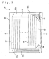
- FIG. 3 is a plan view of the confronting substrate constituting the liquid crystal device of the embodiment when it is viewed from the liquid crystal layer side.
- FIG. 4 is a partial plan view of color filters included in the liquid crystal device of the embodiment when they are viewed from the liquid crystal layer side and is a view showing the region of a color filter denoted by reference numeral 57 in FIG. 2 in enlargement.
- FIG. 5 is a sectional view showing the structure of the liquid crystal device of the embodiment and is a fragmentary sectional view of the liquid crystal device of the embodiment when it is taken along the line A - A' shown in FIGS. 2 and 3.
- a color filter substrate 10 and a confronting substrate 20 acting as a pair of substrates are bonded to each other at a predetermined interval through a seal member 40, and a liquid crystal layer 30 is enclosed inside the seal member 40.
- a display region 51 is located inside the inner end surface of the seal member 40, and the outside of the display region 51 is arranged as a non-display region.
- the seal member 40 is annularly formed between the peripheral edges of the color filter substrate 10 and the confronting substrate 20, and a liquid crystal injecting hole 41 is formed through a portion of the seal member 40 so that a liquid crystal is injected therethrough.
- the liquid crystal injecting hole 41 is sealed with a seal material 42 after the liquid crystal is injected between the color filter substrate 10 and the confronting substrate 20 (into a liquid cell) therefrom.
- a backlight (light illumination means, not shown) is disposed to the confronting substrate 20 on the side not facing the color filter substrate 10, and polarizers (not shown) for permitting only specific polarized light to pass therethrough are attached to the color filter substrate 10 and the confronting substrate 20 on their sides not facing the liquid crystal layer 30, respectively. Then, the light outgoing from the backlight sequentially passes through the polarizers on the confronting substrate 20, the confronting substrate 20, the liquid crystal layer 30, the color filter substrate 10, and the polarizers on the color filter substrate 10 and enters observer's eyes.
- the lower end of the color filter substrate 10 shown in the figure is located outside the confronting substrate 20, and an externally connecting terminal section (not shown), which is described later, is disposed to the portion of the color filter substrate 10 located outside the confronting substrate 20.
- the color filter substrate 10 is schematically arranged by sequentially laminating color filters 12 each composed of colored portions 12R, 12G, and 12B in a predetermined pattern, an overcoat layer 13 for protecting the color filters 12 as well as for flattening the surface of a substrate main body 11 on which the color filters 12 are formed, transparent electrodes 14 for applying a voltage to the liquid crystal layer 30, and an orientation film 15 for regulating the orientation of the liquid crystal molecules in the liquid crystal layer 30 on the surface of the substrate main body 11 on the liquid crystal layer 30 side thereof.
- a light shielding layer 12X and a resin member 12Y (bank) are formed at least between the adjacent colored portions 12R - 12B.
- the confronting substrate 20 is schematically arranged by sequentially laminating transparent electrodes 22 for applying a voltage to the liquid crystal layer 30 and an orientation film 23 for regulating the orientation of the liquid crystal molecules in the liquid crystal layer 30 on the surface of a substrate main body 21 on the liquid crystal layer 30 side thereof.
- the substrate main bodies 11 and 21 are composed of a light-transmisive substrate such as a glass and a transparent resin
- the overcoat layer 13 is composed of an organic film, and the like
- the transparent electrodes 14 and 22 are composed of a transparent conductive material such as an indium tin oxide, respectively.
- the orientation films 15 and 23 are composed of a polyimide film, and the like the surface of which has been subjected to rubbing.
- a multiplicity of spherical spacers 31 composed of silicon dioxide, a resin, and the like are interposed between the color filter substrate 10 and the confronting substrate 20 (in the liquid crystal layer 30) to provide a uniform cell gap.
- the seal member 40 is omitted althought it is formed at the peripheral edges of the color filter substrate 10 and the confronting substrate 20 outside the display region 51.
- the plurality of transparent electrodes 14 and 22 are disposed on the color filter substrate 10 and the confronting substrate 20 in a stripe shape, and the respective transparent electrodes 14 and the respective transparent electrodes 22 extend in directions where they intersect with each other.
- the embodiment will be described as to a case in which the transparent electrodes 14 extend in a vertical direction on the figure and the transparent electrodes 22 extend in a lateral direction thereon.
- Lead wirings 14a and 22a are connected to one ends of the transparent electrodes 14 and 22 formed in the display region 51. These lead wirings 14a and 22a are disposed outside the display region 51 (that is, in a non-display region) on the surfaces of the color filter substrate 10 and the confronting substrate 20.
- the lead wirings 14a are connected to the lower ends of the transparent electrodes 14 in the figure and disposed in the lower region of the display region 51 in the figure.
- the region in which the lead wirings 14a are disposed is referred to as a lead wiring region (lead wiring forming region) 52.
- the lead wirings 22a are connected to the left ends or the right ends of the transparent electrodes 22 on the figure and disposed in the two regions, that is, in the right and left regions of the display region 51 on the figure.
- the regions in which the lead wirings 22a are disposed are referred to as lead wiring regions 53a and 53b.
- the externally connecting terminal section is disposed only on the color filter substrate 10 in the embodiment as described above.
- an externally connecting terminal section 54 for the lower electrodes (14) is disposed at the center of an end of the color filter substrate 10
- externally connecting terminal sections 55 for the upper electrodes (21) are disposed on both the sides thereof.
- the upper electrode externally connecting terminal sections 55 are disposed separately at the two positions in correspondence to the lead wiring regions 53a and 53b.
- the lead wirings 14a are electrically connected to the lower electrode externally connecting terminal section 54, and the transparent electrodes 14 are electrically connected to the externally connecting terminal section 54 through the lead wirings 14a.
- the lead wirings 22a are connected to vertically conducting sections 56 formed by enclosing conductive particles in a part of the seal member 40.
- the vertically conducting sections 56 are disposed at two positions in correspondence to the lead wiring regions 53a and 53b, and the respective vertically conducting sections 56 are electrically connected to the upper electrode externally connecting terminal section 55 disposed to the color filter substrate 10.
- the transparent electrodes 22 are electrically connected to the externally connecting terminal section 55 through the lead wirings 22a and the vertically conducting sections 56.
- the transparent electrodes 14 and 22 are driven by directly mounting driving ICs (integrated circuits), which supplies signals to the transparent electrodes 14 and 22, on the externally connecting terminal section 54 and 55 or by electrically connecting a flexible printed circuit, on which the driving ICs for supplying signals to the transparent electrodes 14 and 22 are mounted, to the externally connecting terminal section 54 and 55.
- driving ICs integrated circuits
- the wiring structure of the lead wirings 14a and 22a and the connecting structure of the lead wirings 14a and 22a to the externally connecting terminal section 54 and 55 are not limited to the illustrated ones and may be appropriately designed. Further, while the embodiment is described as to a so-called vertically conducting type in which the externally connecting terminal sections are disposed only to one of the substrates, it is also possible to provide the externally connecting terminal sections with the respective substrates and to electrically connecting the transparent electrodes formed on each substrate to the same substrate through lead wirings.
- the respective transparent electrodes 14 on the color filter substrate 10 and the respective transparent electrodes 22 on the confronting substrate 20 extend in the directions that intersect each other. Then, in the liquid crystal device 1 of the embodiment, the regions, where the respective transparent electrodes 14 intersect the respective transparent electrodes 22, form respective pixels, and each of the color filters 12 has red (R), green (G), and blue (B) colored portions 12R, 12G, and 12B formed thereto in a predetermined pattern, corresponding to each pixel.
- color filters 12 are formed in the display region 51 which is located at least inside the inner end surface of the seal member 40, there are a case in which they are formed only in the display region 51 and a case in which they are additionally formed outside the display region 51 by several pixels. In this embodiment, the case in which the color filters 12 are additionally formed outside the display region 51 as shown in FIG. 5 will be described. Further, hereinafter, the region where color filters 12 (colored portions 12R, 12G, and 12B) are formed will be referred to as a color filter forming region 50.
- the width of the colored portions 12R to 12B is shown in enlargement in the figure, actually, the width of them is very minute and set to about 0.15 to 0.3 mm, whereas the interval between the inner end surface of the seal member 40 and the display region 51 or the color filter forming region 50 is set to about 0.2 to 3 mm which is larger than the width of the colored portions 12R to 12B. Accordingly, the color filter forming region 50 is also located inside the inner end surface of the seal member 40 similarly to the display region 51.
- the light shielding layer (black matrix) 12X is formed between the adjacent pixels (the adjacent colored portions 12R - 12B) in the color filter forming region 50.
- the colored portions 12R - 12B are formed using the inkjet method, and, in the color filter forming region 50, the resin member 12Y is formed on the light shielding layer 12X to partition the pixels, in which the respective colored portions 12R - 12B are formed, when the colored portions 12R - 12B are formed.
- the height of the resin member 12Y is about 1 - 3 ⁇ m, while the light shielding layer 12X has a film thickness of about 0.1 - 1.5 ⁇ m.
- the total height of the light shielding layer 12X and the resin member 12Y is about 1.1 - 4.5 ⁇ m, which may not be negligible with respect to the cell gap (several microns - 10 ⁇ m).
- colored inks of red, green, and blue are ejected from inkjet nozzles.
- the viscosity of the inks must be set to a low level to permit ink droplets to be continuously ejected from the inkjet nozzles without clogging the nozzles with the ink droplets. Therefore, a predetermined amount of a solvent must be blended with the inks to be used to reduce the viscosity thereof.
- the inks are ejected into the respective pixels surrounded by the resin member 12Y such that the height of them is higher than the highest portion of the resin member 12Y, the volume of the inks is reduced in the process for drying the ejected inks and removing the solvent, thereby the height of the thus formed colored portions 12R - 12B is lower than the total height of the film thickness of the light shielding layer 12X and the height of the resin member 12Y by about 0.1 - 4 ⁇ m.
- the maximum height of the layer, in which the color filters 12, the light shielding layer 12X and the resin member 12Y are formed corresponds to the height of between the adjacent colored portions 12R - 12B, that is, to the height of the portion where the light shielding layer 12X overlaps the resin member 12Y.
- the constituting materials of the respective elements constituting the color filters 12 will be briefly described.
- the colored portions 12R, 12G, and 12B are formed using the colored inks of red, green, and blue, respectively.
- the light shielding layer 12X is composed of a light shielding material (material having a low light transmitting property) such as a black resin containing black particles, for example, carbon particles, and the like, a metal such as chrome, and the like, a metal compound, and so on.
- the resin member 12Y is composed of a resin, and the like having no conductivity. Note that when the resin member 12Y are composed of the light shielding material such as the black resin, and the like, the light shielding layer 12X can be omitted.
- the region where the color filters 12, the light shielding layer 12X and the resin member 12Y are formed will be described.
- the color filters 12 (colored portions 12R - 12B) are formed inside the inner end surface of the seal member 40, in the color filter forming region 50 including the display region 51.
- the light shielding layer 12X and the resin member 12Y are formed on the approximately entire surface of the color filter non-forming region (the region outside of the color filter forming region 50), as well as between the adjacent pixels (between the adjacent colored portions 12R - 12B).
- the plan structure of the color filters 12, the light shielding layer 12X, and the resin member 12Y provided with this embodiment is as shown in FIG. 4.
- the colored portions 12R - 12B constituting the color filters 12 are disposed in a matrix shape in correspondence to the respective pixels disposed in a matrix shape, and the light shielding layer 12X and the resin member 12Y are formed between the adjacent pixels (between the adjacent colored portions 12R - 12B). Accordingly, in the color filter forming region 50 including the display region 51, the light shielding layer 12X and the resin member 12Y are formed in a lattice shape in a horizontal plane.
- the light shielding layer 12X and the resin member 12Y are formed on the approximately entire surface of the color filter non-forming region located outside the color filter forming region 50.
- the pattern of the colored portions 12R - 12B shown in FIG. 4 is only an example and the present invention is by no means limited to the pattern.
- the approximately entire surface of the color filter non-forming region specifically means “the region including the seal member 40 forming region and the lead wiring regions 52, 53a, 53b, and the like described above and excluding the region which requires a light transmitting property”.
- a region where a light transmitting property is required means, for example, portions where optically recognizable alignment marks are formed or the vicinity thereof.
- the alignment marks are disposed outside the seal member 40 forming portion as marks used when the color filter substrate 10 is bonded to the confronting substrate 20 in the manufacture of the liquid crystal device 1. Then, in the embodiment, an effect of simultaneously forming the light shielding layer 12X and the alignment marks can be also obtained by partly leaving the portions outside the seal member 40 forming region, where the light shielding layer 12X is not formed, when the light shielding layer 12X is patterned.
- the cross-shaped portion 62 can be optically read, thereby serving as an alignment mark.
- the cross-shaped portion 64 can be optically read, thereby serving as an alignment mark.
- the resin member 12Y is formed also in the seal member 40 forming region, and in manufacturing the liquid crystal device 1, the color filter substrate 10 on which necessary elements such as the color filters 12 and the transparent electrodes 14 are formed is bonded to the confronting substrate 20 on which necessary elements such as the transparent electrodes 22 are formed, through an unhardened seal member, and then the unhardened seal member is hardened while pressure is applied from the outside of the color filter substrate 10 and the confronting substrate 20, to form the liquid cell.
- the resin member 12Y which is located just under the seal member 40 must be composed of a material having such a degree of pressure resistance as not to be deformed when the pressure is applied from the outside of the color filter substrate 10 and the confronting substrate 20.
- FIGS. 6(a) - (e) are fragmentary sectional views showing respective forming processes.
- the substrate main body 11 is prepared, and the light shielding layer 12X having the pattern as shown in FIGS. 4 and 5 is formed on the entire surface of the substrate main body 11.
- the light shielding layer 12X which is composed of a black resin and has the predetermined pattern, is formed, for example, as described below.
- a negative resist mainly including a black pigment containing carbon particles, and the like, the monomer of an acrylic resin, and the like, and a polymerization initiator is coated on the entire surface of the substrate main body 11 by a spin coating method, and tentatively baked.
- the resist is exposed at predetermined positions using a photo mask on which the pattern of the light shielding layer 12X has been formed.
- the resist having been exposed is made to a resin insoluble in a solvent by the photo-polymerizing reaction of the monomer.
- the resist is developed, only the portions, which have been exposed and made insoluble in a solvent, remain, thereby forming the light shielding layer 12X having the predetermined pattern as shown in FIGS. 4 and 5.
- the light shielding layer 12X having the predetermined pattern is formed likewise even if a positive resist, which is made soluble in a solvent by being exposed, is used in place of the negative resist, which is made insoluble in a solvent by being exposed, and the portions, where the light shielding layer 12X are not formed, are exposed.
- the light shielding layer 12X which is composed of a metal such as chrome or a metal compound and has the predetermined pattern, may be formed, for example, as described below.
- the light shielding layer 12X having the predetermined pattern shown in FIGS. 4 and 5 is formed by forming a film of a metal such as chrome or a metal compound on the entire surface of the substrate main body 11 by sputtering, and the like, and then by forming the predetermined pattern by photolithography.
- a light sensitive resist for the resin member 12Y is coated on the entire surface of the substrate main body 11, on which light shielding layer 12X has been formed, by a spin coating method and the like, and exposed and developed as shown in FIG. 6(b) similarly to the case in which the light shielding layer 12X composed of the black resin, and the like is formed, thereby forming the resin member 12Y having the pattern as shown in FIGS. 4 and 5.
- the color filters 12 are formed using an inkjet method.
- an inkjet nozzle 60 is filled with a red ink 62R prepared by solving a red pigment, an acrylic resin, and the like in a solvent, and the red ink 62R is ejected from the ejection nozzles 61 of the inkjet nozzle 60 only to the pixels which form the coloring portion 12R by moving the inkjet 60 relatively to the substrate main body 11 with the ejection nozzles 61 confronting the substrate main body 11.
- the red ink 62R is ejected so that the central portion thereof is higher than the highest portion of the resin member 12Y as well as no ink leaks to the adjacent pixels.
- the red coloring portion 12R is formed, for example, by tentatively baking the red ink 62R and removing the solvent by heating the entire substrate main body 11, onto which the red ink 62R has been ejected, to about 40 - 180°C.
- the height of the thus formed coloring portion becomes lower than the highest portion of the resin member 12Y because the volume of the coloring portion is reduced by the removal of the solvent from the red ink 62R.
- the colored portions 12R - 12B having the predetermined pattern are formed by repeating the processes shown in FIGS. 6(c) and (d) as to the green colored portions 12G and the blue colored portions 12G.
- the color filters 12 composed of the colored portions 12R - 12B having the predetermined pattern, the light shielding layer 12X having the predetermined pattern, and the resin member 12Y are formed by finally baking (finally hardening) the colored portions 12R - 12B by heating the entire substrate main body 11, on which colored portions 12R - 12B have been formed, to about 150 - 270°C.
- the intimate contact property of the colored portions 12R - 12B to the substrate main body 11 is increased by finally baking the colored portions 12R - 12B, so that the exfoliation of the colored portions 12R - 12B from the substrate main body 11 is prevented in a subsequent process for forming the overcoat layer 13.
- the color filters 12 are formed in the sequence of the colored portions 12R, 12G, and 12B, they may be formed in any sequence.
- the color filter substrate 10 included in the liquid crystal device 1 of the embodiment employs such the arrangement that the light shielding layer 12X is formed on the approximately entire surface of the color filter non-forming region, in addition to the color filter forming region 50 including the display region 51. Since the area in which the colored portions 12R - 12B are formed outside the display region 51 is very small and corresponds only to several pixels, it becomes possible to shield the approximately entire surface of the non-display region from light with the light shielding layer 12X by forming it on the approximately entire surface of the color filter non-forming region.
- the light shielding layer 12X can serve as a parting member for shielding the non-display region of the liquid crystal device 1 of the embodiment from light.
- the manufacturing process of electronic equipment can be simplified by mounting the liquid crystal device 1 of the embodiment thereon because the parting member and the light shielding layer 12X are formed in one process.
- the manufacturing cost of electronic equipment is also reduced by mounting the liquid crystal device 1 of the embodiment thereon because a parting member need not be provided separately. Further, since the parting member need not be provided separately, and a margin which has been necessary due to the mounting accuracy of the parting member when it is mounted on the electronic equipment can be eliminated, an effect of increasing the area of the surface region of the electronic equipment is also obtained by mounting the liquid crystal device 1 of the embodiment.
- the color filter substrate 10 included in the liquid crystal device 1 of the embodiment further employs the arrangement such that the colored portions 12R - 12B are formed by an inkjet method, and the resin member 12Y which is formed on the substrate main body 11 around the peripheries of the respective colored portions 12R - 12B, when the colored portions 12R - 12B are formed, in order to partition the respective pixels for forming the respective colored portions 12R - 12B, are formed on the approximately entire surface of the color filter non-forming region, in addition to the color filter forming region 50 including the display region 51.
- the highest place of the color filter forming region 50in which the color filters 12, the light shielding layer 12X and the resin member 12Y are formed is between the adjacent colored portions 12R - 12B, that is, the height of the portion where the light shielding layer 12X overlaps the resin member 12Y.
- the maximum height of the color filter forming region 50 is made equal to the maximum height of the color filter non-forming region in the layer in which the color filters 12, the light shielding layer 12X, and the resin member 12Y are formed as shown in FIG. 5.
- any step between the color filter forming region 50 and the color filter non-forming region can be removed on the surfaces of the color filters 12, thereby the entire surfaces of the color filters 12 being approximately flattened.
- the surface of the color filter substrate 10 is more flattened than that of a conventional color filter substrate, so that an effect of providing a liquid crystal device excellent in display quality can be also obtained because the cell gap is uniformly arranged.
- the transparent electrodes 14 (or the lead wirings 14a) formed on the color filters 12 are prevented from being broken, thereby realizing an effect of improving the yield rate of nondefective products.
- both the light shielding layer 12X and the resin member 12Y are formed on the approximately entire surfaces of the color filter non-forming region.
- the seal member 40 is formed on the light shielding layer 12X and the resin member 12Y and the thicknesses of the light shielding layer 12X and resin member 12Y are changed without changing the thickness of the seal member 40, the cell gaps are not affected thereby at all.
- an effect of stabilizing the cell gaps is also obtained.
- the present invention is by no means limited thereto and only the resin member 12Y may be formed on the approximately entire surface of the color filter non-forming region.
- the highest portion of the color filter forming region 50 is between the adjacent colored portions 12R - 12B, that is, the portion where the light shielding layer 12X overlaps the resin member 12Y.
- the difference between maximum height of the color filter forming region 50 and that of the color filter non-forming region may be reduced in the layer in which the color filters 12, the light shielding layer 12X, and the resin member 12Y are formed by forming the resin member 12Y on the approximately entire surface of the color filter non-forming region.
- the light shielding layer 12X is not formed on the approximately entire surfaces of the color filter non-forming region.
- FIG. 8 is an exploded perspective view showing an entire structure of a liquid crystal device of this embodiment.
- the liquid crystal device of the embodiment is provided with the color filters included in the liquid crystal device of the first embodiment.
- the same components as those in the first embodiment are denoted by the same reference numerals, and the description thereof is omitted.
- description will be given to an example in which the color filter substrate is disposed on an observer side in this embodiment.
- the liquid crystal device 2 of this embodiment is approximately composed of a color filter substrate 80 and an element substrate 90 disposed in confrontation with each other with a liquid crystal layer (not shown) held therebetween.
- an end portion of the element substrate 90 is located outside the color filter substrate 80, and is provided with an externally connecting terminal section.
- the externally connecting terminal section is omitted and the color filter substrate 80 and the element substrate 90 are shown to have an same area.
- the color filter substrate 80 is bonded to the element substrate 90 at the respective peripheral edges thereof through a seal member (not shown).
- a multiplicity of data lines 92 and a multiplicity of scan lines 93 are formed on the surface of the substrate main body 91 in a lattice shape so as to intersect with each other.
- the TFT elements 94 are formed in the vicinities of the intersections of the respective data lines 92 and the respective scan lines 93, and the pixel electrodes 95 are connected through the respective TFT elements 94.
- the multiplicity of pixel electrodes 95 are disposed in a matrix shape, and the regions, in which the respective pixel electrodes 95 are formed, are arranged as respective pixels in the liquid crystal device 2.
- the respective data lines 92 and the respective scan lines 93 are electrically connected to the externally connecting terminal section (not shown) disposed to the element substrate 90 through lead wirings 92a and 93a connected to one ends thereof, respectively.
- each of the color filters 12 included in this embodiment is composed of red (R), green (G), and blue (B) colored portions 12R, 12G, and 12B formed in correspondence to each pixel in a color filter forming region 50 including a display region.
- a light shielding layer 12X and a resin member 12Y are formed between the adjacent pixels (the adjacent colored portions 12R - 12B) in the color filter forming region 50, and on the approximately entire surface of a color filter non-forming region including a seal member forming region and lead wire regions.
- the common electrode 82 is formed on the approximately entire surface of the color filter substrate 80 on the liquid crystal layer side of the color filters 12 and electrically connected to the externally connecting terminal section (not shown) disposed to the element substrate 90 through a vertically-conducting section (not shown) formed at a portion of a seal member.
- the present invention can be also applied to an active matrix type liquid crystal device using TFT elements, and the color filter substrate 80 included in the liquid crystal device 2 of this embodiment has the color filters 12, the light shielding layer 12X, and the resin member 12Y included in the liquid crystal device of the first embodiment.
- the second embodiment can obtain the same effects as those of the first embodiment.
- a manufacturing process of electronic equipment can be simplified by mounting the liquid crystal device 2 of this embodiment thereon because a parting member and the light shielding layer 12X are formed in one process, so that the manufacturing cost of the electronic equipment can be reduced as well as the area of the display region of the electronic equipment can be increased.
- the surface of the color filter substrate 80 is more flattened than that of a conventional color filter substrate and cell gaps are uniformly arranged, thereby an effect of providing a liquid crystal device excellent in display quality being also obtained. Further, since the surface of the color filter substrate 80 is more flattened than that of the conventional color filter substrate, the common electrode 82 (or the lead wirings connected to the common electrodes 82) formed on the color filters 12 can be prevented from being broken, thereby improving the yield rate of nondefective products.
- both the light shielding layer 12X and the resin member 12Y are formed on the approximately entire surface of the color filter non-forming regions.
- the seal member is formed on the light shielding layer 12X and the resin member 12Y and the thicknesses of the light shielding layer 12X and the resin member 12Y are changed without changing the thickness of the seal member, the cell gaps are not affected thereby at all.
- an effect of stabilizing the cell gaps can be also obtained.
- FIG. 9 is an exploded perspective view showing an entire structure of the liquid crystal device of the embodiment.
- the liquid crystal device of the embodiment is provided with the color filters included in the liquid crystal device of the first embodiment.
- the same components as those in the first embodiment are denoted by the same reference numerals, and the description thereof is omitted.
- a color filter substrate is disposed on an observer side similarly to the first embodiment, will be described also in this embodiment.
- the liquid crystal device 4 of this embodiment is approximately composed of a color filter substrate 100 and an element substrate 110 disposed in confrontation with each other with a liquid crystal layer (not shown) held therebetween.
- the element substrate 110 is approximately arranged such that TDF elements 114, pixel electrodes 113, and the like are formed on the surface of a substrate main body 111 on the liquid crystal layer side thereof, and an orientation film (not shown) is formed on them on the liquid crystal layer side thereof.
- the color filter substrate 100 is approximately arranged such that color filters 12, an overcoat layer (not shown), scan lines (confronting electrodes) 102, and an orientation film (not shown) are sequentially laminated on the surface of a substrate main body 101 on the liquid crystal layer side thereof.
- an externally connecting terminal section is disposed to at least one of the color filter substrate 100 and the element substrate 110, and the portion where the externally connecting terminal section is disposed is located outside the confronting substrate, similarly to the first embodiment.
- the color filter substrate 100 and the element substrate 110 are illustrated to have the same area as well as the illustration of the externally connecting terminal section is omitted for the purpose of simplification.
- the color filter substrate 100 is bonded to the element substrate 110 at the respective peripheral edges thereof through a seal member (not shown).
- a multiplicity of data lines 112 are disposed on the surface of a substrate main body 111 in a stripe shape, and a multiplicity of pixel electrodes 113 are connected to the respective data lines 112 through the TFD elements 114.
- the multiplicity of pixel electrodes 113 are disposed in a matrix shape, and the regions, in which the respective pixel electrodes 113 are formed, are arranged as respective pixels in the liquid crystal device 4.
- the respective data lines 112 are electrically connected to the externally connecting terminal section (not shown) disposed to at least one of the substrates through the lead wirings 112a connected to one ends of the data lines 112.
- each of the color filters 12 is composed of red (R), G (green), and B (blue) colored portions 12R - 12B formed in correspondence to each pixel in a color filter forming region 50 including a display region.
- a light shielding layer 12X and a resin member 12Y are formed between the adjacent pixels (the adjacent colored portions 12R - 12B) in the color filter forming region 50 and on the approximately entire surface of a color filter non-forming region including a seal member forming region and lead wire regions on the surface of the color filter substrate 80.
- the strip-shaped scan lines (confronting electrodes) 102 are formed on the liquid crystal layer side of the color filters 12 in a direction intersecting the direction in which the data lines 112 of the element substrate 110 extend.
- the scan lines 102 are also electrically connected to the externally connecting terminal section (not shown) disposed to at least one of the substrates through the lead wirings (not shown) connected to one ends of the scan lines 102.
- the present invention can be also be applied to an active matrix type liquid crystal device using TFD elements, and the color filter substrate 100 included in the liquid crystal device 4 of this embodiment has the color filters 12, the light shielding layer 12X, and the resin member 12Y which are included in the liquid crystal device of the first embodiment.
- the third embodiment can obtain the same effects as those of the first embodiment.
- a manufacturing process of electronic equipment can be simplified by mounting the liquid crystal device 4 of the embodiment thereon because a parting member and the light shielding layer 12X are formed in one process, so that the manufacturing cost of the electronic equipment can be reduced as well as the area of the display region of the electronic equipment can be increased.
- the surface of the color filter substrate 100 can be more flattened than the surface of a conventional color filter substrate and cell gaps can be uniformly arranged, thereby realizing an effect of providing a liquid crystal device excellent in display quality. Further, since the surface of the color filter substrate 100 can be more flattened than the surface of the conventional color filter substrate, scan lines 102 (or the lead wirings connected to the scan lines 102) formed on the color filters are prevented from being broken, thereby realizing an effect of improving the yield rate of nondefective products.
- both the light shielding layer 12X and the resin member 12Y are formed on the approximately entire surface of the color filter non-forming region.
- the seal member is formed on the light shielding layer 12X and the resin member 12Y and the thicknesses of the light shielding layer 12X and the resin member 12Y are changed without changing the thickness of the seal member, the cell gaps are not affected thereby at all.
- an effect of stabilizing the cell gaps is also obtained.
- the present invention is by no means limited thereto, and the color filter substrate side may be located on a light incident side. Similar effects to those of the first to third embodiments can be also be obtained in this case.
- a transmissive liquid crystal device has been described in the first to third embodiments, the present invention is by no means limited thereto, and the present invention is also applicable to a reflective liquid crystal device and a reflective/semi-transmissive liquid crystal device, that is, it is applicable to a liquid crystal device of any structure.
- This embodiment shows an example in which the present invention is applied to an active matrix type organic EL device (electrooptical device) using electroluminescence elements as pixels.
- a first composition which contains a positive hole injection layer forming material, or a second composition, which contains a light emitting layer forming material, is formed by an inkjet method. That is, the first composition containing the positive hole injection layer material dissolved or dispersed in a solvent or the second composition containing the light emitting material dissolved or dispersed in a solvent is ejected from an inkjet head and formed on electrodes composed of ITO (transparent electrodes).
- partitions hereinafter, referred to as banks
- partitioning pixel regions where the ITO is formed are provided so that the ejected ink droplets (liquid droplets)can accurately pattern-coat the predetermined pixel regions.
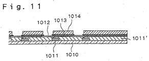
- FIG. 11 shows a sectional view of an example of a substrate structure of the organic EL device formed by an inkjet method.
- a circuit element portion 1011' having thin film transistors (TFTs) 1011 are formed on a glass substrate 1010, and transparent electrodes 1012 composed of an ITO are patterned on the circuit element portion 1011'.
- a first bank 1013 composed of SiO2 and an organic material bank (second bank) 1014 composed of an organic material which is ink-repellent or arranged to have ink-repellency are laminated on each of the regions for partitioning the transparent electrodes 1012.
- the opening of the banks may have any of a circular shape, an oval shape, and a square shape
- the openings having the square shape are preferably rounded at the corners thereof because the ink composition has a surface tension.
- the material of the organic material bank 1014 is not particularly limited so long as it is excellent in heat resistance, liquid repellency, ink solvent resistance, and adhesion to a base substrate.
- the organic material bank 1014 need not be composed of a material having liquid-repellency by nature, for example, a fluorine resin and may be composed of an ordinarily employed organic resin such as an acrylic resin, a polyimide resin, etc.
- the banks are not limited to the laminated inorganic and organic materials as described above.
- the organic material banks 1014 are composed of the ITO, it is preferable to provide SiO2 banks 1013 to improve the adhesion to the organic material banks 1014.
- the organic material banks 1014 preferably have a height of about 1 - 2 ⁇ m.
- a solution (a first composition) containing the positive hole injection layer forming material is coated on a substrate having a bank structure as liquid droplets by an inkjet method.
- a solution (an ink composition) containing the organic EL element (light-emitting layer forming material) is coated as ink droplets.
- an organic EL thin film is formed.
- the first composition containing the positive hole injection layer forming material and the second composition 1015 containing the organic EL material are ejected from an inkjet head 1016 and reached as shown in FIG. 12(B) so that they are pattern coated.
- each of the organic EL thin film layers 1017 is a laminated film composed of, for example, a positive hole injection layer and a light-emitting layer.
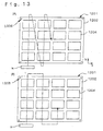
- FIG. 13 shows a plan view of a substrate employed in this embodiment.
- the substrate 1201 is mainly composed of a not shown circuit element portion formed on a glass substrate 1202, a plurality of light-emitting elements 1204 ... formed on the circuit element portion, and alignment marks 1205.
- 16 pieces of the light-emitting elements 1204 ... are disposed on a matrix of 4 columns by 4 rows.
- the organic material banks 1014 are formed between the respective light-emitting elements 1204 ... on the glass substrate 1202. Further, the alignment marks 1205 and the organic material banks 1014 can be simultaneously patterned. This makes the number of processes and the manufacturing cost reduced.
- the inkjet head H pattern coats the organic EL material ink composition 1015 on the substrate by moving relatively to the substrate as shown by broken lines of FIG. 13.
- the banks are formed up to the ends of the substrate (refer to FIG. 11).
- the formation of the banks up to the ends permits the banks to have surfaces with high flatness. Accordingly, ones of the electrodes (for example, cathodes) constituting the organic EL elements are not broken or no pinhole is formed.
- a seal structure excellent in flatness is obtained because the substrate has high flatness over the entire surface thereof. That is, an approximately flat layer can be formed on the organic EL elements in a can seal in which the organic EL elements are sealed by a can structure, in an entire seal in which a resin is coated on the entire surfaces of the organic EL elements, and in an thin film seal in which thin films are laminated.
- a uniform display is obtained without optical difference over the entire surface of the substrate because the surface of the organic EL elements is flat over the entire surface of the substrate. If the thickness of the layer between the organic EL elements and the sealing substrate is not uniform, an uneven display is executed due the occurrence of an optical difference caused by the difference in a film thickness.
- a bonding (sealing) resin can be formed flatly on the organic EL elements because a resin layer is formed over the entire surface of the substrate. Accordingly, no optical difference is caused in the sealing resin, so that no unevenness is caused in display characteristics.
- FIG. 14(a) is a perspective view showing an example of a mobile phone.
- reference numeral 700 denotes a mobile phone main body
- reference numeral 701 denotes a display unit using any one of the electrooptical devices 1 - 4.
- FIG. 14(b) is a perspective view showing an example of a mobile information processing apparatus such as a word processor and a personal computer.
- reference numeral 800 denotes an information processing apparatus
- reference numeral 801 denotes an input unit such as a keyboard
- reference numeral 803 denotes an information processing apparatus main body
- reference numeral 802 denotes a display unit using any one of the electrooptical devices 1 - 4.
- FIG. 14(c) is a perspective view showing an example of wrist watch type electronic equipment.
- reference numeral 900 denotes a watch main body
- reference numeral 901 denotes a display unit using any one of the electrooptical devices 1 - 4.
- the electronic equipment shown in FIG. 14(a) - (c) includes the display unit using any one of the electrooptical devices 1 - 4, the manufacturing process thereof is simplified and the manufacturing cost thereof is reduced as well as the electronic equipment is provided with a display region whose area is increased or the electronic equipment is excellent in display quality and has an improved yield rate of nondefective products.
- the resin layer having a light shielding property is formed on the approximately entire surface of the color filter non-forming region, in addition to the display region and further the alignment marks are composed of the resin material, the parting member, the light shielding layer, and the alignment marks are formed in one process. Accordingly, the manufacturing process of the electronic equipment is simplified by mounting the liquid crystal device including the first color filter substrate of the present invention thereon, thereby the manufacturing cost of the electronic equipment is reduced and the area of the display region of the electronic equipment is increased.
- the surface of the color filter substrate is more flattened than that of the conventional color filter substrate.
- the colored portions constituting each color filter are formed by an inkjet system as well as the resin material, which partitions the portions where the colored portions are formed, is formed on the approximately entire surface of the color filter non-forming region when the colored portions are formed, in addition along the peripheries of the respective colored portions. Accordingly, the cell gaps are uniformly arranged and the liquid crystal device excellent in display quality is provided by arranging the liquid crystal device using the second color filter substrate of the present invention.
- the surface of the color filter substrate is more flattened than that of the conventional color filter substrate, the electrodes, the wirings, and the like formed on the color filters are prevented from being broken, thereby improving the yield rate of nondefective products.
- the alignment marks are composed of the resin material, the inter-pixel partition members and the alignment marks are formed in one process. Accordingly, the manufacturing process of the electronic equipment is simplified by mounting the liquid crystal device including the second color filter substrate of the present invention thereon, thereby the manufacturing cost of the electronic equipment is reduced and the area of the display region of the electronic equipment is increased.
- the organic material banks and the alignment marks are composed of resin material, the organic material banks and the alignment marks are formed in the same process.
- the manufacturing process of the electronic equipment is simplified and the manufacturing cost thereof is reduced by mounting the liquid crystal device including the electroluminescence substrate of the present invention thereon.
- the electrooptical device of the present invention can be provided by using the first or second color filter substrate or the electroluminescence substrate of the present invention.
- the electronic equipment of the present invention may be provided by using the electrooptical device of the present invention. Then, according to the electrooptical device and the electronic equipment of the present invention, similar effects are obtained to those of the first or second color filter substrate and the electroluminescence substrate of the present invention.
Abstract
Description
- The present invention relates to a color filter substrate having color filters on a substrate main body, an electroluminescence substrate having electroluminescence elements on a substrate main body, and an electrooptical device having the color filter substrate or the electroluminescence substrate as well as to electronic equipment having the electrooptical device.
- A liquid crystal device used as a direct viewing type display device, and the like mounted on electronic equipment such as a mobile phone is mainly composed of a pair of substrates disposed in confrontation with each other with a liquid crystal layer held therebetween and having electrodes for applying a voltage to the liquid crystal layer. Further, a liquid crystal device having color filters disposed on one of substrates to perform a full color display has been widely used.
- An example of a conventional liquid crystal device having color filters will be explained as to a passive matrix type transmissive liquid crystal device based on FIG. 10. FIG. 10 is a fragmentary sectional view showing a structure of the conventional liquid crystal device.
- The conventional transmissive liquid crystal device shown in FIG. 10 is schematically arranged such that a
color filter substrate 200 and a confrontingsubstrate 300, which act as a pair of substrates, are disposed in confrontation with each other with aliquid crystal layer 400 held therebetween, and thecolor filter substrate 200 is bonded to the confrontingsubstrate 300 at the respective peripheral edges thereof through aseal member 500. - The
color filter substrate 200 is schematically arranged such thatcolor filters 220, anovercoat layer 230,transparent electrodes 240, and anorientation film 250 are sequentially laminated on the surface of a substratemain body 210 on theliquid crystal layer 400 side thereof, and the confrontingsubstrate 300 is schematically arranged such thattransparent electrodes 320 and anorientation film 330 are sequentially laminated on the surface of a substratemain body 310 on theliquied crystal layer 400 side thereof. - The plurality of
transparent electrodes 240 are disposed on thecolor filter substrate 200 and the plurality oftransparent electrodes 320 are disposed on the confrontingsubstrate 300 in a stripe shape, and the respectivetransparent electrodes 240 and the respectivetransparent electrodes 320 extend in directions which intersect each other. Then, the regions, where the respectivetransparent electrodes 240 intersect the respectivetransparent electrodes 320, are arranged as respective pixels, and eachcolor filter 220 has red (R), green (G), and blue (B) coloredportions light shielding layers 220X are formed between the adjacent pixels on thecolor filter substrate 200. - While the
color filters 220 are formed in a display region 610 located at least inside the inner end surface of theseal member 500, there are a case in which they are formed only in the display region 610 and a case in which they are additionally formed outside the display region 610 by several pixels. FIG. 10 shows the case in which thecolor filters 220 are additionally formed outside the display region 610 by the several pixels. Further, a color filter forming region is denoted byreference numeral 600. Note that, while the width of thecolored portions 220R to 220B is shown in enlargement in the figure, actually, the width of them is very minute and set to about 0.15 to 0.3 mm, whereas the interval between the inner end surface of theseal member 500 and the display region 610 or the colorfilter forming region 600 is set to about 0.2 to 3 mm which is relatively larger than the width of thecolored portions 220R to 220B. - Accordingly, in the conventional transmissive liquid crystal device, a region where the
color filters 220 are not formed inevitably exists at the peripheral edge of the region, which is located inside theseal member 500 and in which theliquid crystal layer 400 is enclosed, not only in the case in which thecolor filters 220 are formed only in the display region 610 but also in the case in which thecolor filters 220 are additionally formed outside the display region 610 by the several pixels. Thus, as shown in the figure, a step, which corresponds to the height (0.7 to 3 µm) of thecolor filters 220, is formed on the surface of thecolor filter substrate 200 along the boundary between the colorfilter forming region 600 and the color filter non-forming region (outside the forming region 600). - In contrast, recently, there have been developed technologies for an electroluminescence device acting as a display device making use of electroluminescence elements. With respect to an organic electroluminescence (referred to as EL throughout this description) element using an organic material as a light emitting material, there have been mainly reported a method of forming a low molecular organic EL element (light emitting material) to a film by vapor deposition as shown on page 913 of Appl. Phis. Lett. 51(12), September 21, 1987 and a method of coating a high molecular organic EL element as shown on page 34 of Appl. Phys. Lett. 71(1), July 7, 1997.
- As a coloring means, a method of vapor depositing different light emitting materials on desired pixels through a mask is executed in the low molecular material. In contrast, as to the high molecular material, attention is paid to colorization by minute patterning using an inkjet method. The following examples are known as to the formation of organic EL elements using an inkjet method. That is, they are Japanese Unexamined Patent Application Publications Nos. 7-235378, 10-12377, 10-153967, 11-40358, 11-54270, 3-39957, and USP 6087196.
- Incidentally, in general, when a display device such as a liquid crystal device and an organic EL element is mounted on electronic equipment such as a mobile phone, the display screen of the electronic equipment is set about 0.5 to 3 mm wider than the display region of the display device so that a display is performed without any problem even if the display region of the display device is somewhat dislocated from the display screen of the electronic equipment exposed from the window of the case of the electronic equipment.
- Accordingly, when the display device is mounted on the electronic equipment such as a mobile phone, the non-display region of the display device which is located in the vicinity of display region, is located in the vicinity of the peripheral edge of the display screen. Thus, a parting member for shielding the non-display region from light is attached to the electronic equipment having the display device mounted thereof to prevent the non-display region of the display device from being observed by an observer. As described above, since the parting member is conventionally disposed independently of the other elements constituting the display device, a process for attaching the parting member is required additionally, from which a problem is arisen in that the number of the processes for manufacturing the electronic equipment is increased.
- Further, the parting member is made by coating a black pigment on a resin molded member. However, since a cost for coating the black pigment on the resin molded member is expensive, a problem is arisen in that the manufacturing cost of the electronic equipment is increased.
- Further, since a mounting accuracy is limited when the parting member is attached to the electronic equipment, a margin of about ± 0.1 to 2 mm must be provided so that display is performed without any problem even if the inner end of the parting member is somewhat dislocated from the outer end of the display region of the display device, from which a problem is arisen in that the area of the display region of the electronic equipment (display device) is reduced by the margin.
- Further, as described above, the step corresponding to the height of the color filters is formed on the surface of the color filter substrate constituting the conventional liquid crystal device shown in FIG. 10 along the boundary between the color filter forming region and the color filter non-forming region. Therefore, in the region which is located inside of the seal member and in which the liquid crystal layer is enclosed, the cell gap of the color filter non-forming region is larger than the cell gap of the color filter forming region including the display region by the step. The cell gap of the display region is about several microns - 10 µm, whereas the thickness of the color filters is about 0.7 to 3 µm. Accordingly, the difference between the cell gap in the color filter forming region and the cell gap in the color filter non-forming region is not negligible. Thus, there is also a problem that the height of the seal depends on the thickness of the color filters.
- In a liquid crystal device using an STN (super twisted nematic) type liquid crystal, a light transmittance varies in accordance with the change of a Δn · d value (where, Δn shows the double refraction factor of a liquid crystal, and d shows a cell gap). Thus, when there is a difference in the cell gap between the color filter forming region and the color filter non-forming region, different light transmittances are exhibited in these regions. While a color filter non-forming region belongs to the non-display region, there is a possibility that the light transmittance of the color filter non-forming region slightly affects the light transmittance of the peripheral edge of the display region, that is, the display region which is located in the vicinity of the non-display region. Then, when the light transmittance of the color filter non-forming region affects the light transmittance of the peripheral edge of the display region, the brightness of the peripheral edge of the display region is changed. Thus, there is a possibility that a contract is reduced and display quality is deteriorated.
- It should be noted that while the above problems are particularly outstanding in a passive matrix type liquid crystal device in which light transmittance is greatly affected by cell gaps, they may occur in any liquid crystal devices.
- The transparent electrodes are formed on the color filter in the color filter substrate constituting the conventional liquid crystal device shown in FIG. 10. However, since the thickness of the transparent electrodes is as thin as about 0.1 to 0.2 µm, when a step is formed between the color filter forming region and the color filter non-forming region on the surface of the color filter substrate, there is also a possibility that the transparent electrodes (or lead wirings connected to one ends of the transparent electrodes) are broken at the step.
- Note that while the electrodes are formed on the color filters in a passive matrix type liquid crystal device as shown in FIG. 10, wirings such as data lines and scan lines instead of the electrodes may be formed on the color filters in an active matrix type liquid crystal device using TFT elements and TFD elements as switching elements. In this case, there is also a possibility that the wirings such as data lines and scan lines (or lead wirings connected to the one ends of the wirings such as data lines and scan lines) are broken at the step.
- The above problems caused by the step formed between the color filter forming region and the color filter non-forming region can be eased by reducing the thickness of the color filters. However, when the thickness of the color filters is reduced, the concentration of coloring materials contained in colored portions must be increased. However, the reduction of the thickness of the color filters is difficult because it is technically difficult to thinly and uniformly coat a resist of high concentration.
- Further, alignment marks, which are used when the color filters or the organic EL elements are made by an inkjet method, must be formed separately from inter-pixel partition members, from which a problem is arisen in that the number of processes is increased.
- The present invention was made in view of the above circumstances, and a first object of the present invention is to provide a means capable of forming a parting member and the other components constituting a display device in one process and reducing a manufacturing cost of electronic equipment as well as increasing the area of the display region of the electronic equipment. A second object of the present invention is to provide a means capable of more flattening the surface of a color filter substrate than that of a conventional color filter substrate and arranging cell gaps uniformly as well as preventing electrodes, wirings, and the like formed on color filters from being broken. A third object of the present invention is to provide a means capable of reducing the number of processes by forming alignment marks simultaneously with the patterning of partition members.
-
- FIG. 1 is a plan view of a transmissive liquid crystal device of a first embodiment according to the present invention when it is viewed from a confronting substrate side.
- FIG. 2 is a plan view of a color filter substrate constituting the transmissive liquid crystal device of the first embodiment according to the present invention when it is viewed from a liquid crystal layer side.
- FIG. 3 is a plan view of the confronting substrate constituting the transmissive liquid crystal device of the first embodiment according to the present invention when it is viewed from the liquid crystal layer side.
- FIG. 4 is a partial plan view of color filters included in the transmissive liquid crystal device of the first embodiment according to the present invention when they are viewed from the liquid crystal layer side.
- FIG. 5 is a partial sectional view showing a structure of the transmissive liquid crystal device of the first embodiment according to the present invention.
- FIGS. 6(a) to (e) are process views showing a method of forming the color filters, light shielding layers, and resin members included in the transmissive liquid crystal device of the first embodiment according to the present invention.
- FIGS. 7(a), (b) are enlarged plan views showing a corner portion of the color filter substrate included in the transmissive liquid crystal device of the first embodiment according to the present invention.
- FIG. 8 is an exploded perspective view showing a structure of a transmissive liquid crystal device of a second embodiment according to the present invention.
- FIG. 9 is an exploded perspective view showing a structure of a transmissive liquid crystal device of a third embodiment according to the present invention.
- FIG. 10 is a sectional view showing a structure of a conventional transmissive liquid crystal device.
- FIG. 11 is a sectional view showing an example of a method of manufacturing an organic EL device by an inkjet system.
- FIG. 12 is a sectional view showing an example of a method of manufacturing an organic EL device by an inkjet system according to the present invention.
- FIGS. 13(A) and (B) are schematic views explaining a method of manufacturing an organic EL device of an embodiment 4 and show the loci of an inkjet head, and alignment marks on the substrate.
- FIG. 14(a) is a view showing an example of a mobile phone including a transmissive liquid crystal device of any of the above embodiments, FIG. 14(b) is a view showing an example of a mobile information processing apparatus including a transmissive liquid crystal device of any of the above embodiments, and FIG. 14(c) is a view showing an example of a wrist watch type electronic equipment including a transmissive liquid crystal device of any of the above embodiments.
-
- To solve the above problems, the present invention provides an electrooptical device composed of a pair of confronting substrates having electrodes on the inner surfaces of the substrates and an electrooptical material held therebetween, wherein the pair of substrates are bonded by a seal formed on the inner surfaces of the substrates, and at least one of the pair of substrates is a color filter substrate having a plurality of color filters formed in a region surrounded by a seal portion in which the seal is formed,
the electrooptical device is characterized in that a resin film is formed on the substrate described above in the region where the seal portion is formed, as well as in the region surrounding the entire peripheries of the color filters. - Further,
- (1) the color filter substrate has alignment marks formed of the resin film;
- (2) the resin film has a film thickness from 0.5 µm to 5 µm;
- (3) the resin film is provided to partition the sections in which respective color filter portions are formed when the color filters are formed by an inkjet method;
- (4) the resin film is formed of a material having liquid repellency with respect to a liquid material that forms the color filters;
- (5) the resin film is formed of a material having a light shielding property;
- (6) the resin film is formed of a material having an electric insulating property;
- (7) the seal is formed of a material containing particles for keeping a gap between the pair of substrates constant and an adhesive for bonding the pair of substrate; and
- (8) electronic equipment is characterized by being provided with the electrooptical device. Further, the present invention provides an electrooptical device composed of electroluminescence elements on a substrate, each having a light emitting layer between electrodes,
-
- Next, the embodiments according to the present invention will be described in detail. Note that while the respective embodiments are described with reference to the figures, respective layers and respective components are shown by a different reduction scale in the respective figures so that they are shown in recognizable sizes on the figures.
- A structure of an electrooptical device of a first embodiment according to the present invention will be described.
- This embodiment shows an example in which the present invention is applied to a passive matrix type transmissive liquid crystal device acting as an electrooptical device. The liquid crystal device of this embodiment is provided with a color filter substrate of the present invention and has a feature in the structure of color filters. Note that, in this embodiment, description is given of the case, for example, in which the color filter substrate is disposed on an observer side.
- A structure of the liquid crystal device of this embodiment will be described below based on FIGS. 1 - 5. FIG. 1 is a plan view of the liquid crystal device of the embodiment when it is viewed from the side of a confronting substrate which will be described later. FIG. 2 is a plan view of the color filter substrate constituting the liquid crystal device of the embodiment when it is viewed from a liquid crystal layer side. FIG. 3 is a plan view of the confronting substrate constituting the liquid crystal device of the embodiment when it is viewed from the liquid crystal layer side. FIG. 4 is a partial plan view of color filters included in the liquid crystal device of the embodiment when they are viewed from the liquid crystal layer side and is a view showing the region of a color filter denoted by
reference numeral 57 in FIG. 2 in enlargement. FIG. 5 is a sectional view showing the structure of the liquid crystal device of the embodiment and is a fragmentary sectional view of the liquid crystal device of the embodiment when it is taken along the line A - A' shown in FIGS. 2 and 3. - As shown in FIG. 1, in the
liquid crystal device 1 of the embodiment, acolor filter substrate 10 and a confrontingsubstrate 20 acting as a pair of substrates are bonded to each other at a predetermined interval through aseal member 40, and aliquid crystal layer 30 is enclosed inside theseal member 40. In theliquid crystal device 1, adisplay region 51 is located inside the inner end surface of theseal member 40, and the outside of thedisplay region 51 is arranged as a non-display region. - The
seal member 40 is annularly formed between the peripheral edges of thecolor filter substrate 10 and the confrontingsubstrate 20, and a liquid crystal injecting hole 41 is formed through a portion of theseal member 40 so that a liquid crystal is injected therethrough. The liquid crystal injecting hole 41 is sealed with aseal material 42 after the liquid crystal is injected between thecolor filter substrate 10 and the confronting substrate 20 (into a liquid cell) therefrom. - Further, a backlight (light illumination means, not shown) is disposed to the confronting
substrate 20 on the side not facing thecolor filter substrate 10, and polarizers (not shown) for permitting only specific polarized light to pass therethrough are attached to thecolor filter substrate 10 and the confrontingsubstrate 20 on their sides not facing theliquid crystal layer 30, respectively. Then, the light outgoing from the backlight sequentially passes through the polarizers on the confrontingsubstrate 20, the confrontingsubstrate 20, theliquid crystal layer 30, thecolor filter substrate 10, and the polarizers on thecolor filter substrate 10 and enters observer's eyes. - Further, the lower end of the
color filter substrate 10 shown in the figure is located outside the confrontingsubstrate 20, and an externally connecting terminal section (not shown), which is described later, is disposed to the portion of thecolor filter substrate 10 located outside the confrontingsubstrate 20. - Next, the internal structure of the
liquid crystal device 1 of the embodiment will be described in detail. - As shown in FIG. 5, the
color filter substrate 10 is schematically arranged by sequentially laminatingcolor filters 12 each composed ofcolored portions overcoat layer 13 for protecting thecolor filters 12 as well as for flattening the surface of a substratemain body 11 on which thecolor filters 12 are formed,transparent electrodes 14 for applying a voltage to theliquid crystal layer 30, and anorientation film 15 for regulating the orientation of the liquid crystal molecules in theliquid crystal layer 30 on the surface of the substratemain body 11 on theliquid crystal layer 30 side thereof. Further, in thecolor filter substrate 10, alight shielding layer 12X and aresin member 12Y (bank) are formed at least between the adjacentcolored portions 12R - 12B. - In contrast, the confronting
substrate 20 is schematically arranged by sequentially laminatingtransparent electrodes 22 for applying a voltage to theliquid crystal layer 30 and anorientation film 23 for regulating the orientation of the liquid crystal molecules in theliquid crystal layer 30 on the surface of a substratemain body 21 on theliquid crystal layer 30 side thereof. - Here, the substrate
main bodies overcoat layer 13 is composed of an organic film, and the like, and thetransparent electrodes orientation films - Further, a multiplicity of
spherical spacers 31 composed of silicon dioxide, a resin, and the like are interposed between thecolor filter substrate 10 and the confronting substrate 20 (in the liquid crystal layer 30) to provide a uniform cell gap. - Next, the plan structure of the
transparent electrodes transparent electrodes seal member 40 is omitted althought it is formed at the peripheral edges of thecolor filter substrate 10 and the confrontingsubstrate 20 outside thedisplay region 51. - As shown in FIGS. 2 and 3, the plurality of
transparent electrodes color filter substrate 10 and the confrontingsubstrate 20 in a stripe shape, and the respectivetransparent electrodes 14 and the respectivetransparent electrodes 22 extend in directions where they intersect with each other. The embodiment will be described as to a case in which thetransparent electrodes 14 extend in a vertical direction on the figure and thetransparent electrodes 22 extend in a lateral direction thereon. -
Lead wirings transparent electrodes display region 51. Theselead wirings color filter substrate 10 and the confrontingsubstrate 20. - As shown in FIG. 2, on the
color filter substrate 10, thelead wirings 14a are connected to the lower ends of thetransparent electrodes 14 in the figure and disposed in the lower region of thedisplay region 51 in the figure. Hereinafter, the region in which thelead wirings 14a are disposed is referred to as a lead wiring region (lead wiring forming region) 52. In contrast, as shown in FIG. 3, on the confrontingsubstrate 20, thelead wirings 22a are connected to the left ends or the right ends of thetransparent electrodes 22 on the figure and disposed in the two regions, that is, in the right and left regions of thedisplay region 51 on the figure. Hereinafter, the regions in which thelead wirings 22a are disposed are referred to aslead wiring regions - While the
transparent electrodes respective lead wirings color filter substrate 10 in the embodiment as described above. Specifically, as shown in FIG. 2, an externally connectingterminal section 54 for the lower electrodes (14) is disposed at the center of an end of thecolor filter substrate 10, and externally connectingterminal sections 55 for the upper electrodes (21) are disposed on both the sides thereof. The upper electrode externally connectingterminal sections 55 are disposed separately at the two positions in correspondence to thelead wiring regions - The
lead wirings 14a are electrically connected to the lower electrode externally connectingterminal section 54, and thetransparent electrodes 14 are electrically connected to the externally connectingterminal section 54 through thelead wirings 14a. In contrast, thelead wirings 22a are connected to vertically conductingsections 56 formed by enclosing conductive particles in a part of theseal member 40. The vertically conductingsections 56 are disposed at two positions in correspondence to thelead wiring regions sections 56 are electrically connected to the upper electrode externally connectingterminal section 55 disposed to thecolor filter substrate 10. Accordingly, thetransparent electrodes 22 are electrically connected to the externally connectingterminal section 55 through thelead wirings 22a and the vertically conductingsections 56. - Then, the
transparent electrodes transparent electrodes terminal section transparent electrodes terminal section - Note that the wiring structure of the
lead wirings lead wirings terminal section - Next, the structures of the
color filters 12, thelight shielding layer 12X, and theresin member 12Y included in theliquid crystal device 1 of the embodiment will be described in detail. - As described above, the respective
transparent electrodes 14 on thecolor filter substrate 10 and the respectivetransparent electrodes 22 on the confrontingsubstrate 20 extend in the directions that intersect each other. Then, in theliquid crystal device 1 of the embodiment, the regions, where the respectivetransparent electrodes 14 intersect the respectivetransparent electrodes 22, form respective pixels, and each of thecolor filters 12 has red (R), green (G), and blue (B)colored portions - While the color filters 12 (
colored portions display region 51 which is located at least inside the inner end surface of theseal member 40, there are a case in which they are formed only in thedisplay region 51 and a case in which they are additionally formed outside thedisplay region 51 by several pixels. In this embodiment, the case in which thecolor filters 12 are additionally formed outside thedisplay region 51 as shown in FIG. 5 will be described. Further, hereinafter, the region where color filters 12 (colored portions filter forming region 50. - Note that, while the width of the
colored portions 12R to 12B is shown in enlargement in the figure, actually, the width of them is very minute and set to about 0.15 to 0.3 mm, whereas the interval between the inner end surface of theseal member 40 and thedisplay region 51 or the colorfilter forming region 50 is set to about 0.2 to 3 mm which is larger than the width of thecolored portions 12R to 12B. Accordingly, the colorfilter forming region 50 is also located inside the inner end surface of theseal member 40 similarly to thedisplay region 51. - Further, in the
color filter substrate 10, the light shielding layer (black matrix) 12X is formed between the adjacent pixels (the adjacentcolored portions 12R - 12B) in the colorfilter forming region 50. Further, in the embodiment, thecolored portions 12R - 12B are formed using the inkjet method, and, in the colorfilter forming region 50, theresin member 12Y is formed on thelight shielding layer 12X to partition the pixels, in which the respectivecolored portions 12R - 12B are formed, when thecolored portions 12R - 12B are formed. - Note that the height of the
resin member 12Y is about 1 - 3 µm, while thelight shielding layer 12X has a film thickness of about 0.1 - 1.5 µm. Thus, the total height of thelight shielding layer 12X and theresin member 12Y is about 1.1 - 4.5 µm, which may not be negligible with respect to the cell gap (several microns - 10 µm). - Further, in forming the
colored portions 12R - 12B by an inkjet method, colored inks of red, green, and blue are ejected from inkjet nozzles. However, the viscosity of the inks must be set to a low level to permit ink droplets to be continuously ejected from the inkjet nozzles without clogging the nozzles with the ink droplets. Therefore, a predetermined amount of a solvent must be blended with the inks to be used to reduce the viscosity thereof. As a result, even if the inks are ejected into the respective pixels surrounded by theresin member 12Y such that the height of them is higher than the highest portion of theresin member 12Y, the volume of the inks is reduced in the process for drying the ejected inks and removing the solvent, thereby the height of the thus formedcolored portions 12R - 12B is lower than the total height of the film thickness of thelight shielding layer 12X and the height of theresin member 12Y by about 0.1 - 4 µm. - Accordingly, in the color
filter forming region 50, the maximum height of the layer, in which thecolor filters 12, thelight shielding layer 12X and theresin member 12Y are formed, corresponds to the height of between the adjacentcolored portions 12R - 12B, that is, to the height of the portion where thelight shielding layer 12X overlaps theresin member 12Y. - Here, the constituting materials of the respective elements constituting the
color filters 12 will be briefly described. As described above, thecolored portions light shielding layer 12X is composed of a light shielding material (material having a low light transmitting property) such as a black resin containing black particles, for example, carbon particles, and the like, a metal such as chrome, and the like, a metal compound, and so on. Further, theresin member 12Y is composed of a resin, and the like having no conductivity. Note that when theresin member 12Y are composed of the light shielding material such as the black resin, and the like, thelight shielding layer 12X can be omitted. - Next, the region where the
color filters 12, thelight shielding layer 12X and theresin member 12Y are formed will be described. As described above, the color filters 12 (colored portions 12R - 12B) are formed inside the inner end surface of theseal member 40, in the colorfilter forming region 50 including thedisplay region 51. In contrast, as shown in FIG. 5, thelight shielding layer 12X and theresin member 12Y are formed on the approximately entire surface of the color filter non-forming region (the region outside of the color filter forming region 50), as well as between the adjacent pixels (between the adjacentcolored portions 12R - 12B). - That is, the plan structure of the
color filters 12, thelight shielding layer 12X, and theresin member 12Y provided with this embodiment is as shown in FIG. 4. In the colorfilter forming region 50 including thedisplay region 51, thecolored portions 12R - 12B constituting thecolor filters 12 are disposed in a matrix shape in correspondence to the respective pixels disposed in a matrix shape, and thelight shielding layer 12X and theresin member 12Y are formed between the adjacent pixels (between the adjacentcolored portions 12R - 12B). Accordingly, in the colorfilter forming region 50 including thedisplay region 51, thelight shielding layer 12X and theresin member 12Y are formed in a lattice shape in a horizontal plane. Further, thelight shielding layer 12X and theresin member 12Y are formed on the approximately entire surface of the color filter non-forming region located outside the colorfilter forming region 50. Note that the pattern of thecolored portions 12R - 12B shown in FIG. 4 is only an example and the present invention is by no means limited to the pattern. - Here, "the approximately entire surface of the color filter non-forming region" specifically means "the region including the
seal member 40 forming region and thelead wiring regions - Further, "a region where a light transmitting property is required" means, for example, portions where optically recognizable alignment marks are formed or the vicinity thereof. The alignment marks are disposed outside the
seal member 40 forming portion as marks used when thecolor filter substrate 10 is bonded to the confrontingsubstrate 20 in the manufacture of theliquid crystal device 1. Then, in the embodiment, an effect of simultaneously forming thelight shielding layer 12X and the alignment marks can be also obtained by partly leaving the portions outside theseal member 40 forming region, where thelight shielding layer 12X is not formed, when thelight shielding layer 12X is patterned. - For example, as shown in the corner portion of the
color filter substrate 10 illustrated in FIG. 7(a) in enlargement, when thelight shielding layer 12X is patterned such that across-shaped portion 62 where thelight shielding layer 12X is not formed remains at the corner, thecross-shaped portion 62 can be optically read, thereby serving as an alignment mark. - Further, as shown in FIG. 7(b), when the
light shielding layer 12X is patterned such that arectangular portion 63 in which thelight shielding layer 12X is not formed is formed in the corner portion of thecolor filter substrate 10 and across-shaped portion 64 in which thelight shielding layer 12X is formed is disposed inside therectangular portion 63, thecross-shaped portion 64 can be optically read, thereby serving as an alignment mark. - As described above, according to this embodiment, the
resin member 12Y is formed also in theseal member 40 forming region, and in manufacturing theliquid crystal device 1, thecolor filter substrate 10 on which necessary elements such as thecolor filters 12 and thetransparent electrodes 14 are formed is bonded to the confrontingsubstrate 20 on which necessary elements such as thetransparent electrodes 22 are formed, through an unhardened seal member, and then the unhardened seal member is hardened while pressure is applied from the outside of thecolor filter substrate 10 and the confrontingsubstrate 20, to form the liquid cell. Thus it should be noted that theresin member 12Y which is located just under theseal member 40, must be composed of a material having such a degree of pressure resistance as not to be deformed when the pressure is applied from the outside of thecolor filter substrate 10 and the confrontingsubstrate 20. - Next, an example of a method of forming the
color filters 12, thelight shielding layer 12X, and theresin member 12Y included in theliquid crystal device 1 of the present embodiment will be described based on FIG. 6. Note that FIGS. 6(a) - (e) are fragmentary sectional views showing respective forming processes. - First, the substrate
main body 11 is prepared, and thelight shielding layer 12X having the pattern as shown in FIGS. 4 and 5 is formed on the entire surface of the substratemain body 11. - The
light shielding layer 12X, which is composed of a black resin and has the predetermined pattern, is formed, for example, as described below. A negative resist mainly including a black pigment containing carbon particles, and the like, the monomer of an acrylic resin, and the like, and a polymerization initiator is coated on the entire surface of the substratemain body 11 by a spin coating method, and tentatively baked. Next, the resist is exposed at predetermined positions using a photo mask on which the pattern of thelight shielding layer 12X has been formed. The resist having been exposed is made to a resin insoluble in a solvent by the photo-polymerizing reaction of the monomer. Finally, when the resist is developed, only the portions, which have been exposed and made insoluble in a solvent, remain, thereby forming thelight shielding layer 12X having the predetermined pattern as shown in FIGS. 4 and 5. - It should be noted that the
light shielding layer 12X having the predetermined pattern is formed likewise even if a positive resist, which is made soluble in a solvent by being exposed, is used in place of the negative resist, which is made insoluble in a solvent by being exposed, and the portions, where thelight shielding layer 12X are not formed, are exposed. - Further, the
light shielding layer 12X, which is composed of a metal such as chrome or a metal compound and has the predetermined pattern, may be formed, for example, as described below. Thelight shielding layer 12X having the predetermined pattern shown in FIGS. 4 and 5 is formed by forming a film of a metal such as chrome or a metal compound on the entire surface of the substratemain body 11 by sputtering, and the like, and then by forming the predetermined pattern by photolithography. - After the
light shielding layer 12X having the predetermined pattern has been formed as described above, a light sensitive resist for theresin member 12Y is coated on the entire surface of the substratemain body 11, on whichlight shielding layer 12X has been formed, by a spin coating method and the like, and exposed and developed as shown in FIG. 6(b) similarly to the case in which thelight shielding layer 12X composed of the black resin, and the like is formed, thereby forming theresin member 12Y having the pattern as shown in FIGS. 4 and 5. - Next, the color filters 12 (
colored portions 12R - 12B) are formed using an inkjet method. - That is, as shown in FIG. 6(c), an
inkjet nozzle 60 is filled with ared ink 62R prepared by solving a red pigment, an acrylic resin, and the like in a solvent, and thered ink 62R is ejected from the ejection nozzles 61 of theinkjet nozzle 60 only to the pixels which form thecoloring portion 12R by moving theinkjet 60 relatively to the substratemain body 11 with the ejection nozzles 61 confronting the substratemain body 11. At this time, as shown in the figure, while theresin member 12Y acting as partitions is formed around the peripheries of the pixels forming the respectivecolored portions 12R - 12B, thered ink 62R is ejected so that the central portion thereof is higher than the highest portion of theresin member 12Y as well as no ink leaks to the adjacent pixels. - Next, as shown in FIG. 6(d) the
red coloring portion 12R is formed, for example, by tentatively baking thered ink 62R and removing the solvent by heating the entire substratemain body 11, onto which thered ink 62R has been ejected, to about 40 - 180°C. In this process, the height of the thus formed coloring portion becomes lower than the highest portion of theresin member 12Y because the volume of the coloring portion is reduced by the removal of the solvent from thered ink 62R. - The
colored portions 12R - 12B having the predetermined pattern are formed by repeating the processes shown in FIGS. 6(c) and (d) as to the greencolored portions 12G and the bluecolored portions 12G. The color filters 12 composed of thecolored portions 12R - 12B having the predetermined pattern, thelight shielding layer 12X having the predetermined pattern, and theresin member 12Y are formed by finally baking (finally hardening) thecolored portions 12R - 12B by heating the entire substratemain body 11, on whichcolored portions 12R - 12B have been formed, to about 150 - 270°C. - Note that the intimate contact property of the
colored portions 12R - 12B to the substratemain body 11 is increased by finally baking thecolored portions 12R - 12B, so that the exfoliation of thecolored portions 12R - 12B from the substratemain body 11 is prevented in a subsequent process for forming theovercoat layer 13. Further, while only the case, in which thecolor filters 12 are formed in the sequence of thecolored portions - The
color filter substrate 10 included in theliquid crystal device 1 of the embodiment employs such the arrangement that thelight shielding layer 12X is formed on the approximately entire surface of the color filter non-forming region, in addition to the colorfilter forming region 50 including thedisplay region 51. Since the area in which thecolored portions 12R - 12B are formed outside thedisplay region 51 is very small and corresponds only to several pixels, it becomes possible to shield the approximately entire surface of the non-display region from light with thelight shielding layer 12X by forming it on the approximately entire surface of the color filter non-forming region. - Accordingly, the
light shielding layer 12X can serve as a parting member for shielding the non-display region of theliquid crystal device 1 of the embodiment from light. Thus, according to thecolor filter substrate 10 included in theliquid crystal device 1 of the embodiment and theliquid crystal device 1 of the embodiment, the manufacturing process of electronic equipment can be simplified by mounting theliquid crystal device 1 of the embodiment thereon because the parting member and thelight shielding layer 12X are formed in one process. - The manufacturing cost of electronic equipment is also reduced by mounting the
liquid crystal device 1 of the embodiment thereon because a parting member need not be provided separately. Further, since the parting member need not be provided separately, and a margin which has been necessary due to the mounting accuracy of the parting member when it is mounted on the electronic equipment can be eliminated, an effect of increasing the area of the surface region of the electronic equipment is also obtained by mounting theliquid crystal device 1 of the embodiment. - Further, the
color filter substrate 10 included in theliquid crystal device 1 of the embodiment further employs the arrangement such that thecolored portions 12R - 12B are formed by an inkjet method, and theresin member 12Y which is formed on the substratemain body 11 around the peripheries of the respectivecolored portions 12R - 12B, when thecolored portions 12R - 12B are formed, in order to partition the respective pixels for forming the respectivecolored portions 12R - 12B, are formed on the approximately entire surface of the color filter non-forming region, in addition to the colorfilter forming region 50 including thedisplay region 51. - As described above, the highest place of the color filter forming region 50in which the
color filters 12, thelight shielding layer 12X and theresin member 12Y are formed, is between the adjacentcolored portions 12R - 12B, that is, the height of the portion where thelight shielding layer 12X overlaps theresin member 12Y. In thecolor filter substrate 10 included in theliquid crystal device 1 of the embodiment, however, since thelight shielding layer 12X and theresin member 12Y are formed on the approximately entire surface of the color filter non-forming region, the maximum height of the colorfilter forming region 50 is made equal to the maximum height of the color filter non-forming region in the layer in which thecolor filters 12, thelight shielding layer 12X, and theresin member 12Y are formed as shown in FIG. 5. As a result, any step between the colorfilter forming region 50 and the color filter non-forming region can be removed on the surfaces of thecolor filters 12, thereby the entire surfaces of thecolor filters 12 being approximately flattened. - Thus, according to the
color filter substrate 10 included in theliquid crystal device 1 of the embodiment and according to theliquid crystal device 1 of the embodiment, the surface of thecolor filter substrate 10 is more flattened than that of a conventional color filter substrate, so that an effect of providing a liquid crystal device excellent in display quality can be also obtained because the cell gap is uniformly arranged. - Further, since the surface of the
color filter substrate 10 is more flattened than that of the conventional color filter substrate, the transparent electrodes 14 (or thelead wirings 14a) formed on thecolor filters 12 are prevented from being broken, thereby realizing an effect of improving the yield rate of nondefective products. - Further, in the
liquid crystal device 1 of the embodiment, both thelight shielding layer 12X and theresin member 12Y are formed on the approximately entire surfaces of the color filter non-forming region. Thus, even if theseal member 40 is formed on thelight shielding layer 12X and theresin member 12Y and the thicknesses of thelight shielding layer 12X andresin member 12Y are changed without changing the thickness of theseal member 40, the cell gaps are not affected thereby at all. Thus, according to the embodiment, an effect of stabilizing the cell gaps is also obtained. - Note that while both the
light shielding layer 12X and theresin member 12Y are formed on the approximately entire surface of the color filter non-forming region in the embodiment, the present invention is by no means limited thereto and only theresin member 12Y may be formed on the approximately entire surface of the color filter non-forming region. - In the layer in which the
color filters 12, thelight shielding layer 12X and theresin member 12Y are formed, the highest portion of the colorfilter forming region 50 is between the adjacentcolored portions 12R - 12B, that is, the portion where thelight shielding layer 12X overlaps theresin member 12Y. Thus, the difference between maximum height of the colorfilter forming region 50 and that of the color filter non-forming region may be reduced in the layer in which thecolor filters 12, thelight shielding layer 12X, and theresin member 12Y are formed by forming theresin member 12Y on the approximately entire surface of the color filter non-forming region. As a result, there is obtained an effect of reducing the step between the colorfilter forming region 50 and the color filter non-forming region on the surface of thecolor filter substrate 10 and more flattening the surface of thecolor filter substrate 10 than that of the conventional color filter substrate, similarly to this embodiment. - In this arrangement, however, the
light shielding layer 12X is not formed on the approximately entire surfaces of the color filter non-forming region. Thus, it is preferable to form theresin member 12Y of a light shielding material and to cause theresin member 12Y to act as a parting member. - While the example in which the present invention is applied to the passive matrix type transmissive liquid crystal device has been described in the first embodiment, the present invention is by no means limited thereto. Now, a structure of an electrooptical device according to a second embodiment of the present invention will be described. This embodiment shows an example in which the present invention is applied to an active matrix type transmissive liquid crystal device using TFT (thin-film transistor) elements as switching elements (refer to FIG. 8). FIG. 8 is an exploded perspective view showing an entire structure of a liquid crystal device of this embodiment. The liquid crystal device of the embodiment is provided with the color filters included in the liquid crystal device of the first embodiment. Thus, the same components as those in the first embodiment are denoted by the same reference numerals, and the description thereof is omitted. Note that similarly to the first embodiment, description will be given to an example in which the color filter substrate is disposed on an observer side in this embodiment.
- The
liquid crystal device 2 of this embodiment is approximately composed of acolor filter substrate 80 and anelement substrate 90 disposed in confrontation with each other with a liquid crystal layer (not shown) held therebetween. - The
element substrate 90 is approximately arranged such thatTFT elements 94,pixel electrodes 95, and the like are formed on the surface of a substratemain body 91 on the liquid crystal layer side thereof, and an orientation film (not shown) is formed on them on the liquid crystal layer side thereof. Further, thecolor filter substrate 80 is approximately arranged such thatcolor filters 12, an overcoat layer (not shown), acommon electrode 82, and an orientation film (not shown) are sequentially laminated on the surface of a substratemain body 81 on the liquid crystal layer side thereof. - In this embodiment, an end portion of the
element substrate 90 is located outside thecolor filter substrate 80, and is provided with an externally connecting terminal section. In the figure, however, for the purpose of simplification, the externally connecting terminal section is omitted and thecolor filter substrate 80 and theelement substrate 90 are shown to have an same area. Further, thecolor filter substrate 80 is bonded to theelement substrate 90 at the respective peripheral edges thereof through a seal member (not shown). - In more detail, in the
element substrate 90, a multiplicity ofdata lines 92 and a multiplicity ofscan lines 93 are formed on the surface of the substratemain body 91 in a lattice shape so as to intersect with each other. TheTFT elements 94 are formed in the vicinities of the intersections of therespective data lines 92 and therespective scan lines 93, and thepixel electrodes 95 are connected through therespective TFT elements 94. When the entire surface of theelement substrate 90 is observed from its liquid crystal layer side, the multiplicity ofpixel electrodes 95 are disposed in a matrix shape, and the regions, in which therespective pixel electrodes 95 are formed, are arranged as respective pixels in theliquid crystal device 2. Further, therespective data lines 92 and therespective scan lines 93 are electrically connected to the externally connecting terminal section (not shown) disposed to theelement substrate 90 throughlead wirings - Further, the
color filters 12 and the overcoat layer included in thecolor filter substrate 80 have the same structures as those of the color filters and the overcoat layer included in the liquid crystal device of the first embodiment. That is, each of thecolor filters 12 included in this embodiment is composed of red (R), green (G), and blue (B)colored portions filter forming region 50 including a display region. - Further, on the surface of the
color filter substrate 80, alight shielding layer 12X and aresin member 12Y are formed between the adjacent pixels (the adjacentcolored portions 12R - 12B) in the colorfilter forming region 50, and on the approximately entire surface of a color filter non-forming region including a seal member forming region and lead wire regions. - Further, the
common electrode 82 is formed on the approximately entire surface of thecolor filter substrate 80 on the liquid crystal layer side of thecolor filters 12 and electrically connected to the externally connecting terminal section (not shown) disposed to theelement substrate 90 through a vertically-conducting section (not shown) formed at a portion of a seal member. - As described above, the present invention can be also applied to an active matrix type liquid crystal device using TFT elements, and the
color filter substrate 80 included in theliquid crystal device 2 of this embodiment has thecolor filters 12, thelight shielding layer 12X, and theresin member 12Y included in the liquid crystal device of the first embodiment. As a result, the second embodiment can obtain the same effects as those of the first embodiment. - That is, according to the
color filter substrate 80 included in theliquid crystal device 2 of this embodiment and according to theliquid crystal device 2 of the embodiment, a manufacturing process of electronic equipment can be simplified by mounting theliquid crystal device 2 of this embodiment thereon because a parting member and thelight shielding layer 12X are formed in one process, so that the manufacturing cost of the electronic equipment can be reduced as well as the area of the display region of the electronic equipment can be increased. - Further, according to the
color filter substrate 80 included in theliquid crystal device 2 of this embodiment and to theliquid crystal device 2 of the embodiment, the surface of thecolor filter substrate 80 is more flattened than that of a conventional color filter substrate and cell gaps are uniformly arranged, thereby an effect of providing a liquid crystal device excellent in display quality being also obtained. Further, since the surface of thecolor filter substrate 80 is more flattened than that of the conventional color filter substrate, the common electrode 82 (or the lead wirings connected to the common electrodes 82) formed on thecolor filters 12 can be prevented from being broken, thereby improving the yield rate of nondefective products. - Further, in the
liquid crystal device 2 of the embodiment, both thelight shielding layer 12X and theresin member 12Y are formed on the approximately entire surface of the color filter non-forming regions. Thus, even if the seal member is formed on thelight shielding layer 12X and theresin member 12Y and the thicknesses of thelight shielding layer 12X and theresin member 12Y are changed without changing the thickness of the seal member, the cell gaps are not affected thereby at all. Thus, according to this embodiment, an effect of stabilizing the cell gaps can be also obtained. - Next, a structure of an electrooptical device of a third embodiment of the present invention will be described.
- This embodiment shows an example in which the present invention is applied to an active matrix type transmissive liquid crystal device using TFD (thin-film diode) elements as switching elements. FIG. 9 is an exploded perspective view showing an entire structure of the liquid crystal device of the embodiment. The liquid crystal device of the embodiment is provided with the color filters included in the liquid crystal device of the first embodiment. Thus, the same components as those in the first embodiment are denoted by the same reference numerals, and the description thereof is omitted. Further, an example, in which a color filter substrate is disposed on an observer side similarly to the first embodiment, will be described also in this embodiment.
- The liquid crystal device 4 of this embodiment is approximately composed of a
color filter substrate 100 and anelement substrate 110 disposed in confrontation with each other with a liquid crystal layer (not shown) held therebetween. - The
element substrate 110 is approximately arranged such thatTDF elements 114,pixel electrodes 113, and the like are formed on the surface of a substratemain body 111 on the liquid crystal layer side thereof, and an orientation film (not shown) is formed on them on the liquid crystal layer side thereof. Further, thecolor filter substrate 100 is approximately arranged such thatcolor filters 12, an overcoat layer (not shown), scan lines (confronting electrodes) 102, and an orientation film (not shown) are sequentially laminated on the surface of a substratemain body 101 on the liquid crystal layer side thereof. - It should be noted that an externally connecting terminal section is disposed to at least one of the
color filter substrate 100 and theelement substrate 110, and the portion where the externally connecting terminal section is disposed is located outside the confronting substrate, similarly to the first embodiment. However, in the figure, thecolor filter substrate 100 and theelement substrate 110 are illustrated to have the same area as well as the illustration of the externally connecting terminal section is omitted for the purpose of simplification. Further, thecolor filter substrate 100 is bonded to theelement substrate 110 at the respective peripheral edges thereof through a seal member (not shown). - In more detail, in the
element substrate 110, a multiplicity ofdata lines 112 are disposed on the surface of a substratemain body 111 in a stripe shape, and a multiplicity ofpixel electrodes 113 are connected to therespective data lines 112 through theTFD elements 114. When the entire surface of theelement substrate 110 on the liquid crystal layer side thereof is observed, the multiplicity ofpixel electrodes 113 are disposed in a matrix shape, and the regions, in which therespective pixel electrodes 113 are formed, are arranged as respective pixels in the liquid crystal device 4. Further, therespective data lines 112 are electrically connected to the externally connecting terminal section (not shown) disposed to at least one of the substrates through thelead wirings 112a connected to one ends of the data lines 112. - Further, the
color filters 12 and the overcoat layer included in thecolor filter substrate 100 have the same structures as those of the color filters and the overcoat layer included in the liquid crystal device of the first embodiment, and each of thecolor filters 12 is composed of red (R), G (green), and B (blue)colored portions 12R - 12B formed in correspondence to each pixel in a colorfilter forming region 50 including a display region. - Further, a
light shielding layer 12X and aresin member 12Y are formed between the adjacent pixels (the adjacentcolored portions 12R - 12B) in the colorfilter forming region 50 and on the approximately entire surface of a color filter non-forming region including a seal member forming region and lead wire regions on the surface of thecolor filter substrate 80. - Further, in the
color filter substrate 100, the strip-shaped scan lines (confronting electrodes) 102 are formed on the liquid crystal layer side of thecolor filters 12 in a direction intersecting the direction in which thedata lines 112 of theelement substrate 110 extend. Thescan lines 102 are also electrically connected to the externally connecting terminal section (not shown) disposed to at least one of the substrates through the lead wirings (not shown) connected to one ends of the scan lines 102. - As described above, the present invention can be also be applied to an active matrix type liquid crystal device using TFD elements, and the
color filter substrate 100 included in the liquid crystal device 4 of this embodiment has thecolor filters 12, thelight shielding layer 12X, and theresin member 12Y which are included in the liquid crystal device of the first embodiment. As a result, the third embodiment can obtain the same effects as those of the first embodiment. - That is, according to the
color filter substrate 100 included in the liquid crystal device 4 of this embodiment and according to the liquid crystal device 4 of this embodiment, a manufacturing process of electronic equipment can be simplified by mounting the liquid crystal device 4 of the embodiment thereon because a parting member and thelight shielding layer 12X are formed in one process, so that the manufacturing cost of the electronic equipment can be reduced as well as the area of the display region of the electronic equipment can be increased. - Further, according to the
color filter substrate 100 included in the liquid crystal device 4 of this embodiment and according to the liquid crystal device 4 of this embodiment, the surface of thecolor filter substrate 100 can be more flattened than the surface of a conventional color filter substrate and cell gaps can be uniformly arranged, thereby realizing an effect of providing a liquid crystal device excellent in display quality. Further, since the surface of thecolor filter substrate 100 can be more flattened than the surface of the conventional color filter substrate, scan lines 102 (or the lead wirings connected to the scan lines 102) formed on the color filters are prevented from being broken, thereby realizing an effect of improving the yield rate of nondefective products. - Further, in the liquid crystal device 4 of this embodiment, both the
light shielding layer 12X and theresin member 12Y are formed on the approximately entire surface of the color filter non-forming region. Thus, even if the seal member is formed on thelight shielding layer 12X and theresin member 12Y and the thicknesses of thelight shielding layer 12X and theresin member 12Y are changed without changing the thickness of the seal member, the cell gaps are not affected thereby at all. Thus, according to the embodiment, an effect of stabilizing the cell gaps is also obtained. - Note that while only the case in which the color filter substrate side is located on the observer side has been described in the first to third embodiments, the present invention is by no means limited thereto, and the color filter substrate side may be located on a light incident side. Similar effects to those of the first to third embodiments can be also be obtained in this case. Further, while only a transmissive liquid crystal device has been described in the first to third embodiments, the present invention is by no means limited thereto, and the present invention is also applicable to a reflective liquid crystal device and a reflective/semi-transmissive liquid crystal device, that is, it is applicable to a liquid crystal device of any structure.
- Next, a structure of an electrooptical device of a fourth embodiment according to the present invention will be described.
- This embodiment shows an example in which the present invention is applied to an active matrix type organic EL device (electrooptical device) using electroluminescence elements as pixels.
- In manufacturing an organic EL device by an inkjet method, a first composition, which contains a positive hole injection layer forming material, or a second composition, which contains a light emitting layer forming material, is formed by an inkjet method. That is, the first composition containing the positive hole injection layer material dissolved or dispersed in a solvent or the second composition containing the light emitting material dissolved or dispersed in a solvent is ejected from an inkjet head and formed on electrodes composed of ITO (transparent electrodes). Note that partitions (hereinafter, referred to as banks) for partitioning pixel regions where the ITO is formed are provided so that the ejected ink droplets (liquid droplets)can accurately pattern-coat the predetermined pixel regions.
- FIG. 11 shows a sectional view of an example of a substrate structure of the organic EL device formed by an inkjet method. A circuit element portion 1011' having thin film transistors (TFTs) 1011 are formed on a
glass substrate 1010, andtransparent electrodes 1012 composed of an ITO are patterned on the circuit element portion 1011'. Further, afirst bank 1013 composed of SiO2 and an organic material bank (second bank) 1014 composed of an organic material which is ink-repellent or arranged to have ink-repellency are laminated on each of the regions for partitioning thetransparent electrodes 1012. While the opening of the banks (that is, the shape of each pixel region) may have any of a circular shape, an oval shape, and a square shape, the openings having the square shape are preferably rounded at the corners thereof because the ink composition has a surface tension. The material of theorganic material bank 1014 is not particularly limited so long as it is excellent in heat resistance, liquid repellency, ink solvent resistance, and adhesion to a base substrate. Theorganic material bank 1014 need not be composed of a material having liquid-repellency by nature, for example, a fluorine resin and may be composed of an ordinarily employed organic resin such as an acrylic resin, a polyimide resin, etc. which is patterned and whose surface may be made liquid-repellent by being subjected to CF4 plasma processing, and the like. The banks are not limited to the laminated inorganic and organic materials as described above. For example, when theorganic material banks 1014 are composed of the ITO, it is preferable to provideSiO2 banks 1013 to improve the adhesion to theorganic material banks 1014. Theorganic material banks 1014 preferably have a height of about 1 - 2 µm. - Next, an example of a method of manufacturing the organic EL device (electrooptical device) by an inkjet method will be described according to the cross sectional structures thereof at respective processes with reference to FIG. 12.
- In FIG. 12(A), a solution (a first composition) containing the positive hole injection layer forming material is coated on a substrate having a bank structure as liquid droplets by an inkjet method. Next, a solution (an ink composition) containing the organic EL element (light-emitting layer forming material) is coated as ink droplets. Then, an organic EL thin film is formed. The first composition containing the positive hole injection layer forming material and the
second composition 1015 containing the organic EL material are ejected from aninkjet head 1016 and reached as shown in FIG. 12(B) so that they are pattern coated. After the completion of coating, the solvent is removed by vacuum and/or heat processing or by a flow of a nitrogen gas, and the like, thereby organic ELthin film layers 1017 are formed (FIG. 12(C). Each of the organic EL thin film layers 1017 is a laminated film composed of, for example, a positive hole injection layer and a light-emitting layer. - FIG. 13 shows a plan view of a substrate employed in this embodiment. As shown in FIG. 13, the
substrate 1201 is mainly composed of a not shown circuit element portion formed on aglass substrate 1202, a plurality of light-emittingelements 1204 ... formed on the circuit element portion, and alignment marks 1205. In thesubstrate 1201 of FIG. 13, 16 pieces of the light-emittingelements 1204 ... are disposed on a matrix of 4 columns by 4 rows. Theorganic material banks 1014 are formed between the respective light-emittingelements 1204 ... on theglass substrate 1202. Further, the alignment marks 1205 and theorganic material banks 1014 can be simultaneously patterned. This makes the number of processes and the manufacturing cost reduced. - Further, the inkjet head H pattern coats the organic EL
material ink composition 1015 on the substrate by moving relatively to the substrate as shown by broken lines of FIG. 13. - At this time, the banks are formed up to the ends of the substrate (refer to FIG. 11). The formation of the banks up to the ends permits the banks to have surfaces with high flatness. Accordingly, ones of the electrodes (for example, cathodes) constituting the organic EL elements are not broken or no pinhole is formed. Further, when the substrate is sealed, a seal structure excellent in flatness is obtained because the substrate has high flatness over the entire surface thereof. That is, an approximately flat layer can be formed on the organic EL elements in a can seal in which the organic EL elements are sealed by a can structure, in an entire seal in which a resin is coated on the entire surfaces of the organic EL elements, and in an thin film seal in which thin films are laminated. Accordingly, in a top emission type of a device in which light emission is executed on a side opposite to the substrate, for example, a uniform display is obtained without optical difference over the entire surface of the substrate because the surface of the organic EL elements is flat over the entire surface of the substrate. If the thickness of the layer between the organic EL elements and the sealing substrate is not uniform, an uneven display is executed due the occurrence of an optical difference caused by the difference in a film thickness.
- In the present invention, a bonding (sealing) resin can be formed flatly on the organic EL elements because a resin layer is formed over the entire surface of the substrate. Accordingly, no optical difference is caused in the sealing resin, so that no unevenness is caused in display characteristics.
- Next, a specific example of electronic equipment including any one of the electrooptical devices 1 - 4 of the above first to fourth embodiments will be described.
- FIG. 14(a) is a perspective view showing an example of a mobile phone. In FIG. 14(a),
reference numeral 700 denotes a mobile phone main body, andreference numeral 701 denotes a display unit using any one of the electrooptical devices 1 - 4. - FIG. 14(b) is a perspective view showing an example of a mobile information processing apparatus such as a word processor and a personal computer. In FIG. 14(b),
reference numeral 800 denotes an information processing apparatus,reference numeral 801 denotes an input unit such as a keyboard,reference numeral 803 denotes an information processing apparatus main body, andreference numeral 802 denotes a display unit using any one of the electrooptical devices 1 - 4. - FIG. 14(c) is a perspective view showing an example of wrist watch type electronic equipment. In FIG. 14(c),
reference numeral 900 denotes a watch main body, andreference numeral 901 denotes a display unit using any one of the electrooptical devices 1 - 4. - Since the electronic equipment shown in FIG. 14(a) - (c) includes the display unit using any one of the electrooptical devices 1 - 4, the manufacturing process thereof is simplified and the manufacturing cost thereof is reduced as well as the electronic equipment is provided with a display region whose area is increased or the electronic equipment is excellent in display quality and has an improved yield rate of nondefective products.
- As described above in detail, according to the first color filter substrate of the present invention, since the resin layer having a light shielding property is formed on the approximately entire surface of the color filter non-forming region, in addition to the display region and further the alignment marks are composed of the resin material, the parting member, the light shielding layer, and the alignment marks are formed in one process. Accordingly, the manufacturing process of the electronic equipment is simplified by mounting the liquid crystal device including the first color filter substrate of the present invention thereon, thereby the manufacturing cost of the electronic equipment is reduced and the area of the display region of the electronic equipment is increased.
- Further, according to the second color filter substrate of the present invention, the surface of the color filter substrate is more flattened than that of the conventional color filter substrate. This is because the colored portions constituting each color filter are formed by an inkjet system as well as the resin material, which partitions the portions where the colored portions are formed, is formed on the approximately entire surface of the color filter non-forming region when the colored portions are formed, in addition along the peripheries of the respective colored portions. Accordingly, the cell gaps are uniformly arranged and the liquid crystal device excellent in display quality is provided by arranging the liquid crystal device using the second color filter substrate of the present invention. Further, since the surface of the color filter substrate is more flattened than that of the conventional color filter substrate, the electrodes, the wirings, and the like formed on the color filters are prevented from being broken, thereby improving the yield rate of nondefective products. Further, since the alignment marks are composed of the resin material, the inter-pixel partition members and the alignment marks are formed in one process. Accordingly, the manufacturing process of the electronic equipment is simplified by mounting the liquid crystal device including the second color filter substrate of the present invention thereon, thereby the manufacturing cost of the electronic equipment is reduced and the area of the display region of the electronic equipment is increased.
- Further, according to the electroluminescence substrate of the present invention, since the organic material banks and the alignment marks are composed of resin material, the organic material banks and the alignment marks are formed in the same process. Thus, the manufacturing process of the electronic equipment is simplified and the manufacturing cost thereof is reduced by mounting the liquid crystal device including the electroluminescence substrate of the present invention thereon.
- Further, the electrooptical device of the present invention can be provided by using the first or second color filter substrate or the electroluminescence substrate of the present invention. Further, the electronic equipment of the present invention may be provided by using the electrooptical device of the present invention. Then, according to the electrooptical device and the electronic equipment of the present invention, similar effects are obtained to those of the first or second color filter substrate and the electroluminescence substrate of the present invention.
the electrooptical device is characterized in that a resin film is formed in a light emitting region composed of the plurality of light emitting layers so as to surround the peripheries of the respective light emitting layers and the resin film is formed on the substrate in the region except the light emitting region.
Further, alignment marks are formed of the material of the resin film in the region except the light emitting region. The resin film is formed of a material having an electric insulating property. The electroluminescence elements are formed of an organic material. Further, electronic equipment is characterized by being provided with the electrooptical device.
Embodiments of the present invention will be described below with reference to the figures.
Claims (14)
- An electrooptical device comprising a pair of confronting substrates having electrodes on the inner surfaces thereof and an electrooptical material held therebetween, wherein the pair of substrates are bonded by a seal formed on the inner surfaces of the pair of substrates, and at least one of the pair of substrates is a color filter substrate having a plurality of color filters formed in a region surrounded by a seal portion in which the seal is formed, characterized in that a resin film is formed on the substrate in the region including the region where the seal portion is formed, as well as the region surrounding the entire peripheries of the color filters.
- An electrooptical device according to claim 1, characterized in that the color filter substrate has alignment marks formed of the resin film.
- An electrooptical device according to claim 1, characterized in that the resin film has a film thickness from 0.5 µm to 5 µm.
- An electrooptical device according to claim 1, characterized in that the resin film is provided to partition the sections in which respective color filter portions are formed when the color filters are formed by an inkjet method.
- An electrooptical device according to claim 1, characterized in that the resin film is formed of a material having liquid repellency with respect to a liquid material that forms the color filters.
- An electrooptical device according to claim 1, characterized in that the resin film is formed of a material having a light shielding property.
- An electrooptical device according to claim 1, characterized in that the resin film is formed of a material having an electric insulating property.
- An electrooptical device according to claim 1, characterized in that the seal is formed of a material containing particles for keeping a gap between the pair of substrates constant and an adhesive for bonding the pair of substrates.
- Electronic equipment, characterized by comprising an electrooptical device according to any one of claims 1 to 8.
- An electrooptical device comprising electroluminescence elements each having a light emitting layer between electrodes and formed on a substrate, characterized in that a resin film is formed in a light emitting region comprising the plurality of light emitting layers so as to surround the peripheries of the respective light emitting layers and formed on the substrate in the region except the light emitting region.
- An electrooptical device according to claim 10, characterized in that alignment marks are formed of the material of the resin film in the region except the light emitting region.
- An electrooptical device according to claim 10, characterized in that the resin film is formed of a material having an electric insulating property.
- An electrooptical device according to claim 10, characterized in that the electroluminescence elements are formed of an organic material.
- Electronic equipment, characterized by comprising an electrooptical device accordiong to any one of claims 10 to 12.
Applications Claiming Priority (3)
| Application Number | Priority Date | Filing Date | Title |
|---|---|---|---|
| JP2001260121 | 2001-08-29 | ||
| JP2001260121 | 2001-08-29 | ||
| PCT/JP2002/008693 WO2003030131A1 (en) | 2001-08-29 | 2002-08-28 | Electrooptical device, and electronic apparatus |
Publications (3)
| Publication Number | Publication Date |
|---|---|
| EP1422682A1 true EP1422682A1 (en) | 2004-05-26 |
| EP1422682A4 EP1422682A4 (en) | 2005-12-28 |
| EP1422682B1 EP1422682B1 (en) | 2011-07-13 |
Family
ID=19087367
Family Applications (1)
| Application Number | Title | Priority Date | Filing Date |
|---|---|---|---|
| EP02760779A Expired - Fee Related EP1422682B1 (en) | 2001-08-29 | 2002-08-28 | Electrooptical device and electronic apparatus |
Country Status (7)
| Country | Link |
|---|---|
| US (2) | US7333167B2 (en) |
| EP (1) | EP1422682B1 (en) |
| JP (1) | JPWO2003030131A1 (en) |
| KR (1) | KR100543066B1 (en) |
| CN (1) | CN1210606C (en) |
| TW (1) | TW589471B (en) |
| WO (1) | WO2003030131A1 (en) |
Cited By (1)
| Publication number | Priority date | Publication date | Assignee | Title |
|---|---|---|---|---|
| US7714958B2 (en) | 2005-11-15 | 2010-05-11 | Semiconductor Energy Laboratory Co., Ltd. | Display device |
Families Citing this family (33)
| Publication number | Priority date | Publication date | Assignee | Title |
|---|---|---|---|---|
| US6858464B2 (en) | 2002-06-19 | 2005-02-22 | Semiconductor Energy Laboratory Co., Ltd. | Method of manufacturing light emitting device |
| CN100544533C (en) * | 2002-11-11 | 2009-09-23 | 株式会社半导体能源研究所 | The manufacture method of light-emitting device |
| TWI226462B (en) * | 2003-12-26 | 2005-01-11 | Au Optronics Corp | Color filter and fabricating method thereof |
| KR100945354B1 (en) | 2004-06-29 | 2010-03-08 | 엘지디스플레이 주식회사 | Color filter on tft type liquid crystal display device comprising black matrix formed on outside portion of active area and method for fabricating therefor |
| JP4812627B2 (en) * | 2004-10-28 | 2011-11-09 | シャープ株式会社 | ORGANIC ELECTROLUMINESCENCE PANEL AND MANUFACTURING METHOD THEREOF, COLOR FILTER SUBSTRATE AND ITS MANUFACTURING METHOD |
| JP4984394B2 (en) * | 2005-01-24 | 2012-07-25 | 凸版印刷株式会社 | Color filter for liquid crystal display |
| KR100712289B1 (en) * | 2005-04-07 | 2007-04-27 | 삼성에스디아이 주식회사 | Flat Panel Display and Fabrication Method of the Same |
| US7537867B2 (en) * | 2005-06-17 | 2009-05-26 | Icf Technology Co., Ltd. | Method for manufacturing color filter |
| CN100590498C (en) * | 2005-07-11 | 2010-02-17 | 夏普株式会社 | Liquid crystal display device and method for manufacturing same |
| TWI329767B (en) * | 2005-10-17 | 2010-09-01 | Chiang Hsin Chun | A display apparatus with a self-luminescing device and a non self-luminescing device |
| TW200727002A (en) * | 2005-11-28 | 2007-07-16 | Fujifilm Corp | Optical element and production method thereof, and liquid crystal display device |
| JP2007171536A (en) * | 2005-12-21 | 2007-07-05 | Kofu Casio Co Ltd | Liquid crystal display element |
| JP4337852B2 (en) | 2006-08-30 | 2009-09-30 | セイコーエプソン株式会社 | ORGANIC ELECTROLUMINESCENT DEVICE, ITS MANUFACTURING METHOD, AND ELECTRONIC DEVICE |
| JP2008066216A (en) * | 2006-09-11 | 2008-03-21 | Seiko Epson Corp | Organic electroluminescence device, its manufacturing method and electronic apparatus |
| JP5104176B2 (en) * | 2007-10-04 | 2012-12-19 | セイコーエプソン株式会社 | Electro-optical device and electronic apparatus |
| JP5301895B2 (en) * | 2008-07-01 | 2013-09-25 | 株式会社ジャパンディスプレイ | Liquid crystal display |
| TWI465801B (en) * | 2009-06-15 | 2014-12-21 | Au Optronics Corp | Active device array substrate and display panel |
| CN102707352A (en) * | 2011-04-19 | 2012-10-03 | 京东方科技集团股份有限公司 | Color filter and method for manufacturing same |
| JP5840873B2 (en) * | 2011-06-14 | 2016-01-06 | 株式会社ジャパンディスプレイ | Mother board |
| WO2013002201A1 (en) * | 2011-06-29 | 2013-01-03 | シャープ株式会社 | Display panel |
| US8780315B2 (en) * | 2012-05-31 | 2014-07-15 | Shenzhen China Star Optoelectronics Technology Co., Ltd. | LCD panel, color filter substrate, and method of manufacturing the color filter substrate |
| KR101989001B1 (en) | 2012-09-07 | 2019-06-14 | 삼성디스플레이 주식회사 | Display device |
| JP2014164070A (en) * | 2013-02-25 | 2014-09-08 | Seiko Epson Corp | Color filter substrate, electro-optic device, method for manufacturing electro-optic device and electronic equipment |
| JP6207341B2 (en) * | 2013-10-24 | 2017-10-04 | 株式会社ジャパンディスプレイ | Display device |
| JP6366255B2 (en) * | 2013-11-13 | 2018-08-01 | 三菱電機株式会社 | Liquid crystal display |
| JP6269387B2 (en) * | 2014-08-21 | 2018-01-31 | セイコーエプソン株式会社 | Display device and electronic device |
| KR102299189B1 (en) * | 2014-12-09 | 2021-09-08 | 엘지디스플레이 주식회사 | Organic light emitting diode display device and fabrication method of the same |
| WO2018033510A2 (en) * | 2016-08-17 | 2018-02-22 | Merck Patent Gmbh | Electronic device with bank structures |
| US10670905B2 (en) * | 2017-02-10 | 2020-06-02 | Microsoft Techonology Licensing, Llc | Black matrix structures for displays devices |
| CN109309170B (en) * | 2018-09-26 | 2020-07-10 | 武汉华星光电半导体显示技术有限公司 | Display panel and display device |
| JP7378923B2 (en) | 2018-10-31 | 2023-11-14 | キヤノン株式会社 | Semiconductor devices, modules, cameras and equipment |
| CN116413950A (en) * | 2020-02-19 | 2023-07-11 | 群创光电股份有限公司 | Electronic device |
| WO2023058412A1 (en) * | 2021-10-08 | 2023-04-13 | ソニーセミコンダクタソリューションズ株式会社 | Display device and electronic apparatus |
Citations (7)
| Publication number | Priority date | Publication date | Assignee | Title |
|---|---|---|---|---|
| JPH06118217A (en) * | 1992-10-01 | 1994-04-28 | Toray Ind Inc | Manufacture of color filter |
| EP0880303A1 (en) * | 1996-11-25 | 1998-11-25 | Seiko Epson Corporation | Method of producing organic el elements, organic el elements and organic el display device |
| EP0881077A2 (en) * | 1997-05-30 | 1998-12-02 | Canon Kabushiki Kaisha | Color filter manufacturing method, color filter, display apparatus, and apparatus having the display apparatus |
| EP0902315A2 (en) * | 1997-09-05 | 1999-03-17 | Canon Kabushiki Kaisha | Method of manufacturing a substrate with a black matrix and an array of colour filters |
| JPH11109656A (en) * | 1997-10-01 | 1999-04-23 | Canon Inc | Alignment mark and liquid crystal element using the same and its production |
| EP1003065A2 (en) * | 1992-02-27 | 2000-05-24 | Canon Kabushiki Kaisha | Liquid crystal display device |
| JP2001188117A (en) * | 1999-12-27 | 2001-07-10 | Seiko Epson Corp | Method of manufacturing for part of optoelectronic device |
Family Cites Families (19)
| Publication number | Priority date | Publication date | Assignee | Title |
|---|---|---|---|---|
| JPH0339957A (en) | 1989-04-12 | 1991-02-20 | Konica Corp | Silver halide color photographic sensitive material |
| JP3256810B2 (en) | 1992-02-27 | 2002-02-18 | キヤノン株式会社 | Liquid crystal display |
| EP0576303B1 (en) * | 1992-06-26 | 1998-10-14 | Sharp Kabushiki Kaisha | Reflective type liquid crystal display device |
| JP3463362B2 (en) | 1993-12-28 | 2003-11-05 | カシオ計算機株式会社 | Method of manufacturing electroluminescent device and electroluminescent device |
| JP3014923B2 (en) * | 1994-06-24 | 2000-02-28 | キヤノン株式会社 | Color filter, method of manufacturing the same, and liquid crystal display using the filter |
| US6057900A (en) * | 1995-02-09 | 2000-05-02 | Dai Nippon Printing Co., Ltd. | Color liquid crystal display device and method for producing color filter substrate |
| JP3036436B2 (en) | 1996-06-19 | 2000-04-24 | セイコーエプソン株式会社 | Method of manufacturing active matrix type organic EL display |
| US5916735A (en) * | 1996-11-21 | 1999-06-29 | Matsushita Electric Industrial Co., Ltd. | Method for manufacturing fine pattern |
| TW542933B (en) * | 1996-12-19 | 2003-07-21 | Sharp Kk | Liquid crystal display device and process for producing the same |
| JPH10282480A (en) * | 1997-04-04 | 1998-10-23 | Sanyo Electric Co Ltd | Mother glass substrate |
| JPH10332925A (en) * | 1997-06-02 | 1998-12-18 | Canon Inc | Color filter substrate and its manufacture, and liquid crystal element using the same substrate |
| JP3911775B2 (en) | 1997-07-30 | 2007-05-09 | セイコーエプソン株式会社 | Manufacturing method of organic EL element |
| JP3941169B2 (en) | 1997-07-16 | 2007-07-04 | セイコーエプソン株式会社 | Manufacturing method of organic EL element |
| US6087196A (en) * | 1998-01-30 | 2000-07-11 | The Trustees Of Princeton University | Fabrication of organic semiconductor devices using ink jet printing |
| JPH11251059A (en) * | 1998-02-27 | 1999-09-17 | Sanyo Electric Co Ltd | Color display device |
| KR100504253B1 (en) * | 1998-12-21 | 2005-07-27 | 세이코 엡슨 가부시키가이샤 | Color filter and method of manufacture thereof |
| JP3568862B2 (en) * | 1999-02-08 | 2004-09-22 | 大日本印刷株式会社 | Color liquid crystal display |
| CN1227751C (en) * | 2000-02-17 | 2005-11-16 | Lg电子株式会社 | Organic electroluminescent display board and packaging method thereof |
| KR100603842B1 (en) * | 2000-02-18 | 2006-07-24 | 엘지.필립스 엘시디 주식회사 | Color filter with identification mark |
-
2002
- 2002-08-28 US US10/229,048 patent/US7333167B2/en not_active Expired - Lifetime
- 2002-08-28 EP EP02760779A patent/EP1422682B1/en not_active Expired - Fee Related
- 2002-08-28 WO PCT/JP2002/008693 patent/WO2003030131A1/en active IP Right Grant
- 2002-08-28 KR KR1020037006123A patent/KR100543066B1/en not_active IP Right Cessation
- 2002-08-28 CN CNB028030370A patent/CN1210606C/en not_active Expired - Lifetime
- 2002-08-28 JP JP2003533254A patent/JPWO2003030131A1/en active Pending
- 2002-08-29 TW TW091119906A patent/TW589471B/en not_active IP Right Cessation
-
2007
- 2007-09-20 US US11/902,276 patent/US8093656B2/en not_active Expired - Fee Related
Patent Citations (7)
| Publication number | Priority date | Publication date | Assignee | Title |
|---|---|---|---|---|
| EP1003065A2 (en) * | 1992-02-27 | 2000-05-24 | Canon Kabushiki Kaisha | Liquid crystal display device |
| JPH06118217A (en) * | 1992-10-01 | 1994-04-28 | Toray Ind Inc | Manufacture of color filter |
| EP0880303A1 (en) * | 1996-11-25 | 1998-11-25 | Seiko Epson Corporation | Method of producing organic el elements, organic el elements and organic el display device |
| EP0881077A2 (en) * | 1997-05-30 | 1998-12-02 | Canon Kabushiki Kaisha | Color filter manufacturing method, color filter, display apparatus, and apparatus having the display apparatus |
| EP0902315A2 (en) * | 1997-09-05 | 1999-03-17 | Canon Kabushiki Kaisha | Method of manufacturing a substrate with a black matrix and an array of colour filters |
| JPH11109656A (en) * | 1997-10-01 | 1999-04-23 | Canon Inc | Alignment mark and liquid crystal element using the same and its production |
| JP2001188117A (en) * | 1999-12-27 | 2001-07-10 | Seiko Epson Corp | Method of manufacturing for part of optoelectronic device |
Non-Patent Citations (3)
| Title |
|---|
| PATENT ABSTRACTS OF JAPAN vol. 018, no. 402 (P-1777), 27 July 1994 (1994-07-27) -& JP 06 118217 A (TORAY IND INC), 28 April 1994 (1994-04-28) * |
| PATENT ABSTRACTS OF JAPAN vol. 2000, no. 24, 11 May 2001 (2001-05-11) -& JP 2001 188117 A (SEIKO EPSON CORP), 10 July 2001 (2001-07-10) * |
| See also references of WO03030131A1 * |
Cited By (1)
| Publication number | Priority date | Publication date | Assignee | Title |
|---|---|---|---|---|
| US7714958B2 (en) | 2005-11-15 | 2010-05-11 | Semiconductor Energy Laboratory Co., Ltd. | Display device |
Also Published As
| Publication number | Publication date |
|---|---|
| US20030076572A1 (en) | 2003-04-24 |
| JPWO2003030131A1 (en) | 2005-01-20 |
| US7333167B2 (en) | 2008-02-19 |
| CN1210606C (en) | 2005-07-13 |
| CN1476594A (en) | 2004-02-18 |
| WO2003030131A1 (en) | 2003-04-10 |
| US8093656B2 (en) | 2012-01-10 |
| KR20030059813A (en) | 2003-07-10 |
| EP1422682A4 (en) | 2005-12-28 |
| KR100543066B1 (en) | 2006-01-20 |
| TW589471B (en) | 2004-06-01 |
| EP1422682B1 (en) | 2011-07-13 |
| US20080067595A1 (en) | 2008-03-20 |
Similar Documents
| Publication | Publication Date | Title |
|---|---|---|
| US8093656B2 (en) | Electrooptical device and electronic equipment having resin film in light emitting region and sealing region | |
| US7375790B2 (en) | Upper substrate, liquid crystal display apparatus having the same and method of fabricating the same | |
| US7378790B2 (en) | Color display substrate, color filter substrate, color luminescent substrate, manufacturing method of color display substrate, electro-optical apparatus, electronic device, film-forming method, film-forming apparatus, and display motherboard | |
| KR100634768B1 (en) | Liquid crystal display device | |
| US8154703B2 (en) | Liquid crystal display panel | |
| JP2007171716A (en) | Liquid crystal device, manufacturing method for liquid crystal device, and electronic apparatus | |
| US7248312B2 (en) | Liquid crystal display panel and fabricating method thereof | |
| CN111308774A (en) | Liquid crystal display panel and preparation method thereof | |
| JP2004317726A (en) | Electrooptical device and electronic equipment using the same | |
| KR100677062B1 (en) | The polarized color filter substrate and method of fabricating for the same | |
| US20040130671A1 (en) | Liquid crystal display device | |
| KR19980076705A (en) | LCD Display | |
| KR101024642B1 (en) | Liquid Crystal Display Panel and Method of Fabricating the same | |
| JPH08240803A (en) | Liquid crystal display device | |
| EP2083317A1 (en) | Liquid crystal display and manufacturing method thereof | |
| JP2002006130A (en) | Method for forming color filter, electooptic device and electronic equipment | |
| JP2001242476A (en) | Liquid crystal device, its manufacturing method and electronic apparatus | |
| JP3823774B2 (en) | Electro-optical device and electronic apparatus | |
| KR101067947B1 (en) | Vertical alignment mode liquid crystal display device and method of fabricating thereof | |
| JP4466044B2 (en) | Electro-optical device substrate, electro-optical device, electronic equipment | |
| KR100654509B1 (en) | Electro-optical device, substrate for electro-optical device, electronic apparatus, and method of manufacturing electro-optical device | |
| JP2002107710A (en) | Method for manufacturing liquid crystal display device | |
| KR20070107199A (en) | Color filter substrate and liquid crystal display panel having the same | |
| KR20070030574A (en) | Liquid Crystal Display Device and Method of Fabricating the Same | |
| JP2007121373A (en) | Liquid crystal display panel, color filter, and method of manufacturing color filter |
Legal Events
| Date | Code | Title | Description |
|---|---|---|---|
| PUAI | Public reference made under article 153(3) epc to a published international application that has entered the european phase |
Free format text: ORIGINAL CODE: 0009012 |
|
| 17P | Request for examination filed |
Effective date: 20030916 |
|
| AK | Designated contracting states |
Kind code of ref document: A1 Designated state(s): AT BE BG CH CY CZ DE DK EE ES FI FR GB GR IE IT LI LU MC NL PT SE SK TR |
|
| A4 | Supplementary search report drawn up and despatched |
Effective date: 20051116 |
|
| RIC1 | Information provided on ipc code assigned before grant |
Ipc: 7G 02B 5/20 B Ipc: 7G 02F 1/1335 A Ipc: 7G 02B 5/22 B Ipc: 7H 01L 27/00 B Ipc: 7H 01L 51/40 B Ipc: 7G 09F 9/30 B |
|
| 17Q | First examination report despatched |
Effective date: 20060112 |
|
| GRAP | Despatch of communication of intention to grant a patent |
Free format text: ORIGINAL CODE: EPIDOSNIGR1 |
|
| RTI1 | Title (correction) |
Free format text: ELECTROOPTICAL DEVICE AND ELECTRONIC APPARATUS |
|
| RBV | Designated contracting states (corrected) |
Designated state(s): DE FR GB NL |
|
| GRAS | Grant fee paid |
Free format text: ORIGINAL CODE: EPIDOSNIGR3 |
|
| GRAA | (expected) grant |
Free format text: ORIGINAL CODE: 0009210 |
|
| REG | Reference to a national code |
Ref country code: DE Ref legal event code: R081 Ref document number: 60240514 Country of ref document: DE Owner name: KATEEVA, INC., NEWARK, US Free format text: FORMER OWNER: SEIKO EPSON CORP., TOKYO, JP |
|
| AK | Designated contracting states |
Kind code of ref document: B1 Designated state(s): DE FR GB NL |
|
| REG | Reference to a national code |
Ref country code: GB Ref legal event code: FG4D |
|
| REG | Reference to a national code |
Ref country code: DE Ref legal event code: R096 Ref document number: 60240514 Country of ref document: DE Effective date: 20110901 |
|
| REG | Reference to a national code |
Ref country code: NL Ref legal event code: T3 |
|
| PLBE | No opposition filed within time limit |
Free format text: ORIGINAL CODE: 0009261 |
|
| STAA | Information on the status of an ep patent application or granted ep patent |
Free format text: STATUS: NO OPPOSITION FILED WITHIN TIME LIMIT |
|
| 26N | No opposition filed |
Effective date: 20120416 |
|
| REG | Reference to a national code |
Ref country code: DE Ref legal event code: R097 Ref document number: 60240514 Country of ref document: DE Effective date: 20120416 |
|
| REG | Reference to a national code |
Ref country code: FR Ref legal event code: PLFP Year of fee payment: 15 |
|
| REG | Reference to a national code |
Ref country code: FR Ref legal event code: PLFP Year of fee payment: 16 |
|
| PGFP | Annual fee paid to national office [announced via postgrant information from national office to epo] |
Ref country code: NL Payment date: 20170814 Year of fee payment: 16 |
|
| PGFP | Annual fee paid to national office [announced via postgrant information from national office to epo] |
Ref country code: FR Payment date: 20170810 Year of fee payment: 16 Ref country code: GB Payment date: 20170823 Year of fee payment: 16 Ref country code: DE Payment date: 20170822 Year of fee payment: 16 |
|
| REG | Reference to a national code |
Ref country code: GB Ref legal event code: 732E Free format text: REGISTERED BETWEEN 20180308 AND 20180314 |
|
| REG | Reference to a national code |
Ref country code: DE Ref legal event code: R082 Ref document number: 60240514 Country of ref document: DE Representative=s name: MILLER STURT KENYON, GB Ref country code: DE Ref legal event code: R081 Ref document number: 60240514 Country of ref document: DE Owner name: KATEEVA, INC., NEWARK, US Free format text: FORMER OWNER: SEIKO EPSON CORPORATION, TOKYO, JP |
|
| REG | Reference to a national code |
Ref country code: NL Ref legal event code: PD Owner name: KATEEVA, INC.; US Free format text: DETAILS ASSIGNMENT: CHANGE OF OWNER(S), ASSIGNMENT; FORMER OWNER NAME: SEIKO EPSON CORPORATION Effective date: 20180716 |
|
| REG | Reference to a national code |
Ref country code: FR Ref legal event code: TP Owner name: KATEEVA, INC., US Effective date: 20180823 |
|
| REG | Reference to a national code |
Ref country code: DE Ref legal event code: R119 Ref document number: 60240514 Country of ref document: DE |
|
| REG | Reference to a national code |
Ref country code: NL Ref legal event code: MM Effective date: 20180901 |
|
| GBPC | Gb: european patent ceased through non-payment of renewal fee |
Effective date: 20180828 |
|
| PG25 | Lapsed in a contracting state [announced via postgrant information from national office to epo] |
Ref country code: NL Free format text: LAPSE BECAUSE OF NON-PAYMENT OF DUE FEES Effective date: 20180901 |
|
| PG25 | Lapsed in a contracting state [announced via postgrant information from national office to epo] |
Ref country code: DE Free format text: LAPSE BECAUSE OF NON-PAYMENT OF DUE FEES Effective date: 20190301 |
|
| PG25 | Lapsed in a contracting state [announced via postgrant information from national office to epo] |
Ref country code: FR Free format text: LAPSE BECAUSE OF NON-PAYMENT OF DUE FEES Effective date: 20180831 |
|
| PG25 | Lapsed in a contracting state [announced via postgrant information from national office to epo] |
Ref country code: GB Free format text: LAPSE BECAUSE OF NON-PAYMENT OF DUE FEES Effective date: 20180828 |