EP1422834A1 - Telecommunication apparatus for crosstalk compensation - Google Patents
Telecommunication apparatus for crosstalk compensation Download PDFInfo
- Publication number
- EP1422834A1 EP1422834A1 EP02360325A EP02360325A EP1422834A1 EP 1422834 A1 EP1422834 A1 EP 1422834A1 EP 02360325 A EP02360325 A EP 02360325A EP 02360325 A EP02360325 A EP 02360325A EP 1422834 A1 EP1422834 A1 EP 1422834A1
- Authority
- EP
- European Patent Office
- Prior art keywords
- compensation
- signals
- lines
- switching device
- line
- Prior art date
- Legal status (The legal status is an assumption and is not a legal conclusion. Google has not performed a legal analysis and makes no representation as to the accuracy of the status listed.)
- Withdrawn
Links
Images


Classifications
-
- H—ELECTRICITY
- H04—ELECTRIC COMMUNICATION TECHNIQUE
- H04B—TRANSMISSION
- H04B3/00—Line transmission systems
- H04B3/02—Details
- H04B3/32—Reducing cross-talk, e.g. by compensating
Definitions
- the invention relates to a telecommunications device for Crosstalk compensation.
- EP 0 480 323 B1 describes a line device for the compensation of Crosstalk revealed.
- Reference signals consisting of transmit and / or Receive lines are taken out via adaptive filters Received lines. By the negative addition of this Reference signals to the received signals are interference that in the Received signals are included, compensated.
- 32 transmit and 32 Receive lines are thus at least 32 adaptive filters for each too compensating reception line provided. With 32 receive lines at least 32 times 32 equal to 1024 adaptive filters are necessary.
- Adaptive filters are expensive components that add up to the manufacturing cost Increase line setup significantly.
- the object of the invention is to provide a telecommunications device Compensation of crosstalk to create the number of required adaptive filter minimized.
- the number of required adaptive filter significantly reduced and noise suppression with 4-wire lines can be optimized.
- the Switching device are only such signals from transmit, receive and / or Blind lines selected that have a significant interference have the respective received signal.
- 32 transmit and 32 receive lines are, for example only 4 adaptive filters for each receive line to be compensated intended.
- 32 receive lines only 32 times 4 are 128 adaptive filter necessary. This corresponds to a saving of 896 adaptive filters. The four largest are for each receive line Disturbers determined and these as compensation signals of the receive line fed.
- the switching device and the compensation circuits the opportunity is created in a training phase for everyone Receive line individually to determine which of the other lines you negatively influenced. After completing the training phase are for everyone The four largest interferers and are identified as Compensation signals supplied to the respective reception line.
- the Training phase can be repeated at regular time intervals to optimize the compensation. This can also happen during the Operational.
- FIG. 1 shows a section of a DSL access multiplexer including an inventive telecommunications device for Crosstalk compensation.
- the subscriber side is a DSLAM with a large number of subscribers connected; this can be private participants and / or business customers his.
- DSLAM On DSLAM is usually located in a central office. Different services are available on the subscriber side via 2-wire lines Provided.
- ADSL ADSL, HDSL, G.SHDSL, VoDSL, POTS, ISDN, Voice, Data, Video, etc.
- VoDSL Voice over DSL
- POTS Public Switched Telephone Network
- ISDN Integrated Digital Services Network.
- the 2-wire lines of several participants are mostly in a bundle. Due to the local proximity to each other, signals can crosstalk from one line to another. this leads to Faults in one line. Generally this is called crosstalk designated. This includes impulse interference, echoes, crosstalk, Near-end crosstalk and far-end crosstalk subsumed. Before that Subscriber signals in the DSLAM are multiplexed and forwarded on the network side it is advantageous to crosstalk as much as possible compensate.
- the DSLAM contains n DSL circuits DSL1, DSL2, DSLn, n switches W1, W2, Wn, n compensation circuits K1, K2, Kn and one Switching device S1; n is a natural number, e.g. 32nd
- a DSL circuit DSL1, DSL2, DSLn contains components such as a DSL modulator, a DSL demodulator, filter, equalizer, descrambler, Decision makers, encoders, decoders, protocol converters, etc. It serves this purpose to provide an interface for a specific DSL service and is usually implemented as an integrated circuit.
- the DSL circuits DSL1, DSL2, DSLn are for example on one or more line cards or one or more boards.
- a switch W1, W2, Wn also referred to as a hybrid, serves the Separation of send and receive lines.
- W1, W2, Wn there is a 2-wire 4-wire implementation.
- From DLSAM to the participant signals are transmitted bidirectionally via a 2-wire line. in the DSLAM will convert the 2-wire line into two unidirectional 2-wire lines divided, a 2-wire line serves as a transmission line and for transmission of signals from the DSLAM to the subscribers, the other 2-wire line serves as a reception line and for receiving subscriber signals.
- DSL circuits are DSL1, DSL2, DSLn and turnouts W1, W2, Wn, respectively via a 4-wire line (one transmission line, one reception line) connected with each other. There is one in each receive line Compensation circuit K1, K2, Kn inserted.
- Each compensation circuit K1, K2, Kn serves to crosstalk in to largely compensate for a reception line.
- each Compensation circuit K1, K2, Kn is with the switching device S1 connected.
- the switching device S1 is used together with the Compensation circuits from a variety of lines for individual Select specific compensation signals on the receiving lines.
- the Switching device has a large number of inputs, in the example n + m, and a variety of exits.
- the outputs are with the Compensation circuits K1, K2, Kn connected, with several each Outputs can be connected to a compensation circuit K1, K2, Kn can, e.g. four each.
- the first n inputs are, for example, with the n transmission lines connected; n is a natural number, e.g. 32.
- the Further m inputs are, for example, with the n receive lines and Blind lines, i.e. unused lines connected.
- the Switching device S1 can thus be from a repertoire of lines and use these to generate suitable compensation signals for the select respective compensation circuits K1, K2, Kn to a to achieve the most effective compensation possible.
- Training phase to determine individually for each reception line of the other lines negatively affects them.
- the e.g. is carried out during initialization and / or during operation at regular intervals, data traffic becomes artificial generates that all transmit and receive lines are occupied with signals are or it is based on the real data transfer.
- Switching device S1 first switches the first transmission line to the first Compensation circuit K1 through.
- the first compensation circuit K1 determines whether a feedback through the first transmission line Improvement in reception quality occurs on the first reception line and communicates its result to the switching device S1.
- the Switching device S1 the second transmission line to the first Compensation circuit K1 through.
- the first compensation circuit K1 determines whether a feedback through the second transmission line Improvement in reception quality occurs on the first reception line and communicates its result to the switching device S1.
- the Switching device S1 stores all results and selects from the lines at the input of the switching device S1 from the largest have generated a positive influence on the compensation.
- the first compensation circuit K1 only signals from those lines fed, by means of which the crosstalk can really be reduced.
- n-1 receive lines made a selection of lines for compensation purposes be used.
- the number of adaptive filters per compensation circuit K1, K2, Kn is limited. A suitable one is for each compensation circuit K1, K2, Kn Number to choose. With 32 transmission lines and 32 reception lines e.g. 4 adaptive filters for the purpose of compensating the Crosstalk on a receive line using signals from four interference lines determined. The number of adaptive filters will on the one hand, chosen so that adequate compensation is achieved and on the other hand the manufacturing costs for a Compensation circuit K1, K2, Kn can be minimized.
- the switching device S1 then switches these lines on first compensation circuit K1 by in order to during the Operation to achieve optimized cross-talk compensation.
- the Degree of compensation of the selected compensation signals steady or in be monitored at regular intervals. Compensation signals in the real operation no or only minor influence on the Can have compensation through compensation signals of others Lines are exchanged. Monitoring and switching to other lines, for example, by one in the Switching device S1 integrated processor and a memory carried out.
- the processor is. e.g. as a microprocessor or as a digital Signal processor executed. For example, there are in memory for everyone Receive line all input lines sorted according to their Degree of compensation stored for the respective receive line. determined the processor in real operation, e.g. the second of the four selected Lines have no or only a minor influence on the Compensation, this line will no longer become the corresponding one Compensation circuit K1, K2, Kn switched through.
- Fig. 2 shows a compensation circuit of the invention Telecommunications device of Fig. 1.
- the remaining n-1 compensation circuits K2, Kn correspond in structure and mode of operation to the first Compensation circuit K1.
- Compensation circuit K1 is with the first switch W1, the first DSL circuit DSL1 and the switching device S1 connected. It serves the Crosstalk compensation in the first receive line.
- Compensation circuit K1 has four echo cancellers E1, E2, E3, E4 and two adders A1, A2.
- Each Echo Canceller E1, E2, E3, E4 is used to provide one Compensation signal and the determination of the degree of correlation Compensation signal.
- the compensation signals of the four echo cancellers E1, E2, E3, E4 are added in the adder A2 and by means of the adder A1 added negatively to the reception signals of the first reception line to compensate for crosstalk.
- the received signals and the negatively added compensation signals become the echo cancellers E1, E2, E3, E4 fed back.
- FIG. 3 shows an echo canceller of the compensation circuit from FIG. 2.
- the following is a detailed structure of the first Echo Canceller E1 described from Fig. 2.
- the remaining three Echo Canceller E2, E3, E4 correspond in structure and mode of operation to the first echo Canceller E1.
- Echo Canceller E1 is with the switching device S1, the adder A2 as well the first reception line before and after the adder A1. Echo Canceller E1 is used to provide a compensation signal and the determination of the degree of correlation of the compensation signal and points an adaptive filter F1 and a comparator V1.
- the adaptive filter F1 has two inputs and one output.
- the one The compensation signal is input from the switching device S1 selected compensation line fed.
- the other entrance is fed back the received signal of the first receive line.
- the filter parameters or filter coefficients are e.g. through a suitable adaptation algorithm determined.
- Each adaptive filter has e.g. approx. 50 coefficient blocks or gates, so that each filter saved there is a significant cost reduction. If the compensation signal in feedback received signal is present it correlates in the adaptive Filter and is available at the output of the adaptive filter for compensation Available.
- the comparator V1 has two inputs and one output. The one The output signal of the adaptive filter F1 is fed to the input. the the other input is the receive signal of the first receive line fed.
- the comparator V1 determines the degree of correlation of the adaptive filter F1 supplied compensation signal.
- the comparator V1 in the simplest case it is constructed as a comparator to decide whether the compensation signal is correlated or not correlated, ie for Compensation purposes may or may not be used. By The degree of correlation can be quantified using a bit comparator are determined, that is, how well a compensation signal correlates.
- the output signal of the comparator V1 becomes the switching device S1 transferred, which is then the selection of a particular one Compensation signal as specific, for compensation too uses or does not use.
- the telecommunication device arranged to compensate for crosstalk in a DSLAM.
- the telecommunication device can also to be located at another location in the telecommunications network. All that is required is a 4-wire cable. This can be done by two switches are provided or at one point in the Telecommunications network take place on which a 4-wire line is provided is.
- the switching device S1 can advantageously a switching matrix, a Include evaluation unit and a computing unit.
- the Switching device S1 a variety of switches from one outside of the switching device S1 arranged processor can be controlled.
- the Processor has access to a memory on which at least the Information about the selected, specific compensation lines are saved.
- a processor and several switching devices to be available By means of the one processor, all are then Switching devices controlled.
- Each switching device provides Compensation signals for a group of receive lines ready.
- 32 receive lines belong to the group.
- 32nd 32 compensation circuits are required.
- each Compensation circuit includes four adaptive filters for provision of four compensation signals.
- For the entire group only four times 32 equal 128 adaptive filters needed.
- a switching device provides 128 compensation signals are available.
- Fig. 4 shows a compensation circuit of the invention Telecommunications device of Fig. 1.
- the remaining n-1 compensation circuits K2, Kn correspond in structure and mode of operation to the first Compensation circuit K1.
- the switching device S1 is as Switching device S2 plus processor P1 executed.
- Compensation circuit K1 is with the first switch W1, the first DSL circuit DSL1 and the switching device S2 connected. It serves the Crosstalk compensation in the first receive line.
- Compensation circuit K1 has four adaptive filters F1, F2, F3, F4, one Comparator V4 and four adders A3, A4, A5, A6.
- Each adaptive filter F1, F2, F3, F4 serves to provide one Compensation signal.
- Comparator V4 is used to determine the Degree of correlation of the compensation signal.
- the compensation signals of the four adaptive filters F1, F2, F3, F4 are in the associated adder A3, A4, A5, A6 negative to the reception signals of the first Receive line adds to compensate for crosstalk.
- the Receive signals and the negatively added compensation signals are fed back to the adaptive filters F1, F2, F3, F4.
- the adaptive filter F1 has two inputs and one output.
- the one The compensation signal is an input from the switching device S2 selected compensation line fed.
- the other entrance is fed back the received signal of the first receive line.
- the filter parameters are e.g. by a suitable one Adaptation algorithm determined. If the compensation signal in feedback received signal is present it correlates in the adaptive Filter and is available at the output of the adaptive filter for compensation Available.
- the comparator V4 has two inputs and one output.
- the one Input is the output signal of the adaptive filter F4.
- the the other input is the receive signal of the first receive line fed.
- the comparator V4 determines the degree of correlation of the adaptive filter F4 supplied compensation signal.
- the comparator V4 in the simplest case it is constructed as a comparator to decide whether the compensation signal is correlated or not correlated, ie for Compensation purposes may or may not be used. By The degree of correlation can be quantified using a bit comparator are determined, that is, how well a compensation signal correlates.
- the output signal of the comparator V4 becomes the processor P1 transmitted, which is then selected via the switching device S2 certain compensation signal as specific, for the compensation too uses or does not use.
- the embodiment retains the advantage that during the Training phase simultaneously four compensation signals to determine the Degree of correlation can be supplied to a compensation circuit and thus the four strongest interferers are determined four times faster can than in the second embodiment.
- the switching device S1 or the processor P1 becomes corresponding programmed.
- the output signals of the adder A3 can be applied to adaptive filters F1, the output signals of adder A4 to adaptive filter F2, Output signals from adder A5 to adaptive filter F3 and Output signals of adder A6 fed back to adaptive filter F4 become.
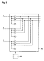
- FIG. 5 shows a switching device for the further compensation circuit from Fig. 4.
- the switching device S2 contains, for example, n inputs and k times n outputs; n is the number of transmission lines, k is the number of adaptive filter per compensation circuit. For example, n is 32 and k is 4. In the switching device there are 128 switches for each of the n inputs intended. The number of switches results from the number of Outputs of the switching device S2, which is 32 times 4 equals 128.
- everyone Switch is connected to each output on one side and on the other other side with an entrance. This gives the opportunity to be able to switch every input to every output. Be controlled the switches by processor P1.
- the fourth switch of the first group is closed in order to connect the first input to the fourth output and to feed the signal of the first transmission line to the fourth adaptive filter of the first compensation circuit and to determine whether the signal of the first signal line has a negative influence on the reception signals of the first reception line.
- a transmission line is assigned a group of switches, e.g. the first transmission line, the first group of switches, the second transmission line, the second group of switches, etc.
- the eighth switch of the second group can be closed to connect the second input with the eighth Connect output and feed the signal of the second transmission line to the fourth adaptive filter of the second compensation circuit and determine whether the signal of the second signal line has a negative influence on the reception signals of the second reception line.
- the twelfth switch of the third group can be closed in order to connect the third input to the twelfth output and to feed the signal of the third transmission line to the fourth adaptive filter of the third compensation circuit and to determine whether the signal of the third signal line has a negative influence on the Received signals of the third receive line, etc.
- the eighth switch of the first group is closed in order to connect the first input to the eighth output and to feed the signal of the first transmission line to the fourth adaptive filter of the second compensation circuit and to determine whether the signal of the first signal line is negative Has influence on the reception signals of the second reception line, etc. It is successively determined which transmission signals have which negative influences on which reception signals.
- those transmission signals are selected and specified as compensation signals that each have the greatest interference.
- the selected, specific signals are then fed to the compensation circuits by closing the corresponding switches. If, for example, the transmission signals of the first, fourth, tenth and fourteenth transmission lines have been determined as the largest interferers for the first reception line, the first switch of the first group, the second switch of the fourth group, the third switch of the tenth group and the fourth switch of the fourteenth group closed.
- the implementation of the switching device S2 is exemplary and can be replaced by any other implementation that fulfills the function, to be able to switch every input to every compensation circuit. Instead of separate lines, an implementation by means of one or more buses can be used.
- Both exemplary embodiments can be combined with one another.
- four adaptive filters can be used in a compensation circuit and two comparators are used. It is also possible in one Compensation circuit four adaptive filters and a comparator use, the comparator has four switches with the four adaptive Filtering is connected for the purpose of activation if necessary.
- Adders can be used instead of two, etc.
- the numbers are exemplary.
- a switching device can be used for example, only 16, 24 or even 64 receive lines be compensated.
- 32 receive lines to be compensated can be used in each compensation circuit instead of four e.g. also 2, 6 or 8 adaptive filters can be provided.
- Receive lines can be used in any compensation circuit e.g. 2, 4 or 6 adaptive filters can be provided.
- Both switching devices S1 and S2 each have a number of Inputs and a number of outputs.
- the number of inputs can n + m, where n is the number of transmission lines in a group of Corresponds to transmission lines that are transmitted in a bundle of lines become.
- n can assume the values 16, 24, 32, 64.
- m corresponds, for example, to the number of receive lines that one Group of receive lines belonging in a bundle of Lines are transmitted. In a bundle of lines are mostly Dummy lines are also available, some of which serve as reserve lines and not be used for data traffic and therefore as Dummy lines act.
- m can also be the number of reception and Blind lines correspond.
- the number of inputs one Switching device can be n or m depending on the application be limited.
Abstract
Description
Die Erfindung betrifft eine Telekommunikations-Vorrichtung zur Kompensation von Nebensprechen.The invention relates to a telecommunications device for Crosstalk compensation.
In EP 0 480 323 B1 ist eine Leitungseinrichtung zur Kompensation von Nebensprechen offenbart. Referenzsignale, die aus Sende- und/oder Empfangsleitungen entnommen werden, werden über adaptive Filter Empfangsleitungen zugeführt. Durch die negative Addition dieser Referenzsignale zu den Empfangsignalen werden Störungen, die in den Empfangssignalen enthalten sind, kompensiert. Es ist vorgesehen, für jede zu kompensierende Empfangsleitung eine Anzahl von adaptiven Filtern vorzusehen, die mindestens der Anzahl der Sendeleitungen entspricht. Für eine Leitungseinrichtung von beispielsweise 32 Sende- und 32 Empfangsleitungen sind somit mindestens 32 adaptive Filter für jede zu kompensierende Empfangsleitung vorgesehen. Bei 32 Empfangsleitungen sind somit mindestens 32 mal 32 gleich 1024 adaptive Filter notwendig. Adaptive Filter sind teure Bauteile, die die Herstellungskosten einer Leitungseinrichtung erheblich erhöhen.EP 0 480 323 B1 describes a line device for the compensation of Crosstalk revealed. Reference signals consisting of transmit and / or Receive lines are taken out via adaptive filters Received lines. By the negative addition of this Reference signals to the received signals are interference that in the Received signals are included, compensated. It is intended for everyone receive line to be compensated a number of adaptive filters to be provided which corresponds at least to the number of transmission lines. For a line device of, for example, 32 transmit and 32 Receive lines are thus at least 32 adaptive filters for each too compensating reception line provided. With 32 receive lines at least 32 times 32 equal to 1024 adaptive filters are necessary. Adaptive filters are expensive components that add up to the manufacturing cost Increase line setup significantly.
Aufgabe der Erfindung ist es, eine Telekommunikations-Vorrichtung zur Kompensation von Nebensprechen zu schaffen, die die Anzahl der benötigten adaptiven Filter minimiert. The object of the invention is to provide a telecommunications device Compensation of crosstalk to create the number of required adaptive filter minimized.
Gelöst wird diese Aufgabe durch eine Telekommunikations-Vorrichtung
gemäß Patentanspruch 1.This task is solved by a telecommunication device
according to
Durch die Verwendung einer Schaltvorrichtung kann die Anzahl der benötigten adaptiven Filter erheblich reduziert und die Geräuschunterdrückung bei 4-Draht Leitungen optimiert werden. Mittels der Schaltvorrichtung werden nur solche Signale von Sende-, Empfangsund/oder Blindleitungen ausgewählt, die einen erheblichen Störeinfluss auf das jeweilige Empfangssignal haben. Für eine Leitungseinrichtung von beispielsweise 32 Sende- und 32 Empfangsleitungen sind beispielsweise nur 4 adaptive Filter für jede zu kompensierende Empfangsleitung vorgesehen. Bei 32 Empfangsleitungen sind somit nur 32 mal 4 gleich 128 adaptive Filter notwendig. Dies entspricht einer Einsparung von 896 adaptiven Filtern. Es werden für jede Empfangsleitung die vier größten Störer ermittelt und diese als Kompensationssignale der Empfangsleitung zugeführt. Durch die negative Addition dieser ausgewählten Kompensationssignale zu den Empfangsignalen werden Störungen, die in den Empfangssignalen enthalten sind, erheblich kompensiert. Der Vorteil der geringeren Anzahl von adaptiven Filtern wird erkauft mit dem geringeren Kompensationsgrad, da nun nicht mehr alle Sende-, Empfangsund/oder Blindleitungsstörsignale kompensiert werden können. Doch wird durch die Limitierung auf eine bestimmte Anzahl von adaptiven Filtern, z.B. vier für jede Empfangsleitung, eine ausreichende Kompensation im Bereich von 70 bis 90 % erzielt, da beispielsweise die vier größten Stören prozentual sehr gewichtig sind und die Hinzunahme weiterer Kompensationssignale die Kompensation nur unwesentlich verbessern würde. Mittels der Schaltvorrichtung und den Kompensationsschaltungen wird die Möglichkeit geschaffen in einer Trainingsphase für jede Empfangsleitung individuell zu ermitteln, welche der anderen Leitungen sie negativ beeinflusst. Nach Abschluss der Trainingsphase sind für jede Empfangsleitung die vier größten Störer ermittelt und werden als Kompensationssignale der jeweiligen Empfangsleitung zugeführt. Die Trainingsphase kann in regelmäßigen zeitlichen Abständen wiederholt werden, um die Kompensation zu optimieren. Dies kann auch während des Betriebs erfolgen.By using a switching device, the number of required adaptive filter significantly reduced and noise suppression with 4-wire lines can be optimized. By means of the Switching device are only such signals from transmit, receive and / or Blind lines selected that have a significant interference have the respective received signal. For a line facility from for example, 32 transmit and 32 receive lines are, for example only 4 adaptive filters for each receive line to be compensated intended. With 32 receive lines, only 32 times 4 are 128 adaptive filter necessary. This corresponds to a saving of 896 adaptive filters. The four largest are for each receive line Disturbers determined and these as compensation signals of the receive line fed. By the negative addition of these selected Compensation signals to the received signals are interference that in the received signals are contained, significantly compensated. The advantage the smaller number of adaptive filters is bought with the lower degree of compensation, since not all transmit, receive and / or Blind line interference signals can be compensated. But it will by limiting it to a certain number of adaptive filters, e.g. four for each receive line, adequate compensation in the range achieved from 70 to 90% because, for example, the four largest disruptors percentages are very important and the addition of more Compensation signals only slightly improve the compensation would. By means of the switching device and the compensation circuits the opportunity is created in a training phase for everyone Receive line individually to determine which of the other lines you negatively influenced. After completing the training phase are for everyone The four largest interferers and are identified as Compensation signals supplied to the respective reception line. The Training phase can be repeated at regular time intervals to optimize the compensation. This can also happen during the Operational.
Vorteilhafte Ausgestaltungen der Erfindung sind den abhängigen Ansprüchen sowie der nachfolgenden Beschreibung zu entnehmen.Advantageous embodiments of the invention are dependent Claims and the following description.
Im folgenden werden zwei Ausführungsbeispiele der Erfindung unter Zuhilfenahme von fünf Figuren erläutert. Es zeigen:
- Fig. 1
- eine schematische Darstellung eines Ausschnitts eines DSL Access Multiplexers beinhaltend eine erfindungsgemäße Telekommunikations-Vorrichtung zur Kompensation von Nebensprechen,
- Fig. 2
- eine schematische Darstellung einer Kompensationsschaltung der erfindungsgemäßen Telekommunikations-Vorrichtung aus Fig. 1,
- Fig. 3
- eine schematische Darstellung eines Echo-Cancellers der Kompensationsschaltung aus Fig. 2,
- Fig. 4
- eine schematische Darstellung einer weiteren Kompensationsschaltung der erfindungsgemäßen Telekommunikations-Vorrichtung aus Fig. 1 und
- Fig. 5
- eine schematische Darstellung einer Schaltvorrichtung für die weitere Kompensationsschaltung aus Fig. 4.
- Fig. 1
- 1 shows a schematic representation of a section of a DSL access multiplexer including a telecommunication device according to the invention for compensating crosstalk,
- Fig. 2
- 2 shows a schematic illustration of a compensation circuit of the telecommunication device according to the invention from FIG. 1,
- Fig. 3
- 2 shows a schematic illustration of an echo canceller of the compensation circuit from FIG. 2,
- Fig. 4
- is a schematic representation of a further compensation circuit of the telecommunication device according to the invention from Fig. 1 and
- Fig. 5
- 3 shows a schematic representation of a switching device for the further compensation circuit from FIG. 4.
Das erste Ausführungsbeispiel wird nun unter Zuhilfenahme der Figuren 1 bis 3 erläutert.The first exemplary embodiment will now be described with the aid of FIGS. 1 to 3 explained.
Fig. 1 zeigt einen Ausschnitts eines DSL Access Multiplexers beinhaltend eine erfindungsgemäße Telekommunikations-Vorrichtung zur Kompensation von Nebensprechen. 1 shows a section of a DSL access multiplexer including an inventive telecommunications device for Crosstalk compensation.
DSL Access Multiplexer werden üblicherweise als DSLAM oder ASAM = Advanced Services Access Manager bezeichnet; DSL = Digital Subscriber Line. Sie werden eingesetzt in Zugangsnetzen der Telekommunikation. Teilnehmerseitig ist ein DSLAM mit einer Vielzahl von Teilnehmern verbunden; dies können private Teilnehmer und/oder Geschäftskunden sein. Netzseitig ist ein DSLAM z.B. mit Edge Equipment, einem Edge Router, einem Remote DSLAM, dem ATM, dem SDH, dem SONET, dem Ethernet oder dem Internet verbunden; ATM = Asynchroner Transfer Modus, SDH = Synchrone Digitale Hierarchie, SONET = Synchronous Optical Network. Ein DSLAM ist üblicherweise in einem Central Office angeordnet. Teilnehmerseitig werden über 2-Draht Leitungen verschiedene Dienste zur Verfügung gestellt. Dies können sein: ADSL, HDSL, G.SHDSL, VoDSL, POTS, ISDN, Voice, Data, Video, etc., VoDSL = Voice over DSL, POTS = Public Switched Telephone Network, ISDN = Integrated Digital Services Network. Die 2-Draht Leitungen mehrerer Teilnehmer werden zumeist in einem Bündel verlegt. Durch die örtliche Nähe zueinander können Signale von der einen Leitung auf eine andere übersprechen. Dies führt zu Störungen in der einen Leitung. Allgemein wird dies als Nebensprechen bezeichnet. Darunter werden auch Impulsstörungen, Echos, Übersprechen, Nahnebensprechen und Fernnebensprechen subsumiert. Bevor die Teilnehmersignale im DSLAM gemultiplext und netzseitig weitergeleitet werden ist es vorteilhaft das Nebensprechen weitestgehend zu kompensieren.DSL access multiplexers are usually called DSLAM or ASAM = Advanced Services Access Manager; DSL = digital subscriber Line. They are used in telecommunications access networks. The subscriber side is a DSLAM with a large number of subscribers connected; this can be private participants and / or business customers his. On the network side, a DSLAM is e.g. with edge equipment, an edge router, a remote DSLAM, the ATM, the SDH, the SONET, the Ethernet or connected to the internet; ATM = asynchronous transfer mode, SDH = Synchronous digital hierarchy, SONET = Synchronous Optical Network. On DSLAM is usually located in a central office. Different services are available on the subscriber side via 2-wire lines Provided. These can be: ADSL, HDSL, G.SHDSL, VoDSL, POTS, ISDN, Voice, Data, Video, etc., VoDSL = Voice over DSL, POTS = Public Switched Telephone Network, ISDN = Integrated Digital Services Network. The 2-wire lines of several participants are mostly in a bundle. Due to the local proximity to each other, signals can crosstalk from one line to another. this leads to Faults in one line. Generally this is called crosstalk designated. This includes impulse interference, echoes, crosstalk, Near-end crosstalk and far-end crosstalk subsumed. Before that Subscriber signals in the DSLAM are multiplexed and forwarded on the network side it is advantageous to crosstalk as much as possible compensate.
Im DSLAM in Fig. 1 sind nur die für das Verständnis der Kompensation des Nebensprechens relevanten Bauteile angegeben. Die weiteren Bauteile eines DSLAM sind dem Fachmann geläufig.In the DSLAM in Fig. 1 are only those for understanding the compensation of the Relevant components specified. The other components a DSLAM are familiar to the person skilled in the art.
Der DSLAM beinhaltet n DSL-Schaltkreise DSL1, DSL2, DSLn, n Weichen W1, W2, Wn, n Kompensationsschaltungen K1, K2, Kn sowie eine Schaltvorrichtung S1; n ist eine natürliche Zahl, z.B. 32. The DSLAM contains n DSL circuits DSL1, DSL2, DSLn, n switches W1, W2, Wn, n compensation circuits K1, K2, Kn and one Switching device S1; n is a natural number, e.g. 32nd
Ein DSL-Schaltkreis DSL1, DSL2, DSLn beinhaltet Bauteile wie einen DSL-Modulator, einen DSL-Demodulator, Filter, Entzerrer, Entwürfler, Entscheider, Kodierer, Dekodierer, Protokollumsetzer, etc. Er dient dazu einen Schnittstelle für einen bestimmten DSL-Dienst bereitzustellen und ist üblicherweise als integrierte Schaltung ausgeführt. Die DSL-Schaltkreise DSL1, DSL2, DSLn sind beispielsweise auf einer oder mehreren Line Cards oder einem oder mehreren Boards platziert.A DSL circuit DSL1, DSL2, DSLn contains components such as a DSL modulator, a DSL demodulator, filter, equalizer, descrambler, Decision makers, encoders, decoders, protocol converters, etc. It serves this purpose to provide an interface for a specific DSL service and is usually implemented as an integrated circuit. The DSL circuits DSL1, DSL2, DSLn are for example on one or more line cards or one or more boards.
Ein Weiche W1, W2, Wn, auch als Gabelschaltung bezeichnet, dient der Separierung von Sende- und Empfangsleitung. In der Weiche W1, W2, Wn findet eine 2-Draht 4-Draht Umsetzung statt. Von DLSAM zum Teilnehmer werden Signale bidirektional über eine 2-Draht Leitung übertragen. Im DSLAM wird die 2-Draht Leitung in zwei unidirektionale 2-Draht Leitungen aufgeteilt, eine 2-Draht Leitung dient als Sendeleitung und zur Übertragung von Signalen vom DSLAM zu den Teilnehmern, die andere 2-Draht Leitung dient als Empfangsleitung und zum Empfang von Teilnehmersignalen.A switch W1, W2, Wn, also referred to as a hybrid, serves the Separation of send and receive lines. In the turnout W1, W2, Wn there is a 2-wire 4-wire implementation. From DLSAM to the participant signals are transmitted bidirectionally via a 2-wire line. in the DSLAM will convert the 2-wire line into two unidirectional 2-wire lines divided, a 2-wire line serves as a transmission line and for transmission of signals from the DSLAM to the subscribers, the other 2-wire line serves as a reception line and for receiving subscriber signals.
DSL-Schaltkreise DSL1, DSL2, DSLn und Weichen W1, W2, Wn sind jeweils über eine 4-Draht Leitung (eine Sendeleitung, eine Empfangsleitung) miteinander verbunden. In jede Empfangsleitung ist eine Kompensationsschaltung K1, K2, Kn eingefügt.DSL circuits are DSL1, DSL2, DSLn and turnouts W1, W2, Wn, respectively via a 4-wire line (one transmission line, one reception line) connected with each other. There is one in each receive line Compensation circuit K1, K2, Kn inserted.
Jede Kompensationsschaltung K1, K2, Kn dient dazu, Nebensprechen in einer Empfangsleitung weitestgehend zu kompensieren. Jede Kompensationsschaltung K1, K2, Kn ist mit der Schaltvorrichtung S1 verbunden.Each compensation circuit K1, K2, Kn serves to crosstalk in to largely compensate for a reception line. each Compensation circuit K1, K2, Kn is with the switching device S1 connected.
Die Schaltvorrichtung S1 dient dazu, zusammen mit den Kompensationsschaltungen aus einer Vielzahl von Leitungen für individuelle Empfangsleitungen spezifische Kompensationssignale auszuwählen. Die Schaltvorrichtung hat eine Vielzahl von Eingängen, im Beispiel n + m, und eine Vielzahl von Ausgängen. Die Ausgänge sind mit den Kompensationsschaltungen K1, K2, Kn verbunden, wobei jeweils mehrere Ausgänge mit einer Kompensationsschaltung K1, K2, Kn verbunden sein können, z.B. jeweils vier. Die ersten n Eingänge sind beispielsweise mit den n Sendeleitungen verbunden; n ist eine natürliche Zahl, z.B. 32. Die weiteren m Eingänge sind beispielsweise mit den n Empfangsleitungen und Blindleitungen, d.h. ungenutzten Leitungen verbunden. Die Schaltvorrichtung S1 kann somit aus einem Repertoire von Leitungen schöpfen und aus diesen geeignete Kompensationssignale für die jeweiligen Kompensationsschaltungen K1, K2, Kn auswählen, um eine möglichst effektive Kompensation zu erzielen.The switching device S1 is used together with the Compensation circuits from a variety of lines for individual Select specific compensation signals on the receiving lines. The Switching device has a large number of inputs, in the example n + m, and a variety of exits. The outputs are with the Compensation circuits K1, K2, Kn connected, with several each Outputs can be connected to a compensation circuit K1, K2, Kn can, e.g. four each. The first n inputs are, for example, with the n transmission lines connected; n is a natural number, e.g. 32. The Further m inputs are, for example, with the n receive lines and Blind lines, i.e. unused lines connected. The Switching device S1 can thus be from a repertoire of lines and use these to generate suitable compensation signals for the select respective compensation circuits K1, K2, Kn to a to achieve the most effective compensation possible.
In bisherigen Kompensationsschaltungen erwies es sich stets als Problem nicht zu wissen, welche Leitung welche andere Leitung negativ beeinflusst und folglich Nebensprechen generiert. Dies rührt u.a. von der Verdrillung der Leitungen im Leitungsbündel, das zu den Teilnehmern verlegt ist. Werden nun alle Leitungen pauschal auf jede Leitung zwecks Kompensation rückgekoppelt, so steigt die Anzahl der benötigten adaptiven Filter immens an, was zum einen zu einer Kostenexplosion führt und zum anderen für Zwecke der Kompensation unnötige Rückkopplungen erzeugt, die viel Platz verschwenden. Werden andererseits beispielsweise die Anzahl der Rückkopplungen begrenzt auf alle Sendeleitungen, so werden zum einen eine unter Umständen nicht ausreichende Kompensation erzielt, z.B. nur Nahnebensprechen, und zum anderen für Zwecke der Kompensation unnötige Rückkopplungen erzeugt, die viel Platz verschwenden und die Herstellungskosten erhöhen.In previous compensation circuits, it always proved to be a problem not knowing which line adversely affects which other line and consequently generated crosstalk. Among other things, this affects from the twist of the lines in the line bundle that is routed to the participants. Now all lines are flat on each line for the purpose of compensation fed back, the number of adaptive filters required increases immensely on what leads to a cost explosion on the one hand and on the other for Compensation purposes creates unnecessary feedback that takes up a lot of space waste. On the other hand, for example, the number of Feedback is limited to all transmission lines, so on the one hand underperformance may be achieved, e.g. just Near-end crosstalk, and on the other for purposes of compensation creates unnecessary feedbacks that waste a lot of space and that Increase manufacturing costs.
Mittels der Schaltvorrichtung S1 und den Kompensationsschaltungen K1, K2, Kn aus Fig.1 wird nun die Möglichkeit geschaffen in einer Trainingsphase für jede Empfangsleitung individuell zu ermitteln, welche der anderen Leitungen sie negativ beeinflusst. In der Trainingsphase, die z.B. bei der Initialisierung durchgeführt wird und/oder während des Betriebs in regelmäßigen Abständen, wird ein Datenaufkommen künstlich derart erzeugt, dass alle Sende- und alle Empfangsleitungen mit Signalen belegt sind oder es wird der reelle Datentransfer zugrunde gelegt. Zur Ermittlung welche Leitung Nebensprechen in der ersten Empfangsleitung generiert, schaltet Schaltvorrichtung S1 zunächst die erste Sendeleitung zur ersten Kompensationsschaltung K1 durch. Die erste Kompensationsschaltung K1 ermittelt, ob durch die Rückkopplung mit der ersten Sendeleitung eine Verbesserung der Empfangsqualität auf der ersten Empfangsleitung eintritt und teilt ihr Ergebnis der Schaltvorrichtung S1 mit. Danach schaltet die Schaltvorrichtung S1 die zweite Sendeleitung zur ersten Kompensationsschaltung K1 durch. Die erste Kompensationsschaltung K1 ermittelt, ob durch die Rückkopplung mit der zweiten Sendeleitung eine Verbesserung der Empfangsqualität auf der ersten Empfangsleitung eintritt und teilt ihr Ergebnis der Schaltvorrichtung S1 mit. In der Folge werden sukzessive alle Eingänge der Schaltvorrichtung S1 auf die erste Kompensationsschaltung K1 geschaltet und jeweils der Einfluss auf die Empfangsqualität auf der ersten Empfangsleitung ermittelt. Die Schaltvorrichtung S1 speichert alle Ergebnisse und wählt aus den Leitungen am Eingang der Schaltvorrichtung S1 diejenigen aus, die den größten positiven Einfluss auf die Kompensation generiert haben. Somit werden der ersten Kompensationsschaltung K1 nur Signale von denjenigen Leitungen zugeführt, mittels derer wirklich das Nebensprechen reduziert werden kann.By means of the switching device S1 and the compensation circuits K1, K2, Kn from Fig.1 is now created in a way Training phase to determine individually for each reception line of the other lines negatively affects them. In the training phase, the e.g. is carried out during initialization and / or during operation at regular intervals, data traffic becomes artificial generates that all transmit and receive lines are occupied with signals are or it is based on the real data transfer. For investigation which line generates crosstalk in the first receive line, Switching device S1 first switches the first transmission line to the first Compensation circuit K1 through. The first compensation circuit K1 determines whether a feedback through the first transmission line Improvement in reception quality occurs on the first reception line and communicates its result to the switching device S1. Then the Switching device S1 the second transmission line to the first Compensation circuit K1 through. The first compensation circuit K1 determines whether a feedback through the second transmission line Improvement in reception quality occurs on the first reception line and communicates its result to the switching device S1. As a result successively all inputs of the switching device S1 to the first Compensation circuit K1 switched and the influence on each Reception quality determined on the first reception line. The Switching device S1 stores all results and selects from the lines at the input of the switching device S1 from the largest have generated a positive influence on the compensation. Thus the first compensation circuit K1 only signals from those lines fed, by means of which the crosstalk can really be reduced.
Auf gleiche Art und Weise wird auch für die übrigen n-1 Empfangsleitungen eine Auswahl von Leitungen getroffen, die für Kompensationszwecke verwendet werden.In the same way, the other n-1 receive lines made a selection of lines for compensation purposes be used.
Die Anzahl der adaptiven Filter je Kompensationsschaltung K1, K2, Kn ist begrenzt. Für jede Kompensationsschaltung K1, K2, Kn ist eine geeignete Anzahl zu wählen. Bei 32 Sendeleitungen und 32 Empfangsleitungen werden z.B. 4 adaptive Filter zum Zwecke der Kompensation des Nebensprechens auf einer Empfangsleitung mittels Signalen von vier ermittelten Störleitungen verwendet. Die Anzahl der adaptiven Filter wird zum einen so gewählt, dass eine ausreichende Kompensation erzielt werden kann und zum anderen die Herstellungskosten für eine Kompensationsschaltung K1, K2, Kn minimiert werden.The number of adaptive filters per compensation circuit K1, K2, Kn is limited. A suitable one is for each compensation circuit K1, K2, Kn Number to choose. With 32 transmission lines and 32 reception lines e.g. 4 adaptive filters for the purpose of compensating the Crosstalk on a receive line using signals from four interference lines determined. The number of adaptive filters will on the one hand, chosen so that adequate compensation is achieved and on the other hand the manufacturing costs for a Compensation circuit K1, K2, Kn can be minimized.
Es hat sich gezeigt, dass bei 32 Sendeleitungen und 32 Empfangsleitungen eine ausreichende Kompensation im Bereich von 70-90% erzielt werden kann, wenn die vier stärksten Störer kompensiert werden. Dies bedeutet, dass wenn die vier stärksten Störer identifiziert sind, es ausreichend ist, die entsprechenden Leitungen rückzukoppeln.It has been shown that with 32 transmission lines and 32 reception lines Adequate compensation in the range of 70-90% can be achieved can, if the four strongest interferers are compensated. This means, that when the four strongest disruptors are identified, it is sufficient that appropriate lines to feed back.
In der Trainingsphase wurden für die erste Empfangsleitung beispielsweise die dritte Sendeleitung, die sechszehnte Sendeleitung, die vierte Empfangsleitung und die neuzehnte Empfangsleitung als die stärksten Störer ermittelt. Die Schaltvorrichtung S1 schaltet dann diese Leitungen zur ersten Kompensationsschaltung K1 permanent durch, um während des Betriebs eine optimierte Kompensation des Nebensprechens zu erzielen.In the training phase, for example, for the first reception line the third transmission line, the sixteenth transmission line, the fourth Receiving line and the nineteenth receiving line as the strongest Detector identified. The switching device S1 then switches these lines on first compensation circuit K1 by in order to during the Operation to achieve optimized cross-talk compensation.
In einer bevorzugten Ausführungsform kann während des Betriebs der Kompensationsgrad der ausgewählten Kompensationssignale stetig oder in regelmäßigen Abständen überwacht werden. Kompensationssignale, die im realen Betrieb keinen oder nur untergeordneten Einfluss auf die Kompensation haben können durch Kompensationssignale anderer Leitungen ausgetauscht werden. Die Überwachung und die Umschaltung auf andere Leitungen wird beispielsweise durch einen in der Schaltvorrichtung S1 integrierten Prozessor und einen Speicher durchgeführt. Der Prozessor ist. z.B. als Mikroprozessor oder als Digitaler Signalprozessor ausgeführt. Im Speicher sind beispielsweise für jede Empfangsleitung alle Eingangsleitungen geordnet nach ihrem Kompensationsgrad für die jeweilige Empfangsleitung gespeichert. Ermittelt der Prozessor im realen Betrieb, dass z.B. die zweite der vier ausgewählten Leitungen keinen oder nur einen untergeordneten Einfluss auf die Kompensation hat, so wird diese Leitung nicht mehr zur entsprechenden Kompensationsschaltung K1, K2, Kn durchgeschaltet. Die im Speicher als fünftbeste Leitung abgespeicherte Leitung wird nun zusätzlich zu der ersten, dritten und vierten ausgewählten Leitung durchgeschaltet. Ermittelt der Prozessor im realen Betrieb, dass die fünftbeste Leitung keinen oder nur einen untergeordneten Einfluss auf die Kompensation hat, so wird diese Leitung nicht mehr zur entsprechenden Kompensationsschaltung K1, K2, Kn durchgeschaltet. Die im Speicher als sechstbeste Leitung abgespeicherte Leitung wird nun zusätzlich durchgeschaltet. Der Prozessor ist somit in der Lage, die Rangfolge der ausgewählten Leitungen während des Betriebs zu ändern und die Kompensation des Nebensprechens zu optimieren. Durch Speicherung der aktuelle Konfiguration und Wiederverwendung bei der nächsten Verbindung ist der Prozessor in der Lage, für jede Empfangsleitung individuell eine optimierte Kompensation des Nebensprechens bereitzustellen und darauf aufbauend gegebenenfalls eine adaptive Optimierung während des Betriebs durchzuführen.In a preferred embodiment, the Degree of compensation of the selected compensation signals steady or in be monitored at regular intervals. Compensation signals in the real operation no or only minor influence on the Can have compensation through compensation signals of others Lines are exchanged. Monitoring and switching to other lines, for example, by one in the Switching device S1 integrated processor and a memory carried out. The processor is. e.g. as a microprocessor or as a digital Signal processor executed. For example, there are in memory for everyone Receive line all input lines sorted according to their Degree of compensation stored for the respective receive line. determined the processor in real operation, e.g. the second of the four selected Lines have no or only a minor influence on the Compensation, this line will no longer become the corresponding one Compensation circuit K1, K2, Kn switched through. Those in store as fifth best line stored line is now in addition to the first, third and fourth selected line switched through. Finds the Processor in real operation that the fifth best line has no or only has a subordinate influence on the compensation, it becomes Line no longer to the corresponding compensation circuit K1, K2, Kn connected through. The sixth best line stored in memory The line is now also switched through. The processor is therefore in the Able to rank the selected lines during operation change and optimize the crosstalk compensation. By Storage of the current configuration and reuse at the next connection, the processor is able for each Receive line individually an optimized compensation of the Provide crosstalk and, if necessary, build on it perform adaptive optimization during operation.
Fig. 2 zeigt eine Kompensationsschaltung der erfindungsgemäßen Telekommunikations-Vorrichtung aus Fig. 1. Im folgenden wird ein detaillierter Aufbau der ersten Kompensationsschaltung K1 aus Fig. 1 beschrieben. Die übrigen n-1 Kompensationsschaltungen K2, Kn entsprechen in ihrem Aufbau und Funktionsweise der ersten Kompensationsschaltung K1.Fig. 2 shows a compensation circuit of the invention Telecommunications device of Fig. 1. In the following is a detailed structure of the first compensation circuit K1 from FIG. 1 described. The remaining n-1 compensation circuits K2, Kn correspond in structure and mode of operation to the first Compensation circuit K1.
Kompensationsschaltung K1 ist mit der ersten Weiche W1, dem ersten DSL-Schaltkreis DSL1 und der Schaltvorrichtung S1 verbunden. Sie dient der Kompensation von Nebensprechen in der ersten Empfangsleitung.Compensation circuit K1 is with the first switch W1, the first DSL circuit DSL1 and the switching device S1 connected. It serves the Crosstalk compensation in the first receive line.
Kompensationsschaltung K1 weist vier Echo Canceller E1, E2, E3, E4 und zwei Addierer A1, A2 auf.Compensation circuit K1 has four echo cancellers E1, E2, E3, E4 and two adders A1, A2.
Jeder Echo Canceller E1, E2, E3, E4 dient der Bereitstellung eines Kompensationssignals und der Ermittlung des Korrelationsgrads des Kompensationssignals. Die Kompensationssignale der vier Echo Canceller E1, E2, E3, E4 werden im Addierer A2 addiert und mittels des Addierers A1 negativ zu den Empfangssignalen der ersten Empfangsleitung addiert zwecks Kompensation des Nebensprechens. Die Empfangssignale und die negativ addierten Kompensationssignale werden zu den Echo Cancellern E1, E2, E3, E4 rückgekoppelt. Each Echo Canceller E1, E2, E3, E4 is used to provide one Compensation signal and the determination of the degree of correlation Compensation signal. The compensation signals of the four echo cancellers E1, E2, E3, E4 are added in the adder A2 and by means of the adder A1 added negatively to the reception signals of the first reception line to compensate for crosstalk. The received signals and the negatively added compensation signals become the echo cancellers E1, E2, E3, E4 fed back.
Fig. 3 zeigt einen Echo-Canceller der Kompensationsschaltung aus Fig. 2. Im folgenden wird ein detaillierter Aufbau des ersten Echo Cancellers E1 aus Fig. 2 beschrieben. Die übrigen drei Echo Canceller E2, E3, E4 entsprechen in ihrem Aufbau und Funktionsweise dem ersten Echo Canceller E1.FIG. 3 shows an echo canceller of the compensation circuit from FIG. 2. The following is a detailed structure of the first Echo Canceller E1 described from Fig. 2. The remaining three Echo Canceller E2, E3, E4 correspond in structure and mode of operation to the first echo Canceller E1.
Echo Canceller E1 ist mit der Schaltvorrichtung S1, dem Addierer A2 sowie der ersten Empfangsleitung vor und nach dem Addierer A1 verbunden. Echo Canceller E1 dient der Bereitstellung eines Kompensationssignals und der Ermittlung des Korrelationsgrads des Kompensationssignals und weist dazu ein adaptives Filter F1 und einen Vergleicher V1 auf.Echo Canceller E1 is with the switching device S1, the adder A2 as well the first reception line before and after the adder A1. Echo Canceller E1 is used to provide a compensation signal and the determination of the degree of correlation of the compensation signal and points an adaptive filter F1 and a comparator V1.
Das adaptive Filter F1 hat zwei Eingänge und einen Ausgang. Dem einen Eingang wird von der Schaltvorrichtung S1 das Kompensationssignal einer ausgewählten Kompensationsleitung zugeführt. Dem anderen Eingang ist das rückgekoppelte Empfangsignal der ersten Empfangsleitung zugeführt. Die Filterparameter bzw. Filterkoeffizienten werden z.B. durch einen geeigneten Adaptionsalgorithmus ermittelt. Jedes adaptive Filter weist z.B. ca. 50 Koeffizientenblöcke bzw. Gatter auf, so dass je eingespartem Filter eine erhebliche Kostenreduktion erfolgt. Wenn das Kompensationssignal im rückgekoppelten Empfangssignal vorhanden ist korreliert es im adaptiven Filter und steht am Ausgang des adaptiven Filter zur Kompensation zur Verfügung.The adaptive filter F1 has two inputs and one output. The one The compensation signal is input from the switching device S1 selected compensation line fed. The other entrance is fed back the received signal of the first receive line. The filter parameters or filter coefficients are e.g. through a suitable adaptation algorithm determined. Each adaptive filter has e.g. approx. 50 coefficient blocks or gates, so that each filter saved there is a significant cost reduction. If the compensation signal in feedback received signal is present it correlates in the adaptive Filter and is available at the output of the adaptive filter for compensation Available.
Der Vergleicher V1 hat zwei Eingänge und einen Ausgang. Dem einen Eingang ist das Ausgangssignal des adaptiven Filters F1 zugeführt. Dem anderen Eingang ist das Empfangssignal der ersten Empfangsleitung zugeführt. Der Vergleicher V1 ermittelt den Korrelationsgrad eines dem adaptiven Filter F1 zugeführten Kompensationssignals. Der Vergleicher V1 ist im einfachsten fall als Komparator aufgebaut, um zu entscheiden, ob das Kompensationssignal korreliert oder nicht korreliert, also für Kompensationszwecke verwendet werden kann oder nicht. Durch Verwendung eines Bitvergleichers kann der Korrelationsgrad quantifiziert werden, also ermittelt werden, wie gut ein Kompensationssignal korreliert. The comparator V1 has two inputs and one output. The one The output signal of the adaptive filter F1 is fed to the input. the the other input is the receive signal of the first receive line fed. The comparator V1 determines the degree of correlation of the adaptive filter F1 supplied compensation signal. The comparator V1 in the simplest case it is constructed as a comparator to decide whether the compensation signal is correlated or not correlated, ie for Compensation purposes may or may not be used. By The degree of correlation can be quantified using a bit comparator are determined, that is, how well a compensation signal correlates.
Das Ausgangssignal des Vergleichers V1 wird zur Schaltvorrichtung S1 übertragen, die daraufhin die Auswahl eines bestimmten Kompensationssignals als spezifisches, für die Kompensation zu verwendendes oder nicht zu verwendendes durchführt.The output signal of the comparator V1 becomes the switching device S1 transferred, which is then the selection of a particular one Compensation signal as specific, for compensation too uses or does not use.
Beim ersten Ausführungsbeispiel ist die Telekommunikations-Vorrichtung zur Kompensation von Nebensprechen in einem DSLAM angeordnet. Anstelle in einem DSLAM kann die Telekommunikations-Vorrichtung auch an einer anderen Stelle im Telekommunikationsnetz angeordnet werden. Erforderlich ist nur die Bereitstellung einer 4-Draht Leitung. Dies kann durch zwei Weichen bereitgestellt werden oder an einer Stelle im Telekommunikationsnetz erfolgen, an der eine 4-Draht Leitung vorgesehen ist.In the first embodiment, the telecommunication device arranged to compensate for crosstalk in a DSLAM. Instead of a DSLAM, the telecommunication device can also to be located at another location in the telecommunications network. All that is required is a 4-wire cable. This can be done by two switches are provided or at one point in the Telecommunications network take place on which a 4-wire line is provided is.
In vorteilhafter Weise können zwischen Weiche W1 und Addierer A1 noch Bauelemente wie ein A/D-Umsetzer und ein Bandpassfilter eingefügt werden.Advantageously, there can still be between the switch W1 and the adder A1 Components such as an A / D converter and a bandpass filter inserted become.
Die Schaltvorrichtung S1 kann in vorteilhafter Weise eine Schaltmatrix, eine Auswerteeinheit und eine Recheneinheit beinhalten. Alternativ beinhaltet die Schaltvorrichtung S1 eine Vielzahl von Schaltern, die von einem außerhalb der Schaltvorrichtung S1 angeordneten Prozessor angesteuert werden. Der Prozessor hat Zugriff auf einen Speicher, auf dem zumindest die Information über die ausgewählten, spezifischen Kompensationsleitungen gespeichert sind.The switching device S1 can advantageously a switching matrix, a Include evaluation unit and a computing unit. Alternatively, the Switching device S1 a variety of switches from one outside of the switching device S1 arranged processor can be controlled. The Processor has access to a memory on which at least the Information about the selected, specific compensation lines are saved.
In einem DSLAM können ein Prozessor und mehrere Schaltvorrichtungen vorhanden sein. Mittels des einen Prozessors werden dann alle Schaltvorrichtungen gesteuert. Jede Schaltvorrichtung stellt Kompensationssignale für eine Gruppe von Empfangsleitungen bereit. Einer Gruppe gehören beispielsweise 32 Empfangsleitungen an. Für die 32 Empfangsleitungen werden 32 Kompensationsschaltungen benötigt. Jede Kompensationsschaltung beinhaltet vier adaptive Filter zur Bereitstellung von vier Kompensationssignalen. Für die gesamte Gruppe werden lediglich vier mal 32 gleich 128 adaptive Filter benötigt. Eine Schaltvorrichtung stellt somit 128 Kompensationssignale zur Verfügung.In a DSLAM, a processor and several switching devices to be available. By means of the one processor, all are then Switching devices controlled. Each switching device provides Compensation signals for a group of receive lines ready. one For example, 32 receive lines belong to the group. For the 32nd 32 compensation circuits are required. each Compensation circuit includes four adaptive filters for provision of four compensation signals. For the entire group, only four times 32 equal 128 adaptive filters needed. A switching device provides 128 compensation signals are available.
Das zweite Ausführungsbeispiel wird nun unter Zuhilfenahme der Figuren 4 und 5 erläutert.The second exemplary embodiment will now be described with the aid of FIGS. 4 and 5 explained.
Fig. 4 zeigt eine Kompensationsschaltung der erfindungsgemäßen Telekommunikations-Vorrichtung aus Fig. 1. Im folgenden wird ein detaillierter Aufbau der ersten Kompensationsschaltung K1 aus Fig. 1 beschrieben. Die übrigen n-1 Kompensationsschaltungen K2, Kn entsprechen in ihrem Aufbau und Funktionsweise der ersten Kompensationsschaltung K1. Die Schaltvorrichtung S1 ist als Schaltvorrichtung S2 plus Prozessor P1 ausgeführt.Fig. 4 shows a compensation circuit of the invention Telecommunications device of Fig. 1. In the following is a detailed structure of the first compensation circuit K1 from FIG. 1 described. The remaining n-1 compensation circuits K2, Kn correspond in structure and mode of operation to the first Compensation circuit K1. The switching device S1 is as Switching device S2 plus processor P1 executed.
Kompensationsschaltung K1 ist mit der ersten Weiche W1, dem ersten DSL-Schaltkreis DSL1 und der Schaltvorrichtung S2 verbunden. Sie dient der Kompensation von Nebensprechen in der ersten Empfangsleitung.Compensation circuit K1 is with the first switch W1, the first DSL circuit DSL1 and the switching device S2 connected. It serves the Crosstalk compensation in the first receive line.
Kompensationsschaltung K1 weist vier adaptive Filter F1, F2, F3, F4, einen Vergleicher V4 und vier Addierer A3, A4, A5, A6 auf.Compensation circuit K1 has four adaptive filters F1, F2, F3, F4, one Comparator V4 and four adders A3, A4, A5, A6.
Jedes adaptive Filter F1, F2, F3, F4 dient der Bereitstellung eines Kompensationssignals. Vergleicher V4 dient der Ermittlung des Korrelationsgrads des Kompensationssignals. Die Kompensationssignale der vier adaptiven Filter F1, F2, F3, F4 werden im zugehörigen Addierer A3, A4, A5, A6 negativ zu den Empfangsignalen der ersten Empfangsleitung addiert zwecks Kompensation des Nebensprechens. Die Empfangssignale und die negativ addierten Kompensationssignale werden zu den adaptiven Filtern F1, F2, F3, F4 rückgekoppelt.Each adaptive filter F1, F2, F3, F4 serves to provide one Compensation signal. Comparator V4 is used to determine the Degree of correlation of the compensation signal. The compensation signals of the four adaptive filters F1, F2, F3, F4 are in the associated adder A3, A4, A5, A6 negative to the reception signals of the first Receive line adds to compensate for crosstalk. The Receive signals and the negatively added compensation signals are fed back to the adaptive filters F1, F2, F3, F4.
Das adaptive Filter F1 hat zwei Eingänge und einen Ausgang. Dem einen Eingang wird von der Schaltvorrichtung S2 das Kompensationssignal einer ausgewählten Kompensationsleitung zugeführt. Dem anderen Eingang ist das rückgekoppelte Empfangsignal der ersten Empfangsleitung zugeführt. Die Filterparameter werden z.B. durch einen geeigneten Adaptionsalgorithmus ermittelt. Wenn das Kompensationssignal im rückgekoppelten Empfangssignal vorhanden ist korreliert es im adaptiven Filter und steht am Ausgang des adaptiven Filter zur Kompensation zur Verfügung.The adaptive filter F1 has two inputs and one output. The one The compensation signal is an input from the switching device S2 selected compensation line fed. The other entrance is fed back the received signal of the first receive line. The filter parameters are e.g. by a suitable one Adaptation algorithm determined. If the compensation signal in feedback received signal is present it correlates in the adaptive Filter and is available at the output of the adaptive filter for compensation Available.
Der Vergleicher V4 hat zwei Eingänge und einen Ausgang. Dem einen Eingang ist das Ausgangssignal des adaptiven Filters F4 zugeführt. Dem anderen Eingang ist das Empfangssignal der ersten Empfangsleitung zugeführt. Der Vergleicher V4 ermittelt den Korrelationsgrad eines dem adaptiven Filter F4 zugeführten Kompensationssignals. Der Vergleicher V4 ist im einfachsten fall als Komparator aufgebaut, um zu entscheiden, ob das Kompensationssignal korreliert oder nicht korreliert, also für Kompensationszwecke verwendet werden kann oder nicht. Durch Verwendung eines Bitvergleichers kann der Korrelationsgrad quantifiziert werden, also ermittelt werden, wie gut ein Kompensationssignal korreliert. Das Ausgangssignal des Vergleichers V4 wird zum Prozessor P1 übertragen, der daraufhin über die Schaltvorrichtung S2 die Auswahl eines bestimmten Kompensationssignals als spezifisches, für die Kompensation zu verwendendes oder nicht zu verwendendes durchführt.The comparator V4 has two inputs and one output. The one Input is the output signal of the adaptive filter F4. the the other input is the receive signal of the first receive line fed. The comparator V4 determines the degree of correlation of the adaptive filter F4 supplied compensation signal. The comparator V4 in the simplest case it is constructed as a comparator to decide whether the compensation signal is correlated or not correlated, ie for Compensation purposes may or may not be used. By The degree of correlation can be quantified using a bit comparator are determined, that is, how well a compensation signal correlates. The output signal of the comparator V4 becomes the processor P1 transmitted, which is then selected via the switching device S2 certain compensation signal as specific, for the compensation too uses or does not use.
Beim zweiten Ausführungsbeispiel wird je Kompensationsschaltung nur ein Vergleicher benötigt. Dies reduziert die Herstellungskosten. Während der Trainingsphase wird jeder Kompensationsschaltung sukzessive ein Kompensationssignal zur Ermittlung des Korrelationsgrads zugeführt. Dazu ist nur ein Vergleicher notwendig. Damit können gegenüber dem ersten Ausführungsbeispiel drei Vergleicher je Kompensationsschaltung eingespart werden, allerdings mit dem Nachteil, dass während des Betriebs nicht gleichzeitig alle vier adaptiven Filter überwacht werden können. Dies kann dadurch teilweise behoben werden, dass während des Betriebs die Kompensationssignale zeitlich rollierend über die vier adaptiven Filter verteilt werden, so dass in gewissen Zeitabschnitten sukzessive alle vier ausgewählten Kompensationssignale am adaptiven Filter F4 anliegen und somit eine Überwachung zumindest zeitweise möglich ist. Das erste Ausführungsbeispiel behält allerdings den Vorteil, dass während der Trainingsphase gleichzeitig vier Kompensationssignale zur Ermittlung des Korrelationsgrads einer Kompensationsschaltung zugeführt werden können und somit die Ermittlung der vier stärksten Störer viermal schneller erfolgen kann als beim zweiten Ausführungsbeispiel. Für die Steuerung des Ablaufs während der Trainingsphase und gegebenenfalls während des Betriebs wird die Schaltvorrichtung S1 bzw. der Prozessor P1 entsprechend programmiert.In the second embodiment, only one is used for each compensation circuit Comparator needed. This reduces the manufacturing costs. During the Training phase is successively every compensation circuit Compensation signal for determining the degree of correlation supplied. To only one comparator is necessary. This can be compared to the first Embodiment saved three comparators per compensation circuit , but with the disadvantage that not during operation all four adaptive filters can be monitored simultaneously. This can partially remedied by the fact that the Compensation signals rolling over time via the four adaptive filters be distributed, so that, in certain periods, successively all four selected compensation signals are present at the adaptive filter F4 and monitoring is therefore at least temporarily possible. The first However, the embodiment retains the advantage that during the Training phase simultaneously four compensation signals to determine the Degree of correlation can be supplied to a compensation circuit and thus the four strongest interferers are determined four times faster can than in the second embodiment. For controlling the process during the training phase and possibly during operation the switching device S1 or the processor P1 becomes corresponding programmed.
Beim zweiten Ausführungsbeispiel werden die Ausgangssignale des Addierers A3 auf alle adaptiven Filter F1, F2, F3, F4 zurückgekoppelt. Alternativ können die Ausgangsignale des Addierers A3 auf adaptives Filter F1, die Ausgangsignale des Addierers A4 auf adaptives Filter F2, Ausgangsignale des Addierers A5 auf adaptives Filter F3 und Ausgangsignale des Addierers A6 auf adaptives Filter F4 rückgekoppelt werden.In the second embodiment, the output signals of the Adders A3 fed back to all adaptive filters F1, F2, F3, F4. Alternatively, the output signals of the adder A3 can be applied to adaptive filters F1, the output signals of adder A4 to adaptive filter F2, Output signals from adder A5 to adaptive filter F3 and Output signals of adder A6 fed back to adaptive filter F4 become.
Fig. 5 zeigt eine Schaltvorrichtung für die weitere Kompensationsschaltung aus Fig. 4.5 shows a switching device for the further compensation circuit from Fig. 4.
Die Schaltvorrichtung S2 beinhaltet beispielsweise n Eingänge und k mal n Ausgänge; n ist die Anzahl der Sendeleitungen, k ist die Anzahl der adaptiven Filter je Kompensationsschaltung. n ist beispielsweise 32 und k 4. In der Schaltvorrichtung sind für jede der n Eingänge 128 Schalter vorgesehen. Die Anzahl der Schalter ergibt sich aus der Anzahl der Ausgänge der Schaltvorrichtung S2, die 32 mal 4 gleich 128 beträgt. Jeder Schalter ist auf der einen Seite mit jedem Ausgang verbunden und auf der anderen Seite mit einem Eingang. Dadurch ergibt sich die Möglichkeit, jeden Eingang auf jeden Ausgang schalten zu können. Angesteuert werden die Schalter durch den Prozessor P1.The switching device S2 contains, for example, n inputs and k times n outputs; n is the number of transmission lines, k is the number of adaptive filter per compensation circuit. For example, n is 32 and k is 4. In the switching device there are 128 switches for each of the n inputs intended. The number of switches results from the number of Outputs of the switching device S2, which is 32 times 4 equals 128. Everyone Switch is connected to each output on one side and on the other other side with an entrance. This gives the opportunity to be able to switch every input to every output. Be controlled the switches by processor P1.
Während der Trainingsphase wird z.B. der vierte Schalter der ersten
Gruppe geschlossen, um den ersten Eingang mit dem vierten Ausgang zu
verbinden und das Signal der ersten Sendeleitung dem vierten adaptiven
Filter der ersten Kompensationsschaltung zuzuführen und zu ermitteln, ob
das Signal der ersten Signalleitung einen negativen Einfluss auf die
Empfangssignale der ersten Empfangsleitung hat. Einer Sendeleitung ist
dabei jeweils eine Gruppe von Schaltern zugeordnet, z.B. der ersten
Sendeleitung die erste Gruppe von Schaltern, der zweiten Sendeleitung die
zweite Gruppe von Schaltern, usw. Gleichzeitig kann der achte Schalter der
zweiten Gruppe geschlossen werden, um den zweiten Eingang mit dem
achten Ausgang zu verbinden und das Signal der zweiten Sendeleitung
dem vierten adaptiven Filter der zweiten Kompensationsschaltung
zuzuführen und zu ermitteln, ob das Signal der zweiten Signalleitung einen
negativen Einfluss auf die Empfangssignale der zweiten Empfangsleitung
hat. Gleichzeitig kann der zwölfte Schalter der dritten Gruppe geschlossen
werden, um den dritten Eingang mit dem zwölften Ausgang zu verbinden
und das Signal der dritten Sendeleitung dem vierten adaptiven Filter der
dritten Kompensationsschaltung zuzuführen und zu ermitteln, ob das Signal
der dritten Signalleitung einen negativen Einfluss auf die Empfangssignale
der dritten Empfangsleitung hat, usw.
In einem zweiten Schritt wird z.B. der achte Schalter der ersten Gruppe
geschlossen, um den ersten Eingang mit dem achten Ausgang zu verbinden
und das Signal der ersten Sendeleitung dem vierten adaptiven Filter der
zweiten Kompensationsschaltung zuzuführen und zu ermitteln, ob das
Signal der ersten Signalleitung einen negativen Einfluss auf die
Empfangssignale der zweiten Empfangsleitung hat, usw. Sukzessive wird so
ermittelt, welche Sendesignale welche negativen Einflüsse auf welche
Empfangssignale haben. Nach Abschluss der Ermittlung werden diejenigen
Sendesignale als Kompensationssignale ausgewählt und spezifiziert, die
jeweils die größten Störeinflüsse haben. Die ausgewählten, spezifischen
Signale werden den Kompensationsschaltungen dann durch Schließen der
entsprechenden Schalter zugeführt. Wurden für die erste Empfangsleitung
beispielsweise die Sendesignale der ersten, vierten, zehnten und
vierzehnten Sendeleitungen als größte Störer ermittelt, so werden z.B. der
erste Schalter der ersten Gruppe, der zweite Schalter der vierten Gruppe,
der dritte Schalter der zehnten Gruppe und der vierte Schalter der
vierzehnten Gruppe geschlossen.During the training phase, for example, the fourth switch of the first group is closed in order to connect the first input to the fourth output and to feed the signal of the first transmission line to the fourth adaptive filter of the first compensation circuit and to determine whether the signal of the first signal line has a negative influence on the reception signals of the first reception line. A transmission line is assigned a group of switches, e.g. the first transmission line, the first group of switches, the second transmission line, the second group of switches, etc. At the same time, the eighth switch of the second group can be closed to connect the second input with the eighth Connect output and feed the signal of the second transmission line to the fourth adaptive filter of the second compensation circuit and determine whether the signal of the second signal line has a negative influence on the reception signals of the second reception line. At the same time, the twelfth switch of the third group can be closed in order to connect the third input to the twelfth output and to feed the signal of the third transmission line to the fourth adaptive filter of the third compensation circuit and to determine whether the signal of the third signal line has a negative influence on the Received signals of the third receive line, etc.
In a second step, for example, the eighth switch of the first group is closed in order to connect the first input to the eighth output and to feed the signal of the first transmission line to the fourth adaptive filter of the second compensation circuit and to determine whether the signal of the first signal line is negative Has influence on the reception signals of the second reception line, etc. It is successively determined which transmission signals have which negative influences on which reception signals. After completion of the determination, those transmission signals are selected and specified as compensation signals that each have the greatest interference. The selected, specific signals are then fed to the compensation circuits by closing the corresponding switches. If, for example, the transmission signals of the first, fourth, tenth and fourteenth transmission lines have been determined as the largest interferers for the first reception line, the first switch of the first group, the second switch of the fourth group, the third switch of the tenth group and the fourth switch of the fourteenth group closed.
Die Implementierung der Schaltvorrichtung S2 ist beispielhaft und kann durch jede andere Implementierung ersetzt werden, die die Funktion erfüllt, jeden Eingang auf jede Kompensationsschaltung schalten zu können. Anstelle von separaten Leitungen kann auch eine Implementierung mittels eines oder mehrerer Busse verwendet werden.The implementation of the switching device S2 is exemplary and can be replaced by any other implementation that fulfills the function, to be able to switch every input to every compensation circuit. Instead of separate lines, an implementation by means of one or more buses can be used.
Beide Ausführungsbeispiele können miteinander kombiniert werden. Beispielsweise können in einer Kompensationsschaltung vier adaptive Filter und zwei Vergleicher verwendet werden. Es ist auch möglich in einer Kompensationsschaltung vier adaptive Filter und einen Vergleicher zu verwenden, wobei der Vergleicher über vier Schalter mit den vier adaptiven Filtern verbunden ist zwecks Zuschaltung bei Bedarf. Beim ersten Ausführungsbeispiel können wie beim zweiten Ausführungsbeispiel vier Addierer verwendet werden statt zwei, usw.Both exemplary embodiments can be combined with one another. For example, four adaptive filters can be used in a compensation circuit and two comparators are used. It is also possible in one Compensation circuit four adaptive filters and a comparator use, the comparator has four switches with the four adaptive Filtering is connected for the purpose of activation if necessary. At the first Embodiment can four as in the second embodiment Adders can be used instead of two, etc.
In beiden Ausführungsbeispielen sind die Angaben von Zahlen beispielhaft. Anstelle von 32 Empfangsleitungen können mittels einer Schaltvorrichtung beispielsweise auch nur 16, 24 oder gar 64 Empfangsleitungen kompensiert werden. Bei 32 zu kompensierenden Empfangsleitungen können in jeder Kompensationsschaltung statt vier z.B. auch 2, 6 oder 8 adaptive Filter vorgesehen sein. Bei 16 zu kompensierenden Empfangsleitungen können in jeder Kompensationsschaltung z.B. 2, 4 oder 6 adaptive Filter vorgesehen sein.In both exemplary embodiments, the numbers are exemplary. Instead of 32 receive lines, a switching device can be used for example, only 16, 24 or even 64 receive lines be compensated. With 32 receive lines to be compensated can be used in each compensation circuit instead of four e.g. also 2, 6 or 8 adaptive filters can be provided. At 16 to be compensated Receive lines can be used in any compensation circuit e.g. 2, 4 or 6 adaptive filters can be provided.
Beide Schaltvorrichtungen S1 und S2 haben jeweils eine Anzahl von Eingängen und eine Anzahl von Ausgängen. Die Anzahl der Eingänge kann n + m betragen, wobei n der Anzahl der Sendeleitungen einer Gruppe von Sendeleitungen entspricht, die in einem Bündel von Leitungen übertragen werden. n kann beispielsweise die Werte 16, 24, 32, 64 annehmen. m entspricht beispielsweise der Anzahl von Empfangsleitungen, die einer Gruppe von Empfangsleitungen zugehören, die in einem Bündel von Leitungen übertragen werden. In einem Bündel von Leitungen sind zumeist auch Blindleitungen vorhanden, die zum teil als Reserveleitungen dienen und nicht für den Datenverkehr genutzt werden und somit als Blindleitungen fungieren. m kann auch der Anzahl der Empfangs- und Blindleitungen entsprechen. Die Anzahl der Eingänge einer Schaltvorrichtung kann abhängig vom Anwendungsfall auf n oder m beschränkt sein. Soll nur Nahnebensprechen kompensiert werden, so ist m=0 zu wählen; soll nur Fernnebensprechen kompensiert werden, so ist n=0 zu wählen. Die Anzahl der Ausgänge einer Schaltvorrichtung ist abhängig von der Anzahl der adaptiven Filter einer Kompensationsschaltung und der Anzahl der zu kompensierenden Empfangsleitungen. Wird die Anzahl der adaptiven Filter einer Kompensationsschaltung mit k und der Anzahl der zu kompensierenden Empfangsleitungen mit n bezeichnet, so sind im Fall k=4 und n=32 k mal n gleich 128 Ausgänge je Schaltvorrichtung vorgesehen. Im Fall k=4 und n= 16 sind k mal n gleich 64 Ausgänge je Schaltvorrichtung vorgesehen.Both switching devices S1 and S2 each have a number of Inputs and a number of outputs. The number of inputs can n + m, where n is the number of transmission lines in a group of Corresponds to transmission lines that are transmitted in a bundle of lines become. For example, n can assume the values 16, 24, 32, 64. m corresponds, for example, to the number of receive lines that one Group of receive lines belonging in a bundle of Lines are transmitted. In a bundle of lines are mostly Dummy lines are also available, some of which serve as reserve lines and not be used for data traffic and therefore as Dummy lines act. m can also be the number of reception and Blind lines correspond. The number of inputs one Switching device can be n or m depending on the application be limited. If only near crosstalk is to be compensated for, then choose m = 0; only distant crosstalk should be compensated for to choose n = 0. The number of outputs of a switching device is depending on the number of adaptive filters one Compensation circuit and the number of to be compensated Receiving lines. If the number of adaptive filters is one Compensation circuit with k and the number of to be compensated Receive lines denoted by n, in the case k = 4 and n = 32 k times n 128 outputs per switching device are provided. In the case k = 4 and n = 16 k times n equal to 64 outputs per switching device are provided.
Claims (11)
Priority Applications (1)
| Application Number | Priority Date | Filing Date | Title |
|---|---|---|---|
| EP02360325A EP1422834A1 (en) | 2002-11-25 | 2002-11-25 | Telecommunication apparatus for crosstalk compensation |
Applications Claiming Priority (1)
| Application Number | Priority Date | Filing Date | Title |
|---|---|---|---|
| EP02360325A EP1422834A1 (en) | 2002-11-25 | 2002-11-25 | Telecommunication apparatus for crosstalk compensation |
Publications (1)
| Publication Number | Publication Date |
|---|---|
| EP1422834A1 true EP1422834A1 (en) | 2004-05-26 |
Family
ID=32187280
Family Applications (1)
| Application Number | Title | Priority Date | Filing Date |
|---|---|---|---|
| EP02360325A Withdrawn EP1422834A1 (en) | 2002-11-25 | 2002-11-25 | Telecommunication apparatus for crosstalk compensation |
Country Status (1)
| Country | Link |
|---|---|
| EP (1) | EP1422834A1 (en) |
Cited By (1)
| Publication number | Priority date | Publication date | Assignee | Title |
|---|---|---|---|---|
| WO2007024815A2 (en) * | 2005-08-24 | 2007-03-01 | Rambus Inc. | Signaling system with data correlation detection |
Citations (3)
| Publication number | Priority date | Publication date | Assignee | Title |
|---|---|---|---|---|
| US5271037A (en) * | 1990-10-10 | 1993-12-14 | Alcatel N.V. | Line equipment for the compensation of crosstalk |
| EP0814574A2 (en) * | 1996-06-21 | 1997-12-29 | Siemens Aktiengesellschaft | Circuitry for far end crosstalk compensation |
| US5887032A (en) * | 1996-09-03 | 1999-03-23 | Amati Communications Corp. | Method and apparatus for crosstalk cancellation |
-
2002
- 2002-11-25 EP EP02360325A patent/EP1422834A1/en not_active Withdrawn
Patent Citations (3)
| Publication number | Priority date | Publication date | Assignee | Title |
|---|---|---|---|---|
| US5271037A (en) * | 1990-10-10 | 1993-12-14 | Alcatel N.V. | Line equipment for the compensation of crosstalk |
| EP0814574A2 (en) * | 1996-06-21 | 1997-12-29 | Siemens Aktiengesellschaft | Circuitry for far end crosstalk compensation |
| US5887032A (en) * | 1996-09-03 | 1999-03-23 | Amati Communications Corp. | Method and apparatus for crosstalk cancellation |
Cited By (2)
| Publication number | Priority date | Publication date | Assignee | Title |
|---|---|---|---|---|
| WO2007024815A2 (en) * | 2005-08-24 | 2007-03-01 | Rambus Inc. | Signaling system with data correlation detection |
| WO2007024815A3 (en) * | 2005-08-24 | 2007-04-19 | Rambus Inc | Signaling system with data correlation detection |
Similar Documents
| Publication | Publication Date | Title |
|---|---|---|
| EP1668857B1 (en) | Method for regulating the transmission parameters of broadband transmission channels assembled to form a group | |
| EP0480323B1 (en) | Line arrangement for compensating cross-talk | |
| DE60009835T2 (en) | Method and device for echo suppression with self-deactivation | |
| EP0631412A2 (en) | Method and apparatus for the transmission of ATM packets | |
| DE3038952A1 (en) | MESSAGING CONFERENCE SYSTEM | |
| EP0017835B1 (en) | Circuitry for controlling the transmission of digital signals, especially pcm signals, between connection points of a time division multiplexing telecommunication network, especially a pcm network | |
| CH651980A5 (en) | METHOD AND DEVICE FOR PROCESSING SAMPLE VALUES OF AN INCOMING SIGNAL. | |
| EP1422834A1 (en) | Telecommunication apparatus for crosstalk compensation | |
| EP1422835B1 (en) | Telecommunication apparatus for crosstalk compensation | |
| DE2060374C3 (en) | Multiple data set for connecting a number of data machines with a corresponding number of transmission channels | |
| EP0173274B1 (en) | Method and circuit arrangement for realizing and maintaining a time division broadband connection | |
| DE60132900T2 (en) | ECHOLOUSING METHOD AND DEVICE FOR A MULTIPLEX PIPE | |
| DE2718317A1 (en) | Telephony digital switching network - has error-code generator at each receive interface responding to received data packets and connected to two TDM switching matrices | |
| EP1097605A2 (en) | Method and circuit for creating data signal links | |
| AT390857B (en) | CIRCUIT ARRANGEMENT FOR MEDIATING DATA SIGNALS DIFFERENT DATA SIGNAL RATES IN A DATA SWITCHING SYSTEM | |
| DE3107671A1 (en) | DIGITAL TELECOMMUNICATION CONTROL DEVICE | |
| DE10104705B4 (en) | Method and telecommunication device for transmitting voice and general data | |
| DE3610383A1 (en) | Adaptive decision feedback equaliser | |
| DE102005004371B4 (en) | Filter method and filter device with a plurality of filter branches | |
| DE3028155A1 (en) | Digital subscriber terminal unit for speech and data - transmits data information when message is complete, using full duplex multiplexer | |
| DE2221254C3 (en) | PCM time division multiplex telecommunications network with a plurality of PCM time division exchanges connected to one another via PCM time division lines | |
| DE19530783C2 (en) | Process for the digital transmission of information technology services | |
| EP0975200B1 (en) | Method for connection and configuration of a subscriber | |
| DE3610382A1 (en) | Circuit arrangement for adaptive echo cancellation in terminals for duplex transmission | |
| CH651163A5 (en) | Exchange system driven by the time-division multiplex method, with line terminating groups |
Legal Events
| Date | Code | Title | Description |
|---|---|---|---|
| PUAI | Public reference made under article 153(3) epc to a published international application that has entered the european phase |
Free format text: ORIGINAL CODE: 0009012 |
|
| AK | Designated contracting states |
Kind code of ref document: A1 Designated state(s): AT BE BG CH CY CZ DE DK EE ES FI FR GB GR IE IT LI LU MC NL PT SE SK TR |
|
| AX | Request for extension of the european patent |
Extension state: AL LT LV MK RO SI |
|
| AKX | Designation fees paid | ||
| REG | Reference to a national code |
Ref country code: DE Ref legal event code: 8566 |
|
| STAA | Information on the status of an ep patent application or granted ep patent |
Free format text: STATUS: THE APPLICATION IS DEEMED TO BE WITHDRAWN |
|
| 18D | Application deemed to be withdrawn |
Effective date: 20041127 |