BACKGROUND OF THE INVENTION
-
The present invention relates to body fluid testing devices and more specifically,
but not exclusively, concerns a body fluid testing device that incorporates a test
media cassette which contains test media used to test body fluid.
General Fluid Testing
-
The acquisition and testing of body fluids is useful for many purposes, and
continues to grow in importance for use in medical diagnosis and treatment, and in
other diverse applications. In the medical field, it is desirable for lay operators to
perform tests routinely, quickly and reproducibly outside of a laboratory setting,
with rapid results and a readout of the resulting test information. Testing can be
performed on various body fluids, and for certain applications is particularly
related to the testing of blood and/or interstitial fluid. Such fluids can be tested for
a variety of characteristics of the fluid, or analytes contained in the fluid, in order to
identify a medical condition, determine therapeutic responses, assess the progress
of treatment, and the like.
General Test Steps
-
The testing of body fluids basically involves the steps of obtaining the fluid sample,
transferring the sample to a test device, conducting a test on the fluid sample, and
displaying the results. These steps are generally performed by a plurality of separate
instruments or devices.
Acquiring - Vascular
-
One method of acquiring the fluid sample involves inserting a hollow needle or
syringe into a vein or artery in order to withdraw a blood sample. However, such
direct vascular blood sampling can have several limitations, including pain,
infection, and hematoma and other bleeding complications. In addition, direct
vascular blood sampling is not suitable for repeating on a routine basis, can be
extremely difficult and is not advised for patients to perform on themselves.
Acquiring - Incising
-
The other common technique for collecting a body fluid sample is to form an
incision in the skin to bring the fluid to the skin surface. A lancet, knife or other
cutting instrument is used to form the incision in the skin. The resulting blood or
interstitial fluid specimen is then collected in a small tube or other container, or is
placed directly in contact with a test strip. The fingertip is frequently used as the
fluid source because it is highly vascularized and therefore produces a good
quantity of blood. However, the fingertip also has a large concentration of nerve
endings, and lancing the fingertip can therefore be painful. Alternate sampling
sites, such as the palm of the hand, forearm, earlobe and the like, may be useful for
sampling, and are less painful. However, they also produce lesser amounts of blood.
These alternate sites therefore are generally appropriate for use only for test systems
requiring relatively small amounts of fluid, or if steps are taken to facilitate the
expression of the body fluid from the incision site.
-
Various methods and systems for incising the skin are known in the art. Exemplary
lancing devices are shown, for example, in United States Patent Nos. Re 35,803,
issued to Lange, et al. on May 19, 1998.; 4,924,879, issued to O'Brien on May 15,
1990; 5,879,311, issued to Duchon et al. on February 16, 1999; 5,857,983, issued to
Douglas on January 12, 1999; 6,183,489, issued to Douglas et al. on February 6,
2001; 6,332,871, issued to Douglas et al. on December 25, 2001; and 5,964,718,
issued to Duchon et al. on October 12, 1999. A representative commercial lancing
device is the Accu-Chek Softclix lancet.
Expressing
-
Patients are frequently advised to urge fluid to the incision site, such as by applying
pressure to the area surrounding the incision to milk or pump the fluid from the
incision. Mechanical devices are also known to facilitate the expression of body
fluid from an incision. Such devices are shown, for example, in United States
Patent Nos. 5,879,311, issued to Duchon et al. on February 16, 1999; 5,857,983,
issued to Douglas on January 12, 1999; 6,183,489, issued to Douglas et al. on
February 6, 2001; 5,951,492, issued to Douglas et al. on September 14, 1999;
5,951,493, issued to Douglas et al. on September 14, 1999; 5,964,718, issued to
Duchon et al. on October 12, 1999; and 6,086,545, issued to Roe et al. on July 11,
2000. A representative commercial product that promotes the expression of body
fluid from an incision is the Amira AtLast blood glucose system.
Sampling
-
The acquisition of the produced body fluid, hereafter referred to as the "sampling"
of the fluid, can take various forms. Once the fluid specimen comes to the skin
surface at the incision, a sampling device is placed into contact with the fluid. Such
devices may include, for example, systems in which a tube or test strip is either
located adjacent the incision site prior to forming the incision, or is moved to the
incision site shortly after the incision has been formed. A sampling tube may
acquire the fluid by suction or by capillary action. Such sampling systems may
include, for example, the systems shown in US Patent Nos. 6,048,352, issued to
Douglas et al. on April 11, 2000; 6,099,484, issued to Douglas et al. on August 8,
2000; and 6,332,871, issued to Douglas et al. on December 25, 2001. Examples of
commercial sampling devices include the Roche Compact, Amira AtLast,
Glucometer Elite and Therasense FreeStyle test strips.
Testing General
-
The body fluid sample may be analyzed for a variety of properties or components,
as is well known in the art. For example, such analysis may be directed to
hematocrit, blood glucose, coagulation, lead, iron, etc. Testing systems include
such means as optical (e.g., reflectance, absorption, fluorescence, Raman, etc.),
electrochemical, and magnetic means for analyzing the sampled fluid. Examples of
such test systems include those in US Patent Nos. 5,824,491, issued to Priest et al.
on October 20, 1998; 5,962,215, issued to Douglas et al. on October 5, 1999; and
5,776,719, issued to Douglas et al. on July 7, 1998.
-
Typically, a test system takes advantage of a reaction between the body fluid to be
tested and a reagent present in the test system. For example, an optical test strip will
generally rely upon a color change, i.e., a change in the wavelength absorbed or
reflected by dye formed by the reagent system used. See, e.g., US Patent Nos.
3,802,842; 4,061,468; and 4,490,465.
Blood Glucose
-
A common medical test is the measurement of blood glucose level. The glucose
level can be determined directly by analysis of the blood, or indirectly by analysis of
other fluids such as interstitial fluid. Diabetics are generally instructed to measure
their blood glucose level several times a day, depending on the nature and severity
of their diabetes. Based upon the observed pattern in the measured glucose levels,
the patient and physician determine the appropriate level of insulin to be
administered, also taking into account such issues as diet, exercise and other
factors.
-
In testing for the presence of an analyte such as glucose in a body fluid, test systems
are commonly used which take advantage of an oxidation/reduction reaction which
occurs using an oxidase/peroxidase detection chemistry. The test reagent is exposed
to a sample of the body fluid for a suitable period of time, and there is a color
change if the analyte (glucose) is present. Typically, the intensity of this change is
proportional to the concentration of analyte in the sample. The color of the reagent
is then compared to a known standard which enables one to determine the amount
of analyte present in the sample. This determination can be made, for example, by a
visual check or by an instrument, such as a reflectance spectrophotometer at a
selected wavelength, or a blood glucose meter. Electrochemical and other systems
are also well known for testing body fluids for properties on constituents.
Testing Media
-
As mentioned above, diabetics typically have to monitor their blood glucose levels
throughout the day so as to ensure that their blood glucose remains within an
acceptable range. Some types sampling devices require the use of testing strips that
contain media for absorbing and/or testing the body fluid, such as blood. After
testing, the testing media contaminated with blood can be considered a biohazard
and needs to be readily disposed in order to avoid other individuals from being
exposed to the contaminated test strip. This can be especially inconvenient when
the person is away from home, such as at restaurant. Moreover, individual test
elements can become easily mixed with other test strips having different expiration
dates. The use of expired test elements may create false readings, which can result
in improper treatment of the patient, such as improper insulin dosages for
diabetics.
Test Media Cassettes
-
Analytical systems with test media cassettes which allow multiple testing have been
described in the prior art (see e.g. US 4,218,421 and US 5,077,010) for the
environment of automated laboratory systems which use pipettes to apply sample
fluid to the test media. These systems are therefore not suited to be used by lay
people as e.g. diabetics for self testing. DE 198 19 407 describes a test element
cassette for use in the home environment. Figure 1 describes a tape of
electrochemical test elements having punched out regions that are presented for
blood application when a test element of the tape is moved over a bended surface.
Figure 2 of DE 198 19 407 shows a test cassette with a tape of test media for
reflectometric analysis. Application of sample fluid, especially body fluid which is
located at a body portion is cumbersome with the shown apparatus.
-
It was an aim of the present invention to facilitate user handling for body fluid
testing.
SUMMARY OF THE INVENTION
-
The present invention provides various devices and methods for testing body fluid.
The present invention encompasses a body fluid testing device that contains a
plurality of test media.
-
In accordance with one aspect of the present invention, there is provided a body
fluid testing device for analyzing a body fluid. The testing device includes a test
media cassette that includes a test media tape adapted to collect the body fluid. The
cassette includes a supply portion that stores an uncontaminated section of the test
media tape. A storage portion for storing a contaminated section of the test media
tape is further employed.
-
The testing device is a handheld device that can be conveniently handled by an
user. The test media tape may be a part of the testing device so that the whole
device is discarded when the test media tape is used up or the test media tape may
be arranged in a disposable cassette which is received in the testing device. An
important aspect of a first embodiment of the present invention is that a portion
of the test media tape onto which body fluid will be applied is exposed in a tip like
shape. For this purpose the test media tape is guided over a convex tip portion
which may belong to the testing device or to the test media cassette. Due to this tip
portion body fluid can be applied to the exposed portion of the test media tape very
conveniently.
-
A sensing region is positioned between the supply portion and the storage portion
to sense at least one property or analyte of the body fluid collected on the test
media tape at the exposure portion of the cassette.
-
The testing device further may comprise a pricking unit for pricking a body
portion. The lancing opening of that pricking unit advantageously can be arranged
in or close to the convex portion so that the tip portion can be used for convenient
pricking as well. The pricking unit may be arranged below the test media tape and a
lancing device can either penetrate the test media tape or can extend through a
recess in the test media tape.
-
A further aspect of the present invention is a method and a device for visual user
guidance for application of body fluid samples. According to this embodiment the
testing device comprises an illumination unit which indicates by illumination of a
portion of a test elemenet where body fluid is to be applied. The illumination serves
for a timely and / or spatially guidance of the user to apply body fluid. Further the
illumination may serve to indicate the location where to position a body portion
for pricking. An illuminated area on the test medium may further indicate the
amount (or the droplet size) of body fluid which is required by the testing device.
-
Another aspect of the present invention concerns a test cassette for collecting a
body fluid sample. The cassette includes a test media tape, which has a section for
receiving test media tape that is contaminated with past samples of the body fluid
and a section for storing and providing uncontaminated test media tape. The
cassette includes a housing that has a supply portion in which the uncontaminated
section of the test media tape is enclosed. The housing further includes a storage
portion in which the contaminated section of the test media tape is enclosed after
contamination. The cassette further includes a convex tip portion over which the
test media tape runs and at which the test media tape is exposed to the body fluid.
A supply reel is disposed in the supply portion of the housing around which the
uncontaminated section of the test media tape is wrapped. A storage reel is
disposed in the storage portion of the housing around which the contaminated
section of the test media tape is wrapped.
-
Further this invention concerns a method of using a testing device comprising the
steps of
- a) bringing a test element into a sample application position,
- b)illuminating a portion of the test element onto which sample fluid application is
desired,
- c) application of sample fluid to the illuminated portion,
- d) evaluation of a test medium of the test element to generate an analytical result
- e) withdrawing the test element or the test medium from the sample application
position.
In case of an embodiment employing a test media tape a number of test media are
located on the same test element (the tape). The steps for bringing a test element
into a sample application position and removing it from this position in this case
are made by shifting the position of the test element. It further has to be
understood that step e) can be made prior to step d) if evaluation is performed at a
different position than sample application.
In case of a device receiving single use test elements an individual test element is
brought into the sample application position and is taken out of the device after
use. -
-
A further step may be included in the above method which concerns a pricking for
generating a body opening.
-
Other forms, embodiments, objects, features, advantages, benefits and aspects of
the present invention shall become apparent from the detailed drawings and
description contained herein.
Short description of the figures:
-
- Figure 1: Testing devices having a tip portion at their distal end.
- Figure 2: Blood application to a tip portion with a finger tip.
- Figure 3: Tip portion embodiments in perspective view.
- Figure 4: Cut trough a tip portion in plane with test media tape movement
direction
- Figure 5: Embodiments of supply and storage reel arrangements
- Figure 6: Test media tape cassette with tip portion and testing device with inserted
cassette
- Figure 7: Test media tape cassette and testing device having a tip portion with
inserted cassette
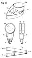
- Figure 8: Embidiments employing illuminated sample application zones
-
DESCRIPTION OF SELECTED EMBODIMENTS
-
For the purposes of promoting an understanding of the principles of the invention,
reference will now be made to the embodiments illustrated in the drawings and
specific language will be used to describe the same. It will nevertheless be
understood that no limitation of the scope of the invention is thereby intended,
such alterations and further modifications in the illustrated device, and such
further applications of the principles of the invention as illustrated therein being
contemplated as would normally occur to one skilled in the art to which the
invention relates. One embodiment of the invention is shown in great detail,
although it will be apparent to those skilled in the art that some of the features
which are not relevant to the invention may not be shown for the sake of clarity.
-
A first general concept of the present invention concerns a body fluid testing device
that incorporates a test media tape. The test media tape holds test media that are
used to collect body fluid samples which are analyzed with a sensor.
Advantageously the test media tape is housed in a cassette so that after the test
media of a cassette are used up a fresh test media cassette can be inserted into the
testing device. The test media tape is indexed before or after each test so that
successive tests can be performed without requiring disposal of the used test media.
The test media can be indexed manually or automatically.
The test medium is a medium which contains a test chemistry that with analyte
from a sample leads to detectable results. For further details of test chemistry and
testing see section "Testing General". Prefereably the test media are designed to
soak up the test fluid sample. This prevents the testing device from becoming
contaminated by body fluid sample. As will be described in more detail lateron it is
preferred to employ a test media tape which comprises a transport tape on which
test media are arranged with free spaces between successive test media. The
preferred arrangement therefor has a structure with regions as follows: tape with
test medium - tape without test medium - tape with test medium - and so on. The
tape can be made e.g. from conventional plastic tape. The test media are attached to
the tape, e.g. by glueing, welding or by use of an adhesive tape.
-
A body fluid testing device (10) according to the present invention is shown in
figure 1A. The drawing of the device shows a housing (11) and a display (12) for
displaying test results as well as instructions of use. At the front end of the device
there can be seen a tip portion (20) over which the test media tape (30) runs. This
tip portion is a first inventive idea of the present invention. A test medium at the
front end of the testing device is exposed by the tip portion in a tip like manner
which facilitates the application of body fluid. The tip portion for this reason at
least partially projects out of the contour of the housing (11) of the testing device to
be accessible for a body portion (e.g. finger or arm).
-
The testing device can be approached to a body surface (e.g. finger or arm) on
which a body fluid sample is located with the tip portion. In order to make the tip
portion easily accessible and visible as the location where sample has to be applied
it is preferred to employ a tip like shape. Easy access and good visibility can be
achieved by a tip portion that changes the direction of movement of the test media
tape by an angle of more than 60 degree, prefereably more than 90 degree.
-
Figure 1B shows a very similar testing device as depicted in figure 1A. While the test
media tape (30) in the embodiment of figure 1A runs from the left to the right side
of the device (or vice versa) in figure 1B the tape runs from the upper side to the
lower side (or vice versa).
-
According to a second inventive concept of the present invention body fluid
application can be further facilitated by illuminating a portion (30') of the test tape
where the body fluid sample has to be applied. For this functionality a translucent
test medium is advantageous. If the test medium, however, is opaque a translucent
portion of the test media tape without test medium applied to it may be employed.
However, most test media for analyte testing as e.g. reflectometric glucose test
media are partially transparent and therefore produce an easily visible lighted area
on the frontside of the test medium when illumination from the backside is made
and the layer of test medium is not too thick. The artisan in this field knows how to
make test media which transmit enough light that an illumination from the
backside can easily be seen by a user. It is preferred to illuminate the backside of the
test media tape with colored light (e.g. red or green) so that a better visible
illumination results as by illuination with white light would result.
-
The second inventive concept of the present invention includes the user guidance
by illuminating a portion of the test medium or a test element to which sample
fluid has to be applied. As already described above illumination is made when the
device is ready to receive sample fluid. Further the size of the illuminated area on
the frontside of the test medium advantageously can be chosen to indicate the size
of the test medium which needs to be filled with sample fluid to allow proper
analysis. The user therefore can visually control whether he has applied enough
sample fluid to the correct position on the test medium. The illumination for user
guidance is made when the test element is positioned in the testing device for
sample reception. For illumination the same optics as for optical evaluation can be
used. However, if it is desired to indicate the size of sample fluid to be applied to
the test medium it is preferred to employ a separate light source for this purpose.
-
There is a certain connection between the area wetted by sample fluid and the
recognition whether proper analysis can be done. Test media require a certain
amount of sample volume to allow a reliable measurement. The amount of liquid
which is necessary depends on a number of factors as the test chemistry, test
architecture (layer structure with e.g. additional layers for removal of cells etc.),
optics or electrodes and so on. For an actual testing device where these factors are
fixed and the test medium is standardized the minimum amount of sample fluid
needed for reliable measurement is a fixed number. On the other side the area on
the test medium covered by sample fluid is related to the volume of sample fluid. In
case of a non-absorbing test medium a drop is formed with an area that is
dependent on surface tension. Based upon known surface conditions the area
therefore can be related to the sample volume. In case of an absorbing test medium
the absorption capacity per area detemines the area which is wetted by a certain
amount of fluid. The wetted area on the test medium therefore is closely related to
the volume of fluid applied.
The testing device according to this second inventive idea illuminates an area of the
test medium which becomes wetted when a sample volume equal or above the
volume required for proper analysis is applied. The user therefore can visually
control whether the fluid sample he has applied covers the whole illuminated area
or not. This allows a twofold control
- if enough fluid has been applied
- if the body fluid sample has been applied to the correct location on the test
medium.
Further it is advantageous to combine the user guidance by illumination with
monitoring of fluid application to the test medium. Such monitoring is possible by
optical or electrochemical detection. In an optical method light reflected from the
test medium is detected and a change in intensity is monitored to detect sample
fluid application. In an electrical process conductivity or capacity can be monitored
to detect sample application. The before mentioned changes of measurement
signals can be evaluated to give one or more of the following information:
- whether sample has been applied to the test medium,
- whether the sample has been applied to the correct position on the test medium
- whether the applied sample volume is sufficient.
-
Illumination at the tip portion further may serve to guide the user through the use
process of the testing device. Blinking e.g. may indicate that the testing device is
ready for sample fluid to be applied and a constant light or a deenergization of the
light may show that sample has been successfully applied.
-
Illumination as described above can be implemented by employing a separate light
source which is controlled by a control unit. However, in case of optical
measurement as common in this field the light source for measurement can
advantageously be employed for illumination of the test medium at the sampling
position as well.
-
A testing device according to the above embodiment further has a control unit for
controlling activation of the light source for illumination of the test medium. The
control unit activates the light source when the instrument waits for fluid sample to
be applied to the test medium. Illumination in this sense does not only mean
constant illumination but also includes e.g. blinking. The illumination may remain
until the user shuts down the testing device but it is preferred that the control unit
deactivates illumination or changes the type of illumination when proper
application of fluid to the test medium is detected (as described above). However,
in case of optical evaluation of the test medium the illumination may be activated
again for measuring an analyte concentration in the fluid sample.
-
The user guidance by illumination can be employed advantageously in
embodiments where the test media portion for application of sample fluid is
located at a tip. In this geometric setup the user can see the light when he is
applying sample to the test medium. By sake of the tip geometry the user can
visually monitor the application process, especially the approaching of the tip
portion by a body portion on which body fluid is located. Due to illumination at
the tip portion light is not shielded by the approaching body portion until shortly
before contacting the illuminated area with sample fluid.
-
However, the user guidance by illumination of the sample application area can be
used in a much wider field as shown in figures 8 to 10.
-
Figure 8 depicts a reflectometric blood glucose testing device (200) which is sold
under the name AccuChek Active. The device has a port (210) for receiving
individual test elements (250). A suitable test element is shown from the upper side
and the backside. When the test element is arranged for measurement a test
element (250) is located in the port (210) so that the backside of the test medium
(251) is positioned above an optical sensing unit (211). The test medium changes
color in dependence on analyte concentration in a sample fluid (270) which is
applied to the upper side of the test medium. The backside of the test medium can
be optically accessed through a recess in the test element base (252) to allow optical
reading. In prior art systems illumination of the test medium is made for reading
only but not for user guidance. Therefore the present invention claims the concept
of user guidance for sample application by illuminating an area on the test
medium. Advantageously in this context the indication of sample fluid size and
guidance for positioning of the sample fluid by use of the illumination site as well
as the illuminated area size as described above can be employed Further it is
preferred in this embodiment to employ a continuous illumination of the sample
application zone which remains until sample is applied.
-
In Figure 9 there is shown the illumination for user guidance concept in the context
of a light guiding test element (300). The test element has the shape of a tube (301)
made of light guiding material (e.g. a clear plastic as polymethylmethacrylate). On
the front side of the tube there is located a test medium (301) onto which sample
fluid needs to be applied for analysis. The backside of the tube is connected to an
optics (not shown) for guiding light (305) into the tube and for receiving light
reflected from the backside of the test medium (302). For user guidance
illumination can be made in the same way by guiding light into the light guiding
test element so that the test medium onto which fluid has to be applied is
illuminated. It has to be understood that this invention is not restricted to tube
shaped test elements but that it also can be applied to other light guiding test
elements as well. Contrary to the conventional use of such light guiding test
elements illumination is activated when the testing device is ready for sample
reception and the illumination indicates to the user that sample has to be applied.
-
Figure 10 shows the illumination for user guidance in a further context. The test
element (400) is a capillary fill test element having a capillary channel (401) formed
in a layer (402) of material. This layer (401) or a layer of material located above or
below have light guiding properties. When light (405) is directed into the back end
of the test element the frontside (406) of the test element is illuminated. Sample
fluid is applied to the capillary end (407) at the frontside and the sample fluid
moves through the capillary channel to the test medium (403). The test medium
e.g. can be evaluated electrochemically by electrodes contacting the test medium.
Alternatively the test medium can be read optically trough a recess in the test
element. In this embodiment the sample is not directly applied to the test medium
itself but to a transport capillary. The illumination indicates a portion of the test
element to which sample has to be applied. However, the sample has to be applied
to the capillary which is indicated by the illuminated end of the test element located
next to the capillary end.
-
Figure 2 shows the application of body fluid (40) to an exposed portion of test
media tape (30) at the convex tip portion (20) of a testing device. From the figures
it can be seen how the tip portion facilitates sample application.
-
Figure 3 depicts two tip portion (20) embodiments in more detail. The
embodiment of figure 3A has an exposure portion (21) and a guidance portion
(22). The guidance portion (22) has a channel formed by two rails (23) which guide
a test media tape for travelling on the bottom surface (24) of the channel. The
exposure portion (21) preferably has no protruding elements as e.g. rails which
could hinder contacting of the test media tape sited in this area with body fluid.
The tape supporting surface (25) further has a recess (26) as depicted in figure 3A.
In this recess a sensor can be disposed for evaluation of the test media tape. Suitable
sensors are optical sensors including a light source and a detector for measuring
light reflected from the test medium. Further a sensor unit with electrodes can be
disposed in that recess (26) for contacting electrochemical test media at the
exposure portion (21).
-
It is preferred to locate the sensing portion of a sensor unit at the exposure portion
since measurement can be done right after the sample has been applied and no tape
transport is necessary before measurement. However, it is also possible to locate a
measurement unit for analyte concentration measurement at another position to
which the test medium is moved after sample has been applied to it.
-
In figure 3B a tip portion (20) similar to that of figure 3A is shown. However, the
guidance portion (22) has a circumferentially closed channel through which the
test media tape runs. The tape is therefore guided by the inner walls of that channel
to run over the exposure portion (21'). The exposure portion (21') is different to
that of figure 3A in that it has no recess but a sensing unit is integrated into it. This
can be accomplished by e.g. making a part or the whole exposure portion (21')
from clear plastic to allow light to shine through it and to transmit light reflected
from the test medium located over exposure portion (21') to a detector.
-
The tip portions (20) of figures 3A and 3B can be a part of the testing device (10) or
they can be a part of a test media tape cassette.
-
Figure 4 shows a cut through tip portion (20) of figure 3B. In this perspective the
guidance portion (22') in form of two channels left and right from the exposure
portion (21') can be seen. The tip portion is made from an opaque plastic with an
illumination channel (27) and a detection channel (28). At the proximal end of the
illumination channel (27) a light source (50) (e.g. a LED) is disposed to illuminate
a test medium located above the distal end of the illumination channel. Light
reflected from the test medium enters the detection channel (28) at its distal end
and is received by a detector (60) (e.g. a photovoltaic element or a photodiode) at
the proximal end of the detection channel. Illumination channel and / or detection
channel can be empty channels or channels in which optical elements as e.g. lenses
or light transmitting fibers are located.
-
Figure 4 further shows an important effect of the tip portion. The test media tape
lies on the exposure portion (21') and enters this portion in the direction shown by
a first arrow (ED) and leaves the portion in direction of a second arrow (LD). Right
hand to the tip there is shown a vector diagram in which the starting point of these
two direction vectors are located on the same spot. It can be seen that there is an
angle between leaving direction (LD) and entering direction (ED). It has been
found particularly suited to provide handling ease by employing an angle α above
60°, prefereably above 90°. It has to be understood that this definition is not
restricted to embodiments where the test media tape rests on the exposure portion.
This definition is based on the change of direction which is imposed on the test
media tape imposed by the tip portion, prefereably within the exposure portion.
-
Figures 5A, B, C and D show possible arrangements of supply and storage portions
for test media tape relative to the tip portion (20). In figure 5A a test media storage
reel (110) is located behind the tip portion (20) and behind the storage reel a
supply reel (100) is located. The positions of the supply and the storage reel can be
exchanged vice versa while still having this in-line arrangement. The in-line
arrangement is advantageous if a slim testing device is desired.
-
Figure 5B depicts an embodiment where a supply (100) and a storage reel (110) are
arranged side by side with the tip portion (20) in between. This arrangement is
advantageous if the tip portion (20) is part of the instrument so that the test media
tape (30) can be spanned over the tip portion during or after insertion of a test
media cassette into the testing device.
-
Figure 5C depicts a further alternative with two reels in a supply portion and two
reels in the storage portion (110). The arrows in all these schematic diagrams
indicate the direction of movement of the test media tape during subsequent use of
portions of test medium. The embodiment of figure 5D is advantageous if a slim
design of the testing device is desired. A view to figure 1 shows that a slim design
facilitates user handling.
-
In figure 5D there is shown an embodiment where the supply and storage reel are
arranged coaxially. As can be seen this arrangement is very space efficient. Between
the reels and the tip portion (20) there is located an optical unit (55) for evaluating
a test medium (30') located at the tip portion.
-
In figure 6A there can be seen a test media cassette (90) for insertion into a testing
device. The cassette has a housing (91) in which a supply reel (100) and a storage
reel (110) are located. The cassette further comprises a tip portion (20). The test
media tape (30) runs over the distal end (outer end) of the tip portion. The test
media tape portion on the tip portion is located outside the housing (91) and
therefore exposed to the surrounding. At the inner end (distal end) of the tip
portion the cassette has a first recess (93) in its housing for receiving an optics
belonging to the testing device. It is advantageous that the cassette has rollers or
pins (92) for guiding the test media tape through the cassette. In the depicted
embodiment the cassette has a second recess (94) for receiving a drive wheel of the
testing device. The storage reel (110) has a recess in its center and engagement
elements for receving and engaging said drive wheel. It has to be understood that
the drive wheel recess is an option only. Alternative an axis of the storage wheel can
be employed which belongs to the cassette an which can be driven from outside the
cassette.
The rotational axis (95) of the storage reel belongs to the cassette of the depicted
embodiment. However, this axis can also be realized by a recess for receiving an
axis belonging to the testing device. The supply reel (100) (or a drive which drives
that reel) should have a tension control that controls tension of the test media tape
and therefore avoids a too loose or too much tensioned test media tape.
-
As already mentioned the test media tape is exposed to the environment at the tip
portion. Most test media are, however, destroyed or altered by humidity, sunlight
etc.. Therefore measures have to be taken to shelter the test media. A first measure
is to package the whole cassette (90) before use such that a contact with humidity
from the surrounding is prevented. This can be achieved by e.g. a blister package.
Bearing in mind that the cassette housing (91) can be made as a body closed against
humidity with the exception of the tip region embodiments can be contemplated
which employ a humidity proof cover over the tip region which can be removed
prior to use of the cassette.
-
Figure 6B shows a testing device (10) with the cassette (90) of figure 6A being
inserted into it. The testing device has a drive wheel (150) engaging the storage reel
(110) of the cassette. The drive wheel is driven by a motor (not shown). Alternative
the drive wheel can be actuated manually by a user. When a motor is employed this
can be actuated by a drive unit which controls and coordinates the transfer of test
media into the sampling position on the tip portion (20) and measurement. As
already mentioned it is advantageous to conduct an evaluation of a test medium
wetted with sample fluid when the test medium is located at the tip portion.
However, it is also possible to transfer a test medium wetted with sample fluid away
from that position into a spatially distinct evaluation postition, e.g. within the
cassette. In figure 6B there can be further seen an optics (160) which belongs to the
testing device and which enters the first recess (93) when the cassette (90) is
inserted into the testing device (10). In case of optical measurement it is necessary
to couple the device optics (160) with the tip portion (20). This e.g. can be
accomplished by employing a tip portion as an optical transparent tip or to include
optical fibers into an otherwise opaque tip (see e.g. figure 4). The device optics
(160) can be made by use of fiber optics to which a light source and a detector are
coupled.
Figure 6B further shows an important measure to shelter test media against
humidity and other influences when the cassette is already in use. As can be seen
the distance of test media on the tape is chosen in a way that a second test medium
(30") is located inside the cassette housing when a first test medium (30') is located
on the tip portion (20). Further it is preferred if the distance between successive test
media is so large that a successive test element is still within the sheltering housing
when the actual test element is already located within the storage portion of the
device. Even more advantageous the distance between two successive test media is
so large that the second test medium is covered by overlying tape while the first test
medium is on the tip portion. Hence the tape overlying the second test medium is
sheltering it.
Figure 6B further shows a channel (96) inside the cassette located between tip
portion and supply portion. This channel is the only connection beween the
storage section (97) and the outside. Through this channel the test media tape runs
from the storage reel on its way to the tip portion. Channel (96) serves to limit
convections into the channel which would introduce humid air into the storage
section in which fresh (unused) test media are stored. Further this channel serves as
a diffusion channel which puts a resistance on the diffusion of humidity into the
storage section.
-
Figure 7 shows an alternative to the embodiment of figure 6. Here the differences
between these two concepts will be described and for similarities reference is made
to the description of figure 6.
Figure 7A depicts a test media cassette (90') having a supply reel (100) and a
storage reel (110). The cassette has a first recess (93') for receiving an optics. This
embodiment also has a second recess (94') for receiving a drive wheel similar to
that described above. However, contraty to figure 6 the cassette of figure 7 has no
tip portion.
Figure 7B shows the cassette of figure 7A inserted into a testing device (10'). As can
be seen the testing device has a tip portion which is coupled to an evaluation optics
of the testing device. As apparent from figures 7A and 7B the cassette can be
inserted into the testing device without user handling steps for guiding the test
media tape onto the tip portion. With insertion the exposed portion of test media
tape is already located in front of the tip portion (20') belonging to the testing
device. From figure 7C it can be seen that the tip portion (20') is moved so that test
media tape from the exposed portion is moved outside the device housing. Test
media therefore can be accessed very easily by a user at the tip of the tip portion
which extends outside the contour of the testing device.