EP1426149A1 - Razor blade assembly - Google Patents
Razor blade assembly Download PDFInfo
- Publication number
- EP1426149A1 EP1426149A1 EP04003532A EP04003532A EP1426149A1 EP 1426149 A1 EP1426149 A1 EP 1426149A1 EP 04003532 A EP04003532 A EP 04003532A EP 04003532 A EP04003532 A EP 04003532A EP 1426149 A1 EP1426149 A1 EP 1426149A1
- Authority
- EP
- European Patent Office
- Prior art keywords
- blade assembly
- razor blade
- assembly according
- housing
- razor
- Prior art date
- Legal status (The legal status is an assumption and is not a legal conclusion. Google has not performed a legal analysis and makes no representation as to the accuracy of the status listed.)
- Granted
Links
- 230000001050 lubricating effect Effects 0.000 claims description 10
- 230000000712 assembly Effects 0.000 description 8
- 238000000429 assembly Methods 0.000 description 8
- 230000007935 neutral effect Effects 0.000 description 7
- 230000000694 effects Effects 0.000 description 4
- 239000004033 plastic Substances 0.000 description 4
- 210000004209 hair Anatomy 0.000 description 3
- 239000013536 elastomeric material Substances 0.000 description 2
- 230000000295 complement effect Effects 0.000 description 1
- 230000001815 facial effect Effects 0.000 description 1
- 230000002452 interceptive effect Effects 0.000 description 1
- 230000013011 mating Effects 0.000 description 1
- 239000002184 metal Substances 0.000 description 1
- 238000002156 mixing Methods 0.000 description 1
- 230000002250 progressing effect Effects 0.000 description 1
- 230000000284 resting effect Effects 0.000 description 1
- 229920001169 thermoplastic Polymers 0.000 description 1
- 239000004416 thermosoftening plastic Substances 0.000 description 1
Images


Classifications
-
- B—PERFORMING OPERATIONS; TRANSPORTING
- B26—HAND CUTTING TOOLS; CUTTING; SEVERING
- B26B—HAND-HELD CUTTING TOOLS NOT OTHERWISE PROVIDED FOR
- B26B21/00—Razors of the open or knife type; Safety razors or other shaving implements of the planing type; Hair-trimming devices involving a razor-blade; Equipment therefor
- B26B21/08—Razors of the open or knife type; Safety razors or other shaving implements of the planing type; Hair-trimming devices involving a razor-blade; Equipment therefor involving changeable blades
- B26B21/14—Safety razors with one or more blades arranged transversely to the handle
- B26B21/22—Safety razors with one or more blades arranged transversely to the handle involving several blades to be used simultaneously
-
- B—PERFORMING OPERATIONS; TRANSPORTING
- B26—HAND CUTTING TOOLS; CUTTING; SEVERING
- B26B—HAND-HELD CUTTING TOOLS NOT OTHERWISE PROVIDED FOR
- B26B21/00—Razors of the open or knife type; Safety razors or other shaving implements of the planing type; Hair-trimming devices involving a razor-blade; Equipment therefor
- B26B21/40—Details or accessories
- B26B21/4012—Housing details, e.g. for cartridges
-
- B—PERFORMING OPERATIONS; TRANSPORTING
- B26—HAND CUTTING TOOLS; CUTTING; SEVERING
- B26B—HAND-HELD CUTTING TOOLS NOT OTHERWISE PROVIDED FOR
- B26B21/00—Razors of the open or knife type; Safety razors or other shaving implements of the planing type; Hair-trimming devices involving a razor-blade; Equipment therefor
- B26B21/08—Razors of the open or knife type; Safety razors or other shaving implements of the planing type; Hair-trimming devices involving a razor-blade; Equipment therefor involving changeable blades
- B26B21/14—Safety razors with one or more blades arranged transversely to the handle
- B26B21/22—Safety razors with one or more blades arranged transversely to the handle involving several blades to be used simultaneously
- B26B21/222—Safety razors with one or more blades arranged transversely to the handle involving several blades to be used simultaneously with the blades moulded into, or attached to, a changeable unit
- B26B21/225—Safety razors with one or more blades arranged transversely to the handle involving several blades to be used simultaneously with the blades moulded into, or attached to, a changeable unit the changeable unit being resiliently mounted on the handle
-
- B—PERFORMING OPERATIONS; TRANSPORTING
- B26—HAND CUTTING TOOLS; CUTTING; SEVERING
- B26B—HAND-HELD CUTTING TOOLS NOT OTHERWISE PROVIDED FOR
- B26B21/00—Razors of the open or knife type; Safety razors or other shaving implements of the planing type; Hair-trimming devices involving a razor-blade; Equipment therefor
- B26B21/40—Details or accessories
- B26B21/4012—Housing details, e.g. for cartridges
- B26B21/4031—Housing details, e.g. for cartridges characterised by special geometric shaving parameters, e.g. blade span or exposure
Definitions
- the invention relates to razor blade assemblies for mounting on handles via pivotal connections.
- a well-known razor blade assembly e.g., as shown in U.S. Patent Nos. 4,573,266 and 4,586,255, employs a spring-biased guard member at the front of the assembly, a lubricating-strip cap portion at the back, and two spring-biased blade members between them
- U.S. Patent No. 5,249,361 shows a similar razor blade assembly with a fixed-guard. Both versions of the assembly have rails and circular surfaces for making pivotal, connections with shell bearings on razor handles. Spring-biased cam followers on the razor handles interact with cam surfaces on the bottoms of the razor blade assemblies so as to bias the assemblies to neutral positions relative to the handles.
- the assembly can pivot forward (clockwise) or backward (counterclockwise) from the neutral position relative to the handle, and the blades can move within the housing relative to the skin surface in order to follow the contours of the skin surface during shaving.
- the shell bearings provide pivoting about an axis located between and above the two resiliently moving blades (considering their unloaded state as a reference).
- the pivot axis is located at the center of the slot in which the primary (forewardmost) blade supporting member is disposed and at the top of a clip that retains the blade members to the cartridge housing.
- the pivot axis is provided above the cutting edges of the blades and above the housing.
- This pivot axis location may therefore be referred to as being located "in the face" (that is, above the skin-engaging members) during shaving of a face.
- the razor blade assemblies are discarded after a number of shaves, and replacement razor blade assemblies are used with the handles containing the shell bearings and the spring-biased cam followers.
- the same razor handle can be used with both versions of the razor blade assembly, because they both have the same size rails and circular surfaces.
- the invention features, in general, a razor blade assembly for mounting on a handle via a pivotal connection.
- the razor blade assembly includes a housing that carries three blade members, each having a leading edge, and has a guard portion at the front, a cap structure at the rear, a blade member mounting portion between the guard portion and the cap structure, top surfaces at the sides of the blade member mounting portion, and arcuate bearing surfaces below the blade member mounting portion that slidably engage surfaces of the pivotal connecting structure of the handle.
- the arcuate surfaces have radii of curvature so as to provide pivotal mounting on the handle about a pivot axis that is located in a region defined by an imaginary boundary extending from the leading edge of the first blade member to the leading edge of the second blade member when both are in the unloaded condition (which corresponds to the raised at-rest position, assuming resiliently mounted blade members), extending upward and rearward from the second leading edge to slightly above the upper surface of the housing at a location in front of the-leading edge of the third blade member, extending along and slightly above the upper surface of the housing to a position in front of the first leading edge, extending downward and forward to a location within the guard portion below and forward of the leading edge of the first blade member, and extending from the location within the guard portion upward and rearward to the first leading edge. So locating the pivot axis permits three blade members to be accommodated while still maintaining good shave characteristics.
- the cap structure has a lubricious shaving aid received in a cavity at the rear of the housing, and the pivot axis is located on the skin surface during shaving (preferably near the leading edge of the middle blade member) so that the blade assembly can rotate, via the arcuate bearing surfaces engaging shell bearings on the razor handle, through a desired arc of travel of up to about 45° without the shell bearings impinging into the housing, particularly avoiding an interference in the region of the shaving aid.
- the housing has clips at the ends of the housing that retain the blade members on the housing. At least two of the blade members have leading edges that are sharpened cutting edges.
- the blade members have blade cutting edge members mounted on an L-shaped base and platform member. The blade members are mounted in the housing for resilient movement during shaving.
- the arcuate bearing surfaces have a constant radius of curvature.
- the guard member has upwardly extending ribs with tips located above a plane passing through the leading edges. Shaving forces, are balanced equally over the cutting edges by locating the pivot axis at a plane through two of the cutting edges and close to the midpoint between skin-engaging surfaces of the cap and guard.
- the invention features, in general, a razor blade assembly for mounting on a handle having a pivotal connecting structure and a spring-biased cam follower.
- the razor blade assembly includes a housing having a guard portion at the front, a cap portion at the rear, a blade member mounting portion between the guard portion and the cap portion, and structure that mates with the handle pivotal connecting structure so that the housing moves through an arc between a forward pivot stop position and a rearward pivot stop position.
- the housing also has a cam surface with an apex that is located to provide an at-rest position other than a position midway between the forward pivot stop position and the rearward pivot stop position.
- the apex can be located near the front of the housing to cause the assembly to be biased upward (also referred to as "forward") on the razor handle, whereby the arcuate undersurface of the cartridge is brought to the forward pivot stop position, so that the cap contacts the skin first and then shaving forces orient the cartridge, and provides low initial angles of attack of the blade.
- the apex can be located near the rear of the housing so that the assembly is biased downward (also referred to as "rearward") on the razor handle, whereby the arcuate undersurface of the cartridge is brought to the rear pivot stop position, so that a higher initial angle of attack of the blades is provided and the guard contacts the skin first.
- the apex can also be provided at a location providing both forward and rearward pivoting but to different extents in the two directions.
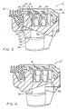
- Fig. 1 is a perspective view of a razor blade assembly according to the invention.
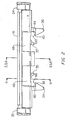
- Fig. 2 is a rear elevation of the Fig. 1 razor blade assembly.
- Fig. 3 is a vertical partial sectional view, taken at 3-3 of Fig. 2, of the Fig. 1 razor blade assembly.
- Fig. 4 is a vertical partial sectional view, taken at 4-4 of Fig. 2, of the Fig. 1 razor blade assembly.
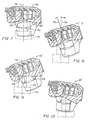
- Fig. 5 is a vertical partial sectional view, taken at 5-5 of Fig. 2, of an alternative embodiment of the Fig. 1 razor blade assembly.
- Fig. 6 is a vertical partial sectional view, taken at 6-6 of Fig. 2, of another alternative embodiment of the Fig. 1 razor blade assembly.
- Fig. 7 is a vertical sectional view of the Fig. 3 razor blade assembly with portions of a handle and its cam follower shown in phantom in an at-rest position.
- Fig. 8 is a vertical sectional view of the Fig. 7 razor blade assembly and handle with the razor blade assembly shown in a pivoted position.
- Fig. 9 is a vertical sectional view of the Fig. 5 razor blade assembly with portions of a handle and its cam follower shown in phantom in an at rest position.
- Fig. 10 is a vertical sectional view of the Fig. 9 razor blade assembly and handle with the razor blade assembly shown in a pivoted position.
- Razor blade assembly 10 for mounting on a handle having a pivotal connecting structure as described in U.S. Patent No. 4,573,266.
- Razor blade assembly 10 includes plastic housing 12, guard member 14 at the front of housing 12, cap member 2 at the rear of the housing 12 and having disposed therein lubricating strip cap member 16 at the rear of housing 12, and three blade members 18, 20 and 22 in a blade mounting portion of housing 12 between guard member 14 and lubricating cap member 16.
- Primary blade 18 is nearest the guard
- secondary blade 20 is next nearest the guard
- tertiary blade 22 is furthest from the guard.
- the cap member 2 has an upper surface portion 3 and a rear surface portion 4.
- the cap member 2 is provided with an elongated cavity 5 defined in part by the upper surface portion 3 and the rear surface portion 4.
- Lubricating cap member 16 has a base 15 received in the cavity 5 at the rear of housing 12.
- Lubricating cap member 16 has a top surface 17 blending into a rear surface 19 to generally form a continuation of the cap member upper and rear surface portions.
- Blades 18, 20, 22 each include a separate leading edge carrying portion 23 that is supported on an L-shaped member having a platform 25 and a base portion 27.
- Each leading edge carrying portion 23 has a respective leading edge 29 generally directed towards the guard member 14.
- the leading edges 29 can be formed as sharpened cutting edges.
- Metal clips 24, 26 at the two sides of housing 12 retain the ends of blades 18, 20, and 22.
- Blade members 18, 20, 22 could be formed fixed in the housing 12, but preferably they are resiliently mounted, and are biased to their raised, at-rest positions (that is, not loaded by shaving forces) shown in Fig. 1 via plastic leaf-spring arms 28, 30, 32 that are integral with plastic housing 12 and extend in from both sides thereof.
- Guard 14 is a unitary molded member formed of bottom base portion 58, of rigid plastic, and upper portion 60 of elastomeric material.
- Bottom base portion 58 has a substantially V-shaped cross sectional portion 62 and a forwardly projecting platform portion 64 which has a plurality of openings spaced along its length.
- Upper portion 60 is molded contiguous to base portion 58 and is made of a thermoplastic elastomeric material chosen to provide flexibility for ribs 66, as is described in detail in U.S. Patent No. 5,249,361, which is hereby incorporated by reference
- the tips of ribs 66 are in a plane that is about half-way between the plane that passes through the cutting edges of the blade members and the top of clips 24, 26.
- the raised tips provide effective shielding of the blades.
- the tips also exert a traction force on the skin to stretch it and raise hairs before the primary blade, thus reducing overall cutting effort.
- extensions 34, 36 are located at the bottom of housing 12 and carry inwardly extending opposed curved rails 38, 40 having respective curved surfaces 42, 44.
- the undersurfaces 46, 48 of housing 12 are similarly curved and provide, with extensions 34, 36, a pivotal connecting structure that mates with components on the handle, as is described in detail in U.S. Patent Nos. 4,488,357; 4,498,235; 4,492,025; 4,573,266; 4,586,255, and 4,756,082 which are hereby incorporated by reference for disclosure of shell bearing connections between a razor blade assembly and a handle.
- the blade assembly rails 38, 40, in conjunction with undersurfaces 46, 48 of housing 12 define arcuate slots 98, 100 adapted to receive razor handle shell bearings (not shown).
- arcuate slot 98 disposed tangent between curved undersurface 46 and curved rail 38 is shown with extended centerline 99 extending therefrom.
- the shell bearings comprise a pivot mounting structure adapted to cooperate with the above described blade assembly pivot mounting structure to facilitate pivotal connection of the blade assembly to the razor handle assembly.
- the mating structure on the handle shell bearing (not shown) has stop surfaces that prevent, as best seen in Figs. 1 and 3, rear extension surface 39 from further “upward” travel to provide a forward pivot stop position and front extension surface 41 from further “downward” travel to provide a rearward pivot stop position.
- the shell bearings on the handle (not shown) have recesses that mate with stop surfaces 35, 37 formed on the respective curved undersurfaces 46, 48 to complement the rearward pivot stop position to prevent further "downward” travel.
- the top surfaces of rails 38, 40 and housing undersurfaces 46, 48 have radii of curvature about pivot axis P located at the cutting edge of the second blade 20.
- the curved surfaces 42, 44 of extensions 34, 36 are similarly curved about the pivot axis P.
- the top curved surfaces of the rails 38, 40 have radii of curvature of 0.2291 "(5.82 mm), shown by the arrow extending from pivot axis P in Fig. 3, and the undersurfaces 46, 48 have radii of curvature of 0.1921" (4.88 mm), shown by the arrow extending from pivot axis P in Fig.
- the inter-blade span common for resiliently moving blades is between 0.5mm and 2.0mm, and typically about 1.5 mm.
- the larger blade member mounting portion of assembly 10 has the effect of pushing back the lubricating strip cap member in order to conveniently accommodate it on the cartridge and causing it to occupy a region that would otherwise be occupied by the arcuate surfaces of the pivotal connection of existing two-blade assemblies, and in particular giving rise to an interference with the shell bearings of the razor handle if the cartridge were rotated through the typical about 40° to 45° arc of rotation permitted with a Sensor-type cartridge.
- the larger blade member mounting region is accommodated, while maintaining the lubricating strip cap member and the same radius of curvature, by lowering the pivot axis from the top of the clips between the two blades (as in the existing two-blade structures taken as a reference) to the cutting edge of the middle blade member, and still maintaining a permissible overall rotation through an arc of up to about 45° without a geometric interference arising.
- cam surface 50 is formed in the bottom of housing 12.
- Surface 50 has two oppositely inclined surfaces of the same size and an apex 52 located at a position midway between the front and the back of cam surface 50.
- Cam surface 50 permits assembly 10 to pivot forward or rearward to the same extent during shaving, and is adapted to receive a cam follower to bias the cartridge within the range of overall rotation through a 40° to 45° arc.
- razor blade assembly 10' has a cam surface 54 with apex 56 located at the front end thereof but otherwise has the same structure as assembly 10.
- Cam surface 54 is contoured so that cam follower 70 is compressed to the same extent that it is compressed when it follows cam surface 50 of the Fig. 3 embodiment in both the at-rest position and the fully pivoted stop position along the arc of rotation. Because the cam follower is spring-loaded, there is a similar restoring force on the cartridge of the embodiments of Figs. 3 or 5 at their respective initial and fully rotated positions.
- Figs. 7 and 9 show the at-rest positions for razor blade assemblies 10, 10', and Figs. 8 and 10 show their respective pivoted positions that can result during shaving.
- the distance from the cam surface 54 to the shell bearing at the at-rest position or at the fully rotated position is the same as that from the cam surface 50.
- the distance from the pivot axis P to the location of tangency of the cam follower 70 on the cam surface 54 is the same as that distance to the location of tangency of cam follower 70 on cam surface 50.
- cam surface 54 at the location of tangency of the cam follower 70 is displaced in vertical distance relative to the location of tangency at the at-rest position by the same amount as at the same location on the cam surface 50 tangent to cam follower 70.
- the at-rest position is a neutral position; in this position a plane through the cutting edges is perpendicular to axis 74 along which cam follower 70 slides.
- spring-biased cam follower 70 rests at apex 52 in the position in which the follower is most extended from handle 72.
- Assembly 10 can be rotated forward (“upward”) or rearward (“downward”) from this at-rest position.
- Fig. 8 shows razor blade assembly 10 pivoted upward (counter clockwise in Fig. 6) to a forward position which could result from downward forces primarily on guard 14 during a shaving operation.
- Reference axis 75 constructed through the pivot axis perpendicular to the blade assembly 10 has been pivoted relative to reference axis 74 through an arc of rotation ⁇ of about 22.5°.
- razor blade assembly 10' is tilted forward ("upwardly-biased") in its at rest position, with spring-biased cam follower 70 resting at apex 56 in the position in which the follower is most extended from handle 72.
- Assembly 10' can only be rotated downward (clockwise in Fig. 9) to a rearward position from this at-rest position, as is shown in Fig. 10, and cannot be rotated forward ("upward”).
- the upwardly-biased orientation presents a lower effective angle of attack of the blades initially, to provide more initial comfort and less likelihood of nicking the skin being shaved.
- blade members 18, 20, 22 are independently resiliently movable with respect to housing 12, and housing 12 pivots with respect to handle 72 with the result that the cutting edges tend to follow the contours of the skin surface. All three blade members can have sharp cutting edges to cut body or facial hairs at three locations. Furthermore, it may be advantageous to set the blades to have different exposures, e.g. increasing exposure progressing from the primary blade to the tertiary blade, as is described in PCT Publication WO 95/09071, which is hereby incorporated by reference. Alternatively, one of the blades, e.g.
- the secondary or tertiary one could be formed with a relatively narrow blunt edge designed to not penetrate hairs, as is described in detail in PCT Publication WO 92/17322, which is hereby incorporated by reference.
- one of the blades e.g., the primary or secondary one, could be formed dull to act solely as a resiliently movable guard.
- the pivot axis P is in a preferred embodiment at the cutting edge of the secondary blade.
- the pivot axis P is then located on the skin surface during shaving.
- housing 12 pivots about pivot axis P, which is desirably located at the skin surface, thereby avoiding chatter of the blades and providing effective tracking of the three blades on the face or skin surfaces being shaved, while permitting the blade assembly 10 to rotate via the arcuate slots 98, 100 engaging shell bearings on the razor handle through a desired arc of motion of up to about 40° to 45°.
- the housing 12 does not intersect, in the sense of giving rise to a geometric interference, the arcuate surface.
- the pivot axis P is not rearward of the tertiary blade and into the face, in order to avoid in effect pushing all the blades into the face, which is less likely to avoid nicks.
- Pivot axis P could also be moved forward of the cutting edge of the second blade member to the cutting edge of the first blade member and could be located at positions above these two blade members up to slightly above the upper surface of the housing so long as the blade assembly 10 rotates on the arcuate slots 98, 100 engaging shell bearings on the razor handle through a desired arc of motion, e.g. through up to about 40° to 45°, without the shell bearings (which extend along an imaginary arcuate surface extending from the arcuate slots 98, 100) impinging on the housing 12, particularly on the cap member 2 in a region of the lubricating strip cap member 16, or other necessary structures. If the lubricating strip cap member 16 were moved or changed in shape, e.g.
- pivot axis higher relative to the blades could be employed.
- the pivot axis could also be moved to a lower position in front of the first blade (to a location within the guard member).
- the pivot axis should be located in a region defined by boundary 80 shown on Fig. 3 in dashed lines so long as the radius of curvature is maintained without interfering with necessary structures.
- Boundary 80 extends from the first cutting edge to the second cutting edge (when both are in the raised position shown in Fig.
- the arcuate surfaces of the housing 12 such as rails 38, 40 and undersurfaces 46, 48 are formed having radii of curvature about any chosen pivot axis P location as their center, whereas the numerical value of the radius of curvature of each respective arcuate surface is maintained the same.
- the pivot axis P could be located on or above a plane through at least two cutting edges of the blades in an unloaded (at-rest) condition (which corresponds to a raised position for resiliently moving blades) and at or forward of a location approximately midway between the functional skin engaging surfaces of cap member 2 and guard member 14 (where loading occurs on a distributed area as the cap or guard, reference is considered from the midpoint of the respective skin engaging surface).
- Locating the pivot axis P at the plane through cutting edges and substantially close to the midpoint between the cap and guard contributes to evenly balancing the shaving forces applied to the cutting edges and advantageously maintaining all the shaving elements, namely the guard, the cap and the blade members, on the skin surface during a shaving operation.
- razor blade assembly 10' has an at rest position at which it is biased upwardly (tilted forward). This provides a lower effective angle of the blades to the face when the face is first contacted and limits rotation to only the rearward angular direction. The skin being shaved is first contacted by the cap surface; then shaving forces orient assembly 10' to rotate it to a good shaving angle and orientation. (In common cases, the position could be one rotated less than is shown in Fig. 10). When so upwardly biased, the blade edges are not initially normal to the razor handle. The angle at which the blades are initially presented to the face is lower, with the effect that there is more comfort initially and less chatter results.
- Apex 56 could be moved to a location between the forward position (as in Fig. 5) and the neutral position (shown for apex 52 in Fig. 3), providing a small amount of forward pivot and a much larger amount of rearward pivot. Neutral positioning or upwardly biased produce similar shaving results.
- razor blade assembly 10" has a cam surface 58 with apex 59 located at the rear end thereof but otherwise has the same structure as assembly 10 or 10'.
- assembly 10" When mounted onto the handle, assembly 10" has an at-rest position having an opposite incline than that shown in Fig. 9. This is referred to as "downwardly biased" (tilted rearward) in its at rest position.
- the blade assembly could only be rotated upward (counter clockwise in Fig. 9).
- the guard contacts the face first and one gets the feel of the guard stretching the skin before shaving. While there would be a higher initial blade angle, the guard would provide shielding of the blades.
- apex may also be desirable to move the apex to a location between the rearward position (as in Fig. 6) and the neutral position (apex 52 in Fig. 3), to provide a partially downwardly biased initial orientation. Applicant believes that biased down would produce similar shaving results to neutral positioning.
Abstract
Description
- The invention relates to razor blade assemblies for mounting on handles via pivotal connections.
- A well-known razor blade assembly, e.g., as shown in U.S. Patent Nos. 4,573,266 and 4,586,255, employs a spring-biased guard member at the front of the assembly, a lubricating-strip cap portion at the back, and two spring-biased blade members between them U.S. Patent No. 5,249,361 shows a similar razor blade assembly with a fixed-guard. Both versions of the assembly have rails and circular surfaces for making pivotal, connections with shell bearings on razor handles. Spring-biased cam followers on the razor handles interact with cam surfaces on the bottoms of the razor blade assemblies so as to bias the assemblies to neutral positions relative to the handles. During shaving, the assembly can pivot forward (clockwise) or backward (counterclockwise) from the neutral position relative to the handle, and the blades can move within the housing relative to the skin surface in order to follow the contours of the skin surface during shaving. In commercial embodiments of these razor blade assemblies (available under the Sensor and Sensor Excel trade designations from The Gillette Company), the shell bearings provide pivoting about an axis located between and above the two resiliently moving blades (considering their unloaded state as a reference). In particular, the pivot axis is located at the center of the slot in which the primary (forewardmost) blade supporting member is disposed and at the top of a clip that retains the blade members to the cartridge housing. Thus, the pivot axis is provided above the cutting edges of the blades and above the housing. This pivot axis location may therefore be referred to as being located "in the face" (that is, above the skin-engaging members) during shaving of a face. The razor blade assemblies are discarded after a number of shaves, and replacement razor blade assemblies are used with the handles containing the shell bearings and the spring-biased cam followers. The same razor handle can be used with both versions of the razor blade assembly, because they both have the same size rails and circular surfaces.
- It is desired to improve shaving performance by providing three blades within a cartridge. However, simply accommodating a third blade in a widened conventional twin blade cartridge housing, which also supports skin-engaging guard and cap surfaces, results in a geometric interference between the shell bearings of the handle and the cartridge housing as the cartridge rotates in response to shaving forces.
- In one aspect, the invention features, in general, a razor blade assembly for mounting on a handle via a pivotal connection. The razor blade assembly includes a housing that carries three blade members, each having a leading edge, and has a guard portion at the front, a cap structure at the rear, a blade member mounting portion between the guard portion and the cap structure, top surfaces at the sides of the blade member mounting portion, and arcuate bearing surfaces below the blade member mounting portion that slidably engage surfaces of the pivotal connecting structure of the handle. The arcuate surfaces have radii of curvature so as to provide pivotal mounting on the handle about a pivot axis that is located in a region defined by an imaginary boundary extending from the leading edge of the first blade member to the leading edge of the second blade member when both are in the unloaded condition (which corresponds to the raised at-rest position, assuming resiliently mounted blade members), extending upward and rearward from the second leading edge to slightly above the upper surface of the housing at a location in front of the-leading edge of the third blade member, extending along and slightly above the upper surface of the housing to a position in front of the first leading edge, extending downward and forward to a location within the guard portion below and forward of the leading edge of the first blade member, and extending from the location within the guard portion upward and rearward to the first leading edge. So locating the pivot axis permits three blade members to be accommodated while still maintaining good shave characteristics.
- In preferred embodiments the cap structure has a lubricious shaving aid received in a cavity at the rear of the housing, and the pivot axis is located on the skin surface during shaving (preferably near the leading edge of the middle blade member) so that the blade assembly can rotate, via the arcuate bearing surfaces engaging shell bearings on the razor handle, through a desired arc of travel of up to about 45° without the shell bearings impinging into the housing, particularly avoiding an interference in the region of the shaving aid. The housing has clips at the ends of the housing that retain the blade members on the housing. At least two of the blade members have leading edges that are sharpened cutting edges. The blade members have blade cutting edge members mounted on an L-shaped base and platform member. The blade members are mounted in the housing for resilient movement during shaving. The arcuate bearing surfaces have a constant radius of curvature. The guard member has upwardly extending ribs with tips located above a plane passing through the leading edges. Shaving forces, are balanced equally over the cutting edges by locating the pivot axis at a plane through two of the cutting edges and close to the midpoint between skin-engaging surfaces of the cap and guard.
- In another aspect, the invention features, in general, a razor blade assembly for mounting on a handle having a pivotal connecting structure and a spring-biased cam follower. The razor blade assembly includes a housing having a guard portion at the front, a cap portion at the rear, a blade member mounting portion between the guard portion and the cap portion, and structure that mates with the handle pivotal connecting structure so that the housing moves through an arc between a forward pivot stop position and a rearward pivot stop position. The housing also has a cam surface with an apex that is located to provide an at-rest position other than a position midway between the forward pivot stop position and the rearward pivot stop position. The apex can be located near the front of the housing to cause the assembly to be biased upward (also referred to as "forward") on the razor handle, whereby the arcuate undersurface of the cartridge is brought to the forward pivot stop position, so that the cap contacts the skin first and then shaving forces orient the cartridge, and provides low initial angles of attack of the blade. Alternatively the apex can be located near the rear of the housing so that the assembly is biased downward (also referred to as "rearward") on the razor handle, whereby the arcuate undersurface of the cartridge is brought to the rear pivot stop position, so that a higher initial angle of attack of the blades is provided and the guard contacts the skin first. The apex can also be provided at a location providing both forward and rearward pivoting but to different extents in the two directions.
- Other advantages and features of the invention will be apparent from the following description of preferred embodiments thereof and from the claims.
- Fig. 1 is a perspective view of a razor blade assembly according to the invention.
- Fig. 2 is a rear elevation of the Fig. 1 razor blade assembly.
- Fig. 3 is a vertical partial sectional view, taken at 3-3 of Fig. 2, of the Fig. 1 razor blade assembly.
- Fig. 4 is a vertical partial sectional view, taken at 4-4 of Fig. 2, of the Fig. 1 razor blade assembly.
- Fig. 5 is a vertical partial sectional view, taken at 5-5 of Fig. 2, of an alternative embodiment of the Fig. 1 razor blade assembly.
- Fig. 6 is a vertical partial sectional view, taken at 6-6 of Fig. 2, of another alternative embodiment of the Fig. 1 razor blade assembly.
- Fig. 7 is a vertical sectional view of the Fig. 3 razor blade assembly with portions of a handle and its cam follower shown in phantom in an at-rest position.
- Fig. 8 is a vertical sectional view of the Fig. 7 razor blade assembly and handle with the razor blade assembly shown in a pivoted position.
- Fig. 9 is a vertical sectional view of the Fig. 5 razor blade assembly with portions of a handle and its cam follower shown in phantom in an at rest position.
- Fig. 10 is a vertical sectional view of the Fig. 9 razor blade assembly and handle with the razor blade assembly shown in a pivoted position.
- Referring to Figs. 1-3, there is shown
razor blade assembly 10 for mounting on a handle having a pivotal connecting structure as described in U.S. Patent No. 4,573,266.Razor blade assembly 10 includesplastic housing 12,guard member 14 at the front ofhousing 12,cap member 2 at the rear of thehousing 12 and having disposed therein lubricatingstrip cap member 16 at the rear ofhousing 12, and threeblade members housing 12 betweenguard member 14 and lubricatingcap member 16.Primary blade 18 is nearest the guard,secondary blade 20 is next nearest the guard, andtertiary blade 22 is furthest from the guard. Thecap member 2 has anupper surface portion 3 and arear surface portion 4. Thecap member 2 is provided with anelongated cavity 5 defined in part by theupper surface portion 3 and therear surface portion 4. Lubricatingcap member 16 has abase 15 received in thecavity 5 at the rear ofhousing 12. Lubricatingcap member 16 has a top surface 17 blending into arear surface 19 to generally form a continuation of the cap member upper and rear surface portions.Blades edge carrying portion 23 that is supported on an L-shaped member having aplatform 25 and abase portion 27. Each leadingedge carrying portion 23 has a respective leadingedge 29 generally directed towards theguard member 14. The leadingedges 29 can be formed as sharpened cutting edges.Metal clips housing 12 retain the ends ofblades Blade members housing 12, but preferably they are resiliently mounted, and are biased to their raised, at-rest positions (that is, not loaded by shaving forces) shown in Fig. 1 via plastic leaf-spring arms plastic housing 12 and extend in from both sides thereof. -
Guard 14 is a unitary molded member formed ofbottom base portion 58, of rigid plastic, andupper portion 60 of elastomeric material.Bottom base portion 58 has a substantially V-shaped crosssectional portion 62 and a forwardlyprojecting platform portion 64 which has a plurality of openings spaced along its length.Upper portion 60 is molded contiguous tobase portion 58 and is made of a thermoplastic elastomeric material chosen to provide flexibility forribs 66, as is described in detail in U.S. Patent No. 5,249,361, which is hereby incorporated by reference The tips ofribs 66 are in a plane that is about half-way between the plane that passes through the cutting edges of the blade members and the top ofclips - It is desirable to provide three blade members to provide more closeness and control over shaving performance by providing a greater degree of precision adjustment in determining the shaving geometry, for example, different blade exposures can be set, or different spans set between groups of two adjacent elements that contact the skin, as described in detail in PCT Publication WO 95/09071, which is hereby incorporated by reference for disclosure of shaving geometry. However, simply adding a third blade could disadvantageously increase drag forces, which is believed due to the cutting force being applied to more blades. It is desirable that the
housing 12 be large enough to accommodate not only the three blade members, but also the above-describedguard 14 withelastomeric fins 66 and lubricatingcap member 16 to reduce the drag forces. - Referring to Fig. 2,
extensions housing 12 and carry inwardly extending opposedcurved rails 38, 40 having respectivecurved surfaces undersurfaces housing 12 are similarly curved and provide, withextensions - Referring to Figs. 2, 3 and 4, it will be seen that the blade assembly rails 38, 40, in conjunction with
undersurfaces housing 12 definearcuate slots arcuate slot 98 disposed tangent betweencurved undersurface 46 andcurved rail 38 is shown with extended centerline 99 extending therefrom. The shell bearings comprise a pivot mounting structure adapted to cooperate with the above described blade assembly pivot mounting structure to facilitate pivotal connection of the blade assembly to the razor handle assembly. - The mating structure on the handle shell bearing (not shown) has stop surfaces that prevent, as best seen in Figs. 1 and 3, rear extension surface 39 from further "upward" travel to provide a forward pivot stop position and front extension surface 41 from further "downward" travel to provide a rearward pivot stop position. As best seen in Figs. 2 and 3, the shell bearings on the handle (not shown) have recesses that mate with stop surfaces 35, 37 formed on the respective
curved undersurfaces - As is indicated in Figs. 3 and 4, the top surfaces of
rails 38, 40 andhousing undersurfaces second blade 20. The curved surfaces 42, 44 ofextensions rails 38, 40 have radii of curvature of 0.2291 "(5.82 mm), shown by the arrow extending from pivot axis P in Fig. 3, and theundersurfaces razor blade assembly 10 to be used with existing Sensor handles, a large number of which have already been purchased by the consuming public, even though the blade member mounting portion is extended substantially in width from front to rear to accommodate the third blade member. The substantially widened blade member mounting portion results from the presence of the additional blade member, where the blade members are positioned with an inter-blade span or spacing that is typical to that on conventional Sensor-type cartridges. The provision of three blade members advantageously permits the span between pairs of adjacent blade members to be set differently, as described in detail in PCT Publication WO 95/09071, which is hereby incorporated by reference for disclosure of shaving geometry. The inter-blade span common for resiliently moving blades is between 0.5mm and 2.0mm, and typically about 1.5 mm. The larger blade member mounting portion ofassembly 10 has the effect of pushing back the lubricating strip cap member in order to conveniently accommodate it on the cartridge and causing it to occupy a region that would otherwise be occupied by the arcuate surfaces of the pivotal connection of existing two-blade assemblies, and in particular giving rise to an interference with the shell bearings of the razor handle if the cartridge were rotated through the typical about 40° to 45° arc of rotation permitted with a Sensor-type cartridge. The larger blade member mounting region is accommodated, while maintaining the lubricating strip cap member and the same radius of curvature, by lowering the pivot axis from the top of the clips between the two blades (as in the existing two-blade structures taken as a reference) to the cutting edge of the middle blade member, and still maintaining a permissible overall rotation through an arc of up to about 45° without a geometric interference arising. - Still referring to Fig. 3,
cam surface 50 is formed in the bottom ofhousing 12.Surface 50 has two oppositely inclined surfaces of the same size and an apex 52 located at a position midway between the front and the back ofcam surface 50. Cam surface 50permits assembly 10 to pivot forward or rearward to the same extent during shaving, and is adapted to receive a cam follower to bias the cartridge within the range of overall rotation through a 40° to 45° arc. - Referring to Fig. 5, razor blade assembly 10' has a
cam surface 54 withapex 56 located at the front end thereof but otherwise has the same structure asassembly 10.Cam surface 54 is contoured so thatcam follower 70 is compressed to the same extent that it is compressed when it followscam surface 50 of the Fig. 3 embodiment in both the at-rest position and the fully pivoted stop position along the arc of rotation. Because the cam follower is spring-loaded, there is a similar restoring force on the cartridge of the embodiments of Figs. 3 or 5 at their respective initial and fully rotated positions. - Referring to Figs. 7-10, Figs. 7 and 9 show the at-rest positions for
razor blade assemblies 10, 10', and Figs. 8 and 10 show their respective pivoted positions that can result during shaving. The distance from thecam surface 54 to the shell bearing at the at-rest position or at the fully rotated position is the same as that from thecam surface 50. At the at-rest position, the distance from the pivot axis P to the location of tangency of thecam follower 70 on thecam surface 54 is the same as that distance to the location of tangency ofcam follower 70 oncam surface 50. At the fully rotated position, thecam surface 54 at the location of tangency of thecam follower 70 is displaced in vertical distance relative to the location of tangency at the at-rest position by the same amount as at the same location on thecam surface 50 tangent tocam follower 70. - For razor blade assembly 10 (Fig. 7), the at-rest position is a neutral position; in this position a plane through the cutting edges is perpendicular to
axis 74 along whichcam follower 70 slides. In the at-rest position, spring-biasedcam follower 70 rests at apex 52 in the position in which the follower is most extended fromhandle 72.Assembly 10 can be rotated forward ("upward") or rearward ("downward") from this at-rest position. - Fig. 8 shows
razor blade assembly 10 pivoted upward (counter clockwise in Fig. 6) to a forward position which could result from downward forces primarily onguard 14 during a shaving operation.Reference axis 75 constructed through the pivot axis perpendicular to theblade assembly 10 has been pivoted relative toreference axis 74 through an arc of rotation ∝ of about 22.5°. - Referring to Fig. 9, razor blade assembly 10' is tilted forward ("upwardly-biased") in its at rest position, with spring-biased
cam follower 70 resting atapex 56 in the position in which the follower is most extended fromhandle 72. Assembly 10' can only be rotated downward (clockwise in Fig. 9) to a rearward position from this at-rest position, as is shown in Fig. 10, and cannot be rotated forward ("upward"). The upwardly-biased orientation presents a lower effective angle of attack of the blades initially, to provide more initial comfort and less likelihood of nicking the skin being shaved. - During shaving,
blade members housing 12, andhousing 12 pivots with respect to handle 72 with the result that the cutting edges tend to follow the contours of the skin surface. All three blade members can have sharp cutting edges to cut body or facial hairs at three locations. Furthermore, it may be advantageous to set the blades to have different exposures, e.g. increasing exposure progressing from the primary blade to the tertiary blade, as is described in PCT Publication WO 95/09071, which is hereby incorporated by reference. Alternatively, one of the blades, e.g. the secondary or tertiary one, could be formed with a relatively narrow blunt edge designed to not penetrate hairs, as is described in detail in PCT Publication WO 92/17322, which is hereby incorporated by reference. Also alternatively, one of the blades, e.g., the primary or secondary one, could be formed dull to act solely as a resiliently movable guard. - The pivot axis P is in a preferred embodiment at the cutting edge of the secondary blade. When the pivot axis P is located at the level of a skin engaging member such as the blade cutting edge, the pivot axis P is then located on the skin surface during shaving. During shaving,
housing 12 pivots about pivot axis P, which is desirably located at the skin surface, thereby avoiding chatter of the blades and providing effective tracking of the three blades on the face or skin surfaces being shaved, while permitting theblade assembly 10 to rotate via thearcuate slots razor blade assembly 10 is thus rotated, for example, throughslot 98 relative to a fixed arcuate surface extending along centerline 99 shown in Fig. 4, thehousing 12 does not intersect, in the sense of giving rise to a geometric interference, the arcuate surface. Having the virtual pivot axis P at or into the face (assuming the face is the surface being shaved) causes the cutting edges to in effect be dragged across the face (as opposed to being pushed into the face) in order to avoid nicks. Advantageously the pivot axis P is not rearward of the tertiary blade and into the face, in order to avoid in effect pushing all the blades into the face, which is less likely to avoid nicks. - Pivot axis P could also be moved forward of the cutting edge of the second blade member to the cutting edge of the first blade member and could be located at positions above these two blade members up to slightly above the upper surface of the housing so long as the
blade assembly 10 rotates on thearcuate slots arcuate slots 98, 100) impinging on thehousing 12, particularly on thecap member 2 in a region of the lubricatingstrip cap member 16, or other necessary structures. If the lubricatingstrip cap member 16 were moved or changed in shape, e.g. by being made very thin, a pivot axis higher relative to the blades could be employed. The pivot axis could also be moved to a lower position in front of the first blade (to a location within the guard member). In general, the pivot axis should be located in a region defined by boundary 80 shown on Fig. 3 in dashed lines so long as the radius of curvature is maintained without interfering with necessary structures. Boundary 80 extends from the first cutting edge to the second cutting edge (when both are in the raised position shown in Fig. 3), extends upward and rearward from the second cutting edge to slightly above the upper surface of the housing at a location in front of the third cutting edge, extends along (and slightly above) the upper surface of the housing to a position in front of the first blade member, extends downward and forward to a location within the guard member below and forward of the first cutting edge, and extends from the location within the guard portion upward and rearward to the first cutting edge. As indicated in Figs. 3 and 4, and discussed hereinabove, the arcuate surfaces of thehousing 12 such asrails 38, 40 andundersurfaces - In order to obtain relatively equally balanced forces over the cutting edges while still permitting the desired arc of cartridge motion, the pivot axis P could be located on or above a plane through at least two cutting edges of the blades in an unloaded (at-rest) condition (which corresponds to a raised position for resiliently moving blades) and at or forward of a location approximately midway between the functional skin engaging surfaces of
cap member 2 and guard member 14 (where loading occurs on a distributed area as the cap or guard, reference is considered from the midpoint of the respective skin engaging surface). Locating the pivot axis P at the plane through cutting edges and substantially close to the midpoint between the cap and guard contributes to evenly balancing the shaving forces applied to the cutting edges and advantageously maintaining all the shaving elements, namely the guard, the cap and the blade members, on the skin surface during a shaving operation. - In the embodiment of Fig. 5, razor blade assembly 10' has an at rest position at which it is biased upwardly (tilted forward). This provides a lower effective angle of the blades to the face when the face is first contacted and limits rotation to only the rearward angular direction. The skin being shaved is first contacted by the cap surface; then shaving forces orient assembly 10' to rotate it to a good shaving angle and orientation. (In common cases, the position could be one rotated less than is shown in Fig. 10). When so upwardly biased, the blade edges are not initially normal to the razor handle. The angle at which the blades are initially presented to the face is lower, with the effect that there is more comfort initially and less chatter results.
Apex 56 could be moved to a location between the forward position (as in Fig. 5) and the neutral position (shown forapex 52 in Fig. 3), providing a small amount of forward pivot and a much larger amount of rearward pivot. Neutral positioning or upwardly biased produce similar shaving results. - Alternatively, in the embodiment of Fig. 6,
razor blade assembly 10" has acam surface 58 withapex 59 located at the rear end thereof but otherwise has the same structure asassembly 10 or 10'. When mounted onto the handle,assembly 10" has an at-rest position having an opposite incline than that shown in Fig. 9. This is referred to as "downwardly biased" (tilted rearward) in its at rest position. In this case the blade assembly could only be rotated upward (counter clockwise in Fig. 9). In this case the guard contacts the face first and one gets the feel of the guard stretching the skin before shaving. While there would be a higher initial blade angle, the guard would provide shielding of the blades. It may also be desirable to move the apex to a location between the rearward position (as in Fig. 6) and the neutral position (apex 52 in Fig. 3), to provide a partially downwardly biased initial orientation. Applicant believes that biased down would produce similar shaving results to neutral positioning. - Other embodiments of the invention are within the scope of the following claims.
Claims (23)
- A razor blade assembly (10) for mounting on a handle having a handle pivoting connecting structure, said assembly including a housing (12) having a guard member (14) at the front, a cap structure (2) at the rear, a blade mounting portion between the guard member (14) and the cap structure (2), upper surfaces (9) at the sides of the blade mounting portion, arcuate bearing surfaces below the blade mounting portion that slidably engage said handle pivoting connecting structure and have radii of curvature so as to provide pivotal mounting on said handle for movement of the blade assembly about a pivot axis (P) located above said arcuate bearing surfaces, characterized in that first, second, and third blade members (18,20,22) are mounted in said blade mounting portion, said first blade member (18) being mounted nearest the guard (14) and the third blade member (22) being mounted nearest the cap (2), said first, second, and third blade members (18, 20, 22) having respective first, second, and third leading edges (29) generally directed toward said guard member (14) and arranged to sequentially contact skin of a surface being shaved during a shaving operation, said leading edges (29) in an unloaded position being lower than said upper surfaces (9) and further characterized in that
said pivot axis (P) is located at a position which permits desired pivotal movement of the blade assembly and in a region defined by a boundary extending at or above a plane through at least two said leading edges (29) in the unloaded position and at or forward of a position approximately midway between the midportion of the skin engaging surface of the guard member (14) and the cap structure (2). - A razor blade assembly according to claim 1, characterized in that said pivot axis (P) is located at or below said upper surfaces of said housing (12) so that said razor blade assembly rotates through an arc of travel of at least 40° about said pivot axis (P) and relative to an imaginary arcuate extension (99) of said arcuate bearing surfaces without said arcuate extension (99) intersecting said housing (12).
- A razor blade assembly according to claim 1 or claim 2, characterized in that the region defined by the boundary (80) does not extend forward beyond a location midway between said first and second leading edges and does not extend rearward beyond a location midway between said second and third leading edges and does not extend above a location halfway between the leading edges (29) and said upper surfaces at the side of said housing (12).
- A razor blade assembly according to claim 1 or claim 2, characterized in that said pivot axis (P) is located at the second leading edge.
- A razor blade assembly according to any of claims 1 to 4, characterized in that said blade members (18,20,22) are resiliently mounted in said blade mounting portion for movement from raised unloaded positions to lowered positions in response to forces encountered during shaving.
- A razor blade assembly according to any of claims 1 to 5, characterized in that at least two of the leading edges (29) are sharpened cutting edges.
- A razor blade assembly according to any of claims 1 to 5, characterized in that the three leading edges (29) are sharpened cutting edges.
- A razor blade assembly according to claim 1 or claim 2, characterized in that said location below and forward of the first leading edge intersects with the guard member.
- A razor blade assembly according to claim 1 or claim 2, characterized in that the region does not extend in front of said first leading edge.
- A razor blade assembly according to claim 1 or claim 2, characterized in that the region does not extend behind said second leading edge nor below said boundary extending from said first leading edge to said second leading edge when both are in the unloaded position.
- A razor blade assembly according to any of claims 1 to 10, characterized in that said assembly further includes clips (24,26) at the sides of said housing (12) that retain said blade members (18,20,22) on said housing (12).
- A razor blade assembly according to any of claims 1 to 11, characterized in that each said blade member (18,20,22) comprises a blade leading edge member (23) mounted on an L-shaped member having a base (27) and a platform (25).
- A razor blade assembly according to claim 1, characterized in that said pivot axis (P) is in the region between said first and second leading edges and said upper surfaces of the housing (12) thereabove.
- A razor blade assembly according to any of claims 1 to 13, characterized in that said arcuate bearing surfaces have a constant radius of curvature.
- A razor blade assembly according to any of claims 1 to 14, characterized in that said housing (12) has stop surfaces (35,37) interacting with said pivoting connecting structure of said handle to provide forward and rearward pivot stop positions.
- A razor blade assembly according to any of claims 1 to 15, characterized in that said guard member (14) has upwardly extending ribs (66) with tips located above a plane passing through said leading edges (29) in the unloaded positions.
- A razor blade assembly according to claim 16, characterized in that said tips are about halfway between said plane passing through said leading edges (29) and a plane passing through said upper surfaces.
- A razor blade assembly according to any of claims 1 to 17, characterized in that said cap structure (2) further comprises a lubricating strip member (16).
- A razor blade assembly according to any of claims 1 to 18, characterized in that said arcuate bearing surfaces have radii of curvature less than 6 mm.
- A razor blade assembly according to claim 19, characterized in that said arcuate bearing surfaces have radii of curvature greater than 4 mm.
- A razor blade assembly according to any of claims 1 to 20, characterized in that said arcuate bearing surfaces further comprise curved undersurfaces (46,48) of said housing (12) and opposing curved rails (38,40), said rails (38,40) depending from said housing (12) below said blade mounting portion.
- A razor blade assembly according to claim 1, characterized in that said pivot axis (P) is located substantially at the midway position.
- A razor blade assembly according to any preceding claim, characterized in that said handle further includes a spring-biased cam follower (70) and said arcuate bearing surfaces further provide for movement along an arc between a forward pivot stop position and a rearward pivot stop position, the position midway between said forward and rearward pivot stop positions being a midway position, and in that said housing (12) further includes a cam surface (54) having an apex (56) located relative to said housing pivotal connecting structure to provide an at-rest position at a location other than said midway position and to permit resilient movement away from said at-rest position against spring bias force of said cam follower (70) in response to pivotal forces encountered during shaving.
Applications Claiming Priority (3)
| Application Number | Priority Date | Filing Date | Title |
|---|---|---|---|
| US08/630,053 US5661907A (en) | 1996-04-10 | 1996-04-10 | Razor blade assembly |
| EP97908006A EP0900134B1 (en) | 1996-04-10 | 1997-03-04 | Razor blade assembly |
| US630053 | 2000-08-01 |
Related Parent Applications (2)
| Application Number | Title | Priority Date | Filing Date |
|---|---|---|---|
| EP97908006A Division EP0900134B1 (en) | 1996-04-10 | 1997-03-04 | Razor blade assembly |
| EP97908006.6 Division | 1997-10-16 |
Publications (2)
| Publication Number | Publication Date |
|---|---|
| EP1426149A1 true EP1426149A1 (en) | 2004-06-09 |
| EP1426149B1 EP1426149B1 (en) | 2010-04-21 |
Family
ID=24525570
Family Applications (3)
| Application Number | Title | Priority Date | Filing Date |
|---|---|---|---|
| EP04003532A Expired - Lifetime EP1426149B1 (en) | 1996-04-10 | 1997-03-04 | Razor blade assembly |
| EP97908006A Revoked EP0900134B1 (en) | 1996-04-10 | 1997-03-04 | Razor blade assembly |
| EP03013954A Expired - Lifetime EP1356901B9 (en) | 1996-04-10 | 1997-03-04 | Razor blade assembly |
Family Applications After (2)
| Application Number | Title | Priority Date | Filing Date |
|---|---|---|---|
| EP97908006A Revoked EP0900134B1 (en) | 1996-04-10 | 1997-03-04 | Razor blade assembly |
| EP03013954A Expired - Lifetime EP1356901B9 (en) | 1996-04-10 | 1997-03-04 | Razor blade assembly |
Country Status (33)
| Country | Link |
|---|---|
| US (1) | US5661907A (en) |
| EP (3) | EP1426149B1 (en) |
| JP (2) | JP3401016B2 (en) |
| KR (1) | KR100435822B1 (en) |
| CN (1) | CN1135155C (en) |
| AR (1) | AR006573A1 (en) |
| AT (3) | ATE393687T1 (en) |
| AU (1) | AU712664B2 (en) |
| BR (1) | BR9708764A (en) |
| CA (2) | CA2250003C (en) |
| CO (1) | CO4700322A1 (en) |
| CZ (2) | CZ299527B6 (en) |
| DE (5) | DE29724245U1 (en) |
| DK (2) | DK0900134T3 (en) |
| EG (1) | EG22098A (en) |
| ES (3) | ES2343683T3 (en) |
| HK (2) | HK1016118A1 (en) |
| HU (1) | HU222060B1 (en) |
| ID (1) | ID16576A (en) |
| IL (1) | IL126358A (en) |
| MY (1) | MY120115A (en) |
| NO (2) | NO320575B1 (en) |
| NZ (2) | NZ504242A (en) |
| PL (1) | PL183343B1 (en) |
| PT (1) | PT102365B (en) |
| RO (1) | RO120763B1 (en) |
| RS (1) | RS49554B (en) |
| RU (1) | RU2189308C2 (en) |
| SK (2) | SK286923B6 (en) |
| TR (1) | TR199802023T2 (en) |
| TW (1) | TW343169B (en) |
| UA (1) | UA46841C2 (en) |
| WO (1) | WO1997037818A1 (en) |
Families Citing this family (119)
| Publication number | Priority date | Publication date | Assignee | Title |
|---|---|---|---|---|
| US6161288A (en) * | 1993-02-22 | 2000-12-19 | Andrews; Edward A. | Four blade bi-directional razor structure with flexible guard system |
| US5661907A (en) * | 1996-04-10 | 1997-09-02 | The Gillette Company | Razor blade assembly |
| US5794343A (en) * | 1997-05-12 | 1998-08-18 | The Gillette Company | Razor blade assembly |
| US6473970B1 (en) | 1997-10-20 | 2002-11-05 | American Safety Razor Company | Razor blade cartridge with lubricating flow paths |
| US6430818B1 (en) | 1998-02-06 | 2002-08-13 | American Safety Razor Company | Shaving cartridge |
| US6161287A (en) | 1998-04-24 | 2000-12-19 | The Gillette Company | Razor blade system |
| US6032372A (en) * | 1998-06-22 | 2000-03-07 | Dischler; Louis | Intrinsically fenced safety razor head |
| US6055731A (en) * | 1998-12-23 | 2000-05-02 | Wheel Technology Ltd. | Razor with convex blade assembly |
| US6112412A (en) * | 1999-04-21 | 2000-09-05 | Warner-Lambert Company | Razor assembly and cartridge having improved wash-through |
| US6138361A (en) * | 1999-04-21 | 2000-10-31 | Warner-Lambert Company | Pivotable razor assembly and cartridge |
| US6182366B1 (en) | 1999-04-21 | 2001-02-06 | Warner-Lambert Company | Flexible razor assembly and cartridge |
| US6772523B1 (en) | 1999-04-21 | 2004-08-10 | Eveready Battery Company, Inc. | Pivotable and flexible razor assembly and cartridge |
| US6651342B1 (en) | 2000-02-29 | 2003-11-25 | The Gillette Company | Shaving razor and blade unit with improved guard |
| US6675479B1 (en) | 2000-02-29 | 2004-01-13 | The Gillette Company | Shaving razor and blade unit with improved guard |
| US6629475B1 (en) * | 2000-07-18 | 2003-10-07 | The Gillette Company | Razor blade |
| US7200942B2 (en) * | 2001-03-28 | 2007-04-10 | Eveready Battery Company, Inc. | Safety razor with pivot point shift from center to guard-bar under applied load |
| EP2017044A1 (en) * | 2001-04-27 | 2009-01-21 | Eveready Battery Company, Inc. | Wet razor with four blades, and cartridge therefor |
| DE60203153T2 (en) | 2001-10-22 | 2006-01-26 | Eveready Battery Co., Inc. | shaving |
| US7210229B2 (en) * | 2002-04-24 | 2007-05-01 | Eveready Battery Company, Inc. | Razor cartridge |
| US20050015991A1 (en) * | 2002-04-24 | 2005-01-27 | Eveready Battery Company, Inc. | Razor cartridge |
| DE60209976T2 (en) * | 2002-10-08 | 2006-09-14 | The Gillette Co., Boston | Shaving system for performing multiple shaving actions |
| US20070101574A1 (en) * | 2002-10-08 | 2007-05-10 | Royle Terence G | Shaving system for performing multiple shaving actions |
| US20040128835A1 (en) * | 2002-10-21 | 2004-07-08 | Eveready Battery Company, Inc. | Bidirectional shaving cartridge and razor including same |
| US7086160B2 (en) * | 2002-10-21 | 2006-08-08 | Eveready Battery Company, Inc. | Bidirectional shaving implement |
| AU2004218016A1 (en) * | 2003-02-28 | 2004-09-16 | Eveready Battery Company, Inc. | Shaving implement having improved pivot axis location |
| TWI333545B (en) * | 2003-04-02 | 2010-11-21 | Cholestech Corp | Adhered membranes retaining porosity and biological activity |
| US7617607B2 (en) | 2003-07-21 | 2009-11-17 | The Gillette Company | Shaving razors and other hair cutting assemblies |
| GB2406537B (en) * | 2003-07-21 | 2006-09-06 | Gillette Co | Safety razors |
| GB2408010B (en) * | 2003-11-17 | 2007-03-28 | Knowledge & Merchandising Inc | Shaving product |
| KR101228850B1 (en) * | 2003-12-10 | 2013-02-01 | 코닌클리케 필립스 일렉트로닉스 엔.브이. | Shaving head with skin stretching member |
| US9333657B2 (en) * | 2004-01-26 | 2016-05-10 | Koninklijke Philips N.V. | Safety razor apparatus having a pivotable grip portion |
| US20050198830A1 (en) * | 2004-03-11 | 2005-09-15 | Walker Vincent P. | Shaving cartridges and razors |
| US7669335B2 (en) | 2004-03-11 | 2010-03-02 | The Gillette Company | Shaving razors and shaving cartridges |
| US7690122B2 (en) | 2004-03-11 | 2010-04-06 | The Gillette Company | Shaving razor with button |
| US8104184B2 (en) | 2004-03-11 | 2012-01-31 | The Gillette Company | Shaving cartridges and razors |
| GB2413980A (en) * | 2004-05-12 | 2005-11-16 | Ian Stephen Bell | Razor head |
| US8033023B2 (en) * | 2004-10-20 | 2011-10-11 | The Gillette Company | Shaving razors and cartridges |
| US20060162165A1 (en) * | 2005-01-24 | 2006-07-27 | Faye Villalobos | Long handle disposable razor |
| EP1937444B1 (en) * | 2005-09-14 | 2013-04-17 | Eveready Battery Company, Inc. | Blade mounting members for a razor cartridge |
| US8061237B2 (en) * | 2005-10-26 | 2011-11-22 | The Gillette Company | Manufacturing razor blades |
| US8607667B2 (en) * | 2005-10-26 | 2013-12-17 | The Gillette Company | Manufacturing razor blades |
| US7578217B2 (en) * | 2005-10-26 | 2009-08-25 | The Gillette Company | Manufacturing razor blades |
| US7331107B2 (en) * | 2005-12-20 | 2008-02-19 | Eveready Battery Company, Inc. | Pivot axis for a shaving cartridge |
| US7882640B2 (en) * | 2006-03-29 | 2011-02-08 | The Gillette Company | Razor blades and razors |
| US20070227008A1 (en) † | 2006-03-29 | 2007-10-04 | Andrew Zhuk | Razors |
| US7526869B2 (en) * | 2006-06-08 | 2009-05-05 | Eveready Battery Company, Inc. | Razor handle |
| RU2424109C2 (en) * | 2007-03-02 | 2011-07-20 | Дзе Жиллетт Компани | Razor set with wing-shaped framing of shaving product |
| US20080256800A1 (en) * | 2007-04-20 | 2008-10-23 | Roy Nicoll | Razor cartridge assembly with movable face |
| US9517570B2 (en) | 2007-04-20 | 2016-12-13 | The Gillette Company | Razor cartridge |
| US20080256803A1 (en) * | 2007-04-20 | 2008-10-23 | William Earle Tucker | Razor cartridge pivot axis |
| US20080256801A1 (en) * | 2007-04-20 | 2008-10-23 | O'connor William Thomas | Razor cartridge with front pivot axis |
| GB0716941D0 (en) * | 2007-08-31 | 2007-10-10 | Knowledge & Merchandising Inc | Razor handle |
| EP2123410B1 (en) | 2008-05-23 | 2011-07-27 | Feintechnik GmbH Eisfeld | Razor blade unit with film hinge |
| EP2376261B1 (en) | 2008-12-19 | 2020-04-15 | BIC Violex S.A. | Razor cartridge and mechanical razor comprising such a cartridge |
| US20100313424A1 (en) * | 2009-06-11 | 2010-12-16 | Robert Harold Johnson | Blade cartridge guard comprising an array of flexible fins extending in multiple directions |
| US9193080B2 (en) * | 2009-08-03 | 2015-11-24 | The Gillette Company | Shaving blade unit with self-leveling trimmer |
| KR20110024234A (en) * | 2009-09-01 | 2011-03-09 | 주식회사 도루코 | Razor cartridge |
| AU2010331917A1 (en) | 2009-12-18 | 2012-07-12 | The Gillette Company | Razor cartridge with non-cutting element |
| JP5527762B2 (en) * | 2010-02-04 | 2014-06-25 | 株式会社貝印刃物開発センター | Razor head |
| US20110203120A1 (en) * | 2010-02-23 | 2011-08-25 | Stephen Charles Witkus | Razor cartridge assembly |
| US8931176B2 (en) | 2010-06-09 | 2015-01-13 | The Gillette Company | Blade cartridge guard comprising an array of flexible fins extending in multiple directions |
| USD633253S1 (en) | 2010-06-23 | 2011-02-22 | American Safety Razor | Razor cartridge |
| USD640415S1 (en) | 2010-07-07 | 2011-06-21 | American Safety Razor | Razor cartridge |
| USD648075S1 (en) | 2010-07-07 | 2011-11-01 | American Safety Razor | Razor cartridge |
| USD643977S1 (en) | 2010-10-19 | 2011-08-23 | American Safety Razor | Razor cartridge |
| USD643976S1 (en) | 2010-10-19 | 2011-08-23 | American Safety Razor | Razor cartridge |
| US8732955B2 (en) | 2010-10-20 | 2014-05-27 | The Gillette Company | Shaving razor including a biasing member producing a progressively increasing cartridge return torque |
| US8769825B2 (en) | 2010-10-20 | 2014-07-08 | The Gillette Company | Shaving razor including a biasing member producing a progressively increasing cartridge return torque and handle geometry enhancing control during shaving |
| US8650763B2 (en) | 2010-10-20 | 2014-02-18 | The Gillette Company | Shaving razor providing enhanced control during shaving |
| EP2680702B1 (en) | 2011-02-28 | 2020-02-12 | The Gillette Company LLC | Razor comprising a molded shaving aid composition comprising a pyrithione source |
| US20130160307A1 (en) | 2011-12-22 | 2013-06-27 | Daren Mark Howell | Razor cartridge that rotates about a virtual pivot axis |
| US9193079B2 (en) | 2011-12-22 | 2015-11-24 | The Gillette Company | Linkage mechanism for a razor |
| US20130160306A1 (en) | 2011-12-22 | 2013-06-27 | Daren Mark Howell | Linkage mechanism producing a virtual pivot axis for a razor |
| US9283685B2 (en) | 2012-07-26 | 2016-03-15 | Shavelogic, Inc. | Pivoting razors |
| US9486930B2 (en) | 2012-09-27 | 2016-11-08 | Shavelogic, Inc. | Shaving systems |
| WO2014051842A1 (en) | 2012-09-27 | 2014-04-03 | Shavelogic, Inc. | Shaving systems |
| WO2014051843A1 (en) | 2012-09-28 | 2014-04-03 | Shavelogic, Inc. | Shaving systems |
| US9623575B2 (en) | 2012-12-18 | 2017-04-18 | Shavelogic, Inc. | Shaving systems |
| RU2015135477A (en) | 2013-03-04 | 2017-04-10 | Дзе Жиллетт Компани | Razor with two sliding elements rotatable around one axis |
| JP2016512450A (en) | 2013-03-04 | 2016-04-28 | ザ ジレット コンパニー | Articles for supporting sliding members for use with razors |
| CA2902944A1 (en) | 2013-03-04 | 2014-09-12 | The Gillette Company | Article for carrying a glide member for use with a razor |
| US20140366361A1 (en) * | 2013-06-17 | 2014-12-18 | The Gillette Company | Article for carrying a glide member for use with a razor |
| US20140366381A1 (en) | 2013-06-17 | 2014-12-18 | The Gillette Company | Glide member comrising low to no hygroscopic components for use with a razor |
| EP3950241A1 (en) * | 2013-06-19 | 2022-02-09 | BIC Violex S.A. | A shaving blade assembly comprising a blade unit and a skin contact member and a razor comprising a razor handle and such a shaving blade assembly |
| EP2875916B2 (en) | 2013-11-22 | 2021-09-29 | Koninklijke Philips N.V. | Mounting unit and hair cutting appliance |
| EP2875915B1 (en) | 2013-11-22 | 2019-05-22 | Koninklijke Philips N.V. | Linkage unit and hair cutting appliance |
| US20150158192A1 (en) | 2013-12-09 | 2015-06-11 | Shavelogic, Inc. | Multi-material pivot return for shaving systems |
| JP6395848B2 (en) | 2014-02-27 | 2018-09-26 | ビック・バイオレクス・エス・エー | Shaving blade cartridge, shaver comprising such a shaving blade cartridge, and method of manufacturing such a shaving blade cartridge |
| US11325270B2 (en) | 2014-03-21 | 2022-05-10 | Sl Ip Company Llc | Metal spring return and method |
| US20150273711A1 (en) | 2014-03-26 | 2015-10-01 | The Gillette Company | Razor Comprising A Molded Shaving Aid Composition Comprising A Thermally Resilient Sensate |
| CN104669318B (en) * | 2015-02-03 | 2017-01-04 | 任向荣 | Razor tool tip and assemble method thereof |
| US11117277B2 (en) | 2015-12-01 | 2021-09-14 | Bic-Violex Sa | Shaving razors and shaving cartridges |
| US20170166459A1 (en) * | 2015-12-14 | 2017-06-15 | William Jansen | Externally enhanced electrocoagulation |
| CN105538355B (en) * | 2015-12-22 | 2017-08-15 | 任向荣 | Razor head with clipping function |
| BR112018068899A2 (en) | 2016-03-18 | 2019-01-22 | Personal Care Marketing And Res Inc | razor blade cartridge |
| EP3435959A1 (en) | 2016-04-01 | 2019-02-06 | The Procter and Gamble Company | Oral care compositions containing a gel network phase |
| CN109195755B (en) * | 2016-07-06 | 2021-10-12 | 比克-维尔莱克 | Shaving unit, shaving cartridge and method of manufacture |
| RU2664072C2 (en) * | 2016-11-16 | 2018-08-14 | Леонид Сергеевич Раткин | Cassette with shaving blades |
| US9993931B1 (en) | 2016-11-23 | 2018-06-12 | Personal Care Marketing And Research, Inc. | Razor docking and pivot |
| KR101746387B1 (en) * | 2016-11-24 | 2017-06-14 | 주식회사 도루코 | Unitary razor cartridge |
| US20180297220A1 (en) * | 2017-04-18 | 2018-10-18 | The Gillette Company Llc | Shaving razor system |
| US11141873B2 (en) | 2017-04-18 | 2021-10-12 | The Gillette Company Llc | Shaving razor system |
| US11325271B2 (en) * | 2017-07-20 | 2022-05-10 | Sl Ip Company Llc | Shaving systems |
| EP3546156B1 (en) | 2018-03-30 | 2021-03-10 | The Gillette Company LLC | Razor handle with a pivoting portion |
| CN111770819B (en) * | 2018-03-30 | 2022-09-23 | 吉列有限责任公司 | Shaving razor system including skin interconnect member |
| US11607820B2 (en) | 2018-03-30 | 2023-03-21 | The Gillette Company Llc | Razor handle with movable members |
| BR112020020132A2 (en) | 2018-03-30 | 2021-01-05 | The Gillette Company Llc | HANDLE OF SHAVING OR DEVILING APPLIANCE WITH MOBILE LIMBS |
| CN111867795B (en) | 2018-03-30 | 2022-03-18 | 吉列有限责任公司 | Razor handle |
| CA3091483C (en) * | 2018-03-30 | 2023-01-03 | The Gillette Company Llc | Shaving razor system including skin interconnect member |
| CN111886115B (en) | 2018-03-30 | 2022-04-19 | 吉列有限责任公司 | Razor cartridge |
| EP3774230A1 (en) | 2018-03-30 | 2021-02-17 | The Gillette Company LLC | Razor handle with a pivoting portion |
| WO2019191178A1 (en) | 2018-03-30 | 2019-10-03 | The Gillette Company Llc | Razor handle with movable members |
| US11691307B2 (en) | 2018-03-30 | 2023-07-04 | The Gillette Company Llc | Razor handle with a pivoting portion |
| USD874061S1 (en) | 2018-03-30 | 2020-01-28 | The Gillette Company Llc | Shaving razor cartridge |
| WO2019191345A1 (en) | 2018-03-30 | 2019-10-03 | The Gillette Company Llc | Razor handle with a pivoting portion |
| USD884970S1 (en) | 2019-02-27 | 2020-05-19 | PCMR International Ltd. | Razor cartridge guard |
| USD884971S1 (en) | 2019-02-27 | 2020-05-19 | Pcmr International Ltd | Razor cartridge |
| USD884969S1 (en) | 2019-02-27 | 2020-05-19 | Pcmr International Ltd | Combined razor cartridge guard and docking |
| US11000960B1 (en) | 2020-11-16 | 2021-05-11 | Personal Care Marketing And Research, Inc. | Razor exposure |
Citations (10)
| Publication number | Priority date | Publication date | Assignee | Title |
|---|---|---|---|---|
| US3935639A (en) | 1973-03-01 | 1976-02-03 | The Gillette Company | Safety razor |
| GB2096519A (en) * | 1981-04-09 | 1982-10-20 | Warner Lambert Co | Pivotal razor |
| US4488357A (en) * | 1982-09-17 | 1984-12-18 | The Gillette Company | Safety razor |
| US4498235A (en) * | 1982-09-17 | 1985-02-12 | The Gillette Company | Razor blade assembly |
| US4573266A (en) * | 1982-09-17 | 1986-03-04 | The Gillette Company | Razor blade assembly |
| US4586255A (en) | 1984-10-15 | 1986-05-06 | The Gillette Company | Razor blade assembly |
| WO1989001394A1 (en) * | 1987-08-07 | 1989-02-23 | Conversy Francois Leon | Razor comprising a handle and a head articulated to the latter |
| WO1993010947A1 (en) * | 1991-11-27 | 1993-06-10 | The Gillette Company | Razors |
| US5249361A (en) | 1992-05-13 | 1993-10-05 | The Gillette Company | Guard for razor blade assembly |
| WO1995009071A1 (en) * | 1993-09-29 | 1995-04-06 | The Gillette Company | Safety razors |
Family Cites Families (23)
| Publication number | Priority date | Publication date | Assignee | Title |
|---|---|---|---|---|
| FR1060261A (en) * | 1951-07-17 | 1954-03-31 | Mechanical razor | |
| US3842502A (en) * | 1973-12-21 | 1974-10-22 | Warner Lambert Co | Shaving unit for safety razor |
| US3938247A (en) * | 1974-03-05 | 1976-02-17 | The Gillette Company | Shaving system with pivotal head |
| US3950849A (en) * | 1974-07-23 | 1976-04-20 | The Gillette Company | Razor with rotatably mounted shaving unit |
| US4026016A (en) * | 1975-05-12 | 1977-05-31 | The Gillette Company | Razor blade assembly |
| GB1591095A (en) * | 1976-11-16 | 1981-06-17 | Wilkinson Sword Ltd | Shaving units |
| US4270268A (en) * | 1979-12-07 | 1981-06-02 | The Gillette Company | Razor blade assembly |
| US4308663A (en) * | 1979-12-31 | 1982-01-05 | Warner-Lambert Company | Razor handle with latch for pivotable cartridge |
| SE431359B (en) * | 1982-06-14 | 1984-01-30 | Stal Laval Turbin Ab | GASTURBINANLEGGNING |
| US4587729A (en) * | 1982-09-17 | 1986-05-13 | The Gillette Company | Safety razor |
| US4492025A (en) * | 1982-09-17 | 1985-01-08 | The Gillette Company | Razor handle assembly |
| US4756082A (en) * | 1987-05-12 | 1988-07-12 | Apprille Jr Domenic V | Razor blade assembly and handle therefor |
| US4785534A (en) * | 1987-12-07 | 1988-11-22 | The Gillette Company | Razor |
| US4932122A (en) * | 1987-12-21 | 1990-06-12 | The Gillette Company | Safety razor blade assembly |
| US4831731A (en) * | 1988-04-07 | 1989-05-23 | Mirel Elits | Multiple blade safety razor |
| DE8811355U1 (en) * | 1988-09-08 | 1988-10-20 | Wilkinson Sword Gmbh, 5650 Solingen, De | |
| DE69120900T2 (en) * | 1990-06-11 | 1997-02-13 | Gillette Co | SHAVER |
| US5050301A (en) * | 1990-09-19 | 1991-09-24 | The Gillette Company | Razor assembly |
| US5067238A (en) * | 1990-09-28 | 1991-11-26 | The Gillette Company | Shaving system |
| GB9106860D0 (en) * | 1991-04-02 | 1991-05-22 | Gillette Co | Safety razor |
| GB9125262D0 (en) * | 1991-11-27 | 1992-01-29 | Gillette Co | Razor with blade protection means |
| US5546660A (en) * | 1994-09-30 | 1996-08-20 | Warner-Lambert Company | Dynamic razor head |
| US5661907A (en) * | 1996-04-10 | 1997-09-02 | The Gillette Company | Razor blade assembly |
-
1996
- 1996-04-10 US US08/630,053 patent/US5661907A/en not_active Expired - Lifetime
-
1997
- 1997-03-04 CA CA002250003A patent/CA2250003C/en not_active Expired - Lifetime
- 1997-03-04 HU HU9902871A patent/HU222060B1/en not_active IP Right Cessation
- 1997-03-04 EP EP04003532A patent/EP1426149B1/en not_active Expired - Lifetime
- 1997-03-04 NZ NZ504242A patent/NZ504242A/en active IP Right Revival
- 1997-03-04 IL IL12635897A patent/IL126358A/en not_active IP Right Cessation
- 1997-03-04 ES ES04003532T patent/ES2343683T3/en not_active Expired - Lifetime
- 1997-03-04 ES ES97908006T patent/ES2227673T3/en not_active Expired - Lifetime
- 1997-03-04 EP EP97908006A patent/EP0900134B1/en not_active Revoked
- 1997-03-04 DE DE29724245U patent/DE29724245U1/en not_active Expired - Lifetime
- 1997-03-04 AT AT03013954T patent/ATE393687T1/en not_active IP Right Cessation
- 1997-03-04 TR TR1998/02023T patent/TR199802023T2/en unknown
- 1997-03-04 RS YUP-436/98A patent/RS49554B/en unknown
- 1997-03-04 CN CNB971937672A patent/CN1135155C/en not_active Expired - Lifetime
- 1997-03-04 DK DK97908006T patent/DK0900134T3/en active
- 1997-03-04 DE DE29724235U patent/DE29724235U1/en not_active Expired - Lifetime
- 1997-03-04 CZ CZ20040782A patent/CZ299527B6/en not_active IP Right Cessation
- 1997-03-04 CA CA002322548A patent/CA2322548C/en not_active Expired - Lifetime
- 1997-03-04 BR BR9708764A patent/BR9708764A/en not_active IP Right Cessation
- 1997-03-04 EP EP03013954A patent/EP1356901B9/en not_active Expired - Lifetime
- 1997-03-04 DE DE69739857T patent/DE69739857D1/en not_active Expired - Lifetime
- 1997-03-04 ES ES03013954T patent/ES2305369T3/en not_active Expired - Lifetime
- 1997-03-04 CZ CZ0305598A patent/CZ296709B6/en not_active IP Right Cessation
- 1997-03-04 PL PL97329246A patent/PL183343B1/en unknown
- 1997-03-04 UA UA98115936A patent/UA46841C2/en unknown
- 1997-03-04 JP JP53618797A patent/JP3401016B2/en not_active Expired - Lifetime
- 1997-03-04 DE DE69738659T patent/DE69738659T2/en not_active Expired - Lifetime
- 1997-03-04 SK SK5025-2006A patent/SK286923B6/en not_active IP Right Cessation
- 1997-03-04 DE DE69730827T patent/DE69730827T2/en not_active Expired - Fee Related
- 1997-03-04 SK SK1381-98A patent/SK286885B6/en not_active IP Right Cessation
- 1997-03-04 DK DK03013954T patent/DK1356901T3/en active
- 1997-03-04 WO PCT/US1997/003361 patent/WO1997037818A1/en not_active Application Discontinuation
- 1997-03-04 RO RO98-01472A patent/RO120763B1/en unknown
- 1997-03-04 RU RU98120352/12A patent/RU2189308C2/en not_active IP Right Cessation
- 1997-03-04 AT AT97908006T patent/ATE276856T1/en not_active IP Right Cessation
- 1997-03-04 AT AT04003532T patent/ATE464985T1/en not_active IP Right Cessation
- 1997-03-04 NZ NZ332202A patent/NZ332202A/en unknown
- 1997-03-04 AU AU19861/97A patent/AU712664B2/en not_active Expired
- 1997-03-04 KR KR10-1998-0708028A patent/KR100435822B1/en not_active IP Right Cessation
- 1997-03-10 TW TW086102953A patent/TW343169B/en not_active IP Right Cessation
- 1997-03-14 ID IDP970822A patent/ID16576A/en unknown
- 1997-03-25 MY MYPI97001247A patent/MY120115A/en unknown
- 1997-04-02 EG EG27097A patent/EG22098A/en active
- 1997-04-09 CO CO97018056A patent/CO4700322A1/en unknown
- 1997-04-09 AR ARP970101399A patent/AR006573A1/en unknown
-
1998
- 1998-10-05 NO NO19984648A patent/NO320575B1/en unknown
-
1999
- 1999-03-24 HK HK99101240A patent/HK1016118A1/en not_active IP Right Cessation
- 1999-09-28 PT PT102365A patent/PT102365B/en not_active IP Right Cessation
-
2002
- 2002-11-14 JP JP2002331128A patent/JP4391739B2/en not_active Expired - Lifetime
-
2004
- 2004-03-11 HK HK04101792A patent/HK1058915A1/en not_active IP Right Cessation
- 2004-06-11 NO NO20042450A patent/NO20042450L/en not_active Application Discontinuation
Patent Citations (10)
| Publication number | Priority date | Publication date | Assignee | Title |
|---|---|---|---|---|
| US3935639A (en) | 1973-03-01 | 1976-02-03 | The Gillette Company | Safety razor |
| GB2096519A (en) * | 1981-04-09 | 1982-10-20 | Warner Lambert Co | Pivotal razor |
| US4488357A (en) * | 1982-09-17 | 1984-12-18 | The Gillette Company | Safety razor |
| US4498235A (en) * | 1982-09-17 | 1985-02-12 | The Gillette Company | Razor blade assembly |
| US4573266A (en) * | 1982-09-17 | 1986-03-04 | The Gillette Company | Razor blade assembly |
| US4586255A (en) | 1984-10-15 | 1986-05-06 | The Gillette Company | Razor blade assembly |
| WO1989001394A1 (en) * | 1987-08-07 | 1989-02-23 | Conversy Francois Leon | Razor comprising a handle and a head articulated to the latter |
| WO1993010947A1 (en) * | 1991-11-27 | 1993-06-10 | The Gillette Company | Razors |
| US5249361A (en) | 1992-05-13 | 1993-10-05 | The Gillette Company | Guard for razor blade assembly |
| WO1995009071A1 (en) * | 1993-09-29 | 1995-04-06 | The Gillette Company | Safety razors |
Also Published As
Similar Documents
| Publication | Publication Date | Title |
|---|---|---|
| EP0900134B1 (en) | Razor blade assembly | |
| US6397473B1 (en) | Shaving system with uniform shaving forces | |
| US6266884B1 (en) | Triple blade safety razor | |
| EP1259359B1 (en) | Shaving razor and blade unit with improved guard | |
| US20030159291A1 (en) | Shaving system with uniform shaving forces | |
| US20040055156A1 (en) | Safety razor | |
| KR20220038279A (en) | razor cartridge | |
| WO1995004637A1 (en) | Dynamic shaving system | |
| EP0262781A1 (en) | Razor head | |
| KR20220038280A (en) | razor cartridge | |
| WO1996032232A1 (en) | Multi-directional dynamic shaving system | |
| RU2782107C1 (en) | Razor cartridge |
Legal Events
| Date | Code | Title | Description |
|---|---|---|---|
| PUAI | Public reference made under article 153(3) epc to a published international application that has entered the european phase |
Free format text: ORIGINAL CODE: 0009012 |
|
| AC | Divisional application: reference to earlier application |
Ref document number: 0900134 Country of ref document: EP Kind code of ref document: P |
|
| AK | Designated contracting states |
Kind code of ref document: A1 Designated state(s): AT BE CH DE DK ES FI FR GB IT LI LU NL SE |
|
| 17P | Request for examination filed |
Effective date: 20041202 |
|
| AKX | Designation fees paid |
Designated state(s): AT BE CH DE DK ES FI FR GB IT LI LU NL SE |
|
| REG | Reference to a national code |
Ref country code: HK Ref legal event code: DE Ref document number: 1066758 Country of ref document: HK |
|
| 17Q | First examination report despatched |
Effective date: 20080919 |
|
| GRAP | Despatch of communication of intention to grant a patent |
Free format text: ORIGINAL CODE: EPIDOSNIGR1 |
|
| GRAS | Grant fee paid |
Free format text: ORIGINAL CODE: EPIDOSNIGR3 |
|
| RAP1 | Party data changed (applicant data changed or rights of an application transferred) |
Owner name: THE GILLETTE COMPANY |
|
| GRAA | (expected) grant |
Free format text: ORIGINAL CODE: 0009210 |
|
| AC | Divisional application: reference to earlier application |
Ref document number: 0900134 Country of ref document: EP Kind code of ref document: P |
|
| AK | Designated contracting states |
Kind code of ref document: B1 Designated state(s): AT BE CH DE DK ES FI FR GB IT LI LU NL SE |
|
| REG | Reference to a national code |
Ref country code: GB Ref legal event code: FG4D |
|
| REG | Reference to a national code |
Ref country code: CH Ref legal event code: EP |
|
| REF | Corresponds to: |
Ref document number: 69739857 Country of ref document: DE Date of ref document: 20100602 Kind code of ref document: P |
|
| REG | Reference to a national code |
Ref country code: NL Ref legal event code: VDEP Effective date: 20100421 |
|
| REG | Reference to a national code |
Ref country code: ES Ref legal event code: FG2A Ref document number: 2343683 Country of ref document: ES Kind code of ref document: T3 |
|
| PG25 | Lapsed in a contracting state [announced via postgrant information from national office to epo] |
Ref country code: NL Free format text: LAPSE BECAUSE OF FAILURE TO SUBMIT A TRANSLATION OF THE DESCRIPTION OR TO PAY THE FEE WITHIN THE PRESCRIBED TIME-LIMIT Effective date: 20100421 Ref country code: SE Free format text: LAPSE BECAUSE OF FAILURE TO SUBMIT A TRANSLATION OF THE DESCRIPTION OR TO PAY THE FEE WITHIN THE PRESCRIBED TIME-LIMIT Effective date: 20100421 |
|
| PG25 | Lapsed in a contracting state [announced via postgrant information from national office to epo] |
Ref country code: AT Free format text: LAPSE BECAUSE OF FAILURE TO SUBMIT A TRANSLATION OF THE DESCRIPTION OR TO PAY THE FEE WITHIN THE PRESCRIBED TIME-LIMIT Effective date: 20100421 Ref country code: FI Free format text: LAPSE BECAUSE OF FAILURE TO SUBMIT A TRANSLATION OF THE DESCRIPTION OR TO PAY THE FEE WITHIN THE PRESCRIBED TIME-LIMIT Effective date: 20100421 |
|
| PG25 | Lapsed in a contracting state [announced via postgrant information from national office to epo] |
Ref country code: DK Free format text: LAPSE BECAUSE OF FAILURE TO SUBMIT A TRANSLATION OF THE DESCRIPTION OR TO PAY THE FEE WITHIN THE PRESCRIBED TIME-LIMIT Effective date: 20100421 |
|
| PLBE | No opposition filed within time limit |
Free format text: ORIGINAL CODE: 0009261 |
|
| STAA | Information on the status of an ep patent application or granted ep patent |
Free format text: STATUS: NO OPPOSITION FILED WITHIN TIME LIMIT |
|
| 26N | No opposition filed |
Effective date: 20110124 |
|
| PGFP | Annual fee paid to national office [announced via postgrant information from national office to epo] |
Ref country code: FR Payment date: 20110304 Year of fee payment: 15 Ref country code: IT Payment date: 20110319 Year of fee payment: 15 |
|
| PGFP | Annual fee paid to national office [announced via postgrant information from national office to epo] |
Ref country code: ES Payment date: 20110318 Year of fee payment: 15 |
|
| PGFP | Annual fee paid to national office [announced via postgrant information from national office to epo] |
Ref country code: BE Payment date: 20110414 Year of fee payment: 15 |
|
| REG | Reference to a national code |
Ref country code: HK Ref legal event code: WD Ref document number: 1066758 Country of ref document: HK |
|
| REG | Reference to a national code |
Ref country code: CH Ref legal event code: PL |
|
| PG25 | Lapsed in a contracting state [announced via postgrant information from national office to epo] |
Ref country code: LI Free format text: LAPSE BECAUSE OF NON-PAYMENT OF DUE FEES Effective date: 20110331 Ref country code: CH Free format text: LAPSE BECAUSE OF NON-PAYMENT OF DUE FEES Effective date: 20110331 |
|
| BERE | Be: lapsed |
Owner name: THE GILLETTE CY Effective date: 20120331 |
|
| REG | Reference to a national code |
Ref country code: FR Ref legal event code: ST Effective date: 20121130 |
|
| PG25 | Lapsed in a contracting state [announced via postgrant information from national office to epo] |
Ref country code: FR Free format text: LAPSE BECAUSE OF NON-PAYMENT OF DUE FEES Effective date: 20120402 Ref country code: BE Free format text: LAPSE BECAUSE OF NON-PAYMENT OF DUE FEES Effective date: 20120331 |
|
| PG25 | Lapsed in a contracting state [announced via postgrant information from national office to epo] |
Ref country code: IT Free format text: LAPSE BECAUSE OF NON-PAYMENT OF DUE FEES Effective date: 20120304 |
|
| PG25 | Lapsed in a contracting state [announced via postgrant information from national office to epo] |
Ref country code: LU Free format text: LAPSE BECAUSE OF NON-PAYMENT OF DUE FEES Effective date: 20110304 |
|
| REG | Reference to a national code |
Ref country code: ES Ref legal event code: FD2A Effective date: 20130710 |
|
| PG25 | Lapsed in a contracting state [announced via postgrant information from national office to epo] |
Ref country code: ES Free format text: LAPSE BECAUSE OF NON-PAYMENT OF DUE FEES Effective date: 20120305 |
|
| PGFP | Annual fee paid to national office [announced via postgrant information from national office to epo] |
Ref country code: GB Payment date: 20160224 Year of fee payment: 20 |
|
| PGFP | Annual fee paid to national office [announced via postgrant information from national office to epo] |
Ref country code: DE Payment date: 20160324 Year of fee payment: 20 |
|
| REG | Reference to a national code |
Ref country code: DE Ref legal event code: R082 Ref document number: 69739857 Country of ref document: DE Representative=s name: HOFFMANN - EITLE PATENT- UND RECHTSANWAELTE PA, DE Ref country code: DE Ref legal event code: R081 Ref document number: 69739857 Country of ref document: DE Owner name: THE GILLETTE COMPANY LLC (N. D. GES. D. STAATE, US Free format text: FORMER OWNER: THE GILLETTE CO., BOSTON, MASS., US |
|
| REG | Reference to a national code |
Ref country code: DE Ref legal event code: R071 Ref document number: 69739857 Country of ref document: DE |
|
| REG | Reference to a national code |
Ref country code: GB Ref legal event code: PE20 Expiry date: 20170303 |
|
| PG25 | Lapsed in a contracting state [announced via postgrant information from national office to epo] |
Ref country code: GB Free format text: LAPSE BECAUSE OF EXPIRATION OF PROTECTION Effective date: 20170303 |